1
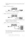
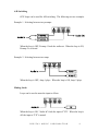
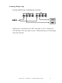
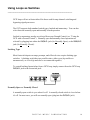
GCX Guitar Audio Switcher OWNER’S MANUAL Please visit our web site at: www.voodoolab.com Copyright 1998 by Digital Music Corporation. This publication is protected by copyright and all rights are reserved. No part of it may be reproduced or transmitted by any means or in any form without the express prior consent in writing from Digital Music Corporation. Ground Control, System Mix, GCX, and Ground Link are trademarks of Digital Music Corp. Table of Contents ________________________________________________________ Introduction . . . . . . . . . . . . . . . . . . . 3 Overview Front Panel Rear Panel Unpacking Buffered and Passive Feed Thru's . . . . . . . . 5 Why Use the Buffer? Connection Options Audio Loops . . . . . . . . . . . . . . . . . . . 7 Effects Loops A/B Switching Muting Sends Combining Multiple Amps Using Loops as Switches . . . . . . . . . . . . 10 Latching Type Normally Open vs. Normally Closed Momentary Type Using the GCX with a Ground Control . . . . . . 12 Connection Setup Mode Controlling GCX Loops Using the GCX without a Ground Control . . . . . 14 Warranty . . . . . . . . . . . . . . . . . . . . 15 DIGITAL MUSIC CORPORATION Introduction ________________________________________________________ Overview The GCX Guitar Audio Switcher greatly expands the capabilities of your Ground Control foot controller. With the GCX, you can select pedal effects, signal processors, multiple amps or preamps, amp channels and more. The GCX has two 1/4 inch feed thru's from front to back. The feed thru labeled "GUITAR IN" is buffered to maximize guitar pickup tone quality, minimize noise, and allow signal splitting to drive multiple devices. The one labeled "FEED THRU" is passive and can also be used from back to front as an amp out. The GCX has eight audio loops, each with separate IN, OUT, SEND and RETURN jacks. They can switch effects in and out, A/B select or mute sends for parallel effects systems, all at either instrument or line level. In addition, loops can be used as latched or momentary switches. Your GCX will phantom power both the Ground Control and Ground Link foot controllers using a standard 5-pin MIDI cable. Front Panel • • • • • Power switch - turns power on to both the GCX and the Ground Control. GUITAR IN - buffered feed thru to the GUITAR OUT on the rear panel. Also normals to the FEED THRU on the rear panel for splitting. FEED THRU - passive feed thru connects to FEED THRU on the rear panel. ACTIVE LED - indicates proper connection to the Ground Control. Also flashes to show MIDI data activity. LOOP/SWITCH STATUS LEDs - show current state of each loop. DIGITAL MUSIC CORPORATION 3 Rear Panel • • • • • • POWER - connect to the supplied external AC adapter. PEDAL IN* - receives MIDI data from the Ground Control and sends power to the Ground Control. MIDI OUT - echoes MIDI data from the PEDAL IN. GUITAR OUT - buffered output from front panel GUITAR IN. FEED THRU - passive connection to the front panel FEED THRU. Also duplicates the GUITAR OUT for splitting when the front panel FEED THRU is not being used. IN/SEND/RETURN/OUT - audio connections for each of the eight loops. * Warning: The Pedal In jack is not a standard MIDI In. To avoid damage, please refer to the section "Using GCX without a Ground Control" before connecting the Pedal In jack to anything other than a Ground Control. Unpacking Your factory carton should contain: 1. 2. 3. 4. This manual The GCX Power adapter Warranty card Please fill out the enclosed warranty card and return it to Digital Music Corp. By registering, you enable us to send you important information about related products, updates and accessories. DIGITAL MUSIC CORPORATION 4 Buffered and Passive Feed Thru's ________________________________________________________ There are two front panel feed thru's which provide convenient connection to your switching system. The feed thru labeled "GUITAR IN" is buffered and the the feed thru labeled "FEED THRU" is passive. The passive feed thru is simply hard-wired from the front jack to the rear. The most common use for the passive feed thru is for an "amp out" connection (passing from the back to the front). You can also use it as an instrument input if you do not wish to use the buffer. Using at least one feed thru ties audio ground to the GCX chassis. This allows the GCX chassis to act as a noise shield for the audio loops and circuitry. Why Use the buffer? Guitar pickup tone is greatly affected by the input characteristics of the device it's plugged into. Unlike typical buffers which utilize bipolar transistor components resulting in unnatural sound, our buffer inputs are carefully matched in both impedance and capacitance to those of tube amplifier inputs. Further, using the latest ultra low noise FET technology provides tube amp characteristics with the lowest possible noise level. The result is an exceptionally transparent buffer which optimizes guitar pickup tone quality. Using the GUITAR IN passes your guitar signal through the in-line buffer which converts from high to low impedance. This improves signal quality, lowers noise, and allows splitting with simple Y-cables to drive multiple devices. Connection Options The rear panel feed thru jacks are both normalled to the buffer. This means that if you use only the GUITAR IN, your buffered signal will appear at both the GUITAR OUT and FEED THRU jacks. This split can be useful for driving a tuner or multiple amps and preamps. DIGITAL MUSIC CORPORATION 5 The following diagrams show some common examples of buffered feed thru connections. Example 1. Using with one instrument: The guitar signal passes from GUITAR IN to GUITAR OUT. Example 2. Splitting from one instrument to two devices: Since the two feed thru's are normalled together, the guitar signal passes from GUITAR IN to both GUITAR OUT and FEED THRU. Example 3. Splitting to more than two devices using Y-cables: Because GCX feed thru's have low impedance outputs, you can drive multiple devices from each output. In this example, the guitar signal passes to all four devices using two Y-cables. DIGITAL MUSIC CORPORATION 6 Audio Loops _______________________________________________________ Important: GCX audio loops are for instrument and line level signals only. Using them to switch amplifier or speaker outputs will severely damage your GCX. The most important characteristic of an audio switcher is sonic transparency. Some manufacturers implement loops using either optoFETs (optical transistors) or LDRs (light dependent resistors), or a combination of the two. Both optoFETs and LDRs cause sound coloration and measurable distortion. Some even claim their switching to be passive while using optoFETs (transistors are not passive). LDRs, while technically passive, are not linear and therefore degrade tone quality. The only completely transparent way to switch both instrument and line level signals with no audible distortion is with relays. The GCX uses the finest gold contact relays sealed in nitrogen. We also include a snubber circuit to improve operation by filtering audio frequencies from the relay coil. Great care has been taken to reduce the possibility of ground loops and hum. GCX audio loop grounds are isolated, the return ground is lifted, and the circuit board includes a noise reducing ground plane. Effects Loops The basic function of a GCX loop is to switch effects in and out of the signal path. In this example, when the loop is ON, the pedal is active. When the loop is OFF, the pedal is bypassed. DIGITAL MUSIC CORPORATION 7 A/B Switching GCX loops can be used for A/B switching. The following are two examples. Example 1. Selecting between two preamps: When the loop is OFF, Preamp-1 feeds the audio out. When the loop is ON, Preamp-2 is selected. Example 2. Selecting between two amps: When the loop is OFF, Amp-1 plays. When the loop is ON, Amp-2 plays. Muting Sends Loops can be used to mute the input to effects. When the loop is ON, "Audio In" feeds the input of "FX". When the loop is off, the input to "FX" is muted. DIGITAL MUSIC CORPORATION 8 Combining Multiple Amps By using multiple loops, combining amps is possible. When loop #1 is ON and loop #2 is OFF, only Amp-1 is active. With loop #1 OFF and loop #2 ON, only Amp-2 is active. When both loops are ON, both amps play at the same time. DIGITAL MUSIC CORPORATION 9 Using Loops as Switches ________________________________________________________ GCX loops will act as footswitches like those used for amp channel switching and bypassing signal processors. The GCX supports both standard switch types, latched and momentary. You can also select between normally open and normally closed operation. Latched or momentary modes are selected from your Ground Control (see "Using the GCX with a Ground Control"). Normally open and normally closed operation are selected by plugging into either the OUT/N.O. jack (for Normally Open), or the SEND/N.C. jack (for Normally Closed). Latching Type Most footswitch inputs on amps, preamps, and effects devices require latching type switches. A latching switch has two possible states, either open (tip and sleeve unconnected), or closed (tip and sleeve are connected together). To control latching footswitches from a GCX loop, simply connect from the GCX loop OUT/N.O. jack to the footswitch jack: Normally Open vs. Normally Closed A normally open switch is open when it's off. A normally closed switch is closed when it's off. In most cases, you will use normally open (plug into the OUT/N.O. jack). DIGITAL MUSIC CORPORATION 10 However, if the GCX status LED is ON when you want it OFF, you can reverse polarity by selecting normally closed. For example, let's say you're controlling reverb on your amp from its footswitch input, but the GCX status LED is ON when the reverb is OFF. You can fix this by changing from normally open to normally closed (plug into the SEND/N.C. jack). The LED will now show the correct state of the reverb. Momentary Type Some devices require momentary type switches. A momentary switch changes state (from ON to OFF or from OFF to ON) by closing for a short time and then opening again. These are most often used for bypass switches on digital effects. To use a GCX loop as a momentary switch, connect the GCX loop OUT/N.O. jack to the footswitch input jack. You must also configure the loop as a momentary switch in the Ground Control setup. DIGITAL MUSIC CORPORATION 11 Using the GCX with a Ground Control ________________________________________________________ Your GCX is part of the Ground Control System, and is easiest to control with the Ground Control Programmable MIDI Foot Controller. From the Ground Control, you can specify whether each loop should act as an audio loop, latched switch, or momentary switch. You can then control loops individually, as well as save loop settings with each of your 100 presets for instant recall. If your Ground Control has the optional expanded memory, you can control up to four GCX Guitar Audio Switchers to provide 32 audio loops and switches. Connection Connect a standard 5-pin MIDI cable from the MIDI OUT of the Ground Control to the PEDAL IN of the GCX. Because the Ground Control will both send MIDI data to and receive power from the GCX, you must use a MIDI cable with all five pins wired (most are). Also, since the Ground Control's power is now supplied by the GCX, you no longer need to use the power adapter which comes with the Ground Control. If you have more than one GCX, connect the MIDI OUT of your first GCX to the PEDAL IN of the second GCX. Continue chaining additional GCXs in this manner. Now connect from the MIDI OUT of the GCX to the MIDI In of your first device. If you have additional devices, connect the MIDI Thru of your first device to the MIDI In of your next device. Continue to chain your devices, MIDI Thru to MIDI In until all your devices are connected. If you are chaining more than 3 additional MIDI devices, using a MIDI Thru box like the Digital Music MX-28S will eliminate data problems caused by generation loss. Setup Mode In Setup Mode, you will first tell the Ground Control that it is connected to a GCX, and then specify how each GCX loop should function. Here's how: DIGITAL MUSIC CORPORATION 12 1. Enter Setup Mode by pressing both Ground Control [SETUP MODE] buttons at the same time. 2. Press [EXPANDERS]. 3. Press [+/YES] so the display reads "GCX-1 ON". 4. Press [CURSOR >] to access the first loop. To use this loop as an audio loop or a latched switch, press [-/NO] so the display reads "GCX 1=NORMAL". To use this loop as a momentary switch, press [+/YES] so the display reads "GCX 1=MOM SW". 5. Repeat step 4 for each of the eight loops. 6. If you have additional GCX modules, press [SELECT ∨] to select GCX-2 and repeat the above. 7. Exit Setup Mode by pressing either [SETUP MODE] button. When the display reads "EXIT Y/N", press [+/YES]. You can now check if you have correctly configured the Ground Control. First turn off both Ground Control and GCX with the GCX power switch. Then turn power back on. After the Ground Control finishes its startup message the Active LED on the GCX will blink and then stay on. This indicates that the Ground Control and GCX are successfully communicating. Controlling GCX Loops Now that you have setup your Ground Control to access the GCX, you can easily control each of the eight loops. 1. Press [SELECT∨] until the Ground Control display reads "GCX-1". 2. Pressing [1] through [8] will control GCX loops. The Status LED's on the GCX front panel, and the LED next to each button on the Ground Control will show the current status of each loop. Creating and Recalling Presets For detailed information on programming, saving, and recalling Ground Control presets, please refer to the Ground Control User's Guide. DIGITAL MUSIC CORPORATION 13 Using the GCX without a Ground Control _________________________________________________________ Warning: The PEDAL IN jack on the GCX is not a standard MIDI In. It utilizes the two normally unused pins to provide 9 volts A.C. power for the Ground Control. Before connecting to a device other than the Ground Control, you must either use a cable without pins 1 and 3 wired, or verify that the MIDI Out of that device conforms to the MIDI specification which states that pins 1 and 3 are unconnected. Failure to do so can result in severe damage to your equipment. If you have any questions about this, please contact Digital Music Corporation's customer service department. It is possible to control the GCX from other devices like MIDI sequencers, some MIDI footpedals, or any device capable of transmitting MIDI Control Change messages. The GCX responds to MIDI Control Change messages sent on channel 16 only. A data value of 0 turns the loop off, a data value of 127 turns the loop on. Controller numbers are as follows: Audio Loop or Latched Switch Loop #1 = controller #80 Loop #2 = controller #81 Loop #3 = controller #82 Loop #4 = controller #83 Loop #5 = controller #84 Loop #6 = controller #85 Loop #7 = controller #86 Loop #8 = controller #87 Momentary Switch Loop #1 = controller #104 Loop #2 = controller #105 Loop #3 = controller #106 Loop #4 = controller #107 Loop #5 = controller #108 Loop #6 = controller #109 Loop #7 = controller #110 Loop #8 = controller #111 DIGITAL MUSIC CORPORATION 14 Warranty NORTH AMERICA ONLY Voodoo Lab warrants this product against any defects that are due to faulty material or workmanship for a period of five years from the date of original retail purchase. This warranty does not include damage to the product resulting from accident or misuse. This warranty is given to the original purchaser only and it is not assignable to any other person. If the product should become defective within the warranty period, Digital Music will repair it or replace it free of charge, provided it is returned freight prepaid to Digital Music with a valid RMA (return material authorization) number. This warranty shall not apply to any goods that have been repaired or altered by anyone other than the manufacturer. There are no warranties which extend beyond the terms described herein. Should you experience any difficulty with this Digital Music product, contact us as described below. If it is determined that the product must be returned to the factory for repair, you will be issued an RMA and given shipping and packaging instructions. OUTSIDE NORTH AMERICA Regions outside North American please contact your country’s distributor for warranty information. You can reach us by any of the following: Tel: Fax: Email: Website: Mail: 707 545 0600 707 545 9777 [email protected] www.voodoolab.com 3165 Coffey Lane, Santa Rosa, CA 95403 DIGITAL MUSIC CORPORATION 15