1
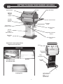
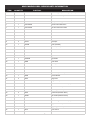
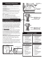
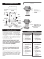
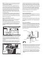
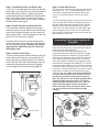
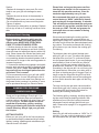
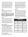
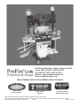
ProFire Grills Perfection by Design Owner’s Manual Assembly and Maintenance Instructions THIS GAS APPLIANCE IS DESIGNED FOR OUTDOOR USE ONLY. www.newphoenixgrills.com FOR YOUR SAFETY If you smell gas: 1. Shut off gas to appliance. 2. Extinguish any open flame. 3. Open Lid. 4. If odor continues, immediately call your gas supplier or your fire department. MODEL: SDBOPN, SDBOPP FOR YOUR SAFETY 1. Do not store or use gasoline or other flammable vapors and liquids in the vicinity of this or any other appliance. 2. An LP cylinder not connected for use shall not be stored in the vicinity of this or any other appliance. MODEL: SDSSOPN, SDSSOPP FOR YOUR SAFETY MODEL: SDBOCN, SDBOCP Follow all leak-test procedures carefully in this manual before using. Do this even if the grill was dealer assembled. Do not try to light this appliance without reading the “Lighting” instructions in this manual. MODEL: SDSSOCN, SDSSOCP YOU MUST READ THIS OWNERS THESE INSTRUCTIONS SHOULD BE LEFT MANUAL BEFORE OPERATING WITH THE CUSTOMER. KEEP THESES IN- YOUR GAS GRILL. STRUCTIONS FOR FUTURE REFERENCE. Note To Customer: We recommend after each use, you turn the control knobs to HIGH (with the lid closed) and run the grill for approximately 10 minutes. This will allow the accumulated fats and greases to cook off, and avoid a possible flare up on the next use. HINT: The fats and greases are cooked off when no more smoke is flowing from the grill vents. Owner’s READ this book first! SAVE this manual for future reference! Your new gas grill is a safe, convenient appliance when assembled and used properly. However, as with all gas-fired products, certain safeguards must be observed. Failure to follow these safeguards may result in hazardous fire or an explosion causing serious bodily injury or property damage. If you have any questions concerning the assembly or operation of this appliance after reading these instructions thoroughly, consult your dealer, gas appliance serviceman, or your propane gas company. The SAFETY symbol identifies the most important safety messages in this manual. When you see the SAFETY symbol, Be Alert to the possibility of personal injury and carefully read the messages that follow. Installer: This instructions MUST be left with the consumer. Consumer: Retain these instructions for future use. SAFETY For Your Safety Never check for gas leaks with a lighted match or open flame. -This grill is for outdoor use only. -Never leave a lit grill unattended. -Do not let children operate or play near your grill. -This grill is for use with propane gas only. -Always leave filled cylinders outdoors. Plan The Location Carefully This grill is for outdoor use only. The grill is not to be used in a building, garage or any other enclosed area. Installation of this appliance must be in accordance with all applicable local codes and gas utility requirements. In the absence of local codes, installation must be in accordance with current National Fuel Gas Code, Z223,I/NFPA54 (Latest Edition) or CAN/CGA-B149.1, Natural Gas Installation Code or Can/CGA-B149.2 Propane Installation Code. This appliance is for outdoor installation only in a well ventilated space. This grill is not intended to be installed in or on any recreational vehicle and/or boats. 2 SAFETY IMPORTANT! Check for compliance to these safety rules before each use! -Maintain a minimum clearance of 24 inches (61 cm) from sides and back of the grill to any combustible construction. -Do not use this appliance under overhead combustible surfaces. -Always keep the area around the grill clear from any combustible materials, gasoline, and other flammable gas and liquids. -Do not block air to the appliance. -Do not block ventilation openings. ment of Transportation (DOT), or the National Standard of Canada CAN/CSA-B339 Cylinder, Spheres and Tubes For Transportation of Dangerous Goods, and Commission as Applicable. Use of LP Cylinder Refer to the assembly instructions section and the label on the LP cylinder for guidance on proper installation and disconnection of the LP cylinder. SAFETY Use of Cylinder Dust Cap The cylinder dust cap provided with your tank must be used whenever the cylinder tank is not connected to the grill gas system. Install the dust cap onto the tank valve. Always use the tank dust cap and be sure the tank valve is closed when storing or transporting the tank. NOTE: -The tank valve must be closed even when using the dust cap. -Always transport, store and use the tank in an upright position. -DO NOT take or store the tank in a building, garage or enclosed area. -Always keep the tank valve closed when the grill is not in use. -When removing the dust cap, do so slowly and only after checking to ensure that the tank valve is still closed. -Read and follow all safety rules in your instruction books and on cylinder tank. LP Gas Cylinder The LP Gas Cylinder which you purchase separately for use with this grill must meet the following requirements and be equipped with a listed Overfilling Protection Device. All LP gas cylinders used with this appliance must be approximately 12" (30.5 cm) in diameter and approximately 18" (45.7 cm) in height. The maximum fuel capacity shall be 20 lbs. (9.1 kg) of Propane (43.7 lbs. normal water capacity). The propane tank must be provided with a shut-off valve terminating in a propane gas tank valve outlet and be provided with an overfilling protection device. Please Note: Your Propane Tank accepts a Type I, also known a “Quick Connect Valve” SAFETY OPD—Overfilling Protection Device As stated, the cylinder you purchase must be equipped with an overfilling protection device. This type of cylinder can be identified by its triangular shaped tank valve and handle (see page 9 for diagram of tank valve and handle). Be Certain if you exchange your cylinder, that the cylinder you receive in exchange has this new OPD safety device. SAFETY Filling the LP Cylinder Have the tank filled by a reputable propane gas dealer. Thee air must be purged from the tank by your propane gas dealer before the first filling. Have your propane gas dealer check the relief valve after filling to ensure that it remains free to function, and check for leaks. The cylinder must be arranged for vapor withdrawal and remain in the upright position. The cylinders must include a collar to protect the cylinder valve. All LP gas cylinders used with this appliance must be marked in accordance with the specifications for LP gas cylinders of the US Depart- SAFETY Storage DO NOT store the LP cylinder in direct sunlight. When the grill is to be stored indoors, the propane tank MUST b disconnected. The 3 Well ventilated space, NOT in a building, garage, or any other enclosed area. It must be out of reach of children. A dust cap MUST be used whenever the tank is disconnected from the grill. When grill is not in use, close propane tank cylinder valve. When the propane tank is connected, the grill must be stored outdoors in a well ventilated space, not in a building, garage or any other enclosed area. Always close the propane tank before disconnecting it from the grill or when the grill is not in use. If the grill is going to be stored for winter or for an extended period of time, we suggest you follow these steps: Phoenix Grill dealer or local gas utility in accordance with all applicable codes. CAUTION: Any additions, changes, or conversions required in order for the appliance to satisfactorily meet the application needs must be made by a Scottsdale dealer or local gas utility using factory specified and approved parts. Always remember to shut gas off at gas connection when grill is not in use. SAFETY Leak Test Check for leaks before lighting the grill for the first time, after storing the grill between seasons and after refilling the propane cylinder. Take your grill outdoors into a well ventilated area. Do not use or permit sources of ignition in the area during this test, this includes smoking. Use only a soap and water solution to test for leaks. -The burner should be cleaned and coated lightly with cooking oil to prevent from rusting. -The venture openings should be covered with aluminum foil to prevent small insects from entering the opening during storage and must be removed before using. -The grill should be covered if it is left outdoors. Grill covers are available as an accessory. -Follow the cleaning procedures. Leak Test Check List -Tank valve (all over) including area that screws into the tank and the welds. -Regulator fitting -Hose connections -Valves Hose and Regulator The pressure regulator and hose assembly supplied with the appliance must be used. This pressure regulator is preset for an outlet pressure of 11 inches (27.9 cm) water column. Therefore, this pressure regulator MUST be used with your Scottsdale Grill. Before each use of the grill inspect the hose for wear, cracking and examine for any cuts. If any these conditions exist, do not use, purchase a new hose and regulator. If a replacement is needed, refer to the parts list for the part number and contact the dealer where your grill was purchased. Refer to “Connecting the Cylinder to the Grill” for details of hooking up your regulator to the LP gas cylinder. Make sure a leak test is performed every time you have your LP gas cylinder refilled, and visibly inspect for excessive wear and damage on a regular basis. Always follow the directions for the “Leak Test”. Natural Gas Your grill may be converted to natural gas by replacing the LP Valve with the appropriate Natural Gas Valve. (Part #HHVLV32-SD). A conversion is only be made by an authorized Mandatory Leak Test 1. Have propane tank filled with propane gas only by a reputable propane gas dealer. 2. Attach regulator fitting to tank valve. 3. Tighten regulator fitting securely. 4. Turn the control knobs to the right, clockwise. This is the “OFF” position. 5. Make a solution of half liquid detergent and half water. 6. Turn gas supply “ON” at the tank valve (counter clockwise). 7. Brush soapy mixture on all connections listed in the Leak Test Check List. 8. Observe each place for bubbles caused by leaks. 9. Tighten any leaking connections, if possible. If leak cannot be stopped, DO NOT USE THE GRILL. Order new parts from an authorized Scottsdale dealer. Do not use the grill until after the new parts are installed. After installing new parts, perform complete leak test. 10. Turn gas supply “OFF” at the tank valve. 4 Phoenix Grill WARRANTY LIMITED LIFETIME WARRANTY ON THE FOLLOWING: • Cast Aluminum End Caps • Stainless Steel Top Insert • Stainless Steel Bottom Insert • Control Panel • Stainless Steel or Aluminum Column • Deck/Patio Base • Portable Base • Stainless Steel Cooking Grid • Stainless Steel Fasteners 10-YEAR WARRANTY ON THE FOLLOWING: • Stainless Steel Burner • Cast Aluminum Drip Pan • Stainless Steel Shelf 5-YEAR WARRANTY ON THE FOLLOWING: Black Aluminized Steel Top Insert • Black Aluminized Steel Bottom Insert 1-YEAR WARRANTY ON THE FOLLOWING: All other Components including; Igniter System • Gas Valves • Knobs • Wheels WHAT IS NOT COVERED: Transportation and shipping cost • Labor for replacement or repairs • Damage from accident, misuse, alteration, abuse, improper installation or storage • Removal and reinstallation costs • Finishes on surface that are damaged by improper installation, improper storage, accident, misuse, abuse or alteration • Inoperable due to improper installation or storage • The costs of a service call to diagnose a problem • All warranties are non-transferable and apply only to the original purchaser • Warranties are null and void if grills are put into commercial or community use. This warranty does not imply or assume any responsibility for consequential damages that might result from use, misuse, or improper installation of this cooking appliance. This warranty does not cover claims, which do not involve defective workmanship or materials, bill of sale, cancelled check, or payment record should be kept to verify purchase date and establish warranty period. MODEL IDENTFICATION Your Phoenix Grill is identified by a model number and a serial number located on the left side of the control panel. Always use both the model and serial numbers when contacting Modern Home Products about your grill. For future reference, take the time now to record the model and serial numbers below: MODEL NUMBER: ______________SERIAL NUMBER: ________________DATE PURCHASED:__________________ How to contact us: phone: 1-888-781-4657, fax: 1-800-781-3965, E-mail: [email protected] or write: Customer Service, ProFire Grills 5565 North 124th Street, Butler, WI 53007. 5 GETTING TO KNOW YOUR PHOENIX GAS GRILL Heat Indicator Right Side Shelf Grill Lid Sta-Kool Stainless Steel Handle Left Side of Burner Control Utensil Hooks Electronic Igniter Right Side of Burner Control Drip Pan Drain Valve Column Stainless or Black Aluminum Grease Collector Bucket Deck/Patio Base Gas Valve Access Panel 2010 Models Come Standard With Right and Left Side Shelf. REAR VIEW Vents INSIDE VIEW Vent Slide Tank Locking Bar Drip Pan Dual Burner and Gas Collector Box Portable Base Cooking Grid 12 Ft. Hose with Quick Disconnect Included with Natural Gas 6 MHP PHOENIX GRILL SERIES PARTS INFORMATION ITEM QUANTITY PART NO. DESCRIPTION 1 1 GGEIB Electronic Ignitor (AAA Battery Required) 2 1 GGIB Ignitor Box Assembly 3 2 GGK10SD Valve Knob 4 1 GGTG4 Temperature Gauge 5 1 HHVLV28SD LP Gas Valve #60 Orifice 6 1 HHVLV32SD Nat. Gas Valve #53 Orifice 7 1 OBSSD34 Burner with Venuris 8 1 GGOAPB Fixed Base 9 2 GGAWP Axle Wheel Pins 10 1 GGAXL Axle 11 2 GGHC1 Hub Caps 12 1 GGOCB Base (Portable) 13 2 GGWL1 Wheels (6 Inch) 14 1 OCOL/OCOLB Stainless Column– Black Aluminum Column 15 1 GGGLG Gas Line Grommet For Column 16 1 GGGSKA (A) Gasket 17 1 GGGSKB (B) Gasket 18 1 SDBB Back Brace 19 1 SDCG Cooking Grid 20 1 SDCP Control Panel 21 1 SDCPLBL Control Panel Label 22 1 SDDV Drain Valve (3/4" MPT) 23 1 SDGB Grease Bucket 24 2 SDHP Hinge Pins 25 2 LPP1 Hinge Pin Clips 26 1 SDLI Stainless Lower Sheet Metal (Pit) 27 1 SDLLEC Lower Left End Cap 28 1 SDLREC Lower Right End Cap 29 2 SDSS Side Shelf (Stainless Steel) 30 1 SDSSH Lid Handle (Stainless Steel) 31 1 SDSSDT Drip Pan 32 1 SDUI Stainless Upper Sheet Metal (Lid) 33 1 SDULEC Upper Left End Cap 34 1 SDUREC Upper Right End Cap 35 1 SDVC Vent Control 36 2 V34 Venturi Tubes 7 Assembly Instructions Rec. Washers Only For Aluminum Column Tools Required For Assembly: 7/16" Wrench, 7/16" Socket Wrench With Extension, 3/8" Wrench. CAUTION: Edges of grill may be sharp, use care when assembling grill. CAUTION: While handling the grill head be very careful not to damage the Venturi Tubes or the Ceramic Ignitor Insulator which protrudes from below the grill. 2-Piece Gasket For Stainless Column Only Fig. 2 Attach in this order– Bolt, Rec. Washer, Washer, Kep Nut NOTE: Your Phoenix Grill consists of (3) cartons: Box 1- Grill Head Box 2- Black or Stainless Steel Column Box 3- Cast Aluminum Cart or Flat Base The column and base should be assembled first, then the grill head to the completed base assembly. Models: SDBOPN Nat. Gas SDBOPP LP Gas Assemble As Follows: Step 1: Follow this step if you have selected the Black Aluminum Column Mount. Black Column with Fixed Base Go To Step 1A If You Have A Stainless Steel Column A. In box #2, find and attach the LP Tank Locking Bar across the back of the column. This spreads and holds the correct spacing at the back of the column regardless of the type of gas that will be used. Use the (2) 3/4" Hex Bolts, Nylon Lock Bar Spacers and Kep Nuts to fasten the lock bar in place. (Fig. 1) B. Align the Holes! Attach the column to the base using six 3/4 inch bolts, four large rectangular washers, and on the underside, six round washers and six Kep nuts. This assembly work is most easily done with the column lying on its front or back to provide access to the washers and nuts beneath the base. (Fig. 2) IMPORTANT! The large rectangular washers are used at the column left and right sides on top of the bottom lip and under the head of the bolts. The six round washers are used under the casting. Tighten all securely and stand unit upright. Models: SDBOCN Nat. Gas SDBOCP LP Gas Black Column with Portable Cart Base HARDWARE BY MODEL C. On portable bases, attach the wheels by slipping the axle through the base, slide the wheels on and install the axle clips. Finish by snapping the hubcaps on. Flat base permanent models must be Lag Bolted to the deck or concrete for stability. (Fig. 3) Ctn. No. FIXED BASE (Propane) Ctn. No. FIXED BASE (Nat. Gas) 2 3 2 2 2 2 2 2 2 2 3 2 2 2 2 2 2 2 1 1 1 12 6 2 12 4 1 Stainless Steel Front Panel Cast Aluminum Base Aluminum Column 1/4-20 Kep Nuts 1/4" Washer (7/8" OD) Nylon Lock Bar Spacers 1/4-20 x 3/4 Inch Hex Bolts Rectangular Washers Tank Lock Bar Ctn. No. Nylon Spacer 2 3 2 2 2 3 3 3 2 2 2 2 Axle, Wheel, Clip Pin and Hub Cap Tank Locking Bar Kep Nut Fig. 1 Hex Bolt Fig. 3 8 1 1 1 12 6 2 1 2 2 12 4 1 CART (Propane) Stainless Steel Front Panel Cast Aluminum Base Aluminum Column 1/4-20 Kep Nuts 1/4" Washer (7/8" OD) 6 Inch Wheels Axle Axle Clips Nylon Lock Bar Spacers 1/4-20 x 3/4 Inch Hex Bolts Rectangular Washers Tank Lock Bar 1 1 1 12 6 2 12 4 1 Stainless Steel Front Panel Cast Aluminum Base Aluminum Column 1/4-20 Kep Nuts 1/4" Washer (7/8" OD) Nylon Lock Bar Spacers 1/4-20 x 3/4 Inch Hex Bolts Rectangular Washers Tank Lock Bar Ctn. No. 2 3 2 2 2 3 3 3 2 2 2 2 3 1 1 1 12 6 2 1 2 2 12 4 1 2 CART (Nat. Gas) Stainless Steel Front Panel Cast Aluminum Base Aluminum Column 1/4-20 Kep Nuts 1/4" Washer (7/8" OD) 6 Inch Wheels Axle Axle Clips Nylon Lock Bar Spacers 1/4-20 x 3/4 Inch Hex Bolts Rectangular Washers Tank Lock Bar Hub Caps PHOENIX Assembly Instructions CONNECTING GRILL TO COLUMN 4 BOLTS 3/4" 4 KEP NUTS Models: SDSSOPN Nat. Gas SDSSOPP LP Gas Back of Grill Stainless Steel Column with Fixed Base BOLT GRILL INSTALL BOTH ENDS COLUMN NUT HEAT SHIELD CONNECTING COLUMN TO BASE TANK LOCKING BAR IN THIS ORDER RECT WASHERS Note: Rect. Washers Only For Aluminum Column BASE 6 BOLTS 3/4" 4 RECTANGULAR WASHERS 6 1/4 FLAT WASHERS 6 KEP NUTS NYLON SPACER ACCESS FOR GAS LIN ABOVE DECK OR PATIO Models: SDSSOCN Nat. Gas SDSSOCP LP Gas THIS BASE IS A FIXED (NO WHEELS) AND MUST BELAGGED TO A DECK OR CONCRETE FOR STABILITY. USE THESE 2 HOLES. Stainless Steel Column with Portable Cart Base Step 1A. Follow This Step If You Have Selected A Stainless Steel Column. HARDWARE BY MODEL A. In box #2, find and attach the LP Tank Locking Bar across the back of the column. This spreads and holds the correct spacing at the back of the column regardless of the type of gas that will be used. (Fig. 1 Page 8) B. NOTE: Make sure the protective white film is peeled away from any area that may not be accessible after assembly. Before bolting the stainless steel column to the cast aluminum base, a 2-piece adhesive gasket must be installed to make a barrier between the two metals. Remove the backing strips to expose the adhesive and stick the gasket to the bottom lip of the stainless steel column. Align the holes. (Fig. 2 Page 8) Attach the column to the base using six 3/4" bolts with (6) round washers, and on the underside, six round 7/8" dia. washers and six KEP nuts. This assembly is most easily done with the column lying on its front or back to provide access to the washers and nuts beneath the base. Tighten securely and stand unit upright. Ctn. No. FIXED BASE (Propane) Ctn. No. FIXED (Nat. Gas) 2 3 2 2 2 2 2 2 2 2 3 2 2 2 2 2 2 2 1 1 1 12 12 2 12 1 1 Stainless Steel Front Panel Cast Aluminum Base Stainless Column 1/4-20 Kep Nuts 1/4" Washer (7/8" OD) Nylon Lock Bar Spacers 1/4-20 x 3/4 Inch Hex Bolts Tank Lock Bar 2-piece Gasket Ctn. No. 2 3 2 2 2 3 3 3 2 2 2 3 2 C. On portable bases, attach the wheels by slipping the axle through the base, slide the wheels on and install the axle clips. Finish by snapping the hubcaps on before standing upright. Flat base permanent models must be Lag Bolted to the deck or concrete for stability. (Fig. 3 Page 8) 9 1 1 1 12 12 2 1 2 2 12 1 2 1 CART (Propane) Stainless Steel Front Panel Cast Aluminum Base Stainless Column 1/4-20 Kep Nuts 1/4" Washer (7/8" OD) 6 Inch Wheels Axle Axle Clips Nylon Lock Bar Spacers 1/4-20 x 3/4 Inch Hex Bolts Tank Lock Bar Hub Caps 2-piece Gasket 1 1 1 12 12 2 12 1 1 Stainless Steel Front Panel Cast Aluminum Base Stainless Column 1/4-20 Kep Nuts 1/4" Washer (7/8" OD) Nylon Lock Bar Spacers 1/4-20 x 3/4 Inch Hex Bolts Tank Lock Bar 2-piece Gasket Ctn. No. 2 3 2 2 2 3 3 3 2 2 2 3 2 3 1 1 1 12 12 2 1 2 2 12 1 2 1 1 CART (Nat. Gas) Stainless Steel Front Panel Cast Aluminum Base Stainless Column 1/4-20 Kep Nuts 1/4" Washer (7/8" OD) 6 Inch Wheels Axle Axle Clips Nylon Lock Bar Spacers 1/4-20 x 3/4 Inch Hex Bolts Tank Lock Bar Hub Caps 2-piece Gasket 12 Ft. Nat. Gas Hose with Quick Disconnect Step 2. At this point you have assembled the Pedestal/ Column and Base Assembly, and will now proceed to the grill head itself, (carton 1.) With the grill head still in its box, cut down all (4) corners of the box to expose the grill head. Remove and set the grill Lid aside. Remove the Control Panel inter pack, side shelf, grease bucket, and cooking grid which are packed inside the grill head. Last, remove the “V” shaped stainless drip pan from the bottom of the grill head. Remove the grill head being very careful not to damage the Venturi Tubes or Ignitor Insulator protruding from the bottom. On a protective sheet of cardboard, stand the grill head on its side and remove the two (2) wing nuts holding the burner in place. Remove the Burner/Venturi assembly from the unit. It will be reinstalled later and secured with the two (2) wing nuts. Install the (2) decorative acorn nuts which are packed with the control panel knobs, etc. (Do Not Over Tighten). Next, swing the panel up to the front of the pit and align the two sets of holes (Fig. 5). From inside the pit, attach the control panel with the previous removed 3/4" x 1/4" x 20 hex bolts and lock washers. Connect the ignitor wire to the ceramic electrode beneath the grill. Install the battery (+) side down and install the ignitor button by pushing firmly and turning clockwise. Step 3. Fasten Grill Pit To Column NOTE: Before proceeding further remove the protective white film from the outside of the lower pit assembly and the upper portion of the column. Set the grill pit onto the top of the column and align the four (4) pit mounting holes to the matching holes in the column lip. Install (4) 1/4 x 20 x 3/4 inch hex bolts from the top and install and tighten (4) 1/4 inch KEP nuts. (Fig. 4) Align the two holes in the brace to the two holes in the rear of the pit. From inside the pit fasten the brace with the previously removed 3/4" x 1/4" x 20 hex bolts and washers. Bolt In This Order Install the (2) control panel knobs. Sept 5. Install Back Brace Locate the small back brace panel and remove the protective film. Remove the preinstalled 3/4" x 1/4" 20 hex bolts and lock washers. Place back brace at the rear of the unit on top the column. Step 6. Reinstall Burner Reinstall the burner/venture assembly into the grill pit making sure the venture tubes fit over the valve orifices 1/4" to 1/2" as shown below (Fig 6). Gas exits the orifices and enter the venture tubes where it mixes with air coming in from the side of the air shutters. The proper mixture of air and gas produces the desired blue flame at the burner. Back of Grill Bottom BOLT Control Panel KEP Nut Lip Fig. 4 Sept 4. Attach Control Panel Unpack the assembled control panel. Propane models have the Hose/Regulator preassembled at the valve. Remove the (2) 3/4" x 1/4" x 20 hex bolts and lock washers that are preinstalled in the panel. They will be REUSED. Standing in front of the grill, prepare to install the control panel by first hanging the panel onto the (2) thread studs protruding from the top of the column. Fig. 5 Valve Venturi Tube Fig. 6 Air Shutter Warning! Always check the alignment of the orifice and the venture whenever the grill has been moved. Make sure that the orifice fits into the venture tube 1/4" to 1/2" . Failure to make this connection may cause fire and result in serious body injury or damage to your grill. Acorn Nut 3/4 x 1/4 x 20 Bolt Through Bottom Pit Valve Orifice The threaded burner posts go through the matching holes in the pit bottom. Make sure the (2) wing nuts are installed from underneath onto the threaded studs. Fig. 5 10 Step 7. Reinstall Drip Pan and Drain Valve Lower the “V” shaped drip pan into the pit with the drain pipe to the right side, as it will go through the hole at the bottom of the pit. Lightly coat the exposed threads with pipe sealant and thread on the drain valve. Make sure it is in the open position. Hang the grease bucket from the valve. Install the stainless steel cooking grid. Step 9. Install Side Shelves The shelves are mounted on the right side and left side with the (8) 3/4" x 1/4 x 20 bolts and washers. They are found in a bag attached to the side shelves. Remove any remaining white film from the grill and/or mount. You are now ready to light the grill but, first be sure you have read this entire manual, and follow all the warnings and safety instructions included. Prior to lighting the grill, conduct the leak test described on page 3 “Leak Test”. Once these have been read and the grill has been lighted, allow it to burn for 15 minutes with both controls on high and lid closed to remove any oils before starting to cook food. Step 8. Install From Access Panel and Lid First, make sure that the regulator hose is positioned into the slot on the column and that the regulator itself is passed through into the column below the heat shield. It will be connected to the tank which will sit in the column. (Fig 7) Connecting The Propane Cylinder To Your Grill Carefully place lid onto the grill pit and align the holes of the upper and lower hinges. Reinstall the lid pins and securing clips. Remove the remaining protective white film from the Lid and all other body parts. Install the gas cylinder in the back of your grill, with the open side of the tank valve collar pointing towards the square hole in the tank enclosure. Ensure that all hoses, fittings and regulators are properly protected from heat and accidental damage. Hoses can be burned or chaffed if routed improperly. (See Hose and Regulator, page 3). Be sure all burner control valves on the grill are turned off. To connect hose and regulator to cylinder turn coupling nut clockwise as shown in diagram below (Fig. 8). (To remove the quick connect coupling nut, turn counter clockwise.) Your Phoenix Grill comes with a Type I connector, also known as a “Quick Connect Valve” connection. It has a large plastic “coupling nut” that screws onto the propane tank gas outlet. Note: Your Phoenix Grill does not come with a propane tank. Therefore, be sure the tank you purchase has this type of hook-up. Also, the cylinder you use must be equipped with a listed overfilling protection device. This can be identified by the triangular hand wheel. (See diagram below and page 2 of these instructions). Please remember when you Phoenix Grill is not in use, the gas must be turned off at the supply cylinder. Step 9. Install Access Panel The front access panel attaches directly under the control panel and hides the access opening. Lift the access panel up behind the lip of the control panel, then slip the bottom double edge of the access panel (upward pressure may be needed) over the edge of the access opening (Fig. 7). Access Panel Covers Access Opening COUPLING NUT VALVE OUTLET HANDWHEEL CYLINDER VALVE Upward Pressure NIPPLE Fig. 7 DUST CAP & STRAP REGULATOR 11 Fig. 8 First Time After Storage Checklist An obstructed venture tube is not the only cause of “Flashback”, it is the most common cause. There, to avoid this problem, frequent inspection and cleaning of the venture tubes is necessary, even before the first operation of the grill. Failure to do so may result in a fire beneath your grill. See (Care and Maintenance Section” for proper procedure to ensure clean venture tubes. SAFETY Prior To Use Listed below are steps to follow each time you use your grill. If this is the first time, be sure you read and understand all information in this manual. -Your grill parts have been coated with a preservative to prevent rust. Prior to the first use, it is important that the grill be lit and allowed to operate on “HIGH” for at least 15 minutes with the lid closed before any food is placed on the cooking surface. -If the grill has been moved or cleaned, be sure the venturis are properly located. The valve outlets MUST be inside the venturis. Improper positioning could cause property damage or personal injury. (See Picture on Page 5.) -Be sure all gas connections are free from leaks. (See “Leak Testing” procedure). -Be sure any electrical supply cords and/or any fuel supply hoses are kept away from hot surfaces. -Be sure to periodically clean the venturis. (See “Care and Maintenance” for cleaning procedure). -Be sure ventilation openings of the cylinder enclosure are kept clean and clear of debris. -Do not move the grill when lit. SAFETY LIGHTING -Have you completed the “Leak Test” procedure? If not, do so before attempting to light grill. -Be sure you have followed the “Prior to Use” and all safety instructions before lighting grill. -Open grill top before lighting. NEVER light grill with top down. -Make sure that control knobs are on “OFF”. -Turn the gas supply on at the propane cylinder. Ignitor and Match Lighting Procedure Push-button Lighting Procedure: 1. Push in and turn either left or right control knob to “HI”. 2. Immediately push igniter button all the way in until ignition is heard, then release. Check through center peep hole to verify ignition has taken place. Adjust burner knobs to desired heat setting. 3. If ignition does not occur within 5 seconds turn burner control(s) off. Wait 5 minutes and repeat lighting procedure. WARNING NEVER Move Grill After It Is Lit. Natural Gas Precautions If your Phoenix Grill has been converted to natural gas by an authorized Phoenix Grill Distributor then please follow the precautions described hereafter. Match Lighting Procedure: You may also elect to use a match to light your grill. Place a match in the hole left of the drip pan valve, then push in and turn the right control knob to “HI” until you see the gas is lit through the peephole located just above the control knobs. Then follow steps 3 and 4 above. Caution: The outdoor cooking gas appliance and its individual shutoff valve must be disconnected from the gas supply piping system during any pressure testing of that system at test pressures in excess of 1/2 PSI (3.5 KPA). IMPORTANT: If the burner flame goes out when the unit is in use, always turn gas control knobs to “OFF” immediately. Open grill lid and wait 5 minutes before relighting. Always turn off the gas supply at the propane tank valve when the grill is not in use. Beware of Spiders In some areas of the country, spiders and small insects have been known to spin webs or make nests inside of the venture tubes. These webs can lead to gas flow obstruction which could result in a fire in and around the venture tubes. This type of fire is commonly known as a “Flashback”, and can cause serious damage to the grill and create an unsafe operating condition for the user. Although 12 BURNER FLAME APPEARANCE 1. Remove the burner assembly from the grill bottom. See step 25 in the assembly instruction section on how to remove. 2. Bend a stiff wire, (a lightweight coat hanger works well) into a small hook. Run the hook up through each venture tube past bend and into the burner several times. 3. Use a bottle brush with a flexible handle. Run the brush up through each venture tube past bend and into the burner several times. Should “Flashback” occur, immediately turn the control knob to “OFF” and carefully turn the gas supply off at the propane tank. Wait until your grill has cooled, and determine the cause. The “Trouble Shooting Guide” (found in this manual) lists other causes of “Flashback” and can be helpful in determining the cause and solution. Correct problem, and replace any damaged parts before using grill. Burner Flame YELLOW YELLOW BLUE BLUE GOOD FLAME BAD FLAME Visually check the burner flame appearance each time the grill is used. A good burner flame should be blue with some yellow at the tip. If the burner flame is nearly all yellow, check the following: -Are the burner holes clogged? If so, refer to “Care and Maintenance” section for cleaning instructions. -Are the venture tubes blocked? If so, refer to “Care and Maintenance” section for cleaning instructions. -Are venturis properly located on the valve outlets? Refer to “Prior to Use” section. Correct problems if any. If, after checking all of the above, your flame still burns with yellow tips, your burner needs to be adjusted. Located on your venture tube is an air shutter that can be adjusted. It is located on the end of the venture valve where it connects to the control valve. Loosen the screw and adjust the shutters until a correct flame appears. Burner Cleaning Regardless of which venture cleaning procedure you used, we recommend that you complete the following steps to help prolong burner life. -Wire brush entire outer surface of burner to remove loose corrosion. -Clean any clogged holes with a stiff wire (for example, an open paper clip). -Inspect the burner and venturis for any opening caused by corrosion. -If openings due to corrosion are found, order a new burner. -Check the burner for proper location after replacing. -Check to assure the valve outlets are inside of the venturis. -Check to ensure that the Wing Nuts that hold the burner, are tight. Periodically check and tighten as needed. DAMPER OPERATION Adjust the damper to the desired position prior to lighting up the grill because the adjusting screw will become HOT after the grill has been lit. Care and Maintenance Section As with all appliances, proper care and maintenance will keep them in top operating condition and prolong their life. Your new gas grill is no exception. By following these cleaning procedures on a timely basis, your grill will be kept clean and working properly with minimum effort. SAFETY Venturi Cleaning To reduce the chance of “Flashback”, the procedure below should be followed at least once or twice a month, especially in late summer and early fall when spiders are most active, or whenever your grill has not been used for an extended period of time. Following we provide two methods for cleaning the venture tubes. Follow the procedure that is most convenient for you. Annual Cleaning 13 At least once a year you should follow these steps to give the entire appliance a thorough cleaning. This will help maintain your grill in top operating condition. -Remove all components from inside your grill. -Cover the valve orifices with a small piece of aluminum foil. (Note: Remove foil after cleaning). -Brush interior surfaces of the housings with a stiff wire brush. If desired, the interior and exterior may be washed. -Brush the burner and any clogged holes with a stiff wire. For more detailed instructions, see “Burner Cleaning” section. -Clean the venture tubes and inspect parts for corrosion as described in the “Venturi Cleaning” Please Note: as long as the grease can flow into the grease bucket it is not necessary to clean the drip pan after each use. Clean as needed or approximately every 10 uses. Section. -Replace all damaged or worn parts. Do not attempt to use your grill with damaged or worn parts. -Replace all parts as shown in the assembly instructions. -Check for proper burner and venture placement. -Do not operate with any loose or missing bolts. Tighten or replace. -Check hose for deterioration or damage. Replace at first sign of leak or if “cracking” becomes noticeable. We recommend after each use, you turn the control knobs to “HIGH” (with the lid closed) and run the grill for approximately 10 minutes. This will allow the accumulated fats and greases to cook off, and avoid a possible flare up on the next use. HINT: The fats and greases are cooked off when no more smoke is flowing from grill vents. Stainless Steel Cleaning We recommend cleaning the cooking surface (cooking grid) before each use and before you light the grill. Simply run a wire brush front to back and side to side across the diamond shaped cooking surface. This can be performed with cooking grid in place or you can remove the cooking grid for cleaning. Before cleaning, determine which way the “grain” of the metal runs and always clean with the grain. NEVER USE STEEL WOOL PADS TO CLEAN STAINLESS STEEL. 1. Routine cleaning is done with a warm soapy water applied with a sponge or soft cloth. Always rinse with clean hot water and wipe dry with a soft cloth. Glass cleaners like Windex also works well. 2. Stubborn stains can be removed with a mild non-scratching abrasive household powder. Add a small amount of vinegar to the scouring powder to increase its potency. 3. Commercial stainless steel cleaners and polishers also work well, such as MHP’s Stainless Steel Cleaner (Part #SSC). Note: Over time the stainless steel will turn a mild gold patina from the grill’s heat. This is normal. 4. We recommend covering your grill with a MHP felt-backed cover. A cover will prolong the life of the grill and prevent rain water from draining into the grease bucket, causing it to overflow. A cover can be purchased through you Phoenix Dealer. The drip pan drain valve should be kept open while your grill is in use. This allows the grease that drips from your food. To continuously drain into the grease catch bucket. If you are cooking a small quantity of food or food with very little fat, you may not notice any grease collecting in the grease bucket. However, If you notice grease accumulating in the drip pan but it is not running into the grease bucket, then either your drain valve is not open or the drip pan pipe is clogged. Don’t attempt to clear the clog while the grill is hot! Wait until the grill has cooled, remove the cooking grid and run a stick down the drain pipe until the clog is cleared. The only time the drip pan drain valve should be closed during grill use, is when you are steaming or smoking with liquid smoke. See below for steaming and smoking instructions. COOKING TIPS FOR YOUR PHOENIX GAS GRILL Thank you for purchasing a Phoenix grill. Your new Phoenix eliminates flare-ups because the cooking surface is shielded from direct flame contact by a drip pan. For best results we recommend that all preheating, grilling, smoking, baking and steaming be performed with the lid closed! (Warning: Always light your grill with the lid open. The following grilling, steaming, smoking and baking tips are provided as helpful guidelines. With experience you will find the cooking times and temperature control settings that best suit your taste. Please refer to page 15 for suggested cooking times. Grilling Heat your grill with both controls on “HIGH” for 15 minutes. If you are cooking hamburgers or steaks we recommend that you leave the temperature GETTING STARTED Before you use your grill for the first time be sure to read and thoroughly understand all grill safety, lighting, locating, operating and maintenance procedures found in this book. 14 Controls on the high setting. Remember for best results, cook all your foods with lid closed. If you are cooking chicken, turkey, roasts, hot dogs or sausages we recommend that after pre heating your grill on high you then turn both controls on the medium settings (half way between the high and low setting). To Keep food warm, or to further slow the cooking process, you may try running only one side of the grill and warming or cooking on the opposite side. Or you may try cracking the lid (with a wood spacer) to let out heat. Drip pan drain valve and fill the drip pan with water (be sure not to overfill your drip pan). Add several ounces of liquid smoke, experience will dictate how much liquid smoke is required to suit your taste. Heat the grill with both controls on “HIGH” for 20 to 25 minutes. Keep controls on the high settings and cook to desired taste. Add more water and liquid smoke if you are cooking for an extended period of time. Do not attempt to move your grill with water in the drip pan, and wait until your grill has cooled before draining out any remaining water. Baking Pre-heat with both controls on high for 10 minutes. Then set your controls to the following setting that most closely matches the temperature you wan to achieve: Steaming Caution: Before you proceed, make sure that your grill is on a solid surface. Check to see that your drip pan is relatively clean, see “Smoking” instructions for drip pan removal and cleaning. Close the drip pan drain valve and fill the drip pan with water (be sure not to overfill). Heat the grill with both controls on “HIGH” for 20 to 25 minutes. Keep controls on the high setting and cook to desired taste. Steaming is good for such foods as; oysters, clams, lobsters, and shrimp, etc. Do not attempt to move your grill with water in the drip pan, and until your grill has cooled before draining out any remaining water. Low Setting 325 Degrees to 375 Degrees Middle Setting 375 Degrees to 425 Degrees High Setting 425 Degrees to 500 Degrees (Hint: the lid thermometer will help to more accurately set your controls) Smoking Caution: Before you proceed, make sure that your grill is on a solid level surface. Check to see that your drip pan is relatively clean. Smoking or steaming with a dirty drip pan can affect the taste of your food. To clean your drip pan, simply unscrew the drain valve and lift out the drip pan. Never attempt to clean the drip pan while the grill is hot or if the grill is in use. A putty knife or scraper works well for cleaning out the drip pan. Wood Chip Smoking Place the desired amount of wood chips in a wood chip container. You can fabricate your own container(s) by folding heavy gauge aluminum foil into an open square or purchase a MHP stainless steel smoker box (part #SDSSST) from your Phoenix Dealer. Place one or more containers directly on top of the drip pan located under the cooking grid. Do not place the container in the middle of the drip pan. For best results place the container halfway between the center and the edge of the drip pan. Heat the grill on “HIGH” for 30 minutes, or until you detect smoke, before you place your food on the grill. Cook to desired taste. COOKING TIMES A Quick Reference Chicken 3 lb. Whole Chicken Chicken Legs or Thighs Pork Chops 45-60 Minutes 1 Inch Thick Italian Sausage Pork Sausage 90 Minutes 15 Minutes Each Side 40 Minutes Patty 8 Minutes Each Side Pork Ribs 60 Minutes Prime Rib 2 1/2 Hours (Use Meat Thermometer) Vegetables All 30 Minutes Biscuits Canned 7 Minutes Each Side Liquid Smoking Grilling Make sure your drip pan is relatively clean, see above for drip pan removal cleaning. Close the 15 TROUBLE SHOOTING GUIDE If you are having difficulty with your grill, follow this guide to solve some common problems. Problem #1: BURNER(S) WILL NOT LIGHT OR THE GRILL DOES NOT GET HOT ENOUGH. PROBABLE CAUSE SOLUTION A. Propane Cylinder Almost Empty. Have Propane Cylinder Filled. B. Propane Cylinder Valve Not On. Turn Valve On. Turn Counter-Clockwise to Open. C. Kink In The Gas Hose. Reposition The Propane Cylinder To Straighten The Hose. D. Burner Holes Clogged. Clean With Small Wire or Round Toothpick and Sire Brush the Entire Burner. See “Care and Maintenance” Section For Further Instructions. E. Venturi Blocked. Clean Venturis. Refer to “Venturi Cleaning” Section F. Venturis Not Sealed. Refer to “Prior to Use” Section G. Orifices In Valve Outlet Plugged. Clean Orifices (small hole in valve outlet). H. Regulator And/Or Valve Defective. Take Complete Hose, Valve and Regulator Assembly to a Servicing LP Gas Dealer for Inspection. I. Ignitor Not Working. Check For Proper Electrode Gap. Make Sure All Wires Are Connected and None Broken. Check Ceramic for Cracks. Problem #2: FLASHBACK (fire in venture or control panel area). IF FLASHBACK SHOULD OCCUR, SHUT CONTROLS OFFTHEN TURN VALVE OFF AT PROPANE CYLINDER. PROBABLE CAUSE SOLUTION A. Venturi Blocked Clean Venturis. Refer To “Venturi Cleaning” Section. B. Venturis Not Sealed. Refer To “Prior To Use” Section. C. Valve Out Of Alignment. Adjust Valve So The Valve Outlets Are Pointing Straight Into The Venturis. D. Burner Holes Clogged. Clean With Small Wire or Round Toothpick and Wire Brush the Entire Burner. See “Care and Maintenance” Section For More Information. E. Windy Day Shield Grill From The Wind. 16 NOTES: 17 ACCESSORIES FOR ADDED VERSATILITY, CONVENIENCE AND OUTDOOR COOKING ENJOYMENT. www.newphoenixgrills.com Stainless Steel Smoker Box #SDSSST Stainless steel smoker box with cover. For use with all grills. Insert moistened wood chips for your favorite smoke flavor. 8-3/4" L x 3-1/2" W x 1-1/2" D SearMagic Cooking Grid #SDGRIDS Rust free anodized aluminum grid for searing on your Phoenix Grill. Wundersmoke Chips #SDBP5 (1 lb. Mesquite) #SDBP6 (1 lb. Hickory) #SDBP7 (1 lb. Maple These unique chips add distinctive flavoring to your food. All flavors come with reusable metal puck. Fish Spatula #SDFS1 Stainless steel fish spatula with genunie rosewood handle. 18-1/2" L x 10" wide spatula Super Flipper #SDSF1 Stainless steel super flipper. The ultimate spatula tool, specially curved for perfect flips every time. 18" overall length. Stainless Steel Tool Set #SD14501 3 piece stainless steel Euro Designed utensil set. Includes spatula, fork and tongs. Rosewood Grill Brush #SD14313 Brass bristle brush, scraper, rosewood handle and brush head replacement capability. 17" overall length. Brass Bristle Brush Pad #SD14342 Replacement brass brush pad for SD14313 Stainless Steel Cleaner #SDSDSCC Specially formulated for MHP stainless steel grills. 8 oz. bottle. 18 Heavy Aluminum Griddle #SDAG Heavy-duty griddle perfect for breakfast French toast, eggs, bacon, etc. 16" L x 12" W Roast Holder #SDRR3 Holds roasts, ham, fowl so heat circulates evenly around meat for thorough balanced cooking. Made of nickel-plated steel. 15-1/4" L x 10-1/2" W Rib/Potato Rack #SDRR2 Chrome plated accommodates 6 racks of ribs and 6 poatatoes. 12" L x 7-1/4" W Shish Kabob Tray #SDSK1 Deluxe chrome plated folding kabob tray and 6-14" skewers. 13-1/2" L x 9-1/2" W Skewer Set #SDSR7B 6-piece chrome plated skewers designed so food does not rotate. 19-1/2" long. Bamboo Skewers #SDSK2B 100 natural bamboo skewers, disposable for easy use. 12" long. Stainless Steel Scraper #SDDPS Stainless Steel Scraper for Phoenix and Holland Drip Trays. Mid-Length Cover #SDGGCVPREM Premium quality polyester lined vinyl with E-Z on/off Velcro tabs. Fits Phoenix Grill with two (2) side shelves. 60" left to right, 20" front to back and 24" top to bottom. 19 Full-Length Cover #SDCV4PREM Premium quality polyester lined vinyl with E-Z on/off Velcro tabs. Fits Phoenix Grill with two (2) side shelves. 60" left to right, 20" front to back and 42" top to bottom. 5565 North 124th Street • Butler, Wisconsin 53007 Phone: (888) 781-4657 • (262) 781-4657 Fax: (888) 781-3965 • (262) 781-3965 Website: www.newphoenixgrills.com Email: [email protected] Other Quality Products From Modern Home Products Outdoor Lighting First in Outdoor Gas Grills Grill Accessories and Replacement Grill Parts MHP configuration and ProFire are trademarks of Modern Home Products Corp. Because of constant program of improvements, MHP reserves the right to change specifications and prices without notice. ©2011 Modern Home Products Corporation (10/11) Printed in U.S.A.