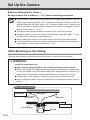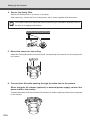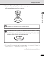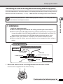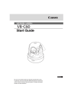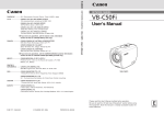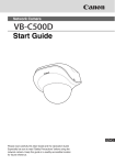
1
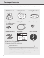
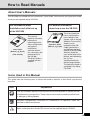
NETWORK CAMERA
Start Guide
Please read these Start Guide and Operation Guide carefully before operation.
Be sure to read the “a Safe Use of Equipment” section before using this
equipment. Store this manual in a readily accessible location for future reference.
Introduction
Thank you for purchasing the Canon Network Camera VB-C300 (hereafter referred to as the VBC300).
This User’s Manual describes how to set up and use the VB-C300. Read this Manual carefully before
using the VB-C300 to ensure effective operation. Make sure that you read the “a Safe Use of
Equipment” in this Manual, as well as the supplied CD-ROM ReadMe file.
For the latest information (firmware, software, manual and the hardware and software
requirements, etc.) please refer to our WebView Product web page: canon.com/webview
Exclusion of Liability
If the Product is connected to a recording device, Canon Inc. accepts no responsibility
whatsoever for any financial losses that may be incurred as a result of the loss of recorded
information or images, regardless of the internal or external cause of the loss.
On Copyrights
Videos, images or sounds taken or recorded with your VB-C300 may not be utilized or published,
without consent of copyright holders, if any, except in such a way as permitted for personal use
under relevant copyright law.
Notes
1. The unauthorized transfer of all or any part of the contents of this Manual is forbidden.
2. The contents of this Manual are subject to change without notice.
3. Every effort has been made to ensure that this Manual is flawless. However, if you find any
oversights, please let us know.
4. Notwithstanding the above, Canon accepts no responsibility for any effects resulting from the
use of this Manual.
Trademark Notices
●Canon and Canon logo are registered trademarks of Canon Inc.
●Microsoft and Windows are registered trademarks of Microsoft Corporation in the United States
and other countries.
●Windows is legally recognized as Microsoft Windows Operating System.
●Other brand or product names in this Manual may be trademarks or registered trademarks of
their respective companies.
WARNING : To reduce the risk of electric shock, do not expose this appliance to rain or
moisture.
ii
Introduction
Request concerning disclosure of videos and audio
With respect to the disclosure of videos and audio, we request that sufficient consideration
be given to matters of privacy and rights not to be photographed.
<Reference>
●Locate camera so that people cannot make special specifications.
●When videos are taken of specific buildings, interiors and the like, install the camera
only after receiving approval from the administrator.
Please note that the operator of the camera site and not Canon has full responsibility
regarding the disclosure of videos and audio.
Legal Notice
In some countries or regions, monitoring via a camera is banned by the law or regulation,
and the law or regulation depends on the country or region.
Before using the VB-C300, check the law or regulation of the country or region where the
camera is used.
Usage Notice of Audio
● The audio and video may be out of sync.
● The audio stream may be interrupted according to the performance of your PC and the
network environment.
● You can send audio and video to up to 15 clients. However, if there are a large number
of clients, the audio stream may be interrupted.
● The audio stream may be interrupted if you use anti-virus software.
● Disconnecting the LAN cable also disconnects audio. Reconnect to the camera from
the NC Viewer.
■ European Union (and EEA) only.
This symbol indicates that this product is not to be disposed of with your
household waste, according to the WEEE Directive (2002/96/EC) and your
national law. This product should be handed over to a designated collection
point, e.g., on an authorized one-for-one basis when you buy a new similar
product or to an authorized collection site for recycling waste electrical and
electronic equipment (EEE). Improper handling of this type of waste could have a possible
negative impact on the environment and human health due to potentially hazardous
substances that are generally associated with EEE. At the same time, your cooperation in
the correct disposal of this product will contribute to the effective usage of natural resources.
For more information about where you can drop off your waste equipment for recycling,
please contact your local city office, waste authority, approved WEEE scheme or your
household waste disposal service.
For more information regarding return and recycling of WEEE products, please visit
www.canon-europe.com/environment.
(EEA: Norway, Iceland and Liechtenstein)
© Copyright 2007 CANON INC.
ALL RIGHTS RESERVED
iii
Contents
Introduction ...................................................................................................... ii
Contents .......................................................................................................... iv
Package Contents ........................................................................................... vi
How to Read Manuals .................................................................................... vii
About User’s Manuals ................................................................................................ vii
Icons Used in this Manual .......................................................................................... vii
Safe Use of Equipment ................................................................................. viii
Maintenance ............................................................................................................. xiv
Chapter 1 Before Using the VB-C300
Features of the VB-C300 .............................................................................. 1-2
Operating Environment ................................................................................ 1-4
VB Initial Setup Tool Ver. 3.0 .................................................................................... 1-4
NC Viewer Ver. 1.0 ................................................................................................... 1-4
VBAdmin Tools Ver. 3.0 ........................................................................................... 1-5
Viewer Switcher Tool Ver. 1.0 .................................................................................. 1-5
System Components and Their Operation ................................................. 1-7
Options .......................................................................................................... 1-9
Indoor Dome Housing (VB-RD41S-C/S) (Optional) ................................................. 1-9
AC Adapter (PA-V17) (Optional) .............................................................................. 1-9
Network Video Recorder VK-64/VK-16 V1.3 (Optional) ......................................... 1-10
Chapter 2 Installing the Camera
Setup Workflow ............................................................................................. 2-2
Connect the Camera to the Network and Perform the Initial Setting ....... 2-4
Connect the Camera to the Network and Turn the Power Supply On ...................... 2-4
Initial setting of the Camera ..................................................................................... 2-7
Checking the Camera Connection ......................................................................... 2-10
Install the Software and View the Camera Video ..................................... 2-11
Install Necessary Software .................................................................................... 2-11
Viewing the Camera Video .................................................................................... 2-12
Set Up the Camera ...................................................................................... 2-14
When Mounting on the Ceiling ............................................................................... 2-14
When Mounting the Camera at Upright Position .................................................... 2-18
When Mounting the Camera on the Ceiling with
the Dome Housing (VB-RD41S-C/S) (Optional) ...................................................... 2-19
iv
Contents
Chapter 3 Appendix
External Dimensions .................................................................................... 3-2
VB-C300 .................................................................................................................. 3-2
Indoor Dome Housing (VB-RD41S-C/S) (Optional) ................................................. 3-2
Specifications ............................................................................................... 3-3
I/O Terminals .................................................................................................. 3-4
External Device I/O Terminals .................................................................................. 3-4
Audio I/O Terminals .................................................................................................. 3-6
Video Output Terminal (For maintenance) ............................................................... 3-6
v
Package Contents
The VB-C300 package contains the following items. If any of these items is missing, please contact
the retailer from which you purchased the product.
1. VB-C300 main unit
2. Ceiling Bracket
3. Ceiling Mount Cover
4. Screws (Four)
5. Safety Wire
6. Power Connector
8. Template
9. Setup CD-ROM
*For fixing the camera to
the Ceiling Bracket
7. Rubber Foot (Four)
10. Start Guide (This document)
11. Warranty Card (NTSC model only)
Setup CD-ROM Contents
ReadMe-J.txt (Japanese text containing precautions etc. other than those in this document)
ReadMe-E.txt (English text containing precautions etc. other than those in this document)
VBSetup.exe (Initial settings tool → P.2-7)*
MANUAL folder (PDF file for Start Guide and Operation Guide, Japanese and English versions ) *
VBTools folder (Bundled software installer set)*
* For the latest information such as the bundled software and manual,
please refer to our WebView Product web page: canon.com/webview
vi
How to Read Manuals
About User’s Manuals
The VB-C300 is provided with two documents; “Start Guide” (this manual) and “Operation Guide”
stored on the supplied Setup CD-ROM.
For information about
installation and initial set up
For detailed information
about how to use the VB-C300
of the VB-C300
Start Guide
(Manual_sg_E.pdf)
(This manual)
This manual
explains the safety
precautions,
operating environment, configuration
and options,
initialization,
software installation, mounting, and
specifications of
the VB-300.
The Start Guide is
supplied with the
product.
Operation Guide
(Manual_og_E.pdf)
This manual explains
how to configure the
basic settings of the
camera, how to use the
VBAdmin Tools and NC
Viewer, how to
troubleshoot the VBC300, specifications
and detailed operation
method of the VB-C300.
Sections where the
user should refer to this
Manual are indicated by
the d icon
accompanied by the
relevant page number.
The Operation Guide is
contained in the Setup
CD-ROM.
Icons Used in this Manual
This guide uses the following icons to attract the reader’s attention to text which is particularly
important.
Icon
Note
Tip
d
Explanation
This icon indicates important information that must be observed or actions that are
prohibited during an operation. These notes must be read to prevent possible faults
or damage to the equipment.
Indicates supplementary information or a reference to an operation. Users are
advised to read these memos.
Refer to the Operation Guide PDF manual on the supplied Setup CD-ROM.
vii
a Safe Use of Equipment
a
An exclamation point, within a triangle, is intended to alert the user to the presence of
important operating and maintenance (servicing) instructions in the literature
accompanying the equipment.
a Important Warnings
a CAUTION:
TO REDUCE THE RISK OF ELECTRIC SHOCK, DO NOT REMOVE COVER (OR
BACK). NO USER-SERVICEABLE PARTS INSIDE. REFER SERVICING TO
QUALIFIED SERVICE PERSONNEL.
The serial number of this equipment may be found on the bottom of the VB-C300.
No others have the same serial number as yours.
You should record the number and other vital information here and retain this book
as a permanent record of your purchase to aid identification in case of theft.
Date of Purchase
Dealer Purchased from
Dealer Address
Dealer Phone No.
Model No. VB-C300
Serial No.
For Users in the UK (PA-V17) (Optional)
When replacing the fuse only a correctly rated approved type should be used and
be sure to re-fit the fuse cover.
The AC adapter can be connected to the VB-C300 from a standard AC power
outlet. Please check your instruction manual to make sure that your
VB-C300 is compatible with this adapter.
– The socket-outlet should be installed near the equipment and should be easily
accessible.
– Unplug the apparatus from the wall outlet before cleaning or maintaining.
a Important Operational Instructions
a WARNING:
TO REDUCE THE RISK OF ELECTRIC SHOCK, DO NOT EXPOSE THIS
EQUIPMENT TO RAIN OR MOISTURE.
a CAUTION:
TO REDUCE THE RISK OF ELECTRIC SHOCK AND TO REDUCE ANNOYING
INTERFERENCE, USE THE RECOMMENDED ACCESSORIES ONLY.
viii
a Safe Use of Equipment
FDA regulation
This Network Camera has not been evaluated by the Food and Drug Administration
(FDA) for use as a medical device. When incorporated into a system with medical
applications, FDA regulations may apply. Therefore, please consult your legal
advisor to determine whether FDA regulations apply.
FCC NOTICE
Network Camera, Model Name: VB-C300NA, VB-C300PA
This device complies with Part 15 of the FCC Rules. Operation is subject to the
following two conditions: (1) This device may not cause harmful interference,
and (2) this device must accept any interference received, including interference
that may cause undesired operation.
Note: This equipment has been tested and found to comply with the limits for a
Class B digital device, pursuant to Part 15 of the FCC Rules. These limits are
designed to provide reasonable protection against harmful interference in a
residential installation. This equipment generates, uses and can radiate radio
frequency energy and, if not installed and used in accordance with the
instructions, may cause harmful interference to radio communications.
However, there is no guarantee that interference will not occur in a particular
installation. If this equipment does cause harmful interference to radio or
television reception, which can be determined by turning the equipment off and
on, the user is encouraged to try to correct the interference by one or more of
the following measures:
- Reorient or relocate the receiving antenna.
- Increase the separation between the equipment and receiver.
- Connect the equipment into an outlet on a circuit different from that to which
the receiver is connected.
- Consult the dealer or an experienced radio/TV technician for help.
Use of shielded cable is required to comply with class B limits in Subpart B of
Part 15 of FCC Rules.
Do not make any changes or modifications to the equipment unless otherwise
specified in the manual. If such changes or modifications should be made, you
could be required to stop operation of the equipment.
Canon U.S.A. Inc.
One Canon Plaza, Lake Success, NY 11042, U.S.A.
Tel No. (516) 328-5600
Canadian Radio Interference Regulations
This Class B digital apparatus complies with Canadian ICES-003.
Réglementation canadienne sur les intérferences radio
Cet appareil numérique de la classe B est conforme à la norme NMB-003 du
Canada.
Dieses Produkt ist zum Gebrauch im Wohnbereich, Geschäfts- und
Gewerbebereich sowie in Kleinbetrieben vorgesehen.
ix
a Safe Use of Equipment
a IMPORTANT SAFETY INSTRUCTIONS
In these safety instructions, the word
“equipment” refers to the Canon Network
Camera VB-C300 and all its accessories.
1. Read Instructions - All the safety and
operating instructions should be read before
the equipment is operated.
2. Retain Instructions - The safety and operating
instructions should be retained for future
reference.
3. Heed Warnings - All warnings on the
equipment and in the operating instructions
should be adhered to.
4. Follow Instructions - All operating and
maintenance instructions should be followed.
5. Cleaning - Unplug this equipment from the
wall outlet before cleaning.
Wipe the equipment with a clean soft cloth. If
necessary, put a cloth in diluted neutral
detergent and wring it well before wiping the
equipment with it. Finally, clean the
equipment with a clean dry cloth. Do not use
benzene, thinner or other volatile liquids or
pesticides as they may damage the product’s
finish. When using chemically-treated
cleaning cloths, observe those precautions
accordingly.
6. Accessories - Do not use accessories not
recommended in this Manual as they may
be hazardous. Always use specified
connection cables. Connect devices correctly.
7. Water and Moisture - Hazard of electric shock
- Do not use the equipment near water or in
rainy/moist situations. Do not put a heater
near this equipment.
8. Placing or Moving - Do not place on an
unstable cart, stand, tripod, bracket or table.
The equipment may fall, causing serious
injury to a child or adult, and serious damage
to the equipment. An
equipment
and
cart
combination should be moved
with care.
Quick stops, excessive force,
x
and uneven surfaces may cause the
equipment and cart combination to overturn.
9. Power Sources - The PA-V17 AC adapter
(optional) should be operated only from the type
of power source indicated on the marking label.
If you are not sure of the type of power supply to
your home, consult your equipment dealer or
local power company.
10. Polarization - The PA-V17 AC adapter (optional)
is equipped with a polarized 2-prong plug (a plug
having one blade wider than the other).
The 2-prong polarized plug will fit into the
power outlet only one way. This is a safety
feature. If you are unable to insert the plug
fully into the outlet, try reversing the plug. If
the plug still fails to fit, contact your electrician
to replace your obsolete outlet. Do not defeat
the safety purpose of the polarized plug.
11. Power Cord Protection - Power cords should
be routed so that they are not likely to be
walked on or pinched by items placed upon
or against them. Pay particular attention to
plugs and the point from which the cords exit
the equipment.
12. Outdoor Antenna Grounding - If an outside
antenna is connected to the equipment, be
sure the antenna is grounded so as to provide
some protection against voltage surges and
built-up static charges. Section 810 of the
National Electrical Code, ANSI/NFPA No.701984, provides information with respect to
proper grounding of the mast and supporting
structure, grounding of the lead-in wire to an
antenna discharge unit, size of grounding
conductors, location of antenna, antenna
discharge unit, connection to grounding
electrodes, and requirements for the
grounding electrode. See figure 1.
a Safe Use of Equipment
fig-1
EXAMPLE OF ANTENNA GROUNDING AS
PER NATIONAL ELECTRICAL CODE
ANTENNA
LEAD IN WIRE
GROUNDING
CLAMP
ELECTRIC
SERVICE
EQUIPMENT
ANTENNA
DISCHARGE
UNIT (NEC
SECTION 810-20)
a. When the power-supply cord or plug is
damaged.
GROUNDING
CONDUCTORS
(NEC SECTION
810-21)
b. If any liquid has been spilled onto, or
objects have fallen into, the equipment.
GROUNDING CLAMPS
NEC — NATIONAL ELECTRIC CODE
18. Damage Requiring Service - Disconnect this
equipment from the wall outlet and all power
sources including batteries, and refer
servicing to qualified service personnel under
the following conditions.
POWER SERVICE
GROUNDING ELECTRODE
SYSTEM
(NEC ART 250. PART H)
13. Lightning - For added protection of this
equipment during a lightning storm, or when
it is left unattended and unused for long
periods of time, disconnect it from the wall
outlet and disconnect the antenna. This will
prevent damage to the equipment due to
lightning and power-line surges.
14. Power Lines - An outside antenna system
should not be located in the vicinity of
overhead power lines or other electric light
or power circuits, or where it can fall into such
power lines or circuits. When installing an
outside antenna system, extreme care should
be taken to keep from touching such power
lines or circuits as contact with them might
be fatal.
15. Overloading - Do not overload wall outlets and
extension cords as this can result in a risk of
fire or electric shock.
16. Object and Liquid Entry - Never push objects
of any kind into this equipment through
openings as they may touch dangerous
voltage points or short out parts that could
result in a fire or electric shock. Be careful
not to spill liquid of any kind onto the
equipment.
17. Servicing - Do not attempt to service this
equipment yourself as opening or removing
covers may expose you to dangerous voltage
or other hazards. Refer all servicing to
qualified personnel.
c. If the equipment has been exposed to rain
or water.
d. If the equipment does not operate normally
even if you follow the operating instructions.
Adjust only those controls that are covered
by the operation instructions. Improper
adjustment of other controls may result in
damage and will often require extensive
work by a qualified technician to restore
the equipment to its normal operation.
e. If the equipment has been dropped or the
cabinet has been damaged.
f. When the equipment exhibits a distinct
change in performance. This indicates a
need for service.
19. Replacement Parts - When replacement parts
are required, be sure the service technician
has used replacement parts that are specified
by Canon or that have the same
characteristics as the original part.
Unauthorized substitutions may result in fire,
electric shock or other hazards.
20. Safety Check - Upon completion of any
service or repairs to this equipment, ask the
service technician to perform safety checks
to determine that the equipment is in safe
operating order.
21. Do not install the equipment in the following
locations as this can cause a fire or electric
shock:
- Hot locations
- Close to a fire
- Very humid or dusty locations
xi
a Safe Use of Equipment
- Locations exposed to direct sunlight
- Locations exposed to salt spray
- Close to flammable solvents (alcohol,
thinners, etc.)
22. When any of the following occurs,
immediately switch off the equipment, unplug
it from the main power supply and contact
your nearest Canon supplier. Do not continue
to use the equipment as this can cause a fire
or electric shock.
- The equipment emits any smoke, heat,
abnormal noise, or unusual odor.
- A metal object falls into the equipment.
- The equipment is damaged in some way.
23. Please observe the following when using the
equipment. Failure to do so can result in a
fire or electric shock.
- Do not use flammable sprays near the
equipment.
- Do not subject the equipment to strong
impacts.
24. Make sure the power line and network cable
are implemented in a safe manner
accordingly to the related technical
regulations.
25. Focusing on the direct sunlight, halogen
lamp or any other high-intensity lamp for a
long time may cause damage to the image
sensor.
26. This installation should be made by a qualified
service person and should confirm to all local
codes.
For CA, USA only
Included lithium battery contains Perchlorate Material - special handling may apply.
See www.dtsc.ca.gov/hazardouswaste/perchlorate/ for details.
xii
a Safe Use of Equipment
When using the camera with PoE HUB
a CAUTION:
● Use the PoE HUB or Midspan which is compliant with IEEE802.3af and has been
confirmed for the interoperability with the camera.
● Do not touch the tip of the LAN cable with a wet
hand.
● When the PoE HUB and AC adapter (optional) are
both connected to the camera, the PoE-supplied
power is used while it is active, and the power from
the AC adapter is not used.
● Although some PoE HUBs can limit the current used by each port, limiting may
prevent the camera from operating correctly. In this case, do not limit the current
for the port used by the camera.
● Some PoE HUBs have a limit on the total current consumption of the ports and
using multiple ports of a single hub may prevent the camera from operating
correctly. Check the manual of the PoE HUB used.
● Use a LAN cable conforming to Category 5 or higher standard (max. length:
100m).
● Use a shielded twisted-pair (STP) cable conforming to the EMC standard as the
LAN cable.
VB-C300
PoE HUB
LAN cable
Max. 100m
HUB
LAN cable
Midspan
(LAN cable power supply device)
VB-C300
* Similarly to the PoE HUB, a Midspan (LAN cable power supply device) supplies
power to the camera via the LAN cable.
xiii
a Safe Use of Equipment
Maintenance
Be sure to turn the power off before doing maintenance (➝ P.2-5).
Cleaning the Equipment
1. Carefully wipe the equipment with a soft cloth that has
been moistened with water or a mild detergent.
2. Wipe with a piece of dry cloth.
Cleaning the Lens
Use a commercially available lens cleaner to remove any soiling from the lens.
● The auto-focus may not function correctly if the surface of the lens is dirty.
● Scratches on the surface of the lens will cause video defects.
When using the Indoor Dome Housing (Optional)
The dome should be cleaned regularly because the video quality may get deteriorated if the
surface of the dome is dirty.
1. Remove the dome as directed in Steps 8 and 9 in “When Mounting the
Camera on the Ceiling with the Indoor Dome Housing (VB-RD41S-C/S)
(optional)” (➝ P.2-22).
2. Carefully wipe the dome with a soft cloth that has been moistened with
water or a mild detergent.
3. Wipe with a piece of dry cloth.
4. Attach the dome as directed in Steps 8 and 9 in “When Mounting the Camera
on the Ceiling with the Indoor Dome Housing (VB-RD41S-C/S) (optional)”
(➝ P.2-22).
xiv
Chapter
Before Using the VB-C300
This chapter describes the features of the VB-C300, the
hardware and software requirements, and the name and
functions of the system components.
Features of the VB-C300
The VB-C300 is a network camera integrating a camera and server functions into a compact form
factor.
AF Zoom lens with horizontal viewing angle of 70° and pan/tilt functions
The VB-C300 has a zoom lens with horizontal viewing angle of 70° and optical 2.4X (and digital 4X)
zoom lens which can capture a wide range at a time. In addition to a bird’s eye view of the entire area,
the VB-C300 can capture a wide-angle image even if it is close to the object. The VB-C300 has the AF
capability as well as pan and tilt functions to move the camera horizontally and vertically, allowing
easy adjustment of the viewing angle when the layout of the target area is changed. These functions
are also useful when monitoring the situation by remote-controlling the camera.
High-quality video of moving objects
The VB-C300 uses the progressive-scan CCD to allow capturing noise-less high quality images
of moving objects.
Color capturing under 1 lux and auto Day & Night
The VB-C300 can capture color images under as dark as 1 lux (NTSC: 1/30 sec. PAL: 1/25 sec.)
in the Day mode and monochrome images under as dark as 0.25 lux (NTSC: 1/30 sec. PAL: 1/25
sec.) in the Night mode (by disabling the infrared cut filter).The VB-C300 also has the Day &
Night switching function* (→ dOperation Guide P.1-10) to automatically switch between color
capturing under bright conditions during daytime and monochrome capturing under dark conditions
during nighttime, making the camera suitable for monitoring at locations where environmental
brightness changes during a day.
* A through test is required in advance to use the Day & Night switching function.
Video distribution server function
Motion-JPEG type is used to compress video images to enable distribution of high-quality videos
at a high frame rate (NTSC: up to 30 fps, PAL: up to 25 fps*) with VGA (640 x 480) size. Up to 15
clients can view video at the same time from a single VB-C300.
* The frame rate may be decreased depending on the Viewer PC’s capability or network traffic.
Camera position presets
By saving frequently-used camera settings such as camera head aim and zoom position as presets,
you can control the camera from the NC Viewer by simply selecting a desired preset. Up to 20
presets can be set (→ dOperation Guide P.2-10).
Panorama Image Creation function and various settings
The full view of the area that camera covers can be registered as a panorama image. You can
define presets visually and easily by using a registered panorama image.
Transmission and reception of audio (full duplex)
You can send and receive audio via the NC Viewer (full duplex) by connecting a microphone and
speaker with amp to the camera*.
* The microphone and speaker are sold separately.
1-2
Features of the VB-C300
Upright Position and Ceiling Mount
Before Using the VB-C300
The VB-C300 can be mounted at the upright position or on the ceiling by simply changing settings
(→ dOperation Guide P.1-9).
* The camera cannot be installed in locations subject to direct sunlight, high temperatures, high
humidity, or other adverse conditions (→ P.x).
Compact and Stylish Design
The camera’s stylish design fits various environments as a part of construction or interior. Also
the supplied ceiling mount cover will hide the ceiling bracket and cables (→ P.vi) when mounting
the camera on the ceiling.
PoE Function
The camera is capable of the PoE function to transfer video/audio data and supply power via a
LAN cable connected to a PoE* HUB (→ P.xiii). You do not have to prepare power supply if you
connect the camera to a PoE HUB.
*Power over Ethernet. Compliant with the IEEE 802.3af standard by the Institute of Electrical and
Electronic Engineers.
Up to 100 m of the LAN cable can be connected between the camera and the PoE HUB (→ P.xiii).
Shade Correction Function (NC Viewer)
If the background of an image is bright, making the subject difficult to see, you can adjust the
contrast of the darker areas to make it easier to see. Unlike backlight compensation, the shade
correction feature allows image processing without adversely affecting the existing lighter regions
(→ dOperation Guide P.3-29).
Optional Indoor Dome Housing for Various Mounting Options
You can use the optional indoor dome housing (→ P.1-9). Two types of dome housing are provided.
The Smoke type hides the presence of the camera and the Clear type appeals the presence of
the camera while protecting it from dusts. You can install the camera as a dome camera and
allow various mounting options.
Monitoring Videos from Multiple Locations using Optional Recording Software
You can use the optional recording software “Network Video Recorder VK-64/VK-16 V1.3” (→ P.1-10)
to build a video monitoring system consisting of the network cameras installed at multiple locations.
1-3
Operating Environment
For the latest information (firmware, supplied software, manual and the hardware and
software requirements, etc.), please refer to our WebView Product web page: canon.com/
webview
VB Initial Setup Tool Ver. 3.0 (→ P.2-7)
This tool is for performing initial settings for the VB-C300.
Operating System/
Web Browser
Windows 2000 Professional (SP4)/Microsoft Internet Explorer 6.0 (SP1)
Windows XP (SP1a)/Microsoft Internet Explorer 6.0 (SP1)
Windows XP (SP2)/Microsoft Internet Explorer 6.0 (SP2)
Windows Server 2003 Standard Edition/Microsoft Internet Explorer 6.0
Windows Server 2003 Standard Edition (SP1)/Microsoft Internet Explorer 6.0 (SP1)
Windows Server 2003 R2 Standard Edition (SP1)/Microsoft Internet Explorer 6.0 (SP1)
NC Viewer Ver. 1.0 (→ d Operation Guide P.3-2)
The viewer software that is supplied with the VB-C300. You can view the video captured by the
VB-C300 and control the camera.
Operating System/
Web Browser
Windows 2000 Professional (SP4)/Microsoft Internet Explorer 6.0 (SP1)
Windows XP (SP1a)/Microsoft Internet Explorer 6.0 (SP1)
Windows XP (SP2)/Microsoft Internet Explorer 6.0 (SP2)
Windows Server 2003 Standard Edition/Microsoft Internet Explorer 6.0
Windows Server 2003 Standard Edition (SP1)/Microsoft Internet Explorer 6.0 (SP1)
Windows Server 2003 R2 Standard Edition (SP1)/Microsoft Internet Explorer 6.0 (SP1)
* Must be installed from the supplied Setup CD-ROM in advance (→ P.2-11).
Note
1-4
When using the VB-C300 with the VB-C50 series, install the Viewer for PC supplied
with the VB-C50 series camera.
Operating Environment
VBAdmin Tools Ver. 3.0 (→ d Operation Guide P.2-2)
Use the VBAdmin Tools to create panoramas, set presets, view logs, and configure the NC Viewer.
Windows 2000 professional (SP4)/Microsoft Internet Explorer 6.0 (SP1)
Windows XP (SP1a)/Microsoft Internet Explorer 6.0 (SP1)
Windows XP (SP2)/Microsoft Internet Explorer 6.0 (SP2)
Windows Server 2003 Standard Edition/Microsoft Internet Explorer 6.0
Windows Server 2003 Standard Edition (SP1)/Microsoft Internet Explorer 6.0 (SP1)
Windows Server 2003 R2 Standard Edition/Microsoft Internet Explorer 6.0 (SP1)
Before Using the VB-C300
Operating System/
Web Browser
* Must be installed from the supplied Setup CD-ROM (→ P.2-11).
Note
If the VB-C300 is used with VB-C50 series, first install the VB Administration Tools
for the VB-C50 series, then install the VBAdmin Tools, for the VB-C300.
Viewer Switcher Tool Ver. 1.0 (→ dOperation Guide P.3-34)
This tool switches the NC Viewer and the Viewer for PC for the VB-C50 series camera.
Operating System/
Web Browser
Windows 2000 professional (SP4)/Microsoft Internet Explorer 6.0 (SP1)
Windows XP (SP1a)/Microsoft Internet Explorer 6.0 (SP1)
Windows XP (SP2)/Microsoft Internet Explorer 6.0 (SP2)
Windows Server 2003 Standard Edition/Microsoft Internet Explorer 6.0
Windows Server 2003 Standard Edition (SP1)/Microsoft Internet Explorer 6.0 (SP1)
Windows Server 2003 R2 Standard Edition/Microsoft Internet Explorer 6.0 (SP1)
* Must be installed from the supplied Setup CD-ROM (→ P.2-11).
Note on Windows XP SP2
Note
If you start the VB Initial Setup Tool from a Windows XP SP2 PC, the Windows
Security Alert dialog may appear.
If the Windows Security Alert dialog appears, click “Unblock”.
Once you click “Unblock”, the dialog box will not be displayed again.
1-5
Operating Environment
Note on Windows Server 2003
Note
With Windows Server 2003 Standard Edition running Microsoft Internet Explorer 6.0 and
Windows Server 2003 Standard Edition (SP1) running Microsoft Internet Explorer 6.0 (SP1),
the default security level for the Internet or intranet sites in Internet Explorer is “High”.
As a result, windows such as the settings window do not function normally unless you first
register the site in the contents block dialog box that appears when you access the camera’s
top page (→ P.2-10). Register the site to ensure normal functioning.
1. When you access the camera server
top page in Internet Explorer, the
dialog box appears.
2. Click “Add”. The dialog box for
adding Trusted sites appears.
3. Enter the IP address of the VB-C300 in the “Add this Web site to the
zone” box and then click “Add” to register the camera as a trusted site.
For more information on registering trusted sites, click “Learn more about Internet
Explorer’s Enhanced Security Configuration...” in the dialog box in step 1 and refer to
the summary provided.
If you have enabled the Windows firewall settings with Windows Server 2003 Standard
Edition (SP1), please refer to the “Note on Windows XP SP2” (→ P.1-5) and follow the
instructions.
1-6
System Components and Their Operation
Front
Before Using the VB-C300
Lens
AF Zoom lens with horizontal viewing
angle of 70°
Camera head
Head arm
LED
Lights in blue.
• Blinking - When the power is turned
on, the camera has been
rebooted, or the camera
is not connected to the
network.
• Continuously lights Normal operation
When LED is set to turn
OFF (→dOperation
Guide P.1-19).
* Even if the LED is set to turn OFF, it
flashes for several seconds then
turns OFF when the power supply is
turned ON or the VB-C300 has been
rebooted.
• Off -
Rear
100/10 BT LAN connector
(100Base-TX/10Base-T Auto-Negotiation)
Capable of PoE power supply
(compliant with IEEE 802.3af)
Video output terminal (For maintenance)
OUT IN-2 IN-1
DC IN 12-13V
AC IN 24V
100/10BT
LINE
IN
External Device I/O Terminals (→ P.3-4)
LINE
OUT
VIDEO
OUT
BA
Safety wire attachment
Audio output terminal (LINE OUT)
Audio input terminal (LINE IN)
Power connection socket (→ P.2-6)
1-7
System Components and Their Operation
Bottom
On the bottom of the VB-C300 there are the MAC address required for network settings, a Reset
switch that initializes settings and the serial number.
Screw hole for
Ceiling Bracket
Model Name
NTSC VB-C300NA
PAL
Reset switch
You can initialize settings
by pressing this button
with a thin-tipped object
while turning on the power
switch, and keeping the
button pressed for more
than five seconds after
turning on.
Screw hole for tripod mounting
1-8
VB-C300PA
Serial No.
The serial number for
this unit is shown
here.
MAC address
Address unique to this
camera. Please make a
note before installing this
unit (→ P.2-8).
Options
Indoor Dome Housing (VB-RD41S-C/S) (Optional)
Before Using the VB-C300
The Indoor Dome Housing (VB-RD41S-C/S) (optional) is a dome housing dedicated to the VBC300. Two color types are available; clear type (VB-RD41S-C) and smoked type (VB-RD41S-S).
Use the dome to embedded the camera in the ceiling for neat installation.
Please note that the Indoor Dome Housing (VB-RD41S-C/S) is an optional product and is therefore
sold separately.
Using example
Smoked type (VB-RD41S-S)
• Light transmittance: approx. 50%
• Minimum subject illumination:
Day mode: 2 lux
(NTSC: 1/30 sec. PAL: 1/25 sec., color)
Night mode: 0.5 lux
(NTSC: 1/30 sec. PAL: 1/25 sec., monochrome)
AC Adapter (PA-V17) (Optional)
This is an AC adapter dedicated to the VB-C300. Use the AC adapter when the PoE HUB is not
used. This adapter is not supplied with the product and must be purchased separately.
1-9
Options
Network Video Recorder VK-64/VK-16 V1.3 (Optional)
VK-64/VK-16 is a software program to view and record video images distributed from the network
camera.
The VB-C300 is only supported by V1.3. It is useful when using multiple network cameras.
VK-64/VK-16 Screen Example
Note
1-10
The VB-C300 is not supported by the older versions of VK-64/VK-16. If using an
older version, you need to upgrade VK-64/VK-16 to the latest version. Visit our Web
site for the details.
WebView Product web page: canon.com/webview
Chapter
Installing the Camera
This chapter explains how to install the camera.
First, connect the camera to the network, and perform the
initial setting.
Next, install the software and view the video with the NC
Viewer.
Finally, mount the camera at the desired place.
Please set the camera IP
address before installing the
camera.
Setup Workflow
The flow for setting up the camera and view the camera video involves; connecting the camera
with the PC over the network via a HUB and perform the initial settings. Installing the necessary
software on the PC, and checking to see if you can see video from the camera. Mounting the
camera, and the reboot.
1 Connect the camera to the network and perform the initial setting
Connect the camera to the PC via a HUB (→ P.2-4).
Please ask our sales person when using the PoE HUB and Midspan.
Use a shielded twisted-pair (STP) cable conforming to the EMC standard as the LAN cable.
Insert the supplied Setup CD-ROM into your PC and perform the initial setting (→ P.2-7).
VB-C300
LAN cable
Supplied Setup CD-ROM
HUB
2 Install the software and view the camera video
Install the necessary software (→ P.2-11).
2-2
Setup Workflow
Installing the Camera
3 Set Up the Camera
Mount the camera.
Install the camera securely (→ P.2-14).
Next, use the NC Viewer to view the camera
video (→ P.2-12).
2-3
Connect the Camera to the Network and Perform the Initial Setting
Connect the Camera to the Network and Turn the Power Supply On
First, connect the camera to the network. Connect the camera and PC via the HUB with a LAN
cable, connect the camera to the network, then turn the power on. If 20 minutes have passed since
the VB-C300 was turned on, it can no longer be detected by the VB Initial Setup Tool (➝ P.2-7). In
this case, turn the camera OFF then ON again.
The VB-C300 is equipped with the PoE (Power over Ethernet) function. The power can be supplied
to the camera via the LAN cable from an IEEE 802.3af-compliant PoE HUB.
When using PoE HUB
(Rear)
AC power cable
OUT IN-2 IN-1
DC IN 12-13V
AC IN 24V
LINE
OUT
LINE
IN
100/10BT
BA
VIDEO
OUT
Notebook PC
PoE HUB
LAN cable
When using the AC adapter (optional) or external power supply, connect them as shown below.
When using the AC Adapter (Optional) or external power supply
(Rear)
OUT IN-2 IN-1
AC power cable
DC IN 12-13V
AC IN 24V
LINE
OUT
LINE
IN
100/10BT
VIDEO
OUT
HUB
BA
Notebook PC
LAN cable
AC Adapter
2-4
The figure shows the AC adapter (optional).
Connect the Camera to the Network and Perform the Initial Setting
Note
Installing the Camera
● Please ask our sales person for PoE HUB and Midspan.
● Read the manual of the PoE HUB or Midspan for how to use it.
● Up to 100 m of the LAN cable can be connected between the camera and the PoE
HUB.
● Use a shielded twisted-pair (STP) cable conforming to the EMS standard as the
LAN cable.
● If the camera is connected to a switching HUB and connection is changed while
the camera is operating, the learning capability of the HUB may disturb the
communication. Do not change connection while the camera is operating.
Turning the Power ON and OFF
The VB-C300 itself does not have a power switch.
If the power is supplied to the VB-C300 via a LAN cable using the PoE function, connect and
disconnect the LAN cable from the camera to an operating HUB to turn the power ON and OFF.
When using PoE HUB
VB-C300
PoE HUB
LAN cable
When using the AC adapter (optional) or external power supply, the camera is powered ON by
plugging the AC adapter (optional) or external power supply.
When using the AC Adapter (Optional) or external power supply
VB-C300
100-240VAC 50/60Hz
AC Adapter
AC power cable
The figure shows the AC adapter (optional).
2-5
Connect the Camera to the Network and Perform the Initial Setting
When using external power supply
When using external power supply, use the Power
Connector (→ P.vi) supplied with the camera.
Connect the cables as shown to the right when using
the supplied Power Connector.
Supply 12VDC or 24VAC from a power supply
insulated from 100-240VAC supply. You can connect
12VDC power supply without regard to the polarity.
Screwdriver
Stripping length
approx. 4mm - 6mm
(0.16inch - 0.24inch)
Power
Connector
(Supplied)
Recommended power supply cables for VB-C300 [for reference]
Cable (AWG)
Conductor diameter
(ømm)
#24
(0.52mm)
(0.020inch)
#22
(0.65mm)
(0.026inch)
#20
(0.82mm)
(0.032inch)
#18
(1.03mm)
(0.041inch)
#16
(1.30mm)
(0.052inch)
12VDC
Maximum cable length (m)
Maximum cable length (ft)
5
16.4
9
29.5
14
45.9
23
75.5
32
104.9
24VAC
Maximum cable length (m)
Maximum cable length (ft)
11
36.1
18
59.1
29
95.1
46
150.9
64
210.0
Voltage range for power supply
12VDC: 10.8V - 13.2V
24VAC: 22.8V - 25.2V
Use a UL cable (equivalent to UL-1015) as the power cable for 12VDC or 24VAC.
Note
● The camera head position is automatically initialized when the power supply is
turned ON.
● Never touch the camera head while its position is being initialized. If you touch it,
the head position may not be initialized correctly, or other malfunctions may result.
● Wait at least 5 seconds before turning the power back on after shutting it off. Turning
it on too quickly may result in a malfunction. Observe the precautions given in
“Safe Use of Equipment/IMPORTANT SAFETY INSTRUCTIONS (→ P.viii, x), “Safe
Use of Equipment/When using the camera with PoE HUB (→ P.xiii) when plugging
and unplugging the power cable.
● Read the manual of the PoE HUB for how to power it ON or OFF.
● You can connect the AC adapter (optional) to the camera while it is powered from the
PoE HUB. In this case, the PoE-supplied power is used while it is active, and the
power from the AC adapter (optional) is not used. When the PoE-supplied power is
disconnected, the power supply automatically switches to the AC adapter (optional).
The network connection is now complete.
2-6
Connect the Camera to the Network and Perform the Initial Setting
Initial setting of the Camera
The instructions here assumes that a single camera is connected to a PC as an example.
Installation Example
VB-C300
Installing the Camera
LAN cable
HUB
1. Insert the supplied Setup CD-ROM into your PC, and double-click
“VBSetup.exe” from Explorer to start the VB Initial Setup Tool.
Supplied Setup CD-ROM
○○○○○○○○○
Continued on the following page. a
2-7
Connect the Camera to the Network and Perform the Initial Setting
2. The VB Initial Setup Tool automatically
detects the camera connected to the
network, and displays its MAC address,
IP address, and model name.
Click to select
The factory default IP address is set to
“192.168.100.1”
The MAC address can be found on the label
attached on the bottom of the unit.
Note that VB Initial Setup Tool (VBSetup.exe)
cannot be used across subnets.
Click the MAC address to select it, and click
“Initial Setup”.
3. Enter the user name “root” and the
factory default password “VB-C300”
(case sensitive) then enter the IP
address and subnet mask.
If you do not want to specify a default gateway
address, disable the “Enter a Default Gateway
Address” box.
Once you have entered your settings, click “OK”.
Note
Tip
2-8
For Windows XP SP2 users, see “Note on Windows XP SP2” (→ P.1-5). This Note
holds true for users who have turned on Windows Firewall with Windows Server
2003 Standard Edition (SP1).
● The factory default password is “VB-C300.” Be sure to change it to ensure security
(→ dOperation Guide P.1-6).
● The MAC address for this unit is shown on the bottom of the VB-C300 (→ P.1-8).
● The IP address 192.168.100.1 is used as the factory default setting. Please set an
IP address that suits the environment in which the VB-300 is to be used.
Connect the Camera to the Network and Perform the Initial Setting
4. A setup progress window appears and
your settings will be saved.
Installing the Camera
5. Click “OK”.
Note
● Set the IP address to a value that suits your environment.
● Where the IP address has been automatically obtained from the DHCP server, you
cannot change the IP address setting from the VB Initial Setup Tool. Change the IP
address from the Network Settings page (→ dOperation Guide P.1-7).
● Please consult with your network administrator for the IP address, subnet mask
and default gateway address settings.
● If 20 minutes or more have passed since the VB-C300 was turned on, the VBC300 stops sending requests for IP addresses allocation and they cannot be
detected using the VB Initial Setup Tool. In this case, turn the camera OFF then
ON again.
● To restore the factory default settings, refer to “Restoring the Factory Default
Settings” in the Operation Guide (→ dOperation Guide P.4-8).
Initial settings are now complete.
2-9
Connect the Camera to the Network and Perform the Initial Setting
Checking the Camera Connection
When you have completed the initial setup, check that the VB-C300 is recognized correctly.
1. Click to select the MAC address you
want to check connection of and then
click “Settings”.
2. Your Web browser starts up and the
top page of the camera appears.
If this page appears, the camera is recognized
correctly.
For Windows Server 2003 users, see “Note on Windows Server 2003” (→ P.1-6).
Note
Tip
● If an authorized user is registered, a screen which asks for user name and password
appears when the top page is accessed.
● You can click “Settings” to set the configuration and preferences of the camera (→
dOperation Guide P.1-2).
Connection checking is now complete.
2-10
Installing the Software and View the Camera Video
Install Necessary Software
Install software to control the camera and view video from the camera. There are three types of
software you can install.
Software supplied with VB-C300
Type
NC Viewer
Viewer Switcher
Note
Installing the Camera
VBAdmin Tools
Description
Software for managing the camera (→dOperation Guide,
Chapter 2). Only the Administrator needs to install.
Viewer dedicated to the VB-C300. Administrator privilege and
Authorized User (with limited functionality) privilege are
available (→dOperation Guide, Chapter 3).
Switches the NC Viewer and the Viewer for PC which displays
video from the VB-C50i series camera (→dOperation Guide,
Chapter 3).
Install the software as directed below when using the VB-C300 and VB-C50 series
cameras together.
● First install the VB Administration Tools supplied with the VB-C50 series camera,
then install the VBAdmin Tools supplied with the VB-C300.
● Install the Viewer for PC supplied with the VB-C50 series camera.
1. Insert the supplied Setup CD-ROM into the CD-ROM drive of your PC and
follow the steps below.
1 Check that all other applications are closed, and select “My Computer” from the Start
menu bar.
On Windows 2000, double-click the My Computer icon on the desktop.
2 Double-click the CD-ROM icon displayed, VBTools folder, then “VBToolsInstall.exe” to
start the installation.
2. Once the starting screen has
appeared, select the installation
method and start installation.
Easy Installation:
VBAdmin Tools and NC
Viewer are automatically
installed.
Custom Installation: You can select software
to install.
2-11
Installing the Software and View the Camera Video
3. New icon for the installed software are created on the desktop after the
installation.
Tip
You cannot select the VBAdmin Tools only with Custom Installation (the NC Viewer
will also be installed).
Installation is now complete.
Viewing the Camera Video
The following steps is just for viewing the camera video using the NC Viewer. For the detailed
explanation on how to use the NC Viewer, see the Operation Guide (→ dOperation Guide P.3-2).
1. Double-click the NC Viewer icon on the desktop.
2. The NC Viewer starts and displays its
top menu.
3. Choose “Connect” from the File menu
bar to connect to the camera.
2-12
Installing the Software and View the Camera Video
4. A dialog box to connect the camera
appears.
Enter the IP address specified in the initial
setting in the Host Name field, “root” in the User
Name field, and “VB-C300” in the Password
field, then click “OK” to connect to the camera.
* “root” is a Administrator account of the camera.
Installing the Camera
Tip
● It is strongly recommended not to tick the Remember password box if the Administrator
and authorized user use the same PC.
● Be sure to change the Administrator password to ensure security (→ dOperation
Guide P.1-6).
5. Your PC is connected to the camera
and the video is displayed.
6. Camera connection check is complete if the video is displayed correctly.
Viewing the video is now complete.
2-13
Set Up the Camera
Before Setting Up the Camera
Be sure to define the IP address (→ P.2-7) before installing the camera.
Note
● If 20 minutes or more have passed since the VB-C300 was turned on, the VBC300 stops sending requests for IP addresses allocation and they cannot be
detected using the VB Initial Setup Tool. Therefore, specify the IP address and
confirm the camera operation before setting up the camera as directed in “Initial
setting of the Camera” (→ P.2-7).
● The permissible camera installation angles are ±20° from the horizontal.
● The MAC address for this unit is shown on the bottom of the VB-C300 (→ P.1-8).
Please make a note before installing this unit.
● When holding the camera, hold it with the head arm but not the camera head.
● The unit cannot be installed in locations subject to direct sunlight, high temperatures,
high humidity, or other adverse conditions (→ P.x).
When Mounting on the Ceiling
Follow the steps below to mount the camera on the ceiling. Install the camera securely.
a WARNING:
Install the camera securely.
● When installing the VB-C300 on the ceiling, contact your Canon dealer.
● When installing the VB-C300 on the ceiling, check that the ceiling is strong enough
to bear the weight of the VB-C300 including the Ceiling Bracket. Installation in a
weak location could result in the VB-C300 falling and causing serious injury.
● At least once a year, check for looseness in the camera installation mount.
● When routing the cables, pay much attention not to damage the indoor wiring or
piping.
Side View of mounting
Roof space
Safety Wire
Fix to an anchor
or structure
LAN cable
VIDEO
OUT
100/10BT
DC IN 12-13V
AC IN 24V
Ceiling board
LINE
IN
BA
LINE
OUT
OUT IN-2 IN-1
Ceiling Bracket
VB-C300
2-14
Setting Up the Camera
1. Mount the camera to the Ceiling Bracket with the supplied four screws.
Installing the Camera
VIDE
O
OUT
100/10BT
LINE
IN
B A
LINE
OUT
OUT
IN-2
IN-1
DC IN 12-13V
AC IN 24V
2. Use the supplied Template to determine the mounting location of the camera.
Considering the camera orientation, determine the mounting screw and cable hole locations
and mark them with a pencil.
Distance between screws: 147mm (5.79inch)
Screw hole diameter:
5.0mm (0.20inch) across
3. Drill two mounting screw holes and one cable hole on the ceiling.
Note
When using the AC adapter (optional), be sure to drill the cable hole to be large
enough so that the ferrite core of the cable can pass it.
○○○○○○○○○
Continued on the following page. a
2-15
Setting Up the Camera
4. Secure the Safety Wire.
Secure the Safety Wire to an anchor or structure.
After securing it, attach and fix it to the camera with a screw supplied with the camera.
VIDEO
OUT
LINE
IN
Note
If the cable hole cannot be drilled, because the ceiling is concrete for example, secure
the wire to an appropriate location.
BA
LINE
OUT
OUT IN-2 IN-1
5. Mount the camera on the ceiling.
Adjust the Ceiling Bracket to the screw holes on the ceiling, then secure it to the ceiling with
two screws.
VIDEO
OUT
100/10BT
DC IN 12-13V
AC IN 24V
LINE
IN
BA
LINE
OUT
OUT IN-2 IN-1
6. Connect the LAN cable passing through the cable hole to the camera.
When using the AC adapter (optional) or external power supply, connect the
power cable to the camera.
Connect the cables to External Device I/O terminals or Audio output/input terminals as required
to the camera.
VIDEO
OUT
100/10BT
DC IN 12-13V
AC IN 24V
LINE
IN
BA
LINE
OUT
OUT IN-2 IN-1
2-16
Setting Up the Camera
7. Attach the Ceiling Mount Cover to the camera.
Align the mark (o) on the Ceiling Mount Cover with the LED of the camera, and rotate the
cover counterclockwise to the mark (I) to secure it.
Installing the Camera
Ensure that the Ceiling Mount Cover is attached securely.
Note
Tip
If the cables cannot be fit in the roof space, because the ceiling is concrete for example,
or they cannot be in the Ceiling Mount Cover, cut the notch of the Ceiling Mount
Cover with a plier to provide a notch to pass the cables through. In this case, attach
the Ceiling Mount Cover first, then connect the cables.
8. When you finished mounting the camera, reboot the camera to initialize the
camera position (→ dOperation Guide P.1-20).
○○○○○○○○
Mounting is now complete.
2-17
Setting Up the Camera
When Mounting the Camera at Upright Position
Note
● Observe the precautions in “Before Setting Up the Camera” (→ P.2-14) and follow
them before mounting the camera.
● The shooting position of the VB-C300 is set on the assumption that the camera is
mounted at the inverted position. To reverse the camera video image upside down,
see “Setting Image Size, Quality and Camera Control (Video and Camera)” in the
Operation Guide (→ dOperation Guide P.1-8).
Mounting the Camera at a Flat Location
Attach the Rubber Feet to the camera.
Place the VB-C300 at a flat and stable location.
VIDEO
OUT
100/10B
DC IN
12-13V
AC IN 24V
T
LINE
IN
B A
LINE
OUT
OUT IN-2
IN-1
Using a Tripod
The screw hole for mounting a tripod is on the bottom of the VB-C300 toward the center.
Note
2-18
● Do not overtighten the mounting screw.
If excessive force is used to tighten the mounting
screw, camera head movement may be impeded,
or other malfunctions may result.
● Always use a tripod mounting screw that is less
than 5.5 mm (0.22 in.) in length. The use of screws
5.5 mm (0.22 in.) long or longer could damage the
camera. Also, the tripod seat used should be at
least 30 mm (1.18 in.) in diameter.
30mm
(1.18inch)
or wider
5.5mm
(0.22inch)
or shorter
Tripod
mounting
screw
Setting Up the Camera
When Mounting the Camera on the Ceiling with the Dome Housing (VB-RD41S-C/S) (Optional)
Follow the steps below to mount the camera on the ceiling with the Indoor Dome Housing (optional).
See the outer view of the dome (→ P.3-2) to determine the mounting position and orientation.
Installing the Camera
Note
Observe the precautions in “Before Setting Up the Camera” (→ P.2-14) and follow
them before mounting the camera.
a WARNING:
Install the camera securely.
● When installing the VB-C300 on the ceiling, contact your Canon dealer.
● When installing the VB-C300 on the ceiling, check that the ceiling is strong enough
to bear the weight of the VB-C300 including the In-Ceiling Bracket. Installation in a
weak location could result in the VB-C300 falling and causing serious injury.
● At least once a year, check for looseness in the camera installation mount.
● When routing the cables, pay much attention not to damage the indoor wiring or
piping.
Side View of mounting
Safety Wire
Roof space
Fix to an anchor
or structure
LAN cable
VIDEO
OUT
100/10BT
DC IN 12-13V
AC IN 24V
LINE
IN
BA
LINE
OUT
In-Ceiling Bracket
Backside Ceiling Bracket
OUT IN-2 IN-1
VB-C300
Ceiling board
Dome
1. Mount the camera to the In-Ceiling Bracket with the four screws.
Use the screws supplied with the Dome Housing.
○○○○○○○○○
Continued on the following page. a
2-19
VIDEO
OUT
100/10BT
DC IN 12-13V
AC IN 24V
LINE
IN
B A
LINE
OUT
OUT
IN-2
IN-1
Setting Up the Camera
2. Determine the mounting position of the camera.
Aligning with the camera orientation, determine the screw hole locations for the Backside
Ceiling Bracket and the hole location for the In-Ceiling Bracket, then mark them with a pencil.
(Mounting dimensions)
• Screw hole diameter: 6.5mm (0.26inch) across
3. Drill three mounting screw holes for the Backside Ceiling Bracket and a hole
for the In-Ceiling Bracket on the ceiling.
Note
After drilling the holes, clean the mounting location so that drilled refuse may not
enter the inside of the dome when installing the Indoor Dome Housing.
4. Mount the Backside Ceiling Bracket on the back side of the ceiling.
Tip
It is recommended to temporarily secure the Backside Ceiling Bracket with a twosided tape to the ceiling, so that it may not get loose when the dome is mounted on
the ceiling.
Insert the female parts on the Backside Ceiling Bracket into the holes drilled in step 3.
2-20
Setting Up the Camera
5. Secure the Safety Wire.
Secure the Safety Wire to an anchor or structure.
After securing it, attach and fix it to the camera with a screw supplied with the camera.
Installing the Camera
VIDEO
OUT
LINE
IN
BA
LINE
OUT
OUT IN-2 IN-1
6. Connect the LAN cable passing through the cable hole to the camera.
When using the AC adapter (optional) or external power supply, connect the
power cable to the camera.
Connect the cables to External Device I/O terminals or Audio output/input terminals as required
to the camera.
VIDEO
OUT
100/10BT
LINE
IN
DC IN 12-13V
AC IN 24V
BA
LINE
OUT
OUT IN-2 IN-1
7. Mount the In-Ceiling Bracket to the ceiling.
Insert the screws through the In-Ceiling Bracket and mount the In-Ceiling Bracket to the female
parts of the roof space fittings.
VIDEO
OUT
100/10BT
DC IN 12-13V
AC IN 24V
LINE
IN
BA
LINE
OUT
OUT IN-2 IN-1
○○○○○○○○○
Continued on the following page. a
2-21
Setting Up the Camera
8. Mount the dome.
Align the mark (o) on the dome with the mark (I) of the In-Ceiling Bracket, and rotate the dome
counterclockwise to the mark (I) to align the mounting screw holes to the mounting locations.
9. Fix the dome with a screw to prevent the dome from rotating.
10. When you finished mounting the camera, reboot the camera to initialize the
camera position (→ dOperation Guide P.1-20).
Tip
If the LED is turned ON, its light may be reflected by the dome and caught by the
camera. In this case, change the LED setting to “Turn the LED OFF.” (→dOperation
Guide P.1-19).
○○○○○○○○
Mounting is now complete.
2-22
Chapter
Appendix
This appendix shows the external dimensions, specifications,
and external device I/O terminals of the VB-C300.
External Dimensions
VB-C300
86.5mm (3.41inch)
90.7mm (3.57inch)
122.4mm (4.82inch)
46.8mm (1.84inch)
131.8mm (5.19inch)
131.8mm (5.19inch)
Indoor Dome Housing (VB-RD41S-C/S) (Optional)
180mm (7.09inch)
180mm (7.09inch)
110mm (4.33inch)
81.5mm (3.21inch) 65.0mm(25.6inch)
139.4mm (5.49inch)
(circumscribed diameter)
110mm (4.33inch)
3-2
64.0mm
(2.52inch)
Specifications
VB-C300
Video signal
Image Sensor
Number of pixels
Scanning Method
Min. subject illumination
Imaging modes
Focusing
Dimensions
Weight
Operating environment
Power
Power consumption
Appendix
Aperture
Lens
Viewing angle
Pan angle range
Tile angle range
Moving rate
Infrared cut filter
White Balance
Protocols
Video compression method
Video compression rate
Audio compression method
Output video size
Camera control
Connection Control
Main unit interface
NTSC/PAL compliant
1/4 - inch CCD (primary color filter)
Effective: 310,000
Progressive scan
Day mode: 1 lux (F2.0, color, NTSC: 1/30 sec PAL: 1/25 sec)
Night mode: 0.25 lux (F2.0, monochrome, NTSC: 1/30 sec PAL: 1/25 sec)
When using the Indoor Dome Housing (Optional) VB-RD41S-S (smoked):
Day Mode: 2 lux (F2.0, color, NTSC: 1/30 sec PAL: 1/25 sec)
Night Mode: 2 lux (F2.0, monochrome, NTSC: 1/30 sec PAL: 1/25 sec)
Day mode/Night mode
Day mode: 0.3m (11.8 in) to ∞ and Night mode: 0.6m (23.6 in) to ∞ for Auto/Manual
focusing at wide/telephoto ends
Auto iris servo system
f=3.0 to 7.2mm F2.0 to 3.4 2.4x power zoom (shooting at infinity)
Horizontal =70.8° (W) to 29.6° (t) Vertical =51.6° (W) to 22.1° (t) * Including distortion
340° (±170°)
Upright position = 115° (-25° to 90°) Inverted = 115° (-90° to 25°)
Pan = Max. 90°/ sec. Tilt = Max. 70°/ sec.
Power-driven insertion/removal (Day mode/Night mode)
TTL method Auto Manual presets One-shot
HTTP, DHCP, WV-HTTP (from Canon)
Motion-JPEG compression (movie)/JPEG (still image)
NTSC: 0.1fps to 30fps PAL: 0.1fps to 25fps (variable)
G.711 µ-law (64kbps), full duplex
NTSC/PAL: 160 x120, 320 x 240, 640 x 480
Pan, tilt, zoom, brightness, shutter speed, focus speed, white balance
Access Control (password), number of concurrent connections (max. 15)
Network: LAN x 1 (RJ45, 100Base-TX/10Base-T auto-negotiation)
Audio IN/OUT: ø 3.5 monaural mini-jack
IN: Connection to a microphone with amp and LINE output x 1
OUT: Connection to a speaker with amp x 1
VIDEO OUT: ø 3.5 monaural mini-jack
Video composite signal output from network camera (for maintenance) x 1
External Device I/O: Input x 2, Output x 1
Approx. 121.6 mm (47.9 in) (H) x 131.8 mm (51.9 in) (W) x 129.9 mm(51.1 in) (D)
(Main unit only, excluding rubber feet and ceiling bracket)
Approx. 780g (Approx. 1.72 lb) * For ceiling mount: Approx. 975g (Approx. 2.15 lb) (including ceiling
bracket and ceiling mount cover)
Temperature -10 to 45°C, humidity 20 to 85% RH (condensation free)
Capable of PoE power supply via LAN connector (IEEE802.3af compliant)
24VAC/12VDC (using the Supplied Connector, * no polarity)
AC adapter for 100VAC to 240VAC (PA-V17)
Max.: Approx. 10W (PoE) Max.: Approx. 13W (AC adapter)
AC Adapter (Optional)
Model
Input
Output
Polarity
Dimensions
Weight
PA-V17
100 – 240VAC, 50/60Hz
13VDC 1.8A (Max.), Temperature: -10°C to 35°C, Humidity: 20 to 85%RH (condensation free)
When using with the network camera
13VDC 1.0A (Max.), Temperature: -10°C to 45°C, Humidity: 20 to 85%RH (condensation free)
Black (-) White (+)
58 x 118 x 25 mm (2.28 x 4.65 x 0.98 in) (W x D x H) (excluding attachments)
Approx. 215g (Approx. 0.474 lb) (excluding cables)
Indoor Dome Housing (Optional)
Model
Type
Using environment in
combination with the camera
Dimensions
Weight
VB-RD41S-C/S
Clear/Smoked type
Temperature -0 to 45°C, humidity 20 to 85% RH (condensation free)
ø 180 mm (ø 110 mm: dome) x 81.5 mm (H) * Including ceiling portion: 146.5 mm (H)
ø 7.09 inch (ø 4.33 inch: dome) x 3.21 inch (H) * Including ceiling portion: 5.77 inch (H)
Approx. 372g (Approx. 0.820 lb) (Excluding the VB-C300)
* These specifications are subject to change without notice due to product improvements, etc.
3-3
I/O Terminals
There are External Device I/O, Audio I/O, Video out (for maintenance) and Network terminals on
the back of the camera.
OUT IN-2 IN-1
DC IN 12-13V
AC IN 24V
BA
* You can check the external input status and operate external output using the NC viewer.
External Device I/O Terminals
The camera has two input and one output terminals for the external devices.
External Device Input Terminals (IN1, IN2)
The external device input terminals consist of two pairs of terminals (IN1, IN2). The - terminal is
grounded on the inside of the main unit. By connecting 2 cables to the + and - terminals and then
electrically short-circuiting across the terminals (ON) or separating the connection (OFF), an
interrupt can be generated for the NC Viewer.
Note
3-4
Connect any sensors or switches to terminals with electrically separate GND terminals
and power supplies.
I/O Terminals
External Device Output Terminal (OUT)
The external device output terminal consists of a pair of two output terminals (OUT). There is no
distinction between “ + ” and “ - ” for OUT. The NC Viewer switches the 2 output terminals to
disconnected or connected condition. The output terminals use photo couplers and are separate
from the internal circuit in the VB-C300.
Appendix
Loads connected to the output terminals should be within the following ratings:
Rating across the output terminals: Up to 50 VDC
Continuous load current: 100 mA or less
Internal Connection Chart
+3.3V
10k Ω
Internal controller
10k Ω
Tip
10k Ω
0.1µ F
+
Input terminal IN1, IN2
External
device
-
External
device
Output terminal OUT1
The wire appropriate for external device cable is as follows.
AWG: # 28 - # 22
Conductor diameter: ø 0.32 - 0.65 mm (0.013 - 0.026 in)
3-5
I/O Terminals
Audio I/O Terminals
You can connect a microphone and speaker with amp to the camera and then send and receive
audio via the NC Viewer. ø3.5 monaural mini-jack connector is used.
Audio Input Terminal (LINE IN)
Use this terminal to connect the camera and a microphone with amp. You can send audio to the
NC Viewer.
Audio Output Terminal (LINE OUT)
Use this terminal to connect the camera and speaker with amp.
You can send audio from the NC Viewer to the speaker. Only the administrator can use this
function.
Video Output Terminal (For maintenance)
By connecting a video cable connector to this terminal, you can display video image from the
camera on the monitor screen. The video output terminal outputs interlaced analog video signals.
Use this terminal for adjusting the camera position at setup. ø3.5 monaural mini-jack connector is
used.
Video Output Terminal (VIDEO OUT)
This terminal is used to connect the camera and monitor.
This is the video output from the camera.
Tip
3-6
The video output terminal is used to check the video from the camera when installing
or maintaining the camera.
Appendix
3-7
CANON INC.
30-2, Shimomaruko 3-chome, Ohta-ku, Tokyo 146-8501, Japan
U.S.A.
CANON U.S.A.,INC.
One Canon Plaza Lake Success, NY 11042-1198 USA
● If you have any questions, call the Canon U.S.A. Information
Center toll-free at 1-800-828-4040 (U.S.A. only)
CANADA
CANON CANADA INC. NATIONAL HEADQUARTERS
6390 Dixie Road, Mississauga, Ontario L5T 1P7
CANON CANADA INC. CALGARY
2828, 16th Street, N.E, Calgary, Alberta T2E 7K7
CANON CANADA INC. MONTRÉAL
8801 Trans Canada Hwy, St. Laurent Québec H4S 1Z6
● If you have any questions, call the CANON CANADA Customer Information
Centre toll-free at 1-800-OK-CANON (652-2666) (Canada only)
MEXICO
CANON MEXICANA, S. DE R.L.DE C.V.
Boulevard Manuel Avila Camacho, No. 138 PB, Pisos 15, 16 y 17
Col Lomas de Chapultepec C.P. 11000 México, D.F. México
ASIA
CANON SINGAPORE PTE. LTD.
1 HarbourFront Avenue, #04-01, Keppel Bay Tower Singapore 098632
CANON HONGKONG CO., LTD.
19/F., The Metropolis Tower, 10 Metropolis Drive, Hunghom, Kowloon, Hong Kong
OCEANIA
CANON AUSTRALIA PTY.LTD.
1 Thomas Holt Drive, North Ryde, Sydney, N.S.W. 2113, Australia
EUROPE
CANON EUROPA N.V.
Bovenkerkerweg 59-61, P.O. Box 2262, 1185 XB Amstelveen, The Netherlands
CANON EUROPE LTD.
6 Roundwood Avenue, Stockley Park, Uxbridge Middlesex, UB11 1JA, United Kingdom
PUB.YT1-1364-001
© CANON INC. 2007