1
User’s Guide
Agilent Technologies
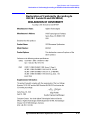
E6432A Microwave Synthesizer
Part Number: E6432-90027
Printed in USA
August 2000
Supersedes: July 1999
© Copyright 1999-2000 Agilent Technologies
Notice
The information contained in this document is subject to change without notice.
Agilent Technologies makes no warranty of any kind with regard to this material,
including, but not limited to, the implied warranties of merchantability and fitness for a
particular purpose. Agilent Technologies shall not be liable for errors contained herein or
for incidental or consequential damages in connection with the furnishing, performance, or
use of this material.
Agilent Technologies assumes no responsibility for the use or reliability of its software on
equipment that is not furnished by Agilent Technologies.
This document contains proprietary information which is protected by copyright. All rights
are reserved. No part of this document may be photocopied, reproduced, or translated to
another language without prior written consent of Agilent Technologies.
Restricted Rights Legend
Use, duplication, or disclosure by the U.S. Government is subject to restrictions as set forth
in subparagraph (c)(1)(ii) of the Rights in Technical Data and Computer Software clause at
DFARS 252.227-7013 for DOD agencies, and subparagraphs (c)(1) and (c)(2) of the
Commercial Computer Software Restricted Rights clause at FAR 52.227-19 for other
agencies.
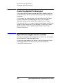
Trademarks and Product Names Acknowledgments
The following list of trademarks and product names are referenced in this user’s guide:
• Adobe® Acrobat® is a trademark of Adobe Systems Incorporated.
• LabVIEW is a product of National Instruments Corporation.
• LabWindows is a product of National Instruments Corporation.
• QuickTime™ is a U.S. trademark of Apple Computer, Inc.
• Windows NT® is a U.S. registered trademark of Microsoft Corporation.
• Notepad and WordPad are products of Microsoft Corporation.
ii
Agilent E6432A Microwave Synthesizer User’s Guide
Warranty
This Agilent Technologies instrument product is warranted against defects in material and
workmanship for a period of one year from date of shipment. During the warranty period,
Agilent Technologies will, at its option, either repair or replace products which prove to be
defective.
For warranty service or repair, this product must be returned to a service facility
designated by Agilent Technologies. Buyer shall prepay shipping charges to Agilent
Technologies and Agilent Technologies shall pay shipping charges to return the product to
Buyer. However, Buyer shall pay all shipping charges, duties, and taxes for products
returned to Agilent Technologies from another country.
Agilent Technologies warrants that its software and firmware designated by Agilent
Technologies for use with an instrument will execute its programming instructions when
properly installed on that instrument. Agilent Technologies does not warrant that the
operation of the instrument, or software, or firmware will be uninterrupted or error-free.
Limitation of Warranty
The foregoing warranty shall not apply to defects resulting from improper or inadequate
maintenance by Buyer, Buyer-supplied software or interfacing, unauthorized modification
or misuse, operation outside of the environmental specifications for the product, or
improper site preparation or maintenance.
NO OTHER WARRANTY IS EXPRESSED OR IMPLIED. AGILENT TECHNOLOGIES
SPECIFICALLY DISCLAIMS THE IMPLIED WARRANTIES OF MERCHANTABILITY
AND FITNESS FOR A PARTICULAR PURPOSE.
Exclusive Remedies
THE REMEDIES PROVIDED HEREIN ARE BUYER’S SOLE AND EXCLUSIVE
REMEDIES. AGILENT TECHNOLOGIES SHALL NOT BE LIABLE FOR ANY DIRECT,
INDIRECT, SPECIAL, INCIDENTAL, OR CONSEQUENTIAL DAMAGES, WHETHER
BASED ON CONTRACT, TORT, OR ANY OTHER LEGAL THEORY.
Agilent E6432A Microwave Synthesizer User’s Guide
iii
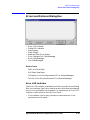
In This Book...
In this user guide you will learn about:
• Installation
• Hardware Front Panel Connectors and LEDs
• Soft Front Panel Controls and its Various Pull Down Menus and Dialog Boxes
• Remote Programming with VXIplug&play Functions in C, VEE, or LabVIEW
• Applications and Example Programs
• Specifications and Characteristics
• Getting Additional Help from Agilent Technologies
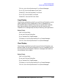
This user guide prepares you for your first steps in using the Agilent Technologies E6432A
microwave synthesizer in a VXI system. The standard Agilent Technologies E6432A
microwave synthesizer is a C-size, VXI, modular microwave source optimized for system
use that occupies three slots in a VXI mainframe. The arbitrary waveform generators
(ARBs) for generating AM, FM, and Pulse drive signals are external to the synthesizer and
take additional VXI slots.
Fast Response to VXI Host Interface
The synthesizer is based on a drift canceling circuit employing a fast tuning microwave
VCO. In addition, the synthesizer’s assist processor is optimized for fast data throughput
and the phase-locked loops are optimized for fast settling. The resulting frequency
switching times are in the hundreds of microseconds. Settling time for an amplitude
change is similar.
Register Based
To keep the synthesizer's response fast, it is register based with a minimum of "smarts."
This gives the user the maximum amount of flexibility in how the synthesizer is used.
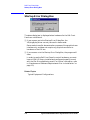
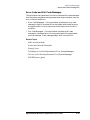
How to proceed…
First, refer to installation to learn about the hardware and software requirements for
using this product. After installing the Agilent Technologies E6432A VXIplug&play driver
software, become familiar with the features available on the hardware front panel
connectors and LEDs. When ready, become familiar with the soft front panel and its
various pull down sub-windows and dialog boxes. Finally, learn how to program with
VXIplug&play functions using C, Agilent Technologies VEE, or National Instruments
LabVIEW.
iv
Agilent E6432A Microwave Synthesizer User’s Guide
Contents
1. Installation
Overview . . . . . . . . . . . . . . . . . . . . . . . . . . . . . . . . . . . . . . . . . . . . . . . . . . . . . . . . . . . . . . . . . . .1-2
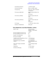
Hardware and Software Requirements
Prior to Installation . . . . . . . . . . . . . . . . . . . . . . . . . . . . . . . . . . . . . . . . . . . . . . . . . . . . . . . . . .1-3
Year 2000 (Y2K) Compliancy . . . . . . . . . . . . . . . . . . . . . . . . . . . . . . . . . . . . . . . . . . . . . . . . .1-3
Prior to Installation of the E6432A . . . . . . . . . . . . . . . . . . . . . . . . . . . . . . . . . . . . . . . . . . . .1-4
(Option 1) Install the Agilent Technologies I/O Library (which
contains Agilent Technologies VISA 1.1) . . . . . . . . . . . . . . . . . . . . . . . . . . . . . . . . . . . . . . . . .1-7
(Option 2) Run the Pre-Installed Agilent Technologies I/O Library
(which contains Agilent Technologies VISA 1.1) . . . . . . . . . . . . . . . . . . . . . . . . . . . . . . . . . . .1-8
(Option 3) Install the National Instruments VISA Library. . . . . . . . . . . . . . . . . . . . . . . . . .1-10
Installation of the E6432A Microwave Synthesizer . . . . . . . . . . . . . . . . . . . . . . . . . . . . . . . .1-11
Folders and Files Supplied with the E6432A VXIplug&play Driver . . . . . . . . . . . . . . . . . .1-13
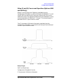
To Generate a New HPE6432.dll File . . . . . . . . . . . . . . . . . . . . . . . . . . . . . . . . . . . . . . . . . . .1-18
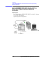
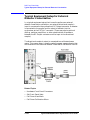
Typical Equipment Configurations . . . . . . . . . . . . . . . . . . . . . . . . . . . . . . . . . . . . . . . . . . . . .1-19
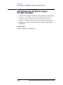
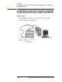
Agilent E8491B IEEE-1394 - Used with Three E1445A Arbitrary
Waveform Synthesizers . . . . . . . . . . . . . . . . . . . . . . . . . . . . . . . . . . . . . . . . . . . . . . . . . . . . . .1-20
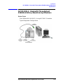
Agilent E8491B IEEE-1394 - Used with Three Racal 3152 Arbitrary
Waveform Generators . . . . . . . . . . . . . . . . . . . . . . . . . . . . . . . . . . . . . . . . . . . . . . . . . . . . . . .1-21
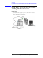
Agilent E8491B IEEE-1394 - Used with One Racal 3153 Triple
Arbitrary Waveform Generator . . . . . . . . . . . . . . . . . . . . . . . . . . . . . . . . . . . . . . . . . . . . . . . .1-22
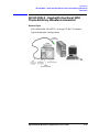
Agilent E8491B IEEE-1394 - Used with Three-Pair of E6432A and
Racal 3153 to Produce Radar Simulations . . . . . . . . . . . . . . . . . . . . . . . . . . . . . . . . . . . . . . .1-23
Slot 0 Module (NI VXI-MXI-2)- Using a PCI-MXI-2 Interface . . . . . . . . . . . . . . . . . . . . . . .1-24
NI VXI-MXI-2 - Used with Three Agilent E1445A Arbitrary Waveform Synthesizers . . . .1-25
NI VXI-MXI-2 - Used with Three Racal 3152 Arbitrary Waveform Generators. . . . . . . . . .1-26
NI VXI-MXI-2 - Used with One Racal 3153 Triple Arbitrary Waveform Generator . . . . . .1-27
NI VXI-MXI-2 - Used with Three-Pair of E6432A and Racal 3153 to
Produce Radar Simulations . . . . . . . . . . . . . . . . . . . . . . . . . . . . . . . . . . . . . . . . . . . . . . . . . . .1-28
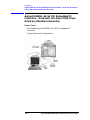
Slot 0 Module (Agilent E6233A, 4A, 5A VXI Embedded PC Controller). . . . . . . . . . . . . . . .1-29
Agilent E6233A, 4A, 5A VXI Embedded PC Controller - Used with
Three Agilent E1445A Arbitrary Waveform Synthesizers. . . . . . . . . . . . . . . . . . . . . . . . . . .1-30
Agilent E6233A, 4A, 5A VXI Embedded PC Controller - Used with
Three Racal 3152 Arbitrary Waveform Generators . . . . . . . . . . . . . . . . . . . . . . . . . . . . . . . .1-31
Agilent E6233A, 4A, 5A VXI Embedded PC Controller - Used with
One Racal 3153 Triple Arbitrary Waveform Generator . . . . . . . . . . . . . . . . . . . . . . . . . . . . .1-32
Agilent E6432A Acceptance Test Procedure . . . . . . . . . . . . . . . . . . . . . . . . . . . . . . . . . . . . . .1-33
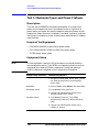
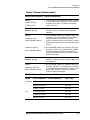
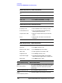
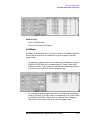
Test 1. Maximum Power and Power Flatness . . . . . . . . . . . . . . . . . . . . . . . . . . . . . . . . . . . .1-34
Description . . . . . . . . . . . . . . . . . . . . . . . . . . . . . . . . . . . . . . . . . . . . . . . . . . . . . . . . . . . . . .1-34
Required Test Equipment . . . . . . . . . . . . . . . . . . . . . . . . . . . . . . . . . . . . . . . . . . . . . . . . . . .1-34
Equipment Setup . . . . . . . . . . . . . . . . . . . . . . . . . . . . . . . . . . . . . . . . . . . . . . . . . . . . . . . . .1-34
Maximum Power Measurement . . . . . . . . . . . . . . . . . . . . . . . . . . . . . . . . . . . . . . . . . . . . . .1-36
Power Flatness Measurement . . . . . . . . . . . . . . . . . . . . . . . . . . . . . . . . . . . . . . . . . . . . . . .1-37
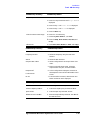
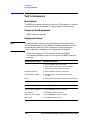
Test 2. AM Accuracy. . . . . . . . . . . . . . . . . . . . . . . . . . . . . . . . . . . . . . . . . . . . . . . . . . . . . . . . .1-38
Description . . . . . . . . . . . . . . . . . . . . . . . . . . . . . . . . . . . . . . . . . . . . . . . . . . . . . . . . . . . . . .1-38
Required Test Equipment . . . . . . . . . . . . . . . . . . . . . . . . . . . . . . . . . . . . . . . . . . . . . . . . . . .1-38
Equipment Setup . . . . . . . . . . . . . . . . . . . . . . . . . . . . . . . . . . . . . . . . . . . . . . . . . . . . . . . . .1-38
AM Accuracy Measurement . . . . . . . . . . . . . . . . . . . . . . . . . . . . . . . . . . . . . . . . . . . . . . . . .1-40
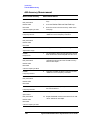
Test 3. FM Accuracy . . . . . . . . . . . . . . . . . . . . . . . . . . . . . . . . . . . . . . . . . . . . . . . . . . . . . . . . .1-43
Contents-1
Contents
Description . . . . . . . . . . . . . . . . . . . . . . . . . . . . . . . . . . . . . . . . . . . . . . . . . . . . . . . . . . . . . . 1-43
Equipment Required: . . . . . . . . . . . . . . . . . . . . . . . . . . . . . . . . . . . . . . . . . . . . . . . . . . . . . . 1-43
Equipment Setup:. . . . . . . . . . . . . . . . . . . . . . . . . . . . . . . . . . . . . . . . . . . . . . . . . . . . . . . . . 1-43
Test 4. Pulse Modulation Level Accuracy. . . . . . . . . . . . . . . . . . . . . . . . . . . . . . . . . . . . . . . . 1-47
Description . . . . . . . . . . . . . . . . . . . . . . . . . . . . . . . . . . . . . . . . . . . . . . . . . . . . . . . . . . . . . . 1-47
Required Test Equipment . . . . . . . . . . . . . . . . . . . . . . . . . . . . . . . . . . . . . . . . . . . . . . . . . . 1-47
Equipment Setup . . . . . . . . . . . . . . . . . . . . . . . . . . . . . . . . . . . . . . . . . . . . . . . . . . . . . . . . . 1-47
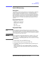
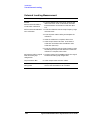
Test 5. Harmonics . . . . . . . . . . . . . . . . . . . . . . . . . . . . . . . . . . . . . . . . . . . . . . . . . . . . . . . . . . 1-50
Description . . . . . . . . . . . . . . . . . . . . . . . . . . . . . . . . . . . . . . . . . . . . . . . . . . . . . . . . . . . . . . 1-50
Required Test Equipment . . . . . . . . . . . . . . . . . . . . . . . . . . . . . . . . . . . . . . . . . . . . . . . . . . 1-50
Equipment Setup . . . . . . . . . . . . . . . . . . . . . . . . . . . . . . . . . . . . . . . . . . . . . . . . . . . . . . . . . 1-50
Harmonics Measurement. . . . . . . . . . . . . . . . . . . . . . . . . . . . . . . . . . . . . . . . . . . . . . . . . . . 1-51
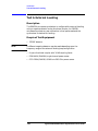
Test 6. External Leveling . . . . . . . . . . . . . . . . . . . . . . . . . . . . . . . . . . . . . . . . . . . . . . . . . . . . 1-52
Description . . . . . . . . . . . . . . . . . . . . . . . . . . . . . . . . . . . . . . . . . . . . . . . . . . . . . . . . . . . . . . 1-52
Required Test Equipment . . . . . . . . . . . . . . . . . . . . . . . . . . . . . . . . . . . . . . . . . . . . . . . . . . 1-52
Equipment Setup . . . . . . . . . . . . . . . . . . . . . . . . . . . . . . . . . . . . . . . . . . . . . . . . . . . . . . . . . 1-53
External Leveling Measurement. . . . . . . . . . . . . . . . . . . . . . . . . . . . . . . . . . . . . . . . . . . . . 1-54
Test 7. I/Q Functionality . . . . . . . . . . . . . . . . . . . . . . . . . . . . . . . . . . . . . . . . . . . . . . . . . . . . 1-55
Description:. . . . . . . . . . . . . . . . . . . . . . . . . . . . . . . . . . . . . . . . . . . . . . . . . . . . . . . . . . . . . . 1-55
Equipment Required: . . . . . . . . . . . . . . . . . . . . . . . . . . . . . . . . . . . . . . . . . . . . . . . . . . . . . . 1-55
Equipment Setup:. . . . . . . . . . . . . . . . . . . . . . . . . . . . . . . . . . . . . . . . . . . . . . . . . . . . . . . . . 1-55
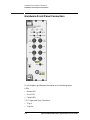
2. Hardware Front Panel Connectors
Hardware Front Panel Connectors. . . . . . . . . . . . . . . . . . . . . . . . . . . . . . . . . . . . . . . . . . . . . . 2-2
Access LED . . . . . . . . . . . . . . . . . . . . . . . . . . . . . . . . . . . . . . . . . . . . . . . . . . . . . . . . . . . . . . . 2-4
Error LED . . . . . . . . . . . . . . . . . . . . . . . . . . . . . . . . . . . . . . . . . . . . . . . . . . . . . . . . . . . . . . . . 2-4
Failed LED . . . . . . . . . . . . . . . . . . . . . . . . . . . . . . . . . . . . . . . . . . . . . . . . . . . . . . . . . . . . . . . 2-5
TTL Trig In . . . . . . . . . . . . . . . . . . . . . . . . . . . . . . . . . . . . . . . . . . . . . . . . . . . . . . . . . . . . . . . 2-6
TTL Trig Out . . . . . . . . . . . . . . . . . . . . . . . . . . . . . . . . . . . . . . . . . . . . . . . . . . . . . . . . . . . . . 2-6
TTL Sync Out . . . . . . . . . . . . . . . . . . . . . . . . . . . . . . . . . . . . . . . . . . . . . . . . . . . . . . . . . . . . . 2-6
10 MHz In . . . . . . . . . . . . . . . . . . . . . . . . . . . . . . . . . . . . . . . . . . . . . . . . . . . . . . . . . . . . . . . . 2-6
10 MHz Out . . . . . . . . . . . . . . . . . . . . . . . . . . . . . . . . . . . . . . . . . . . . . . . . . . . . . . . . . . . . . . 2-7
TTL Sync In . . . . . . . . . . . . . . . . . . . . . . . . . . . . . . . . . . . . . . . . . . . . . . . . . . . . . . . . . . . . . . 2-7
AM Input. . . . . . . . . . . . . . . . . . . . . . . . . . . . . . . . . . . . . . . . . . . . . . . . . . . . . . . . . . . . . . . . . 2-8
FM Input. . . . . . . . . . . . . . . . . . . . . . . . . . . . . . . . . . . . . . . . . . . . . . . . . . . . . . . . . . . . . . . . 2-11
PULSE Input . . . . . . . . . . . . . . . . . . . . . . . . . . . . . . . . . . . . . . . . . . . . . . . . . . . . . . . . . . . . 2-13
Ext ALC Input . . . . . . . . . . . . . . . . . . . . . . . . . . . . . . . . . . . . . . . . . . . . . . . . . . . . . . . . . . . 2-14
I/Q Inputs . . . . . . . . . . . . . . . . . . . . . . . . . . . . . . . . . . . . . . . . . . . . . . . . . . . . . . . . . . . . . . . 2-15
300 MHz IF In . . . . . . . . . . . . . . . . . . . . . . . . . . . . . . . . . . . . . . . . . . . . . . . . . . . . . . . . . . . 2-15
1200 MHz Reference Out . . . . . . . . . . . . . . . . . . . . . . . . . . . . . . . . . . . . . . . . . . . . . . . . . . . 2-16
RF Output. . . . . . . . . . . . . . . . . . . . . . . . . . . . . . . . . . . . . . . . . . . . . . . . . . . . . . . . . . . . . . . 2-16
3. Soft Front Panel Help
Startup Error Dialog Box . . . . . . . . . . . . . . . . . . . . . . . . . . . . . . . . . . . . . . . . . . . . . . . . . . . . . 3-4
Unlocked Error Indicator . . . . . . . . . . . . . . . . . . . . . . . . . . . . . . . . . . . . . . . . . . . . . . . . . . . . . 3-5
Unleveled Error Indicator . . . . . . . . . . . . . . . . . . . . . . . . . . . . . . . . . . . . . . . . . . . . . . . . . . . . . 3-6
Atten Lock Indicator . . . . . . . . . . . . . . . . . . . . . . . . . . . . . . . . . . . . . . . . . . . . . . . . . . . . . . . . . 3-7
Ext Ref Indicator . . . . . . . . . . . . . . . . . . . . . . . . . . . . . . . . . . . . . . . . . . . . . . . . . . . . . . . . . . . . 3-8
Contents-2
Contents
Error LED Indicator. . . . . . . . . . . . . . . . . . . . . . . . . . . . . . . . . . . . . . . . . . . . . . . . . . . . . . . . . .3-9
Failed LED Indicator . . . . . . . . . . . . . . . . . . . . . . . . . . . . . . . . . . . . . . . . . . . . . . . . . . . . . . . .3-10
RF Output Controls . . . . . . . . . . . . . . . . . . . . . . . . . . . . . . . . . . . . . . . . . . . . . . . . . . . . . . . . .3-11
Yellow Background Entry Boxes and Red Entry Values. . . . . . . . . . . . . . . . . . . . . . . . . . .3-11
Frequency Control . . . . . . . . . . . . . . . . . . . . . . . . . . . . . . . . . . . . . . . . . . . . . . . . . . . . . . . . . .3-13
Frequency Units . . . . . . . . . . . . . . . . . . . . . . . . . . . . . . . . . . . . . . . . . . . . . . . . . . . . . . . . . . . .3-14
Arrow Keys . . . . . . . . . . . . . . . . . . . . . . . . . . . . . . . . . . . . . . . . . . . . . . . . . . . . . . . . . . . . . . . .3-15
Output Power Control . . . . . . . . . . . . . . . . . . . . . . . . . . . . . . . . . . . . . . . . . . . . . . . . . . . . . . .3-16
Attenuation Control . . . . . . . . . . . . . . . . . . . . . . . . . . . . . . . . . . . . . . . . . . . . . . . . . . . . . . . . .3-18
ALC Power Control . . . . . . . . . . . . . . . . . . . . . . . . . . . . . . . . . . . . . . . . . . . . . . . . . . . . . . . . .3-19
RF ON/OFF Control . . . . . . . . . . . . . . . . . . . . . . . . . . . . . . . . . . . . . . . . . . . . . . . . . . . . . . . . .3-20
Reset Control . . . . . . . . . . . . . . . . . . . . . . . . . . . . . . . . . . . . . . . . . . . . . . . . . . . . . . . . . . . . . .3-21
Leveling (ALC) Controls . . . . . . . . . . . . . . . . . . . . . . . . . . . . . . . . . . . . . . . . . . . . . . . . . . . . .3-22
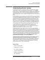
Understanding the ALC System . . . . . . . . . . . . . . . . . . . . . . . . . . . . . . . . . . . . . . . . . . . . . . .3-23
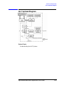
ALC System Diagram . . . . . . . . . . . . . . . . . . . . . . . . . . . . . . . . . . . . . . . . . . . . . . . . . . . . . . .3-25
Internal Leveling Point. . . . . . . . . . . . . . . . . . . . . . . . . . . . . . . . . . . . . . . . . . . . . . . . . . . . .3-26
External Leveling Point . . . . . . . . . . . . . . . . . . . . . . . . . . . . . . . . . . . . . . . . . . . . . . . . . . . .3-27
ALC On/Off . . . . . . . . . . . . . . . . . . . . . . . . . . . . . . . . . . . . . . . . . . . . . . . . . . . . . . . . . . . . . .3-28
Power Search. . . . . . . . . . . . . . . . . . . . . . . . . . . . . . . . . . . . . . . . . . . . . . . . . . . . . . . . . . . . .3-29
Coupled Operation . . . . . . . . . . . . . . . . . . . . . . . . . . . . . . . . . . . . . . . . . . . . . . . . . . . . . . . .3-30
Uncoupled Operation . . . . . . . . . . . . . . . . . . . . . . . . . . . . . . . . . . . . . . . . . . . . . . . . . . . . . .3-31
Modulation Controls. . . . . . . . . . . . . . . . . . . . . . . . . . . . . . . . . . . . . . . . . . . . . . . . . . . . . . . . .3-32
AM (On/Off) . . . . . . . . . . . . . . . . . . . . . . . . . . . . . . . . . . . . . . . . . . . . . . . . . . . . . . . . . . . . . .3-32
FM (On/Off) . . . . . . . . . . . . . . . . . . . . . . . . . . . . . . . . . . . . . . . . . . . . . . . . . . . . . . . . . . . . . .3-33
Pulse Modulation (On/Off) . . . . . . . . . . . . . . . . . . . . . . . . . . . . . . . . . . . . . . . . . . . . . . . . . .3-33
I/Q (On/Off) . . . . . . . . . . . . . . . . . . . . . . . . . . . . . . . . . . . . . . . . . . . . . . . . . . . . . . . . . . . . . .3-34
IF (On/Off) . . . . . . . . . . . . . . . . . . . . . . . . . . . . . . . . . . . . . . . . . . . . . . . . . . . . . . . . . . . . . . .3-34
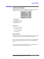
Pull Down File Menu . . . . . . . . . . . . . . . . . . . . . . . . . . . . . . . . . . . . . . . . . . . . . . . . . . . . . . . .3-35
New List. . . . . . . . . . . . . . . . . . . . . . . . . . . . . . . . . . . . . . . . . . . . . . . . . . . . . . . . . . . . . . . . .3-35
Exit. . . . . . . . . . . . . . . . . . . . . . . . . . . . . . . . . . . . . . . . . . . . . . . . . . . . . . . . . . . . . . . . . . . . .3-36
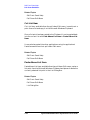
Pull Down Edit Menu. . . . . . . . . . . . . . . . . . . . . . . . . . . . . . . . . . . . . . . . . . . . . . . . . . . . . . . .3-37
Copy List Item. . . . . . . . . . . . . . . . . . . . . . . . . . . . . . . . . . . . . . . . . . . . . . . . . . . . . . . . . . . .3-37
Cut List Item . . . . . . . . . . . . . . . . . . . . . . . . . . . . . . . . . . . . . . . . . . . . . . . . . . . . . . . . . . . . .3-38
Paste Above List Item. . . . . . . . . . . . . . . . . . . . . . . . . . . . . . . . . . . . . . . . . . . . . . . . . . . . . .3-38
Paste Below List Item. . . . . . . . . . . . . . . . . . . . . . . . . . . . . . . . . . . . . . . . . . . . . . . . . . . . . .3-39
Delete List Item . . . . . . . . . . . . . . . . . . . . . . . . . . . . . . . . . . . . . . . . . . . . . . . . . . . . . . . . . .3-39
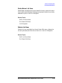
Pull Down View Menu . . . . . . . . . . . . . . . . . . . . . . . . . . . . . . . . . . . . . . . . . . . . . . . . . . . . . . .3-40
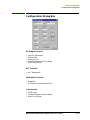
Configuration Dialog Box. . . . . . . . . . . . . . . . . . . . . . . . . . . . . . . . . . . . . . . . . . . . . . . . . . . . .3-41
Lock RF Attenuator . . . . . . . . . . . . . . . . . . . . . . . . . . . . . . . . . . . . . . . . . . . . . . . . . . . . . . .3-43
10 MHz Ref . . . . . . . . . . . . . . . . . . . . . . . . . . . . . . . . . . . . . . . . . . . . . . . . . . . . . . . . . . . . . .3-43
Settling Time . . . . . . . . . . . . . . . . . . . . . . . . . . . . . . . . . . . . . . . . . . . . . . . . . . . . . . . . . . . . .3-43
ALC Bandwidth. . . . . . . . . . . . . . . . . . . . . . . . . . . . . . . . . . . . . . . . . . . . . . . . . . . . . . . . . . .3-46
Deep AM . . . . . . . . . . . . . . . . . . . . . . . . . . . . . . . . . . . . . . . . . . . . . . . . . . . . . . . . . . . . . . . .3-47
AM Mode (Linear/Exponential) . . . . . . . . . . . . . . . . . . . . . . . . . . . . . . . . . . . . . . . . . . . . . .3-47
Dwell Time. . . . . . . . . . . . . . . . . . . . . . . . . . . . . . . . . . . . . . . . . . . . . . . . . . . . . . . . . . . . . . .3-48
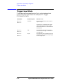
Trigger Input . . . . . . . . . . . . . . . . . . . . . . . . . . . . . . . . . . . . . . . . . . . . . . . . . . . . . . . . . . . . .3-49
Trigger Out (Front Panel). . . . . . . . . . . . . . . . . . . . . . . . . . . . . . . . . . . . . . . . . . . . . . . . . . .3-50
Trigger Out (VXI Backplane) . . . . . . . . . . . . . . . . . . . . . . . . . . . . . . . . . . . . . . . . . . . . . . . .3-51
Sync Input . . . . . . . . . . . . . . . . . . . . . . . . . . . . . . . . . . . . . . . . . . . . . . . . . . . . . . . . . . . . . . .3-52
Contents-3
Contents
Sync Out (Front Panel) . . . . . . . . . . . . . . . . . . . . . . . . . . . . . . . . . . . . . . . . . . . . . . . . . . . . 3-53
Sync Out (VXI Backplane) . . . . . . . . . . . . . . . . . . . . . . . . . . . . . . . . . . . . . . . . . . . . . . . . . . 3-54
FM Sensitivity (Option 002 Only) . . . . . . . . . . . . . . . . . . . . . . . . . . . . . . . . . . . . . . . . . . . . 3-56
Allow IF and I/Q Concurrent Operation (Options UNG and 300 Only) . . . . . . . . . . . . . . 3-57
IF Upconverter Calibration Attenuator (Option 300 and Option UNG Only) . . . . . . . . . 3-58
IF Sideband (Option 002, 300 or UNG). . . . . . . . . . . . . . . . . . . . . . . . . . . . . . . . . . . . . . . . 3-59
List Dialog Box . . . . . . . . . . . . . . . . . . . . . . . . . . . . . . . . . . . . . . . . . . . . . . . . . . . . . . . . . . . . 3-60
Start - List Playing Control . . . . . . . . . . . . . . . . . . . . . . . . . . . . . . . . . . . . . . . . . . . . . . . . . 3-61
Stop - List Playing Control . . . . . . . . . . . . . . . . . . . . . . . . . . . . . . . . . . . . . . . . . . . . . . . . . 3-61
Trigger - List Playing Control . . . . . . . . . . . . . . . . . . . . . . . . . . . . . . . . . . . . . . . . . . . . . . . 3-61
Sync - List Playing Control . . . . . . . . . . . . . . . . . . . . . . . . . . . . . . . . . . . . . . . . . . . . . . . . . 3-62
Repeat - List Playing Control . . . . . . . . . . . . . . . . . . . . . . . . . . . . . . . . . . . . . . . . . . . . . . . 3-62
Trig In (0, 1, 2) - List Playing Control . . . . . . . . . . . . . . . . . . . . . . . . . . . . . . . . . . . . . . . . . 3-63
Sync In (0, 1, 2, 3) - List Playing Control . . . . . . . . . . . . . . . . . . . . . . . . . . . . . . . . . . . . . . 3-64
Add Above - List Editing Control . . . . . . . . . . . . . . . . . . . . . . . . . . . . . . . . . . . . . . . . . . . . 3-65
Add Below - List Editing Control . . . . . . . . . . . . . . . . . . . . . . . . . . . . . . . . . . . . . . . . . . . . 3-66
Del - List Editing Control . . . . . . . . . . . . . . . . . . . . . . . . . . . . . . . . . . . . . . . . . . . . . . . . . . 3-67
Step - of a List Point. . . . . . . . . . . . . . . . . . . . . . . . . . . . . . . . . . . . . . . . . . . . . . . . . . . . . . . 3-67
Frequency - of a List Point. . . . . . . . . . . . . . . . . . . . . . . . . . . . . . . . . . . . . . . . . . . . . . . . . . 3-67
ALC Power of a List Point . . . . . . . . . . . . . . . . . . . . . . . . . . . . . . . . . . . . . . . . . . . . . . . . . . 3-68
Attenuation of a List Point . . . . . . . . . . . . . . . . . . . . . . . . . . . . . . . . . . . . . . . . . . . . . . . . . 3-69
Flags - of a List Point . . . . . . . . . . . . . . . . . . . . . . . . . . . . . . . . . . . . . . . . . . . . . . . . . . . . . . 3-69
Sync Out - of a List Point. . . . . . . . . . . . . . . . . . . . . . . . . . . . . . . . . . . . . . . . . . . . . . . . . . . 3-70
Blanking - of a List Point. . . . . . . . . . . . . . . . . . . . . . . . . . . . . . . . . . . . . . . . . . . . . . . . . . . 3-70
Long Blanking - of a List Point . . . . . . . . . . . . . . . . . . . . . . . . . . . . . . . . . . . . . . . . . . . . . . 3-72
Power Search - of a List Point . . . . . . . . . . . . . . . . . . . . . . . . . . . . . . . . . . . . . . . . . . . . . . . 3-74
List Point Calculator Dialog Box . . . . . . . . . . . . . . . . . . . . . . . . . . . . . . . . . . . . . . . . . . . . . . 3-76
Frequency Start . . . . . . . . . . . . . . . . . . . . . . . . . . . . . . . . . . . . . . . . . . . . . . . . . . . . . . . . . . 3-78
Frequency Stop. . . . . . . . . . . . . . . . . . . . . . . . . . . . . . . . . . . . . . . . . . . . . . . . . . . . . . . . . . . 3-78
Frequency Step. . . . . . . . . . . . . . . . . . . . . . . . . . . . . . . . . . . . . . . . . . . . . . . . . . . . . . . . . . . 3-78
ALC Power Start . . . . . . . . . . . . . . . . . . . . . . . . . . . . . . . . . . . . . . . . . . . . . . . . . . . . . . . . . 3-79
ALC Power Stop . . . . . . . . . . . . . . . . . . . . . . . . . . . . . . . . . . . . . . . . . . . . . . . . . . . . . . . . . . 3-79
ALC Power Step . . . . . . . . . . . . . . . . . . . . . . . . . . . . . . . . . . . . . . . . . . . . . . . . . . . . . . . . . . 3-80
Placement Control . . . . . . . . . . . . . . . . . . . . . . . . . . . . . . . . . . . . . . . . . . . . . . . . . . . . . . . . 3-80
Don’t Specify the Start, Stop, Step, or the # of Steps Parameter . . . . . . . . . . . . . . . . . . . 3-81
Don’t Specify Step. . . . . . . . . . . . . . . . . . . . . . . . . . . . . . . . . . . . . . . . . . . . . . . . . . . . . . . . . 3-81
Don’t Specify Start . . . . . . . . . . . . . . . . . . . . . . . . . . . . . . . . . . . . . . . . . . . . . . . . . . . . . . . . 3-82
Don’t Specify Stop. . . . . . . . . . . . . . . . . . . . . . . . . . . . . . . . . . . . . . . . . . . . . . . . . . . . . . . . . 3-83
Don’t Specify # of Steps . . . . . . . . . . . . . . . . . . . . . . . . . . . . . . . . . . . . . . . . . . . . . . . . . . . . 3-83
# of Steps. . . . . . . . . . . . . . . . . . . . . . . . . . . . . . . . . . . . . . . . . . . . . . . . . . . . . . . . . . . . . . . . 3-87
Apply - List Point Calculator Values. . . . . . . . . . . . . . . . . . . . . . . . . . . . . . . . . . . . . . . . . . 3-88
Errors and Failures Dialog Box . . . . . . . . . . . . . . . . . . . . . . . . . . . . . . . . . . . . . . . . . . . . . . . 3-89
Error LED Indicator. . . . . . . . . . . . . . . . . . . . . . . . . . . . . . . . . . . . . . . . . . . . . . . . . . . . . . . 3-89
Failed LED Indicator . . . . . . . . . . . . . . . . . . . . . . . . . . . . . . . . . . . . . . . . . . . . . . . . . . . . . . 3-90
Copy Display. . . . . . . . . . . . . . . . . . . . . . . . . . . . . . . . . . . . . . . . . . . . . . . . . . . . . . . . . . . . . 3-91
Clear Display . . . . . . . . . . . . . . . . . . . . . . . . . . . . . . . . . . . . . . . . . . . . . . . . . . . . . . . . . . . . 3-91
Read and Clear Error Queue . . . . . . . . . . . . . . . . . . . . . . . . . . . . . . . . . . . . . . . . . . . . . . . . 3-92
Error-Code and Fail-Code Messages . . . . . . . . . . . . . . . . . . . . . . . . . . . . . . . . . . . . . . . . . . 3-93
Error-Code Messages . . . . . . . . . . . . . . . . . . . . . . . . . . . . . . . . . . . . . . . . . . . . . . . . . . . . . . 3-94
Contents-4
Contents
Fail-Code Messages. . . . . . . . . . . . . . . . . . . . . . . . . . . . . . . . . . . . . . . . . . . . . . . . . . . . . . .3-108
To Display a List of the Synthesizer’s Error Queue Messages . . . . . . . . . . . . . . . . . . . . . . 3-113
To Print a List of the Synthesizer’s Error Queue Messages . . . . . . . . . . . . . . . . . . . . . . . . 3-114
Pull Down Diagnostics Menu. . . . . . . . . . . . . . . . . . . . . . . . . . . . . . . . . . . . . . . . . . . . . . . . .3-115
Quick Self Test With No RF . . . . . . . . . . . . . . . . . . . . . . . . . . . . . . . . . . . . . . . . . . . . . . . . 3-115
Full Self Test With RF On . . . . . . . . . . . . . . . . . . . . . . . . . . . . . . . . . . . . . . . . . . . . . . . . . 3-116
View Last Quick Self Test. . . . . . . . . . . . . . . . . . . . . . . . . . . . . . . . . . . . . . . . . . . . . . . . . . 3-116
View Last Full Self Test . . . . . . . . . . . . . . . . . . . . . . . . . . . . . . . . . . . . . . . . . . . . . . . . . . . 3-117
Pull Down Calibration Menu . . . . . . . . . . . . . . . . . . . . . . . . . . . . . . . . . . . . . . . . . . . . . . . . .3-118
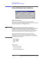
External Detector Linearization . . . . . . . . . . . . . . . . . . . . . . . . . . . . . . . . . . . . . . . . . . . . . . 3-119
Typical Equipment Setup for External Detector Linearization. . . . . . . . . . . . . . . . . . . . . .3-120
Start Frequency of an External Detector Linearization . . . . . . . . . . . . . . . . . . . . . . . . . .3-121
Stop Frequency of an External Detector Linearization . . . . . . . . . . . . . . . . . . . . . . . . . .3-121
Start an External Detector Linearization . . . . . . . . . . . . . . . . . . . . . . . . . . . . . . . . . . . . .3-122
Power Meter Reading Dialog Box . . . . . . . . . . . . . . . . . . . . . . . . . . . . . . . . . . . . . . . . . . .3-123
External Modulator Gain Calibration. . . . . . . . . . . . . . . . . . . . . . . . . . . . . . . . . . . . . . . . . .3-124
Start Frequency for External Modulator Gain Calibration . . . . . . . . . . . . . . . . . . . . . . .3-125
Stop Frequency for External Modulator Gain Calibration. . . . . . . . . . . . . . . . . . . . . . . .3-125
Step Frequency for External Modulator Gain Calibration. . . . . . . . . . . . . . . . . . . . . . . .3-126
Start an External Modulator Gain Calibration. . . . . . . . . . . . . . . . . . . . . . . . . . . . . . . . .3-127
Reset External Detector Calibration to Factory Default . . . . . . . . . . . . . . . . . . . . . . . . .3-129
I/Q Calibration (Option UNG Only) . . . . . . . . . . . . . . . . . . . . . . . . . . . . . . . . . . . . . . . . . . .3-130
Understanding I/Q Calibration . . . . . . . . . . . . . . . . . . . . . . . . . . . . . . . . . . . . . . . . . . . . .3-135
I/Q Calibration Dialog Box . . . . . . . . . . . . . . . . . . . . . . . . . . . . . . . . . . . . . . . . . . . . . . . . .3-138
I/Q External Source Adjustments Dialog Box . . . . . . . . . . . . . . . . . . . . . . . . . . . . . . . . . .3-142
IF Calibration (Option 300 Only) . . . . . . . . . . . . . . . . . . . . . . . . . . . . . . . . . . . . . . . . . . . . .3-146
4. Programming Information
Introduction to Programming . . . . . . . . . . . . . . . . . . . . . . . . . . . . . . . . . . . . . . . . . . . . . . . . . .4-2
Selecting Functions. . . . . . . . . . . . . . . . . . . . . . . . . . . . . . . . . . . . . . . . . . . . . . . . . . . . . . . . .4-2
Compiling and Linking Programs Using Integrated Environments . . . . . . . . . . . . . . . . . .4-2
Getting Started with Agilent VEE . . . . . . . . . . . . . . . . . . . . . . . . . . . . . . . . . . . . . . . . . . . . .4-3
Getting Started with LabVIEW . . . . . . . . . . . . . . . . . . . . . . . . . . . . . . . . . . . . . . . . . . . . . . .4-3
Getting Started with LabWindows. . . . . . . . . . . . . . . . . . . . . . . . . . . . . . . . . . . . . . . . . . . . .4-4
Using the VXIplug&play Driver . . . . . . . . . . . . . . . . . . . . . . . . . . . . . . . . . . . . . . . . . . . . . . . .4-5
Visual C++ Programing . . . . . . . . . . . . . . . . . . . . . . . . . . . . . . . . . . . . . . . . . . . . . . . . . . . . .4-6
Determining the Logical Address of the Synthesizer When Set to Be
Auto-Configured (FF) . . . . . . . . . . . . . . . . . . . . . . . . . . . . . . . . . . . . . . . . . . . . . . . . . . . . . . . . .4-8
Opening an Instrument Session. . . . . . . . . . . . . . . . . . . . . . . . . . . . . . . . . . . . . . . . . . . . . . .4-9
Closing an Instrument Session . . . . . . . . . . . . . . . . . . . . . . . . . . . . . . . . . . . . . . . . . . . . . .4-11
Agilent Technologies VISA Data Types . . . . . . . . . . . . . . . . . . . . . . . . . . . . . . . . . . . . . . . .4-11
Querying the Instrument . . . . . . . . . . . . . . . . . . . . . . . . . . . . . . . . . . . . . . . . . . . . . . . . . . .4-11
Events and Errors . . . . . . . . . . . . . . . . . . . . . . . . . . . . . . . . . . . . . . . . . . . . . . . . . . . . . . . . .4-12
VXIplug&play Commands (Function Prototypes) . . . . . . . . . . . . . . . . . . . . . . . . . . . . . . . . .4-13
VXIplug&play Commands (Functional List) . . . . . . . . . . . . . . . . . . . . . . . . . . . . . . . . . . . . .4-22
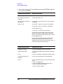
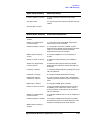
Alphabetical List of VXIplug&play Commands . . . . . . . . . . . . . . . . . . . . . . . . . . . . . . . . . . .4-34
HPE6432_ClearErrors . . . . . . . . . . . . . . . . . . . . . . . . . . . . . . . . . . . . . . . . . . . . . . . . . . . . .4-34
HPE6432_ClearList . . . . . . . . . . . . . . . . . . . . . . . . . . . . . . . . . . . . . . . . . . . . . . . . . . . . . . .4-35
HPE6432_close . . . . . . . . . . . . . . . . . . . . . . . . . . . . . . . . . . . . . . . . . . . . . . . . . . . . . . . . . . .4-36
Contents-5
Contents
HPE6432_EnterCalExtDetPowerMeterReading . . . . . . . . . . . . . . . . . . . . . . . . . . . . . . . . 4-37
HPE6432_EnterFlatnessCalReading . . . . . . . . . . . . . . . . . . . . . . . . . . . . . . . . . . . . . . . . . 4-40
HPE6432_error_message . . . . . . . . . . . . . . . . . . . . . . . . . . . . . . . . . . . . . . . . . . . . . . . . . . . 4-42
HPE6432_error_query . . . . . . . . . . . . . . . . . . . . . . . . . . . . . . . . . . . . . . . . . . . . . . . . . . . . . 4-43
HPE6432_GenerateAndLoadExtFreqTable . . . . . . . . . . . . . . . . . . . . . . . . . . . . . . . . . . . . 4-45
HPE6432_GenerateManualSyncInput . . . . . . . . . . . . . . . . . . . . . . . . . . . . . . . . . . . . . . . . 4-48
HPE6432_GenerateManualTriggerInput . . . . . . . . . . . . . . . . . . . . . . . . . . . . . . . . . . . . . . 4-49
HPE6432_GetAlcBandwidth . . . . . . . . . . . . . . . . . . . . . . . . . . . . . . . . . . . . . . . . . . . . . . . . 4-50
HPE6432_GetAmMode . . . . . . . . . . . . . . . . . . . . . . . . . . . . . . . . . . . . . . . . . . . . . . . . . . . . 4-51
HPE6432_GetAmpModState . . . . . . . . . . . . . . . . . . . . . . . . . . . . . . . . . . . . . . . . . . . . . . . . 4-52
HPE6432_GetAmplitudeBlankingTime . . . . . . . . . . . . . . . . . . . . . . . . . . . . . . . . . . . . . . . 4-53
HPE6432_GetAtten . . . . . . . . . . . . . . . . . . . . . . . . . . . . . . . . . . . . . . . . . . . . . . . . . . . . . . . 4-54
HPE6432_GetAttenAuto . . . . . . . . . . . . . . . . . . . . . . . . . . . . . . . . . . . . . . . . . . . . . . . . . . . 4-55
HPE6432_GetAttenuationLimits . . . . . . . . . . . . . . . . . . . . . . . . . . . . . . . . . . . . . . . . . . . . 4-56
HPE6432_GetBlankingState . . . . . . . . . . . . . . . . . . . . . . . . . . . . . . . . . . . . . . . . . . . . . . . . 4-57
HPE6432_GetDeepAmState . . . . . . . . . . . . . . . . . . . . . . . . . . . . . . . . . . . . . . . . . . . . . . . . 4-58
HPE6432_GetDwellTime . . . . . . . . . . . . . . . . . . . . . . . . . . . . . . . . . . . . . . . . . . . . . . . . . . . 4-59
HPE6432_GetErrorQueueCount . . . . . . . . . . . . . . . . . . . . . . . . . . . . . . . . . . . . . . . . . . . . . 4-60
HPE6432_GetExtIfInvert . . . . . . . . . . . . . . . . . . . . . . . . . . . . . . . . . . . . . . . . . . . . . . . . . . 4-61
HPE6432_GetExtIfState . . . . . . . . . . . . . . . . . . . . . . . . . . . . . . . . . . . . . . . . . . . . . . . . . . . 4-62
HPE6432_GetExtSyncOutput . . . . . . . . . . . . . . . . . . . . . . . . . . . . . . . . . . . . . . . . . . . . . . . 4-63
HPE6432_GetExtTriggerOutput . . . . . . . . . . . . . . . . . . . . . . . . . . . . . . . . . . . . . . . . . . . . . 4-64
HPE6432_GetFlatnessCalData . . . . . . . . . . . . . . . . . . . . . . . . . . . . . . . . . . . . . . . . . . . . . . 4-65
HPE6432_GetFreqAlcAtten. . . . . . . . . . . . . . . . . . . . . . . . . . . . . . . . . . . . . . . . . . . . . . . . . 4-67
HPE6432_GetFreqModExtSensitivity . . . . . . . . . . . . . . . . . . . . . . . . . . . . . . . . . . . . . . . . 4-68
HPE6432_GetFreqModState . . . . . . . . . . . . . . . . . . . . . . . . . . . . . . . . . . . . . . . . . . . . . . . . 4-69
HPE6432_GetFrequencyLimits. . . . . . . . . . . . . . . . . . . . . . . . . . . . . . . . . . . . . . . . . . . . . . 4-70
HPE6432_GetIAttenuation . . . . . . . . . . . . . . . . . . . . . . . . . . . . . . . . . . . . . . . . . . . . . . . . . 4-71
HPE6432_GetICal . . . . . . . . . . . . . . . . . . . . . . . . . . . . . . . . . . . . . . . . . . . . . . . . . . . . . . . . 4-72
HPE6432_GetIfAtten . . . . . . . . . . . . . . . . . . . . . . . . . . . . . . . . . . . . . . . . . . . . . . . . . . . . . . 4-73
HPE6432_GetIfLowerSidebandDac . . . . . . . . . . . . . . . . . . . . . . . . . . . . . . . . . . . . . . . . . . 4-74
HPE6432_GetIfUpperSidebandDac . . . . . . . . . . . . . . . . . . . . . . . . . . . . . . . . . . . . . . . . . . 4-75
HPE6432_GetIGainAdjust. . . . . . . . . . . . . . . . . . . . . . . . . . . . . . . . . . . . . . . . . . . . . . . . . . 4-76
HPE6432_GetIGainDac . . . . . . . . . . . . . . . . . . . . . . . . . . . . . . . . . . . . . . . . . . . . . . . . . . . . 4-77
HPE6432_GetInterruptFlags . . . . . . . . . . . . . . . . . . . . . . . . . . . . . . . . . . . . . . . . . . . . . . . 4-78
HPE6432_GetIOffsetAdjust. . . . . . . . . . . . . . . . . . . . . . . . . . . . . . . . . . . . . . . . . . . . . . . . . 4-79
HPE6432_GetIOffsetDac . . . . . . . . . . . . . . . . . . . . . . . . . . . . . . . . . . . . . . . . . . . . . . . . . . . 4-80
HPE6432_GetIqAdjustState . . . . . . . . . . . . . . . . . . . . . . . . . . . . . . . . . . . . . . . . . . . . . . . . 4-81
HPE6432_GetIqInput . . . . . . . . . . . . . . . . . . . . . . . . . . . . . . . . . . . . . . . . . . . . . . . . . . . . . 4-82
HPE6432_GetIqModState . . . . . . . . . . . . . . . . . . . . . . . . . . . . . . . . . . . . . . . . . . . . . . . . . . 4-83
HPE6432_GetLastSelfTestResults . . . . . . . . . . . . . . . . . . . . . . . . . . . . . . . . . . . . . . . . . . . 4-84
HPE6432_GetLevelingPoint . . . . . . . . . . . . . . . . . . . . . . . . . . . . . . . . . . . . . . . . . . . . . . . . 4-86
HPE6432_GetLevelingState . . . . . . . . . . . . . . . . . . . . . . . . . . . . . . . . . . . . . . . . . . . . . . . . 4-87
HPE6432_GetListIndex . . . . . . . . . . . . . . . . . . . . . . . . . . . . . . . . . . . . . . . . . . . . . . . . . . . . 4-88
HPE6432_GetLongBlankingState. . . . . . . . . . . . . . . . . . . . . . . . . . . . . . . . . . . . . . . . . . . . 4-90
HPE6432_GetLongBlankingTime . . . . . . . . . . . . . . . . . . . . . . . . . . . . . . . . . . . . . . . . . . . . 4-91
HPE6432_GetNormalBlankingTime. . . . . . . . . . . . . . . . . . . . . . . . . . . . . . . . . . . . . . . . . . 4-92
HPE6432_GetNumExtDetCalPoints. . . . . . . . . . . . . . . . . . . . . . . . . . . . . . . . . . . . . . . . . . 4-93
HPE6432_GetNumFlatnessCalPoints . . . . . . . . . . . . . . . . . . . . . . . . . . . . . . . . . . . . . . . . 4-96
Contents-6
Contents
HPE6432_GetOptionString . . . . . . . . . . . . . . . . . . . . . . . . . . . . . . . . . . . . . . . . . . . . . . . . .4-99
HPE6432_GetOutputPower . . . . . . . . . . . . . . . . . . . . . . . . . . . . . . . . . . . . . . . . . . . . . . . .4-100
HPE6432_GetPowerLimits. . . . . . . . . . . . . . . . . . . . . . . . . . . . . . . . . . . . . . . . . . . . . . . . .4-101
HPE6432_GetPowerLimitsAtFrequency . . . . . . . . . . . . . . . . . . . . . . . . . . . . . . . . . . . . . .4-102
HPE6432_GetPulseModState. . . . . . . . . . . . . . . . . . . . . . . . . . . . . . . . . . . . . . . . . . . . . . .4-103
HPE6432_GetQAttenuation . . . . . . . . . . . . . . . . . . . . . . . . . . . . . . . . . . . . . . . . . . . . . . . .4-104
HPE6432_GetQCal . . . . . . . . . . . . . . . . . . . . . . . . . . . . . . . . . . . . . . . . . . . . . . . . . . . . . . .4-105
HPE6432_GetQGainAdjust . . . . . . . . . . . . . . . . . . . . . . . . . . . . . . . . . . . . . . . . . . . . . . . .4-106
HPE6432_GetQGainDac. . . . . . . . . . . . . . . . . . . . . . . . . . . . . . . . . . . . . . . . . . . . . . . . . . .4-107
HPE6432_GetQOffsetAdjust . . . . . . . . . . . . . . . . . . . . . . . . . . . . . . . . . . . . . . . . . . . . . . .4-107
HPE6432_GetQOffsetDac. . . . . . . . . . . . . . . . . . . . . . . . . . . . . . . . . . . . . . . . . . . . . . . . . .4-109
HPE6432_GetQuadratureAdjust . . . . . . . . . . . . . . . . . . . . . . . . . . . . . . . . . . . . . . . . . . . . 4-110
HPE6432_GetQuadratureDac . . . . . . . . . . . . . . . . . . . . . . . . . . . . . . . . . . . . . . . . . . . . . . 4-111
HPE6432_GetRefSource . . . . . . . . . . . . . . . . . . . . . . . . . . . . . . . . . . . . . . . . . . . . . . . . . . . 4-112
HPE6432_GetRfOutputState . . . . . . . . . . . . . . . . . . . . . . . . . . . . . . . . . . . . . . . . . . . . . . . 4-113
HPE6432_GetSerialNumber . . . . . . . . . . . . . . . . . . . . . . . . . . . . . . . . . . . . . . . . . . . . . . . 4-114
HPE6432_GetSettlingTime . . . . . . . . . . . . . . . . . . . . . . . . . . . . . . . . . . . . . . . . . . . . . . . . 4-115
HPE6432_GetSyncInput. . . . . . . . . . . . . . . . . . . . . . . . . . . . . . . . . . . . . . . . . . . . . . . . . . . 4-116
HPE6432_GetSyncOutState. . . . . . . . . . . . . . . . . . . . . . . . . . . . . . . . . . . . . . . . . . . . . . . . 4-117
HPE6432_GetTriggerInput . . . . . . . . . . . . . . . . . . . . . . . . . . . . . . . . . . . . . . . . . . . . . . . . 4-118
HPE6432_GetUserBlankingState . . . . . . . . . . . . . . . . . . . . . . . . . . . . . . . . . . . . . . . . . . . 4-119
HPE6432_GetVbloDac . . . . . . . . . . . . . . . . . . . . . . . . . . . . . . . . . . . . . . . . . . . . . . . . . . . .4-120
HPE6432_GetVxiSyncOutput . . . . . . . . . . . . . . . . . . . . . . . . . . . . . . . . . . . . . . . . . . . . . .4-121
HPE6432_GetVxiTriggerOutput . . . . . . . . . . . . . . . . . . . . . . . . . . . . . . . . . . . . . . . . . . . .4-122
HPE6432_IfUpconverterLevelCalibrate . . . . . . . . . . . . . . . . . . . . . . . . . . . . . . . . . . . . . .4-123
HPE6432_IfUpconverterRestoreFactoryCal . . . . . . . . . . . . . . . . . . . . . . . . . . . . . . . . . . .4-124
HPE6432_init . . . . . . . . . . . . . . . . . . . . . . . . . . . . . . . . . . . . . . . . . . . . . . . . . . . . . . . . . . .4-125
HPE6432_IqCalibrate. . . . . . . . . . . . . . . . . . . . . . . . . . . . . . . . . . . . . . . . . . . . . . . . . . . . .4-128
HPE6432_IqRestoreFactoryCal . . . . . . . . . . . . . . . . . . . . . . . . . . . . . . . . . . . . . . . . . . . . .4-129
HPE6432_IqUpconverterLevelCalibrate . . . . . . . . . . . . . . . . . . . . . . . . . . . . . . . . . . . . . .4-130
HPE6432_IqUpconverterRestoreFactoryCal. . . . . . . . . . . . . . . . . . . . . . . . . . . . . . . . . . .4-132
HPE6432_IsListRunning . . . . . . . . . . . . . . . . . . . . . . . . . . . . . . . . . . . . . . . . . . . . . . . . . .4-133
HPE6432_PowerSearch . . . . . . . . . . . . . . . . . . . . . . . . . . . . . . . . . . . . . . . . . . . . . . . . . . .4-134
HPE6432_PutFlatnessCalData . . . . . . . . . . . . . . . . . . . . . . . . . . . . . . . . . . . . . . . . . . . . .4-136
HPE6432_ReadHwState. . . . . . . . . . . . . . . . . . . . . . . . . . . . . . . . . . . . . . . . . . . . . . . . . . .4-138
HPE6432_ReadInterruptHwState . . . . . . . . . . . . . . . . . . . . . . . . . . . . . . . . . . . . . . . . . . .4-139
HPE6432_ReadListData. . . . . . . . . . . . . . . . . . . . . . . . . . . . . . . . . . . . . . . . . . . . . . . . . . .4-140
HPE6432_readStatusByte_Q . . . . . . . . . . . . . . . . . . . . . . . . . . . . . . . . . . . . . . . . . . . . . . .4-143
HPE6432_reset . . . . . . . . . . . . . . . . . . . . . . . . . . . . . . . . . . . . . . . . . . . . . . . . . . . . . . . . . .4-144
HPE6432_ResetExtDetCalData. . . . . . . . . . . . . . . . . . . . . . . . . . . . . . . . . . . . . . . . . . . . .4-145
HPE6432_revision_query . . . . . . . . . . . . . . . . . . . . . . . . . . . . . . . . . . . . . . . . . . . . . . . . . .4-146
HPE6432_RunList . . . . . . . . . . . . . . . . . . . . . . . . . . . . . . . . . . . . . . . . . . . . . . . . . . . . . . .4-147
HPE6432_RunListAbort . . . . . . . . . . . . . . . . . . . . . . . . . . . . . . . . . . . . . . . . . . . . . . . . . . .4-150
HPE6432_SelfTest. . . . . . . . . . . . . . . . . . . . . . . . . . . . . . . . . . . . . . . . . . . . . . . . . . . . . . . .4-151
HPE6432_self_test . . . . . . . . . . . . . . . . . . . . . . . . . . . . . . . . . . . . . . . . . . . . . . . . . . . . . . .4-153
HPE6432_SetActiveVxiInt . . . . . . . . . . . . . . . . . . . . . . . . . . . . . . . . . . . . . . . . . . . . . . . . .4-155
HPE6432_SetAlcAtten . . . . . . . . . . . . . . . . . . . . . . . . . . . . . . . . . . . . . . . . . . . . . . . . . . . .4-156
HPE6432_SetAlcBandwidth. . . . . . . . . . . . . . . . . . . . . . . . . . . . . . . . . . . . . . . . . . . . . . . .4-158
HPE6432_SetAmMode . . . . . . . . . . . . . . . . . . . . . . . . . . . . . . . . . . . . . . . . . . . . . . . . . . . .4-160
Contents-7
Contents
HPE6432_SetAmModState . . . . . . . . . . . . . . . . . . . . . . . . . . . . . . . . . . . . . . . . . . . . . . . . 4-162
HPE6432_SetAmplitudeBlankingTime . . . . . . . . . . . . . . . . . . . . . . . . . . . . . . . . . . . . . . 4-163
HPE6432_SetAtten . . . . . . . . . . . . . . . . . . . . . . . . . . . . . . . . . . . . . . . . . . . . . . . . . . . . . . 4-164
HPE6432_SetAttenAuto . . . . . . . . . . . . . . . . . . . . . . . . . . . . . . . . . . . . . . . . . . . . . . . . . . 4-165
HPE6432_SetBlankingState . . . . . . . . . . . . . . . . . . . . . . . . . . . . . . . . . . . . . . . . . . . . . . . 4-166
HPE6432_SetDeepAmState. . . . . . . . . . . . . . . . . . . . . . . . . . . . . . . . . . . . . . . . . . . . . . . . 4-169
HPE6432_SetDwellTime . . . . . . . . . . . . . . . . . . . . . . . . . . . . . . . . . . . . . . . . . . . . . . . . . . 4-170
HPE6432_SetExtIfInvert. . . . . . . . . . . . . . . . . . . . . . . . . . . . . . . . . . . . . . . . . . . . . . . . . . 4-171
HPE6432_SetExtIfState . . . . . . . . . . . . . . . . . . . . . . . . . . . . . . . . . . . . . . . . . . . . . . . . . . 4-172
HPE6432_SetExtSyncOutput . . . . . . . . . . . . . . . . . . . . . . . . . . . . . . . . . . . . . . . . . . . . . . 4-173
HPE6432_SetExtTriggerOutput . . . . . . . . . . . . . . . . . . . . . . . . . . . . . . . . . . . . . . . . . . . . 4-175
HPE6432_SetFreqAlcAtten . . . . . . . . . . . . . . . . . . . . . . . . . . . . . . . . . . . . . . . . . . . . . . . . 4-177
HPE6432_SetFreqAlcAttenBit . . . . . . . . . . . . . . . . . . . . . . . . . . . . . . . . . . . . . . . . . . . . . 4-179
HPE6432_SetFreqModExtSensitivity. . . . . . . . . . . . . . . . . . . . . . . . . . . . . . . . . . . . . . . . 4-182
HPE6432_SetFreqModState . . . . . . . . . . . . . . . . . . . . . . . . . . . . . . . . . . . . . . . . . . . . . . . 4-183
HPE6432_SetFrequency . . . . . . . . . . . . . . . . . . . . . . . . . . . . . . . . . . . . . . . . . . . . . . . . . . 4-184
HPE6432_SetIAttenuation . . . . . . . . . . . . . . . . . . . . . . . . . . . . . . . . . . . . . . . . . . . . . . . . 4-185
HPE6432_SetICal . . . . . . . . . . . . . . . . . . . . . . . . . . . . . . . . . . . . . . . . . . . . . . . . . . . . . . . 4-186
HPE6432_SetIfAtten . . . . . . . . . . . . . . . . . . . . . . . . . . . . . . . . . . . . . . . . . . . . . . . . . . . . . 4-187
HPE6432_SetIGainAdjust . . . . . . . . . . . . . . . . . . . . . . . . . . . . . . . . . . . . . . . . . . . . . . . . . 4-188
HPE6432_SetIGainDac . . . . . . . . . . . . . . . . . . . . . . . . . . . . . . . . . . . . . . . . . . . . . . . . . . . 4-189
HPE6432_SetIOffsetAdjust . . . . . . . . . . . . . . . . . . . . . . . . . . . . . . . . . . . . . . . . . . . . . . . . 4-190
HPE6432_SetIOffsetDac . . . . . . . . . . . . . . . . . . . . . . . . . . . . . . . . . . . . . . . . . . . . . . . . . . 4-191
HPE6432_SetIqAdjustState . . . . . . . . . . . . . . . . . . . . . . . . . . . . . . . . . . . . . . . . . . . . . . . 4-192
HPE6432_SetIqInput. . . . . . . . . . . . . . . . . . . . . . . . . . . . . . . . . . . . . . . . . . . . . . . . . . . . . 4-193
HPE6432_SetIqModState . . . . . . . . . . . . . . . . . . . . . . . . . . . . . . . . . . . . . . . . . . . . . . . . . 4-194
HPE6432_SetLevelingPoint . . . . . . . . . . . . . . . . . . . . . . . . . . . . . . . . . . . . . . . . . . . . . . . 4-195
HPE6432_SetLevelingState . . . . . . . . . . . . . . . . . . . . . . . . . . . . . . . . . . . . . . . . . . . . . . . 4-197
HPE6432_SetLongBlankingState . . . . . . . . . . . . . . . . . . . . . . . . . . . . . . . . . . . . . . . . . . . 4-199
HPE6432_SetLongBlankingTime . . . . . . . . . . . . . . . . . . . . . . . . . . . . . . . . . . . . . . . . . . . 4-202
HPE6432_SetNormalBlankingTime . . . . . . . . . . . . . . . . . . . . . . . . . . . . . . . . . . . . . . . . . 4-203
HPE6432_SetOutputPower . . . . . . . . . . . . . . . . . . . . . . . . . . . . . . . . . . . . . . . . . . . . . . . . 4-204
HPE6432_SetPulseModState . . . . . . . . . . . . . . . . . . . . . . . . . . . . . . . . . . . . . . . . . . . . . . 4-205
HPE6432_SetQAttenuation. . . . . . . . . . . . . . . . . . . . . . . . . . . . . . . . . . . . . . . . . . . . . . . . 4-206
HPE6432_SetQCal . . . . . . . . . . . . . . . . . . . . . . . . . . . . . . . . . . . . . . . . . . . . . . . . . . . . . . . 4-207
HPE6432_SetQGainAdjust . . . . . . . . . . . . . . . . . . . . . . . . . . . . . . . . . . . . . . . . . . . . . . . . 4-208
HPE6432_SetQGainDac . . . . . . . . . . . . . . . . . . . . . . . . . . . . . . . . . . . . . . . . . . . . . . . . . . 4-209
HPE6432_SetQOffsetAdjust . . . . . . . . . . . . . . . . . . . . . . . . . . . . . . . . . . . . . . . . . . . . . . . 4-210
HPE6432_SetQOffsetDac . . . . . . . . . . . . . . . . . . . . . . . . . . . . . . . . . . . . . . . . . . . . . . . . . 4-211
HPE6432_SetQuadratureAdjust . . . . . . . . . . . . . . . . . . . . . . . . . . . . . . . . . . . . . . . . . . . . 4-212
HPE6432_SetQuadratureDac . . . . . . . . . . . . . . . . . . . . . . . . . . . . . . . . . . . . . . . . . . . . . . 4-213
HPE6432_SetRefSource. . . . . . . . . . . . . . . . . . . . . . . . . . . . . . . . . . . . . . . . . . . . . . . . . . . 4-214
HPE6432_SetRfOutputState . . . . . . . . . . . . . . . . . . . . . . . . . . . . . . . . . . . . . . . . . . . . . . . 4-215
HPE6432_SetSettlingTime . . . . . . . . . . . . . . . . . . . . . . . . . . . . . . . . . . . . . . . . . . . . . . . . 4-216
HPE6432_SetSyncInput . . . . . . . . . . . . . . . . . . . . . . . . . . . . . . . . . . . . . . . . . . . . . . . . . . 4-218
HPE6432_SetSyncOutState . . . . . . . . . . . . . . . . . . . . . . . . . . . . . . . . . . . . . . . . . . . . . . . 4-220
HPE6432_SetTriggerInput . . . . . . . . . . . . . . . . . . . . . . . . . . . . . . . . . . . . . . . . . . . . . . . . 4-222
HPE6432_SetupCalExtDetPoint. . . . . . . . . . . . . . . . . . . . . . . . . . . . . . . . . . . . . . . . . . . . 4-224
HPE6432_SetupFlatnessCalPoint . . . . . . . . . . . . . . . . . . . . . . . . . . . . . . . . . . . . . . . . . . 4-227
Contents-8
Contents
HPE6432_SetUserBlankingState . . . . . . . . . . . . . . . . . . . . . . . . . . . . . . . . . . . . . . . . . . .4-229
HPE6432_SetVbloDac . . . . . . . . . . . . . . . . . . . . . . . . . . . . . . . . . . . . . . . . . . . . . . . . . . . .4-230
HPE6432_SetVxiSyncOutput. . . . . . . . . . . . . . . . . . . . . . . . . . . . . . . . . . . . . . . . . . . . . . .4-231
HPE6432_SetVxiTriggerOutput. . . . . . . . . . . . . . . . . . . . . . . . . . . . . . . . . . . . . . . . . . . . .4-233
HPE6432_WaitForSettled . . . . . . . . . . . . . . . . . . . . . . . . . . . . . . . . . . . . . . . . . . . . . . . . .4-235
HPE6432_WriteFlatnessCalData . . . . . . . . . . . . . . . . . . . . . . . . . . . . . . . . . . . . . . . . . . .4-236
HPE6432_WriteListData . . . . . . . . . . . . . . . . . . . . . . . . . . . . . . . . . . . . . . . . . . . . . . . . . .4-238
HPE6432_WriteListPoint . . . . . . . . . . . . . . . . . . . . . . . . . . . . . . . . . . . . . . . . . . . . . . . . . .4-240
HPE6432_WriteListPoints . . . . . . . . . . . . . . . . . . . . . . . . . . . . . . . . . . . . . . . . . . . . . . . . .4-243
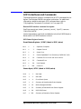
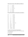
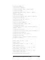
SCPI Interfaces and Commands . . . . . . . . . . . . . . . . . . . . . . . . . . . . . . . . . . . . . . . . . . . . . .4-247
5. Applications and Example Programs
Overview . . . . . . . . . . . . . . . . . . . . . . . . . . . . . . . . . . . . . . . . . . . . . . . . . . . . . . . . . . . . . . . . . . .5-2
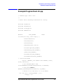
Example Program RunList.cpp . . . . . . . . . . . . . . . . . . . . . . . . . . . . . . . . . . . . . . . . . . . . . . . . .5-3
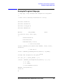
Example Program Step.cpp . . . . . . . . . . . . . . . . . . . . . . . . . . . . . . . . . . . . . . . . . . . . . . . . . . . .5-5
Working with Lists (A Programmer’s Model) . . . . . . . . . . . . . . . . . . . . . . . . . . . . . . . . . . . . . .5-6
List Modes - Controlled by the featureBits Parameter . . . . . . . . . . . . . . . . . . . . . . . . . . . . . .5-7
featureBits Parameter . . . . . . . . . . . . . . . . . . . . . . . . . . . . . . . . . . . . . . . . . . . . . . . . . . . . . . . .5-8
Trigger Input Mode . . . . . . . . . . . . . . . . . . . . . . . . . . . . . . . . . . . . . . . . . . . . . . . . . . . . . . . . .5-10
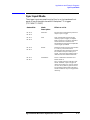
Sync Input Mode. . . . . . . . . . . . . . . . . . . . . . . . . . . . . . . . . . . . . . . . . . . . . . . . . . . . . . . . . . . .5-11
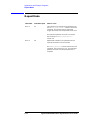
Repeat Mode . . . . . . . . . . . . . . . . . . . . . . . . . . . . . . . . . . . . . . . . . . . . . . . . . . . . . . . . . . . . . . .5-12
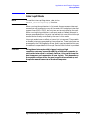
Interrupt Mode . . . . . . . . . . . . . . . . . . . . . . . . . . . . . . . . . . . . . . . . . . . . . . . . . . . . . . . . . . . . .5-13
Input and Output Triggers . . . . . . . . . . . . . . . . . . . . . . . . . . . . . . . . . . . . . . . . . . . . . . . . . . .5-15
Trig In . . . . . . . . . . . . . . . . . . . . . . . . . . . . . . . . . . . . . . . . . . . . . . . . . . . . . . . . . . . . . . . . . . . .5-16
Sync In . . . . . . . . . . . . . . . . . . . . . . . . . . . . . . . . . . . . . . . . . . . . . . . . . . . . . . . . . . . . . . . . . . .5-17
Trig Out. . . . . . . . . . . . . . . . . . . . . . . . . . . . . . . . . . . . . . . . . . . . . . . . . . . . . . . . . . . . . . . . . . .5-18
Sync Out . . . . . . . . . . . . . . . . . . . . . . . . . . . . . . . . . . . . . . . . . . . . . . . . . . . . . . . . . . . . . . . . . .5-19
Synthesizer Switching Speeds . . . . . . . . . . . . . . . . . . . . . . . . . . . . . . . . . . . . . . . . . . . . . . . . .5-20
Assist Processor Time . . . . . . . . . . . . . . . . . . . . . . . . . . . . . . . . . . . . . . . . . . . . . . . . . . . . . .5-20
Switch/Blanking Time. . . . . . . . . . . . . . . . . . . . . . . . . . . . . . . . . . . . . . . . . . . . . . . . . . . . . .5-20
Settling Time . . . . . . . . . . . . . . . . . . . . . . . . . . . . . . . . . . . . . . . . . . . . . . . . . . . . . . . . . . . . .5-23
Dwell Time. . . . . . . . . . . . . . . . . . . . . . . . . . . . . . . . . . . . . . . . . . . . . . . . . . . . . . . . . . . . . . .5-25
Timing Example - Putting It All Together . . . . . . . . . . . . . . . . . . . . . . . . . . . . . . . . . . . . . . .5-26
6. Specifications and Characteristics
Specifications and Characteristics . . . . . . . . . . . . . . . . . . . . . . . . . . . . . . . . . . . . . . . . . . . . . .6-2
Options. . . . . . . . . . . . . . . . . . . . . . . . . . . . . . . . . . . . . . . . . . . . . . . . . . . . . . . . . . . . . . . . . . .6-3
Output . . . . . . . . . . . . . . . . . . . . . . . . . . . . . . . . . . . . . . . . . . . . . . . . . . . . . . . . . . . . . . . . . . .6-4
Unwanted Signals . . . . . . . . . . . . . . . . . . . . . . . . . . . . . . . . . . . . . . . . . . . . . . . . . . . . . . . . . .6-6
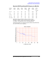
Absolute SSB Phase Noise (All Values are in dBc/Hz) . . . . . . . . . . . . . . . . . . . . . . . . . . . . .6-9
Power Supply Requirements . . . . . . . . . . . . . . . . . . . . . . . . . . . . . . . . . . . . . . . . . . . . . . . .6-10
AM Modulation . . . . . . . . . . . . . . . . . . . . . . . . . . . . . . . . . . . . . . . . . . . . . . . . . . . . . . . . . . .6-10
FM Modulation . . . . . . . . . . . . . . . . . . . . . . . . . . . . . . . . . . . . . . . . . . . . . . . . . . . . . . . . . . .6-10
Pulse Modulation (Low Band 560 MHz < 2 GHz) . . . . . . . . . . . . . . . . . . . . . . . . . . . . . . . .6-11
Pulse Modulation (High Band 2 GHz - 20 GHz) . . . . . . . . . . . . . . . . . . . . . . . . . . . . . . . . .6-12
I/Q Modulation (Option UNG Only). . . . . . . . . . . . . . . . . . . . . . . . . . . . . . . . . . . . . . . . . . .6-13
List Mode Characteristics. . . . . . . . . . . . . . . . . . . . . . . . . . . . . . . . . . . . . . . . . . . . . . . . . . .6-13
VXI Characteristics. . . . . . . . . . . . . . . . . . . . . . . . . . . . . . . . . . . . . . . . . . . . . . . . . . . . . . . .6-14
Contents-9
Contents
General Specifications . . . . . . . . . . . . . . . . . . . . . . . . . . . . . . . . . . . . . . . . . . . . . . . . . . . . . 6-14
Declaration of Conformity (According to ISO/IEC Guide 22 and EN 45014). . . . . . . . . . . . 6-15
Contacting Agilent Technologies. . . . . . . . . . . . . . . . . . . . . . . . . . . . . . . . . . . . . . . . . . . . . . . 6-16
Agilent Technologies Service Centers. . . . . . . . . . . . . . . . . . . . . . . . . . . . . . . . . . . . . . . . . . . 6-16
Adobe Acrobat Reader or QuickTime Software Downloads . . . . . . . . . . . . . . . . . . . . . . . . . 6-18
Contents-10
1
Installation
Agilent E6432A Microwave Synthesizer User’s Guide
1-1
Installation
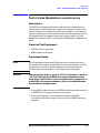
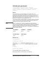
Overview
Overview
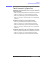
In this chapter, you will learn about:
• Hardware and software requirements prior to installation
• Installation of the E6432A microwave synthesizer
• Folders and files supplied with the E6432A VXIplug&play driver
• Typical equipment configurations
Prior to Installation of the E6432A
Prior to installation of the E6432A microwave synthesizer, items listed
as A through G must be completed as detailed in the section titled
“Hardware and Software Requirements Prior to Installation” on page
1-3. If you have problems or questions regarding the processes for items
A through G, refer to the manufacturer’s documentation for the product
in question.
1-2
Agilent E6432A Microwave Synthesizer User’s Guide
Installation
Hardware and Software Requirements Prior to Installation
Hardware and Software Requirements
Prior to Installation
Year 2000 (Y2K) Compliancy
Microsoft Corporation states that the Y2K compliant version of
Windows NT uses Service Pack 4. Although the E6432A VXIplug&play
driver has been tested and found to be Y2K compliant using Service
Pack 4, there may be some additional requirements for revision of the
Windows NT operating system to make it Y2K compliant. Additional
information related to Y2K Compliancy can be obtained using the
Internet at: http://www.microsoft.com
The E6432A VXIplug&play driver requires the following hardware and
software:
❏ WIN NT 4.0 Framework
• Windows NT 4.0 computer with Service Pack 3 or higher
• Minimum of 32 MB of RAM or higher
• CD-ROM drive
❏ Agilent E8403A C-size VXI mainframe or equivalent
❏ One of the following Slot 0 Modules:
• Agilent E8491B IEEE-1394 PC Link to VXI - Using a PCI to
IEEE-1394 Interface
— Agilent Technologies E2094G I/O library version G.02.02
(which contains VISA 1.1) or higher
• Agilent E623x VXI Embedded PC Controller or equivalent
— Agilent E2094G I/O library version G.02.02 (which
contains Agilent Technologies VISA 1.1) or higher
• NI VXI-MXI-2 - Using a PCI-MXI-2 Interface
— National Instruments VISA I/O library version 2.0 or higher
❏ E6432A driver revision A.01.00 or higher
Agilent E6432A Microwave Synthesizer User’s Guide
1-3
Installation
Hardware and Software Requirements Prior to Installation
Prior to Installation of the E6432A
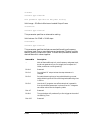
Prior to installation of the E6432A microwave synthesizer, the following
items listed as A through G must be completed. If you have problems or
questions regarding the processes for items A through G, refer to the
manufacturer’s documentation for the product in question.
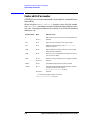
A. Set up a C-size VXI mainframe.
If you have problems or questions regarding the set up process, refer
to the manufacturer’s documentation that came with the VXI
mainframe being used.
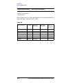
The VXI mainframe must have at least four or five empty slots. The
actual number of empty slots that are required depends on the Slot 0
module being used and the number of E6432A
microwave synthesizers being used. The Slot 0 module requires
either one or two empty slots and each E6432A
microwave synthesizer requires three empty slots. (For equipment
configuration examples, refer to “Typical Equipment Configurations”
on page 1-19.)
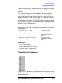
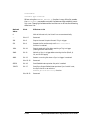
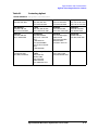
Slots Required
One Slot 0 Module Being Used
One Slot
Agilent E8491B IEEE-1394 PC Link to VXI
- Using a PCI to IEEE-1394 Interface
Two Slots
Agilent E623x VXI Embedded PC Controller or
equivalent
One Slot
NI VXI-MXI-2 - Using a PCI-MXI-2 Interface
Slots Required
One Module Being Used
Three Slots
1-4
E6432A microwave synthesizer
Agilent E6432A Microwave Synthesizer User’s Guide
Installation
Hardware and Software Requirements Prior to Installation
B. Turn power OFF to the C-size VXI mainframe and install the
Slot 0 module being used.
If you have problems or questions regarding the Slot 0 module
installation process, refer to the manufacturer’s documentation that
came with the Slot 0 module being used.
CAUTION
Do not turn power ON to the C-size VXI mainframe until you
make all peripheral connections to the Slot 0 module being
used. (Refer to the manufacturer’s documentation that came
with the Slot 0 module being used for details and explanations.)
C. Set up a Windows NT computer.
If you have problems or questions regarding the set up process, refer
to the manufacturer’s documentation that came with the
Windows NT computer being used.
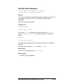
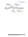
D. Turn power OFF to the Windows NT computer and install the PC
interface card being used.
If you have problems or questions regarding the PCI interface card
installation or connection process, refer to the manufacturer’s
documentation that came with the PCI interface card being used.
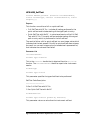
PCI Interface Card
Being Used
One Slot 0 Module Being Used
PCI to IEEE-1394
Interface
Agilent E8491B IEEE-1394 PC Link to VXI
None Required
Agilent E623x VXI Embedded PC Controller or
equivalent
PCI-MXI-2 Interface
National Instruments VXI-MXI-2
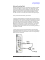
E. Connect the interface cable between the PCI interface card and the
Slot 0 module being used.
F. Turn power ON to the Windows NT computer and the C-size VXI
mainframe.
Agilent E6432A Microwave Synthesizer User’s Guide
1-5
Installation
Hardware and Software Requirements Prior to Installation
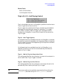
G. Select one of the following three options:
Depending on the Slot 0 module being used, either Agilent
Technologies I/O library (which contains Agilent Technologies VISA)
or National Instruments VISA library is used. Because the VISA
libraries that Agilent Technologies and National Instruments
support are slightly different in their current form, only one can be
used at a given time. The file, Visa32.dll is replaced by either the
Agilent Technologies or National Instruments version. The one that
is required, depends on the Slot 0 module being used.
❏ (Option 1) Install the Agilent Technologies I/O library (which
contains Agilent Technologies VISA) when using:
• Slot 0 Module (Agilent E8491B IEEE-1394 PC Link to VXI) Using a PCI to IEEE-1394 Interface
❏ (Option 2) Run the pre-installed Agilent Technologies I/O library
(which contains Agilent Technologies VISA) when using:
• Slot 0 Module (Agilent E623x VXI Embedded PC Controller or
equivalent)
❏ (Option 3) Install the National Instruments VISA library when
using:
• Slot 0 Module (NI VXI-MXI-2) - Using a PCI-MXI-2 Interface
1-6
Agilent E6432A Microwave Synthesizer User’s Guide
Installation
(Option 1) Install the Agilent Technologies I/O Library (which contains
Agilent Technologies VISA 1.1)
(Option 1) Install the Agilent Technologies I/O
Library (which contains Agilent Technologies
VISA 1.1)
Install the Agilent Technologies I/O library from the CD that came with
the Slot 0 module being used. If you have problems or questions
regarding the installation process, refer to the manufacturer’s
documentation that came with the Slot 0 module being used. Additional
information related to this product can be obtained using the Internet
at: http://www.agilent.com
• If using Slot 0 Module (Agilent E8491B IEEE-1394 PC Link to VXI) Using a PCI to IEEE-1394 Interface, the following must be
performed during the installation process of the I/O library:
a. Check the box labeled, “Install Agilent E8491 VXI Components.”
(This installs code for the PCI to IEEE-1394 interface card.)
b. Check the box labeled, “Configure interfaces automatically”.
(If this box is not checked, you can manually configure the
PCI to IEEE-1394 interface card using the I/O Config utility
located in the I/O Libraries program folder.
The I/O Config utility is used by the I/O Libraries to configure
instrument I/O interfaces. An interface must be configured with
the I/O Config utility before it can be used with the I/O Libraries.)
c. Reboot the Windows NT computer and VXI mainframe so that
changes take effect.
d. Perform the steps describing “Installation of the E6432A
Microwave Synthesizer” on page 1-11.
Agilent E6432A Microwave Synthesizer User’s Guide
1-7
Installation
(Option 2) Run the Pre-Installed Agilent Technologies I/O Library (which
contains Agilent Technologies VISA 1.1)
(Option 2) Run the Pre-Installed Agilent
Technologies I/O Library (which
contains Agilent Technologies VISA 1.1)
The Windows NT operating system software comes pre-installed on the
embedded controller’s hard disk along with controller drivers and
utilities software. Installation of the Agilent Technologies I/O library
from the CD that comes with the Slot 0 module being used only has to
be performed if there is ever a need to re-install the software. If you
have problems or questions regarding the installation process, refer to
the manufacturer’s documentation that came with the Slot 0 module
being used. Additional information related to this product can be
obtained using the Internet at: http://www.agilent.com
• If using Slot 0 Module (Agilent E6233A, 4A, 5A VXI Embedded PC
Controller or equivelant) the following must be performed after the
embedded controller has been installed into the C-size VXI
mainframe.
CAUTION
Do not turn power ON to the C-size VXI mainframe and the
Agilent E623x VXI Embedded Controller until you make all
connections to the peripherals. (Refer to the manufacturer’s
documentation that came with the Slot 0 module being used for
details and explanations.)
Use extreme caution when connecting peripheral cables to the
embedded controller. The I/O base board of the embedded
controller provides power for peripheral devices through
different pins. Making incorrect connections can damage the
board and may damage the peripheral device being connected.
a. Connect any desired peripherals (keyboard, mouse, serial ports,
monitor, and SCSI devices) and turn power ON to the C-size VXI
mainframe. When the system is powered on, the embedded
controller automatically runs the Startup Resource Manager
(SURM).
b. Before the Windows NT software (including VISA) can be used, the
I/O Config utility must be run.
While running the I/O Config utility, check the box labeled,
“Configure interfaces automatically.”
1-8
Agilent E6432A Microwave Synthesizer User’s Guide
Installation
(Option 2) Run the Pre-Installed Agilent Technologies I/O Library (which
contains Agilent Technologies VISA 1.1)
The I/O Config utility is used by the I/O Libraries to configure
instrument I/O interfaces. An interface must be configured before it
can be used with the I/O Libraries.
c. Reboot the C-size VXI mainframe so that changes take effect.
d. Perform the steps describing “Installation of the E6432A Microwave
Synthesizer” on page 1-11.
Agilent E6432A Microwave Synthesizer User’s Guide
1-9
Installation
(Option 3) Install the National Instruments VISA Library
(Option 3) Install the National Instruments
VISA Library
Install the National Instruments VISA library from the CD that came
with the Slot 0 module being used. If you have problems or questions
regarding the installation process, refer to the manufacturer’s
documentation that came with the Slot 0 module being used. Additional
information related to this product can be obtained using the Internet
at: http://www.natinst.com
• If using Slot 0 Module (NI VXI-MXI-2) - Using a PCI-MXI-2
Interface, the following must be performed after the National
Instruments VISA library installation process:
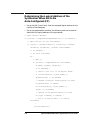
a. Run the program T&M Explorer [Test and Measurement Explorer].
T&M Explorer is available from the Windows NT Start taskbar by
selecting: Start/Programs/Ni-vxi/T&M Explorer.
b. Select the PCI-MXI-2 Interface.
c. Right-mouse click and select Hardware Configuration.
d. Select the PCI tab.
e. Select the checkbox, Enable low-level register access API
support.
f. Select the down arrow on the User window size entry box and
select 256 KB.
g. Select OK.
h. Exit T&M Explorer.
i. Reboot the Windows NT computer and VXI mainframe so that
changes take effect.
j. Run Resman (VXI Resource Manager) and verify that the Slot 0
module being used is found.
k. Perform the steps describing “Installation of the E6432A Microwave
Synthesizer” on page 1-11.
1-10
Agilent E6432A Microwave Synthesizer User’s Guide
Installation
Installation of the E6432A Microwave Synthesizer
Installation of the E6432A Microwave
Synthesizer
Prior to Installation of the E6432A
Prior to installation of the E6432A microwave synthesizer, items listed
as A through G must be completed as called out in “Hardware and
Software Requirements Prior to Installation” on page 1-3.
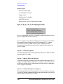
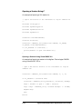
1. Set the E6432A microwave synthesizer’s logical address.
The unit is factory set to be Auto Configured at address 255 (FF).
Agilent VEE requires a fixed address. Factory suggestion is address
210 (D2).
2. Turn power OFF to the C-size VXI mainframe and install the
E6432A microwave synthesizer.
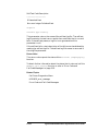
3. Turn power ON to the C-size VXI mainframe and run one of the
following:
Run…
One Slot 0 Module Being Used
I/O Config
Agilent E8491B IEEE-1394 PC Link to VXI
- Using a PCI to IEEE-1394 Interface
Resman
NI VXI-MXI-2 - Using a PCI-MXI-2 Interface
SURM
Agilent E623x VXI Embedded PC Controller or
equivalent
4. Install the E6432A VXIplug&play driver software from the supplied
CD.
If the CD does not auto install, run Setup.exe from the Windows NT
Start taskbar.
Agilent E6432A Microwave Synthesizer User’s Guide
1-11
Installation
Installation of the E6432A Microwave Synthesizer
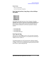
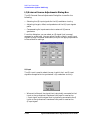
5. Start the E6432A microwave synthesizer Soft Front Panel by
double-clicking the icon displayed or access it through the Windows
NT Start taskbar.
The Setup.exe program installs the E6432A VXIplug&play driver
in the VXIpnp\WinNT folder by default and does not allow the
destination folder to be changed during installation.
The VXIpnp\WinNT folder is located under the directory path that
you selected when installing the VISA library. To change the location
of these folders, refer to the installation procedure that was used to
install Agilent Technologies I/O library or National Instruments
VISA library; if you desire to change the directory path, the library
will need to be reinstalled before installing the E6432A
VXIplug&play driver.
If the E6432A microwave synthesizer Soft Front Panel is able to
establish communication with the hardware, the VXI address is
displayed in the title bar.
6. At this point, installation is complete and an Acceptance Test
Procedure (ATP) may be performed. The ATP is a set of manual tests
and is documented at the end of this chapter
The ATP is intended as a functionality check and is not intended for
testing against customer specifications.
For complete specifications, refer to “Specifications and
Characteristics” on page 6-1.
1-12
Agilent E6432A Microwave Synthesizer User’s Guide
Installation
Folders and Files Supplied with the E6432A VXIplug&play Driver
Folders and Files Supplied with the E6432A
VXIplug&play Driver
This section describes the folders and files that are supplied with the
VXIplug&play driver.
❏ If a VISA library is not installed, the VXIplug&play driver can only
be used in demo mode.
Demo mode is used for demonstration purposes of the graphical user
interface only, and does not require any physical connection to
hardware or the VXI bus. The Setup.exe program installs the
VXIplug&play driver in the VXIpnp\WinNT folder by default, but
allows the destination folder to be changed during installation.
If you answer yes to the “Startup Error Dialog Box,” the
VXIplug&play driver will be used in demo mode.
❏ If a VISA library is installed, the VXIplug&play driver can be used
in demo mode or run-time mode.
Run-time mode is used during normal operation of the graphical
user interface, and does require physical connections to hardware
and the VXI bus. The Setup.exe program installs the VXIplug&play
driver in the VXIpnp\WinNT folder by default, and does not allow the
destination folder to be changed during installation.
The VXIpnp\WinNT folder is located under the directory path that
you selected when installing the VISA library. To change the location
of these folders, refer to the installation procedure that was used to
install Agilent Technologies I/O library or National Instruments
VISA library; if you desire to change the directory path, the library
will need to be reinstalled before installing the E6432A
VXIplug&play driver.
After installing the VXIplug&play driver, the WinNT folder contains the
following folders and files:
Bin:
• HPE6432.dll
This dynamic link library file is the VXIplug&play driver for the
E6432A microwave synthesizer. This file is generated by compiling
the HPE6432.c file and linking it with the libHPE6432.lib file.
• HPE6432_32.dll
This dynamic link library file is a copy of the HPE6432.dll file, but is
used by the Agilent VEE and LabVIEW environments.
If you plan to customize the HPE6432.dll file, refer to the procedure:
To generate a new HPE6432.dll file
Agilent E6432A Microwave Synthesizer User’s Guide
1-13
Installation
Folders and Files Supplied with the E6432A VXIplug&play Driver
Hpe6432:
• HPE6432Types.h
This header file defines the minimum and maximum parameter
values that are used by the E6432A microwave synthesizer’s
VXIplug&play driver.
• HPE6432Errors.h
This header file defines all of the error codes that can be reported by
an E6432A microwave synthesizer.
• HPE6432.h
This header file is duplicated in this folder for convenience, but is
also located in the Include: folder.
This header file contains the function prototypes for each of the
VXIplug&play functions used by the E6432A microwave synthesizer.
• libHPE6432.h
This header file is written using C syntax and contains the function
prototypes for all low-level driver functions that are called by
E6432A VXIplug&play functions; low-level driver function names
begin with an underscore. (For example, _Close is the low-level
driver function name used by the VXIplug&play HPE6432_close
function, and its corresponding function prototype is: ViStatus
_Close(ViSession instrumentHandle);.)
• libHPE6432.lib
This library file contains all of the compiled code required to run the
low-level driver functions that are called by E6432A VXIplug&play
functions.
• HPE6432.lib
This library file is duplicated in this folder for convenience, but is
also located in the Lib/Msc: folder.
This library file contains the code required to use the HPE6432.dll
dynamic link library.
The HPE6432.dll dynamic link library is generated by compiling the
HPE6432.c source file and linking it with the libHPE6432.lib
library file. When the HPE6432.c source file is modified by the user,
it must be recompiled and linked with the libHPE6432.lib library
file to produce a new HPE6432.lib library file and new HPE6432.dll
dynamic link library.
1-14
Agilent E6432A Microwave Synthesizer User’s Guide
Installation
Folders and Files Supplied with the E6432A VXIplug&play Driver
• HPE6432.c
This is the C source code for the E6432A VXIplug&play driver. This
file is compiled and linked with the libHPE6432.lib file to generate
the HPE6432.lib library file and the HPE6432.dll dynamic link
library.
• HPE6432_panel.uir
This file defines the soft front panel user interface that is used by the
E6432A microwave synthesizer.
• HPE6432.exe
This file generates the soft front panel that controls the E6432A
microwave synthesizer’s functionality.
• HPE6432.bas
This header file is duplicated in this folder for convenience, but is
also located in the Include: folder.
This header file is written using Visual Basic 6.0 syntax and
contains the function prototypes for all E6432A VXIplug&play
functions.
• HPE6432.frm
This file contains an example soft front panel that can be used
within the Visual Basic 6.0 environment to control the E6432A
microwave source. This file uses the HPE6432.bas header file.
• Uninstall.exe
This file is used to uninstall the VXIplug&play driver and all of its
related files from the WinNT folder. Install.log keeps track of all
installation settings.
• HPE6432.fp
This file documents the VXIplug&play commands and their
parameters. It is used to supply on-line help information to the
Agilent VEE and LabVIEW environments.
Agilent E6432A Microwave Synthesizer User’s Guide
1-15
Installation
Folders and Files Supplied with the E6432A VXIplug&play Driver
Help:
• Agte6432.htm
This file is used to generate a cross-platform Help system for the
VXIplug&play driver that runs on both Unix and Windows platforms
using an internet browser. The Help system requires internet
browsers that are Java enabled with Java 1.02 and above, can use
Microsoft Internet Explorer 4.0 and above, or Netscape
Navigator 4.0 and above.
In this Help folder, there may also be files that end with a .pdf that
require Adobe Acrobat Reader and files that end with a .mov that
require QuickTime software. To get either of these pieces of
software, refer to “Adobe Acrobat Reader or QuickTime Software
Downloads” on page 6-18.
Include:
• HPE6432.h
This header file contains the function prototypes for each of the
VXIplug&play functions used by the E6432A microwave synthesizer.
• HPE6432.bas
This header file is written using Visual Basic 6.0 syntax and
contains the function prototypes for all E6432A VXIplug&play
functions.
Lib/Msc (Microsoft C Libraries):
• HPE6432.lib
This library file contains the code required to use the HPE6432.dll
dynamic link library.
The HPE6432.dll dynamic link library is generated by compiling the
HPE6432.c source file and linking it with the libHPE6432.lib
library file. When the HPE6432.c source file is modified by the user,
it must be recompiled and linked with the libHPE6432.lib library
file to produce a new HPE6432.lib library file and new HPE6432.dll
dynamic link library.
Agilent Technologies Visa or NIvisa library files.
• In order to use the VXIplug&play driver, either Agilent Technologies
VISA library or National Instruments VISA library must first be
installed; the VISA library that you install depends on the Slot 0
module being used. For further information, refer to “Hardware and
Software Requirements Prior to Installation” on page 1-3.
1-16
Agilent E6432A Microwave Synthesizer User’s Guide
Installation
Folders and Files Supplied with the E6432A VXIplug&play Driver
Related Topics
• Slot 0 Module (Agilent E8491B IEE-1394 PC Link to VXI) -Using a
PCI IEE-1394 Interface.
• Slot 0 Module (NI VXI-MXI-2)- Using PCI-MXI-2 Interface Module.
• Slot 0 Module (Agilent E6432, 4A, 5a VXI Embedded PC Controller
or equivalent).
• Startup Error Dialog Box.
Agilent E6432A Microwave Synthesizer User’s Guide
1-17
Installation
To Generate a New HPE6432.dll File
To Generate a New HPE6432.dll File
The HPE6432.dll dynamic link library file is the E6432A
microwave synthesizer’s VXIplug&play driver.
The HPE6432.dll dynamic link library is generated by compiling the
HPE6432.c source file and linking it with the libHPE6432.lib library
file. When the HPE6432.c source file is modified by the user, it must be
recompiled and linked with the libHPE6432.lib library file to produce
a new HPE6432.lib library file and new HPE6432.dll dynamic link
library file.
The following list of files are required to generate a new HPE6432.dll
file:
• HPE6432Types.h
• HPE6432Errors.h
• HPE6432.h
• libHPE6432.h
• libHPE6432.lib
• HPE6432.lib
• HPE6432.def
This file defines the names of all entry points into the HPE6432.dll file
that is generated during the linking process.
• HPE6432.c
• cvidef.h – This file is not part of the VXIplug&play driver.
• cvirte.h – This file is not part of the VXIplug&play driver.
• visatype.h – This file is not part of the VXIplug&play driver.
1-18
Agilent E6432A Microwave Synthesizer User’s Guide
Installation
Typical Equipment Configurations
Typical Equipment Configurations
Slot 0 Module (Agilent E8491B IEEE-1394 PC Link to VXI) - Using a PCI
to IEEE-1394 Interface
• Used with Three Agilent E1445A Arbitrary Waveform Synthesizers
• Used with Three Racal 3152 Arbitrary Waveform Generators
• Used with One Racal 3153 Triple Arbitrary Waveform Generator
• Used with Three-Pair of E6432A and Racal 3153 to Produce Radar
Simulations
Slot 0 Module (NI VXI-MXI-2) - Using a PCI-MXI-2 Interface
• Used with Three E1445A Arbitrary Waveform Synthesizers
• Used with Three Racal 3152 Arbitrary Waveform Generators
• Used with One Racal 3153 Triple Arbitrary Waveform Generator
• Used with Three-Pair of E6432A and Racal 3153 to Produce Radar
Simulations
Slot 0 Module (Agilent E6233A, 4A, 5A VXI Embedded PC Controller)
• Used with Three Agilent E1445A Arbitrary Waveform Synthesizers
• Used with Three Racal 3152 Arbitrary Waveform Generators
• Used with One Racal 3153 Triple Arbitrary Waveform Generator
Agilent E6432A Microwave Synthesizer User’s Guide
1-19
Installation
Agilent E8491B IEEE-1394 - Used with Three E1445A Arbitrary Waveform
Synthesizers
Agilent E8491B IEEE-1394 - Used with Three
E1445A Arbitrary Waveform Synthesizers
Related Topics
Slot 0 Module (Agilent E8491B IEEE-1394 PC Link to VXI) - Using a
PCI to IEEE-1394 Interface
Typical Equipment Configurations
1-20
Agilent E6432A Microwave Synthesizer User’s Guide
Installation
Agilent E8491B IEEE-1394 - Used with Three Racal 3152 Arbitrary Waveform
Generators
Agilent E8491B IEEE-1394 - Used with Three
Racal 3152 Arbitrary Waveform Generators
Related Topics
Slot 0 Module (Agilent E8491B IEEE-1394 PC Link to VXI) - Using a
PCI to IEEE-1394 Interface
Typical Equipment Configurations
Agilent E6432A Microwave Synthesizer User’s Guide
1-21
Installation
Agilent E8491B IEEE-1394 - Used with One Racal 3153 Triple Arbitrary
Waveform Generator
Agilent E8491B IEEE-1394 - Used with One
Racal 3153 Triple Arbitrary Waveform
Generator
Related Topics
Slot 0 Module (Agilent E8491B IEEE-1394 PC Link to VXI) - Using a
PCI to IEEE-1394 Interface
Typical Equipment Configurations
1-22
Agilent E6432A Microwave Synthesizer User’s Guide
Installation
Agilent E8491B IEEE-1394 - Used with Three-Pair of E6432A and Racal 3153
to Produce Radar Simulations
Agilent E8491B IEEE-1394 - Used with
Three-Pair of E6432A and Racal 3153 to
Produce Radar Simulations
Related Topics
Slot 0 Module (Agilent E8491B IEEE-1394 PC Link to VXI) - Using a
PCI to IEEE-1394 Interface
Typical Equipment Configurations
Agilent E6432A Microwave Synthesizer User’s Guide
1-23
Installation
Slot 0 Module (NI VXI-MXI-2)- Using a PCI-MXI-2 Interface
Slot 0 Module (NI VXI-MXI-2)- Using a
PCI-MXI-2 Interface
• Used with Three Agilent E1445A Arbitrary Waveform Synthesizers
• Used with Three Racal 3152 Arbitrary Waveform Generators
• Used with One Racal 3153 Triple Arbitrary Waveform Generator
• Used with Three-Pair of E6432 and Racal 3153 to Produce Radar
Simulations
Related Topics
Typical Equipment Configurations
1-24
Agilent E6432A Microwave Synthesizer User’s Guide
Installation
NI VXI-MXI-2 - Used with Three Agilent E1445A Arbitrary Waveform
Synthesizers
NI VXI-MXI-2 - Used with Three Agilent
E1445A Arbitrary Waveform Synthesizers
Related Topics
Slot 0 Module (NI VXI-MXI-2) - Using a PCI-MXI-2 Interface
Typical Equipment Configurations
Agilent E6432A Microwave Synthesizer User’s Guide
1-25
Installation
NI VXI-MXI-2 - Used with Three Racal 3152 Arbitrary Waveform Generators
NI VXI-MXI-2 - Used with Three Racal 3152
Arbitrary Waveform Generators
Related Topics
Slot 0 Module (NI VXI-MXI-2) - Using a PCI-MXI-2 Interface
Typical Equipment Configurations
1-26
Agilent E6432A Microwave Synthesizer User’s Guide
Installation
NI VXI-MXI-2 - Used with One Racal 3153 Triple Arbitrary Waveform
Generator
NI VXI-MXI-2 - Used with One Racal 3153
Triple Arbitrary Waveform Generator
Related Topics
Slot 0 Module (NI VXI-MXI-2) - Using a PCI-MXI-2 Interface
Typical Equipment Configurations
Agilent E6432A Microwave Synthesizer User’s Guide
1-27
Installation
NI VXI-MXI-2 - Used with Three-Pair of E6432A and Racal 3153 to Produce
Radar Simulations
NI VXI-MXI-2 - Used with Three-Pair of E6432A
and Racal 3153 to Produce Radar Simulations
Related Topics
Slot 0 Module (NI VXI-MXI-2) - Using a PCI-MXI-2 Interface
Typical Equipment Configurations
1-28
Agilent E6432A Microwave Synthesizer User’s Guide
Installation
Slot 0 Module (Agilent E6233A, 4A, 5A VXI Embedded PC Controller)
Slot 0 Module (Agilent E6233A, 4A, 5A VXI
Embedded PC Controller)
• Used with Three Agilent E1445A Arbitrary Waveform Synthesizers
• Used with Three Racal 3152 Arbitrary Waveform Generators
• Used with One Racal 3153 Triple Arbitrary Waveform Generator
Related Topics
Typical Equipment Configurations
Agilent E6432A Microwave Synthesizer User’s Guide
1-29
Installation
Agilent E6233A, 4A, 5A VXI Embedded PC Controller - Used with Three
Agilent E1445A Arbitrary Waveform Synthesizers
Agilent E6233A, 4A, 5A VXI Embedded PC
Controller - Used with Three Agilent E1445A
Arbitrary Waveform Synthesizers
Related Topics
Slot 0 Module (Agilent E6233A, 4A, 5A VXI Embedded PC
Controller)
Typical Equipment Configurations
1-30
Agilent E6432A Microwave Synthesizer User’s Guide
Installation
Agilent E6233A, 4A, 5A VXI Embedded PC Controller - Used with Three Racal
3152 Arbitrary Waveform Generators
Agilent E6233A, 4A, 5A VXI Embedded PC
Controller - Used with Three Racal 3152
Arbitrary Waveform Generators
Related Topics
Slot 0 Module (Agilent E6233A, 4A, 5A VXI Embedded PC
Controller)
Typical Equipment Configurations
Agilent E6432A Microwave Synthesizer User’s Guide
1-31
Installation
Agilent E6233A, 4A, 5A VXI Embedded PC Controller - Used with One Racal
3153 Triple Arbitrary Waveform Generator
Agilent E6233A, 4A, 5A VXI Embedded PC
Controller - Used with One Racal 3153 Triple
Arbitrary Waveform Generator
Related Topics
Slot 0 Module (Agilent E6233A, 4A, 5A VXI Embedded PC
Controller)
Typical Equipment Configurations
1-32
Agilent E6432A Microwave Synthesizer User’s Guide
Installation
Agilent E6432A Acceptance Test Procedure
Agilent E6432A Acceptance Test Procedure
After satisfying the requirements and steps detailed in the sections
titled “Hardware and Software Requirements Prior to Installation” on
page 1-3 and “Installation of the E6432A Microwave Synthesizer” on
page 1-11, the following Acceptance Test Procedure (ATP) may be
performed.
This manual ATP is intended as a functionality check, and is not
intended for testing against customer specifications. The ATP consists
of seven tests that can be performed in under three hours with a
minimum of test equipment.
Acceptance Tests
• Test 1. Maximum Power and Power Flatness
• Test 2. Linear AM Accuracy
• Test 3. FM Accuracy
• Test 4. Pulse Modulation Level Accuracy
• Test 5. Harmonics
• Test 6. External Leveling
• Test 7. I/Q Functionality
Required Test Equipment or Equivalent
• 8563E spectrum analyzer
• 33120A function generator
• E4418A power meter
• E4413A power sensor
• 33330C detector
• Krytar directional coupler with 16 dB coupling factor
Agilent E6432A Microwave Synthesizer User’s Guide
1-33
Installation
Test 1. Maximum Power and Power Flatness
Test 1. Maximum Power and Power Flatness
Description
This test sets the E6432A microwave synthesizer to its maximum
power at two frequencies, one in low band and one in high band. A
power meter and sensor are used to measure maximum power at both
frequencies. Power flatness is checked in low band, high band, and then
over the entire frequency range. A delta power measurement is made to
check flatness.
Required Test Equipment
• EPM-441A (E4418A) single channel power meter
• ECP-E26A (E4413A) 50 MHz to 26.5 GHz power sensor
• 11730A power sensor cable
Equipment Setup
NOTE
All test equipment requires a 30 minute warm-up period to ensure
warranted performance. The E6432A microwave synthesizer must be
connected to an external 10 MHz reference. Ensure that external
10 MHz reference is selected in the Configuration Dialog Box
E4418A Setup Summary
E4418A Setup Details
1. Using the 11730A power sensor cable, connect
the E4413A power sensor to the E4418A
power meter.
Mode dBm
2. On the E4418A, press dBm/W, then press dBm.
Zero power sensor
3. Press Zero/Cal, then press Zero.
4. Connect the E4413A power sensor to the
E4418A POWER REF output.
Cal power sensor
5. Press Zero/Cal, then Cal. The E4418A
automatically reads the E4413A calibration
table.
6. Connect the E4413A power sensor to the
E6432A RF output.
1-34
Agilent E6432A Microwave Synthesizer User’s Guide
Installation
Test 1. Maximum Power and Power Flatness
E6432A Setup
Summary
E6432A Setup Details
Obtain option
information
1. Obtain option information by selecting “About
E6432A” from the pull down Help menu on the
E6432A Soft Front Panel.
Agilent E6432A Microwave Synthesizer User’s Guide
1-35
Installation
Test 1. Maximum Power and Power Flatness
Maximum Power Measurement
E6432A
E6432A
Measurement Summary Measurement Details
Frequency 50 MHz
1. From the 6432A Soft Front Panel, select the
Frequency entry box and enter 50 MHz.
RF On
2. Select the RF OFF button. The green indicator
and the message RF ON should come on.
Maximum Output Power
3. Select the Output Power entry box. Enter the
maximum power for your model from the
Maximum Power Table shown below.
Measure power
4. Enter the power meter reading in the
Maximum Power Table under Measured Power.
Note: Ensure that the Unleveled indicator does
not illuminate for any of the measurements. If
it is illuminated, it indicates a failure.
Frequency 20 GHz
Table 1-1
5. Select the Frequency entry box and enter
20 GHz and complete the table.
Maximum Power Table
Model
Test Frequency
Standard
50 MHz
+17 dBm
20 GHz
+17 dBm
50 MHz
+16 dBm
20 GHz
+16 dBm
50 MHz
+14 dBm
20 GHz
+17 dBm
50 MHz
+13 dBm
20 GHz
+16 dBm
50 MHz
+17 dBm
20 GHz
+20 dBm
50 MHz
+16 dBm
20 GHz
+19 dBm
UNF, 1E1, and UNH 50 MHz
+13 dBm
20 GHz
+19 dBm
1E1
UNH
1E1 and UNH
UNF
UNF and 1E1
1-36
Measured Power
Test Limits
Agilent E6432A Microwave Synthesizer User’s Guide
Installation
Test 1. Maximum Power and Power Flatness
Power Flatness Measurement
Measurement Summary Measurement Details
E6432A
1. If the 6432A is a Standard model, enter +7 dBm
in the Output Power entry box. If the E6432A is
an Option 1E1, enter –35 dBm in the Output
Power entry box.
+7 dBm (STD) or
–35 dBm (1E1)
2. Press Rel/Offset, Rel, then Ref on the E4418A.
The power level at 20 GHz is then used as a
reference.
E4418A Mode
Rel/Offset, Rel, Ref
E6432A
Frequency 2 GHz
Record E4418A reading
Frequency 50 MHz
Record E4418A reading
Rel/Offset, Rel, Ref
E6432A
Frequency 1.99 GHz
Record E4418A reading
Model
4. On the E6432A, select the Frequency entry box
and enter 50 MHz. The reading on the E4418A
is the leveled power flatness from 50 MHz to
20 GHz. Record this value in the Power Flatness
Table shown below.
5. Press Rel/Offset, Rel, and then Ref on the
E4418A. The power level at 50 MHz is then used
as a reference.
E4418A Mode
Table 1-2
3. On the E6432A, select the Frequency entry box
and enter 2 GHz. The reading on the E4418A is
the leveled power flatness from 2 GHz to
20 GHz. Record the value in the Power Flatness
Table shown below under the D Power Measured
column.
6. On the E6432A, select the Frequency entry box
and enter 1.99 GHz. The reading on the E4418A
is the leveled power flatness from 50 MHz to less
than 2 GHz. Record this value in the Power
Flatness Table shown below.
Power Flatness Table
Test Frequencies ∆ Power Measured
Standard 2 GHz to 20 GHz
1E1
Test Limits
± 3.3 dB
50 MHz to 20 GHz
± 3.3 dB
50 MHz < 2 GHz
± 3.3 dB
2 GHz to 20 GHz
± 5.5 dB
50 MHz to 20 GHz
± 5.5 dB
50 MHz < 2 GHz
± 5.5 dB
Agilent E6432A Microwave Synthesizer User’s Guide
1-37
Installation
Test 2. AM Accuracy
Test 2. AM Accuracy
Description
The E6432A microwave synthesizer is configured for linear AM and a
spectrum analyzer is used to measure sidebands. An external function
generator drives the E6432A AM input. The test is performed at carrier
frequencies of 10 MHz and 20 GHz with AM depths of 10% and 90%.
Two AM rates are tested at 1 kHz and 100 kHz.
Required Test Equipment
• 33120A function generator
• 8563E spectrum analyzer
• BNC tee
• BNC 50-ohm load
Equipment Setup
NOTE
All test equipment requires a 30 minute warm-up period to ensure
warranted performance. The E6432A microwave synthesizer must be
connected to an external 10 MHz reference. Ensure that external
10 MHz reference is selected in the Configuration Dialog Box.
7. Connect a BNC tee to the E6432A microwave synthesizer AM input.
8. Connect a 50-ohm load to one port of the BNC tee.
9. Using a BNC cable, connect the 33120A function generator output to
the other port of the BNC tee.
NOTE
The E6432A microwave synthesizer AM input impedance is 2 kilohm
and the 33120A requires a 50-ohm load; therefore, a BNC tee and
50-ohm load are used.
10.Use a high frequency 3.5 mm cable to connect the E6432A
microwave synthesizer output to the input of the 8563E spectrum
analyzer.
1-38
Agilent E6432A Microwave Synthesizer User’s Guide
Installation
Test 2. AM Accuracy
33120A Setup Summary
33120A Setup Details
Output impedance 50 ohm
1. Press Shift and Menu keys.
2. Press the > key three times until D:Sys Menu is
displayed.
3. Press the key ∨ until 1:Out Term is displayed.
4. Press the key ∨ until 50 Ohm is displayed.
5. Press the Enter key.
1 kHz sine wave at 200 mVpp
6. Press the ~ sine wave key.
7. Press Freq, Enter Number, 1, and kHz.
8. Press the Ampl, Enter Number, 200, Shift, and
m Vpp.
Offset 0 Vdc
E6432A Setup Summary
9. Press Offset, Enter Number, 0, Shift, and m Vpp.
E6432A Setup Details
1. Start the E6432A Soft Front Panel.
Frequency 10 MHz
2. Select the Frequency entry box and enter
10 MHz.
AM On
3. Select the AM check box.
Output Power 0 dBm
4. Select Configuration from the pull down View
menu.
5. Return to the Soft Front Panel, select the
Output Power entry box, and enter 0 dBm.
Deep AM Off
Linear AM On
RF On
6. In the Configuration Dialog Box, ensure that
the Deep AM is set to Off and AM Mode is set to
Linear.
7. From the Soft Front Panel, select the RF OFF
button so that RF ON is displayed.
8563E Setup Summary
8563E Setup Details
Preset
1. Press the green Preset key.
Center Frequency 10 MHz
2. Press the Frequency key and enter 10 MHz.
Span 10 kHz
3. Press the Span key and enter 10 kHz.
Reference Level +10 dBm
4. Press the Amplitude key and enter +10 dBm for
the reference level.
Agilent E6432A Microwave Synthesizer User’s Guide
1-39
Installation
Test 2. AM Accuracy
AM Accuracy Measurement
Measurement Summary
Measurement Details
8563E
1.
On the 8563E, press the Mkr and Peak Search
keys.
Marker Delta
2.
Press the Marker Delta and Next Peak keys.
Next Peak
3.
Enter the value in the AM Accuracy Table on the
next page.
4.
Change the E6432A Frequency entry box and the
8563E to a carrier frequency of 20 GHz.
5.
Repeat the above marker measurements.
6.
Change the 33120A amplitude to 1.8 Vpp.
7.
On the E6432A, select Configuration from the pull
down View menu. Select Deep AM and set it to on.
8.
Repeat the 8563E marker measurements and
complete the 20 GHz portion of the AM Accuracy
Table for 90% depth.
9.
Change the E6432A Frequency entry box and the
8563E to a carrier frequency of 10 MHz.
10.
Repeat the above marker measurements.
11.
Change the 33120A frequency to 100 kHz to test an
AM rate of 100 kHz.
12.
Change the 8563E to a Span of 1 MHz.
13.
Repeat the 8563E marker measurement for an AM
rate of 100 kHz at 90% depth.
Mkr peak search
Center Frequency 20 GHz
E6432A
Frequency 20 GHz
8563E
Mkr peak search
Marker Delta
Next Peak
33120A
Amplitude 1.8 Vpp
E6432A
Deep AM On
8563E
Mkr peak search
Marker Delta
Next Peak
Center Frequency 10 MHz
E6432A
Frequency 10 MHz
8563E
Mkr peak search
Marker Delta
Next Peak
33120A
Frequency 100 kHz
8563E
Span 1 MHz
Mkr peak search
Marker Delta
Next Peak
Center Frequency 20 GHz
1-40
Agilent E6432A Microwave Synthesizer User’s Guide
Installation
Test 2. AM Accuracy
Measurement Summary
Measurement Details
E6432A
14.
Change the E6432A Frequency entry box and the
8563E carrier frequency to 20 GHz.
15.
Perform the 8563E marker measurements. Record
the 90% depth in the AM Accuracy Table.
16.
Change the 33120A amplitude to 200 mVpp.
17.
On the Configuration Dialog Box available from
the E6432A Soft Front Panel, select Deep AM and
set it to off.
18.
Repeat the marker measurements and complete
the AM Accuracy Table for an AM Rate of 100 kHz
and depth of 10%.
19.
Change the E6432A Frequency entry box and the
8563E to a carrier frequency of 10 MHz.
20.
Perform the 8563E marker measurements. Record
this value in the AM Accuracy Table.
Frequency 20 GHz
8563E
Mkr peak search
Marker Delta
Next Peak
33120A
Amplitude 200 mVpp
E6432A
Deep AM Off
8563E
Mkr peak search
Marker Delta
Next Peak
Center Frequency 10 MHz
E6432A
Frequency 10 MHz
8563E
Mkr peak search
Marker Delta
Next Peak
Agilent E6432A Microwave Synthesizer User’s Guide
1-41
Installation
Test 2. AM Accuracy
Table 1-3
AM Accuracy Table
Carrier Frequency
AM Rate
AM Depth
Measured
Test Limits
10 MHz
1 kHz
10%
–21.4 dB to –36.5 dB
20 GHz
1 kHz
10%
–21.4 dB to –36.5 dB
20 GHz
1 kHz
90%
–6.3 dB to –7.6 dB
10 MHz
1 kHz
90%
–6.3 dB to –7.6 dB
10 MHz
100 kHz
90%
–6.3 dB to –7.6 dB
20 GHz
100 kHz
90%
–6.3 dB to –7.6 dB
20 GHz
100 kHz
10%
–21.4 dB to –36.5 dB
10 MHz
100 kHz
10%
–21.4 dB to –36.5 dB
AM Accuracy Test Limit = ±12% and is calculated as follows:
Esb ( dB ) – Ec ( dB ) = 20 log m ⁄ 2
where:Esb = the amplitude of the AM sideband
Ec = the amplitude of the carrier
m = modulation percent expressed as a fraction
1-42
Agilent E6432A Microwave Synthesizer User’s Guide
Installation
Test 3. FM Accuracy
Test 3. FM Accuracy
Description
The E6432A and the function generator are configured for modulation
indices corresponding to Bessel nulls of Jo. The amplitude of the
function generator is varied until the carrier being monitored on the
spectrum analyzer is a minimum. The function generator amplitude is
then recorded and compared to the theoretical value to calculate the
FM accuracy error. This test is also used for testing Option 002, low
rate FM.
Equipment Required:
33120A function generator
8563E spectrum analyzer
BNC Tee
BNC 50 ohm load
Equipment Setup:
NOTE
All test equipment requires a 30 minute warm up period to ensure
warranted performance. The E6432A needs to have an external 10 MHz
reference connected. Ensure the external 10 MHz reference is selected
in the configuration pull down menu.
WARNING
Function generator amplitudes greater than or equal to +15 V or less
than or equal to –15 V applied to the FM input will cause damage to
internal circuitry. Amplitudes greater than +8 V or less than –8 V may
cause distortion.
1. Connect a BNC Tee to the E6432A FM input.
2. Connect a 50 ohm load to one port of the BNC Tee.
3. Using a BNC cable connect the 33120A output to the other port of
the BNC Tee.
Due to the E6432A FM input impedance being 2 K ohm and the
33120A wanting to see a 50 ohm load; a BNC Tee and 50 ohm load
are used.
Agilent E6432A Microwave Synthesizer User’s Guide
1-43
Installation
Test 3. FM Accuracy
4. Use a high frequency 3.5 mm cable to connect the E6432A output to
the input of the 8563E.
33120A Setup Summary
33120A Setup Details
Output impedance = 50 ohms
1. Press the “Shift” key.
Std; 200 kHz sine wave at
2.208 Vpp
2. Press the “Enter” key.
Opt 002; 1 kHz sine wave at
110.4 mVpp
3. Press the “>” key three times until “D: Sys Menu”
is displayed.
Offset = 0 Vdc
4. Press the “⁄” key and “1: Out Term” is displayed.
5. Press the “⁄” key until “50 Ohm” is displayed.
6. Press the Enter key.
7. Press the “~“ sine wave front panel key.
8. Press the Freq front panel key. Press the Enter
Number front panel key and enter the correct FM
rate for your option using the numeric keys. To enter
the number press kHz.
9. Press the Ampl front panel key. Press the Enter
Number front panel key and enter the correct
amplitude for your option using the numeric keys. To
enter the number press Shift and Vpp.
E6432A Setup Summary
E6432A Setup Details
Frequency = 10 MHz
1. Load the E6432A Soft Front Panel (SFP).
Output Power 0 dBm
2. Click on the frequency field and enter a frequency
of 10 MHz.
RF On
3. Click on the Output Power field and enter 0 dBm.
Opt 002 FM Sensitivity =
100 kHz/V
4. Click on the RF OFF/ON so ON is displayed.
FM On
5. If you have Option 002, click on the View pull down
menu.
a. Click on Configuration.
b. Click on the FM Sensitivity pull down menu.
c. Select the 100 kHz/V sensitivity.
6. Click on the FM checkbox.
1-44
Agilent E6432A Microwave Synthesizer User’s Guide
Installation
Test 3. FM Accuracy
8563A Setup Summary
8563A Setup Details
Center Frequency = 10 MHz
1. Press Frequency front panel key and enter
10 MHz.
Std: Span 1 MHz
2. Press the Span front panel key and enter the span
needed.
Opt 002; Span = 10 kHz
Measurement Summary
Measurement Setup Details
8563E Marker to carrier at
10 MHz
1. On the 8563E press the Mkr front panel key.
33120A vary amplitude for
minimum marker
2. Use the RPG knob on the 8563E and place the
marker on the carrier at 10 MHz.
E6432A Frequency = 20 GHz
3. Using the RPG knob on the 33120A vary the
amplitude of the 33120A until the spectrum analyzer
marker is at a minimum. Record the 33120A
amplitude in the FM Accuracy Table.
8563E Center Frequency =
20 GHz
4. Change the E6432A to a carrier frequency of
20 GHz.
Marker to carrier at 20 GHz
5. Change the center frequency on the 8563E to
20 GHz.
33120A vary amplitude for
minimum marker
6. Repeat the above steps and enter the 33120A
amplitude in the table for 20 GHz and the FM rate
being used.
Frequency = 900 kHz
7. Change the 33120A frequency to 900 kHz to test an
FM rate of 900 kHz.
Amplitude = 4.33 Vpp
8. Change the 33120A amplitude to 4.33 Vpp.
E6432A Opt 002 FM
Sensitivity = 1 MHz/V
9. If you are testing an Option 002, change the FM
sensitivity back to 1 MHz/V using the Configuration
menu.
8563E Span = 10 MHz
10. Change the 8563E Span to 10 MHz.
Marker to carrier at 20 GHz
11. Vary the 33120A amplitude until the carrier on
the 8563E is a null. Record this value in the FM
Accuracy Table for a test frequency of 20 GHz and
FM rate of 900 kHz.
33120A vary amplitude for
minimum marker
12. Change the E6432A SFP to a carrier frequency of
10 MHz.
E6432A Frequency = 10 MHz
13. Change the 8563E center frequency to 10 MHz
and repeat the marker null measurements for a test
frequency of 10 MHz and FM rate of 900 kHz.
8563E Center Frequency =
10 MHz
Agilent E6432A Microwave Synthesizer User’s Guide
1-45
Installation
Test 3. FM Accuracy
Measurement Summary
Measurement Setup Details
Marker to carrier at 10 MHz
33120A vary amplitude for
minimum marker
FM Accuracy Error % = (Calc Fgen Amp Vpp – Act Fgen Amp Vpp)/Calc
Fgen Amp Vpp) * 100 Test Limit = +40%
Table 1-4
Test Frequency
FM Rate
Calc Fgen
Amp Vpp
10 MHz
200 kHz
2.208 Vpp
10 MHz Opt 002
20 GHz
20 GHz Opt 002
1 kHz
200 kHz
1 kHz
FM
Accuracy
Error %
110.4 mVpp
2.208 Vpp
110.4 mVpp
20 GHz
900 kHz
4.33 Vpp
10 MHz
900 kHz
4.33 Vpp
1-46
Act Fgen
Amp Vpp
Agilent E6432A Microwave Synthesizer User’s Guide
Installation
Test 4. Pulse Modulation Level Accuracy
Test 4. Pulse Modulation Level Accuracy
Description
The E6432A microwave synthesizer and the function generator are
configured for pulse modulation. A spectrum analyzer is used in zero
span to measure the amplitude of the pulse envelope. This measured
value is compared to the CW amplitude with pulse modulation turned
off. Depending on the model of spectrum analyzer used, the Pulse
Repetition Frequency (PRF) may need to be decreased to measure the
pulse.
Required Test Equipment
• 33120A function generator
• 8563E spectrum analyzer
Equipment Setup
NOTE
All test equipment requires a 30 minute warm-up period to ensure
warranted performance. The E6432A microwave synthesizer must be
connected to an external 10 MHz reference. Ensure the external
10 MHz reference is selected in the Configuration Dialog Box.
WARNING
Voltages greater than or equal to +5.5 V or less than or equal to
–0.5 V will damage the E6432A microwave synthesizer pulse
modulation input. Before connecting the function generator to
the E6432A microwave synthesizer ensure its amplitude does
not exceed the damage levels.
1. Using a BNC cable, connect the 33120A function generator output to
the E6432A microwave synthesizer Pulse input.
2. Use a high frequency 3.5 mm cable to connect the E6432A
microwave synthesizer output to the input of the 8563E spectrum
analyzer.
Agilent E6432A Microwave Synthesizer User’s Guide
1-47
Installation
Test 4. Pulse Modulation Level Accuracy
33120A Setup Summary 33120A Setup Details
30 kHz square wave at 4
Vpp
1. Press the square wave key.
2. Press Freq, Enter Number, 30, and kHz.
3. Press Ampl, Enter Number, 4, and Vpp.
Offset 2 Vdc
4. Press Offset, Enter Number, 2, and Vpp.
E6432A Setup Summary E6432 Setup Details
1. Start the E6432A Soft Front Panel.
Frequency 1 GHz
2. Set the E6432A carrier frequency to 1 GHz.
Pulse Modulation On
3. Turn on the E6432A Pulse Modulation by
selecting the Pulse check box.
Output Power 0 dBm
4. Select the Output Power entry box and enter
0 dBm.
RF On
5. Select the RF OFF button so that RF ON is
displayed.
8563E Setup Summary
8563E Setup Details
Center Frequency 1 GHz
1. Press Frequency and enter 1 GHz.
Span 0 Hz
2. Press Span and enter 0 Hz.
Reference Level 4 dBm
3. Press Amplitude and enter 4 dBm.
dB/div 1 dB
4. Press Log dB/div and enter 1 dB.
Sweeptime 50 uS
5. Press Sweep and enter 50 ms.
Adjust Video Trigger
6. Press Trig and select Video. Using the RPG,
adjust the Video Trigger level for a stable trace.
RBW 1 MHz
7. Press BW and enter 1 MHz.
Measurement Summary
Measurement Details
8563E
1.
Press the 8563E Mkr key. Use the RPG knob to place
the marker on the plateau of the pulse. Record this
amplitude in the Pulse Leveled Accuracy Table
shown below.
E6432A Frequency 20 GHz
2.
Set the E6432A Frequency to 20 GHz.
8563E
3
Change the 8563E center frequency to 20 GHz.
Mkr to pulse plateau
Center Frequency 20 GHz
1-48
Agilent E6432A Microwave Synthesizer User’s Guide
Installation
Test 4. Pulse Modulation Level Accuracy
Measurement Summary
Measurement Details
Mkr to pulse plateau
4.
Repeat the above 8563E marker measurement and
record in the Pulse Leveled Accuracy Table.
E6432A
5.
On the 6432A turn off the Pulse Modulation by
un-checking the Pulse check box.
6.
Press the 8563E Preset key.
7.
Configure the 8563E for a center frequency of
20 GHz and span of 20 MHz.
RBW 1 MHz
8.
Press the 8563E BW key and enter an RBW of
1 MHz.
Reference Level 4 dBm
9.
Press the 8563E Amplitude and enter 4 dBm.
Mkr peak search
10. Use the 8563E marker to measure the amplitude of
the carrier and record in the Pulse Leveled Accuracy
Table.
E6432A
11. Change the E6432A Frequency to 1 GHz.
Pulse Modulation Off
8563E
Preset
Center Frequency 20 GHz
Span 20 MHz
Frequency 1 GHz
8563E
Center Frequency 1 GHz
12. Change the 8563E center frequency to 1 GHz and
measure the amplitude of the carrier. Record the
amplitude in the Pulse Leveled Accuracy Table.
Mkr peak search
Accuracy = – ( Carrier Amplitude – Pulse Amplitude )
Table 1-5
Pulse Leveled Accuracy Table
Test
Frequency
PRF
Pulse
Amplitude
Carrier
Amplitude
Accuracy
1 GHz
30 kHz
±2 dB
20 GHz
30 kHz
±2 dB
Agilent E6432A Microwave Synthesizer User’s Guide
Test Limit
1-49
Installation
Test 5. Harmonics
Test 5. Harmonics
Description
The E6432 microwave synthesizer is set for a CW frequency in low and
high band. A spectrum analyzer is used to measure the harmonics.
Required Test Equipment
• 8563E spectrum analyzer
Equipment Setup
NOTE
All test equipment requires a 30 minute warm-up period to ensure
warranted performance. The E6432A microwave synthesizer must be
connected to an external 10 MHz reference. Ensure the external
10 MHz reference is selected in the Configuration Dialog Box.
1. Use a high frequency 3.5 mm cable to connect the E6432A
microwave synthesizer output to the input of the 8563E spectrum
analyzer.
E6432A Setup Summary
E6432A Setup Details
1. Start the E6432A Soft Front Panel.
2. Obtain option information by selecting “About
E6432A” from the pull down Help menu.
Frequency 400 MHz
3. Set the E6432A Frequency to 400 MHz.
Output Power +10 dBm
4. Select the Output Power entry box and enter
+10 dBm.
RF On
5. Select the RF OFF button so that RF ON is displayed.
8563E Setup Summary
8563E Setup Details
Center Frequency 400 MHz
1. Press Frequency and enter 400 MHz.
Span 200 kHz
2. Press Span and enter 200 kHz.
Reference Level +15 dBm
3. Press Amplitude and enter +15 dBm.
RBW 1 kHz
4. Press BW and enter 1 kHz.
1-50
Agilent E6432A Microwave Synthesizer User’s Guide
Installation
Test 5. Harmonics
Harmonics Measurement
Measurement Summary Measurement Details
8563E
Mkr peak search
1. Press the 8563E Mkr and Peak Search keys. Record
the amplitude in the Carrier (dBm) column of the
Harmonics Table shown below.
Center Frequency 800 MHz
2. Change the 8563E center frequency to 800 MHz.
Reference Level -25 dBm
3. Press the Amplitude key and enter –25 dBm.
Mkr peak search
4. Repeat step 1 and record the amplitude in the
Harmonic (dBm) column of the Harmonics Table.
E6432A
5. Change the E6432A frequency to 5 GHz.
Frequency 5 GHz
8563E
Center Frequency 5 GHz
Reference Level +15 dBm
Mkr peak search
Center Frequency 10 GHz
Reference Level -25 dBm
Mkr peak search
6. Change the 8563E center frequency to 5 GHz and a
reference level of +15 dBm.
7. Repeat step 1 and record the amplitude in the Carrier
(dBm) column of the Harmonics Table.
8. Change the 8563E center frequency to 10 GHz and a
reference level of –25 dBm.
9. Repeat step 1 and record the amplitude in the
Harmonic (dBm) column of the Harmonics Table.
Harmonic ( dBc ) Error = –( Carrier ( dBm ) – Harmonics ( dBm ) )
Table 1-6
Harmonics Table
Model
Carrier
Frequency
STD/1E1
400 MHz
–20 dBc
5 GHz
–50 dBc
400 MHz
–50 dBc
5 GHz
–50 dBc
400 MHz
–20 dBc
5 GHz
–45 dBc
UNH
UNF
Carrier
(dBm)
Harmonic
(dBm)
Harmonic
(dBc) Error
Agilent E6432A Microwave Synthesizer User’s Guide
Test
Limits
1-51
Installation
Test 6. External Leveling
Test 6. External Leveling
Description
The E6432A microwave synthesizer is configured for external leveling
using a negative detector and a directional coupler. An E6432A
microwave synthesizer user calibration is then performed and the
synthesizer is checked for leveling.
Required Test Equipment
• 33330C detector
NOTE
A different negative detector may be used depending upon the
frequency range of the external leveling loop configuration.
• Krytar directional coupler with 16 dB coupling factor
• EPM-441A (E4418A) single channel power meter
• ECP-E26A (E4413A) 50 MHz to 26.5 GHz power sensor
1-52
Agilent E6432A Microwave Synthesizer User’s Guide
Installation
Test 6. External Leveling
Equipment Setup
NOTE
All test equipment requires a 30 minute warm-up period to ensure
warranted performance. The E6432A microwave synthesizer must have
an external 10 MHz reference connected. Ensure the external 10 MHz
reference is selected in the Configuration Dialog Box.
1. Use a high frequency 3.5 mm cable to connect the E6432A
microwave synthesizer output to the input of the directional coupler.
2. Connect the 33330C detector to the coupled port of the directional
coupler.
3. Using an SMC to BNC cable, connect the 33330C detector output to
the E6432A Ext ALC input.
4. Connect E4413A power sensor to the output port of the directional
coupler.
E6432A Setup Summary
E6432A Setup Details
1. Start the E6432A Soft Front Panel.
Output Power 0 dBm
2. Select the Output Power entry box and enter 0 dBm.
4418A Setup Summary
4418A Setup Details
Preset
1. Press the Preset key.
Agilent E6432A Microwave Synthesizer User’s Guide
1-53
Installation
Test 6. External Leveling
External Leveling Measurement
Measurement Summary
Measurement Details
E6432A
1. From the E6432A Soft Front Panel, select the pull
down View menu. Scroll to Calibration and select
External Detector Linearization Calibration (Run
1st).
Perform External Detector
Linearization Calibration
Perform External Modulator 2. Enter the calibration start and stop frequency range
Gain Calibration
and select Start.
3. Enter the power meter reading and complete the
calibration.
4. When the calibration is complete, select Close.
5. Select the pull down View menu. Scroll down to
Calibration and select External Modulator Gain
Calibration (Run 2nd).
6. Enter the calibration start and stop frequency range
followed by the step size and select Start. When the
calibration is complete, select Close.
Set frequency within range of 7. Set the Frequency of the E6432A within the range of
external leveling loop
the external leveling loop configuration.
configuration
Output Power 0 dBm.
8. Select Output Power and enter 0 dBm.
E4418A
9. Verify the power on the E4418A power meter and
ensure that the E6432A is not unleveled.
Verify power
1-54
Agilent E6432A Microwave Synthesizer User’s Guide
Installation
Test 7. I/Q Functionality
Test 7. I/Q Functionality
Description:
An internal I/Q calibration is performed using the E6432A Soft Front
Panel (SFP). The E6432A Option UNG is IQ modulated by an E4430B
Option UN8. A QPSK modulation format is used with a symbol rate of
2 MS/s and a root Nyquist filter with an alpha of 0.5. The occupied
bandwidth is then, 1.52 MHz or 3 MHz. The bandwidth is measured
with a spectrum analyzer.
Equipment Required:
8563E spectrum analyzer
E4430B Option UN8
Equipment Setup:
NOTE
All test equipment requires a 30 minute warm up period to ensure
warranted performance. The E6432A needs to have an external 10 MHz
reference connected. Ensure the external 10 MHz reference is selected
in the configuration pull down menu.
Connections
1. Use a high frequency 3.5 mm cable to connect the E6432A output to
the input of the 8563E.
2. Connect BNC cables from the E4430B rear panel I and Q outputs to
the E6432A front panel I and Q inputs.
Agilent E6432A Microwave Synthesizer User’s Guide
1-55
Installation
Test 7. I/Q Functionality
E6432A Setup Summary
E6432A Setup Details
Reset
1. Load the E6432A Soft Front Panel (SFP).
Frequency = 1 GHz
2. Click on the Reset field.
ALC Off
3. Highlight the frequency field and enter 1000 MHz
using the numeric keypad.
Power = +10 dBm
4. Click on the ALC pull down menu and select the
ALC Off mode.
I/Q On
5. Highlight the Output Power field and enter
+10 dBm using the numeric keypad.
RF On
6. Click on the I/Q checkbox.
View pull down
7. Click on the RF Off button to change to RF On.
Calibration
8. Click on the View pull down menu.
I/Q External Source
Adjustments
9. Scroll down to the Calibration menu.
I Attenuation = 12 dB
10. Click on I/Q Calibration.
Q Attenuation = 12 dB
11. Click on the Calibrate I/Q Modulator.
Close I/Q External Source
Adjustments
12. Click on Close.
Calibration
13. Click on the View pull down menu.
I/Q Calibration
14. Scroll down to the Calibration menu.
Calibrate I/Q Modulator
15. Click on I/Q External Source Adjustments.
Close I/Q Panel
16. Click on the I/Q Input pull down menu.
View pull down
17. Click on Test Tone.
Calibration
18. Click on Power Search in the main Soft Front
Panel.
I/Q External Source
Adjustments
19. Click on the I/Q Input pull down menu.
I/Q Input = Test Tone
20. Click on Normal.
Power Search
21. Increment the up arrow key for the I attenuator
until you have 12 dB displayed.
I/Q Input = Normal
22. Increment the up arrow key for the Q attenuator
until you have 12 dB displayed.
Close I/Q External Source
Adjustments
23. Click on Close I/Q External Source Adjustments.
1-56
Agilent E6432A Microwave Synthesizer User’s Guide
Installation
Test 7. I/Q Functionality
E4430B Setup Summary
E4430B Setup Details
Preset
1. Press the green Preset front panel key.
I/Q
2. Select the I/Q front panel key.
More (1 of 2)
3. Select the More (1 of 2) softkey.
I/Q Calibration
4. Select I/Q Calibration softkey.
Calibration Type Full
5. Select the Calibration Type Full softkey.
Execute Cal
6. Select the Execute Cal softkey.
7. Turn on I/Q Baseband Modulation.
E4430B Setup Summary
E4430B Setup Details
Quick Set up
1. Press the Mode front panel key.
Mode = Real Time I/Q
Baseband
2. Select the Real Time I/Q Baseband softkey.
Custom Modulation = QPSK
3. Select the Custom softkey.
Symbol Rate = 2 MS/s
4. Select the Modulation Type softkey.
Filter = Root Nyquist
5. Select the Select (XXX) softkey where XXX is the
current modulation format selected.
Alpha = .5
6. Select the PSK (XXX) softkey where XXX is the
current modulation format selected.
Turn on Custom Modulation
7. Select the QPSK and OQPSK softkey.
8. Select the QPSK softkey.
9. Press the Return front panel key.
10. Select the Symbol Rate softkey.
11. Enter 2 MS/s using the numeric keypad and
softkey.
12. Press the Return front panel key.
13. Select the Filter softkey.
14. Select the Select (XXX) softkey, where XXX is the
current filter type selected.
15. Select the Root Nyquist softkey.
16. Select the Filter Alpha softkey.
17. Enter 0.5 via the numeric keypad.
18. Press the Return front panel key.
19. Select the Custom On softkey.
Agilent E6432A Microwave Synthesizer User’s Guide
1-57
Installation
Test 7. I/Q Functionality
Measurement Summary
Measurement Details
8563E
1. Press the green Preset front panel key.
Preset
2. Press the Amplitude front panel key.
Reference Level = -10 dBm
3. Select the Ref Lvl softkey and enter -10 dBm.
Log dB/Div = 5 dB
4. Select the Log dB/Div softkey and enter 5 dB.
Center Frequency = 1 GHz
5. Press the Frequency front panel key.
Span = 5 MHz
6. Select the Center Frequency softkey and enter
1 GHz.
Video Averaging On
7. Press Span front panel key and enter 5 MHz.
Measure Occupied Bandwidth
8. Press the BW front panel key.
Record the Occupied
Bandwidth in Table 1-7.
9. Select the Vid Avg On key.
10. Press the Meas/User front panel key.
11. Select the Power Menu softkey.
12. Select the Occupied Pwr Menu softkey.
13. Ensure the Occupied (XXX) is set for 99.00%.
14. Select the Occupied Bandwidth softkey.
15. Record the Occupied BW in Table 1-7.
E6432A Setup Summary
E6432A Setup Details
Frequency = 10 GHz
1. Highlight the Frequency field and enter
10000 MHz using the numeric keypad.
View pull down
2. Click on the View pull down menu.
Calibration
3. Scroll down to the Calibration menu.
I/Q Calibration
4. Click on I/Q Calibration.
Calibrate I/Q Upconverter
5. Click on Calibrate I/Q Upconverter.
Close I/Q Panel
6. Click on Close.
8563E Setup Summary
8563E Setup Details
Center Frequency = 10 GHz
1. Press the Frequency front panel key.
Reference Level = –5 dBm
2. Select the Center Frequency softkey and enter
10 GHz.
Measure Occupied Bandwidth
3. Press the Amplitude front panel key.
I/Q Calibration
4. Select the Ref Lvl softkey and enter –5 dBm.
Calibrate I/Q Upconverter
5. Press the Meas/User front panel key.
1-58
Agilent E6432A Microwave Synthesizer User’s Guide
Installation
Test 7. I/Q Functionality
8563E Setup Summary
8563E Setup Details
Close I/Q Panel
6. Select the Power Menu softkey.
7. Select the Occupied Pwr Menu softkey.
8. Ensure the Occupied (XXX) is set for 99.00%.
9. Select the Occupied Bandwidth softkey.
10. Record the Occupied BW in Table 1-7.
Table 1-7
Carrier Frequency
Bandwidth
Test Limits
1 GHz
> 2 MHz
10 GHz
> 2 MHz
Agilent E6432A Microwave Synthesizer User’s Guide
1-59
2
Hardware Front Panel
Connectors
Agilent E6432A Microwave Synthesizer User’s Guide
2-1
Hardware Front Panel Connectors
Hardware Front Panel Connectors
Hardware Front Panel Connectors
In this chapter, get detailed information on the following topics.
LEDs
• Access LED
• Error LED
• Failed LED
TTL Trigger and Sync Connectors
• Trig In
• Trig Out
2-2
Agilent E6432A Microwave Synthesizer User’s Guide
Hardware Front Panel Connectors
Hardware Front Panel Connectors
• Sync In
• Sync Out
Modulation and Ext ALC Connectors
• AM Input
• FM Input
• PULSE Input
• Ext ALC Input
• I/Q Inputs
• 300 MHz IF In
Reference Connectors
• 10 MHz In
• 10 MHz Out
• 1200 MHz Out
RF Output Connector
• RF Output
Related Topics
• Typical Equipment
Agilent E6432A Microwave Synthesizer User’s Guide
2-3
Hardware Front Panel Connectors
Hardware Front Panel Connectors
Access LED
Access LED, available from the Hardware Front Panel, indicates that
the synthesizer has been accessed with a read or write over the VXIbus.
Related Topics
Hardware Front Panel Connectors
Error LED
Error LED, available from the Hardware Front Panel, indicates a
programmable or configuration error has occurred; this Error LED
remains active until the error queue has been cleared.
Indications include the following:
• Invalid function call to a VXIplug&play function.
This includes an invalid parameter set or an invalid function call
order; for example, a function being called prior to calling the
HPE6432_init function.
• 100 MHz reference unlock (when external reference is selected)
• ALC high and low unlevel (when external leveling is selected)
TIP
To help identify and clear any of the above errors:
❏ Using the Soft Front Panel, refer to the procedure on how “To
Display a List of the Synthesizer’s Error Queue Messages” on page
3-113.
❏ Using the VXIplug&play commands, use the HPE6432_error_query
command.
Related Topics
Selecting External Reference from the Configuration Dialog Box
Controls
Errors and Failures Dialog Box
HPE6432_SetRefSource
HPE6432_init
VXIplug&play Commands (Functional List)
2-4
Agilent E6432A Microwave Synthesizer User’s Guide
Hardware Front Panel Connectors
Hardware Front Panel Connectors
Failed LED
Failed LED, available from the Hardware Front Panel, indicates a
failed power-on self test or that a hardware failure has occurred.
Indications include the following:
• Power-on self test failure
• Assist processor unable to execute or its watchdog timer firing
• Fractional-N synthesizer (Parent loop) unlock
• Microwave PLL unlock
• 100 MHz reference unlock (when internal reference is selected)
• ALC high and low unlevel (when internal leveling is selected)
• Failure of internal calibration
• Failure of diagnostic test
This Failed LED remains illuminated until the user performs an
initialization, and the synthesizer passes the power-on self-test with
none of the above failure conditions being indicated.
TIP
To help identify any of the above failures:
❏ Using the Soft Front Panel, refer to the procedure on how “To
Display a List of the Synthesizer’s Error Queue Messages” on page
3-113.
❏ Using the VXIplug&play commands, use the HPE6432_error_query
command.
Related Topics
View Pull Down Menu
Errors and Failures Dialog Box
Pull Down Diagnostics Menu
Full Self Test With RF On
HPE6432_init
HPE6432_error_query
HPE6432_SetRefSource
Agilent E6432A Microwave Synthesizer User’s Guide
2-5
Hardware Front Panel Connectors
Hardware Front Panel Connectors
TTL Trig In
TTL Trig In, available from the Hardware Front Panel, is used to
externally initiate an analog sweep or to advance to the next point of a
step list or frequency list.
Related Topics
Trigger Input
HPE6432_SetTriggerInput
List Dialog Box
TTL Trig Out
TTL Trig Out, available from the Hardware Front Panel, produces a
1 us wide TTL-level pulse at each point in a step list or frequency list.
Related Topics
Trigger Out Front Panel
List Dialog Box
HPE6432_SetExtTriggerOut
TTL Sync In
TTL Sync In, available from the Hardware Front Panel, is used to reset
to the beginning of a step list or frequency list.
Related Topics
Sync Input
TTL Sync Out
TTL Sync Out, available from the Hardware Front Panel, is an output
trigger (that can also be used as a marker) and is asserted during dwell
time; the value of the dwell time controls how long the trigger outputs
(Sync Out trigger and Trig Out trigger) are asserted. The Sync Out
trigger is produced after each point in the list has settled if the point
has a Sync Out bit enabled.
The output trigger can be directed to the Sync Out connector on the
hardware front panel or one of the eight-shared VXI backplane TTL
triggers (TTLTRG0-TTLTRG7) or both at the same time. This output
trigger can also be enabled when changing frequency or power or both
in set-spot mode or list mode.
2-6
Agilent E6432A Microwave Synthesizer User’s Guide
Hardware Front Panel Connectors
Hardware Front Panel Connectors
10 MHz In
10 MHz In, available from the Hardware Front Panel, accepts a 10 MHz
reference signal +/– 100 Hz, 0 to +10 dBm with a nominal input
impedance of 50 ohms.
To accept a 10 MHz reference signal through this input, external must
be selected. If instead, internal is selected, a 10 MHz reference signal is
provided internally by the synthesizer.
The 10 MHz reference signal that is used, either internal or external,
directly affects the 1200 MHz Reference Out signal because the two
signals are phase-coherent.
Related Topics
Selecting Internal or External 10 MHz Reference Signal
1200 MHz Reference Out
E6432_SetRefSource
10 MHz Out
10 MHz Out, available from the Hardware Front Panel, supplies a
10 MHz reference signal that is phase-coherent with the 10 MHz
reference signal.
This 10 MHz reference signal is produced by a free-running 10 MHz
crystal. There is no specification attached to the crystal. The crystal’s
basic accuracy is about 70 ppm, and inside the synthesizer, its accuracy
is improved to less than 10 ppm. The crystal has a settability of 2 ppm.
At the factory, the crystal is adjusted to be close at room temperature.
By close, it should be within 50 kHz at a 20 GHz center frequency. This
adjustment drifts with crystal aging and changes in ambient
temperature. A service routine will be available to adjust the DAC that
controls the crystal and can be run as needed during periodic
calibrations.
Related Topics
10 MHz In Reference Signal
Agilent E6432A Microwave Synthesizer User’s Guide
2-7
Hardware Front Panel Connectors
Hardware Front Panel Connectors
AM Input
AM Input, available from the Hardware Front Panel, is used to supply
amplitude modulation input signals from external signal sources such
as arbitrary waveform generators and function generators.
An amplitude modulation signal can be applied by itself or at the same
time as a frequency modulation or pulse signal.
There are two AM operation modes:
❏ Exponential AM Mode
❏ Linear AM Mode
Exponential AM Mode
When the synthesizer is in exponential AM mode, the input accepts a
wider range of input signal. The RF output level (the reference power
level) is affected by the exponential input level as follows:
Exponential Input Level
RF Output Level
0V
Unaffected
–1 Vp
Decreases by 10 dB / –1 V
+1 Vp
Increases by 10 dB / +1 V
The dynamic range of the positive to negative power levels is dependent
on the synthesizer power level setting. The input impedance for this
input connector is factory set at 2 kilohms. Damage levels for this input
are greater than or equal to +15 Vp, or less than or equal to –15 Vp.
For complete specifications, refer to “Specifications and
Characteristics” on page 6-1.
TIP
When using a signal generator to drive the AM input, the output
impedance of the signal generator must be taken into account. If the
signal generator has an output impedance of 50 ohms and it is set to
output a –0.5 Vp to +0.5 Vp signal into a 50-ohm load, the actual signal
level at the AM input will be a –1 Vp to +1 Vp. This occurs because the
AM input on the synthesizer has a 2 kilohm input impedance; a –1 Vp
to +1 Vp signal at the AM input will generate 20 dB of peak-to-peak AM
modulation.
2-8
Agilent E6432A Microwave Synthesizer User’s Guide
Hardware Front Panel Connectors
Hardware Front Panel Connectors
One solution to remedy this impedance mismatch is to place a BNC tee
connector on the AM input with a 50-ohm load connected to one port of
the BNC tee connector. The input signal from the signal generator
would be connected to the other port so that the output impedance of
the signal generator sees approximately a 50-ohm input impedance as a
load. If the signal generator is set to output a –1 Vp to +1 Vp signal, the
actual signal level at the AM input should be a –1 Vp to +1 Vp, +/– the
accuracy of the signal generator itself.
Another way to assure that the output level of the signal generator is
set to the expected level, is to measure the signal generator output with
an oscilloscope or multimeter. When measuring the output level of the
signal generator with these devices, it should be noted that many
models have switchable inputs that may allow 50 ohm, 1 megohm, or
some other value to be selected as the input impedance. If the incorrect
input impedance is selected, you could also generate an incorrect signal
level.
Related Topics
Deep AM
AM Mode (Linear/Exponential)
HPE6432_SetAmMode
Spectrum Analysis AM and FM (Application Note 150-1) requires
Adobe Acrobat Reader and QuickTime Software
Linear AM Mode
When the synthesizer is in linear AM mode, the input accepts a –1 Vp
to +1 Vp signal. The RF output level (the reference power level) is
effected by the AM input level as follows:
Linear Input Level
RF Output Level
0V
Unaffected
–1 Vp
Minimum Power
+1 Vp
100% (3 dB) Higher than the
Reference Power Level
Therefore, there must be greater than or equal to 3 dB of margin
between the reference power level and the maximum available at a
given frequency. The unmodulated (0 V input) to modulated (–1 Vp
input) ratio is a function of power level and frequency, but is always
greater than 20 dB. The amplitude of the RF output changes linearly
as the AM input changes.
Agilent E6432A Microwave Synthesizer User’s Guide
2-9
Hardware Front Panel Connectors
Hardware Front Panel Connectors
The input impedance for this input connector is factory set at 2 kilohms.
Damage levels for this input are greater than or equal to +15 Vp, or less
than or equal to –15 Vp.
For complete specifications, refer to “Specifications and
Characteristics” on page 6-1.
TIP
When using a signal generator to drive the AM input, the output
impedance of the signal generator must be taken into account. If the
signal generator has an output impedance of 50 ohms and it is set to
output a –0.5 Vp to +0.5 Vp signal into a 50-ohm load, the actual signal
level at the AM input will be a –1 Vp to +1 Vp. This occurs because the
AM input on the synthesizer has a 2 kilohm input impedance; a –1 Vp
to +1 Vp signal at the AM input will generate 100% AM modulation.
One solution to remedy this impedance mismatch is to place a BNC tee
connector on the AM input with a 50-ohm load connected to one port of
the BNC tee connector. The input signal from the signal generator
would be connected to the other port so that the output impedance of
the signal generator sees approximately a 50-ohm input impedance as a
load. If the signal generator is set to output a –1 Vp to +1 Vp signal, the
actual signal level at the AM input should be a –1 Vp to +1 Vp, +/– the
accuracy of the signal generator itself.
Another way to assure that the output level of the signal generator is
set to the expected level, is to measure the signal generator output with
an oscilloscope or multimeter. When measuring the output level of the
signal generator with these devices, it should be noted that many
models have switchable inputs that may allow 50 ohm, 1 megohm, or
some other value to be selected as the input impedance. If the incorrect
input impedance is selected, you could also generate an incorrect signal
level.
Related Topics
Deep AM
AM Mode (Linear/Exponential)
E6432_SetAmMode
Spectrum Analysis AM and FM (Application Note 150-1) requires
Adobe Acrobat Reader and QuickTime
2-10
Agilent E6432A Microwave Synthesizer User’s Guide
Hardware Front Panel Connectors
Hardware Front Panel Connectors
FM Input
FM Input, available from the Hardware Front Panel on standard
instruments and instruments with Option 002, is used to supply
frequency modulation input signals from external signal sources such
as arbitrary waveform generators and function generators.
A frequency modulation signal can be applied by itself or at the same
time as an amplitude modulation or pulse modulation signal.
Standard instruments
This input accepts a –10 Vp to +10 Vp signal with 1 MHz/V sensitivity.
Any signal greater than these limits causes distortion. The deviation
changes linearly as the FM input changes from 0 to its upper and lower
voltage limit. The input impedance for this input connector is
2 kilohms. Damage levels for this input are greater than or equal to
+15 Vp, or less than or equal to –15 Vp.
Instruments with Option 002
Adding Option 002 adds low rate FM capability. This option is not
available on instruments with I/Q modulation (Option UNG).
Instruments with Option 002 accept a –10 Vp to +10 Vp signal with
100 kHz/V, 1 MHz/V, 10 MHz/V sensitivities. Any signal greater than
these limits causes distortion. The deviation changes linearly as the
FM input changes from 0 to its upper and lower voltage limit.
The input impedance for this input connector is 2 kilohms. Damage
levels for this input are greater than or equal to +15 Vp, or less than or
equal to –15 Vp.
For complete specifications, refer to “Specifications and
Characteristics” on page 6-1.
TIP
When using a signal generator to drive the FM input, the output
impedance of the signal generator must be taken into account. If the
signal generator has an output impedance of 50 ohms and it is set to
output a –1 Vp to +1 Vp signal into a 50-ohm load, the actual signal
level at the FM input will be a –2 Vp to +2 Vp. This occurs because the
FM input on the synthesizer has a 2 kilohm input impedance; a –2 Vp
to +2 Vp signal at the FM input will generate a 4 MHz FM peak-to-peak
modulation.
One solution to remedy this impedance mismatch is to place a BNC tee
connector on the FM input with a 50-ohm load connected to one port of
the BNC tee connector. The input signal from the signal generator
would be connected to the other port so that the output impedance of
the signal generator sees approximately a 50-ohm input impedance as a
Agilent E6432A Microwave Synthesizer User’s Guide
2-11
Hardware Front Panel Connectors
Hardware Front Panel Connectors
load. If the signal generator is set to output a –1 Vp to +1 Vp signal, the
actual signal level at the FM input should be a –1 Vp to +1 Vp, +/– the
accuracy of the signal generator itself.
Another way to assure that the output level of the signal generator is
set to the expected level, is to measure the signal generator output with
an oscilloscope or multimeter. When measuring the output level of the
signal generator with these devices, it should be noted that many
models have switchable inputs that may allow 50 ohm, 1 megohm, or
some other value to be selected as the input impedance. If the incorrect
input impedance is selected, you could also generate an incorrect signal
level.
Related Topics
E6432_SetFreqModState
Spectrum Analysis AM and FM (Application Note 150-1) requires
Adobe Acrobat Reader and QuickTime Software
2-12
Agilent E6432A Microwave Synthesizer User’s Guide
Hardware Front Panel Connectors
Hardware Front Panel Connectors
PULSE Input
PULSE Input, available from the Hardware Front Panel, is used to
supply pulse modulation input signals from external signal sources
such as arbitrary waveform generators and function generators.
A pulse modulation signal can be applied by itself or at the same time
as an amplitude modulation or frequency modulation signal.
The input impedance for the PULSE input connector is 50 ohms.
Damage levels for this input are greater than or equal to +5.5 V, or less
than or equal to –0.5 V.
A TTL high input (greater than +2 V) causes a maximum selected RF
power output, while a TTL low input causes minimum RF output
(greater than 80 dB RF on/off ratio).
For complete specifications, refer to “Specifications and
Characteristics” on page 6-1.
Related Topics
HPE6432_SetPulseModState
Agilent E6432A Microwave Synthesizer User’s Guide
2-13
Hardware Front Panel Connectors
Hardware Front Panel Connectors
Ext ALC Input
Ext ALC Input, available from the Hardware Front Panel, is used to
supply an external feedback connection from a negative-output diode
detector that allows the synthesizer to level power in the ALC loop.
External Leveling Point must be specified when using this input.
The input impedance for this input connector is 1 M ohms.
Related Topics
External Leveling Point
Leveling (ALC) Controls
2-14
Agilent E6432A Microwave Synthesizer User’s Guide
Hardware Front Panel Connectors
Hardware Front Panel Connectors
I/Q Inputs
I/Q Inputs, available from the Hardware Front Panel on instruments
with Option UNG, are used to supply the in-phase and quadrature
component (90 degrees) of an I/Q modulation signal.
The input impedance for these I/Q input connectors is 50 ohms.
The I/Q inputs accept input signals that are produced by arbitrary
waveform generators and function generators. This allows the creation
of microwave signals that have complex I/Q modulation impressed on
the RF/microwave signal. The I/Q modulation may be any type of
communication format (such as CDMA, TDMA, GSM, BPSK, QPSK,
and others), phase encoding of a radar pulse, low rate FM signal
simulation, multi-tone signal simulation, or even random noise
simulation. Complex signals can be generated at baseband as I/Q
signals, or with the addition of Option 300, a 300 MHz IF input is
provided that allows complex signals to be modulated onto a 300 MHz
IF input signal.
Instruments with Option UNG have analog I/Q modulation capability
with 40 MHz of bandwidth. Option 300 adds a 300 MHz IF input that
is upconverted to 3.3 GHz. The VXIplug&play driver is used to control
the I/Q and IF driver boards, provide manual control of I/Q gain, offset,
and quadrature, and user calibration of I/Q gain, offset, and
quadrature.
For complete specifications, refer to “Specifications and
Characteristics” on page 6-1.
300 MHz IF In
300 MHz IF In, available from the Hardware Front Panel on
instruments with Option 300, accepts an IF input signal with a
300 MHz center frequency. The IF input signal may have AM, FM,
Pulse, I/Q, or combinations of these modulations impressed on it.
In order to maintain frequency accuracy, the signal being applied to this
input must be phase-locked with the 10 MHz reference signal.
Related Topics
Selecting Internal or External 10 MHz Reference Signal
E6432_SetRefSource
Agilent E6432A Microwave Synthesizer User’s Guide
2-15
Hardware Front Panel Connectors
Hardware Front Panel Connectors
1200 MHz Reference Out
1200 MHz Reference Out, available from the Hardware Front Panel,
supplies a 1200 MHz reference signal that is phase-locked with the
10 MHz reference signal; it can be used to phase-lock other equipment
to the synthesizer’s RF output signal.
Related Topics
Selecting Internal or External 10 MHz Reference Signal
E6432_SetRefSource
RF Output
RF Output, available from the Hardware Front Panel, supplies the RF
output signals. Signals can be CW or modulated with AM, FM, Pulse,
or I/Q.
Related Topics
Specifications and Characteristics
2-16
Agilent E6432A Microwave Synthesizer User’s Guide
3
Soft Front Panel Help
Agilent E6432A Microwave Synthesizer User’s Guide
3-1
Soft Front Panel Help
When hardware can not be found for this Soft Front Panel, refer to the
“Startup Error Dialog Box” on page 3-4.
Warm-Up Time Required
Warm-up time is required before the synthesizer can meet
specifications. Operation to specifications requires 30 minutes to warm
up from a cold start at 0 to +55 degrees Celsius.
Error Indicators
•
•
•
•
•
•
Unlocked
Unleveled
Atten Lock
Ext Ref
Error
Failed
Main Panel Controls
• Yellow Background Entry Boxes
• Red Entry Values
RF Output Controls
• Flags - of a List Point
• Leveling (ALC) Controls
• Modulation Controls
3-2
Agilent E6432A Microwave Synthesizer User’s Guide
Soft Front Panel Help
Pull Down Menus
• File Pull Down Menu
• Edit Pull Down Menu
• View Pull Down Menu
Dialog Boxes
•
•
•
•
•
•
Configuration Dialog Box
List Dialog Box
List Point Calculator Dialog Box
Errors and Failures Dialog Box
Pull Down Diagnostics Menu
Pull Down Calibration Menu
Agilent E6432A Microwave Synthesizer User’s Guide
3-3
Soft Front Panel Help
Startup Error Dialog Box
Startup Error Dialog Box
The above dialog box is displayed when hardware for the Soft Front
Panel can not be found.
❏ If you answer yes to the Startup Error Dialog Box, the
VXIplug&play driver can only be used in demo mode.
Demo mode is used for demonstration purposes of the graphical user
interface only, and does not require any physical connection to
hardware or the VXI bus.
❏ If you answer no to the Startup Error Dialog Box, the program will
close.
In order to use the Soft Front Panel to control hardware, you must
have a VISA I/O library installed and configured properly to work
with the Slot 0 interface being used. (For further information, refer
to “Hardware and Software Requirements Prior to Installation” on
page 1-3.)
Related Topics
Typical Equipment Configurations
3-4
Agilent E6432A Microwave Synthesizer User’s Guide
Soft Front Panel Help
Unlocked Error Indicator
Unlocked Error Indicator
The Unlocked error indicator, available from the Soft Front Panel,
indicates that one of the synthesizer’s phase-locked loops is unlocked;
this Unlocked error indicator remains active until the problem is
resolved.
Indications include the following:
• Fractional-N synthesizer (Paren loop) is unlocked
• Microwave PLL is unlocked
• 10 MHz reference is unlocked
TIP
To help identify any of the above unlocks:
❏ Using the Soft Front Panel, refer to the procedure on how “To
Display a List of the Synthesizer’s Error Queue Messages” on page
3-113.
❏ Using the VXIplug&play commands, use the HPE6432_error_query
command.
Related Topics
Soft Front Panel Help
Selecting Internal or External 10 MHz Reference Signal
Errors and Failures Dialog Box
Hardware Front Panel Connectors
1200 MHz Reference Out
HPE6432_SetRefSource
Agilent E6432A Microwave Synthesizer User’s Guide
3-5
Soft Front Panel Help
Unleveled Error Indicator
Unleveled Error Indicator
The Unleveled error indicator, visible on the Soft Front Panel, is turned
on (changes color to red) when the synthesizer exceeds the output
power range that it is capable of producing while leveled.
This leveled output power range is dependent on the range of the ALC;
if a step attenuator (Option 1E1) is present, the ALC range can be offset
by the value of the applied attenuation.
For complete specifications, refer to: “Specifications and
Characteristics” on page 6-1.
TIP
To help identify an unleveled error:
• Using the Soft Front Panel, refer to the procedure on how “To
Display a List of the Synthesizer’s Error Queue Messages” on page
3-113.
• Using the VXIplug&play commands, use the HPE6432_error_query
command.
Related Topics
Soft Front Panel Help
Understanding the ALC System
Errors and Failures Dialog Box
HPE6432_SetLevelingPoint
HPE6432_SetLevelingState
3-6
Agilent E6432A Microwave Synthesizer User’s Guide
Soft Front Panel Help
Atten Lock Indicator
Atten Lock Indicator
The Atten Lock Indicator, visible on the Soft Front Panel, is turned on
(changes color to green) when the Lock RF Attenuator check box is
selected. The Lock RF Attenuator check box is available from the
Configuration Dialog Box.
Related Topics
Soft Front Panel Help
Configuration Dialog Box
Lock RF Attenuator
Agilent E6432A Microwave Synthesizer User’s Guide
3-7
Soft Front Panel Help
Ext Ref Indicator
Ext Ref Indicator
The Ext Ref indicator, visible on the Soft Front Panel, is turned on
(changes color to red) when the synthesizer is set to accept an external
reference signal.
To set the synthesizer to external reference:
1. Access the Configuration Dialog Box from the pull down View menu.
2. Set 10 MHz Ref to External.
Related Topics
Soft Front Panel Help
Configuration Dialog Box
3-8
Agilent E6432A Microwave Synthesizer User’s Guide
Soft Front Panel Help
Error LED Indicator
Error LED Indicator
The Error LED indicator, visible on the Soft Front Panel, is turned on
(changes color to red) when the synthesizer has errors to report. For
convenience, an Error LED indicator is also visible on the Errors and
Failures Dialog Box.
Related Topics
Soft Front Panel Help
Errors and Failures Dialog Box
Error-Code and Fail-Code Messages
To Display a List of the Synthesizer’s Error Queue Messages
To Print a List of the Synthesizer’s Error Queue Messages
Error LED, from the Hardware Front Panel
Failed LED, from the Hardware Front Panel
Error LED, from the Errors and Failures Dialog Box
Failed LED, from the Errors and Failures Dialog Box
Failed LED, from the Soft Front Panel
Agilent E6432A Microwave Synthesizer User’s Guide
3-9
Soft Front Panel Help
Failed LED Indicator
Failed LED Indicator
The Failed LED indicator, visible on the Soft Front Panel, is turned on
(changes color to red) when the synthesizer has failures to report. For
convenience, a Failed LED indicator is also visible on the Errors and
Failures Dialog Box.
Related Topics
Soft Front Panel Help
Soft Front Panel Help
Errors and Failures Dialog Box
Error-Code and Fail-Code Messages
To Display a List of the Synthesizer’s Error Queue Messages
To Print a List of the Synthesizer’s Error Queue Messages
Error LED, from the Hardware Front Panel
Failed LED, from the Hardware Front Panel
Error LED, from the Errors and Failures Dialog Box
Failed LED, from the Errors and Failures Dialog Box
Error LED, from the Soft Front Panel
3-10
Agilent E6432A Microwave Synthesizer User’s Guide
Soft Front Panel Help
RF Output Controls
RF Output Controls
Warm-Up Time Required
Warm-up time is required before the synthesizer can meet
specifications. Operation to specifications requires 30 minutes to warm
up from a cold start at 0 to +55 degrees Celsius.
In this section, get detailed information on the following topics.
• Yellow Background Entry Boxes
• Red Entry Values
•
•
•
•
•
•
•
•
•
Frequency
Frequency Units
Arrow Keys
Output Power
Attenuation
ALC Power
Blanking of a List Point Flag
RF ON/OFF
Reset
Yellow Background Entry Boxes and Red Entry
Values
The entry boxes that accept numeric values on the Soft Front Panel
Help and the Configuration Dialog Box exhibit the following
characteristics.
Yellow Background Entry Boxes
When the background color of the entry box being edited turns yellow,
the value being entered has not yet been accepted; the synthesizer
hardware is set once a value is accepted.
The value can be accepted by one of the following methods:
❏ press Enter or Return on the computer keyboard
❏ select another entry box by pointing and clicking with the mouse
❏ press Tab on the computer keyboard; this moves the focus to another
entry box
Agilent E6432A Microwave Synthesizer User’s Guide
3-11
Soft Front Panel Help
RF Output Controls
Red Entry Values
When the value being displayed turns red in an entry box, the value is
out of range for the particular setting, and the synthesizer is being
asked to generate a signal that is outside of its specified range. If a
signal is still generated with these red entry values, none of the
specifications or characteristics for this product apply to such a signal.
For complete specifications, refer to “Specifications and
Characteristics” on page 6-1.
3-12
Agilent E6432A Microwave Synthesizer User’s Guide
Soft Front Panel Help
Frequency Control
Frequency Control
Frequency Control, available from the Soft Front Panel, sets the
current frequency of the output while all other instrument states
remain unchanged.
The current frequency can be adjusted by highlighting one or more
digits with a mouse and entering a frequency directly in the dialog box
or by using the adjustment arrow keys.
For complete specifications, refer to “Specifications and
Characteristics” on page 6-1.
Related Topics
Soft Front Panel Help
Yellow Background Entry Boxes
Red Entry Values
Frequency Units
Arrow Keys
HPE6432_SetFreqAlcAtten
Agilent E6432A Microwave Synthesizer User’s Guide
3-13
Soft Front Panel Help
Frequency Units
Frequency Units
Frequency Units, available from the Soft Front Panel, selects the
number of digits displayed to the left and right of the decimal point in
the current frequency of the output. A check mark designates the
current selection; for example, MHz is selected in the above drawing.
Allowable values: GHz, MHz, kHz, and Hz.
Related Topics
Soft Front Panel Help
Frequency Control
3-14
Agilent E6432A Microwave Synthesizer User’s Guide
Soft Front Panel Help
Arrow Keys
Arrow Keys
The left and right arrow keys, available from the Soft Front Panel, are
used to select a digit in any of the numeric entry boxes available from
the Soft Front Panel or its dialog boxes. Once a digit has been selected,
the value can be adjusted using the up and down arrow keys or by
direct keyboard entry using the computer keyboard.
The left and right arrow keys on the computer keyboard can also be
used to perform the same function as the left and right arrow keys on
the Soft Front Panel.
The up and down arrow keys, available from the Soft Front Panel,
adjust the value of the currently selected digit in any of the numeric
entry boxes available from the Soft Front Panel or its dialog boxes.
The up and down arrow keys on the computer keyboard can also be
used to perform the same function as the up and down arrow keys on
the Soft Front Panel.
Related Topics
Soft Front Panel Help
Frequency Control
Frequency Units
Agilent E6432A Microwave Synthesizer User’s Guide
3-15
Soft Front Panel Help
Output Power Control
Output Power Control
Output Power Control, available from the Soft Front Panel,
automatically sets the ALC power level and output attenuation
(Option 1E1) when given a desired output power.
The current power level can be adjusted by highlighting one or more
digits with a mouse and entering a power level directly in the entry box
or by using the adjustment arrow keys.
When the value being displayed turns red, the value is out of range; the
synthesizer may still put out a signal with these settings, but the signal
has no specifications or characteristics associated with it.
The following formulas are used to compute output power, ALC power
level, and attenuator level:
Output Power = ALCPower Level – Attenuator Level
or
Attenuator Level = ALCPower Level – Output Power
or
ALCPower Level = Output Power + Attenuator Level
When using these formulas, the following applies:
if an attenuator exists (Option 1E1) then
if Output Power <= -70 then Attenuator Level = 70
else if Output Power <= -60 then Attenuator Level = 60
else if Output Power <= -50 then Attenuator Level = 50
else if Output Power <= -40 then Attenuator Level = 40
else if Output Power <= -30 then Attenuator Level = 30
else if Output Power <= -20 then Attenuator Level = 20
else if Output Power <= -10 then Attenuator Level = 10
else if Output Power
> -10 then Attenuator Level = 0
if Option 1E1 is not present then
Attenuator Level = 0
3-16
Agilent E6432A Microwave Synthesizer User’s Guide
Soft Front Panel Help
Output Power Control
For complete specifications, refer to “Specifications and
Characteristics” on page 6-1.
Related Topics
Soft Front Panel Help
Yellow Background Entry Boxes
Red Entry Values
Attenuation
ALC Power
Leveling Control
Agilent E6432A Microwave Synthesizer User’s Guide
3-17
Soft Front Panel Help
Attenuation Control
Attenuation Control
Attenuation Control, available from the Soft Front Panel, sets the
current attenuation of the output while all other instrument states
remain unchanged. This attenuation control requires that the
synthesizer in use contains the Option 1E1 step attenuator.
For complete specifications, refer to “Specifications and
Characteristics” on page 6-1.
Related Topics
Soft Front Panel Help
Yellow Background Entry Boxes
Red Entry Values
ALC Power
Output Power
Coupled Operation
Uncoupled Operation
Leveling Control
Understanding the ALC System
3-18
Agilent E6432A Microwave Synthesizer User’s Guide
Soft Front Panel Help
ALC Power Control
ALC Power Control
ALC Power Control, available from the Soft Front Panel, sets the
current ALC power level of the output while all other instrument states
remain unchanged.
For complete specifications, refer to “Specifications and
Characteristics” on page 6-1.
Related Topics
Soft Front Panel Help
Yellow Background Entry Boxes
Red Entry Values
Attenuation
Output Power
Coupled Operation
Coupled Operation
Uncoupled Operation
Leveling Control
Understanding the ALC System
Agilent E6432A Microwave Synthesizer User’s Guide
3-19
Soft Front Panel Help
RF ON/OFF Control
RF ON/OFF Control
Warm-Up Time Required
Warm-up time is required before the synthesizer can meet
specifications. Operation to specifications requires 30 minutes to warm
up from a cold start at 0 to +55 degrees Celsius.
RF ON/OFF Control, available from the Soft Front Panel, enables or
disables the RF output while all other instrument state settings are
unaffected.
Factory Preset Value: OFF
Related Topics
Soft Front Panel Help
3-20
Agilent E6432A Microwave Synthesizer User’s Guide
Soft Front Panel Help
Reset Control
Reset Control
Reset, available from the Soft Front Panel, sets the entire instrument
and VXIplug&play driver to some predetermined factory preset state. It
modifies both the driver instrument state and the actual hardware so
that they match.
For security reasons, users may have the requirement that all
frequency information be erased from memory.
❏ There is no battery backed up memory in the synthesizer, and
memory is completely purged when power is removed. A function
that clears list memory is not required; the synthesizer does not
have any frequency information stored in its internal memory.
❏ Since lists can be saved to a file, the user will have to take
responsibility to manage the file system to ensure security.
Related Topics
Soft Front Panel Help
Configuration Dialog Box
HPE6432_reset
Agilent E6432A Microwave Synthesizer User’s Guide
3-21
Soft Front Panel Help
Leveling (ALC) Controls
Leveling (ALC) Controls
•
•
•
•
ALC On/Off
Power Search
Internal Leveling Point (Int Lvl)
External Leveling Point (Ext Lvl)
Related Topics
Understanding the ALC System
ALC Bandwidth
HPE6432_SetAlcBandwidth
3-22
Agilent E6432A Microwave Synthesizer User’s Guide
Soft Front Panel Help
Understanding the ALC System
Understanding the ALC System
The purpose of the ALC system is to control the amplitude or power
level of the RF energy generated by the synthesizer. It is a feedback
control system, in which the output power is measured and compared to
the desired power level. If the output power level does not equal the
desired power level, the ALC system changes the output until they are
equal.
A desired power level can be set by using either soft front panel controls
or remote VXIplug&play commands. As shown in the ALC System, the
inputs and calibration data are processed by the synthesizer’s assist
processor. The assist processor uses this information to set the Level
DAC. In turn, the Level DAC sends a controlling voltage to the Level
Control Circuits. In the presence of modulation, voltages appearing at
the AM input contribute to the control of the Level Control Circuits.
In synthesizers with an optional step attenuator (Option 1E1), the
power level at the RF output connector can be reduced by the
attenuation of the step attenuator. This is in addition to the control
capabilities provided by the Level Control Circuits.
A feed-back signal to the Level Control Circuits can be provided by
either internal or external detectors. This signal provides the feed-back
voltage that is compared to the voltage representing a desired power
level. This leveling loop allows the synthesizer to provide accurate and
stable power level setting with improved, corrected, source-match at the
internal or external leveling point. Alternately, the power level can be
set without using feed back. In this mode however, power level is
uncalibrated and is subject to drift with temperature.
The following sections describe the operation of the different leveling
modes and leveling points. Two terms are used in the following
discussions: output power and ALC level. Output power is defined as
the actual output power including the affects of the step attenuator
(Option 1E1). In synthesizers without step attenuators, the terms
output power and ALC level are equivalent.
Related Topics
Soft Front Panel Help
Leveling (ALC) Controls
ALC System Diagram
Internal Leveling Point
External Leveling Point
ALC Bandwidth
Agilent E6432A Microwave Synthesizer User’s Guide
3-23
Soft Front Panel Help
Understanding the ALC System
ALC On/Off
Power Search
Coupled Operation
Uncoupled Operation
HPE6432_SetLevelingState
HPE6432_SetOutputPower
3-24
Agilent E6432A Microwave Synthesizer User’s Guide
Soft Front Panel Help
ALC System Diagram
ALC System Diagram
Related Topics
Understanding the ALC System
Agilent E6432A Microwave Synthesizer User’s Guide
3-25
Soft Front Panel Help
ALC System Diagram
Internal Leveling Point
Internal Leveling Point (Int Lvl), available from the Soft Front Panel,
controls which detector is used in the ALC loop. Selecting Internal
Leveling Point specifies that the INTERNAL_DETECTOR be used
which allows the synthesizer to level power at the output of the
directional coupler located inside of the synthesizer.
Factory Preset Value: INTERNAL_DETECTOR
In this configuration, power is sensed by a detector internal to the
synthesizer and a dc output from this detector is fed back to the Level
Control Circuits.
The ALC level is limited at the low end by the Level Control Circuits
and at the high end by the maximum available power. Noise and drift
limit the range at the low end to –20 dBm or greater. The combination
of RF frequency and RF components (different options of synthesizers
have different RF components) limit the ALC range available at the
high end. If the power level requested is higher than the synthesizer is
capable of producing, the maximum available power is produced, and
the Unleveled error indicator is displayed.
ALC leveling accuracy depends on the power level. Although the ALC
level range is usable from –20 dBm to maximum power (maximum
power varies depending on whether your synthesizer is a standard
model or a high power option) it is most accurate from –10 to +10 dBm.
For complete specifications, refer to “Specifications and
Characteristics” on page 6-1.
Related Topics
Soft Front Panel Help
Leveling (ALC) Controls
Understanding the ALC System
HPE6432_SetLevelingPoint
3-26
Agilent E6432A Microwave Synthesizer User’s Guide
Soft Front Panel Help
ALC System Diagram
External Leveling Point
External Leveling Point (Ext Lvl), available from the Soft Front Panel,
controls which detector is used in the ALC loop. Selecting External
Leveling Point specifies that the EXTERNAL_DETECTOR_1 be used
which allows the synthesizer to level power by accepting an external
feedback connection from a negative-output diode detector. The Ext
ALC BNC connector on the front panel is used for the required signal.
Factory Preset Value: INTERNAL_DETECTOR
In externally leveled operations, the output power from the synthesizer
is detected by an external sensor. The output of this detector is returned
to the leveling circuits, and the output power is automatically adjusted
to keep the power constant at the point of detection. The following
figure shows a basic external leveling arrangement. The output of the
detected arm of the splitter or coupler is held constant. If the splitter
response is flat, the output of the other arm is also constant. This
arrangement offers superior flatness over internal leveling, especially if
long cables are involved.
In some instances, the use of an external detector and long cabling
creates excessive phase shift, which in turn could result in oscillations.
Problems such as this can be eliminated in External Leveling Mode by
selecting low ALC bandwidth.
Agilent E6432A Microwave Synthesizer User’s Guide
3-27
Soft Front Panel Help
ALC System Diagram
Related Topics
Panel Help
Ext ALC BNC Connector
Leveling (ALC) Controls
Understanding the ALC System
HPE6432_SetAlcBandwidth
HPE6432_SetLevelingPoint
ALC On/Off
ALC On/Off, available from the Soft Front Panel, is used to enable or
disable the ALC.
In this configuration, when the ALC is off (disabled), power is not
sensed at any point, and the absolute power level is uncalibrated.
Direct and separate control of the RF modulator and the attenuator is
possible.
The ALC Off configuration is useful for applications that involve pulse
modulation with extremely narrow pulses. For pulse widths less than
the minimum specified for leveled pulse, the ALC will not maintain
accurate leveling and therefore the ALC off mode must be selected.
For complete specifications, refer to: “Specifications and
Characteristics” on page 6-1.
NOTE
Turning on I/Q or IF turns off ALC Leveling. ALC Leveling can be
turned back on manually using the ALC On/Off control.
Related Topics
Soft Front Panel Help
Leveling (ALC) Controls
Understanding the ALC System
3-28
Agilent E6432A Microwave Synthesizer User’s Guide
Soft Front Panel Help
ALC System Diagram
Power Search
Power Search, available from the Soft Front Panel, returns an ALC
integrator offset value for the current frequency and ALC power that is
selected on the main Soft Front Panel (attenuation is not counted). If
the List Dialog Box is open, a Power Search is performed on each item
in the list that has a P flag selected.
Power Search ALC integrator values ARE NOT USED (have no effect)
when leveling is on:
The ALC integrator offset value that is returned from a Power Search is
not used (has no effect) when leveling is turned on (ALC loop is closed).
Power Search ALC integrator values ARE USED (improve power
accuracy) when leveling is off:
This ALC integrator offset value minimizes the power level change that
occurs when leveling is turned off (ALC loop is open). Leveling is
typically turned off for pulsed signals with pulse width less than 2.5 us
and for complex modulated signals such as I/Q modulation.
As an example, Power Search could be used to correct (offset) the power
level of a signal with leveling turned off as follows: If the frequency is
set to 10 GHz, output power is set to –10 dBm, and leveling is turned off
(ALC loop is open), the power error may be greater than desired. The
greater power error is caused because leveling is turned off. If a Power
Search is performed, leveling is momentarily turned on (ALC loop is
momentarily closed) so that the power is as accurate as possible and the
integrator offset is adjusted to zero using an offset zero DAC. Leveling
is then turned off (ALC loop is opened) and because the integrator error
voltage is zero, the power level does not change.
For complete specifications, refer to “Specifications and
Characteristics” on page 6-1.
Related Topics
Soft Front Panel Help
Power Search - of a List Point
Ext ALC BNC Connector
Leveling (ALC) Controls
Understanding the ALC System
HPE6432_SetLevelingState
Agilent E6432A Microwave Synthesizer User’s Guide
3-29
Soft Front Panel Help
ALC System Diagram
Coupled Operation
During coupled operation, the ALC and attenuation values are changed
together.
Since many applications require output power less than –20 dBm, an
optional step attenuator (Option 1E1) can be used. Lower output power
can be achieved when the step attenuator and level control circuits
work in conjunction. With the step attenuator, the ALC level is
normally used over the smaller, more accurate portion of its range.
Since ALC level accuracy suffers below –10 dBm, the ALC level is set
between –10 and 0 dBm with the following exceptions:
• When the step attenuator is set to 70 dB, the ALC is allowed to go
down to –20 dBm.
• When the step attenuator is set to 0 dB, the ALC is allowed to go to
maximum power; maximum power varies depending on whether
your synthesizer is a standard model or a high power option.
When you set output power, coupled operation is assumed by the
VXIplug&play driver unless leveling is set to off. The proper
combination of ALC level and step attenuator setting is decided by the
VXIplug&play driver. In coupled operation, when desired output power
is set, by adjusting the Output Power value from the main Soft Front
Panel, the ALC level and step attenuator are set automatically to
provide the best accuracy for the output power requested.
Related Topics
Soft Front Panel Help
Leveling (ALC) Controls
Understanding the ALC System
3-30
Agilent E6432A Microwave Synthesizer User’s Guide
Soft Front Panel Help
ALC System Diagram
Uncoupled Operation
During uncoupled operation, the ALC and attenuation values are
changed independently.
In some applications, it is advantageous to control the ALC level and
step attenuator separately, using combinations of settings that are not
available in coupled operation. Uncoupled operation is accomplished as
follows:
• by adjusting the ALC value from the main Soft Front Panel, only the
ALC level is changed
• by adjusting the attenuation value from the main Soft Front Panel,
only the attenuation is changed
NOTE
Uncoupled operation is always recommended when in external leveling
mode and must be used when specifying points in a list.
Related Topics
Soft Front Panel Help
Leveling (ALC) Controls
Understanding the ALC System
Agilent E6432A Microwave Synthesizer User’s Guide
3-31
Soft Front Panel Help
Modulation Controls
Modulation Controls
•
•
•
•
•
AM
FM
Pulse
I/Q (Option UNG Only)
IF (Option 300 Only)
AM (On/Off)
AM (On/Off), available from the Soft Front Panel, enables or disables
amplitude modulation while all other instrument state settings are
unaffected.
This setting affects the current instrument state as well as the list.
When enabled, the analog input will always come from an external
BNC AM input.
Factory Preset Value: Off
Related Topics
AM Input
Soft Front Panel Help
Configuration Dialog Box Controls
HPE6432_SetAmModState
3-32
Agilent E6432A Microwave Synthesizer User’s Guide
Soft Front Panel Help
Modulation Controls
FM (On/Off)
FM (On/Off), available from the Soft Front Panel, enables or disables
frequency modulation while all other instrument state settings are
unaffected.
This setting affects the current instrument state as well as the list.
When On, the analog input will always come from an external BNC FM
input.
Factory Preset Value: Off
Related Topics
FM Input
Soft Front Panel Help
HPE6432_SetFreqModState
Pulse Modulation (On/Off)
Pulse Modulation (On/Off), available from the Soft Front Panel, enables
or disables pulse modulation while all other instrument state settings
are unaffected.
This setting affects the current instrument state as well as the list.
When On, the analog input will always come from an external BNC
input.
Factory Preset Value: Off
Related Topics
PULSE Input
Soft Front Panel Help
HPE6432_SetPulseModState
Agilent E6432A Microwave Synthesizer User’s Guide
3-33
Soft Front Panel Help
Modulation Controls
I/Q (On/Off)
I/Q (On/Off), available from the Soft Front Panel, enables or disables
the I and Q inputs on the hardware front panel.
This feature is only available on units with the an Option UNG.
NOTE
Turning on I/Q or IF turns off ALC Leveling. ALC Leveling can be
turned back on manually using the ALC On/Off control.
Related Topics
Soft Front Panel Help
I/Q Calibration (Option UNG Only)
IF (On/Off)
IF (On/Off), available from the Soft Front Panel, enables or disables the
IF input on the hardware front panel.
This feature is only available on units with the an Option 300.
Turning on I/Q or IF turns off ALC Leveling. ALC Leveling can be
turned back on manually using the ALC On/Off control.
Related Topics
Soft Front Panel Help
IF Upconverter Level Calibration (Option 300 Only)
3-34
Agilent E6432A Microwave Synthesizer User’s Guide
Soft Front Panel Help
Pull Down File Menu
Pull Down File Menu
• New List
• Exit
New List
New List, available from the pull down File menu, creates a new list
that consists of a single point and destroys any existing list that is
currently visible in the List Dialog Box.
The new list containing a single list point mirrors the entries
(frequency, output power, attenuation, ALC power, and flags) in the
main soft front panel; changes to any of the parameters in the main soft
front panel will also change the values in the list point being displayed.
NOTE
If the List Dialog Box is not visible, the New List selection is grayed out
and not available. The List Dialog Box can be displayed by selecting it
from the pull down View menu.
Related Topics
Soft Front Panel Help
List Dialog Box
Working with Lists (A Programmer’s Model)
Agilent E6432A Microwave Synthesizer User’s Guide
3-35
Soft Front Panel Help
Pull Down File Menu
Exit
Exit, available from the pull down File menu, performs the following:
• closes the instrument I/O session and all windows associated with
the synthesizer soft front panel
• destroys the instrument driver session and all of its attributes
• deallocates system resources including any memory resources the
instrument driver uses
• breaks all links that it has established with the VXIbus
Because you may start more than one Soft Front Panel, each session
must be exited separately.
Related Topics
Soft Front Panel Help
HPE6432_close
3-36
Agilent E6432A Microwave Synthesizer User’s Guide
Soft Front Panel Help
Pull Down Edit Menu
Pull Down Edit Menu
The pull down Edit menu is only available when the List dialog box is
selected from the “Pull Down View Menu” on page 3-40.
•
•
•
•
•
Copy List Item
Cut List Item
Paste Above List Item
Paste Below List Item
Delete List Item
Related Topics
Soft Front Panel Help
Pull Down Edit Menu
Pull Down View Menu
List Dialog Box
Copy List Item
Copy List Item, available from the pull down Edit menu, is used to copy
a single point from a list to the Microsoft Windows Clipboard.
Once a list point has been copied to the Clipboard, it can be copied back
into the current list with Paste Above List Item or Paste Below List
Item.
It may also be pasted into other applications using the application’s
Paste command from their pull down Edit menu.
Agilent E6432A Microwave Synthesizer User’s Guide
3-37
Soft Front Panel Help
Pull Down Edit Menu
Related Topics
Soft Front Panel Help
Pull Down Edit Menu
Cut List Item
Cut List Item, available from the pull down Edit menu, is used to cut a
point from a list and copy it to the Microsoft Windows Clipboard.
Once a list point has been copied to the Clipboard, it can be copied back
into the current list with Past Above List Item or Paste Below List
Item.
It may also be pasted into other applications using the application’s
Paste command from their pull down Edit menu.
Related Topics
Soft Front Panel Help
Pull Down Edit Menu
Paste Above List Item
Paste Above List Item, available from the pull down Edit menu, copies a
list point from the Microsoft Windows Clipboard and places it above the
currently selected list point in the List Dialog Box.
Related Topics
Soft Front Panel Help
Pull Down Edit Menu
List Dialog Box
3-38
Agilent E6432A Microwave Synthesizer User’s Guide
Soft Front Panel Help
Pull Down Edit Menu
Paste Below List Item
Paste Below, available from the pull down Edit menu, copies a list point
from the Microsoft Windows Clipboard and places it below the currently
selected list point in the List Dialog Box.
Related Topics
Soft Front Panel Help
Pull Down Edit Menu
List Dialog Box
Delete List Item
Delete List Item, available from the pull down Edit menu, deletes the
currently selected point from the current list in the List Dialog Box.
Related Topics
Soft Front Panel Help
Pull Down Edit Menu
Agilent E6432A Microwave Synthesizer User’s Guide
3-39
Soft Front Panel Help
Pull Down View Menu
Pull Down View Menu
•
•
•
•
•
•
Configuration Dialog Box
List Dialog Box
List Point Calculator Dialog Box
Errors and Failures Dialog Box
Pull Down Diagnostics Menu
Pull Down Calibration Menu
3-40
Agilent E6432A Microwave Synthesizer User’s Guide
Soft Front Panel Help
Configuration Dialog Box
Configuration Dialog Box
RF Output Controls
•
•
•
•
•
Lock RF Attenuator
10 MHz Ref
Settling Time
Yellow Background Entry Boxes
Red Entry Values
ALC Controls
• ALC Bandwidth
Modulation Controls
• Deep AM
• AM Mode (Linear/Exponential)
List Controls
• Dwell Time
• Yellow Background Entry Boxes
• Red Entry Values
Agilent E6432A Microwave Synthesizer User’s Guide
3-41
Soft Front Panel Help
Configuration Dialog Box
Trigger and Marker Controls
•
•
•
•
•
•
Trigger Input
Trigger Out (Front Panel)
Trigger Out (VXI Backplane)
Sync Input
Sync Out (Front Panel)
Sync Out (VXI Backplane)
Low Rate FM (Option 002 Only) Controls
• FM Sensitivity
This option is not available on instruments with Option UNG.
I/Q Modulation (Options UNG and 300 Only) Controls
• Allow IF and I/Q Concurrent Operation
300 MHz IF Input (Option 300 Only) Controls
• IF Upconverter Attenuator
• IF Sideband
3-42
Agilent E6432A Microwave Synthesizer User’s Guide
Soft Front Panel Help
Configuration Dialog Box
Lock RF Attenuator
Lock RF Attenuator, available from the Configuration Dialog Box,
allows the RF attenuator (Option 1E1 Only) to be locked at its current
setting.
Related Topics
Soft Front Panel Help
Configuration Dialog Box Controls
Atten Lock Indicator
10 MHz Ref
10 MHz Ref, available from the Configuration Dialog Box, allows
selection of the internal 10 MHz reference or an external 10 MHz
reference.
If internal is selected, a 10 MHz reference signal is provided internally
by the synthesizer. If external is selected instead, a 10 MHz reference
signal greater than 0 dBm must be supplied through the 10 MHz In
connector that is available from the Hardware Front Panel.
Factory Preset Value: Internal
Related Topics
Soft Front Panel Help
Configuration Dialog Box Controls
10 MHz In
HPE6432_SetRefSource
Settling Time
Settling time is the period of time the synthesizer waits, following the
switch/blanking time, before producing a Trig Out trigger or a Sync Out
trigger. Settling time is used every time a new frequency or power is set
up in the synthesizer.
Agilent E6432A Microwave Synthesizer User’s Guide
3-43
Soft Front Panel Help
Configuration Dialog Box
Settling time can be set by an external host computer to different
values. These values of settling time control how close to the final
frequency and power the synthesizer reaches before the Trig Out
trigger and a Sync Out trigger are asserted. As an example, a 50 us
settling time yields a typical settling within 50 kHz of the final
frequency.
Settable Range: 0.5 us to 32.7675 ms
Settling time begins after switch/blanking time is completed. Settling
time is user-definable and can be adjusted between a minimum and
maximum value; longer periods of settling time can be specified in order
to gain additional accuracy. Both switch/blanking time and settling
time are used every time a new frequency or power is set up in the
synthesizer.
Whether or not the RF output is turned off (blanked), there is always a
switch/blanking time. Switch/blanking time is the period of time, prior
to the user-definable settling time, that is required by the synthesizer
to change between frequencies or power or both. Switch/blanking time
can not be turned off.
Switch/blanking time is established by the following criteria:
• 350 us for all frequencies 560 MHz or less
• 350 us for all frequencies above 560 MHz with long switch/blanking
mode set (long blanking is typically used when external leveling is
enabled or when using low ALC bandwidth)
• 150 us for all frequencies above 560 MHz with normal
switch/blanking mode set
• 50 us for all frequencies above 560 MHz with power-only mode set
• 20 ms is added, to each of the times listed above, any time the step
attenuator (Option 1E1) is changed
3-44
Agilent E6432A Microwave Synthesizer User’s Guide
Soft Front Panel Help
Configuration Dialog Box
For complete specifications, refer to “Specifications and
Characteristics” on page 6-1.
Some example cases in which the settling time would be extended by
the external host computer would be:
• when a slow external detector is used; in this case, a longer settling
time would be required before the power is settled to within
specification
• when using Trig Out trigger to trigger a measurement and
additional time is required for the measurement system to settle
Related Topics
Soft Front Panel Help
Configuration Dialog Box Controls
Yellow Background Entry Boxes
Red Entry Values
HPE6432_SetSettlingTime
Agilent E6432A Microwave Synthesizer User’s Guide
3-45
Soft Front Panel Help
Configuration Dialog Box
ALC Bandwidth
ALC Bandwidth, available from the Configuration Dialog Box, selects
high or low ALC bandwidth while all other instrument state settings
are unaffected.
• When high ALC bandwidth is selected, the ALC loop has a
bandwidth of 100 kHz.
• When low ALC bandwidth is selected, the ALC loop has a bandwidth
of 10 kHz.
Internal Leveling Mode
When using Internal Leveling Mode and frequencies less than
560 MHz, the ALC bandwidth is always low. When the frequency is
greater than or equal to 560 MHz, the ALC bandwidth is always high.
External Leveling Mode
When using External Leveling Mode, the ALC bandwidth is low for all
frequencies by default, but can be changed to high if desired.
In External Leveling Mode, high ALC bandwidth can be used in a effort
to minimize the effects of settling time. Because some situations that
use External Leveling Mode utilize an external detector, miscellaneous
equipment (such as amplifiers), and long cabling, an excessive phase
shift can be created which in turn could result in oscillations. Problems
such as this can be eliminated in External Leveling Mode by selecting
low ALC bandwidth.
The following table shows the default and selectable ALC bandwidth in
relation to leveling mode and frequency:
Leveling Mode
< 560 MHz
>/= 560 MHz
Internal
Always
Low ALC Bandwidth
(10 kHz)
Always
High ALC Bandwidth
(100 kHz)
External
Default
Low ALC Bandwidth
(10 kHz), but Selectable
to High (100 kHz)
Default
Low ALC Bandwidth
(10 kHz), but Selectable to
High (100 kHz)
3-46
Agilent E6432A Microwave Synthesizer User’s Guide
Soft Front Panel Help
Configuration Dialog Box
Related Topics
Soft Front Panel Help
Configuration Dialog Box Controls
HPE6432_SetAlcBandwidth
Deep AM
Deep AM, available from the Configuration Dialog Box, selects either
Normal or Deep amplitude modulation while all other instrument state
settings are unaffected.
This setting affects the current instrument state as well as the list.
Factory Preset Value: Normal
Related Topics
Specifications and Characteristics
Soft Front Panel Help
Configuration Dialog Box Controls
AM Input
AM Mode (Linear/Exponential)
HPE6432_SetDeepAmState
AM Mode (Linear/Exponential)
AM Mode (Linear/ Exponential), available from the Configuration
Dialog Box, selects either exponential or linear AM while all other
instrument state settings are unaffected.
This setting affects the current instrument state as well as the list.
Factory Preset Value: Linear
Agilent E6432A Microwave Synthesizer User’s Guide
3-47
Soft Front Panel Help
Configuration Dialog Box
Related Topics
Soft Front Panel Help
AM Input
Deep AM
HPE6432_SetAmMode
Dwell Time
Dwell Time, available from the Configuration Dialog Box, sets the
minimum period of time after the settling time that the synthesizer will
remain at its current state. The synthesizer can accept a Trig In trigger
during or after the dwell time, but it will not act until after the dwell
time is complete.
Dwell time can be set by an external host computer to different values.
These values of dwell time control how long the trigger outputs are
asserted. The synthesizer will wait the dwell time before going to the
next frequency or power or both, or when in list mode. The synthesizer
will wait the dwell time even if a new trigger is received before the end
of the dwell time is completed.
Settable Range: 0.5 us to 32.7675 ms
For complete specifications, refer to “Specifications and
Characteristics” on page 6-1.
Related Topics
Soft Front Panel Help
Configuration Dialog Box Controls
Yellow Background Entry Boxes
Red Entry Values
HPE6432_SetDwellTime
3-48
Agilent E6432A Microwave Synthesizer User’s Guide
Soft Front Panel Help
Configuration Dialog Box
Trigger Input
Trigger Input, available from the Configuration Dialog Box, provides a
way to control which signal will be used as the Trig In trigger.
This is an input trigger and it can come from the hardware front panel,
the VXI backplane, a software function, or it can be disabled; it can only
come from one source at a time. This input trigger can be received at
any time after the settling time is completed. However, an advance will
not take place until after the dwell time is complete.
Agilent E6432A Microwave Synthesizer User’s Guide
3-49
Soft Front Panel Help
Configuration Dialog Box
Source Description
Source of Input Trigger
Trig In
From the Trig In connector on
the hardware front panel of the
synthesizer.
FRONT_IN_POS = 24
Front Panel
Pos Edge
The trigger is asserted with a
positive edge polarity.
FRONT_IN_NEG = 8
Front Panel
Neg Edge
The trigger is asserted with a
negative edge polarity.
VXI0 = 0
VXI1 = 1
VXI Backplane
TTL Trigger
From any one of the
eight-shared VXI backplane
TTL triggers (TTLTRG0 TTLTRG7). The VXI backplane
TTL triggers follow the
Synchronous Trigger Protocol
as outlined in the VXIbus
Specification. This means that
the VXI backplane trigger line
must be asserted low for at
least 250 ns.
IN_MANUAL = 9
Manual
From a software Trig In trigger
using
HPE6432_GenerateManualT
riggerInput() or from the
List Dialog Box using the
manual Trigger button.
IN_OFF = 15
Off
Trig In triggers are disabled.
triggerInputSource
VXI2 = 2
VXI3 = 3
VXI4 = 4
VXI5 = 5
VXI6 = 6
VXI7 = 7
Related Topics
Soft Front Panel Help
Configuration Dialog Box Controls
HPE6432_SetTriggerInput
Settling Time
Dwell Time
Trigger Out (Front Panel)
3-50
Agilent E6432A Microwave Synthesizer User’s Guide
Soft Front Panel Help
Configuration Dialog Box
Trigger Out (Front Panel), available from the Configuration Dialog Box,
provides a way to control the signal on the front panel Trig Out
connector.
This is an output trigger and is produced after each new hardware
frequency or power level setting has settled; the value of the dwell time
controls how long the trigger outputs (Sync Out trigger and Trig Out
trigger) are asserted. The Trig Out trigger can be directed to the Trig
Out connector on the hardware front panel or one of the eight-shared
VXI backplane TTL triggers (TTLTRG0-TTLTRG7) or both at the same
time. This output trigger can also be enabled when changing frequency
or power or both in set-spot mode.
When the Trig Out trigger is directed to the front panel connector, the
following apply:
FRONT_OUT_OFF = 0
Off
No Trig Out is output.
FRONT_OUT_POS = 16
Front Panel +
The Trig Out trigger is
generated with a positive
polarity.
FRONT_OUT_NEG = 48
Front Panel –
The Trig Out trigger is
generated with a negative
polarity.
Related Topics
Soft Front Panel Help
Configuration Dialog Box Controls
HPE6432_SetExtTriggerOutput
Trigger Out (VXI Backplane)
Trigger Out (VXI Backplane), available from the Configuration Dialog
Box, provides a way to control which VXI backplane line will have the
trigger output signal.
Agilent E6432A Microwave Synthesizer User’s Guide
3-51
Soft Front Panel Help
Configuration Dialog Box
This is an output trigger and is produced after each new hardware
frequency or power level setting has settled; the value of the dwell time
controls how long the trigger outputs (Sync Out trigger and Trig Out
trigger) are asserted. The Trig Out trigger can be directed to the Trig
Out connector on the hardware front panel or one of the eight-shared
VXI backplane TTL triggers (TTLTRG0-TTLTRG7) or both at the same
time. This output trigger can also be enabled when changing frequency
or power or both in set-spot mode.
When the Trig Out trigger is directed to the VXI backplane, the
following apply:
VXI0 = 0
VXI1 = 1
VXI Backplane TTL
Trigger
The Trig Out trigger is output
to one of the eight-shared VXI
backplane TTL triggers
(TTLTRG0 - TTLTRG7). The
VXI backplane TTL triggers
follow the Synchronous Trigger
Protocol as outlined in the
VXIbus Specification. This
means that the VXI backplane
trigger line is asserted low.
Off
No Trig Out trigger is output.
VXI2 = 2
VXI3 = 3
VXI4 = 4
VXI5 = 5
VXI6 = 6
VXI7 = 7
VXI_OUT_OFF = 15
Related Topics
Soft Front Panel Help
Configuration Dialog Box Controls
HPE6432_SetExtTriggerOutput
Sync Input
Sync Input, available from the Configuration Dialog Box, provides a
way to control which signal will be used as the Sync In trigger.
3-52
Agilent E6432A Microwave Synthesizer User’s Guide
Soft Front Panel Help
Configuration Dialog Box
This is an input trigger and it can come from the hardware front panel,
the VXI backplane, a software function, or it can be disabled; it can only
come from one source at a time.
Sync In
From the Sync In connector on
the hardware front panel of the
synthesizer.
FRONT_IN_POS = 8
Front Panel Pos
Edge
The Sync In trigger is asserted
with a positive edge polarity.
FRONT_IN_NEG = 24
Front Panel Neg
Edge
The Sync In trigger is asserted
with a negative edge polarity.
VXI0 = 0, VXI1 = 1
VXI Backplane TTL
Trigger
From any one of the eight-shared
VXI backplane TTL triggers
(TTLTRG0 - TTLTRG7). The VXI
backplane TTL triggers follow the
Synchronous Trigger Protocol as
outlined in the VXIbus
Specification. This means that
the VXI backplane trigger line
must be asserted low for at least
250 ns.
IN_MANUAL = 9
Manual
From a software trigger (Sync In)
using
HPE6432_GenerateManualSyncI
nput()or from the List Dialog Box
using the manual Sync button.
IN_OFF = 15
Off
Sync In triggers are disabled.
VXI2 = 2, VXI3 = 3
VXI4 = 4, VXI5 = 5
VXI6 = 6, VXI7 = 7
Related Topics
Soft Front Panel Help
Configuration Dialog Box Controls
HPE6432_SetSyncInput
Sync Out (Front Panel)
Sync Out (Front Panel), available from the Configuration Dialog Box,
provides a way to control the signal on the front panel Sync Out
connector.
Agilent E6432A Microwave Synthesizer User’s Guide
3-53
Soft Front Panel Help
Configuration Dialog Box
This is an output trigger (that can also be used as a marker) and is
asserted during dwell time; the value of the dwell time controls how
long the trigger outputs (Sync Out trigger and Trig Out trigger) are
asserted. The Sync Out trigger is produced after each point in the list
has settled if the point has a Sync Out bit enabled. This output trigger
can be directed to the Sync Out connector on the hardware front panel
or one of the eight-shared VXI backplane TTL triggers
(TTLTRG0-TTLTRG7) or both at the same time.
When the Sync Out trigger is directed to the front panel connector, the
following apply:
FRONT_OUT_POS = 16
Front Panel +
The Sync Out trigger is
generated with a positive
polarity.
FRONT_OUT_NEG = 48
Front Panel –
The Sync Out trigger is
generated with a negative
polarity.
FRONT_OUT_OFF = 0
Off
No Sync Out trigger is output.
Related Topics
Soft Front Panel Help
Configuration Dialog Box Controls
HPE6432_SetExtSyncOutput
Sync Out (VXI Backplane)
Sync Out (VXI Backplane), available from the Configuration Dialog
Box, provides a way to control which VXI backplane line will have the
Sync Out trigger.
3-54
Agilent E6432A Microwave Synthesizer User’s Guide
Soft Front Panel Help
Configuration Dialog Box
This is an output trigger (that can also be used as a marker) and is
asserted during dwell time; the value of the dwell time controls how
long the trigger outputs (Sync Out trigger and Trig Out trigger) are
asserted. The Sync Out trigger is produced after each point in the list
has settled if the point has a Sync Out bit enabled. This output trigger
can be directed to the Sync Out connector on the hardware front panel
or one of the eight-shared VXI backplane TTL triggers
(TTLTRG0-TTLTRG7) or both at the same time.
When the Sync Out trigger is directed to the VXI backplane, the
following apply:
VXI0 = 0, VXI1 = 1
VXI2 = 2, VXI3 = 3
VXI Backplane TTL
Trigger
The Sync Out trigger is output
to one of the eight-shared VXI
backplane TTL triggers
(TTLTRG0 - TTLTRG7). The
VXI backplane TTL triggers
follow the Synchronous Trigger
Protocol as outlined in the
VXIbus Specification. This
means that the VXI backplane
trigger line is asserted low.
Off
No Sync Out trigger is output
to the VXI backplane. The Sync
Out trigger may still be output
to the hardware front panel
using
HPE6432_SetExtSyncOutput.
VXI4 = 4, VXI5 = 5
VXI6 = 6, VXI7 = 7
VXI_OUT_OFF = 15
Related Topics
Soft Front Panel Help
Configuration Dialog Box Controls
HPE6432_SetVxiSyncOutput
Agilent E6432A Microwave Synthesizer User’s Guide
3-55
Soft Front Panel Help
Configuration Dialog Box
FM Sensitivity (Option 002 Only)
This option is not available on instruments with Option UNG.
FM Sensitivity, available from the pull down View menu by selecting
Configuration, is used to select the FM sensitivity. It can be set to
10 MHz/V, 1 MHz/V, or 100 KHz/V.
Level accuracy with ALC off below 2 GHz is unspecified.
A Power Search may be used to improve level accuracy with ALC off.
Alternately, the IF Attenuator, available from the pull down View menu
by selecting Configuration, can be adjusted in 2 dB steps to obtain the
correct level within +/- 1 dB; above 2 GHz or with ALC on, this is
unnecessary.
If the modulation index, defined as the peak frequency deviation
divided by the frequency of the modulating signal, is greater than ~120,
a frequency shift may occur.
For complete specifications, refer to “Specifications and
Characteristics” on page 6-1.
Related Topics
Soft Front Panel Help
Configuration Dialog Box Controls
3-56
Agilent E6432A Microwave Synthesizer User’s Guide
Soft Front Panel Help
Configuration Dialog Box
Allow IF and I/Q Concurrent Operation (Options UNG
and 300 Only)
Allow IF and I/Q Concurrent Operation, available from the
Configuration Dialog Box, is used to allow both the 300 MHz IF In port
(Option 300 Only) and the I/Q Input ports (Option UNG Only) to be
used concurrently. This allows the output of the I/Q modulator circuitry
to be summed with the 300 MHz IF In signal. This summed signal is
delivered to the IF input of the first mixer.
The IF Upconverter Calibration Attenuator, available from the
Configuration Dialog Box, can be used to set the signal level delivered
to the IF input of the first mixer.
Related Topics
Soft Front Panel Help
Configuration Dialog Box Controls
IF Upconverter Calibration Attenuator
Agilent E6432A Microwave Synthesizer User’s Guide
3-57
Soft Front Panel Help
Configuration Dialog Box
IF Upconverter Calibration Attenuator (Option 300
and Option UNG Only)
IF Upconverter Calibration Attenuator, available from the
Configuration Dialog Box, is used to set the signal level delivered to the
IF input of the first mixer. The first mixer’s IF input comes from the
300 MHz IF In connector on the hardware front panel (Option 300
Only), from the output of the I/Q modulator circuitry (Option UNG
Only), or both concurrently when the Allow IF and I/Q Concurrent
Operation check box is selected; this check box is available from the
Configuration Dialog Box.
The IF Upconverter Calibration Attenuator is used to select the amount
of attenuation to be applied to any incoming signal. This attenuation is
used to adjust the incoming calibration signal to a 0 dBm level. The IF
Upconverter Calibration Attenuator has a range of 0 to 30 dB in 2 dB
steps. This attenuator control can be used to increase the dynamic
range of the first mixer.
Related Topics
Soft Front Panel Help
Configuration Dialog Box Controls
IF Calibration (Option 300 Only)
Allow IF and I/Q Concurrent Operation
3-58
Agilent E6432A Microwave Synthesizer User’s Guide
Soft Front Panel Help
Configuration Dialog Box
IF Sideband (Option 002, 300 or UNG)
IF Sideband, available from the Configuration Dialog Box, provides a
way to invert the spectrum of signals that are delivered to the IF input
of the first mixer when using an instrument equipped with Option 300
or Option 002.
The first mixer’s IF input comes from the 300 MHz IF In connector on
the hardware front panel (Option 300 Only), the output Low-Rate FM
circuitry (Option 002 Only), or from the output of the I/Q modulator
circuitry (Option UNG Only).
Normal Spectrum
Inverted Spectrum
Related Topics
Soft Front Panel Help
Configuration Dialog Box Controls
Agilent E6432A Microwave Synthesizer User’s Guide
3-59
Soft Front Panel Help
List Dialog Box
List Dialog Box
NOTE
A List is defined as one or more points that can be stored in the
synthesizer’s List Point Memory. Although the synthesizer’s list point
memory can hold 131,071 points (with a range of 0 to 131,070), the
largest list that can be created using the List Dialog Box or the List
Point Calculator is limited to 32,768 points (with a range of 0 to 32,767).
To create lists that are larger than 32,768 points, use the
HPE6432_WriteListPoint and HPE6432_WriteListPoints
VXIplay&play commands.
List Playing Controls
•
•
•
•
•
•
•
Start
Stop
Trigger
Sync
Repeat
Trig In (0, 1, 2)
Sync In (0, 1, 2, 3)
List Editing Controls
• Add Above
• Add Below
• Del
List Point Settings
•
•
•
•
Step
Frequency
ALC Power
Atten
3-60
Agilent E6432A Microwave Synthesizer User’s Guide
Soft Front Panel Help
List Dialog Box
List Point Flags
•
•
•
•
S - Sync Out Flag
B - Blanking Flag
L - Long Blanking
P - Power Search
Related Topics
Soft Front Panel Help
New List
Working with Lists (A Programmer’s Model)
Start - List Playing Control
Start, available from the List Dialog Box, begins stepping through the
currently defined list.
Related Topics
Soft Front Panel Help
List Dialog Box Controls
Stop - List Playing Control
Stop, available from the List Dialog Box, stops stepping through the
currently defined list.
Related Topics
Soft Front Panel Help
List Dialog Box Controls
Trigger - List Playing Control
Trigger, available from the List Dialog Box, manually steps through the
currently defined list each time it is pressed.
This control acts as a manual Trig In trigger. When this button is
selected, the synthesizer steps to the next point in the list. It behaves
just as if it had received a trigger from either the Trig In on the
hardware front panel or one of the eight-shared VXI backplane TTL
triggers (TTLTRG0-TTLTRG7).
Agilent E6432A Microwave Synthesizer User’s Guide
3-61
Soft Front Panel Help
List Dialog Box
To activate this Trigger button:
1. On the List Dialog Box, set the Trig In selection to either Trig In 1 or
Trig In 2.
2. On the Configuration Dialog Box, set Trigger Input to Manual.
Related Topics
Soft Front Panel Help
List Dialog Box Controls
Configuration Dialog Box
Sync - List Playing Control
Sync, available from the List Dialog Box, acts as a Sync In trigger and
causes the currently defined list to start running from the beginning. A
Sync In trigger can be used to restart a list at the end of the list or any
arbitrary point in the list while it is running.
If the Repeat box is checked, a new Sync In trigger is required at the
end of a list in order for the list to repeat.
To activate this Sync button:
1. On the List Dialog Box, set the Sync In selection to either Sync In 1,
Sync In 2, or Sync In 3.
2. On the Configuration Dialog Box, set Sync Input to Manual.
Related Topics
Soft Front Panel Help
List Dialog Box Controls
Sync In (Source)
Repeat – List Playing Control
Repeat - List Playing Control
Repeat, available from the List Dialog Box, repeats stepping through
the currently defined list.
If a Trig In (1 or 2) or a Sync In (2, 3, or 4) is specified to start the list, it
will again be required to start each run through the list before the list is
repeated.
3-62
Agilent E6432A Microwave Synthesizer User’s Guide
Soft Front Panel Help
List Dialog Box
Related Topics
Soft Front Panel Help
List Dialog Box Controls
Trig In (0, 1, 2) - List Playing Control
Trig In #, available from the List Dialog Box, specifies the action that a
Trig In trigger has on the current list.
Trig In triggers can come from the Trig In connector on the hardware
front panel or one of the eight-shared VXI backplane TTL triggers
(TTLTRG0-TTLTRG7). Refer to Trigger Input, available from the
Configuration Dialog Box, to control which signal will be used as the
Trig In trigger.
Trig In 0 – Auto Trigger (Ignore)
If the Repeat check box, available from the List Dialog Box, is selected,
this setting runs the list repeatedly until stopped and does not require a
Trig In trigger. The list can be stopped using the Stop button available
from the List Dialog Box.
If the Repeat check box, available from the List Dialog Box, is not
selected, this setting runs the list once automatically and does not
require a Trig In trigger.
Trig In 1 – Wait for Trig In to Step to Next Point
This setting specifies that the synthesizer is to step to the next point in
the list each time a Trig In trigger is received.
Trig In 2 – Wait for Trig In to Run Full List
This setting specifies that the synthesizer runs through the entire list
automatically after receiving a single Trig In trigger.
TIP
These same modes can be specified programmatically by setting the
featureBits parameter using the HPE6432_RunList() function.
Agilent E6432A Microwave Synthesizer User’s Guide
3-63
Soft Front Panel Help
List Dialog Box
Related Topics
Soft Front Panel Help
List Dialog Box Controls
Trigger Input
Configuration Dialog Box
HPE6432_RunList
Working with Lists (A Programmer’s Model)
Sync In (0, 1, 2, 3) - List Playing Control
Sync In #, available from the List Dialog Box, specifies the action that a
Sync In trigger has on the current list.
Sync In triggers can come from the Sync In connector on the hardware
front panel or one of the eight-shared VXI backplane TTL triggers
(TTLTRG0-TTLTRG7). Refer to Sync Input, available from the
Configuration Dialog Box, to control which signal will be used as the
Sync In trigger.
Sync In 0 – Auto Sync (Ignore)
This setting causes Sync In to be ignored so that Sync In does not affect
the operation of list mode.
Sync In 1 – Wait for Sync In to Start List
This setting starts at the beginning of the list after receiving a Sync In
trigger; if in Repeat Mode, a new Sync In trigger is required at the end
of the list to restart the list. Advancement through the list is dependent
on the Trigger Input Mode.
Sync In 2 – Restart Running List on Sync In
This setting restarts the list at any point in the list while it is running.
The list will restart automatically after reaching the end of the list and
does not require a new Sync In trigger.
3-64
Agilent E6432A Microwave Synthesizer User’s Guide
Soft Front Panel Help
List Dialog Box
Sync In 3 – Wait for Sync In to Start/Restart
This setting is a combination of the Start and Restart values (Sync In 1
and Sync In 2). A Sync In trigger is always required to start the list.
However, a Sync In trigger can restart the list while it is running, and
this can occur at any arbitrary point in the list. The list will stop after
reaching the end of the list and wait for a Sync In trigger before
restarting.
TIP
These same modes can be specified programmatically by setting the
featureBits parameter using the HPE6432_RunList() function.
Related Topics
Soft Front Panel Help
List Dialog Box Controls
Configuration Dialog Box
Sync Input
HPE6432_RunList
Working with Lists (A Programmer’s Model)
Add Above - List Editing Control
Add Above, available from the List Dialog Box, adds a new list point
above the currently active list point.
The point added is exactly the same as the currently active list point,
but can be immediately edited. The values for a list point can be
changed as desired.
NOTE
The time to download a list in the List Dialog Box is exponential and is
related to the size of the list; the larger the list, the longer it takes to
load each point into the List Dialog Box.
Adding a single point to a very long list is much slower than adding a
single point to a short list.
The values for a list point can be changed with the following:
• Select an entry in the list using the mouse.
The background color of the selected entry is shaded red, and the
words “Editing Step (followed by the entry position in the list)” is
displayed above the frequency entry box on the main Soft Front
Panel.
Agilent E6432A Microwave Synthesizer User’s Guide
3-65
Soft Front Panel Help
List Dialog Box
• Using the main Soft Front Panel boxes, change the values for a
particular setting by selecting a desired box and clicking on the up
and down arrows, or selecting a desired box and entering the values
directly from the keyboard.
The Sync Out, Blanking, Long Blanking, and Power Search flags are
also controlled by selecting their corresponding box for each entry in
the list.
Related Topics
Soft Front Panel Help
List Dialog Box Controls
Add Below - List Editing Control
Add Below, available from the List Dialog Box, adds a new list point
below the currently active list point.
The point added is exactly the same as the currently active list point,
but can be immediately edited. The values for a list point can be
changed as desired.
NOTE
The time to download a list in the List Dialog Box is exponential and is
related to the size of the list; the larger the list, the longer it takes to
load each point into the List Dialog Box.
Adding a single point to a very long list is much slower than adding a
single point to a short list.
The values for a list point can be changed with the following:
• Select an entry in the list using the mouse.
The background color of the selected entry is shaded red, and the
words “Editing Step (followed by the entry position in the list)” is
displayed above the frequency entry box on the main Soft Front
Panel.
• Using the main Soft Front Panel boxes, change the values for a
particular setting by selecting a desired box and clicking on the up
and down arrows, or selecting a desired box and entering the values
directly from the keyboard.
The Sync Out, Blanking, Long Blanking, and Power Search flags are
also controlled by selecting their corresponding box for each entry in
the list.
3-66
Agilent E6432A Microwave Synthesizer User’s Guide
Soft Front Panel Help
List Dialog Box
Related Topics
Soft Front Panel Help
List Dialog Box Controls
Del - List Editing Control
Del, available from the List Dialog Box, deletes the currently active list
point.
Related Topics
Soft Front Panel Help
List Dialog Box Controls
Step - of a List Point
Step, available from the List Dialog Box, is the step number associated
with a specific list point.
When an entry is selected from a list, the background color of the
selected entry is shaded red. The words “Editing Step (followed by the
entry position in the list)” is displayed above the frequency entry box on
the main Soft Front Panel.
If the List Dialog Box is not active, the currently selected step number
is not displayed.
Related Topics
Soft Front Panel Help
List Dialog Box Controls
Frequency - of a List Point
Frequency, available from the List Dialog Box, is the frequency value
associated with a specific list point.
Agilent E6432A Microwave Synthesizer User’s Guide
3-67
Soft Front Panel Help
List Dialog Box
The values for a list point can be changed with the following:
• Select an entry in the list using the mouse.
The background color of the selected entry is shaded red, and the
words “Editing Step (followed by the entry position in the list)” is
displayed above the frequency entry box on the main Soft Front
Panel.
• Using the main Soft Front Panel boxes, change the values for a
particular setting by selecting a desired box and clicking on the up
and down arrows, or selecting a desired box and entering the values
directly from the keyboard.
The Sync Out, Blanking, Long Blanking, and Power Search flags are
also controlled by selecting their corresponding box for each entry in the
list.
Related Topics
Soft Front Panel Help
List Dialog Box Controls
Yellow Background Entry Boxes
Red Entry Values
ALC Power of a List Point
ALC Power, available from the List Dialog Box, is the ALC power level
associated with a specific list point.
The values for a list point can be changed with the following:
• Select an entry in the list using the mouse.
The background color of the selected entry is shaded red, and the
words “Editing Step (followed by the entry position in the list)” is
displayed above the frequency entry box on the main Soft Front
Panel.
• Using the main Soft Front Panel boxes, change the values for a
particular setting by selecting a desired box and clicking on the up
and down arrows, or selecting a desired box and entering the values
directly from the keyboard.
The Sync Out, Blanking, Long Blanking, and Power Search flags are
also controlled by selecting their corresponding box for each entry in
the list.
3-68
Agilent E6432A Microwave Synthesizer User’s Guide
Soft Front Panel Help
List Dialog Box
Related Topics
Soft Front Panel Help
List Dialog Box Controls
Yellow Background Entry Boxes
Red Entry Values
Soft Front Panel Help
Attenuation of a List Point
Attenuation, available from the List Dialog Box, is the attenuation level
associated with a specific list point.
The values for a list point can be changed with the following:
• Select an entry in the list using the mouse.
The background color of the selected entry is shaded red, and the
words “Editing Step (followed by the entry position in the list)” is
displayed above the frequency entry box on the main Soft Front
Panel.
• Using the main Soft Front Panel boxes, change the values for a
particular setting by selecting a desired box and clicking on the up
and down arrows, or selecting a desired box and entering the values
directly from the keyboard.
The Sync Out, Blanking, Long Blanking, and Power Search flags are
also controlled by selecting their corresponding box for each entry in
the list.
Related Topics
Soft Front Panel Help
List Dialog Box Controls
Yellow Background Entry Boxes
Red Entry Values
Flags - of a List Point
S – Sync Out
B – Blanking
L – Long Blanking
P – Power Search
Agilent E6432A Microwave Synthesizer User’s Guide
3-69
Soft Front Panel Help
List Dialog Box
Sync Out - of a List Point
The Sync Out check box, available from the Soft Front Panel, is used to
indicate whether or not there is a Sync Out trigger associated with the
currently selected list point. When this check box is selected, an S is
also displayed under the Flags column of the List Dialog Box.
The Sync Out trigger (that can also be used as a marker) is asserted
during dwell time; the value of the dwell time controls how long the
trigger outputs (Sync Out trigger and Trig Out trigger) are asserted.
The Sync Out trigger is produced after each point in the list has settled
if the point has a Sync Out bit enabled. This output trigger can be
directed to the Sync Out connector on the hardware front panel or one
of the eight-shared VXI backplane TTL triggers (TTLTRG0-TTLTRG7)
or both at the same time.
Related Topics
Soft Front Panel Help
List Dialog Box Controls
Flags - of a List Point
Sync Out Trigger – Front Panel
Sync Out Trigger – VXI Backplane
HPE6432_SetExtSyncOutput
HPE6432_SetVxiSyncOutput
Blanking - of a List Point
The Blanking check box, available from the Soft Front Panel, is used to
indicate whether or not the RF output is being blanked, during the
switch/blanking time, for the currently selected list point. When this
check box is selected, a B is displayed under the Flags column of the
List Dialog Box.
• If the RF output is being blanked, the RF output is turned off during
the switch/blanking time. Although the RF output can be optionally
blanked when changing frequency or power or both, it is always
blanked when the 10 dB step attenuator (Option 1E1) is changed.
• If the RF output is not being blanked, the RF output is turned on
during the switch/blanking time and may be affected by spurious
signals, harmonics, or other glitches.
3-70
Agilent E6432A Microwave Synthesizer User’s Guide
Soft Front Panel Help
List Dialog Box
Whether or not the RF output is turned off (blanked), there is always a
switch/blanking time. Switch/blanking time is the period of time, prior
to the user-definable settling time, that is required by the synthesizer
to change between frequencies or power or both. Switch/blanking time
can not be turned off.
Switch/blanking time is established by the following criteria:
• 350 us for all frequencies 560 MHz or less
• 350 us for all frequencies above 560 MHz with long switch/blanking
mode set (long blanking is typically used when external leveling is
enabled or when using low ALC bandwidth)
• 150 us for all frequencies above 560 MHz with normal
switch/blanking mode set
• 50 us for all frequencies above 560 MHz with power-only mode set
• 20 ms is added, to each of the times listed above, any time the step
attenuator (Option 1E1) is changed
Once switch/blanking time is completed, the settling time begins.
Settling time is user-definable and can be adjusted between a minimum
and maximum value; longer periods of settling time can be specified in
order to gain additional accuracy. Both switch/blanking time and
settling time are used every time a new frequency or power is set up in
the synthesizer. (For more information, refer to “Settling Time” on page
3-43.)
In summary, there is a delay time that is required by the synthesizer to
change between frequencies or power or both. This delay time is a
combination of the switch/blanking time and settling time. The
switch/blanking time is dependent on the criteria listed above while the
settling time is user-definable and dependent on the accuracy required
of the final signal. If RF blanking is on during switch/blanking time,
you do not see the effects on the RF output, but if RF blanking is off
during switch/blanking time, you see all of the effects on the signal that
might include spurious signals, harmonics, and other glitches. Whether
RF blanking is on or off has no effect on settling time, it only affects the
RF output during switch/blanking time.
Agilent E6432A Microwave Synthesizer User’s Guide
3-71
Soft Front Panel Help
List Dialog Box
Related Topics
Soft Front Panel Help
List Dialog Box Controls
Flags - of a List Point
Long Blanking - of a List Point
Settling Time
HPE6432_WriteListPoints
HPE6432_SetBlankingState
Long Blanking - of a List Point
The Long Blanking (also referred to as long switch/blanking time) check
box, available from the Soft Front Panel, is used to specify that the
switch/blanking time for the currently selected list point be set to
350 us. When this check box is selected, an L is displayed under the
Flags column of the List Dialog Box.
Selecting the Long Blanking check box is different from selecting the
Blanking check box. Selecting the Long Blanking check box does not
specify that the RF output be blanked; it only specifies that the
switch/blanking time be set to 350 us. If RF output blanking is also
desired, the Blanking check box must be selected.
• If the RF output is being blanked, the RF output is turned off during
the switch/blanking time. Although the RF output can be optionally
blanked when changing frequency or power or both, it is always
blanked when the 10 dB step attenuator (Option 1E1) is changed.
• If the RF output is not being blanked, the RF output is turned on
during the switch/blanking time and may be affected by spurious
signals, harmonics, or other glitches.
Whether or not the RF output is turned off (blanked), there is always a
switch/blanking time. Switch/blanking time is the period of time, prior
to the user-definable settling time, that is required by the synthesizer
to change between frequencies or power or both. Switch/blanking time
can not be turned off.
3-72
Agilent E6432A Microwave Synthesizer User’s Guide
Soft Front Panel Help
List Dialog Box
Switch/blanking time is established by the following criteria:
• 350 us for all frequencies 560 MHz or less
• 350 us for all frequencies above 560 MHz with long switch/blanking
mode set (long blanking is typically used when external leveling is
enabled or when using low ALC bandwidth)
• 150 us for all frequencies above 560 MHz with normal
switch/blanking mode set
• 50 us for all frequencies above 560 MHz with power-only mode set
• 20 ms is added, to each of the times listed above, any time the step
attenuator (Option 1E1) is changed
Once switch/blanking time is completed, the settling time begins.
Settling time is user-definable and can be adjusted between a minimum
and maximum value; longer periods of settling time can be specified in
order to gain additional accuracy. Both switch/blanking time and
settling time are used every time a new frequency or power is set up in
the synthesizer. (For more information, refer to “Settling Time” on page
3-43.)
In summary, there is a delay time that is required by the synthesizer to
change between frequencies or power or both. This delay time is a
combination of the switch/blanking time and settling time. The
switch/blanking time is dependent on the criteria listed above while the
settling time is user-definable and dependent on the accuracy required
of the final signal. If RF blanking is on during switch/blanking time,
you do not see the effects on the RF output, but if RF blanking is off
during switch/blanking time, you see all of the effects on the signal that
might include spurious signals, harmonics, and other glitches. Whether
RF blanking is on or off has no effect on settling time, it only affects the
RF output during switch/blanking time.
Related Topics
Soft Front Panel Help
List Dialog Box Controls
Flags - of a List Point
Blanking - of a List Point
Settling Time
HPE6432_WriteListPoints
HPE6432_SetLongBlankingState
Agilent E6432A Microwave Synthesizer User’s Guide
3-73
Soft Front Panel Help
List Dialog Box
Power Search - of a List Point
If the List Dialog Box is not active
If the List Dialog Box is not active, the List Power Search Flag check
box is not available. The List Dialog Box can be activated from the Soft
Front Panel’s “Pull Down View Menu” on page 3-40.)
If the List Dialog Box is already active
The List Power Search Flag check box, available from the Soft Front
Panel, is used to immediately run a Power Search on the currently
selected list point. When this check box is selected, a P is displayed
under the Flags column of the List Dialog Box.
• A Power Search is immediately run so that when a list is run
(started), from the List Dialog Box, all list points that require a
Power Search have been completed prior to the list being run.
• A Power Search is run using the current frequency and ALC power
settings (attenuation is not counted). If the frequency and ALC
power are changed after a Power Search has been performed, the
Power Search is repeated.
• During list operations, if leveling is turned on (ALC loop is closed),
the ALC integrator offset values returned by each Power Search are
not used. If the same list of points is run with leveling off (ALC loop
is open), the values obtained for each Power Search are then used.
• A Power Search is run on list points that are placed into the list
using any of the following methods:
— pasting a single list point from the Microsoft Windows Clipboard
using Paste Above List Item or Paste Below List Item (these are
available from the Pull Down Edit Menu)
— adding list points using the Add Above or Add Below buttons
(available from the List Dialog Box)
— adding list points using the List Point Calculator
• If the Power Search button is pressed, a Power Search is run on each
item in the list that has a P flag selected. A Power Search is run even
if it was performed previously.
NOTE
If the List Power Search Flag check box is selected on the Soft Front
Panel and a range of points is generated using the List Point Calculator,
a Power Search is performed on each list point as it is added to the list.
This could add a significant amount of time when building the list.
3-74
Agilent E6432A Microwave Synthesizer User’s Guide
Soft Front Panel Help
List Dialog Box
Related Topics
Soft Front Panel Help
List Dialog Box Controls
Flags - of a List Point
Power Search
Agilent E6432A Microwave Synthesizer User’s Guide
3-75
Soft Front Panel Help
List Point Calculator Dialog Box
List Point Calculator Dialog Box
NOTE
• A List is defined as one or more points that can be stored in the
synthesizer’s List Point Memory. Although the synthesizer’s list
point memory can hold 131,071 points (with a range of 0 to 131,070),
the largest list that can be created using the List Dialog Box or the
List Point Calculator is limited to 32,768 points (with a range of 0 to
32,767). To create lists that are larger than 32,768 points, use the
HPE6432_WriteListPoint and HPE6432_WriteListPoints
VXIplay&play commands.
• The time to download a list in the List Dialog Box is exponential and
is related to the size of the list; the larger the list, the longer it takes
to load each point into the List Dialog Box.
• If the List Power Search Flag check box is selected on the Soft Front
Panel and a range of points is generated using the List Point
Calculator, a Power Search is performed on each list point as it is
added to the list. This could add a significant amount of time when
building the list.
•
•
•
•
•
•
•
•
•
•
Frequency Start
Frequency Stop
Frequency Step
ALC Power Start
ALC Power Stop
ALC Power Step
Placement
Don’t Specify (Start, Stop, Step, or # of Steps) View Menu
# of Steps
Apply
3-76
Agilent E6432A Microwave Synthesizer User’s Guide
Soft Front Panel Help
List Point Calculator Dialog Box
Related Topics
Soft Front Panel Help
Power Search – of a List Point
New List
Working with Lists (A Programmer’s Model)
HPE6432_WriteListPoint
HPE6432_WriteListPoints
Agilent E6432A Microwave Synthesizer User’s Guide
3-77
Soft Front Panel Help
List Point Calculator Dialog Box
Frequency Start
Frequency Start, available from the List Point Calculator Dialog Box,
specifies the starting frequency for a given set of points in a list.
Related Topics
Soft Front Panel Help
List Point Calculator Dialog Box
HPE6432_WriteListPoint
HPE6432_WriteListPoints
Frequency Stop
Frequency Stop, available from the List Point Calculator Dialog Box,
specifies the stopping frequency for a given set of points in a list.
Related Topics
Soft Front Panel Help
List Point Calculator Dialog Box
HPE6432_WriteListPoint
HPE6432_WriteListPoints
Frequency Step
Step Frequency, available from the List Point Calculator Dialog Box,
specifies the Frequency Step size between points in a list.
Related Topics
Soft Front Panel Help
List Point Calculator Dialog Box
HPE6432_WriteListPoint
HPE6432_WriteListPoints
3-78
Agilent E6432A Microwave Synthesizer User’s Guide
Soft Front Panel Help
List Point Calculator Dialog Box
ALC Power Start
ALC Power Start, available from the List Point Calculator Dialog Box,
specifies the ALC power at the starting frequency for a given set of
points in a list.
Valid range: –20 dBm to Maximum Leveled Output Power
Related Topics
Soft Front Panel Help
List Point Calculator Dialog Box
HPE6432_WriteListPoint
HPE6432_WriteListPoints
ALC Power Stop
ALC Power Stop, available from the List Point Calculator Dialog Box,
specifies the ALC power at the stopping frequency for a given set of
points in a list.
Valid range: –20 dBm to Maximum Leveled Output Power
Related Topics
Soft Front Panel Help
List Point Calculator Dialog Box
HPE6432_WriteListPoint
HPE6432_WriteListPoints
Agilent E6432A Microwave Synthesizer User’s Guide
3-79
Soft Front Panel Help
List Point Calculator Dialog Box
ALC Power Step
ALC Power Step, available from the List Point Calculator Dialog Box,
specifies the ALC Power step size between points in a list.
Related Topics
Soft Front Panel Help
List Point Calculator Dialog Box
HPE6432_WriteListPoint
HPE6432_WriteListPoints
Placement Control
Placement Control, available from the List Point Calculator Dialog Box,
can be set to one of three values:
Replace
This setting specifies that a set of list steps (determined by the values
specified by Start, Stop, Step, or # of Steps parameter) replace the
current list in the List Dialog Box.
Insert
This setting specifies that a set of list steps (determined by the values
specified by Start, Stop, Step, or # of Steps parameter) be inserted into
the current list in the List Dialog Box.
Append
This setting specifies that a set of list steps (determined by the values
specified by Start, Stop, Step, or # of Steps parameter) be appended
onto the existing list in the List Dialog Box.
3-80
Agilent E6432A Microwave Synthesizer User’s Guide
Soft Front Panel Help
List Point Calculator Dialog Box
Related Topics
Soft Front Panel Help
List Point Calculator Dialog Box
Don’t Specify the Start, Stop, Step, or the # of Steps
Parameter
Don’t Specify, available from the List Point Calculator Dialog Box,
designates that the Start, Stop, Step, or the # of Steps parameter is not
specified. In this way, the number of list points that are created for a
given frequency range or power range can be calculated using only
three of the four parameters; one of the four parameters is always
disabled.
•
•
•
•
Don’t Specify Step
Don’t Specify Start
Don’t Specify Stop
Don’t Specify # of Steps
Don’t Specify Step
Selecting Don’t Specify Step, on the List Point Calculator Dialog Box,
designates that the Step parameter is not specified when calculating a
frequency and ALC power list.
For example, produce a list with ten steps over a frequency range of
100 MHz to 150 MHz with corresponding ALC Power levels from 0 dBm
to 10 dBm. The list that is produced has a frequency step size of 5 MHz
and a 1 dB ALC power change per step.
Agilent E6432A Microwave Synthesizer User’s Guide
3-81
Soft Front Panel Help
List Point Calculator Dialog Box
Don’t Specify Start
Selecting Don’t Specify Start, on the List Point Calculator Dialog Box,
designates that the Start parameter is not specified when calculating a
frequency and ALC power list.
For example, produce a list with ten steps over a frequency range of
50 MHz to 150 MHz with corresponding ALC Power levels from 0 dBm
to 10 dBm. The list that is produced has a frequency step size of
10 MHz and a 1 dB ALC power change per step.
3-82
Agilent E6432A Microwave Synthesizer User’s Guide
Soft Front Panel Help
List Point Calculator Dialog Box
Don’t Specify Stop
Selecting Don’t Specify Stop, on the List Point Calculator Dialog Box,
designates that the Stop parameter is not specified when calculating a
frequency and ALC power list.
For example, produce a list with five steps over a frequency range of
100 MHz to 200 MHz with corresponding ALC Power levels from 0 dBm
to 10 dBm. The list that is produced has a frequency step size of
10 MHz and a 1 dB ALC power change per step.
Don’t Specify # of Steps
Selecting Don’t Specify # of Steps, on the List Point Calculator Dialog
Box, designates that the # of Steps parameter is not specified when
calculating a frequency and ALC power list.
With this selection, a frequency and ALC power list is derived as
follows:
Requested Frequency Steps = ( Frequency Stop – Frequency Start ) ⁄ Frequency Step Size
Requested ALC Power Steps = ( ALC Power Stop – ALC Power Start ) ⁄ ALC Power Step Size
There are three possible situations that can occur with this control:
• If the Requested Frequency Steps are equal to the Requested ALC
Power Steps, and both requested lists have step sizes that divide
evenly into the frequency and ALC power ranges requested
Agilent E6432A Microwave Synthesizer User’s Guide
3-83
Soft Front Panel Help
List Point Calculator Dialog Box
• If the Requested Frequency Steps are not equal to the Requested ALC
Power Steps, and both requested lists have step sizes that divide
evenly into the frequency and ALC power ranges requested
• If the Requested Frequency Steps are not equal to the Requested ALC
Power Steps, and one or both requested lists do not have step sizes
that divide evenly into the frequency and ALC power ranges
requested
• If the Requested Frequency Steps are equal to the Requested ALC
Power Steps, and both requested lists have step sizes that divide
evenly into the frequency and ALC power ranges requested, all
requested steps are generated. No duplicating of values is required
to satisfy the requested lists.
For example, there are five Requested Frequency Steps when given a
frequency range of 100 MHz to 150 MHz with a 10 MHz step
frequency. There are also five Requested ALC Power Steps when
given an ALC power range from 0 dBm to 5 dBm with a 1 dB step
size. Since the Requested Frequency Steps are equal to the Requested
ALC Power Steps, no duplicating of values is required for any of the
frequencies or the ALC powers, so all requested steps are generated.
• If the Requested Frequency Steps are not equal to the Requested ALC
Power Steps, and both requested lists have step sizes that divide
evenly into the frequency and ALC power ranges requested, the
calculation with the greatest number of requested steps is
generated.
• The calculation with the lower number of requested steps is
generated with duplicated values so that the calculation with the
greatest number of requested steps can be satisfied.
For example, there are ten Requested Frequency Steps when given a
frequency range of 100 MHz to 150 MHz with a 5 MHz step
frequency. Because only five Requested ALC Power Steps are
required to satisfy the ALC power range from 0 dBm to 5 dBm with
a 1 dB step size, some of the values in the ALC Power list are
duplicated.
3-84
Agilent E6432A Microwave Synthesizer User’s Guide
Soft Front Panel Help
List Point Calculator Dialog Box
• For another example, there are five Requested Frequency Steps when
given a frequency range of 100 MHz to 150 MHz with a 10 MHz step
frequency. Because ten Requested ALC Power Steps are required to
satisfy the ALC power range from 0 dBm to 10 dBm with a 1 dB step
size, some of the values in the Frequency list are duplicated.
• If the Requested Frequency Steps are not equal to the Requested ALC
Power Steps, and one or both requested lists do not have step sizes
that divide evenly into the frequency range and ALC power range
requested, the calculation with the greatest number of requested
steps is generated.
In addition, the full frequency or ALC power range requested (by the
Start and Stop values) is not covered because one or both of the
requested step sizes does not divide evenly into their corresponding
ranges. Because of this, the last list step is not generated if it is
outside of the frequency range or ALC power range specified.
Agilent E6432A Microwave Synthesizer User’s Guide
3-85
Soft Front Panel Help
List Point Calculator Dialog Box
The calculation with the lower number of requested steps is
generated with duplicated values so that the calculation with the
greatest number of requested steps can be satisfied.
For example, there are eight Requested Frequency Steps when given
a frequency range of 100 MHz to 150 MHz with a 6 MHz step
frequency. Because only five Requested ALC Power Steps are
required to satisfy the ALC power range from 0 dBm to 5 dBm with
a 1 dB step size, some of the values in the ALC Power list are
duplicated.
In addition, the full frequency range requested (by the Start and
Stop values) is not covered because the requested frequency Step
size does not divide evenly into the requested frequency range.
• For another example, there are five Requested Frequency Steps when
given a frequency range of 100 MHz to 150 MHz with a 10 MHz step
frequency. Because nine Requested ALC Power Steps are required to
satisfy the ALC power range from 0 dBm to 10 dBm with a 1.1 dB
step size, some of the values in the Frequency list are duplicated.
In addition, the full ALC power range requested (by the Start and
Stop values) is not covered because the requested ALC power Step
size does not divide evenly into the requested ALC power range.
3-86
Agilent E6432A Microwave Synthesizer User’s Guide
Soft Front Panel Help
List Point Calculator Dialog Box
Related Topics
Soft Front Panel Help
List Point Calculator Dialog Box
# of Steps
# of Steps, available from the List Point Calculator Dialog Box, specifies
the number of steps that are created for a given frequency and ALC
power range.
• For example, produce a list with five steps over a frequency range of
100 MHz to 150 MHz with corresponding ALC Power levels from
0 dBm to 10 dBm. The list that is produced has a frequency step size
of 10 MHz and a 2 dB ALC power change per step.
• For another example, produce a list with ten steps over a frequency
range of 100 MHz to 150 MHz with corresponding ALC Power levels
from 0 dBm to 10 dBm. The list that is produced has a frequency
step size of 5 MHz and a 1 dB ALC power change per step.
Agilent E6432A Microwave Synthesizer User’s Guide
3-87
Soft Front Panel Help
List Point Calculator Dialog Box
Related Topics
Soft Front Panel Help
List Point Calculator Dialog Box
Apply - List Point Calculator Values
Apply, available from the List Point Calculator Dialog Box, applies the
calculated list points to the List Dialog Box.
The Placement Control specifies the way in which the list points are
placed in the List Dialog Box. It can be set to Replace the current list,
Insert into the current list, or Append onto the existing list.
Related Topics
Soft Front Panel Help
List Point Calculator Dialog Box
Placement Control
List Dialog Box
3-88
Agilent E6432A Microwave Synthesizer User’s Guide
Soft Front Panel Help
Errors and Failures Dialog Box
Errors and Failures Dialog Box
•
•
•
•
•
•
•
•
Error LED Indicator
Failed LED Indicator
Copy Display
Clear Display
Read and Clear Error Queue
Error-Code and Fail-Code Messages
Error-Code Messages
Fail-Code Messages
Related Topics
Soft Front Panel Help
Pull Down View Menu
To Display a List of the Synthesizer’s Error Queue Messages
To Print a List of the Synthesizer’s Error Queue Messages
Error LED Indicator
The Error LED Indicator, available from the Errors and Failures Dialog
Box, is an indicator light that is used as an alert that there are reported
errors in the synthesizer’s error queue. For convenience, an Error LED
indicator is also visible on the Soft Front Panel.
• If the indicator light is gray, there are no reported errors in the
synthesizer’s error queue.
Agilent E6432A Microwave Synthesizer User’s Guide
3-89
Soft Front Panel Help
Errors and Failures Dialog Box
• If the indicator light is red, there are reported errors in the
synthesizer’s error queue that can be displayed using the Read and
Clear Error Queue button.
Either the Error LED or Failed LED or both, which are located on
the Hardware Front Panel, are also on when this Error LED
indicator light is red.
Related Topics
Soft Front Panel Help
Errors and Failures Dialog Box
Error-Code and Fail-Code Messages
To Display a List of the Synthesizer’s Error Queue Messages
To Print a List of the Synthesizer’s Error Queue Messages
Error LED, from the Hardware Front Panel
Failed LED, from the Hardware Front Panel
Error LED, from the Soft Front Panel
Failed LED, from the Soft Front Panel
Failed LED Indicator
The Failed LED Indicator, available from the Errors and Failures
Dialog Box, is an indicator light that is used as an alert that there are
reported failures in the synthesizer’s error queue. For convenience, a
Failed LED indicator is also visible on the Soft Front Panel.
• If the indicator light is gray, there are no reported failures in the
synthesizer’s error queue.
• If the indicator light is red, there are reported failures in the
synthesizer’s error queue that can be displayed using the Read and
Clear Error Queue button.
Either the Error LED or Failed LED or both, which are located on
the Hardware Front Panel, are also on when this Failed LED
indicator light is red.
Related Topics
Soft Front Panel Help
Errors and Failures Dialog Box
Error-Code and Fail-Code Messages
To Display a List of the Synthesizer’s Error Queue Messages
3-90
Agilent E6432A Microwave Synthesizer User’s Guide
Soft Front Panel Help
Errors and Failures Dialog Box
To Print a List of the Synthesizer’s Error Queue Messages
Error LED, from the Hardware Front Panel
Failed LED, from the Hardware Front Panel
Error LED, from the Soft Front Panel
Failed LED, from the Soft Front Panel
Copy Display
Copy Display, available from the Errors and Failures Dialog Box, can be
used to copy the currently displayed list of error messages to the
Microsoft Windows Clipboard. Once they are copied to the Clipboard,
they may be pasted to other applications that can read from the
Clipboard; error messages may also be printed using such applications.
Related Topics
Soft Front Panel Help
Errors and Failures Dialog Box
Error-Code and Fail-Code Messages
To Display a List of the Synthesizer’s Error Queue Messages
To Print a List of the Synthesizer’s Error Queue Messages
Clear Display
Clear Display, available from the Errors and Failures Dialog Box, can
be used to clear the currently displayed list of error messages from the
Errors and Failures Dialog Box; these error messages were read from
the synthesizer’s error queue.
Related Topics
Soft Front Panel Help
Errors and Failures Dialog Box
Error-Code and Fail-Code Messages
To Display a List of the Synthesizer’s Error Queue Messages
To Print a List of the Synthesizer’s Error Queue Messages
Agilent E6432A Microwave Synthesizer User’s Guide
3-91
Soft Front Panel Help
Errors and Failures Dialog Box
Read and Clear Error Queue
Read and Clear Error Queue, available from the Errors and Failures
Dialog Box, queries the synthesizer and reads all of the current error
messages from the synthesizer’s error queue, displays the errors in the
display buffer, and clears the synthesizer’s error queue. If error
messages are currently displayed in the Errors and Failures Dialog
Box, new messages are appended to the end of the list being displayed.
Reading error messages that begin with ERR from the error queue
remove them permanently. Reading error messages that begin with
FAIL remain on the error queue and are only removed when the
system’s power is cycled.
Messages that begin with FAIL are considered hardware failures and
the synthesizer must be repaired. All other error messages can be
resolved by the user. For hints on resolving an error message, refer to
“Error-Code and Fail-Code Messages” on page 3-93.
When the power to the synthesizer is cycled off and on, all errors in the
synthesizer’s error queue are lost.
TIP
Because error messages are appended to the display each time the Read
and Clear Error Queue button is selected, the Clear Display button
should be selected to remove old error messages; a list of error messages
that are no longer valid may be displayed if this is not done.
Related Topics
Pull Down View Menu
Soft Front Panel Help
Errors and Failures Dialog Box
Error-Code and Fail-Code Messages
To Display a List of the Synthesizer’s Error Queue Messages
To Print a List of the Synthesizer’s Error Queue Messages
HPE6432_error_query
3-92
Agilent E6432A Microwave Synthesizer User’s Guide
Soft Front Panel Help
Errors and Failures Dialog Box
Error-Code and Fail-Code Messages
The synthesizer can generate a list of error-code and fail-code messages
that have been grouped and sub-grouped according to whether they are
error or failure conditions.
• Error-Code Messages - If the synthesizer produces an error-code
message, insight is provided to the user about what could be going
wrong along with a list of steps that should help correct the error
condition.
• Fail-Code Messages - If the synthesizer produces a fail-code
message, a hardware failure is being reported and the synthesizer
must be repaired. These messages begin with the word FAIL.
Related Topics
Soft Front Panel Help
Errors and Failures Dialog Box
Query_Errors
To Display a List of the Synthesizer’s Error Queue Messages
To Print a List of the Synthesizer’s Error Queue Messages
HPE6432_error_query
Agilent E6432A Microwave Synthesizer User’s Guide
3-93
Soft Front Panel Help
Errors and Failures Dialog Box
Error-Code Messages
If the synthesizer produces an error-code message that is listed in the
following table, insight is provided to the user about what could be
going wrong along with information that should help correct the error
condition.
In the following table, both the Error Codes and Error-Code Labels are
#define statements in the HPE6432Errors.h header file, and can be
used to write error-checking routines while using VXIplug&play
commands. The Error-Code Labels are the symbolic names given to
each Error Code. When writing programming code, either the Error
Code or the Error-Code Label can be used. Each Error-Code Message is
a description of a corresponding Error Code, and is displayed in the
synthesizer’s error queue if one of the errors occur.
Error Code
Error-Code Label and Corrective Action
Error-Code Message
VISA Open Errors
0xBFFC0B00
ERR_OPEN_DEFAULT_RM_FAILED
The VISA resource manager could not be opened.
VISA is not installed and configured correctly.
0xBFFC0B01
ERR_OPEN_A16_FAILED
"VISA Open Default
RM failed (see next
error)"
"VISA Open A16
Failed (see next error)"
VISA open of E6432 failed. The address of the
E6432 specified in the HPE6432_init call is
probably incorrect. If the address specified is
correct, this could also be a Windows resources
error. Monitor Windows resources to verify that
there is enough space to allocate memory for this
process.
0xBFFC0B02
ERR_SET_TIMEOUT_A16_FAILED
The VISA interface could not set this attribute for
the opened session.
0xBFFC0B03
ERR_MAP_ADDRESS_A16_FAILED
This could be a Windows resource error. Monitor
Windows resources to verify that there is enough
space to allocate memory for this process.
3-94
"VISA Set A16
Timeout Failed (see
next error)"
"VISA Map A16
Address Failed (see
next error)"
Agilent E6432A Microwave Synthesizer User’s Guide
Soft Front Panel Help
Errors and Failures Dialog Box
0xBFFC0B04
ERR_OPEN_A24_FAILED
"VISA Open A24
Failed (see next error)"
The address of the E6432 specified in the
HPE6432_init call is probably incorrect. If the
address specified is correct, this could also be a
Windows resource error. Monitor Windows
resources to verify that there is enough space to
allocate memory for this process.
0xBFFC0B05
ERR_SET_TIMEOUT_A24_FAILED
This error should not be generated under normal
operation. Contact an Agilent Technologies
Service Center for more information.
0xBFFC0B06
ERR_MAP_ADDRESS_A24_FAILED
This could be a Windows resources error. Monitor
the Windows resources to verify that there is
enough space to allocate memory for this process.
0xBFFC0907
ERR_INSTALL_HANDLER_FAILED
"VISA Set A24
Timeout Failed (see
next error)"
"VISA Map A24
Address Failed (see
next error)"
"VISA Install Handler
Failed (see next error)"
The interface for this system is not one of the
supportable interfaces, such as GPIB which
doesn’t support interrupt handling. Verify that a
supportable interface is being used.
0xBFFC0908
ERR_ENABLE_EVENT_FAILED
"VISA Enable Event
Failed (see next error)"
The interface for this system is not one of the
supportable interfaces, such as GPIB which
doesn’t support interrupt handling. Verify that a
supportable interface is being used.
Agilent E6432A Microwave Synthesizer User’s Guide
3-95
Soft Front Panel Help
Errors and Failures Dialog Box
Initialization Errors
0xBFFC0830
ERR_INCORRECT_ID
"Incorrect ID Error"
If the VXI Identifier for the selected board doesn’t
indicate it is an Agilent Technologies
manufactured product, this error is returned.
Verify that the address of the E6432 specified in
the HPE6432_init call is correct.
0xBFFC0831
ERR_INCORRECT_DEVICE_TYPE
"Incorrect Device Type
Error"
If the VXI Device Type Identifier for the selected
board wasn’t programmed properly to the E6432
device value, this error is returned. Verify that the
address of the E6432 specified in the
HPE6432_init call is correct.
0xBFFC0837
ERR_OLD_BOARD_REVISION
"Old Board Revision
ID”
This error should not be generated under normal
operation. Contact an Agilent Technologies
Service Center for more information.
0xBFFC083B
ERR_OPTION_DOES_NOT_EXIST
This indicates there was an attempt to perform a
function on the system that requires options that
are not present. For example, if the user
attempted to call the SetExtIfState without
having the IF Option, this error would be
returned.
"Function requires
option that does not
exist.”
Flash Data Errors
0xBFFC0845
ERR_FLASH_DATA_NOT_FOUND
This error should not be generated under normal
operation. Contact an Agilent Technologies
Service Center for more information.
0xBFFC0846
ERR_FLASH_DATA_OPTION_NOT_AVAILABLE
This error should not be generated under normal
operation. Contact an Agilent Technologies
Service Center for more information.
3-96
"Flash Data Not
Found - used for data
that may not always
be required.”
"Warning, this flash
data is dependent on
available options
which are not
selected."
Agilent E6432A Microwave Synthesizer User’s Guide
Soft Front Panel Help
Errors and Failures Dialog Box
Flash CRC Errors
0xBFFC0854
ERR_EXT1_CORRECTION_DATA_CRC_ERROR
This error will be generated if the external
detector 1 correction data does not pass the CRC
check. This indicates that the data in flash is
probably corrupt. This could have been caused by
a power supply glitch or power cycling at the time
of attempting to store the correction data. The
external correction routine should be run again
and the data saved again.
0xBFFC0855
ERR_EXT2_CORRECTION_DATA_CRC_ERROR
This error will be generated if the external
detector 1 correction data does not pass the CRC
check. This indicates that the data in flash is
probably corrupt. This could have been caused by
a power supply glitch or power cycling at the time
of attempting to store the correction data. The
external correction routine should be run again
and the data saved again.
"Indicates the external
1 flatness correction
CRC check failed."
"Indicates the external
2 flatness correction
CRC check failed."
System Resource Errors
0xBFFC0860
ERR_MEMORY_ALLOCATION_FAILED
"Memory Allocation
Failure"
This could be a Windows resource error. Monitor
Windows resources to verify that there is enough
space to allocate memory for this process.
0xBFFC0861
ERR_CREATE_MAPPING_FAILED
"Mapping Creation
Failure"
This could be a Windows resource error. Monitor
Windows resources to verify that there is enough
space to allocate memory for this process.
0xBFFC0862
ERR_MAP_VIEW_FAILED
"Map View Failure"
This could be a Windows resource error. Monitor
the Windows resources to verify that there is
enough space to allocate memory for this process.
Agilent E6432A Microwave Synthesizer User’s Guide
3-97
Soft Front Panel Help
Errors and Failures Dialog Box
0xBFFC0A63
ERR_SHARED_MEMORY_CREATE
"Failed to create
shared memory"
This error results when the system is unable to
create the shared memory for the ability to allow
multiple processes to be attached to the Agilent
E6432. This could be the result of lack of memory
or another problem with file access. Check
memory and system privileges.
0xBFFC0A64
ERR_SHARED_MEMORY_DELETE
"Failed to delete
shared memory"
This error results when the system is unable to
delete the shared memory that was created for the
ability to allow multiple processes to be attached
to the Agilent E6432. This could because system
privileges access or problems with memory access.
0xBFFC0A65
ERR_TO_ATTACH_SHARED_MEMORY
This error results when the system attempts to
attach to the shared memory section that was
previously created. This could occur if initialize
was called again prior to the required close.
0xBFFC086F
ERR_WINDOWS_ERROR
"Failed to attach
shared memory for the
process. Can only
attach once per
process."
"Windows error"
This error should not be generated under normal
operation. Contact an Agilent Technologies
Service Center for more information.
Frequency and Power Setting Errors
0xBFFC0880
ERR_PAREN_UNLOCKED
"Paren Unlock Error"
This error could occur, for some frequency value
settings, when the system is driven in FM with
extreme modulated power. Ensure that any
modulated input is within the specified
operational range for the system.
3-98
Agilent E6432A Microwave Synthesizer User’s Guide
Soft Front Panel Help
Errors and Failures Dialog Box
0xBFFC0881
ERR_UWPLL_UNLOCKED
For some conditions, when an external reference is
used and the reference source is reapplied (for
example, powered down then back up, or
disconnected then reconnected) a transient may
occur. Reading the error queue should clear this
error.
"Microwave Phase
Locked Loop Unlock
Error"
If the reference is constantly applied and this error
is not cleared when the error is read, this may
indicate a hardware failure. If this error occurs
when an internal reference is selected, this may
also indicate a hardware failure.
0xBFFC0883
ERR_ALC_HIGH_UNLEVELED
"ALC High-Band
Unleveled Error"
This error could occur if power is set above the
maximum specified power level when using
internal leveling. Check to ensure the proper
power level is being requested.
If using external leveling, this could occur if the
power is set above any of the internal maximum
power limits, which could be caused by the
external hardware configuration and power levels
being selected in association with them. Check the
external configuration and ensure that the
returned power level within the loop and that
being selected are within the proper operational
range of the E6432.
0xBFFC0884
ERR_ALC_LOW_UNLEVELED
"ALC Low-Band
Unleveled Error"
This error occurs if power is set below the
minimum specified power level when using
internal leveling. Check to ensure the proper
power level is being requested.
If using external leveling this could occur if the
power is set below any of the internal minimum
power limits which could be caused by the external
hardware configuration and power levels being
selected in association with them. Check the
external configuration and ensure that the
returned power level within the loop and that
being selected are within the proper operational
range of the E6432.
Agilent E6432A Microwave Synthesizer User’s Guide
3-99
Soft Front Panel Help
Errors and Failures Dialog Box
0xBFFC0885
ERR_EXTERNAL_REF100_UNLOCKED
This error indicates that the E6432 is unable to
lock with the external reference source. Check the
external reference connection and also verify that
the external reference source is putting out the
proper signal.
0xBFFC0886
ERR_UNLOCK_IN_LIST
"External 100 MHz
Reference Unlock
Error"
"Unleveled in List
Error"
This error could occur while running a list, for
some frequency value settings, when the system is
driven in FM with extreme modulated power.
Ensure that any modulated input is within the
specified operational range for the system.
0xBFFC0887
ERR_UNLEVEL_IN_LIST
"Unlevel in List Error"
This error could occur if using internal leveling
and the power is set beyond the minimum or
maximum specified power limits within a list
point. Check to ensure the proper power level is
being requested for all the list points.
This error could occur if using external leveling
and the power is set beyond any of the internal
minimum or maximum power limits; this could be
caused by the external hardware configuration or
the power levels being selected in association with
them. Check the external configuration and
ensure that the returned power level within the
loop and that being selected are within the proper
operational range of the E6432.
0xBFFC0888
ERR_TIMEOUT_WAITING_FOR_SETTLED
This error should not be generated under normal
operation. Contact an Agilent Technologies
Service Center for more information.
3-100
"Timeout Error While
Waiting For Settled
Interrupt”
Agilent E6432A Microwave Synthesizer User’s Guide
Soft Front Panel Help
Errors and Failures Dialog Box
0xBFFC0889
ERR_LIST_STILL_RUNNING
"List is still running"
This error will occur when the user attempts to set
frequency and power while a list is being executed.
The user should either wait for the list to
complete, or abort the list prior to attempting to
set frequency and power.
0xBFFC088A
ERR_EXTERNAL_REF100_UNLOCKED_TRANS
IENT
"Transient External
10 MHz Reference
Unlock Error"
This error indicates that the E6432 is not always
able to lock with the external reference source.
The error is transient indicating it isn’t always set.
Check the external reference connection for a
possible loose connection and verify that the
external reference source is constantly putting out
the proper signal.
0xBFFC088C
ERR_UWPLL_UNLOCKED_TRANSIENT
For some conditions, when an external reference is
used and the reference source is reapplied (for
example, powered down then back up, or
disconnected then reconnected) a transient may
occur. Reading the error queue should clear this
error.
"Transient Microwave
Phase Locked Loop
Unlock Error"
If the reference is constantly applied and this error
is not cleared when the error is read, this may
indicate a hardware failure. If this error occurs
when an internal reference is selected, this may
also indicate a hardware failure.
0xBFFC088D
ERR_PAREN_UNLOCKED_TRANSIENT
"Transient Paren
Unlock Error"
This error could occur, for some frequency value
settings, when the system is driven in FM with
extreme modulated power. Ensure that any
modulated input is within the specified
operational range for the system.
Agilent E6432A Microwave Synthesizer User’s Guide
3-101
Soft Front Panel Help
Errors and Failures Dialog Box
0xBFFC088E
ERR_ALC_HIGH_UNLEVELED_TRANSIENT
This error occurs if power is set above the
maximum specified power level when using
internal leveling. Check to ensure the proper
power level is being requested.
"Transient ALC High
Power Unleveled
Error"
If using external leveling, this could occur if the
power is set above any of the internal maximum
power limits, which could be caused by the
external hardware configuration and power levels
being selected in association with them. Check the
external configuration and ensure that the
returned power level within the loop and that
being selected are within the proper operational
range of the E6432.
0xBFFC088F
ERR_ALC_LOW_UNLEVELED_TRANSIENT
This error indicates that the unleveled interrupt is
transient and that it isn’t always set. This could
occur under the following conditions when either
the provided return signal is oscillating or the
selected level is on the edge of the system
performance, causing the leveled interrupt to
oscillate between being set and not-set.
"Transient ALC Low
Power Unleveled
Error"
If power is set beyond the minimum specified
power level when using internal leveling. Check to
ensure the proper power level is being requested.
If using external leveling this could occur if the
power is set beyond any of the internal minimum
power limits, which could be caused by the
external hardware configuration and power levels
being selected in association with them. Check the
external configuration and ensure that the
returned power level within the loop and that
being selected are within the proper operational
range of the E6432.
This error could also be caused by external
modulation inputs that are not within the
allowable range. Verify that all external
modulation is within the specified limits for proper
operation.
3-102
Agilent E6432A Microwave Synthesizer User’s Guide
Soft Front Panel Help
Errors and Failures Dialog Box
Code Errors
0xBFFC0890
ERR_INVALID_TEST_POINT
"Invalid Test Point
Error"
This error should not be generated under normal
operation. Contact an Agilent Technologies
Service Center for more information.
0xBFFC0891
ERR_ARG_OUT_OF_RANGE
"Argument out of
Range Error"
This error indicates that a parameter sent to a
routine is outside the valid range for that
parameter. Verify the calling routines used which
generate this error and verify that the parameters
are within the valid range. If this is generated
during operation of the Soft Front Panel contact
an Agilent Technologies Service Center.
0xBFFC0892
ERR_OPENING_FILE
"Error Opening a File"
There may be a problem with file access on the
system. Make sure permissions to open a file exist
for the user running the E6432 functions.
0xBFFC0893
ERR_CLOSING_FILE
"Error Closing a File"
There may be a problem with file access on the
system. Make sure the file is not locked by
another user or process.
0xBFFC0894
ERR_INVALID_FILE
"An Invalid File was
Found"
This error should not be generated under normal
operation. Contact an Agilent Technologies
Service Center for more information.
0xBFFC0895
ERR_MUTUALLY_EXCLUSIVE_MODULATION
S
"IF and IQ
Modulations not
allowed together"
This error should not be generated under normal
operation. Contact an Agilent Technologies
Service Center for more information.
Agilent E6432A Microwave Synthesizer User’s Guide
3-103
Soft Front Panel Help
Errors and Failures Dialog Box
0xBFFC0896
ERR_ERROR_READING_FILE
"Error reading data
from a file"
This error should not be generated under normal
operation. Contact an Agilent Technologies
Service Center for more information.
0xBFFC0897
ERR_ERROR_WRITING_FILE
"Error writing data to
a file"
This error should not be generated under normal
operation. Contact an Agilent Technologies
Service Center for more information.
Error Queue Errors
0xBFFC08A0
ERR_ERROR_QUEUE_OVERFLOW
"Error queue error"
This occurs when the error queue reaches its
maximum size limit which is currently defined as
30 errors. Reading the error queue cleared this
error and empties the error queue to allow errors
to be properly queued.
0xBFFC08A1
ERR_PAGE_LOCK_DEADLOCK
"Page register lock is
deadlocked"
This may occur if two applications are exercising a
single E6432 and accessing common data. Make
sure only one application is running that
interfaces with the E6432.
Frequency and Power Setting Errors (continued)
0xBFFC08B0
ERR_TIMEOUT_WAITING_FOR_ABORT
This error should not be generated under normal
operation. However, if the user is using more than
one application to control the E6432 at the same
time, this type of error could be generated. Verify
that there is only one application interfacing with
the unit at any given time. Contact an Agilent
Technologies Service Center for more information.
0xBFFC08B1
ERR_WAITING_FOR_SETTLED
"Timeout Error While
Waiting For List to
Abort"
"Error While Waiting
For Settled Interrupt"
This error should not be generated under normal
operation. Contact an Agilent Technologies
Service Center for more information.
3-104
Agilent E6432A Microwave Synthesizer User’s Guide
Soft Front Panel Help
Errors and Failures Dialog Box
0xBFFC08F0
ERR_ALC_CAL_FAIL_LIMITS
This error could be generated during a diagnostic
test run. If the mod-gain calibration loop is unable
to be modified to close the loop within a specified
voltage limit, this error is generated. It indicates
that there is something not operating properly
within the ALC loop and the unit should be
serviced. Contact an Agilent Technologies Service
Center for more information.
"ALC Mod-Gain
Calibration Limits
Failure"
Calibration Errors – Contact an Agilent Technologies Service Center
0xBFFC08F3
ERR_AM_DELAY_EXCEED_MAX_LIMITS
This error should not be generated under normal
operation. Contact an Agilent Technologies
Service Center for more information.
0xBFFC08F4
ERR_AM_DELAY_EXCEED_MIN_LIMITS
This error should not be generated under normal
operation. Contact an Agilent Technologies Service
Center for more information.
0xBFFC08F5
ERR_INVALID_EXT_DET_CAL_ORDER
This error occurs when the user calls the
HPE6432_SetupCalExtDetPoint or
HPE6432_EnterCalExtDetPowerMeterReadin
g functions with the “point” parameter not set to
the expected value. Make sure the routine is being
called in the proper order. The number of points
returned from the
HPE6432_GetNumExtDetCalPoints is used as
the total number of points. The setup and enter
routines are called with the “point” parameter set
to 1, then incremented by one, until the total
number of points is reached.
0xBFFC08F6
ERR_SERIAL_N_FLASH_DETECTOR_DIFFER
This error should not be generated under normal
operation. Contact an Agilent Technologies
Service Center for more information.
Agilent E6432A Microwave Synthesizer User’s Guide
"The calibrated AM
Delay DAC exceeded
the maximum DAC
limit"
"The calibrated AM
Delay DAC exceeded
the minimum DAC
limit"
"The external detector
calibration routines
were called in an
improper order"
"The detector data
stored in Flash and
Serial EEROM are
different"
3-105
Soft Front Panel Help
Errors and Failures Dialog Box
0xBFFC08F7
ERR_EXT_DET_POWER_LIMITS
This error will be generated if the user enters
power meter readings into the
HPE6432_EnterCalExtDetPowerMeterReadin
g routine that exceeds the +/- 35 dB limits. If a
power meter reading value is seen outside this
range during calibration, the configuration is not
within the limits of calibration. You should refer
to the specification on the valid external detector
configurations and verify that the configuration
being used for the calibration process is proper.
This could also occur if the external loop is not
properly physically connected or a connection is
broken. Verify that the connections are proper and
working, and attempt the calibration again.
0xBFFC08F8
ERR_EXT_DET_LIMIT_EXCEEDED
"Power reading
exceeds the expected
limit"
"Calibration range of
system exceeded"
This error is generated if the user enters power
meter readings into the
HPE6432_EnterCalExtDetPowerMeterReadin
g function that indicates the current external
detector configuration can not be calibrated. This
could occur if there are problems with the external
configuration connections, or if the equipment
used is not within the range specified for this
system.
0xBFFC08F9
ERR_POWER_SEARCH_FAIL_LIMITS
"Power Search limits
failure"
This error will occur during a power search
function. It indicates that the system was not able
to get a stable DAC setting that drove the
integrator voltage to a small number. The power
search attempts to drive the integrator voltage
level down. This has an effect of keeping the
power level stable between open and closed loop
operation. Contact an Agilent Technologies
Service Center for more information.
3-106
Agilent E6432A Microwave Synthesizer User’s Guide
Soft Front Panel Help
Errors and Failures Dialog Box
0xBFFC08FA
ERR_IF_CAL_SIG_LEVEL_TOO_HIGH
When performing an IF calibration, this error may
occur if the IF input signal of 300 MHz (which
should be applied to the external IF input at
0 dBm + losses in the hardware) is not providing
the proper signal level to the upconverter mixer.
This error would indicate the power level is too
high for the calibration. Verify that the proper
signal is applied and connected properly and test
again.
0xBFFC08FB
ERR_IF_CAL_SIG_LEVEL_TOO_LOW
When performing an IF calibration, this error may
occur if the IF input signal of 300 MHz (which
should be applied to the external IF input at
0 dBm + losses in the hardware) is not providing
the proper signal level to the upconverter mixer.
This error would indicate the power level is too low
for the calibration. Verify that the proper signal is
applied and connected properly and test again.
0xBFFC08FC
ERR_SETTINGS_CONFLICT
"IF Calibration signal
level too high or not
enough attenuation"
"IF Calibration signal
level too low - Check
connections"
"Settings conflict"
This error should not be generated under normal
operation. Contact an Agilent Technologies
Service Center for more information.
Related Topics
Soft Front Panel Help
Errors and Failures Dialog Box
Read and Clear Error Queue
To Display a List of the Synthesizer’s Error Queue Messages
To Print a List of the Synthesizer’s Error Queue Messages
HPE6432_error_query
Agilent E6432A Microwave Synthesizer User’s Guide
3-107
Soft Front Panel Help
Errors and Failures Dialog Box
Fail-Code Messages
If the synthesizer produces a fail-code message that is listed in the
following table, the synthesizer must be repaired.
In the following table, both the Fail Codes and Fail-Code Labels are
#define statements in the HPE6432Errors.h header file, and can be
used to write error-checking routines while using VXIplug&play
commands. The Fail-Code Labels are the symbolic names given to each
Fail Code. When writing programming code, either the Fail Code or the
Fail-Code Label can be used. Each Fail-Code Message is a description of
a corresponding Fail Code, and is displayed in the synthesizer’s error
queue if one of the failures occur.
Fail Code
Fail-Code Label
Fail-Code
Message
0xBFFC0C10
FAIL_FLASH_WRITE_TIMEOUT
"Flash Write
Timeout"
0xBFFC0C11
FAIL_FLASH_PROGRAMMING_VOLTAGE_LOW
"Flash
Programming
Voltage Low"
0xBFFC0C12
FAIL_FLASH_HIGH_DATA_WRITE_ERROR
"Flash High Data
Write Error"
0xBFFC0C13
FAIL_FLASH_LOW_DATA_WRITE_ERROR
"Flash Low Data
Write Error"
0xBFFC0C14
FAIL_FLASH_WRITE_FAILED
"Flash Write
Failed"
0xBFFC0C15
FAIL_FLASH_NOT_ERASED
"Flash Not
Erased"
0xBFFC0C16
FAIL_FLASH_ERASE_FAILED
"Flash Erase
Failed"
0xBFFC0C17
FAIL_FLASH_ERASE_TIMEOUT
"Flash Erase
Timeout"
0xBFFC0C18
FAIL_FLASH_HIGH_DATA_ERASE_ERROR
"Flash High Data
Erase Error"
0xBFFC0C19
FAIL_FLASH_LOW_DATA_ERASE_ERROR
"Flash Low Data
Erase Error"
0xBFFC0C1A
FAIL_FLASH_ERASE_SUSPENDED
"Flash Erase
Suspend"
Flash Failures
3-108
Agilent E6432A Microwave Synthesizer User’s Guide
Soft Front Panel Help
Errors and Failures Dialog Box
Hardware Failures
0xBFFC0C20
FAIL_INCORRECT_FLASH_ID
"Incorrect Flash
ID"
0xBFFC0C21
FAIL_INCORRECT_FLASH_DEVICE_TYPE
"Incorrect Flash
Device Type"
0xBFFC0C22
FAIL_BUS_ERROR_DEST
"Bus Error
Destination"
0xBFFC0C23
FAIL_BUS_ERROR_SOURCE
"Bus Error
Source"
Assist Processor Failures
0xBFFC0C25
FAIL_CHIP_WRITE_FAILURE
"Chip Write
Failure"
0xBFFC0C26
FAIL_ASSIST_PROCESSOR_STARTUP_FAILED
"Assist Processor
Startup Failed"
0xBFFC0C27
FAIL_CODE_COMPARE_FAILURE
"Code Compare
Failure"
0xBFFC0C28
FAIL_A24_TIMEOUT
"A24 Timeout
Error"
0xBFFC0C29
FAIL_WATCHDOG_TIMEOUT
"Watch Dog
Timeout Error"
0xBFFC0C2A
FAIL_ASSIST_MANGLED_CHIP_WRITE
Initialization Failures
0xBFFC0C32
FAIL_A24_NOT_ACTIVE
"A24 Not Active
Error"
0xBFFC0C33
FAIL_STILL_RESET
"Still Reset Error"
0xBFFC0C34
FAIL_UNLOCK_UNLEVEL_ERROR
"Unlock or Unlevel
Error"
0xBFFC0C35
FAIL_68360_INTERRUPT_PROBLEM
"68360 Interrupt
Problem"
0xBFFC0C36
FAIL_INVALID_BOARD_ID
"Invalid Board ID”
0xBFFC0C38
FAIL_SERIAL_EEROM_DATA_CRC_ERROR
"Serial EEROM
Data CRC Error"
0xBFFC0C39
FAIL_INCOMPATABLE_HARDWARE_OPTIONS
“This indicates
conflicting options,
such as I/Q and
Low Rate FM”
Agilent E6432A Microwave Synthesizer User’s Guide
3-109
Soft Front Panel Help
Errors and Failures Dialog Box
0xBFFC0C3A
FAIL_UNKNOWN_INITIALIZATION_EXCEPTION
“This error occurs
when an
unhandled
exception is
thrown...”
Flash Data Region Failures
0xBFFC0C40
FAIL_FLASH_DATA_NOT_FOUND
"Flash Data Not
Found"
0xBFFC0C41
FAIL_FLASH_DATA_CHECKSUM
"Flash Data
Checksum Error"
0xBFFC0C42
FAIL_FLASH_DATA_BLOCK_FULL
"Flash Data Block
is Full"
0xBFFC0C43
FAIL_FLASH_DATA_TOO_SHORT
"Flash Data is Too
Short"
0xBFFC0C44
FAIL_FLASH_DATA_CORRUPT
"Flash Data page
corrupt"
Flash CRC Failures
0xBFFC0C50
FAIL_FLASH_CODE_CRC_ERROR
"Flash Assist
Processor Code
Section CRC
Failure"
0xBFFC0C51
FAIL_FLASH_DATA_CRC_ERROR
"Flash Data
Section CRC
Failure"
0xBFFC0C52
FAIL_FREQ_TABLE_CRC_ERROR
"Flash Frequency
Table Section CRC
Failure"
0xBFFC0C53
FAIL_CORRECTION_DATA_CRC_ERROR
"Indicates the
internal flatness
correction CRC
check failed."
Assist Processor Code Failures
0xBFFC0C70
FAIL_CODE_FILE_MISSING
"Assist Processor
Code File Missing"
0xBFFC0C71
FAIL_CODE_CHECK_SUM
"Assist Processor
Code Check Sum
Error"
0xBFFC0C72
FAIL_CODE_ADDRESS_ERROR
"Assist Processor
Code Address
Error"
Hardware Failures
3-110
Agilent E6432A Microwave Synthesizer User’s Guide
Soft Front Panel Help
Errors and Failures Dialog Box
0xBFFC0C82
FAIL_INTERNAL_REF100_UNLOCKED
"Internal 100 MHz
Reference Unlock
Error"
0xBFFC0C8B
FAIL_INTERNAL_REF100_UNLOCKED_TRANSIE
NT
"Transient
Internal 10 MHz
Reference Unlock
Error"
Self-Test Failures with RF On
0xBFFC0CD0
FAIL_SELF_TEST_RF_FAIL
"Failure during
self test with RF
On"
0xBFFC0CD1
FAIL_MOD_GAIN_SUB_CAL_TEST
"Failure during
mod-gain closed
loop cal test"
0xBFFC0CD2
FAIL_POWER_SEARCH_TEST
"Failure during
power-search test"
Self-Test Failures with No RF
0xBFFC0CE0
FAIL_SELF_TEST_NORF_FAIL
"Failure during
self test no RF"
0xBFFC0CE1
FAIL_CPU_RAM_TEST
"Failure while
Performing CPU
RAM Test"
0xBFFC0CE2
FAIL_DIGITAL_TEST
"Failure while
performing a
digital test"
0xBFFC0CE3
FAIL_ALC_DATA_BUS_TEST
"Failure while
Performing ALC
Data Bus Test"
0xBFFC0CE4
FAIL_PAREN_DIGITAL_TEST
"Failure while
Performing Paren
Digital Test"
0xBFFC0CE5
FAIL_BACKPLANE_DATA_BUS_TEST
"Failure while
Performing
Backplane Data
Bus Test"
0xBFFC0CE6
FAIL_UWRF_DATA_BUS_TEST
"Failure while
Performing
Microwave Data
Bus Test"
0xBFFC0CE7
FAIL_POWER_SUPPLY_TEST
"Failure while
Performing Power
Supply Test"
Agilent E6432A Microwave Synthesizer User’s Guide
3-111
Soft Front Panel Help
Errors and Failures Dialog Box
0xBFFC0CE8
FAIL_CODE_RAM_TEST
"Failure while
Performing code
RAM Test"
0xBFFC0CE9
FAIL_LIST_RAM_TEST
"Failure while
Performing list
RAM Test"
0xBFFC0CEA
FAIL_PULSE_DATA_BUS_TEST
"Failure while
Performing Pulse
Module Digital
Test"
0xBFFC0CEB
FAIL_IQ_DATA_BUS_TEST
"Failure while
Performing I/Q
Board Digital
Test"
0xBFFC0CEC
FAIL_FM_DATA_BUS_TEST
"Failure while
Performing
Low-Rate FM
Board Digital
Test"
Calibration Failures
0xBFFC0CF0
FAIL_ALC_CAL_FAIL_LIMITS
"ALC Mod-Gain
Calibration Limits
Failure"
0xBFFC0CF1
FAIL_PAREN_CAL_FAIL_LIMITS
"Paren KV
Calibration Limits
Failure"
0xBFFC0CF2
FAIL_AM_DELAY_CAL_FAIL_LIMITS
"AM Delay DAC
calibration error"
Related Topics
Soft Front Panel Help
Errors and Failures Dialog Box
Read and Clear Error Queue
To Display a List of the Synthesizer’s Error Queue Messages
To Print a List of the Synthesizer’s Error Queue Messages
HPE6432_error_query
3-112
Agilent E6432A Microwave Synthesizer User’s Guide
Soft Front Panel Help
To Display a List of the Synthesizer’s Error Queue Messages
To Display a List of the Synthesizer’s Error
Queue Messages
If the Errors and Failures Dialog Box is not open:
1. From the Soft Front Panel’s Pull Down View Menu, open the Errors
and Failures Dialog Box.
When the Errors and Failures Dialog Box is opened, the
synthesizer’s error queue is automatically read and all errors are
displayed. This also clears the synthesizer's error queue of all errors
except failures.
If the Errors and Failures Dialog Box is already open:
1. Click the Clear Display button.
This removes all previous error messages from the Errors and
Failures Dialog Box; error messages may have been reported earlier,
but may no longer be valid.
2. Click the Read and Clear Error Queue button and a current list of
error messages is displayed; these error messages are read from the
synthesizer’s error queue.
Selecting the Read and Clear Error Queue button, clears the
synthesizer's error queue of all errors except failures.
TIP
The Errors and Failures Dialog Box may be left open while operating
the system. This allows the error queue to be monitored.
Related Topics
Soft Front Panel Help
Errors and Failures Dialog Box
Read and Clear Error Queue
To Print a List of the Synthesizer’s Error Queue Messages
HPE6432_error_query
Agilent E6432A Microwave Synthesizer User’s Guide
3-113
Soft Front Panel Help
To Print a List of the Synthesizer’s Error Queue Messages
To Print a List of the Synthesizer’s Error
Queue Messages
If the Errors and Failures Dialog Box is not open:
1. From the Soft Front Panel’s Pull Down View Menu, open the Errors
and Failures Dialog Box.
When the Errors and Failures Dialog Box is opened, the
synthesizer’s error queue is automatically read and all errors are
displayed. This also clears the synthesizer's error queue of all errors
except failures.
If the Errors and Failures Dialog Box is already open:
1. Click the Copy Display button.
The currently displayed list of error messages are copied to the
Microsoft Windows Clipboard.
2. Start or switch to a Microsoft Windows application such as WordPad
or Notepad.
3. Using a Microsoft Windows application:
a. Click its Pull Down Edit menu.
b. Click Paste.
A copy of the error messages that was copied to the Clipboard
should appear on the Microsoft Windows application.
c. Click the Pull Down File Menu.
d. Click Print.
Related Topics
Soft Front Panel Help
Errors and Failures Dialog Box
Read and Clear Error Queue
To Display a List of the Synthesizer’s Error Queue Messages
HPE6432_error_query
3-114
Agilent E6432A Microwave Synthesizer User’s Guide
Soft Front Panel Help
Pull Down Diagnostics Menu
Pull Down Diagnostics Menu
•
•
•
•
Quick Self Test With No RF
Full Self Test With RF On
View Last Quick Self Test
View Last Full Self Test
Related Topics
Soft Front Panel Help
Pull Down View Menu
HPE6432_self_test
HPE6432_SelfTest
HPE6432_GetLastSelfTestResults
Quick Self Test With No RF
Selecting Quick Self Test With No RF from the Pull Down Diagnostics
Menu, available from the Pull Down View Menu, runs a shortened
version of the full self test.
This quick self test excludes testing of the signal path circuitry which is
performed in the full self test. During this quick self test, the RF output
is never turned on.
The result of this quick self test is either Pass or Fail; if Fail is returns,
a fail code is also returned (in hexadecimal representation) that
indicates the sub-tests that failed. This fail code should be used when
contacting Agilent Technologies Service Centers for support.
The Copy Detailed Information button, available at the bottom of the
Diagnostics Dialog Box, can be used to copy the currently displayed
Detailed Information to the Microsoft Windows Clipboard. Once the
Detailed Information has been copied to the Clipboard, it may be pasted
to other applications that can read from the Clipboard.
Agilent E6432A Microwave Synthesizer User’s Guide
3-115
Soft Front Panel Help
Pull Down Diagnostics Menu
Related Topics
Soft Front Panel Help
Pull Down View Menu
Pull Down Diagnostics Menu
Full Self Test With RF On
Selecting Full Self Test With RF On from the Pull Down Diagnostics
Menu, available from the Pull Down View Menu, runs a full self test.
This full self test includes all testing performed in the quick self test
and includes testing of the signal path circuitry. During this full self
test, the RF output is turned on.
The result of this full self test is either Pass or Fail; if Fail is returns, a
fail code is also returned (in hexadecimal representation) that indicates
the sub-tests that failed. This fail code should be used when contacting
Agilent Technologies Service Centers for support.
The Copy Detailed Information button, available at the bottom of the
Diagnostics Dialog Box, can be used to copy the currently displayed
Detailed Information to the Microsoft Windows Clipboard. Once the
Detailed Information has been copied to the Clipboard, it may be pasted
to other applications that can read from the Clipboard.
Related Topics
Pull Down View Menu
Pull Down Diagnostics Menu
View Last Quick Self Test
Selecting View Last Quick Self Test from the Pull Down Diagnostics
Menu, available from the Pull Down View Menu, displays the test
status of the last quick self test as either pass or fail.
It also displays the test type (Quick No RF or Full), and the test date of
the last quick self test that had been performed on the synthesizer.
Detailed information related to errors that occurred during the test is
also displayed.
3-116
Agilent E6432A Microwave Synthesizer User’s Guide
Soft Front Panel Help
Pull Down Diagnostics Menu
The Copy Detailed Information button, available at the bottom of the
Diagnostics Dialog Box, can be used to copy the currently displayed
Detailed Information to the Microsoft Windows Clipboard. Once the
Detailed Information has been copied to the Clipboard, it may be pasted
to other applications that can read from the Clipboard.
Related Topics
Soft Front Panel Help
Pull Down View Menu
Pull Down Diagnostics Menu
View Last Full Self Test
Selecting View Last Full Self Test from the Pull Down Diagnostics
Menu, available from the Pull Down View Menu, displays the test
status of the last full self test as either pass or fail.
It also displays the test type (Quick No RF or Full), and the test date of
the last full self test that had been performed on the synthesizer.
Detailed information related to errors that occurred during the test is
also displayed.
The Copy Detailed Information button, available at the bottom of the
Diagnostics Dialog Box, can be used to copy the currently displayed
Detailed Information to the Microsoft Windows Clipboard. Once the
Detailed Information has been copied to the Clipboard, it may be pasted
to other applications that can read from the Clipboard.
Related Topics
Soft Front Panel Help
Pull Down View Menu
Pull Down Diagnostics Menu
Agilent E6432A Microwave Synthesizer User’s Guide
3-117
Soft Front Panel Help
Pull Down Calibration Menu
Pull Down Calibration Menu
Warm-Up Time Required
Warm-up time is required before the synthesizer can meet
specifications. Operation to specifications requires 30 minutes to warm
up from a cold start at 0 to +55 degrees Celsius.
NOTE
• For best results when calibrating an external leveling loop
configuration, both the External Detector Linearization and External
Modulator Gain Calibration must be run. When running these
calibrations, order matters; the External Modulator Gain Calibration
must be run only after an External Detector Linearization is run.
Running these calibrations a second time may yield a minor
improvement in accuracy; the accuracy improvement is less than
0.25 dB. Running these calibrations any additional times provides no
further accuracy improvement.
• For best results when performing an I/Q Calibration, both the
internal I/Q Calibration and I/Q External Source Adjustments should
be run. When running these calibrations, order matters; the I/Q
External Source Adjustments must be run only after an internal I/Q
Calibration is run. Running these calibrations any additional times
provides no further accuracy improvement.
• The most recently run level calibration supersedes any previous level
calibrations. This is because a calibration DAC is adjusted during a
level calibration and depending on which level calibration is
performed (IF Calibration or I/Q Upconverter Calibration), its DAC
settings are used.
•
•
•
•
•
•
External Detector Linearization
External Modulator Gain Calibration
Reset External Detector Calibration to Factory Default
I/Q Calibration (Option UNG Only)
I/Q External Source Adjustments (Option UNG Only)
IF Calibration (Option 300 Only)
Related Topics
Soft Front Panel Help
Pull Down View Menu
3-118
Agilent E6432A Microwave Synthesizer User’s Guide
Soft Front Panel Help
External Detector Linearization
External Detector Linearization
NOTE
For best results when calibrating an external leveling loop
configuration, both the External Detector Linearization and External
Modulator Gain Calibration must be run. When running these
calibrations, order matters; the External Modulator Gain Calibration
must be run only after an External Detector Linearization is run.
Running these calibrations a second time may yield a minor
improvement in accuracy; the accuracy improvement is less than
0.25 dB. Running these calibrations any additional times provides no
further accuracy improvement.
•
•
•
•
•
Typical Equipment Setup for External Detector Linearization
Start Frequency
Stop Frequency
Start
Power Meter Reading Dialog Box
Related Topics
Pull Down View Menu
Pull Down Calibration Menu
HPE6432_GetNumExtDetCalPoints
HPE6432_SetupCalExtDetPoint
HPE6432_EnterCalExtDetPowerMeterReading
Agilent E6432A Microwave Synthesizer User’s Guide
3-119
Soft Front Panel Help
Typical Equipment Setup for External Detector Linearization
Typical Equipment Setup for External
Detector Linearization
In a typical equipment setup that is used to perform an external
detector linearization calibration, an external directional coupler’s
input is connected to the synthesizer’s RF Output connector. A detector
is connected to the coupler and its output is fed back into the
synthesizer at the EXT ALC connector. (There may also be optional
cabling, switches, amplifiers, or other combinations of hardware
between the RF Output connector and the input to the directional
coupler.)
The directional coupler’s output is connected to a calibrated power
meter. This power meter is used to make the power measurements that
are entered into the external detector linearization calibration routine.
Related Topics
• Hardware Front Panel Connectors
• Soft Front Panel Help
• Pull Down View Menu
• Pull Down Calibration Menu
3-120
Agilent E6432A Microwave Synthesizer User’s Guide
Soft Front Panel Help
Typical Equipment Setup for External Detector Linearization
Start Frequency of an External Detector
Linearization
Start Frequency, available from the External Detector Linearization
Dialog Box, specifies the starting frequency point at which a
linearization calibration is to be performed on the external leveling loop
configuration being used.
This start frequency corresponds to the lower-operational range of the
external leveling loop configuration, and can not be less than the
minimum frequency of the synthesizer.
NOTE
If other combinations of hardware are being used in the external
leveling loop configuration that do not have an operational range equal
to the external detector being used, their operational range must be
used instead.
For complete specifications, refer to: “Specifications and
Characteristics” on page 6-1.
Related Topics
• Soft Front Panel Help
• Pull Down View Menu
• Pull Down Calibration Menu
Stop Frequency of an External Detector Linearization
Stop Frequency, available from the External Detector Linearization
Dialog Box, specifies the stopping frequency point at which a
linearization calibration is to be performed on the external leveling loop
configuration being used.
This stop frequency corresponds to the upper-operational range of the
external leveling loop configuration, and can not be greater than the
maximum frequency of the synthesizer.
NOTE
If other combinations of hardware are being used in the external
leveling loop configuration that do not have an operational range equal
to the external detector being used, their operational range must be
used instead.
Agilent E6432A Microwave Synthesizer User’s Guide
3-121
Soft Front Panel Help
Typical Equipment Setup for External Detector Linearization
For complete specifications, refer to “Specifications and
Characteristics” on page 6-1.
Related Topics
• Soft Front Panel Help
• Pull Down View Menu
• Pull Down Calibration Menu
Start an External Detector Linearization
Start, available from the External Detector Linearization Dialog Box,
starts an external detector linearization calibration that is used to
adjust or compensate the output power for an external leveling loop
configuration.
The system is configured for a calibration point and a dialog box is
displayed allowing the user to enter power meter measurement. This is
repeated a number of times. Each time a configuration is made, the
power meter reading must be entered into the displayed Power Meter
Reading Dialog Box. Once the power meter reading for the last point in
the loop is entered, the routine completes the calibration and stores the
calibrated values within the synthesizer's FLASH memory, thus
completing the calibration process.
NOTE
If a different external detector or other combination of hardware being
used in the external leveling loop configuration is replaced, the external
detector linearization calibration should be repeated using the new
hardware configuration.
If a calibration is cancelled prior to completion, using the Cancel
button, none of the new calibration values are retained and the values
from the last calibration are restored.
Once the external detector linearization calibration is performed, the
user must perform the external modulator gain calibration to complete
the external detector calibration.
Related Topics
Soft Front Panel Help
Pull Down View Menu
Pull Down Calibration Menu
Power Meter Reading Dialog Box
3-122
Agilent E6432A Microwave Synthesizer User’s Guide
Soft Front Panel Help
Typical Equipment Setup for External Detector Linearization
Power Meter Reading Dialog Box
A Power Meter Reading Dialog Box is displayed after selecting Start,
from the External Detector Linearization Dialog Box. This allows the
user to enter power meter measurements and is repeated a number of
times. Each time a configuration is made, the power meter reading
must be entered into the displayed dialog box. Once the power meter
reading for the last point in the loop is entered, the routine completes
the calibration and stores the calibrated values within the synthesizer’s
FLASH memory, thus completing the external detector linearization
calibration process.
NOTE
If a different external detector or other combination of hardware being
used in the external leveling loop configuration is replaced, the external
detector linearization calibration should be repeated using the new
hardware configuration.
If a calibration is cancelled prior to completion, using the Cancel
button, none of the new calibration values are retained and the values
from the last calibration are restored.
Once the external detector linearization calibration is performed, the
user must perform the external modulator gain calibration to complete
the external detector calibration.
Related Topics
Soft Front Panel Help
Pull Down View Menu
Pull Down Calibration Menu
Reset External Detector Calibration to Factory Default
Agilent E6432A Microwave Synthesizer User’s Guide
3-123
Soft Front Panel Help
External Modulator Gain Calibration
External Modulator Gain Calibration
Warm-Up Time Required
Warm-up time is required before the synthesizer can meet
specifications. Operation to specifications requires 30 minutes to warm
up from a cold start at 0 to +55 degrees Celsius.
NOTE
For best results when calibrating an external leveling loop
configuration, both the External Detector Linearization and External
Modulator Gain Calibration must be run. When running these
calibrations, order matters; the External Modulator Gain Calibration
must be run only after an External Detector Linearization is run.
Running these calibrations a second time may yield a minor
improvement in accuracy; the accuracy improvement is less than
0.25 dB. Running these calibrations any additional times provides no
further accuracy improvement.
•
•
•
•
Start Frequency
Stop Frequency
Step Frequency
Start
Related Topics
Soft Front Panel Help
Pull Down View Menu
Pull Down Calibration Menu
3-124
Agilent E6432A Microwave Synthesizer User’s Guide
Soft Front Panel Help
External Modulator Gain Calibration
Start Frequency for External Modulator Gain
Calibration
Start Frequency, available from the External Modulator Gain
Calibration Dialog Box, specifies the starting frequency for the
modulator gain calibration in the external leveling loop configuration.
Its value is used in conjunction with the stop and step frequency values
that are also specified.
This start frequency corresponds to the lower-operational range of the
external leveling loop configuration, and can not be less than the
minimum frequency of the synthesizer.
NOTE
If other combinations of hardware are being used in the external
leveling loop configuration that do not have an operational range equal
to the external detector being used, their operational range must be
used instead.
For complete specifications, refer to “Specifications and
Characteristics” on page 6-1.
Related Topics
Soft Front Panel Help
Pull Down View Menu
Pull Down Calibration Menu
Stop Frequency for External Modulator Gain
Calibration
Stop Frequency, available from the External Modulator Gain
Calibration Dialog Box, specifies the stopping frequency for the
modulator gain calibration in the external leveling loop configuration.
Its value is used in conjunction with the start and step frequency values
that are also specified.
This stop frequency corresponds to the lower-operational range of the
external leveling loop configuration, and can not be less than the
minimum frequency of the synthesizer.
Agilent E6432A Microwave Synthesizer User’s Guide
3-125
Soft Front Panel Help
External Modulator Gain Calibration
NOTE
If other combinations of hardware are being used in the external
leveling loop configuration that do not have an operational range equal
to the external detector being used, their operational range must be
used instead.
For complete specifications, refer to “Specifications and
Characteristics” on page 6-1.
Related Topics
Soft Front Panel Help
Pull Down View Menu
Pull Down Calibration Menu
Step Frequency for External Modulator Gain
Calibration
Step Frequency, available from the External Modulator Gain
Calibration Dialog Box, specifies the calibration step size for the
modulator gain calibration in the external leveling loop configuration.
Its value is used in conjunction with the start and stop frequency values
that are also specified.
The calibration step size is used to determine the actual points used in
the External Modulator Gain Calibration. The smaller the step size, the
more accurate the calibration is for all frequencies, but this enhanced
accuracy is at the cost of increased time for the calibration process. A
calibration step size value of 100 MHz is recommended.
The number of calibration steps is defined by the following equation
and can not exceed 201:
Number of Steps = ( Stop Frequency – Start Frequency ) ⁄ Step Frequency
3-126
Agilent E6432A Microwave Synthesizer User’s Guide
Soft Front Panel Help
External Modulator Gain Calibration
NOTE
If other combinations of hardware are being used in the external
leveling loop configuration that do not have an operational range equal
to the external detector being used, their operational range must be
used instead.
For complete specifications, refer to “Specifications and
Characteristics” on page 6-1.
Related Topics
Soft Front Panel Help
Pull Down View Menu
Pull Down Calibration Menu
Start an External Modulator Gain Calibration
Start, available from the External Modulator Gain Calibration Dialog
Box, starts an external modulation-gain calibration on an external
leveling loop configuration over a frequency range specified by the start
and stop frequency values at points specified by the step value. When
completed, the calibration results are loaded into the synthesizer's
FLASH memory.
NOTE
This calibration could take up to 15 minutes to complete and can not be
aborted once it has started; it must run to completion.
An external modulation-gain calibration is used to adjust the external
leveling loop configuration and provide adjustment values that enhance
the performance when switching between open and closed loop.
Assuming the factory preset values remain present, this calibration has
no effect when the external leveling loop configuration is closed, it only
affects the output power when the loop is opened.
This calibration is required (or desirable) if the operator plans to use an
external leveling loop configuration and operate the synthesizer in open
loop mode. This calibration is good for the frequency range defined by
the start and stop values entered by the user. The smaller the step size,
the more accurate the adjustment values are, but this enhanced
accuracy is at the cost of increased time for the calibration process.
There is only one adjustment made for the full power range at any
given frequency, so adjustment values are not optimal for
Agilent E6432A Microwave Synthesizer User’s Guide
3-127
Soft Front Panel Help
External Modulator Gain Calibration
frequency-power pairs. To obtain even better performance for
frequency-power pairs, the power-search function can be used. The
power-search function returns a correction factor that can be sent to the
synthesizer when tuning to a frequency and power to provide the
optimum open-loop performance.
Related Topics
Soft Front Panel Help
Pull Down View Menu
Pull Down Calibration Menu
Power Search
3-128
Agilent E6432A Microwave Synthesizer User’s Guide
Soft Front Panel Help
External Modulator Gain Calibration
Reset External Detector Calibration to Factory
Default
Reset External Detector Calibration to Factory Default, available from
the Pull Down Calibration Menu, is used to restore factory preset
values for the external leveling loop configuration. These factory preset
values are changed when a detector linearization calibration or
modulator-gain frequency table calibration is performed.
This selection should be used if a calibrated external leveling loop
configuration has been changed, or if difficulties occur while performing
calibrations on the external leveling loop configuration.
NOTE
To obtain calibration values for an external leveling loop configuration
after performing this selection, the External Detector Linearization and
External Modulator Gain Calibration must be performed again.
Related Topics
External Modulator Gain Calibration
External Detector Linearization
HPE6432_GetNumExtDetCalPoints
HPE6432_SetupCalExtDetPoint
HPE6432_EnterCalExtDetPowerMeterReading
Agilent E6432A Microwave Synthesizer User’s Guide
3-129
Soft Front Panel Help
I/Q Calibration (Option UNG Only)
I/Q Calibration (Option UNG Only)
Performing an I/Q Calibration is necessary for optimum performance of
the I/Q modulator.
• Internal I/Q Modulator Calibration
Due to the inherently sensitive nature of I/Q (vector) modulators, it is
recommended that a calibration be performed before each use, when I/Q
signal levels being used have changed, if the environmental
temperature has changed significantly, or if a long period of time has
elapsed since the last calibration. (For complete specifications, refer to
“Specifications and Characteristics” on page 6-1)
• External I/Q Source Calibration
If you would like to account for imperfections or impairments in the
external I/Q source signals being used, perform an external I/Q
source calibration. If the external I/Q sources being used have no or
little I/Q impairments (where the gain balance is unity and the dc
offsets are close to zero), performing an external I/Q source
generator calibration is not necessary.
For further information about I/Q calibration, refer to
Understanding I/Q Calibration.
To Perform an I/Q Calibration
1. Turn on the RF Output power of the synthesizer.
2. From the pull down View menu, point to Calibration, and select I/Q
Calibration.
3. When the I/Q Calibration Dialog Box appears, select the
Calibrate I/Q Modulator button.
An iterative calibration algorithm will run and make corrections for
the impairments within the synthesizer by adjusting the Gain,
Offset, and Quadrature adjustment DACs. This portion of the I/Q
calibration does not account for impairments due to external I and Q
sources.
You may verify the success of your I/Q modulator calibration by
referring to the procedure, To Check the Level of the Carrier
Feed-Through.
3-130
Agilent E6432A Microwave Synthesizer User’s Guide
Soft Front Panel Help
I/Q Calibration (Option UNG Only)
4. Enter an I/Q Upconverter Calibration Frequency from
2 GHz </= 20 GHz.
The I/Q Upconverter calibration is only valid for synthesizer
frequencies between 2 GHz </= 20 GHz. The I/Q Upconverter
calibration cannot be used for synthesizer frequencies from
10 MHz < 2 GHz.
For synthesizer frequencies from 10 MHz < 2 GHz, a Power Search
may be used to improve level accuracy with ALC off. Alternately, the
IF Attenuator, available from the pull down View menu by selecting
Configuration, can be adjusted in 2 dB steps to obtain the correct
level within +/- 1 dB; above 2 GHz or with ALC on, this is
unnecessary because the I/Q Upconverter calibration controls the
level accuracy.
5. Select the Calibrate I/Q Upconverter button.
Performing this calibration supersedes the calibration DAC settings
obtained from running IF Upconverter Level Calibration
(Option 300 Only).
6. From the pull down View menu, point to Calibration, and select I/Q
External Source Adjustments.
7. When the External I/Q Source Adjustments Dialog Box appears,
select Normal as the I/Q Input.
8. Configure the External I and Q Source generators to produce signals
with equal levels, with a quadrature phase relationship (I input is a
cosine wave and Q input is a sine wave), and both at the same
frequency (for example, 10 kHz).
The recommended input level is Sqrt(I^2 + Q^2) = 0.5 Vrms. With
equal signal levels applied to the I and Q inputs, this is equivalent to
0.35 Vrms on each input.
Agilent E6432A Microwave Synthesizer User’s Guide
3-131
Soft Front Panel Help
I/Q Calibration (Option UNG Only)
NOTE
If the external I and Q source signals cannot be adjusted to a low
enough output level, attenuator values within the I/Q modulator
circuitry can be adjusted. For example, from the I/Q External Source
Adjustments dialog box, adjust the I Attenuation and Q Attenuation
controls. These I and Q Attenuation controls adjust the input level to
the mixers in the I/Q modulator circuitry to prevent overdriving. (Refer
to the drawing shown in Understanding I/Q Calibration.)
9. Adjust the ratio of I-gain to Q-gain (leave Q Gain fixed and adjust
I Gain) as well as the Quadrature to minimize the
Undesired-Sideband Signal. For optimum results, it is best to
iterate a few times between the gain adjustment and the quadrature
adjustment.
Adjust the I and Q Offset values to minimize the carrier feed
through signal. It is best to iterate a few times between the I and
Q Offset adjustments.
I/Q Calibration Example
As an example, set the synthesizer center frequency to 2 GHz, with
external I and Q source signals of approximately 0.35 Vrms, the I input
as a cosine wave at 10 kHz, and the Q input as a sine wave at 10 kHz.
(The synthesizer may be set to any center frequency from 10 MHz to
20 GHz; I/Q calibration is independent of the synthesizer center
frequency.)
The result, when viewing the RF output of the synthesizer on a
spectrum analyzer, should produce an undesired-sideband signal, a
carrier-feedthrough signal, and a desired-sideband signal.
3-132
Agilent E6432A Microwave Synthesizer User’s Guide
Soft Front Panel Help
I/Q Calibration (Option UNG Only)
The intent of performing the I/Q calibration is to reduce or eliminate
the undesired-sideband signal and the carrier feedthrough signal.
Adjustments to the ratio of I Gain to Q Gain as well as adjustments to
Quadrature can minimize the undesired-sideband signal. For example:
1. leave Q Gain fixed and adjust I Gain until the undesired-sideband
signal is minimized
2. adjust Quadrature until the undesired-sideband signal is minimized
3. repeat this process a few times between the I Gain, Q Gain, and
Quadrature adjustments to obtain the best overall reduction in the
level of the undesired-sideband signal
Adjustments to the I Offset and Q Offset can minimize the carrier
feedthrough signal. For example:
1. adjust I Offset until the carrier feedthrough signal is minimized
2. adjust Q Offset until the carrier feedthrough signal is minimized
3. repeat this process a few times between the I Offset and Q Offset
adjustments to obtain the best overall reduction in carrier
feedthrough
Agilent E6432A Microwave Synthesizer User’s Guide
3-133
Soft Front Panel Help
I/Q Calibration (Option UNG Only)
Adjustments to Vblo Setting (I/Q mixer bias) on the I/Q Calibration
dialog box can minimize the conversion loss and improve the IM
performance. The factory default value of DAC value 2048 is mid-range
for the DAC adjustment and is normally a good compromise. The
I/Q Calibration must be performed each time that the Vblo setting is
changed.
Optimizing Error Vector Magnitude (EVM) Measurements
After completing an I/Q Calibration and IF Upconverter Calibration,
set the IF Upconverter Attenuator to 12 dB. This can be accomplished
by increasing the ALC power up 12 dB. For example, the ALC power
could be adjusted from 0 dBm to 12 dBm. This would result in the same
output power, but with improved EVM.
Related Topics
I/Q Calibration Dialog Box
External I/Q Source Adjustments Dialog Box
Understanding I/Q Calibration
Power Search
3-134
Agilent E6432A Microwave Synthesizer User’s Guide
Soft Front Panel Help
I/Q Calibration (Option UNG Only)
Understanding I/Q Calibration
When a synthesizer I/Q calibration is run, an iterative algorithm makes
corrections for the impairments within the synthesizer by adjusting the
Gain, Offset, and Quadrature adjustment DACs. This calibration does
not account for impairments in external I/Q sources. After the
calibration is run, a separate, manual adjustment must be performed so
as to minimize the impairments in the external I/Q sources. The most
useful modulation type for minimizing the impairments in the external
I/Q sources is a single-sideband signal. A single-sideband signal may
be generated by adjusting the external source that is driving the I input
with a cosine wave, and the Q input with a sine wave at the same
frequency. The result is an undesired sideband signal, a carrier
feedthrough signal, and a desired sideband signal. Adjustments made
to the ratio of I-gain to Q-gain as well as adjustments to quadrature can
minimize the undesired sideband signal. Adjustment to the I and Q
offsets can minimize the carrier feedthrough signal.
NOTE
Items shown as blue represent the impairments that are being
“calibrated-out” with the Calibration Settings (from the I/Q Calibration
dialog box) and Adjustments to Calibration Setting (on the I/Q External
Source Adjustments dialog box). These impairments are not physical
components in the I/Q modulator assembly or the external I/Q sources.
Agilent E6432A Microwave Synthesizer User’s Guide
3-135
Soft Front Panel Help
I/Q Calibration (Option UNG Only)
The I/Q modulator consists of circuits to select the I/Q input signal
(Normal, Swapped, Test Tone), circuits to select calibration voltages or
a Test Tone, and adjustments for optimizing performance by
minimizing I/Q impairments.
I/Q impairments may be due to the following:
• errors in the gain match between I and Q signal paths
• dc offsets on I and Q signal paths
• deviations from a quadrature phase relationship (90 degrees)
between the I and Q mixer local oscillator signals
These impairments may be due to the external I and Q source
signals being applied and they may be due to the hardware within
the synthesizer itself.
• The external I and Q source signals are modeled as perfect
sources (Si and Sq), followed by impairments in gain (Asi and Asq)
and dc offset (Osi and Osq).
3-136
Agilent E6432A Microwave Synthesizer User’s Guide
Soft Front Panel Help
I/Q Calibration (Option UNG Only)
• The impairments due to the I/Q modulator hardware within the
synthesizer are modeled as I/Q gain imbalance (Ami and Amq),
dc offset (Omi and Omq), and local oscillator deviation from
quadrature (FE).
The modulation signal paths have DAC-controlled gain (I and Q
Gain), offset (I and Q Offset), and quadrature (Quadrature Skew)
adjustments that are used to compensate for impairments. There is
also a DAC-controlled mixer bias voltage (VBLO) which can be
adjusted to maximize mixer dynamic range. Precision voltage
references (V0-V7) are used to generate I and Q pairs (vectors)
during calibration and to produce the Test Tone.
The input to the I/Q modulator can be from the external source
through the front panel connections (I/Q Input Normal) or from the
internal reference sources (I/Q Input Test Tone). Additionally, the
external inputs may be swapped under software control (I/Q Input
Swapped). Having the external inputs swapped inverts the direction
of phase rotation of the I/Q modulator.
Related Topics
I/Q Calibration (Option UNG Only)
Configuration Dialog Box
Agilent E6432A Microwave Synthesizer User’s Guide
3-137
Soft Front Panel Help
I/Q Calibration (Option UNG Only)
I/Q Calibration Dialog Box
If you would like to account for impairments in the internal
I/Q modulator circuitry, it is recommended that a calibration be
performed before each use, when I/Q signal levels being used have
changed, or if a long period of time has elapsed since the last
calibration. (For complete specifications, refer to “Specifications and
Characteristics” on page 6-1.)
I/Q Calibration, available from the Pull Down Calibration Menu, is
used to calibrate the I/Q Modulator and the I/Q Upconverter circuits.
Calibrate I/Q Modulator
The Calibrate I/Q Modulator button is used to run an iterative
algorithm that makes corrections for the impairments within the
synthesizer by adjusting the Gain, Offset, and Quadrature adjustment
DACs. This calibration does not account for impairments due to
external I/Q sources.
Restore Factory I/Q Modulator Calibration
The Restore Factory I/Q Modulator Calibration button can be used to
return to the original factory calibration values. All values from any
previous user calibrations are lost.
3-138
Agilent E6432A Microwave Synthesizer User’s Guide
Soft Front Panel Help
I/Q Calibration (Option UNG Only)
Vblo Setting
The Vblo Setting is initially set to 2048 and has a range from 0 to 4095.
The Vblo Setting is used to adjust the voltage bias that is applied to the
mixers within the I/Q modulator assembly. Vblo has some affect on the
I/Q modulator conversion loss. Some improvement may be possible, but
the default setting should usually be used. Avoid values below 1000 as
this can cause the mixers to become under biased and distort.
Calibration Settings
The Calibration Settings are the values in the DAC driving the I Gain,
Q Gain, I Offset, Q Offset, and Quadrature (Offset) correction points.
I Gain
I Gain is used to enter compensation values for internal gain
impairments in the I signal path. Since it is the ratio of I Gain to
Q Gain that is important, it is usually only necessary to make
adjustments to I Gain or Q Gain, but not both.
Q Gain
Q Gain is used to enter compensation values for internal gain
impairments for the Q signal path. Since it is the ratio of I Gain to
Q Gain that is important, it is usually only necessary to make
adjustments to I Gain or Q Gain, but not both.
I Offset
I Offset is used to enter an origin offset voltage for the in-phase portion
of an I/Q signal. The value of I Offset is used to adjust out
imperfections in the in-phase signal.
The level of dc offset determines the level of carrier feed-through.
Q Offset
Q Offset is used to enter an origin offset voltage for the
quadrature-phase portion of an I/Q signal. The value of Q Offset is
used to adjust out imperfections in the quadrature-phase signal.
Agilent E6432A Microwave Synthesizer User’s Guide
3-139
Soft Front Panel Help
I/Q Calibration (Option UNG Only)
Quadrature (Offset)
Quadrature (Offset) is used to adjust the phase angle between the I and
Q input vectors
When the Quadrature Skew is…
The phase angle is…
Zero
90 degrees
Positive
increases the angle from 90 degrees
Negative
decreases the angle from 90 degrees
I/Q Upconverter Calibration Frequency
The I/Q Upconverter Calibration Frequency is used to select the
frequency where a calibration is performed.
Enter an I/Q Upconverter Calibration Frequency from
2 GHz </= 20 GHz.
The I/Q Upconverter calibration is only valid for synthesizer
frequencies between 2 GHz </= 20 GHz. The I/Q Upconverter
calibration cannot be used for synthesizer frequencies from
10 MHz < 2 GHz.
For synthesizer frequencies from 10 MHz < 2 GHz, a Power Search may
be used to improve level accuracy with ALC off. Alternately, the
IF Attenuator, available from the pull down View menu by selecting
Configuration, can be adjusted in 2 dB steps to obtain the correct level
within +/- 1 dB; above 2 GHz or with ALC on, this is unnecessary
because the I/Q Upconverter calibration controls the level accuracy.
Calibrate I/Q Upconverter
The Calibrate I/Q Upconverter button is used to run an iterative
algorithm that drives the ALC modulator with a DAC while the ALC is
off so that the output signal power level matches the setting selected.
The most recently run level calibration supersedes any previous level
calibrations. This is because a calibration DAC is adjusted during a
level calibration and depending on which level calibration is performed
(IF Calibration or I/Q Upconverter Calibration), its DAC settings are
used.
Restore Factory I/Q Upconverter Calibration
The Restore Factory I/Q Upconverter Calibration button can be used to
return to the original factory calibration values. All values from any
previous user calibrations are lost.
3-140
Agilent E6432A Microwave Synthesizer User’s Guide
Soft Front Panel Help
I/Q Calibration (Option UNG Only)
Related Topics
I/Q Calibration (Option UNG Only)
Allow IF and I/Q Concurrent Operation
Power Search
Agilent E6432A Microwave Synthesizer User’s Guide
3-141
Soft Front Panel Help
I/Q Calibration (Option UNG Only)
I/Q External Source Adjustments Dialog Box
The I/Q External Source Adjustments Dialog Box is used for the
following:
• Selecting the I/Q input signals for the I/Q modulator circuitry
• Adjusting the gain, offset, and quadrature of the I/Q input signals
paths
• Compensating for impairments due to external I/Q source
generators
From this dialog box, you can select an I/Q signal that is normal,
swapped, or a test tone. You can adjust the gain of both I and Q input
signals through individual attenuators, and you can apply adjustments
to the calibration settings.
I/Q Input
The I/Q Input is used to select the way in which the I and Q input
signals are supplied to the synthesizer’s I/Q modulator circuitry.
• When set to Normal, the signal that is physically connected to the I
Input on the synthesizer’s hardware front panel is used as the
I input signal, and the signal that is physically connected to the Q
Input on the synthesizer’s hardware front panel is used as the
Q input signal.
3-142
Agilent E6432A Microwave Synthesizer User’s Guide
Soft Front Panel Help
I/Q Calibration (Option UNG Only)
• When set to Swapped, the signal that is physically connected to the I
Input on the synthesizer’s hardware front panel is used as the
Q input signal, and the signal that is physically connected to the Q
Input on the synthesizer’s hardware front panel is used as the
I input signal.
• When set to Test Tone, both the I and Q inputs are connected to dc
levels which produce only a carrier feed-through signal with no offset
signals. This is used to verify that the I/Q modulator is functioning
and to provide a known signal level at the output of the I/Q
modulator (0 dBm).
I Attenuation
I Attenuation is used to reduce the level of the signal being applied to
the mixer located within the I/Q modulator circuitry. This attenuator
can reduce the signal level in 2 dB steps and can be adjusted for up to
12 dB of attenuation
Changes made to I Attenuation should also be made to Q Attenuation.
Usually the I and Q signal paths will have the same gain although they
are individually adjustable.
Q Attenuation
Q Attenuation is used to reduce the level of the signal being applied to
the mixer located within the I/Q modulator circuitry. This attenuator
can reduce the signal level in 2 dB steps and can be adjusted for up to
12 dB of attenuation.
Changes made to Q Attenuation should also be made to I Attenuation.
Usually the I and Q signal paths will have the same gain although they
are individually adjustable.
Adjustments to Calibration Settings
The Adjustments to Calibration Settings are only applied to an I/Q
input signal when the Enable check box is selected. When enabled, the
values specified for I Gain, Q Gain, I Offset, Q Offset, and
Quadrature (Offset) are applied as adjustments to the calibration
settings that were selected on the I/Q Calibration dialog box. These are
offsets added to the calibration values.
These gain, offset, and quadrature adjustments are used to compensate
for external I and Q source impairments, while the gain, offset, and
quadrature settings specified by selecting the Calibrate I/Q Modulator
button are used to compensate for I and Q impairments within the I/Q
modulator circuitry
Agilent E6432A Microwave Synthesizer User’s Guide
3-143
Soft Front Panel Help
I/Q Calibration (Option UNG Only)
I Gain
I Gain is used to enter compensation values for external source
impairments from the I signal path. Since it is the ratio of I Gain to
Q Gain that is important, it is usually only necessary to make
adjustments to I Gain or Q Gain, but not both.
Q Gain
Q Gain is used to enter compensation values for external source
impairments from the Q signal path. Since it is the ratio of I Gain to
Q Gain that is important, it is usually only necessary to make
adjustments to I Gain or Q Gain, but not both.
I Offset
I Offset is used to enter an origin offset voltage for the in-phase portion
of an I/Q signal. The value of I Offset is used to adjust out
imperfections in the in-phase signal.
The level of dc offset determines the level of carrier feed-through.
Q Offset
Q Offset is used to enter an origin offset voltage for the
quadrature-phase portion of an I/Q signal. The value of Q Offset is
used to adjust out imperfections in the quadrature-phase signal.
The level of dc offset determines the level of carrier feed-through.
Quadrature (Offset)
Quadrature (Offset) is used to adjust the phase angle between the I and
Q local oscillator signals.
When the Quadrature is…
The phase angle is…
Zero
90 degrees
Positive
increases the angle from 90 degrees
Negative
decreases the angle from 90 degrees
To Check the Level of the Carrier Feed-Through
1. Set the I/Q Input to Test Tone.
2. Observe the level of the signal on a spectrum analyzer.
3. Remove the input signal if present.
4. Set the I/Q Input to Normal.
The amplitude difference should be at least as good as the level
specified by Origin Offset. (For complete specifications, refer to
“Specifications and Characteristics” on page 6-1.)
3-144
Agilent E6432A Microwave Synthesizer User’s Guide
Soft Front Panel Help
I/Q Calibration (Option UNG Only)
Related Topics
Soft Front Panel Help
I/Q Calibration (Option UNG Only)
Agilent E6432A Microwave Synthesizer User’s Guide
3-145
Soft Front Panel Help
IF Calibration (Option 300 Only)
IF Calibration (Option 300 Only)
IF Upconverter Level Calibration, available from the Pull Down
Calibration Menu, is used to calibrate the IF Upconverter. The
IF Upconverter is available on instruments with Option 300 only.
Calibrate IF Upconverter
The Calibrate IF Upconverter button is used to perform the calibration
at the selected frequency and attenuator settings that are specified.
Restore Factory IF Upconverter Calibration
The Restore Factory IF Upconverter Calibration button can be used to
return to the original factory calibration values. All values from any
previous user calibrations will be lost
IF Upconverter Calibration Frequency
The IF Upconverter Calibration Frequency is used to select the
frequency where a calibration is performed.
The IF Upconverter calibration is only valid for synthesizer frequencies
between 2 GHz </= 20 GHz. The IF Upconverter calibration cannot be
used for synthesizer frequencies from 10 MHz < 2 GHz.
For synthesizer frequencies from 10 MHz < 2 GHz, a Power Search may
be used to improve level accuracy with ALC off. Alternately, the
IF Attenuator, available from the pull down View menu by selecting
Configuration, can be adjusted in 2 dB steps to obtain the correct level
within +/- 1 dB; above 2 GHz or with ALC on, this is unnecessary.
IF Upconverter Calibration Attenuator
The IF Upconverter Calibration Attenuator is used to select the amount
of attenuation to be applied to any incoming signal. This attenuation is
used to adjust the incoming calibration signal to a 0 dBm level. The IF
Upconverter Calibration Attenuator has a range of 0 to 30 dB in 2 dB
steps.
3-146
Agilent E6432A Microwave Synthesizer User’s Guide
Soft Front Panel Help
IF Calibration (Option 300 Only)
To perform an IF calibration
1. Connect a 300 MHz signal to the front panel IF input connector.
2. Turn on the RF Output power of the synthesizer.
3. Set the frequency that a calibration is to performed at by adjusting
the IF Upconverter Calibration Frequency.
4. Set the amount of attenuation that is to be applied to the incoming
signal by adjusting the IF Input Calibration Attenuator to reduce
the incoming signal level to 0 dBm.
Any power level near 0 dBm (–8 dBm to + 16 dBm) can be calibrated so
that the synthesizer’s RF output is 0 dBm.
• If a 300 MHz signal is too low or the level of the IF Upconverter
Calibration Attenuator is too high, an error is generated.
(IF calibration signal is too low. Check the input and output
connections and the level of the IF Upconverter Calibration
Attenuator.)
• If a 300 MHz signal is too high or > 20 dBm, an error is also
generated. (IF calibration signal is too high. Reduce the input
power level or increase the the level of the IF Upconverter
Calibration Attenuator.)
To optimize IF input intermodulation products
After performing an IF Upconverter Calibration, adjust the IF Input
Calibration Attenuator to add an additional 14 dB of attenuation.
Adjust the ALC power up 14 dB to compensate. The result should be
the original desired output power with improved intermodulation
performance. For frequencies below 2 GHz, this attenuator adjustment
can be performed after a Power Search.
Related Topics
I/Q Calibration (Option UNG Only)
Agilent E6432A Microwave Synthesizer User’s Guide
3-147
4
Programming Information
Agilent E6432A Microwave Synthesizer User’s Guide
4-1
Introduction to Programming
• Selecting Functions
• Compiling and Linking Programs Using Integrated Environments
• Getting Started with Agilent VEE
• Getting Started with LabVIEW
• Getting Started with LabWindows
Selecting Functions
To identify the functions you will need in order to write your
VXIplug&play programs, refer to “VXIplug&play Commands
(Functional List)” on page 4-22.
Compiling and Linking Programs Using Integrated
Environments
This section introduces information on how to create projects using the
Microsoft Visual C++ compiler.
The example VXIplug&play programs in this Help file were developed,
compiled, linked, and tested using the Microsoft Visual C++ 6.0
integrated environment.
Using Microsoft Visual C++ (32-bit compiler versions)
To compile, link, and run programs from the Microsoft Visual C++ 6.0
integrated environment, you must create a project which specifies the
files necessary for Visual C++ to build the program.
1. Create a project workspace.
a. Select File | New... | Project Workspace
b. Set the project Type to Console Application.
c. Specify a project Name, set the Platform to Win32, and specify a
location where a project subdirectory can be created.
2. Insert the files needed to build the project.
a. Select Insert | Files into Project...
b. Add the application program (program.c) file and the driver
library file (for example,
c:\vxipnp\winnt\lib\msc\hpe6432.lib)
4-2
Agilent E6432A Microwave Synthesizer User’s Guide
3. Specify the VXIplug&play driver’s header (.h) file location.
a. From the menu bar, select Build | Settings | C/C++
b. Set Category to Preprocessor
c. In the field, Additional include directories, specify the
path to the hpe6432.h file (for example,
c:\vxipnp\winnt\include).
Getting Started with Agilent VEE
The 32-bit (winnt framework) Agilent Technologies E6432A driver can
be used with Agilent VEE 4.0 and above. Agilent VEE 4.0 is a 32-bit
version that runs on Windows NT.
To access the functions of the Agilent Technologies E6432A driver from
within Agilent VEE, consult the manual Using VXIplug&play Drivers
with Agilent VEE, which comes with Agilent VEE 4.0.
Using Agilent VEE 4.0 with VXIplug&play drivers provides several
features that make the driver easy to use:
• Agilent VEE makes the connection to the instrument for you
• Agilent VEE handles any driver errors for you
• Agilent VEE ensures that the driver is consistent with the
VXIplug&play infrastructure
• Agilent VEE makes it possible to connect driver variables to Agilent
VEE variables
Getting Started with LabVIEW
The 32-bit Agilent Technologies E6432A VXIplug&play driver can be
used with LabVIEW 4.0 and above. LabVIEW 4.0 is a 32-bit version of
LabVIEW that runs on Windows NT 4.0.
To access the functions of the Agilent Technologies E6432A
VXIplug&play driver from within LabVIEW, select File from the main
menu, and select the Convert CVI FP File submenu item. In the file
selection dialog box that appears, select HPE6432.fp and click on the
OPEN button. LabVIEW will create a series of VI's, one per driver
function. It creates a file called HPE6432.llb that contains these VI's.
This library of VI's can then be accessed like any other VI library in
LabVIEW.
To locate the HPE6432.fp and the HPE6432.llb files in your system,
refer to “Folders and Files Supplied with the E6432A VXIplug&play
Driver” on page 1-13.
Agilent E6432A Microwave Synthesizer User’s Guide
4-3
Getting Started with LabWindows
The 32-bit Agilent Technologies E6432A VXIplug&play driver can be
used with LabWindows 5.01 and above. LabWindows 5.01 is a 32-bit
version of LabWindows that runs on Windows NT 4.0.
To access the functions of the Agilent Technologies E6432A
VXIplug&play driver from within LabWindows, select Instrument from
the main menu, and select the LOAD... submenu item. In the file
selection dialog box that appears, select HPE6432.fp and click on the
OPEN button. LabWindows loads the function panel and instrument
driver. The driver appears as a selection on the Instrument menu and
can be treated like any LabWindows driver.
To locate the HPE6432.fp file in your system, refer to “Folders and Files
Supplied with the E6432A VXIplug&play Driver” on page 1-13.
4-4
Agilent E6432A Microwave Synthesizer User’s Guide
Using the VXIplug&play Driver
• Instrument Addressing
• Determining the Logical Address of the Synthesizer when Set to be
Auto-Configured (FF)
• Opening an Instrument Session
• Closing an Instrument Session
• Agilent Technologies VISA Data Types
• Querying the Instrument
• Events and Errors
Related Topics
Hardware and Software Requirements
Instrument Addressing
The synthesizer has a factory preset logical address of FF; this value
allows the synthesizer to be “auto-configured” where the Slot 0 device
assigns an address based on address availability.
• When using the Soft Front Panel, view the assigned logical address
on the top bar of the dialog box.
• When using a programmable interface, refer to “Determining the
Logical Address of the Synthesizer When Set to Be
Auto-Configured (FF)” on page 4-8.
• When opening an instrument session using the HPE6432_init
function, an instrument address must be specified for the function’s
ViRsrc InstrDesc parameter. The instrument address is based on the
logical address and on the communication interface between the
computer/controller and the instrument.
The address strings for various interface are given below. In each
address, take note of the following:
• ‘INSTR’ is an Agilent Technologies VISA resource type
• VXI0 => could be VXI0..VXI7
• 210 => could be any available address from 1..254
Agilent E6432A Microwave Synthesizer User’s Guide
4-5
Visual C++ Programing
/* VXI addressing - used when programming instruments from
the VXI backplane with either an Agilent E8491B IEEE-1394
PC Link to VXI, an Agilent E6233A, 4A, 5A VXI Embedded PC
Controller or equivalent, or a National Instrument’s
VXI-MXI-2 interface. */
VXI[board]::logical address[::INSTR]
examples:
ViSession instrumentHandle;
HPE6432_init(“VXI0::210::INSTR”, 0, 0, &instrumentHandle);
or
#define RESOURCENAME "VXI0::210::INSTR"
ViSession instrumentHandle;
HPE6432_init(RESOURCENAME, 0, 0, &instrumentHandle);
Visual BASIC 6.0 Programming
' VXI addressing --used when programming instruments over
the VXI backplane
' with either an Agilent E8491B IEEE-1394 PC Link to VXI,
' an Agilent E6233A, 4A, 5A VXI Embedded PC Controller or
equivalent,
' or a National Instrument's VXI-MXI-2 interface. */
VXI[board]::logical address[::INSTR]
examples:
Dim instrumentHandle As Long
Dim errStatus As Long
errStatus = HPE6432_init(“VXI0::210::INSTR”, 0, 0,
instrumentHandle)
4-6
Agilent E6432A Microwave Synthesizer User’s Guide
or
Dim instrumentHandle As Long
Dim errStatus As Long
Dim Addr As String
Addr = "VXI0::210::INSTR"
errStatus = HPE6432_init(Addr, 0, 0, instrumentHandle)
Agilent E6432A Microwave Synthesizer User’s Guide
4-7
Determining the Logical Address of the
Synthesizer When Set to Be
Auto-Configured (FF)
• Using the Soft Front Panel, view the assigned logical address on the
top bar of the dialog box.
• Using a programmable interface, the following code can be used to
determine the logical address of the synthesizer:
// Open resource manager
if ((status = viOpenDefaultRM(&dSession)) == VI_SUCCESS) {
// Open find for all vxi instruments
if ((status = viFindRsrc(dSession, "?*VXI[0-9]*::?*INSTR",
&findList, &findCount, (ViChar) &DeviceName))
== VI_SUCCESS) {
// for each instrument
do {
// Open it
if ((status = viOpen(dSession, DeviceName,
VI_NULL, VI_NULL, &session))
== VI_SUCCESS) {
// Check to see if it is an Agilent E6432
if (viIn16(session, VI_A16_SPACE, 0,
&manufacturer) == VI_SUCCESS
// 0xCFFF is Agilent Technologies’s ID Code
&& manufacturer == 0xCFFF
&& viIn16(session, VI_A16_SPACE, 2,
&type) == VI_SUCCESS
// 0x5290 is the Agilent E6432’s ID Code
&& (type & 0xFFF0) == 0x5290) {
// This is an Agilent E6432 // at address
DeviceName.
}
viClose(session);
4-8
Agilent E6432A Microwave Synthesizer User’s Guide
}
} while (--findCount > 0
&& (status = viFindNext(findList,
(ViChar)&DeviceName))
== VI_SUCCESS);
}
viClose(dSession);
}
Opening an Instrument Session
To program the instrument using its VXIplug&play driver, a
communication path between the computer/controller and the
instrument must be opened. This path is known as an instrument
session and is opened with the function:
ViStatus HPE6432_init (ViRsrc resourceName, ViBoolean
idQuery, ViBoolean reset, ViSession *instrumentHandle);
Instruments within a VXIplug&play program are assigned a handle
when the instrument session is opened. The handle, which is a pointer
to the instrument, is the first parameter passed in all driver functions.
The parameters of the function HPE6432_init include:
ViRsrc resourceName – This parameter defines the address of the
instrument.
ViBoolean idQuery – This parameter is a Boolean flag which
indicates if in-system verification should be performed. Passing
VI_TRUE (1) will perform an in-system verification, and passing
VI_FALSE (0) will also.
ViBoolean reset – This parameter is a Boolean flag which indicates
if the instrument should be reset when it is opened. Passing
VI_TRUE (1) will perform a reset when the session is opened, and
passing VI_FALSE (0) will not perform a reset.
ViSession *instrumentHandle – This parameter is a pointer to an
instrument session, and is the handle which addresses the instrument.
It is the first parameter passed in all other driver functions.
Successful completion of this function returns VI_SUCCESS.
Agilent E6432A Microwave Synthesizer User’s Guide
4-9
Opening a Session Using C
An example of opening a VXI session is:
/* open a VXI session to the instrument at logical address 210
*/
#include “visatype.h”
#include “hpe6432types.h”
#include “hpe6432errors.h”
#include “hpe6432.h”
ViSession instrumentHandle;
ViStatus errStatus;
errStatus = HPE6432_init("VXI0::210::INSTR", VI_FALSE,
VI_FALSE, &instrumentHandle);
if( VI_SUCCESS <> errStatus) {
printf("Unable to open instrument\n");
}
Opening a Session Using Visual BASIC 6.0
An example of opening a session to the Agilent Technologies E6432A
using Visual BASIC 6.0 is:
' open a VXI device session to the instrument at logical
address 210
errStatus = HPE6432_init("VXI0::210::INSTR", 0, 1, vi)
If VI_SUCCESS > errStatus Then
errStatus = HPE6432_error_message(vi, errStatus, ErrMsg)
msg$ = "Unable to open " + Addr + Chr$(13)
msg$ = msg$ + "HPE6432_init() returned message: " + ErrMsg
MsgBox msg$
End
End If
4-10
Agilent E6432A Microwave Synthesizer User’s Guide
Or, the address string can be replaced by a symbolic name such as:
Dim resourceName as String
resourceName = "VXI0::210::INSTR"
Closing an Instrument Session
Sessions (instrumentHandle) opened with the HPE6432_init function
are closed with the function:
HPE6432_close (ViSession instrumentHandle);
When no further communication with an instrument is required, the
session must be explicitly closed (HPE6432_close). Agilent Technologies
VISA does not remove sessions unless they are explicitly closed. Closing
the instrument session frees all data structures and system resources
allocated to that session.
Related Topics
HPE6432_init
HPE6432_close
Agilent Technologies VISA Data Types
The driver functions use Agilent Technologies VISA data types. Agilent
Technologies VISA data types are identified by the ‘Vi’ prefix in the
data type name (for example, ViInt16, ViUInt16, ViChar). The
visatype.h file contains definitions of the Agilent Technologies VISA
data types.
Related Topics
Hardware and Software Requirements
Querying the Instrument
The Agilent Technologies E6432A VXIplug&play driver has several
functions that can be used to query the instrument. Variables to contain
the data returned by the query must be of sufficient size and be
declared before the function is called.
Related Topics
VXIplug&play Commands (Functional List)
Agilent E6432A Microwave Synthesizer User’s Guide
4-11
Events and Errors
Events and errors within a VXIplug&play program can be detected by
polling the instrument’s error queue.
Related Topics
Error Query
Errors and Failures Dialog Box
4-12
Agilent E6432A Microwave Synthesizer User’s Guide
VXIplug&play Commands (Function
Prototypes)
ViStatus HPE6432_close (ViSession instrumentHandle);
ViStatus HPE6432_error_message (ViSession
instrumentHandle, ViStatus errorCode, ViChar
errorMessage[]);
ViStatus HPE6432_error_query (ViSession instrumentHandle,
ViStatus *errorCode, ViChar errorMessage[]);
ViStatus HPE6432_init (ViRsrc resourceName, ViBoolean
idQuery, ViBoolean reset, ViSession *instrumentHandle);
ViStatus HPE6432_readStatusByte_Q (ViSession
instrumentHandle, ViUInt16 *statusByte);
ViStatus HPE6432_reset (ViSession instrumentHandle);
ViStatus HPE6432_revision_query (ViSession
instrumentHandle, ViChar instrumentDriverRevision[],
ViChar firmwareRevision[]);
ViStatus HPE6432_self_test (ViSession instrumentHandle,
ViInt16 *selfTestResult16, ViChar selfTestMessage[]);
ViStatus HPE6432_ClearErrors (ViSession instrumentHandle);
ViStatus HPE6432_EnterCalExtDetPowerMeterReading ViSession
instrumentHandle, ViInt32 numDetCalPointsCounter, ViReal64
powerMeterReading);
ViStatus HPE6432_EnterFlatnessCalPowerMeterReadi ViSession
instrumentHandle, ViInt32 numDetCalPointsCounter, ViReal64
powerMeterReading);
ViStatus HPE6432_GenerateAndLoadExtFreqTable (ViSession
instrumentHandle,ViReal64 startDetFreqRangeHz, ViReal64
stopDetFreqRangeHz, ViReal64 stepFreqHz);
ViStatus HPE6432_GenerateManualSyncInput (ViSession
instrumentHandle);
ViStatus HPE6432_GenerateManualTriggerInput (ViSession
instrumentHandle);
ViStatus HPE6432_GetAlcBandwidth (ViSession
instrumentHandle, ViBoolean *alcBandwidth);
ViStatus HPE6432_GetAmMode (ViSession instrumentHandle,
ViBoolean *amMode);
ViStatus HPE6432_GetAmpModState (ViSession
instrumentHandle, ViBoolean *amEnable);
Agilent E6432A Microwave Synthesizer User’s Guide
4-13
ViStatus HPE6432_GetAmplitudeBlankingTime (ViSession
instrumentHandle, ViInt16 *amplitudeBlankingTime);
ViStatus HPE6432_GetAtten (ViSession instrumentHandle,
ViUInt16 *attenuation);
ViStatus HPE6432_GetAttenAuto (ViSession instrumentHandle,
ViBoolean *attenAutoEnable);
ViStatus HPE6432_GetAttenuationLimits (ViSession
instrumentHandle, ViInt16 *minAttenuation, ViInt16
*maxAttenuation);
ViStatus HPE6432_GetBlankingState (ViSession
instrumentHandle, ViBoolean *blankingEnable);
ViStatus HPE6432_GetDeepAmState (ViSession
instrumentHandle, ViBoolean *deepAMEnable);
ViStatus HPE6432_GetDwellTime (ViSession instrumentHandle,
ViReal64 *dwellTime);
ViStatus HPE6432_GetErrorQueueCount (ViSession
instrumentHandle, ViInt32 *errorQueueCount);
ViStatus HPE6432_GetExtIfInvert (ViSession
instrumentHandle, ViBoolean *ifSidebandInvert);
ViStatus HPE6432_GetExtIfState (ViSession
instrumentHandle, ViBoolean *ifEnable);
ViStatus HPE6432_GetExtSyncOutput (ViSession
instrumentHandle, ViUInt16 *syncOutFrontPanel);
ViStatus HPE6432_GetExtTriggerOutput (ViSession
instrumentHandle, ViUInt16 *trigOutFrontPanel);
ViStatus HPE6432_GetFailCount (ViSession instrumentHandle,
ViInt32 *failCount);
ViStatus HPE6432_GetFlatnessCalData (ViSession
instrumentHandle, ViInt32 signalPath, ViInt16
correctionData[]);
ViStatus HPE6432_GetFreqAlcAtten (ViSession
instrumentHandle, ViReal64 *frequency, ViReal64 *alcPower,
ViUInt16 *attenuation);
ViStatus HPE6432_GetFreqModExtSensitivity (ViSession
instrumentHandle, ViReal64 *HZperVolt);
ViStatus HPE6432_GetFreqModState (ViSession
instrumentHandle, ViBoolean *fmEnable);
ViStatus HPE6432_GetFrequencyLimits (ViSession
instrumentHandle, ViReal64 *minFrequency, ViReal64
*maxFrequency);
4-14
Agilent E6432A Microwave Synthesizer User’s Guide
ViStatus HPE6432_GetIAttenuation (ViSession
instrumentHandle, ViUInt16 *iAttenuation);
ViStatus HPE6432_GetICal (ViSession instrumentHandle,
ViUInt16 *iCalLevel);
ViStatus HPE6432_GetIGainAdjust (ViSession
instrumentHandle, ViInt16 *iGainAdjustDac);
ViStatus HPE6432_GetIGainDac (ViSession instrumentHandle,
ViUInt16 *iGainDac);
ViStatus HPE6432_GetIOffsetAdjust (ViSession
instrumentHandle, ViInt16 *iOffsetAdjustDac);
ViStatus HPE6432_GetIOffsetDac (ViSession
instrumentHandle, ViUInt16 *iOffsetDac);
ViStatus HPE6432_GetIfAtten (ViSession instrumentHandle,
ViUInt16 *ifAttenuation);
ViStatus HPE6432_GetIfLowerSidebandDac (ViSession
instrumentHandle, ViUInt16 *ifLowerSidebandDac);
ViStatus HPE6432_GetIfUpperSidebandDac (ViSession
instrumentHandle, ViUInt16 *ifUpperSidebandDac);
ViStatus HPE6432_GetInterruptFlags (ViSession
instrumentHandle, ViUInt16 *interruptFlags);
ViStatus HPE6432_GetIqAdjustState (ViSession
instrumentHandle, ViBoolean *iqAdjustmentsEnable);
ViStatus HPE6432_GetIqInput (ViSession instrumentHandle,
ViUInt16 *iqInput);
ViStatus HPE6432_GetIqModState (ViSession
instrumentHandle, ViBoolean *iqEnable);
ViStatus HPE6432_GetLastSelfTestResults (ViSession
instrumentHandle, ViInt16 selfTestType, ViUInt32
*diagResult, ViChar date[], ViChar sLogFile[]);
ViStatus HPE6432_GetLevelingPoint (ViSession
instrumentHandle, ViInt16 *levelingPoint);
ViStatus HPE6432_GetLevelingState (ViSession
instrumentHandle, ViBoolean *levelingEnable);
ViStatus HPE6432_GetListIndex (ViSession instrumentHandle,
ViInt32 *index);
ViStatus HPE6432_GetLongBlankingState (ViSession
instrumentHandle, ViBoolean *longBlankingEnable);
ViStatus HPE6432_GetLongBlankingTime (ViSession
instrumentHandle, ViInt16 *longBlankingTime);
Agilent E6432A Microwave Synthesizer User’s Guide
4-15
ViStatus HPE6432_GetNormalBlankingTime (ViSession
instrumentHandle, ViInt16 *normalBlankingTime);
ViStatus HPE6432_GetNumExtDetCalPoints (ViSession
instrumentHandle, ViReal64 startDetFreqRangeHz, ViReal64
stopDetFreqRangeHz, ViInt32 *numDetCalPoints);
ViStatus HPE6432_GetNumFlatnessCalPoints (ViSession
instrumentHandle, int signalPath, ViReal64
startDetFreqRangeHz, ViReal64 stopDetFreqRangeHz, ViReal64
lowbandStepSize, ViReal64 highbandStepSize, ViInt32
*numberOfPoints);
ViStatus HPE6432_GetOptionString (ViSession
instrumentHandle, ViChar optionString[]);
ViStatus HPE6432_GetOutputPower (ViSession
instrumentHandle, ViReal64 *outputPower);
ViStatus HPE6432_GetPowerLimits (ViSession
instrumentHandle, ViReal64 *minPower, ViReal64 *maxPower);
ViStatus HPE6432_GetPowerLimitsAtFrequency (ViSession
instrumentHandle, ViReal64 frequency, ViReal64 *minPower,
ViReal64 *maxPower);
ViStatus HPE6432_GetPulseModState (ViSession
instrumentHandle, ViBoolean *pulseModulationEnable);
ViStatus HPE6432_GetQAttenuation (ViSession
instrumentHandle, ViUInt16 *qAttenuation);
ViStatus HPE6432_GetQCal (ViSession instrumentHandle,
ViUInt16 *qCalLevel);
ViStatus HPE6432_GetQGainAdjust (ViSession
instrumentHandle, ViUInt16 *qGainAdjustDac);
ViStatus HPE6432_GetQGainDac (ViSession instrumentHandle,
ViInt16 *qGainDac);
ViStatus HPE6432_GetQOffsetAdjust (ViSession
instrumentHandle, ViUInt16 *qOffsetAdjustDac);
ViStatus HPE6432_GetQOffsetDac (ViSession
instrumentHandle, ViInt16 *qOffsetDac);
ViStatus HPE6432_GetQuadratureAdjust (ViSession
instrumentHandle, ViUInt16 *quadratureAdjustDac);
ViStatus HPE6432_GetQuadratureDac (ViSession
instrumentHandle, ViInt16 *quadratureDac);
ViStatus HPE6432_GetRefSource (ViSession instrumentHandle,
ViBoolean *reference10MHz);
ViStatus HPE6432_GetRfOutputState (ViSession
instrumentHandle, ViBoolean *rfOutputEnable);
4-16
Agilent E6432A Microwave Synthesizer User’s Guide
ViStatus HPE6432_GetSerialNumber (ViSession
instrumentHandle, ViChar serialNumber[]);
ViStatus HPE6432_GetSettlingTime (ViSession
instrumentHandle, ViReal64 *settlingTime);
ViStatus HPE6432_GetSyncInput (ViSession instrumentHandle,
ViUInt16 *syncInSource);
ViStatus HPE6432_GetSyncOutState (ViSession
instrumentHandle, ViBoolean *syncOutEnable);
ViStatus HPE6432_GetTriggerInput (ViSession
instrumentHandle, ViUInt16 *trigInSource);
ViStatus HPE6432_GetUserBlankingState (ViSession
instrumentHandle, ViBoolean *userBlankingEnable);
ViStatus HPE6432_GetVbloDac (ViSession instrumentHandle,
ViUInt16 *vbloDac);
ViStatus HPE6432_GetVxiSyncOutput (ViSession
instrumentHandle, ViUInt16 *syncOutVXIBackplane);
ViStatus HPE6432_GetVxiTriggerOutput (ViSession
instrumentHandle, ViUInt16 *trigOutVXIBackplane);
ViStatus HPE6432_IfUpconverterLevelCalibrate (ViSession
instrumentHandle);
ViStatus HPE6432_IfUpconverterRestoreFactoryCal ViSession
instrumentHandle);
ViStatus HPE6432_IqCalibrate (ViSession instrumentHandle);
ViStatus HPE6432_IqRestoreFactoryCal (ViSession
instrumentHandle);
ViStatus HPE6432_IqUpconverterLevelCalibrate (ViSession
instrumentHandle, ViReal64 calFrequency);
ViStatus HPE6432_IqUpconverterRestoreFactoryCal ViSession
instrumentHandle);
ViStatus HPE6432_IsListRunning (ViSession
instrumentHandle, ViBoolean *runningStatus);
ViStatus HPE6432_PowerSearch (ViSession instrumentHandle,
ViReal64 frequency, ViReal64 alcPower, ViUInt16
*alcOffset);
ViStatus HPE6432_PutFlatnessCalData (ViSession
instrumentHandle, ViInt32 signalPath, ViInt16
correctionData[]);
ViStatus HPE6432_ReadHwState (ViSession instrumentHandle,
ViUInt16 *hardwareState);
Agilent E6432A Microwave Synthesizer User’s Guide
4-17
ViStatus HPE6432_ReadInterruptHwState (ViSession
instrumentHandle, ViUInt16 *interruptHardwareState);
ViStatus HPE6432_ReadListData (ViSession instrumentHandle,
ViUInt32 startingPoint, ViUInt32 numberOfPoints, ViInt32
listPointData[]);
ViStatus HPE6432_ResetExtDetCalData (ViSession
instrumentHandle);
ViStatus HPE6432_RunList (ViSession instrumentHandle,
ViUInt32 startingPoint, ViUInt32 numberOfPoints, ViUInt32
featureBits);
ViStatus HPE6432_RunListAbort (ViSession
instrumentHandle);
ViStatus HPE6432_SelfTest (ViSession instrumentHandle,
ViInt16 selfTestType, ViUInt32 *selfTestResult32, ViChar
sLogFile[]);
ViStatus HPE6432_SetActiveVxiInt (ViSession
instrumentHandle, ViUInt16 selectedVXIInterrupt);
ViStatus HPE6432_SetAlcAtten (ViSession instrumentHandle,
ViReal64 alcPower, ViUInt16 attenuation);
ViStatus HPE6432_SetAlcBandwidth (ViSession
instrumentHandle, ViBoolean alcBandwidth);
ViStatus HPE6432_SetAmMode (ViSession instrumentHandle,
ViBoolean amMode);
ViStatus HPE6432_SetAmpModState (ViSession
instrumentHandle, ViBoolean amEnable);
ViStatus HPE6432_SetAmplitudeBlankingTime (ViSession
instrumentHandle, ViInt16 amplitudeBlankingTime);
ViStatus HPE6432_SetAtten (ViSession instrumentHandle,
ViUInt16 attenuation);
ViStatus HPE6432_SetAttenAuto (ViSession instrumentHandle,
ViBoolean attenAutoEnable);
ViStatus HPE6432_SetBlankingState (ViSession
instrumentHandle, ViBoolean blankingEnable);
ViStatus HPE6432_SetDeepAmState (ViSession
instrumentHandle, ViBoolean deepAMEnable);
ViStatus HPE6432_SetDwellTime (ViSession instrumentHandle,
ViReal64 dwellTime);
ViStatus HPE6432_SetExtIfInvert (ViSession
instrumentHandle, ViBoolean ifSidebandInvert);
4-18
Agilent E6432A Microwave Synthesizer User’s Guide
ViStatus HPE6432_SetExtIfState (ViSession
instrumentHandle, ViBoolean ifEnable);
ViStatus HPE6432_SetExtSyncOutput (ViSession
instrumentHandle, ViUInt16 syncOutFrontPanel);
ViStatus HPE6432_SetExtTriggerOutput (ViSession
instrumentHandle, ViUInt16 trigOutFrontPanel);
ViStatus HPE6432_SetFreqAlcAtten (ViSession
instrumentHandle, ViReal64 frequency, ViReal64 alcPower,
ViUInt16 attenuation);
ViStatus HPE6432_SetFreqAlcAttenBit (ViSession
instrumentHandle, ViReal64 frequency, ViReal64 alcPower,
ViUInt16 attenuation, ViUInt16 featureBits, ViUInt16
alcOffset);
ViStatus HPE6432_SetFreqModExtSensitivity (ViSession
instrumentHandle, ViReal64 HZperVolt);
ViStatus HPE6432_SetFreqModState (ViSession
instrumentHandle, ViBoolean fmEnable);
ViStatus HPE6432_SetFrequency (ViSession instrumentHandle,
ViReal64 frequency);
ViStatus HPE6432_SetIAttenuation (ViSession
instrumentHandle, ViUInt16 iAttenuation);
ViStatus HPE6432_SetICal (ViSession instrumentHandle,
ViUInt16 iCalLevel);
ViStatus HPE6432_SetIGainAdjust (ViSession
instrumentHandle, ViUInt16 iGainAdjustDac);
ViStatus HPE6432_SetIGainDac (ViSession instrumentHandle,
ViUInt16 iGainDac);
ViStatus HPE6432_SetIOffsetAdjust (ViSession
instrumentHandle, ViInt16 iOffsetAdjustDac);
ViStatus HPE6432_SetIOffsetDac (ViSession
instrumentHandle, ViUInt16 iOffsetDac);
ViStatus HPE6432_SetIfAtten (ViSession instrumentHandle,
ViUInt16 ifAttenuation);
ViStatus HPE6432_SetIqAdjustState (ViSession
instrumentHandle, ViBoolean iqAdjustmentsEnable);
ViStatus HPE6432_SetIqInput (ViSession instrumentHandle,
ViUInt16 iqInput);
ViStatus HPE6432_SetIqModState (ViSession
instrumentHandle, ViBoolean iqEnable);
Agilent E6432A Microwave Synthesizer User’s Guide
4-19
ViStatus HPE6432_SetLevelingPoint (ViSession
instrumentHandle, ViInt16 levelingPoint);
ViStatus HPE6432_SetLevelingState (ViSession
instrumentHandle, ViBoolean levelingEnable);
ViStatus HPE6432_SetLongBlankingState (ViSession
instrumentHandle, ViBoolean longBlankingEnable);
ViStatus HPE6432_SetLongBlankingTime (ViSession
instrumentHandle, ViInt16 longBlankingTime);
ViStatus HPE6432_SetNormalBlankingTime (ViSession
instrumentHandle, ViInt16 normalBlankingTime);
ViStatus HPE6432_SetOutputPower (ViSession
instrumentHandle, ViReal64 outputPower);
ViStatus HPE6432_SetPulseModState (ViSession
instrumentHandle, ViBoolean pulseModulationEnable);
ViStatus HPE6432_SetQAttenuation (ViSession
instrumentHandle, ViUInt16 qAttenuation);
ViStatus HPE6432_SetQCal (ViSession instrumentHandle,
ViUInt16 qCalLevel);
ViStatus HPE6432_SetQGainAdjust (ViSession
instrumentHandle, ViInt16 qGainAdjustDac);
ViStatus HPE6432_SetQGainDac (ViSession instrumentHandle,
ViUInt16 qGainDac);
ViStatus HPE6432_SetQOffsetAdjust (ViSession
instrumentHandle, ViInt16 qOffsetAdjustDac);
ViStatus HPE6432_SetQOffsetDac (ViSession
instrumentHandle, ViUInt16 qOffsetDac);
ViStatus HPE6432_SetQuadratureAdjust (ViSession
instrumentHandle, ViInt16 quadratureAdjustDac);
ViStatus HPE6432_SetQuadratureDac (ViSession
instrumentHandle, ViUInt16 quadratureDac);
ViStatus HPE6432_SetRefSource (ViSession instrumentHandle,
ViBoolean reference10MHz);
ViStatus HPE6432_SetRfOutputState (ViSession
instrumentHandle, ViBoolean rfOutputEnable);
ViStatus HPE6432_SetSettlingTime (ViSession
instrumentHandle, ViReal64 settlingTime);
ViStatus HPE6432_SetSyncInput (ViSession instrumentHandle,
ViUInt16 syncInSource);
ViStatus HPE6432_SetSyncOutState (ViSession
instrumentHandle, ViBoolean syncOutEnable);
4-20
Agilent E6432A Microwave Synthesizer User’s Guide
ViStatus HPE6432_SetTriggerInput (ViSession
instrumentHandle, ViUInt16 trigInSource);
ViStatus HPE6432_SetUserBlankingState (ViSession
instrumentHandle, ViBoolean userBlankingEnable);
ViStatus HPE6432_SetVbloDac (ViSession instrumentHandle,
ViUInt16 vbloDac);
ViStatus HPE6432_SetVxiSyncOutput (ViSession
instrumentHandle, ViUInt16 syncOutVXIBackplane);
ViStatus HPE6432_SetVxiTriggerOutput (ViSession
instrumentHandle, ViUInt16 trigOutVXIBackplane);
ViStatus HPE6432_SetupCalExtDetPoint (ViSession
instrumentHandle, ViInt32 numDetCalPointsCounter);
ViStatus HPE6432_SetupFlatnessCalPoint (ViSession
instrumentHandle, ViReal64 *frequency, ViReal64 *power,
ViUInt16 *attenuation);
ViStatus HPE6432_WaitForSettled (ViSession
instrumentHandle, ViInt16 disableErrorHandling);
ViStatus HPE6432_WriteFlatnessCalData (ViSession
instrumentHandle, ViInt32 signalPath);
ViStatus HPE6432_WriteListData (ViSession
instrumentHandle, ViUInt32 startingPoint, ViUInt32
numberOfPoints, ViInt32 listPointData[]);
ViStatus HPE6432_WriteListPoint (ViSession
instrumentHandle, ViUInt32 startingPoint, ViReal64
frequency, ViReal64 alcPower, ViUInt16 attenuation,
ViUInt16 featureBits, ViUInt16 alcOffset);
ViStatus HPE6432_WriteListPoints (ViSession
instrumentHandle, ViUInt32 startingPoint, ViReal64
frequency[], ViReal64 alcPower[], ViInt16 attenuation[],
ViInt16 featureBits[], ViInt16 alcOffset[], ViUInt32
numberOfPoints);
Agilent E6432A Microwave Synthesizer User’s Guide
4-21
VXIplug&play Commands (Functional List)
Overview
In this section you will learn about:
• detailed information on each VXIplug&play driver function
Use this section as a programming reference guide. All available
VXIplug&play functions are described. The functions are grouped
according to their functionality, with a description of the function and
its C syntax, a description of each parameter, and a list of possible error
codes. The left-hand column is a list of descriptive names and the
right-hand column is the name of the actual function call. For a list of
these functions in alphabetical order, refer to the table of contents at
the front of this book.
Functions are listed in the following groups:
• Session Control Functions
• RF Output Functions
• RF Output Non-List Functions
• ALC Functions
• Modulation Functions
— AM Functions
— FM Functions
— Pulse Functions
— IF Functions
— I/Q Functions
• List Functions
• Input Trigger Functions
• Output Trigger Functions
• Utility/Service Functions
• External Detector Functions
• Flatness Calibration Functions
4-22
Agilent E6432A Microwave Synthesizer User’s Guide
Session Control Functions
Initialize
HPE6432_init
Close
HPE6432_close
Reset
HPE6432_reset
*RST
RF Output Functions
Set RF Output (On/Off)
HPE6432_SetRfOutputState
OUTPut[:STATe](0|OFF|1|ON)
Get RF Output (On/Off)
HPE6432_GetRfOutputState
OUTPut[:STATe]?
Set Freq, ALC, Atten, Bit
HPE6432_SetFreqAlcAttenBit
Set Freq, ALC, Atten
HPE6432_SetFreqAlcAtten
OUTPut:VECTor(Freq,AlcPower,Atten)
Get Freq, ALC, Atten
HPE6432_GetFreqAlcAtten
OUTPut:VECTor?
Set Frequency
HPE6432_SetFrequency
[SOURce:]FREQuency(value)
Set ALC, Atten
HPE6432_SetAlcAtten
[SOURce:]POWer:VECTor(AlcPower,Atten)
Set Output Power
HPE6432_SetOutputPower
[SOURce:]POWer[:LEVel](value)
Get Output Power
HPE6432_GetOutputPower
SOURce:POWer?
Set Attenuator Auto (On/Off)
HPE6432_SetAttenAuto
[SOURce:]POWer:ATTenuation:AUTO
1|ON)
Get Attenuator Auto (On/Off)
(0|OFF|
HPE6432_GetAttenAuto
[SOURce:]POWer:ATTenuation:AUTO?
Set Attenuator
HPE6432_SetAtten
[SOURce:]POWer:ATTenuation
10db steps)
Get Attenuator
(0 to 70 in
HPE6432_GetAtten
[SOURce:]POWer:ATTenuation?
Agilent E6432A Microwave Synthesizer User’s Guide
4-23
Power Search
HPE6432_PowerSearch
[SOURce:]POWer:SEARch? (frequency, power)
Set Reference Source
(Int/Ext)
HPE6432_SetRefSource
Get Reference Source
(Int/Ext)
HPE6432_GetRefSource
Set Dwell Time
HPE6432_SetDwellTime
[SOURce:]ROSCillator:SOURce(INT|EXT)
[SOURce:]ROSCillator:SOURce?
LIST:DWELl(value)
Get Dwell Time
HPE6432_GetDwellTime
LIST:DWELl?
Set Settling Time
HPE6432_SetSettlingTime
LIST:SETTling(value)
Get Settling Time
HPE6432_GetSettlingTime
LIST:SETTling?
RF Output Non-List Functions
Set Sync Out (On/Off)
HPE6432_SetSyncOutState
OUTPut:SYNC[:STATe](0|OFF|1|ON)
Get Sync Out (On/Off)
HPE6432_GetSyncOutState
OUTPut:SYNC[:STATe]?
Set Blanking (On/Off)
HPE6432_SetBlankingState
OUTPut:BLANking[:STATe](0|OFF|1|ON)
Get Blanking (On/Off)
HPE6432_GetBlankingState
OUTPut:BLANking[:STATe]?
Set Long Blanking (On/Off)
HPE6432_SetLongBlankingState
OUTPut:BLANking:LONG[:STATe](0|OFF|1|ON)
Get Long Blanking (On/Off)
HPE6432_GetLongBlankingState
OUTPut:BLANking:LONG[:STATe]?
4-24
Agilent E6432A Microwave Synthesizer User’s Guide
User Blanking Functions
Set User Blanking (On/Off)
HPE6432_SetUserBlankingState
OUTPut:BLANking:USER[:STATe](0|OFF|1|ON)
Get User Blanking (On/Off)
HPE6432_GetUserBlankingState
OUTPut:BLANking:USER[:STATe]?
Set Normal Blanking Time
HPE6432_SetNormalBlankingTime
OUTPut:BLANking:TIME (value 20-1023)
Get Normal Blanking Time
HPE6432_GetNormalBlankingTime
OUTPut:BLANking:TIME?
Set Long Blanking Time
HPE6432_SetLongBlankingTime
OUTPut:BLANking:LONG:TIME (value 20-1023)
Get Long Blanking Time
HPE6432_GetLongBlankingTime
OUTPut:BLANking:LONG:TIME?
Set Amplitude Blanking Time
HPE6432_SetAmplitudeBlankingTime
OUTPut:BLANking:AMPLitude:TIME (value
20-1023)
Get Amplitude Blanking Time
HPE6432_GetAmplitudeBlankingTime
OUTPut:BLANking:AMPLitude:TIME?
ALC Functions
Set Leveling (On/Off)
HPE6432_SetLevelingState
[SOURce:]POWer:ALC:STATe(0|OFF|1|ON)
Get Leveling (On/Off)
HPE6432_GetLevelingState
[SOURce:]POWer:ALC:STATe?
Set Leveling Point (Int/Ext)
HPE6432_SetLevelingPoint
[SOURce:]POWer:ALC:SOURce
(INTernal|EXTernal)
Get Leveling Point (Int/Ext)
HPE6432_GetLevelingPoint
[SOURce:]POWer:ALC:SOURce?
Set Bandwidth (High/Low)
HPE6432_SetAlcBandwidth
[SOURce:]POWer:ALC:BWIDth(WIDE|NARRow)
Get Bandwidth (High/Low)
HPE6432_GetAlcBandwidth
[SOURce:]POWer:ALC:BWIDth?
Agilent E6432A Microwave Synthesizer User’s Guide
4-25
Modulation Functions
AM Functions
Set AM (On/Off)
HPE6432_SetAmModState
[SOURce:]AM[:STATe](0|OFF|1|ON)
Get AM (On/Off)
HPE6432_GetAmpModState
[SOURce:]AM[:STATe]?
Set Deep AM (On/Off)
HPE6432_SetDeepAmState
[SOURce:]AM:DEEP[:STATe](0|OFF|1|ON)
Get Deep AM (On/Off)
HPE6432_GetDeepAmState
[SOURce:]AM:DEEP[:STATe]?
Set AM Mode (LIN/EXP)
HPE6432_SetAmMode
[SOURce:]AM:TYPE(LINear|EXPonential)
Get AM Mode (LIN/EXP)
HPE6432_GetAmMode
[SOURce:]AM:TYPE?
FM Functions
Set FM (On/Off)
HPE6432_SetFreqModState
[SOURce:]FM[:STATe](0|OFF|1|ON)
Get FM (On/Off)
HPE6432_GetFreqModState
[SOURce:]FM[:STATe]?
Set FM External Sensitivity
HPE6432_SetFreqModExtSensitivity
Get FM External Sensitivity
HPE6432_GetFreqModExtSensitivity
Pulse Functions
Set Pulse Modulation (On/Off)
HPE6432_SetPulseModState
[SOURce:]PULM[:STATe](0|OFF|1|ON)
Get Pulse Modulation (On/Off)
HPE6432_GetPulseModState
[SOURce:]PULM[:STATe]?
4-26
Agilent E6432A Microwave Synthesizer User’s Guide
IF Functions
Set IF (On/Off)
HPE6432_SetExtIfState
[SOURce:]IF:STATe
Get IF (On/Off)
(0|OFF|1|ON)
HPE6432_GetExtIfState
[SOURce:]IF:STATe?
Calibrate IF Upconverter
HPE6432_IfUpconverterLevelCalibrate
CALibrate:IF:UPConverter
Frequency)
Restore Factory IF Upconvt Cal
(IF_Attenuation,
HPE6432_IfUpconverterRestoreFactoryCal
CALibrate:IF:UPConverter:FACTory
Set IF Sideband
(Normal/Invert)
HPE6432_SetExtIfInvert
Get IF Sideband
(Normal/Invert)
HPE6432_GetExtIfInvert
Set IF Attenuation
HPE6432_SetIfAtten
[SOURce:]IF:INVert
(0|OFF|1|ON)
[SOURce:]IF:INVert?
[SOURce:]IF:ATTenuation
steps)
Get IF Attenuation
(0 to 30 in 2 db
HPE6432_GetIfAtten
[SOURce:]IF:ATTenuation?
Get IF Upper Sideband DAC
HPE6432_GetIfUpperSidebandDac
Get IF Lower Sideband DAC
HPE6432_GetIfLowerSidebandDac
I/Q Functions (Option UNG Only)
Set I/Q (On/Off)
HPE6432_SetIqModState
[SOURce:]IQ[:STATe]
Get I/Q (On/Off)
(0 | OFF | 1 | ON)
HPE6432_GetIqModState
[SOURce:]IQ[:STATe]?
I/Q Modulator Calibration Functions (Option UNG Only)
Calibrate I/Q Modulator
HPE6432_IqCalibrate
CALibrate:IQ
Restore Factory I/Q Mod Cal
HPE6432_IqRestoreFactoryCal
CALibrate:IQ:FACTory
Agilent E6432A Microwave Synthesizer User’s Guide
4-27
Set Vblo Setting DAC
HPE6432_SetVbloDac
Get Vblo Setting DAC
HPE6432_GetVbloDac
Set I Gain DAC
HPE6432_SetIGainDac
Get I Gain DAC
HPE6432_GetIGainDac
Set Q Gain DAC
HPE6432_SetQGainDac
Get Q Gain DAC
HPE6432_GetQGainDac
Set I Offset DAC
HPE6432_SetIOffsetDac
Get I Offset DAC
HPE6432_GetIOffsetDac
Set Q Offset DAC
HPE6432_SetQOffsetDac
Get Q Offset DAC
HPE6432_GetQOffsetDac
Set Quadrature DAC
HPE6432_SetQuadratureDac
Get Quadrature DAC
HPE6432_GetQuadratureDac
I/Q Upconverter Calibration (Option UNG Only)
Calibrate I/Q Upconverter
HPE6432_IqUpconverterLevelCalibrate
CALibrate:IQ:UPConverter
Restore Factory I/Q Upconvt
Cal
(Frequency)
HPE6432_IqUpconverterRestoreFactoryCal
CALibrate:IQ:UPConverter:FACTory
I/Q External Source Adjustments (Option UNG Only)
Set Input (Normal/Swapped/Tone)
HPE6432_SetIqInput
[SOURce:]IQ:INPut
CALibration)
Get Input (Normal/Swapped/Tone)
(NORMal | SWAPped |
HPE6432_GetIqInput
[SOURce:]IQ:INPut?
Set I Cal (Test Tone Level)
HPE6432_SetICal
Get I Cal (Test Tone Level)
HPE6432_GetICal
Set Q Cal (Test Tone Level)
HPE6432_SetQCal
Get Q Cal (Test Tone Level)
HPE6432_GetQCal
Set I Attenuation
HPE6432_SetIAttenuation
Get I Attenuation
HPE6432_GetIAttenuation
Set Q Attenuation
HPE6432_SetQAttenuation
Get Q Attenuation
HPE6432_GetQAttenuation
4-28
Agilent E6432A Microwave Synthesizer User’s Guide
Set Adjustments to Cal (On/Off)
HPE6432_SetIqAdjustState
Get Adjustments to Cal (On/Off)
HPE6432_GetIqAdjustState
Set I Gain Adjustment DAC
HPE6432_SetIGainAdjust
[SOURce:]IQ:ADJust:IGAin
Get I Gain Adjustment DAC
(value)
HPE6432_GetIGainAdjust
[SOURce:]IQ:ADJust:IGAin?
Set Q Gain Adjustment DAC
HPE6432_SetQGainAdjust
[SOURce:]IQ:ADJust:QGAin
Get Q Gain Adjustment DAC
(value)
HPE6432_GetQGainAdjust
[SOURce:]IQ:ADJust:QGAin?
Set I Offset Adjustment DAC
HPE6432_SetIOffsetAdjust
[SOURce:]IQ:ADJust:IOFFset
Get I Offset Adjustment DAC
(value)
HPE6432_GetIOffsetAdjust
[SOURce:]IQ:ADJust:IOFFset?
Set Q Offset Adjustment DAC
HPE6432_SetQOffsetAdjust
[SOURce:]IQ:ADJust:QOFFset
Get Q Offset Adjustment DAC
(value)
HPE6432_GetQOffsetAdjust
[SOURce:]IQ:ADJust:IOFFset?
Set Quadrature Adjustment DAC
HPE6432_SetQuadratureAdjust
[SOURce:]IQ:ADJust:QUADrature
Get Quadrature Adjustment DAC
(value)
HPE6432_GetQuadratureAdjust
[SOURce:]IQ:ADJust:QUADrature?
List Functions
Write List Point
HPE6432_WriteListPoint
LIST:VECTor
(Point,Frequency,AlcPower,Attenuation,
FeatureBits,AlcOffset)
Write List Points
HPE6432_WriteListPoints
Write List Data
HPE6432_WriteListData
Read List Data
HPE6432_ReadListData
Agilent E6432A Microwave Synthesizer User’s Guide
4-29
Run List
HPE6432_RunList
INITiate[:IMMediate]
Uses the current setting of:
INITiate:CONTinuous(0|OFF|1|ON)
INITiate:CONTinuous?
LIST:POINts(value)
LIST:POINTs?
LIST:SETTling:BIT[:ENABle](0|OFF|1|ON)
LIST:SETTling:BIT[:ENABle]?
LIST:STARt[:POINt](value)
LIST:STARt[:POINt]?
LIST:SYNC:BIT[:ENABle](0|OFF|1|ON)
LIST:SYNC:BIT[:ENABle]?
LIST:SYNC:INPut:MODE(STARt|RESTart|BOTH)
LIST:SYNC:INPut:MODE?
LIST:TRIGger:INPut:MODE(POINt|LIST)
LIST:TRIGger:INPut:MODE?
Run List Abort
HPE6432_RunListAbort
ABORt
Is List Running
HPE6432_IsListRunning
LIST:RUNNing?
Get List Index
HPE6432_GetListIndex
LIST:INDex?
Clear List
HPE6432_ClearList
LIST:CLEAr
Input Trigger Functions
Set Trigger In (Source)
HPE6432_SetTriggerInput
LIST:TRIGger:INPut:SOURce(AUTO|POSitive|
NEGative|SOFTware|VXI0-7)
Get Trigger In (Source)
HPE6432_GetTriggerInput
LIST:TRIGger:INPut:SOURce?
Generate Manual Trigger In
HPE6432_GenerateManualTriggerInput
LIST:TRIGger:INPut[:IMMediate]
4-30
Agilent E6432A Microwave Synthesizer User’s Guide
Set Sync In (Source)
HPE6432_SetSyncInput
LIST:SYNC:INPut:SOURce(AUTO|POSitive|NEG
ative|SOFTware|VXI0-7)
Get Sync In (Source)
HPE6432_GetSyncInput
LIST:SYNC:INPut:SOURce?
Generate Manual Sync In
HPE6432_GenerateManualSyncInput
LIST:SYNC:INPut[:IMMediate]
Output Trigger Functions
Set Trigger Out - Front Panel
HPE6432_SetExtTriggerOutput
LIST:TRIGger:OUTPut:EXTernal(OFF|POSitiv
e|NEGative)
Get Trigger Out - Front Panel
HPE6432_GetExtTriggerOutput
LIST:TRIGger:OUTPut:EXTernal?
Set Trigger Out - VXI Backplane
HPE6432_SetVxiTriggerOutput
LIST:TRIGger:OUTPut:VXI(OFF|VXI0-7)
Get Trigger Out - VXI Backplane
HPE6432_GetVxiTriggerOutput
LIST:TRIGger:OUTPut:VXI?
Set Sync Out - Front Panel
HPE6432_SetExtSyncOutput
LIST:SYNC:OUTPut:EXTernal
(OFF|POSitive|NEGative)
Get Sync Out - Front Panel
HPE6432_GetExtSyncOutput
LIST:SYNC:OUTPut:EXTernal?
Set Sync Out - VXI Backplane
HPE6432_SetVxiSyncOutput
LIST:SYNC:OUTPut:VXI(OFF|VXI0-7)
Get Sync Out - VXI Backplane
HPE6432_GetVxiSyncOutput
LIST:SYNC:OUTPut:VXI?
Wait for Settled
HPE6432_WaitForSettled
SOURce:Settled?
Utility/Service Functions
Self-Test (VXIplug&play)
HPE6432_self_test
*TST?
Self-Test (Full/Quick)
HPE6432_SelfTest
Get Last Self-Test Results
HPE6432_GetLastSelfTestResults
Agilent E6432A Microwave Synthesizer User’s Guide
4-31
Error Query
HPE6432_error_query
SYSTem:ERRor?
Error Message
HPE6432_error_message
Clear Error Queue
HPE6432_ClearErrors
*CLS
Get Error Queue Count
HPE6432_GetErrorQueueCount
Get Serial Number
HPE6432_GetSerialNumber
*IDN?
Get Option String
HPE6432_GetOptionString
SYSTem:OPTion?
Revision Query
HPE6432_revision_query
*IDN?
Set Active VXI Interrupt
(1-7)
HPE6432_SetActiveVxiInt
Get Interrupt Flags
HPE6432_GetInterruptFlags
SYSTem:HARDware:FLAGs?
Read Status Byte Query
HPE6432_readStatusByte_Q
SCPI STATus: commands include bits for
Unlocked,Unleveled, List Running, and
Self Test Failed.
Read Hardware State
HPE6432_ReadHwState
HPE6432_ReadHwState
HPE6432_ReadHwState
SYSTem:HARDware:STATe?
Get Frequency Limits
HPE6432_GetFrequencyLimits
[SOURce:]FREQuency:LIMits?
Get Power Limits
HPE6432_GetPowerLimits
[SOURce:]POWer:LIMits?
Get Power Limits At Frequency
HPE6432_GetPowerLimitsAtFrequency
Get Attenuation Limits
HPE6432_GetAttenuationLimits
[SOURce:]POWer:ATTenuation:LIMits?
4-32
Agilent E6432A Microwave Synthesizer User’s Guide
External Detector Functions
Generate/Load Ext Freq Table
HPE6432_GenerateAndLoadExtFreqTable
CALibrate:EXTernal:MODulator[:INITiate](St
artFreq,StopFreq,Step)
Get Number Ext Det Cal Points
HPE6432_GetNumExtDetCalPoints
CALibrate:EXTernal:DETector:POINts?(StartF
req,StopFreq)
Setup Cal Ext Det Point
HPE6432_SetupCalExtDetPoint
CALibrate:EXTernal:DETector:SETup(Point)
Enter Cal Ext Det Power Reading
HPE6432_EnterCalExtDetPowerMeterReading
CALibrate:EXTernal:DETector:POWer(Point,Po
werMeterReading)
Reset Ext Det Cal Data
HPE6432_ResetExtDetCalData
CALibrate:EXTernal:DETector:RESet
Flatness Calibration Functions
Get Number Flatness Cal Points
HPE6432_GetNumFlatnessCalPoints
CALibrate:FLATness:INITialize:POINts?
(THRU | ATT10 | ATT20 | ATT30 | ATT40 |
ATT50 | ATT60 | ATT70 | EXT1 | EXT2,
StartFreq, StopFreq, LowStep, HighStep)
CALibrate:FLATness:ZERO (THRU | ATT10 |
ATT20 | ATT30 | ATT40 | ATT50 | ATT60 |
ATT70 |EXT1 | EXT2)
Setup Flatness Cal Point
HPE6432_SetupFlatnessCalPoint
Enter Flatness Cal Reading
HPE6432_EnterFlatnessCalReading
CALibrate:FLATness:NEXT? (PMReading)
Write Flatness Cal Data
HPE6432_WriteFlatnessCalData
CALibrate:FLATness:WRITe (EXT1 | EXT2)
Get Flatness Cal Data
HPE6432_GetFlatnessCalData
CALibrate:FLATness:DATA? (THRU | ATT10 |
ATT20 | ATT30 | ATT40 | ATT50 | ATT60 |
ATT70 |EXT1 | EXT2)
Put Flatness Cal Data
HPE6432_PutFlatnessCalData
Agilent E6432A Microwave Synthesizer User’s Guide
4-33
Alphabetical List of VXIplug&play Commands
HPE6432_ClearErrors
ViStatus HPE6432_ClearErrors (ViSession instrumentHandle);
Purpose
This function can be used to clear the errors from the synthesizer’s
error queue.
The synthesizer can generate a list of error-code and fail-code messages.
• Error-Code Messages- If the synthesizer produces an error-code
message, insight is provided to the user about what could be going
wrong.
• Fail-Code Messages- If the synthesizer produces a fail-code message,
a hardware failure is being reported and the synthesizer must be
repaired. These messages begin with the word FAIL and cannot be
cleared using the HPE6432_ClearErrors or
HPE6432_error_query functions.
Parameter List
instrumentHandle
Variable Type ViSession
Return Value
This return value always returns VI_SUCCESS.
Related Topics
Read and Clear Error Queue
HPE6432_error_message
Error-Code and Fail-Code Messages
4-34
Agilent E6432A Microwave Synthesizer User’s Guide
HPE6432_ClearList
ViStatus HPE6432_ClearList (ViSession instrumentHandle);
Purpose
This function sets every point in list point memory to minimum
frequency and power with maximum attenuation. If your synthesizer
does not have a step attenuator, the attenuation setting has no effect.
For minimum and maximum frequency, power, and attenuation levels
in your synthesizer, refer to “Specifications and Characteristics” on
page 6-1.
TIP
This function can be used to clear a user list from list point memory so
that another user can not gain access to it.
Parameter List
instrumentHandle
Variable Type ViSession
This is the ViSession handle that is obtained from the Initialize
function. The instrumentHandle identifies a particular instrument
session.
Return Value
This return value reports the status of the Clear List function.
To obtain further information about the status that is returned, call the
HPE6432_error_message function or refer to “Error-Code and
Fail-Code Messages” on page 3-93.
Related Topics
HPE6432_error_message
Error-Code and Fail-Code Messages
Reset
Write List Point
Write List Points
Write List Data
Read List Data
Run List
Run List Abort
Is List Running
Agilent E6432A Microwave Synthesizer User’s Guide
4-35
HPE6432_close
ViStatus HPE6432_close (ViSession instrumentHandle);
Purpose
This function performs the following operations:
• closes the instrument I/O session
• destroys the instrument driver session and all of its attributes
• deallocates system resources including any memory resources the
instrument driver uses
NOTE
After calling the Close function, the Initialize function must be
called before the instrument driver can be used again.
Parameter List
instrumentHandle
Variable Type ViSession
This is the ViSession handle that is obtained from the Initialize
function. The instrumentHandle identifies a particular instrument
session.
Return Value
This return value reports the status of the Close function.
To obtain further information about the status that is returned, call the
HPE6432_error_message function or refer to “Error-Code and
Fail-Code Messages” on page 3-93.
Related Topics
Initialize
HPE6432_error_message
Error-Code and Fail-Code Messages
4-36
Agilent E6432A Microwave Synthesizer User’s Guide
HPE6432_EnterCalExtDetPowerMeterReading
ViStatus HPE6432_EnterCalExtDetPowerMeterReading (ViSession
instrumentHandle, ViInt32 numberDetCalPointsCounter,
ViReal64 powerMeterReading);
Purpose
This function is passed two input parameters that allows the
synthesizer to compute the linearization calibration for the specific
frequency point using the actual power meter reading at that point.
There are three VXIplug&play functions used to accomplish the
external detector linearization calibration for an external leveling loop
configuration:
• HPE6432_GetNumExtDetCalPoints
• HPE6432_SetupCalExtDetPoint
• HPE6432_EnterCalExtDetPowerMeterReading
NOTE
For best results when calibrating an external leveling loop
configuration, both the External Detector Linearization and External
Modulator Gain Calibration must be run. When running these
calibrations, order matters; the External Modulator Gain Calibration
must be run only after an External Detector Linearization is run.
Running these calibrations a second time may yield a minor
improvement in accuracy; the accuracy improvement is less than
0.25 dB. Running these calibrations any additional times provides no
further accuracy improvement.
The user first queries for the number of Calibration Points that must be
taken using the HPE6432_GetNumExtDetCalPoints function. This
function requires the user to pass the operating range of their current
external leveling loop configuration's start and stop frequency in Hertz.
This routine calculates the number of external leveling loop
configuration calibration points required for this operation range. The
user repeats the following process using this return value as the
number of repetitions. Within the loop, they call the setup routine
(HPE6432_SetupCalExtDetPoint) to configure the synthesizer for the
current calibration point. Once configured, the user must supply their
own power meter reading utility that reads the value at the power
meter for the current configuration. Next, they call the
HPE6432_EnterCalExtDetPowerMeterReading function to enter the
power meter reading value. Once the last point is entered, the function
completes the calibration and stores the calibrated values within the
synthesizer flash memory, thus completing the calibration process.
If an invalid start or stop frequency for the external leveling loop
configuration is passed to the function, the
Agilent E6432A Microwave Synthesizer User’s Guide
4-37
ERR_ARG_OUT_OF_RANGE error flag is returned. This flag is also
returned if the functions are called with a detector point identifier out
of the valid range.
If the calibration functions are not called in the proper order, the
ERR_INVALID_EXT_DET_CAL_ORDER error is returned. The proper
order is defined by the loop indicator parameter that is sent to the
routine and used to configure the system for calibration, and the other
parameter is used to enter the power meter reading.
The following example code demonstrates the external detector
linearization calibration functions:
ViReal64 startDetFreqRangeHz, stopDetFreqRangeHz;
ViInt32 numDetCalPoints;
ViReal64 powerMeterReading;
HPE6432_GetNumExtDetCalPoints
startDetFreqRangeHz
stopDetFreqRangeHz,
&numDetCalPoints
);
for ( int loop=1; loop <= numDetCalPoints; loop++ ) {
HPE6432_SetupCalExtDetPoint(loop);
/* The customer supplies the ReadPowerMeter() function. */
ReadPowerMeter(&powerMeterReading);
HPE6432_EnterCalExtDetPowerMeterReading(
loop, powerMeterReading);
}
Parameter List
instrumentHandle
Variable Type ViSession
This is the ViSession handle that is obtained from the Initialize
function. The instrumentHandle identifies a particular instrument
session.
numberDetCalPointsCounter
Variable Type ViInt32
This parameter specifies the current external detector calibration point.
powerMeterReading
Variable Type ViReal64
4-38
Agilent E6432A Microwave Synthesizer User’s Guide
This parameter specifies the power meter value read for the current
calibration point.
Return Value
This return value reports the status of the Enter Cal Ext Det Power
Reading function.
To obtain further information about the status that is returned, call the
HPE6432_error_message function or refer to “Error-Code and
Fail-Code Messages” on page 3-93.
Related Topics
Reset Ext Det Cal Data
HPE6432_error_message
Error-Code and Fail-Code Messages
Agilent E6432A Microwave Synthesizer User’s Guide
4-39
HPE6432_EnterFlatnessCalReading
ViStatus HPE6432_EnterFlatnessCalReading(ViSession
instrumentHandle, ViReal64 reading);
Purpose
There are six associated functions used to produce output power level
correction values. This function is one of the six associated functions
and accepts a power meter reading, computes a corresponding
correction value, and stores this correction value in a correction table.
It then interpolates between the next lower correction and the current
correction if necessary to fill the table. If the data is for an attenuator
path and of a lower resolution than the through path, the interpolation
uses the through path data with a computed offset for the attenuation
setting.
Because output power level can vary over the synthesizer’s frequency
range and attenuator settings, correction values can be produced and
applied to the output power level so that it is essentially “flat”.
Once output power level correction values have been produced and
applied, the synthesizer can be programmed to any frequency from
10 MHz to 20 GHz and attain power level accuracy:
❏ ❑better than +/– 1.5 dB (over the full attenuator range)
❏ ❑better than +/– 1.0 dB (at a fixed attenuator setting)
These levels of output power level accuracy allow for all measurement
uncertainties and variations over temperature. The actual
performance achieved with the same power measurement device at a
single temperature and at any frequency (from 10 MHz to 20 GHz)
typically will be less than +/– 0.1 dB.
For complete specifications, refer to “Specifications and
Characteristics” on page 6-1.
Parameter List
instrumentHandle
Variable Type ViSession
This is the ViSession handle that is obtained from the Initialize
function. The instrumentHandle identifies a particular instrument
session.
signalPath
Variable Type ViReal64
This parameter accepts the power meter reading for the calibration
point being measured.
4-40
Agilent E6432A Microwave Synthesizer User’s Guide
Return Value
This return value always returns VI_SUCCESS.
Related Topics
HPE6432_GetNumFlatnessCalPoints
HPE6432_SetupFlatnessCalPoint
HPE6432_WriteFlatnessCalData
HPE6432_GetFlatnessCalData
HPE6432_PutFlatnessCalData
Agilent E6432A Microwave Synthesizer User’s Guide
4-41
HPE6432_error_message
ViStatus HPE6432_error_message (ViSession instrumentHandle,
ViStatus errorCode, ViChar errorMessage[]);
Purpose
This function converts a status code returned by an instrument driver
function into a user-readable string.
Parameter List
instrumentHandle
Variable Type ViSession
This is the ViSession handle that is obtained from the Initialize
function. The instrumentHandle identifies a particular instrument
session.
You can pass VI_NULL for this parameter. This is useful when the
Initialize function fails.
Default Value: VI_NULL
errorCode
Variable Type ViStatus
This parameter is the return Status from any of the instrument driver
functions.
errorMessage
Variable Type ViChar[]
This parameter returns the user-readable message string that
corresponds to the status code you specify.
You must pass a ViChar array with at least 256 bytes.
Return Value
This return value reports the status of the Error Message function.
To obtain further information about the status that is returned, refer to
“Error-Code and Fail-Code Messages” on page 3-93.
Related Topics
Error-Code and Fail-Code Messages
4-42
Agilent E6432A Microwave Synthesizer User’s Guide
HPE6432_error_query
ViStatus HPE6432_error_query (ViSession instrumentHandle,
ViStatus *errorCode, ViChar errorMessage[]);
Purpose
This function queries the synthesizer and returns an error code and a
corresponding error message from the instrument’s error queue.
This function can be used to clear the errors from the synthesizer’s
error queue.
The synthesizer can generate a list of error-code and fail-code messages.
• Error-Code Messages- If the synthesizer produces an error-code
message, insight is provided to the user about what could be going
wrong.
• Fail-Code Messages- If the synthesizer produces a fail-code message,
a hardware failure is being reported and the synthesizer must be
repaired. These messages begin with the word FAIL and cannot be
cleared using the HPE6432_ClearErrors or
HPE6432_error_query functions.
Each time the HPE6432_error_query function is called, one error code
and its corresponding message is returned from the instrument’s error
queue. Unless the error code and its corresponding error message is due
to a failure (indicated as FAIL), both the error code and its
corresponding error message are removed from the instrument’s error
queue.
Parameter List
instrumentHandle
Variable Type ViSession
This is the ViSession handle that is obtained from the Initialize
function. The instrumentHandle identifies a particular instrument
session.
errorCode
Variable Type ViStatus (passed by reference)
This parameter returns the error code read from the instrument's error
code queue.
errorMessage
Variable Type ViStatus (passed by reference)
This parameter returns the error message string read from the
instrument's error message queue.
Agilent E6432A Microwave Synthesizer User’s Guide
4-43
You must pass a ViChar array with at least 256 bytes.
Return Value
This return value reports the status of the Error Query function.
To obtain further information about the status that is returned, call the
HPE6432_error_message function or refer to “Error-Code and
Fail-Code Messages” on page 3-93.
Related Topics
HPE6432_error_message
Error-Code and Fail-Code Messages
4-44
Agilent E6432A Microwave Synthesizer User’s Guide
HPE6432_GenerateAndLoadExtFreqTable
ViStatus HPE6432_GenerateAndLoadExtFreqTable (ViSession
instrumentHandle, ViReal64 startDetFreqRangeHz, ViReal64
stopDetFreqRangeHz, ViReal64 stepFreqHz);
Purpose
This function is used to perform an external modulation-gain
calibration on an external leveling loop configuration over a frequency
range specified by the start and stop frequency values at points
specified by the step value. When completed, the calibration results are
loaded into the synthesizer’s FLASH memory.
NOTE
This calibration could take up to 15 minutes to complete and can not be
aborted once it has started; it must run to completion
NOTE
For best results when calibrating an external leveling loop
configuration, both the External Detector Linearization and External
Modulator Gain Calibration must be run. When running these
calibrations, order matters; the External Modulator Gain Calibration
must be run only after an External Detector Linearization is run.
NOTE
Running these calibrations a second time may yield a minor
improvement in accuracy; the accuracy improvement is less than
0.25 dB. Running these calibrations any additional times provides no
further accuracy improvement.
An external modulation-gain calibration is used to adjust the external
leveling loop configuration and provide adjustment values that enhance
the performance when switching between open and closed loop.
Assuming the factory preset values remain present, this calibration has
no effect when the external leveling loop configuration is closed, it only
affects the output power when the loop is opened.
This calibration is required (or desirable) if the operator plans to use an
external leveling loop configuration and operate the synthesizer in open
loop mode. This calibration is good for frequencies, as defined by the
user based on the start, stop, and step size. The smaller the step size,
the more accurate the adjustment values are, but enhanced accuracy is
at the cost of increased time for the calibration process. There is only
one adjustment made for the full power range at any given frequency, so
they are not optimal for frequency-power pairs. To obtain even better
performance for frequency-power pairs, the power-search function can
be used. The power-search function returns a correction factor that is
sent to the synthesizer when tuning to a frequency and power which
has optimum open-loop performance.
Agilent E6432A Microwave Synthesizer User’s Guide
4-45
Parameter List
instrumentHandle
Variable Type ViSession
This is the ViSession handle that is obtained from the Initialize
function. The instrumentHandle identifies a particular instrument
session.
startDetFreqRangeHz
Variable Type ViReal64
This parameter specifies the starting frequency for the external
leveling loop configuration being calibrated. Its value is used in
conjunction with the stop and step frequency values that are also
specified.
This start frequency corresponds to the lower-operational range of the
external leveling loop configuration, and can not be less than the
minimum frequency of the synthesizer.
NOTE
If other combinations of hardware are being used in the external
leveling loop configuration that do not have an operational range equal
to the external detector being used, their operational range must be
used instead.
stopDetFreqRangeHz
Variable Type ViReal64
This parameter specifies the stopping frequency for the external
leveling loop configuration being calibrated. Its value is used in
conjunction with the start and step frequency values that are also
specified.
This stop frequency corresponds to the upper-operational range of the
external leveling loop configuration, and can not be greater than the
maximum frequency of the synthesizer.
NOTE
If other combinations of hardware are being used in the external
leveling loop configuration that do not have an operational range equal
to the external detector being used, their operational range must be
used instead.
4-46
Agilent E6432A Microwave Synthesizer User’s Guide
stepFreqHz
Variable Type ViReal64
This parameter specifies the calibration step size for the external
leveling loop configuration being calibrated. Its value is used in
conjunction with the start and stop frequency values that are also
specified.
The calibration step size is used to determine the actual points used in
the External Modulator Gain Calibration. The smaller the step size, the
more accurate the calibration is for all frequencies, but this enhanced
accuracy is at the cost of increased time for the calibration process. A
calibration step size value of 100 MHz is recommended.
The number of calibration steps is defined by the following equation
and can not exceed 201:
Number of Steps = ( Stop Frequency – Start Frequency ) ⁄ Step Frequency
NOTE
If other combinations of hardware are being used in the external
leveling loop configuration that do not have an operational range equal
to the external detector being used, their operational range must be
used instead.
Return Value
This return value reports the status of the Generate/Load Ext Freq
Table function.
To obtain further information about the status that is returned, call the
HPE6432_error_message function or refer to “Error-Code and
Fail-Code Messages” on page 3-93.
Related Topics
HPE6432_error_message
Error-Code and Fail-Code Messages
Reset Ext Det Cal Data
Power Search
Specifications and Characteristics
Agilent E6432A Microwave Synthesizer User’s Guide
4-47
HPE6432_GenerateManualSyncInput
ViStatus HPE6432_GenerateManualSyncInput (ViSession
instrumentHandle);
Purpose
This function provides a way to generate a Sync In trigger through
software.
This function is used in conjunction with the Set Sync In (Source)
function; the Set Sync In (Source) function must be set to
IN_MANUAL. The proper featureBits in the HPE6432_RunList
function must also be set to allow the list to be affected by the Sync In
trigger.
Parameter List
instrumentHandle
Variable Type ViSession
This is the ViSession handle that is obtained from the Initialize
function. The instrumentHandle identifies a particular instrument
session.
Return Value
This return value always returns VI_SUCCESS.
Related Topics
Set Sync In (Source)
Run List
HPE6432_error_message
Error-Code and Fail-Code Messages
4-48
Agilent E6432A Microwave Synthesizer User’s Guide
HPE6432_GenerateManualTriggerInput
ViStatus HPE6432_GenerateManualTriggerInput (ViSession
instrumentHandle);
Purpose
This function provides a way to generate a Trig In trigger through
software.
This function is used in conjunction with the Set Trigger In
(Source) function; the Set Trigger In (Source) function must be
set to IN_MANUAL. The proper featureBits in the HPE6432_RunList
function must also be set to allow the list to be affected by the Trig In
trigger.
Parameter List
instrumentHandle
Variable Type ViSession
This is the ViSession handle that is obtained from the Initialize
function. The instrumentHandle identifies a particular instrument
session.
Return Value
This return value always returns VI_SUCCESS.
Related Topics
Set Sync In (Source)
Set Trigger In (Source)
Run List
HPE6432_error_message
Error-Code and Fail-Code Messages
Agilent E6432A Microwave Synthesizer User’s Guide
4-49
HPE6432_GetAlcBandwidth
ViStatus HPE6432_GetAlcBandwidth (ViSession
instrumentHandle, ViBoolean *alcBandwidth);
Purpose
This function gets the value of the ALC bandwidth which can be either
high or low; this setting affects the current state as well as the list.
Factory Preset Value: High
Parameter List
instrumentHandle
Variable Type ViSession
This is the ViSession handle that is obtained from the Initialize
function. The instrumentHandle identifies a particular instrument
session.
alcBandwidth
Variable Type ViBoolean (passed by reference)
This parameter returns the current ALC bandwidth specified by the
Set Bandwidth (High/Low) function.
Allowable values: low=VI_TRUE, high=VI_FALSE
Return Value
This return value always returns VI_SUCCESS.
Related Topics
HPE6432_SetAlcBandwidth
4-50
Agilent E6432A Microwave Synthesizer User’s Guide
HPE6432_GetAmMode
ViStatus HPE6432_GetAmMode (ViSession instrumentHandle,
ViBoolean *amMode);
Purpose
This function gets the state of the AM mode which can be either
exponential or linear; this setting affects the current instrument state
as well as the list.
Factory Preset Value: Linear
Parameter List
instrumentHandle
Variable Type ViSession
This is the ViSession handle that is obtained from the Initialize
function. The instrumentHandle identifies a particular instrument
session.
amMode
Variable Type ViBoolean (passed by reference)
This parameter gets the current amplitude modulation mode specified
by the Set AM Mode (LIN/EXP) function.
Allowable values: Exponential=VI_TRUE, Linear=VI_FALSE
Return Value
This return value always returns VI_SUCCESS.
Related Topics
HPE6432_SetAmMode
Agilent E6432A Microwave Synthesizer User’s Guide
4-51
HPE6432_GetAmpModState
ViStatus HPE6432_GetAmpModState (ViSession
instrumentHandle, ViBoolean *amEnable)
Purpose
This function gets the state of the amplitude modulation port on the
synthesizer front panel.
Factory Preset Value: Disable
Parameter List
instrumentHandle
Variable Type ViSession
This is the ViSession handle that is obtained from the Initialize
function. The instrumentHandle identifies a particular instrument
session.
amEnable
Variable Type ViBoolean (passed by reference)
Allowable values: enable=VI_TRUE, disable=VI_FALSE
Return Value
This return value always returns VI_SUCCESS.
Related Topics
HPE6432_SetAmModState
4-52
Agilent E6432A Microwave Synthesizer User’s Guide
HPE6432_GetAmplitudeBlankingTime
ViStatus HPE6432_GetAmplitudeBlankingTime (ViSession
instrumentHandle,ViInt16 *amplitudeBlankingTime);
NOTE
Use of this function can result in unspecified performance.
Performance of the synthesizer resulting from this usage is
unwarranted.
NOTE
This function requires Set User Blanking to be enabled.
Purpose
This function returns the blanking time specified by the
Set Amplitude Blanking Time function.
Parameter List
instrumentHandle
Variable Type ViSession
This is the ViSession handle that is obtained from the Initialize
function. The instrumentHandle identifies a particular instrument
session.
amplitudeBlankingTime
Variable Type ViInt16 (passed by reference)
Return Value
This return value always returns VI_SUCCESS.
Related Topics
Set Amplitude Blanking Time
Agilent E6432A Microwave Synthesizer User’s Guide
4-53
HPE6432_GetAtten
ViStatus HPE6432_GetAtten (ViSession instrumentHandle,
ViUInt16 *attenuation);
Purpose
This function gets the current value of the attenuator.
Parameter List
instrumentHandle
Variable Type ViSession
This is the ViSession handle that is obtained from the Initialize
function. The instrumentHandle identifies a particular instrument
session.
attenuation
Variable Type ViUInt16 (passed by reference)
This parameter returns the current setting of the attenuator if one
exists. Attenuators are available on instruments with Option 1E1 only.
Return Value
This return value always returns VI_SUCCESS.
Related Topics
Set Attenuator
4-54
Agilent E6432A Microwave Synthesizer User’s Guide
HPE6432_GetAttenAuto
ViStatus HPE6432_GetAttenAuto (ViSession instrumentHandle,
ViBoolean *attenAutoEnable);
Purpose
This function gets the state of the attenuator lock mechanism.
Factory Preset Value: Disabled
Parameter List
instrumentHandle
Variable Type ViSession
This is the ViSession handle that is obtained from the Initialize
function. The instrumentHandle identifies a particular instrument
session.
attenAutoEnable
Variable Type ViBoolean (passed by reference)
This parameter returns the state of whether the attenuator lock
mechanism is enabled or disabled.
Allowable values: enable=VI_TRUE, disable=VI_FALSE
Return Value
This return value always returns VI_SUCCESS.
Related Topics
HPE6432_SetAttenAuto
Agilent E6432A Microwave Synthesizer User’s Guide
4-55
HPE6432_GetAttenuationLimits
ViStatus HPE6432_GetAttenuationLimits (ViSession
instrumentHandle, ViInt16 *minAttenuation, ViInt16
*maxAttenuation);
Purpose
This function gets the minimum and maximum output attenuation that
the synthesizer is specified to deliver.
Parameter List
instrumentHandle
Variable Type ViSession
This is the ViSession handle that is obtained from the Initialize
function. The instrumentHandle identifies a particular instrument
session.
minAttenuation
Variable Type ViInt16 (passed by reference)
This parameter returns the minimum output attenuation that the
synthesizer is specified to deliver.
maxAttenuation
Variable Type ViInt16 (passed by reference)
This parameter returns the maximum output attenuation that the
synthesizer is specified to deliver.
Return Value
This return value always returns VI_SUCCESS.
4-56
Agilent E6432A Microwave Synthesizer User’s Guide
HPE6432_GetBlankingState
ViStatus HPE6432_GetBlankingState (ViSession
instrumentHandle, ViBoolean *blankingEnable);
Purpose
This function returns the current blanking state.
Factory Preset Value: Enabled
Parameter List
instrumentHandle
Variable Type ViSession
This is the ViSession handle that is obtained from the Initialize
function. The instrumentHandle identifies a particular instrument
session.
blankingEnable
Variable Type ViBoolean (passed by reference)
This parameter returns the blanking state specified by the Set
Blanking (On/Off) function. The current state and every point in the
list specifies this point independently.
Allowable values: enable=VI_TRUE, disable=VI_FALSE
Return Value
This return value always returns VI_SUCCESS.
Related Topics
HPE6432_SetBlankingState
Agilent E6432A Microwave Synthesizer User’s Guide
4-57
HPE6432_GetDeepAmState
ViStatus HPE6432_GetDeepAmState (ViSession
instrumentHandle, ViBoolean *deepAMEnable);
Purpose
This function gets the state of amplitude modulation depth which can
be either normal or deep. The value of this setting affects the current
instrument state as well as the list.
Factory Preset Value: Normal
Parameter List
instrumentHandle
Variable Type ViSession
This is the ViSession handle that is obtained from the Initialize
function. The instrumentHandle identifies a particular instrument
session.
deepAMEnable
Variable Type ViBoolean (passed by reference)
This parameter gets the current amplitude modulation depth specified
by the Set Deep AM (On/Off) function.
Allowable values: Deep=VI_TRUE, Normal=VI_FALSE
Return Value
This return value always returns VI_SUCCESS.
Related Topics
HPE6432_SetDeepAmState
4-58
Agilent E6432A Microwave Synthesizer User’s Guide
HPE6432_GetDwellTime
ViStatus HPE6432_GetDwellTime (ViSession instrumentHandle,
ViReal64 *dwellTime);
Purpose
This function gets the current dwell time value.
Parameter List
instrumentHandle
Variable Type ViSession
This is the ViSession handle that is obtained from the Initialize
function. The instrumentHandle identifies a particular instrument
session.
dwellTime
Variable Type ViReal64 (passed by reference)
This parameter returns the minimum period of time, following the
settling time, that the synthesizer remains at each point in the list.
Return Value
This return value always returns VI_SUCCESS.
Related Topics
HPE6432_SetDwellTime
Agilent E6432A Microwave Synthesizer User’s Guide
4-59
HPE6432_GetErrorQueueCount
ViStatus HPE6432_GetErrorQueueCount (ViSession
instrumentHandle, ViInt32 *errorQueueCount);
Purpose
This function returns the number of errors in the error queue.
Parameter List
instrumentHandle
Variable Type ViSession
This is the ViSession handle that is obtained from the Initialize
function. The instrumentHandle identifies a particular instrument
session.
errorQueueCount
Variable Type ViInt32 (passed by reference)
This parameter returns the number of errors in the error queue.
Return Value
This return value always returns VI_SUCCESS.
4-60
Agilent E6432A Microwave Synthesizer User’s Guide
HPE6432_GetExtIfInvert
ViStatus HPE6432_GetExtIfInvert (ViSession
instrumentHandle, ViBoolean *ifSidebandInvert);
Purpose
This function gets the state of whether Normal or Invert is selected as
the IF Sideband to be used.
Factory Preset Value: Normal
Parameter List
instrumentHandle
Variable Type ViSession
This is the ViSession handle that is obtained from the Initialize
function. The instrumentHandle identifies a particular instrument
session.
ifSidebandInvert
Variable Type ViBoolean (passed by reference)
This parameter returns the current state specified by the Set IF
Sideband (Normal/Invert) function.
Allowable values: Normal or Invert
Return Value
This parameter reports the return status of this function.
To obtain further information about the status that is returned, call the
Error Message function or refer to “Error-Code and Fail-Code
Messages” on page 3-93.
Related Topics
HPE6432_SetExtIfInvert
Agilent E6432A Microwave Synthesizer User’s Guide
4-61
HPE6432_GetExtIfState
ViStatus HPE6432_GetExtIfState (ViSession instrumentHandle,
ViBoolean *ifEnable);
Purpose
This function gets the state of whether the external 300 MHz IF In port
on the synthesizer front panel is enabled or disabled.
Factory Preset Value: Disabled
Parameter List
instrumentHandle
Variable Type ViSession
This is the ViSession handle that is obtained from the Initialize
function. The instrumentHandle identifies a particular instrument
session.
ifEnable
Variable Type ViBoolean (passed by reference)
This parameter returns the current state specified by the Set IF
(On/Off) function.
Allowable values: enable=VI_TRUE, disable=VI_FALSE
Return Value
This parameter reports the return status of this function.
To obtain further information about the status that is returned, call the
Error Message function or refer to “Error-Code and Fail-Code
Messages” on page 3-93.
Related Topics
HPE6432_SetExtIfState
4-62
Agilent E6432A Microwave Synthesizer User’s Guide
HPE6432_GetExtSyncOutput
ViStatus HPE6432_GetExtSyncOutput (ViSession
instrumentHandle, ViUInt16 *syncOutFrontPanel);
Purpose
This function returns the value specified by the Set Sync Out - Front
Panel function.
Parameter List
instrumentHandle
Variable Type ViSession
This is the ViSession handle that is obtained from the Initialize
function. The instrumentHandle identifies a particular instrument
session.
syncOutFrontPanel
Variable Type ViUInt16 (passed by reference)
This parameter returns the value specified by the Set Sync OutFront Panel function.
Return Value
This return value always returns VI_SUCCESS.
Related Topics
HPE6432_SetExtSyncOutput
Agilent E6432A Microwave Synthesizer User’s Guide
4-63
HPE6432_GetExtTriggerOutput
ViStatus HPE6432_GetExtTriggerOutput (ViSession
instrumentHandle, ViUInt16 *trigOutFrontPanel);
Purpose
This function returns the value specified by the Set Trigger OutFront Panel function.
Parameter List
instrumentHandle
Variable Type ViSession
This is the ViSession handle that is obtained from the Initialize
function. The instrumentHandle identifies a particular instrument
session.
trigOutFrontPanel
Variable Type ViUInt16 (passed by reference)
This parameter returns the value specified by the Set Trigger OutFront Panel function.
Return Value
This return value always returns VI_SUCCESS.
Related Topics
HPE6432_SetExtTriggerOutput
4-64
Agilent E6432A Microwave Synthesizer User’s Guide
HPE6432_GetFlatnessCalData
ViStatus HPE6432_GetFlatnessCalData(ViSession
instrumentHandle,ViInt32 signalPath, ViInt16
*flatnessData);
Purpose
There are six associated functions used to produce output power level
correction values. This function is one of the six associated functions
and is used specify a particular signal path and return the calibration
data for the requested signal path from the VXIplug&play driver’s
internal memory table. The calibration data being retrieved using this
function had to have been previously placed in the VXIplug&play
driver’s internal memory table using the
HPE6432_PutFlatnessCalData() function.
Because output power level can vary over the synthesizer’s frequency
range and attenuator settings, correction values can be produced and
applied to the output power level so that it is essentially “flat”.
Once output power level correction values have been produced and
applied, the synthesizer can be programmed to any frequency from
10 MHz to 20 GHz and attain power level accuracy:
❏ ❑better than +/– 1.5 dB (over the full attenuator range)
❏ ❑better than +/– 1.0 dB (at a fixed attenuator setting)
These levels of output power level accuracy allow for all measurement
uncertainties and variations over temperature. The actual
performance achieved with the same power measurement device at a
single temperature and at any frequency (from 10 MHz to 20 GHz)
typically will be less than +/– 0.1 dB.
For complete specifications, refer to “Specifications and
Characteristics” on page 6-1.
Parameter List
instrumentHandle
Variable Type ViSession
This is the ViSession handle that is obtained from the Initialize
function. The instrumentHandle identifies a particular instrument
session.
signalPath
Variable Type ViInt32
This parameter specifies the signal path to be calibrated.
Agilent E6432A Microwave Synthesizer User’s Guide
4-65
The following signal paths may be specified with this function:
Parameter Value | Signal Path
0
| FLATNESS_INTERNAL_THROUGH
1
| FLATNESS_EXTERNAL_1
2
| FLATNESS_EXTERNAL_2
3
| FLATNESS_ATTENUATION_10
4
| FLATNESS_ATTENUATION_20
5
| FLATNESS_ATTENUATION_30
6
| FLATNESS_ATTENUATION_40
7
| FLATNESS_ATTENUATION_50
8
| FLATNESS_ATTENUATION_60
9
| FLATNESS_ATTENUATION_70
flatnessData
Variable Type ViInt16 (passed by reference)
This parameter returns the number of calibration points needed to
cover the frequency range with the number of calibration steps
requested.
Return Value
This return value always returns VI_SUCCESS.
Related Topics
HPE6432_GetNumFlatnessCalPoints
HPE6432_SetupFlatnessCalPoint
HPE6432_EnterFlatnessCalReading
HPE6432_WriteFlatnessCalData
HPE6432_PutFlatnessCalData
4-66
Agilent E6432A Microwave Synthesizer User’s Guide
HPE6432_GetFreqAlcAtten
ViStatus HPE6432_GetFreqAlcAtten (ViSession
instrumentHandle, ViReal64 *frequency, ViReal64 *alcPower,
ViUInt16 *attenuation);
Purpose
This function gets the output frequency, ALC power level, and
attenuation values.
Parameter List
instrumentHandle
Variable Type ViSession
This is the ViSession handle that is obtained from the Initialize
function. The instrumentHandle identifies a particular instrument
session.
frequency
Variable Type ViReal64 (passed by reference)
This parameter returns the current frequency setting.
alcPower
Variable Type ViReal64 (passed by reference)
This parameter returns the current ALC power setting.
attenuation
Variable Type ViUInt16 (passed by reference)
This parameter returns the current attenuation setting.
Return Value
This return value always returns VI_SUCCESS.
Related Topics
HPE6432_SetFreqAlcAtten
Agilent E6432A Microwave Synthesizer User’s Guide
4-67
HPE6432_GetFreqModExtSensitivity
ViStatus HPE6432_GetFreqModExtSensitivity (ViSession
instrumentHandle, ViReal64 *HZperVolt);
Purpose
This function gets the current FM sensitivity setting.
Parameter List
instrumentHandle
Variable Type ViSession
This is the ViSession handle that is obtained from the Initialize
function. The instrumentHandle identifies a particular instrument
session.
HZperVolt
Variable Type ViReal64 (passed by reference)
This parameter returns the FM sensitivity specified by the Set FM
External Sensitivity function.
Allowable values: 10E6, 1E6, 100E3
These values correspond to 10 MHz/V, 1 MHz/V, or 100 KHz/V.
Return Value
This return value always returns VI_SUCCESS.
Related Topics
HPE6432_SetFreqModExtSensitivity
4-68
Agilent E6432A Microwave Synthesizer User’s Guide
HPE6432_GetFreqModState
ViStatus HPE6432_GetFreqModState (ViSession
instrumentHandle, ViBoolean *fmEnable);
Purpose
This function gets the state of whether the frequency modulation port
on the synthesizer front panel is enabled or disabled.
Factory Preset Value: Disabled
Parameter List
instrumentHandle
Variable Type ViSession
This is the ViSession handle that is obtained from the Initialize
function. The instrumentHandle identifies a particular instrument
session.
fmEnable
Variable Type ViBoolean (passed by reference)
This parameter returns the current frequency modulation state
specified by the Set FM (On/Off) function.
Allowable values: enable=VI_TRUE, disable=VI_FALSE
Return Value
This return value always returns VI_SUCCESS.
Related Topics
HPE6432_SetFreqModState
Agilent E6432A Microwave Synthesizer User’s Guide
4-69
HPE6432_GetFrequencyLimits
ViStatus HPE6432_GetFrequencyLimits (ViSession
instrumentHandle, ViReal64 *minFrequency, ViReal64
*maxFrequency);
Purpose
This function gets the minimum and maximum output frequencies that
the synthesizer is specified to deliver.
Parameter List
instrumentHandle
Variable Type ViSession
This is the ViSession handle that is obtained from the Initialize
function. The instrumentHandle identifies a particular instrument
session.
minFrequency
Variable Type ViReal64 (passed by reference)
This parameter returns the minimum output frequency that the
synthesizer is specified to deliver.
maxFrequency
Variable Type ViReal64 (passed by reference)
This parameter returns the maximum output frequency that the
synthesizer is specified to deliver.
Return Value
This return value always returns VI_SUCCESS.
4-70
Agilent E6432A Microwave Synthesizer User’s Guide
HPE6432_GetIAttenuation
ViStatus HPE6432_GetIAttenuation (ViSession
instrumentHandle, ViUInt16 *iAttenuation);
Purpose
This function gets the level of I Attenuation that is used to reduce the
level of the signal being applied to the mixer located within the I/Q
modulator circuitry.
Parameter List
instrumentHandle
Variable Type ViSession
This is the ViSession handle that is obtained from the Initialize
function. The instrumentHandle identifies a particular instrument
session.
iAttenuation
Variable Type ViUInt16 (passed by reference)
This parameter returns a value for I Attenuation.
Allowable values: 0, 2, 4, 6, 8, 10, 12
Return Value
This parameter reports the return status of this function.
To obtain further information about the status that is returned, call the
Error Message function or refer to “Error-Code and Fail-Code
Messages” on page 3-93.
Related Topics
HPE6432_SetIAttenuation
Agilent E6432A Microwave Synthesizer User’s Guide
4-71
HPE6432_GetICal
ViStatus HPE6432_GetICal (ViSession instrumentHandle,
ViUInt16 *iCalLevel);
Purpose
This function gets the level of the calibration voltage used for the I
input when Test Tone is selected as the I/Q Input.
Parameter List
instrumentHandle
Variable Type ViSession
This is the ViSession handle that is obtained from the Initialize
function. The instrumentHandle identifies a particular instrument
session.
iCalLevel
Variable Type
ViUInt16 (passed by reference)
This parameter returns the Test Tone calibration voltage for the I
input.
Return Value
This parameter reports the return status of this function.
To obtain further information about the status that is returned, call the
Error Message function or refer to “Error-Code and Fail-Code
Messages” on page 3-93.
Related Topics
HPE6432_SetICal
4-72
Agilent E6432A Microwave Synthesizer User’s Guide
HPE6432_GetIfAtten
ViStatus HPE6432_GetIfAtten (ViSession instrumentHandle,
ViUInt16 *ifAttenuation);
Purpose
This function gets the IF upconverter attenuator value.
Parameter List
instrumentHandle
Variable Type ViSession
This is the ViSession handle that is obtained from the Initialize
function. The instrumentHandle identifies a particular instrument
session.
ifAttenuation
Variable Type ViUInt16 (passed by reference)
This parameter returns a value for IF Attenuation being applied.
Allowable values: 0 to 30 dB in 2 dB steps
Return Value
This parameter reports the return status of this function.
To obtain further information about the status that is returned, call the
Error Message function or refer to “Error-Code and Fail-Code
Messages” on page 3-93.
Related Topics
HPE6432_SetIfAtten
Agilent E6432A Microwave Synthesizer User’s Guide
4-73
HPE6432_GetIfLowerSidebandDac
ViStatus HPE6432_GetIfLowerSidebandDac (ViSession
instrumentHandle, ViUInt16 *ifLowerSidebandDac);
Purpose
This function gets the current setting of an internal preleveling DAC
that is used for IF Upconverter level calibration or I/Q Upconverter
level calibration. This calibration setting applies to output frequencies
that use lower sideband mixing.
Parameter List
instrumentHandle
Variable Type ViSession
This is the ViSession handle that is obtained from the Initialize
function. The instrumentHandle identifies a particular instrument
session.
ifLowerSidebandDac
Variable Type ViUInt16 (passed by reference)
This parameter returns the current setting of an internal preleveling
DAC.
Return Value
This parameter reports the return status of this function.
To obtain further information about the status that is returned, call the
Error Message function or refer to “Error-Code and Fail-Code
Messages” on page 3-93.
Related Topics
HPE6432_GetIfUpperSidebandDac
4-74
Agilent E6432A Microwave Synthesizer User’s Guide
HPE6432_GetIfUpperSidebandDac
ViStatus HPE6432_GetIfUpperSidebandDac (ViSession
instrumentHandle, ViUInt16 *ifUpperSidebandDac);
Purpose
This function gets the current setting of an internal preleveling DAC
that is used for IF Upconverter level calibration or I/Q Upconverter
level calibration. This calibration setting applies to output frequencies
that use upper sideband mixing.
Parameter List
instrumentHandle
Variable Type ViSession
This is the ViSession handle that is obtained from the Initialize
function. The instrumentHandle identifies a particular instrument
session.
ifUpperSidebandDac
Variable Type ViUInt16 (passed by reference)
This parameter returns the current setting of an internal preleveling
DAC.
Return Value
This parameter reports the return status of this function.
To obtain further information about the status that is returned, call the
Error Message function or refer to “Error-Code and Fail-Code
Messages” on page 3-93.
Related Topics
HPE6432_GetIfLowerSidebandDac
Agilent E6432A Microwave Synthesizer User’s Guide
4-75
HPE6432_GetIGainAdjust
ViStatus HPE6432_GetIGainAdjust (ViSession
instrumentHandle, ViInt16 *iGainAdjustDac);
Purpose
This function gets the value of where the I Gain adjustment DAC is set.
Parameter List
instrumentHandle
Variable Type ViSession
This is the ViSession handle that is obtained from the Initialize
function. The instrumentHandle identifies a particular instrument
session.
iGainAdjustDac
Variable Type ViInt16 (passed by reference)
This parameter returns the current I Gain Adjustment DAC setting
specified by the SetIGainAdjustmentDAC function.
Allowable values: 0 to 4095
Return Value
This parameter reports the return status of this function.
To obtain further information about the status that is returned, call the
Error Message function or refer to “Error-Code and Fail-Code
Messages” on page 3-93.
Related Topics
HPE6432_SetIGainAdjust
4-76
Agilent E6432A Microwave Synthesizer User’s Guide
HPE6432_GetIGainDac
ViStatus HPE6432_GetIGainDac (ViSession instrumentHandle,
ViUInt16 *iGainDac);
Purpose
This function gets the value of where the I Gain DAC is set.
Parameter List
instrumentHandle
Variable Type ViSession
This is the ViSession handle that is obtained from the Initialize
function. The instrumentHandle identifies a particular instrument
session.
iGainDac
Variable Type ViUInt16 (passed by reference)
This parameter returns the current I Gain DAC setting specified by the
Set I Gain DAC function.
Allowable values: 0 to 4095
Return Value
This parameter reports the return status of this function.
To obtain further information about the status that is returned, call the
Error Message function or refer to “Error-Code and Fail-Code
Messages” on page 3-93.
Related Topics
HPE6432_SetIGainDac
Agilent E6432A Microwave Synthesizer User’s Guide
4-77
HPE6432_GetInterruptFlags
ViStatus HPE6432_GetInterruptFlags (ViSession
instrumentHandle, ViUInt16 *interruptFlags);
Purpose
This function gets the interrupt bit flags. These bit flags indicate which
interrupts have been received since the last call to this function. Once
the bit flags have been read, all bit flags are cleared.
Parameter List
instrumentHandle
Variable Type ViSession
This is the ViSession handle that is obtained from the Initialize
function. The instrumentHandle identifies a particular instrument
session.
interruptFlags
Variable Type ViUInt16 (passed by reference)
This parameter returns the interrupt bit flags
Bit Number
Mask
Description
0
1
A24 Access Timeout
1
4
68360 Watchdog Timeout
2
3
Settled Interrupt
3
8
Sync Output Settled Interrupt
4
16
List Stopped
5
32
Unlocked
6
64
Unleveled
7-15
_
Not Defined
Return Value
This return value always returns VI_SUCCESS.
4-78
Agilent E6432A Microwave Synthesizer User’s Guide
HPE6432_GetIOffsetAdjust
ViStatus HPE6432_GetIOffsetAdjust (ViSession
instrumentHandle, ViInt16 *iOffsetAdjustDac);
Purpose
This function gets the value of where the I Offset adjustment DAC is
set.
Parameter List
instrumentHandle
Variable Type ViSession
This is the ViSession handle that is obtained from the Initialize
function. The instrumentHandle identifies a particular instrument
session.
iOffsetAdjustDac
Variable Type ViInt16 (passed by reference)
This parameter returns the current I Offset Adjustment DAC setting
specified by the Set I Offset Adjustment DAC function.
Allowable values: 0 to 4095
Return Value
This parameter reports the return status of this function.
To obtain further information about the status that is returned, call the
Error Message function or refer to “Error-Code and Fail-Code
Messages” on page 3-93.
Related Topics
HPE6432_SetIOffsetAdjust
Agilent E6432A Microwave Synthesizer User’s Guide
4-79
HPE6432_GetIOffsetDac
ViStatus HPE6432_GetIOffsetDac (ViSession instrumentHandle,
ViUInt16 *iOffsetDac);
Purpose
This function gets the value of where the I Offset DAC is set.
Parameter List
instrumentHandle
Variable Type ViSession
This is the ViSession handle that is obtained from the Initialize
function. The instrumentHandle identifies a particular instrument
session.
iOffsetDac
Variable Type ViUInt16 (passed by reference)
This parameter returns the current I Offset DAC setting specified by
the Set I Offset DAC function.
Allowable values: 0 to 4095
Return Value
This parameter reports the return status of this function.
To obtain further information about the status that is returned, call the
Error Message function or refer to “Error-Code and Fail-Code
Messages” on page 3-93.
Related Topics
HPE6432_SetIOffsetDac
4-80
Agilent E6432A Microwave Synthesizer User’s Guide
HPE6432_GetIqAdjustState
ViStatus HPE6432_GetIqAdjustState (ViSession
instrumentHandle, ViBoolean *iqAdjustmentsEnable);
Purpose
This function gets the state of whether or not the Adjustments to
Calibration Settings are enabled or disabled.
Factory Preset Value: Disabled
Parameter List
instrumentHandle
Variable Type ViSession
This is the ViSession handle that is obtained from the Initialize
function. The instrumentHandle identifies a particular instrument
session.
iqAdjustmentsEnable
Variable Type ViBoolean (passed by reference)
This parameter returns whether I/Q External Source adjustments are
enabled or disabled.
Allowable values: enable=VI_TRUE, disable=VI_FALSE
Return Value
This parameter reports the return status of this function.
To obtain further information about the status that is returned, call the
Error Message function or refer to “Error-Code and Fail-Code
Messages” on page 3-93.
Related Topics
HPE6432_SetIqAdjustState
Agilent E6432A Microwave Synthesizer User’s Guide
4-81
HPE6432_GetIqInput
ViStatus HPE6432_GetIqInput (ViSession instrumentHandle,
ViUInt16 *iqInput);
Purpose
This function returns the selection for the I/Q Input of either Normal,
Swapped, or Test Tone.
Parameter List
instrumentHandle
Variable Type ViSession
This is the ViSession handle that is obtained from the Initialize
function. The instrumentHandle identifies a particular instrument
session.
iqInput
Variable Type ViUInt16 (passed by reference)
This parameter returns an integer indicating whether the I/Q input is
set to Normal, Swapped, or Test Tone.
Allowable values: 0 (Normal), 1 (Swapped), or 2 (Test Tone)
Return Value
This parameter reports the return status of this function.
To obtain further information about the status that is returned, call the
Error Message function or refer to “Error-Code and Fail-Code
Messages” on page 3-93.
Related Topics
HPE6432_SetIqInput
4-82
Agilent E6432A Microwave Synthesizer User’s Guide
HPE6432_GetIqModState
ViStatus HPE6432_GetIqModState (ViSession instrumentHandle,
ViBoolean *iqEnable);
Purpose
This function gets the state of whether the I/Q modulation ports on the
synthesizer front panel are enabled or disabled.
Factory Preset Value: Disabled
Parameter List
instrumentHandle
Variable Type ViSession
This is the ViSession handle that is obtained from the Initialize
function. The instrumentHandle identifies a particular instrument
session.
iqEnable
Variable Type ViBoolean (passed by reference)
This parameter returns the current IQ modulation state specified by
the Set IQ (On/Off) function.
Allowable values: enable=VI_TRUE, disable=VI_FALSE
Return Value
This parameter reports the return status of this function.
To obtain further information about the status that is returned, call the
Error Message function or refer to “Error-Code and Fail-Code
Messages” on page 3-93.
Related Topics
HPE6432_SetIqModState
Agilent E6432A Microwave Synthesizer User’s Guide
4-83
HPE6432_GetLastSelfTestResults
ViStatus HPE6432_GetLastSelfTestResults (ViSession
instrumentHandle, ViInt16 selfTestType, ViUInt32
*diagResult, ViChar date[], ViChar sLogFile[]);
Purpose
This function is used to get the last self test results that were produced
using either a full or a quick self test.
The test status is returned as either pass or fail. The test type (full or
quick), the result (zero indicating pass and non-zero indicating fail), the
test date, and a logfile name containing detailed information related to
errors that occurred during the self test are also returned.
Parameter List
instrumentHandle
Variable Type ViSession
This is the ViSession handle that is obtained from the Initialize
function. The instrumentHandle identifies a particular instrument
session
selfTestType
Variable Type ViInt16
This parameter specifies the type of test results to be viewed.
Self-Test CodeDescription
----------------------------------------------------0 View results from Full Self Test with RF On
1 View results from Quick Self Test with No RF
diagResult
Variable Type ViUInt32 (passed by reference)
This parameter returns which tests failed. A zero return indicates that
all tests passed.
date
Variable Type ViChar[]
This parameter returns the date that the self test was run.
4-84
Agilent E6432A Microwave Synthesizer User’s Guide
sLogFile
Variable Type ViChar[]
This parameter returns the name of the self test log file. The self test
log file contains the test’s error results from a self test that is run and
fails. If the self test passes, a log file is not generated and this
parameter is null.
Return Value
This return value reports the status of the Self-Test function.
If the self test fails, a text description of the failure can be obtained by
reading the self test log file. The self test log file’s name is returned in
the sLogFile parameter.
Agilent E6432A Microwave Synthesizer User’s Guide
4-85
HPE6432_GetLevelingPoint
ViStatus HPE6432_GetLevelingPoint (ViSession
instrumentHandle, ViInt16 levelingPoint);
Purpose
This function gets the ALC leveling point. The ALC leveling point
affects the current state as well as the list.
Factory Preset Value: INTERNAL_DETECTOR
Parameter List
instrumentHandle
Variable Type ViSession
This is the ViSession handle that is obtained from the Initialize
function. The instrumentHandle identifies a particular instrument
session.
*levelingPoint
Variable Type ViInt16
This parameter returns the current ALC leveling point specified. The
external leveling point affects the current state as well as the list.
Allowable values:
• INTERNAL_DETECTOR (Factory Preset Value)
• EXTERNAL_DETECTOR_1 (Ext ALC - front panel connector)
Return Value
This return value always returns VI_SUCCESS.
Related Topics
HPE6432_SetLevelingPoint
4-86
Agilent E6432A Microwave Synthesizer User’s Guide
HPE6432_GetLevelingState
ViStatus HPE6432_GetLevelingState (ViSession
instrumentHandle, ViBoolean *levelingEnable);
Purpose
This function gets the ALC leveling state: Enabled or Disabled
Factory Preset Value: Enabled
Parameter List
instrumentHandle
Variable Type ViSession
This is the ViSession handle that is obtained from the Initialize
function. The instrumentHandle identifies a particular instrument
session.
levelingEnable
Variable Type ViBoolean (passed by reference)
This parameter returns the current ALC leveling state specified by the
Set Leveling (On/Off) function. The leveling state affects the
current state as well as the list.
Allowable values: enable=VI_TRUE, disable=VI_FALSE
Return Value
This return value always returns VI_SUCCESS.
Related Topics
HPE6432_SetLevelingState
Agilent E6432A Microwave Synthesizer User’s Guide
4-87
HPE6432_GetListIndex
ViStatus HPE6432_GetListIndex (ViSession instrumentHandle,
ViInt32 *index);
Purpose
This function returns the list point that is currently set.
When to use HPE6432_GetListIndex
This function is only valid:
• in manual trigger mode using either
• HPE6432_GenerateManualSyncIn or
HPE6432_GenerateManualTriggerIn functions
• when using external triggering at a low rate
How to use HPE6432_GetListIndex
This following sequence must be followed when using this function:
• set dwell time to minimum value (0.5 us) using the
HPE6432_SetDwellTime function
• wait for a settled interrupt flag (Bit 2=1) using the
HPE6432_GetInterruptFlags function
• use the HPE6432_GetListIndex function to get the value of the
list point
NOTE
Using this function in any other way than described above may return
undetermined results.
Parameter List
instrumentHandle
Variable Type ViSession
This is the ViSession handle that is obtained from the Initialize
function. The instrumentHandle identifies a particular instrument
session.
index
Variable Type ViInt32 (passed by reference)
This parameter returns the index point in the list that is currently
being run.
4-88
Agilent E6432A Microwave Synthesizer User’s Guide
Return Value
This return value always returns VI_SUCCESS.
Related Topics
Run List Abort
Generate Manual Sync In
Generate Manual Trigger In
Agilent E6432A Microwave Synthesizer User’s Guide
4-89
HPE6432_GetLongBlankingState
ViStatus HPE6432_GetLongBlankingState (ViSession
instrumentHandle, ViBoolean *longBlankingEnable);
Purpose
This function returns the current long blanking state.
Factory Preset Value: Disabled
Parameter List
instrumentHandle
Variable Type ViSession
This is the ViSession handle that is obtained from the Initialize
function. The instrumentHandle identifies a particular instrument
session.
longBlankingEnable
Variable Type ViBoolean (passed by reference)
This parameter returns the long blanking state specified by the Set
Long Blanking (On/Off) function. The current state and every point
in the list specifies this parameter independently.
Allowable values: enable=VI_TRUE, disable=VI_FALSE
Return Value
This return value always returns VI_SUCCESS.
Related Topics
HPE6432_SetLongBlankingState
4-90
Agilent E6432A Microwave Synthesizer User’s Guide
HPE6432_GetLongBlankingTime
ViStatus HPE6432_GetLongBlankingTime (ViSession
instrumentHandle, ViInt16 *longBlankingTime);
NOTE
Use of this function can result in unspecified performance.
Performance of the synthesizer resulting from this usage is
unwarranted.
NOTE
This function requires Set User Blanking to be enabled.
Purpose
This function returns the blanking time specified by the Set Long
Blanking Time function.
Parameter List
instrumentHandle
Variable Type ViSession
This is the ViSession handle that is obtained from the Initialize
function. The instrumentHandle identifies a particular instrument
session.
longBlankingTime
Variable Type ViInt16 (passed by reference)
This parameter returns the amount of long blanking time.
Return Value
This return value always returns VI_SUCCESS.
Related Topics
HPE6432_SetLongBlankingTime
Agilent E6432A Microwave Synthesizer User’s Guide
4-91
HPE6432_GetNormalBlankingTime
ViStatus HPE6432_GetNormalBlankingTime (ViSession
instrumentHandle, ViInt16 *normalBlankingTime);
NOTE
Use of this function can result in unspecified performance.
Performance of the synthesizer resulting from this usage is
unwarranted.
NOTE
This function requires Set User Blanking to be enabled.
Purpose
This function returns the blanking time specified by the Set Normal
Blanking Time function.
Parameter List
instrumentHandle
Variable Type ViSession
This is the ViSession handle that is obtained from the Initialize
function. The instrumentHandle identifies a particular instrument
session.
normalBlankingTime
Variable Type ViInt16 (passed by reference)
Return Value
This return value always returns VI_SUCCESS.
Related Topics
HPE6432_SetNormalBlankingTime
4-92
Agilent E6432A Microwave Synthesizer User’s Guide
HPE6432_GetNumExtDetCalPoints
ViStatus HPE6432_GetNumExtDetCalPoints (ViSession
instrumentHandle, ViReal64 startDetFreqRangeHz, ViReal64
stopDetFreqRangeHz, ViInt32 numDetCalPoints);
Purpose
This function is passed the start and stop frequency range of an
external leveling loop configuration, and returns the number of power
meter reading points required to accomplish a linearization calibration
for the external leveling loop configuration over the defined frequency
range.
There are three VXIplug&play functions used to accomplish the
external detector linearization calibration for an external leveling loop
configuration:
HPE6432_GetNumExtDetCalPoints
HPE6432_SetupCalExtDetPoint
HPE6432_EnterCalExtDetPowerMeterReading
NOTE
For best results when calibrating an external leveling loop
configuration, both the External Detector Linearization and External
Modulator Gain Calibration must be run. When running these
calibrations, order matters; the External Modulator Gain Calibration
must be run only after an External Detector Linearization is run.
Running these calibrations a second time may yield a minor
improvement in accuracy; the accuracy improvement is less than
0.25 dB. Running these calibrations any additional times provides no
further accuracy improvement.
The user first queries for the number of Calibration Points that must be
taken using the HPE6432_GetNumExtDetCalPoints function. This
function requires the user to pass the operating range of their current
external leveling loop configuration’s start and stop frequency in Hertz.
This routine calculates the number of external leveling loop
configuration calibration points required for this operation range. The
user repeats the following process using this return value as the
number of repetitions. Within the loop, they call the setup routine
(HPE6432_SetupCalExtDetPoint) to configure the synthesizer for the
current calibration point. Once configured, the user must supply their
own power meter reading utility that reads the value at the power
meter for the current configuration. Next, they call the
HPE6432_EnterCalExtDetPowerMeterReading function to enter the
power meter reading value. Once the last point is entered, the function
completes the calibration and stores the calibrated values within the
synthesizer flash memory, thus completing the calibration process.
Agilent E6432A Microwave Synthesizer User’s Guide
4-93
If an invalid start or stop frequency for the external leveling loop
configuration is passed to the function, the
ERR_ARG_OUT_OF_RANGE error flag is returned. This flag is also
returned if the functions are called with a detector point identifier out
of the valid range.
If the calibration functions are not called in the proper order, the
ERR_INVALID_EXT_DET_CAL_ORDER error is returned. The proper
order is defined by the loop indicator parameter that is sent to the
routine and used to configure the system for calibration, and the other
parameter is used to enter the power meter reading.
The following example code demonstrates the external detector
linearization calibration functions:
ViReal64 startDetFreqRangeHz, stopDetFreqRangeHz;
ViInt32 numDetCalPoints;
ViReal64 powerMeterReading;
HPE6432_GetNumExtDetCalPoints(
startDetFreqRangeHz,
stopDetFreqRangeHz,
&numDetCalPoints
);
for ( int loop=1; loop <= numDetCalPoints; loop++ ) {
HPE6432_SetupCalExtDetPoint(loop);
/* The customer supplies the ReadPowerMeter() function. */
ReadPowerMeter(&powerMeterReading);
HPE6432_EnterCalExtDetPowerMeterReading(
loop, powerMeterReading)
Parameter List
instrumentHandle
Variable Type ViSession
This is the ViSession handle that is obtained from the Initialize
function. The instrumentHandle identifies a particular instrument
session.
4-94
Agilent E6432A Microwave Synthesizer User’s Guide
startDetFreqRangeHz
Variable Type ViReal64
This parameter specifies the starting frequency for the external
leveling loop configuration being calibrated.
The start frequency can not be less than 10 MHz.
stopDetFreqRangeHz
Variable Type ViReal64
This parameter specifies the stopping frequency for the external
leveling loop configuration being calibrated.
The stop frequency can not be greater than 20 GHz.
*stepFreqHz
Variable Type ViInt32
This parameter returns the number of power meter reading points
required to accomplish a linearization calibration for the external
leveling loop configuration over the defined frequency range.
Return Value
This return value always returns VI_SUCCESS.
Agilent E6432A Microwave Synthesizer User’s Guide
4-95
HPE6432_GetNumFlatnessCalPoints
ViStatus HPE6432_GetNumFlatnessCalPoints(ViSession
instrumentHandle, ViInt16 signalPath, ViReal64 startFreq,
ViReal64 stopFreq, ViReal64 lowBandStep, ViReal64
highBandStep, ViInt32 *points);
Purpose
There are six associated functions used to produce output power level
correction values. This function is one of the six associated functions
and accepts parameters that specify the signal path to be calibrated, a
calibration start frequency, a calibration stop frequency, a lowband
calibration step size, and a highband calibration step size. With these
specified parameters, the function returns the number of calibration
points needed to cover the frequency range with the number of
calibration steps requested. In addition, the input parameters are
stored internally.
Because output power level can vary over the synthesizer’s frequency
range and attenuator settings, correction values can be produced and
applied to the output power level so that it is essentially “flat”.
Once output power level correction values have been produced and
applied, the synthesizer can be programmed to any frequency from
10 MHz to 20 GHz and attain power level accuracy:
❏ ❑better than +/– 1.5 dB (over the full attenuator range)
❏ ❑better than +/– 1.0 dB (at a fixed attenuator setting)
These levels of output power level accuracy allow for all measurement
uncertainties and variations over temperature. The actual
performance achieved with the same power measurement device at a
single temperature and at any frequency (from 10 MHz to 20 GHz)
typically will be less than +/– 0.1 dB.
For complete specifications, refer to “Specifications and
Characteristics” on page 6-1.
Parameter List
instrumentHandle
Variable Type ViSession
This is the ViSession handle that is obtained from the Initialize
function. The instrumentHandle identifies a particular instrument
session.
signalPath
Variable Type ViInt16
This parameter specifies the signal path to be calibrated.
4-96
Agilent E6432A Microwave Synthesizer User’s Guide
The following signal paths may be specified with this function:
Parameter Value | Signal Path
0
| FLATNESS_INTERNAL_THROUGH
1
| FLATNESS_EXTERNAL_1
2
| FLATNESS_EXTERNAL_2
3
| FLATNESS_ATTENUATION_10
4
| FLATNESS_ATTENUATION_20
5
| FLATNESS_ATTENUATION_30
6
| FLATNESS_ATTENUATION_40
7
| FLATNESS_ATTENUATION_50
8
| FLATNESS_ATTENUATION_60
9
| FLATNESS_ATTENUATION_70
startFreq
Variable Type ViReal64
This parameter specifies the starting frequency of the output power
level correction routine.
stopFreq
Variable Type ViReal64
This parameter specifies the stopping frequency of the output power
level correction routine.
lowBandStep
Variable Type ViReal64
This parameter specifies the low-band frequency step size. The
frequency step size is the difference in frequency steps between each
calibration point.
highBandStep
Variable Type ViReal64
This parameter specifies the high-band frequency step size. The
frequency step size is the difference in frequency steps between each
calibration point.
Agilent E6432A Microwave Synthesizer User’s Guide
4-97
points
Variable Type ViInt32 (passed by reference)
This parameter returns the number of calibration points needed to
cover the frequency range with the number of calibration steps
requested.
Return Value
This return value returns the number of calibration points.
Related Topics
HPE6432_SetupFlatnessCalPoint
HPE6432_EnterFlatnessCalReading
HPE6432_WriteFlatnessCalData
HPE6432_GetFlatnessCalData
HPE6432_PutFlatnessCalData
4-98
Agilent E6432A Microwave Synthesizer User’s Guide
HPE6432_GetOptionString
ViStatus HPE6432_GetOptionString (ViSession
instrumentHandle, ViChar optionString[]);
Purpose
This function queries the synthesizer and returns a string that
indicates which options are installed.
Parameter List
instrumentHandle
Variable Type ViSession
This is the ViSession handle that is obtained from the Initialize
function. The instrumentHandle identifies a particular instrument
session.
optionString
Variable Type ViChar[]
This parameter returns an option string.
Return Value
This return value reports the status of the Get Option String
function.
To obtain further information about the status that is returned, call the
HPE6432_error_message function or refer to “Error-Code and
Fail-Code Messages” on page 3-93.
Related Topics
HPE6432_error_message
Error-Code and Fail-Code Messages
Agilent E6432A Microwave Synthesizer User’s Guide
4-99
HPE6432_GetOutputPower
ViStatus HPE6432_GetOutputPower (ViSession
instrumentHandle, ViReal64 *outputPower);
Purpose
This function gets the current output power setting.
Parameter List
instrumentHandle
Variable Type ViSession
This is the ViSession handle that is obtained from the Initialize
function. The instrumentHandle identifies a particular instrument
session.
outputPower
Variable Type
ViReal64 (passed by reference)
This parameter returns the current output power setting.
Return Value
This return value always returns VI_SUCCESS.
Related Topics
HPE6432_SetOutputPower
4-100
Agilent E6432A Microwave Synthesizer User’s Guide
HPE6432_GetPowerLimits
ViStatus HPE6432_GetPowerLimits (ViSession
instrumentHandle, ViReal64 *minPower, ViReal64 *maxPower);
Purpose
This function gets the minimum and maximum output power that the
synthesizer is specified to deliver. It does not include any attenuator
settings.
Parameter List
instrumentHandle
Variable Type ViSession
This is the ViSession handle that is obtained from the Initialize
function. The instrumentHandle identifies a particular instrument
session.
minPower
Variable Type ViReal64 (passed by reference)
This parameter returns the minimum output power that the
synthesizer is specified to deliver.
maxPower
Variable Type ViReal64 (passed by reference)
This parameter returns the maximum output power that the
synthesizer is specified to deliver.
Return Value
This return value always returns VI_SUCCESS.
Agilent E6432A Microwave Synthesizer User’s Guide
4-101
HPE6432_GetPowerLimitsAtFrequency
ViStatus HPE6432_GetPowerLimitsAtFrequency (ViSession
instrumentHandle, ViReal64 frequency, ViReal64 *minPower,
ViReal64 *maxPower);
Purpose
This function gets the minimum and maximum output power that the
synthesizer is specified to deliver at a specified frequency.
Parameter List
instrumentHandle
Variable Type ViSession
This is the ViSession handle that is obtained from the Initialize
function. The instrumentHandle identifies a particular instrument
session.
frequency
Variable Type ViReal64
This parameter is used to specify the frequency that the synthesizer is
queried at for minimum and maximum output power.
minPower
Variable Type ViReal64 (passed by reference)
This parameter returns the minimum output power that the
synthesizer is specified to deliver.
maxPower
Variable Type ViReal64 (passed by reference)
This parameter returns the maximum output power that the
synthesizer is specified to deliver.
Return Value
This return value always returns VI_SUCCESS.
Related Topics
HPE6432_GetPowerLimits
4-102
Agilent E6432A Microwave Synthesizer User’s Guide
HPE6432_GetPulseModState
ViStatus HPE6432_GetPulseModState (ViSession
instrumentHandle, ViBoolean *pulseModulationEnable);
Purpose
This function gets the state of whether the pulse modulation port on the
synthesizer front panel is enabled or disabled. This setting affects the
current state as well as the list.
Factory Preset Value: Disabled
Parameter List
instrumentHandle
Variable Type ViSession
This is the ViSession handle that is obtained from the Initialize
function. The instrumentHandle identifies a particular instrument
session.
pulseModulationEnable
Variable Type ViBoolean (passed by reference)
This parameter returns the current pulse modulation state specified by
the Set Pulse Modulation (On/Off) function.
Allowable values: enable=VI_TRUE, disable=VI_FALSE
Return Value
This return value always returns VI_SUCCESS.
Related Topics
HPE6432_SetPulseModState
Agilent E6432A Microwave Synthesizer User’s Guide
4-103
HPE6432_GetQAttenuation
ViStatus HPE6432_GetQAttenuation (ViSession
instrumentHandle, ViUInt16 *qAttenuation);
Purpose
This function gets the level of Q Attenuation that is used to reduce the
level of the signal being applied to the mixer located within the I/Q
modulator circuitry.
Parameter List
instrumentHandle
Variable Type ViSession
This is the ViSession handle that is obtained from the Initialize
function. The instrumentHandle identifies a particular instrument
session.
qAttenuation
Variable Type ViUInt16 (passed by reference)
This parameter returns a value for Q Attenuation.
Allowable values: 0, 2, 4, 6, 8, 10, 12
Return Value
This parameter reports the return status of this function.
To obtain further information about the status that is returned, call the
Error Message function or refer to “Error-Code and Fail-Code
Messages” on page 3-93.
Related Topics
HPE6432_SetQAttenuation
4-104
Agilent E6432A Microwave Synthesizer User’s Guide
HPE6432_GetQCal
ViStatus HPE6432_GetQCal (ViSession instrumentHandle,
ViUInt16 *qCalLevel);
Purpose
This function gets the level of the calibration voltage used for the Q
input when Test Tone is selected as the I/Q Input.
Parameter List
instrumentHandle
Variable Type ViSession
This is the ViSession handle that is obtained from the Initialize
function. The instrumentHandle identifies a particular instrument
session.
qCalLevel
Variable Type ViUInt16 (passed by reference)
This parameter returns the Test Tone calibration voltage for the Q
input.
Return Value
This parameter reports the return status of this function.
To obtain further information about the status that is returned, call the
Error Message function or refer to “Error-Code and Fail-Code
Messages” on page 3-93.
Related Topics
HPE6432_SetQCal
Agilent E6432A Microwave Synthesizer User’s Guide
4-105
HPE6432_GetQGainAdjust
ViStatus HPE6432_GetQGainAdjust (ViSession
instrumentHandle, ViInt16 *qGainAdjustDac);
Purpose
This function gets the value of where the Q Gain adjustment DAC is
set.
Parameter List
instrumentHandle
Variable Type ViSession
This is the ViSession handle that is obtained from the Initialize
function. The instrumentHandle identifies a particular instrument
session.
qGainAdjustDac
Variable Type ViInt16 (passed by reference)
This parameter returns the current Q Gain Adjustment DAC setting
specified by the Set Q Gain Adjustment DAC function.
Allowable values: 0 to 4095
Return Value
This parameter reports the return status of this function.
To obtain further information about the status that is returned, call the
Error Message function or refer to “Error-Code and Fail-Code
Messages” on page 3-93.
Related Topics
HPE6432_SetQGainAdjust
4-106
Agilent E6432A Microwave Synthesizer User’s Guide
HPE6432_GetQGainDac
ViStatus HPE6432_GetQGainDac (ViSession instrumentHandle,
ViUInt16 *qGainDac);
Purpose
This function gets the value of where the Q Gain DAC is set.
Parameter List
instrumentHandle
Variable Type ViSession
This is the ViSession handle that is obtained from the Initialize
function. The instrumentHandle identifies a particular instrument
session.
qGainDac
Variable Type ViUInt16 (passed by reference)
This parameter returns the current Q Gain DAC setting specified by
the Set Q Gain DAC function.
Allowable values: 0 to 4095
Return Value
This parameter reports the return status of this function.
To obtain further information about the status that is returned, call the
Error Message function or refer to “Error-Code and Fail-Code
Messages” on page 3-93.
Related Topics
HPE6432_SetQGainDac
HPE6432_GetQOffsetAdjust
ViStatus HPE6432_GetQOffsetAdjust (ViSession
instrumentHandle, ViInt16 *qOffsetAdjustDac);
Purpose
This function gets the value of where the Q Offset adjustment DAC is
set.
Parameter List
instrumentHandle
Variable Type ViSession
Agilent E6432A Microwave Synthesizer User’s Guide
4-107
This is the ViSession handle that is obtained from the Initialize
function. The instrumentHandle identifies a particular instrument
session.
qOffsetAdjustDac
Variable Type ViInt16 (passed by reference)
This parameter returns the current Q Offset Adjustment DAC setting
specified by the Set Q Offset Adjustment DAC function.
Allowable values: 0 to 4095
Return Value
This parameter reports the return status of this function.
To obtain further information about the status that is returned, call the
Error Message function or refer to “Error-Code and Fail-Code
Messages” on page 3-93.
Related Topics
HPE6432_SetQOffsetAdjust
4-108
Agilent E6432A Microwave Synthesizer User’s Guide
HPE6432_GetQOffsetDac
ViStatus HPE6432_GetQOffsetDac (ViSession instrumentHandle,
ViUInt16 *qOffsetDac);
Purpose
This function gets the value of where the Q Offset DAC is set.
Parameter List
instrumentHandle
Variable Type ViSession
This is the ViSession handle that is obtained from the Initialize
function. The instrumentHandle identifies a particular instrument
session.
qOffsetDac
Variable Type ViUInt16 (passed by reference)
This parameter returns the current Q Offset DAC setting specified by
the Set Q Offset DAC function.
Allowable values: 0 to 4095
Return Value
This parameter reports the return status of this function.
To obtain further information about the status that is returned, call the
Error Message function or refer to “Error-Code and Fail-Code
Messages” on page 3-93.
Related Topics
HPE6432_SetQOffsetDac
Agilent E6432A Microwave Synthesizer User’s Guide
4-109
HPE6432_GetQuadratureAdjust
ViStatus HPE6432_GetQuadratureAdjust (ViSession
instrumentHandle, ViInt16 *quadratureAdjustDac);
Purpose
This function gets the value of where the Quadrature Offset adjustment
DAC is set.
Parameter List
instrumentHandle
Variable Type ViSession
This is the ViSession handle that is obtained from the Initialize
function. The instrumentHandle identifies a particular instrument
session.
quadratureAdjustDac
Variable Type ViInt16 (passed by reference)
This parameter returns the current Quadrature (Offset) Adjustment
DAC setting specified by the Set Quadrature Adjustment DAC
function.
Allowable values: 0 to 4095
Return Value
This parameter reports the return status of this function.
To obtain further information about the status that is returned, call the
Error Message function or refer to “Error-Code and Fail-Code
Messages” on page 3-93.
Related Topics
HPE6432_SetQuadratureAdjust
4-110
Agilent E6432A Microwave Synthesizer User’s Guide
HPE6432_GetQuadratureDac
ViStatus HPE6432_GetQuadratureDac (ViSession
instrumentHandle, ViUInt16 *quadratureDac);
Purpose
This function gets the value of where the Quadrature DAC is set.
Parameter List
instrumentHandle
Variable Type ViSession
This is the ViSession handle that is obtained from the Initialize
function. The instrumentHandle identifies a particular instrument
session.
quadratureDac
Variable Type ViUInt16 (passed by reference)
This parameter returns the current Quadrature DAC setting specified
by the Set Quadrature DAC function.
Allowable values: 0 to 4095
Return Value
This parameter reports the return status of this function.
To obtain further information about the status that is returned, call the
Error Message function or refer to “Error-Code and Fail-Code
Messages” on page 3-93.
Related Topics
HPE6432_SetQuadratureDac
Agilent E6432A Microwave Synthesizer User’s Guide
4-111
HPE6432_GetRefSource
ViStatus HPE6432_GetRefSource (ViSession instrumentHandle,
ViBoolean *reference10MHz);
Purpose
This function gets the reference source setting: Internal or External
Factory Preset Value: Internal
Parameter List
instrumentHandle
This is the ViSession handle that is obtained from the Initialize
function. The instrumentHandle identifies a particular instrument
session.
reference10MHz
Variable Type ViBoolean (passed by reference)
This parameter returns the value specified by the Set Reference
Source (Int/Ext) function.
Allowable values: external=VI_TRUE, internal=VI_FALSE
Return Value
This return value always returns VI_SUCCESS.
Related Topics
HPE6432_SetRefSource
4-112
Agilent E6432A Microwave Synthesizer User’s Guide
HPE6432_GetRfOutputState
ViStatus HPE6432_GetRfOutputState (ViSession
instrumentHandle, ViBoolean *rfOutputEnable);
Purpose
This function gets the state of the RF Output: Enabled or Disabled
Factory Preset Value: Disabled
Parameter List
instrumentHandle
Variable Type ViSession
This is the ViSession handle that is obtained from the Initialize
function. The instrumentHandle identifies a particular instrument
session.
rfOutputEnable
Variable Type ViBoolean (passed by reference)
This function gets the state of the RF Output specified by the Set RF
Output (On/Off) function.
Allowable values: enable=VI_TRUE, disable=VI_FALSE
Return Value
This return value always returns VI_SUCCESS.
Related Topics
HPE6432_SetRfOutputState
Agilent E6432A Microwave Synthesizer User’s Guide
4-113
HPE6432_GetSerialNumber
ViStatus HPE6432_GetSerialNumber (ViSession
instrumentHandle, ViChar serialNumber[]);
Purpose
This function queries the synthesizer and returns the serial number.
Parameter List
instrumentHandle
Variable Type ViSession
This is the ViSession handle that is obtained from the Initialize
function. The instrumentHandle identifies a particular instrument
session.
serialNumber
Variable Type ViChar[]
This parameter returns the serial number string.
Return Value
This return value reports the status of the Get Serial Number
function.
To obtain further information about the status that is returned, call the
HPE6432_error_message function or refer to “Error-Code and
Fail-Code Messages” on page 3-93.
Related Topics
HPE6432_error_message
Error-Code and Fail-Code Messages
4-114
Agilent E6432A Microwave Synthesizer User’s Guide
HPE6432_GetSettlingTime
ViStatus HPE6432_GetSettlingTime (ViSession
instrumentHandle, ViReal64 *settlingTime);
Purpose
This function gets the amount of time that is currently specified as the
settling time.
Parameter List
instrumentHandle
Variable Type ViSession
This is the ViSession handle that is obtained from the Initialize
function. The instrumentHandle identifies a particular instrument
session.
settlingTime
Variable Type ViReal64 (passed by reference)
This parameter returns the settling time specified by the Set Settling
Time function.
Valid Range: 0.5 x 10⁻⁶ seconds to 32.7675 x 10⁻³ seconds
Return Value
This return value always returns VI_SUCCESS.
Related Topics
HPE6432_SetSettlingTime
Agilent E6432A Microwave Synthesizer User’s Guide
4-115
HPE6432_GetSyncInput
ViStatus HPE6432_GetSyncInput (ViSession instrumentHandle,
ViUInt16 *syncInSource);
Purpose
This function gets the source of the Sync In trigger.
The source of the Sync In trigger can come from the hardware front
panel, the VXI backplane, a software function, or it can be disabled; it
can only come from one source at a time. Its functionality is determined
by the mode used during a Run List function.
Parameter List
instrumentHandle
Variable Type ViSession
This is the ViSession handle that is obtained from the Initialize
function. The instrumentHandle identifies a particular instrument
session.
syncInSource
Variable Type ViUInt16 (passed by reference)
This parameter returns the current value specified by the Set Sync In
(Source) function.
Return Value
This return value always returns VI_SUCCESS.
Related Topics
HPE6432_SetSyncInput
HPE6432_RunList
4-116
Agilent E6432A Microwave Synthesizer User’s Guide
HPE6432_GetSyncOutState
ViStatus HPE6432_GetSyncOutState (ViSession
instrumentHandle, ViBoolean *syncOutEnable);
Purpose
This function returns the current state of the Sync Out trigger.
Factory Preset Value: Disabled
Parameter List
instrumentHandle
Variable Type ViSession
This is the ViSession handle that is obtained from the Initialize
function. The instrumentHandle identifies a particular instrument
session.
syncOutEnable
Variable Type ViBoolean (passed by reference)
Return Value
This return value always returns VI_SUCCESS.
Related Topics
HPE6432_SetSyncOutState
Agilent E6432A Microwave Synthesizer User’s Guide
4-117
HPE6432_GetTriggerInput
ViStatus HPE6432_GetTriggerInput (ViSession
instrumentHandle, ViUInt16 *trigInSource);
Purpose
This function gets the source of the Trig In trigger.
The source of the Trig In trigger can come from the hardware front
panel, the VXI backplane, a software function, or it can be disabled; it
can only come from one source at a time. Its functionality is determined
by the mode used during a Run List function.
Parameter List
instrumentHandle
Variable Type ViSession
This is the ViSession handle that is obtained from the Initialize
function. The instrumentHandle identifies a particular instrument
session.
trigInSource
Variable Type ViUInt16 (passed by reference)
This parameter returns the value specified by the Set Trigger In
(Source) function.
Return Value
This return value always returns VI_SUCCESS.
Related Topics
HPE6432_SetTriggerInput
HPE6432_RunList
4-118
Agilent E6432A Microwave Synthesizer User’s Guide
HPE6432_GetUserBlankingState
ViStatus HPE6432_GetUserBlankingState (ViSession
instrumentHandle, ViBoolean *userBlankingEnable);
NOTE
Use of this function can result in unspecified performance Performance
of the synthesizer resulting from this usage is unwarranted.
Purpose
This function returns the current user blanking state.
Factory Preset Value: Disabled
Parameter List
instrumentHandle
Variable Type ViSession
This is the ViSession handle that is obtained from the Initialize
function. The instrumentHandle identifies a particular instrument
session.
userBlankingEnable
Variable Type ViBoolean (passed by reference)
This parameter returns the state specified by the Set User Blanking
(On/Off) function.
Allowable values: enable=VI_TRUE, disable=VI_FALSE
Return Value
This return value always returns VI_SUCCESS.
Related Topics
HPE6432_SetUserBlankingState
Agilent E6432A Microwave Synthesizer User’s Guide
4-119
HPE6432_GetVbloDac
ViStatus HPE6432_GetVbloDac (ViSession instrumentHandle,
ViUInt16 *vbloDac);
Purpose
This function gets the value of where the Vblo DAC is set.
Parameter List
instrumentHandle
Variable Type ViSession
This is the ViSession handle that is obtained from the Initialize
function. The instrumentHandle identifies a particular instrument
session.
vbloDac
Variable Type ViUInt16 (passed by reference)
This parameter returns the current Vblo DAC setting specified by the
Set Vblo DAC function.
Allowable values: 0 to 4095
Return Value
This parameter reports the return status of this function.
To obtain further information about the status that is returned, call the
Error Message function or refer to “Error-Code and Fail-Code
Messages” on page 3-93.
Related Topics
HPE6432_SetVbloDac
4-120
Agilent E6432A Microwave Synthesizer User’s Guide
HPE6432_GetVxiSyncOutput
ViStatus HPE6432_GetVxiSyncOutput (ViSession
instrumentHandle, ViUInt16 *syncOutVXIBackplane);
Purpose
This function returns the value specified by the Set Sync Out – VXI
Backplane function.
Parameter List
instrumentHandle
Variable Type ViSession
This is the ViSession handle that is obtained from the Initialize
function. The instrumentHandle identifies a particular instrument
session.
syncOutVXIBackplane
Variable Type ViUInt16 (passed by reference)
This parameter returns the value specified by the Set Sync Out - VXI
Backplane function.
Return Value
This return value always returns VI_SUCCESS.
Related Topics
HPE6432_SetVxiSyncOutput
Agilent E6432A Microwave Synthesizer User’s Guide
4-121
HPE6432_GetVxiTriggerOutput
ViStatus HPE6432_GetVxiTriggerOutput (ViSession
instrumentHandle, ViUInt16 *trigOutVXIBackplane);
Purpose
This function returns the value specified by the Set Trigger Out VXI Backplane function.
Parameter List
instrumentHandle
Variable Type ViSession
This is the ViSession handle that is obtained from the Initialize
function. The instrumentHandle identifies a particular instrument
session.
trigOutVXIBackplane
Variable Type ViUInt16 (passed by reference)
This parameter returns the value specified by the Set Trigger Out VXI Backplane function.
Return Value
This return value always returns VI_SUCCESS.
Related Topics
HPE6432_SetVxiTriggerOutput
4-122
Agilent E6432A Microwave Synthesizer User’s Guide
HPE6432_IfUpconverterLevelCalibrate
ViStatus HPE6432_IfUpconverterLevelCalibrate (ViSession
instrumentHandle);
Purpose
This function is used to perform an IF level calibration.
Parameter List
instrumentHandle
Variable Type ViSession
This is the ViSession handle that is obtained from the Initialize
function. The instrumentHandle identifies a particular instrument
session.
Return Value
This parameter reports the return status of this function.
To obtain further information about the status that is returned, call the
Error Message function or refer to “Error-Code and Fail-Code
Messages” on page 3-93.
Related Topics
HPE6432_IfUpconverterRestoreFactoryCal
Agilent E6432A Microwave Synthesizer User’s Guide
4-123
HPE6432_IfUpconverterRestoreFactoryCal
ViStatus HPE6432_IfUpconverterRestoreFactoryCal (ViSession
instrumentHandle);
Purpose
This function can be used to return to the original factory calibration
values. All values from any previous user calibrations will be lost.
Parameter List
instrumentHandle
Variable Type ViSession
This is the ViSession handle that is obtained from the Initialize
function. The instrumentHandle identifies a particular instrument
session.
Return Value
This parameter reports the return status of this function.
To obtain further information about the status that is returned, call the
Error Message function or refer to “Error-Code and Fail-Code
Messages” on page 3-93.
Related Topics
HPE6432_IfUpconverterLevelCalibrate
4-124
Agilent E6432A Microwave Synthesizer User’s Guide
HPE6432_init
ViStatus HPE6432_init (ViRsrc resourceName, ViBoolean
idQuery, ViBoolean reset, ViSession *instrumentHandle);
Purpose
This function is the first function called when you access an instrument
driver. It performs the following initialization actions:
• creates a new Agilent Technologies VISA instrument driver session
• opens a session to the specified device using the interface and
address you specify for the resourceName parameter
• sends initialization commands to set the instrument to the state
necessary for the operation of the instrument driver
• if the idQuery parameter is set to VI_TRUE, the Initialize
function queries the instrument ID and checks that it is valid for this
instrument driver
• if the driver is already open by an application and the reset
parameter is set to VI_TRUE, the Initialize function resets the
instrument to a known state
if the driver is not open, a reset is always performed regardless of the
reset parameter value
• returns a ViSession instrumentHandle that you use to identify
the instrument in all subsequent instrument driver function calls
NOTE
This function creates a new session each time you invoke it. Although
you can open more than one Agilent Technologies VISA session for the
same resource, it is best not to do so. You can use the same session in
multiple program threads, but you should not control the instrument
from more than one thread at a time.
Parameter List
resourceName
Variable Type ViRsrc
Pass the resourceName of the device to initialize.
Factory Preset Value:
"VXI0::255::INSTR"
Factory Recommended Value:
"VXI0::210::INSTR"
The recommended value shown is valid for a PCI to VXI connection
with the synthesizer set to a logical address of 210 when using Agilent
VEE.
Agilent E6432A Microwave Synthesizer User’s Guide
4-125
The exact grammar to use for this parameter is as follows:
VXI[board]::logical address[::INSTR]
Optional fields are shown in square brackets ([ ]). If you do not
specify a value for an optional field,
board=0 and secondary address=none
idQuery
Variable Type ViBoolean
This parameter is ignored and the instrument ID is always checked.
reset
Variable Type ViBoolean
This parameter specifies whether or not the instrument driver performs
a reset.
Valid Range:
• VI_TRUE (1) - reset (Factory Preset Value)
• VI_FALSE (0) - Don't Reset (unless necessary because state is
undefined)
• if the driver is already open by an application and the reset
parameter is set to VI_TRUE, the Initialize function resets the
instrument to a known state
• if the driver is not open, a reset is always performed regardless of the
reset parameter value
instrumentHandle
Variable Type ViSession (passed by reference)
Returns a ViSession handle that is used to identify the instrument in
all subsequent instrument driver function calls.
NOTE
This function creates a new session each time it is invoked. This is
useful if you have multiple physical instances of the same type of
instrument.
NOTE
Avoid creating multiple concurrent sessions to the same physical
instrument. Although you can create more than one Agilent
Technologies VISA session for the same resource, it is best not to do so.
A better approach is to use the same Agilent Technologies VISA session
in multiple execution threads.
4-126
Agilent E6432A Microwave Synthesizer User’s Guide
Return Value
This return value reports the status of the Initialize function.
To obtain further information about the status that is returned, call the
HPE6432_error_message function or refer to “Error-Code and
Fail-Code Messages” on page 3-93.
Even if the Initialize function returns VI_SUCCESS, the
HPE6432_error_query function should be called to verify that all
errors in the synthesizer’s error queue have been reported.
Related Topics
HPE6432_error_message
Error-Code and Fail-Code Messages
Opening an Instrument Session
Agilent E6432A Microwave Synthesizer User’s Guide
4-127
HPE6432_IqCalibrate
ViStatus HPE6432_IqCalibrate (ViSession instrumentHandle);
Purpose
This function is used to run an iterative algorithm that makes
corrections for the impairments within the synthesizer by adjusting the
Gain, Offset, and Quadrature adjustment DACs. This calibration does
not account for impairments due to external I/Q sources.
Parameter List
instrumentHandle
Variable Type ViSession
This is the ViSession handle that is obtained from the Initialize
function. The instrumentHandle identifies a particular instrument
session.
Return Value
This parameter reports the return status of this function.
To obtain further information about the status that is returned, call the
Error Message function or refer to “Error-Code and Fail-Code
Messages” on page 3-93.
Related Topics
HPE6432_IqRestoreFactoryCal
4-128
Agilent E6432A Microwave Synthesizer User’s Guide
HPE6432_IqRestoreFactoryCal
ViStatus HPE6432_IqRestoreFactoryCal (ViSession
instrumentHandle);
Purpose
This function can be used to return to the original factory calibration
values. All values from any previous user calibrations are lost.
Parameter List
instrumentHandle
Variable Type ViSession
This is the ViSession handle that is obtained from the Initialize
function. The instrumentHandle identifies a particular instrument
session.
Return Value
This parameter reports the return status of this function.
To obtain further information about the status that is returned, call the
Error Message function or refer to “Error-Code and Fail-Code
Messages” on page 3-93.
Related Topics
HPE6432_IqCalibrate
Agilent E6432A Microwave Synthesizer User’s Guide
4-129
HPE6432_IqUpconverterLevelCalibrate
ViStatus HPE6432_IqUpconverterLevelCalibrate (ViSession
instrumentHandle, ViReal64 calFrequency);
Purpose
This function is used to run an iterative algorithm that drives the ALC
modulator with a DAC while the ALC is off so that the output signal
power level matches the setting selected.
The most recently run level calibration supersedes any previous level
calibrations. This is because a calibration DAC is adjusted during a
level calibration and depending on which level calibration is performed
(IF Calibration or I/Q Upconverter Calibration), its DAC settings are
used.
Parameter List
instrumentHandle
Variable Type ViSession
This is the ViSession handle that is obtained from the Initialize
function. The instrumentHandle identifies a particular instrument
session.
calFrequency
Variable Type
ViReal64
This parameter is used to select the frequency where a calibration is
performed during an I/Q Upconverter Calibration.
Enter an I/Q Upconverter Calibration Frequency from
2 GHz </= 20 GHz.
The I/Q Upconverter calibration is only valid for synthesizer
frequencies between 2 GHz </= 20 GHz. The I/Q Upconverter
calibration cannot be used for synthesizer frequencies from
10 MHz < 2 GHz.
For synthesizer frequencies from 10 MHz < 2 GHz, a Power Search may
be used to improve level accuracy with ALC off. Alternately, the
IF Attenuator can be adjusted in 2 dB steps to obtain the correct level
within +/- 1 dB; above 2 GHz or with ALC on, this is unnecessary
because the I/Q Upconverter calibration controls the level accuracy.
Return Value
This parameter reports the return status of this function.
To obtain further information about the status that is returned, call the
Error Message function or refer to “Error-Code and Fail-Code
Messages” on page 3-93.
4-130
Agilent E6432A Microwave Synthesizer User’s Guide
Related Topics
HPE6432_IqUpconverterRestoreFactoryCal
Agilent E6432A Microwave Synthesizer User’s Guide
4-131
HPE6432_IqUpconverterRestoreFactoryCal
ViStatus HPE6432_IqUpconverterRestoreFactoryCal (ViSession
instrumentHandle);
Purpose
This function can be used to return to the original factory calibration
values. All values from any previous user calibrations are lost.
Parameter List
instrumentHandle
Variable Type ViSession
This is the ViSession handle that is obtained from the Initialize
function. The instrumentHandle identifies a particular instrument
session.
Return Value
This parameter reports the return status of this function.
To obtain further information about the status that is returned, call the
Error Message function or refer to “Error-Code and Fail-Code
Messages” on page 3-93.
Related Topics
HPE6432_IqUpconverterLevelCalibrate
4-132
Agilent E6432A Microwave Synthesizer User’s Guide
HPE6432_IsListRunning
ViStatus HPE6432_IsListRunning (ViSession instrumentHandle,
ViBoolean *runningStatus);
Purpose
This function returns the status of whether a list is running or not.
Parameter List
instrumentHandle
Variable Type ViSession
This is the ViSession handle that is obtained from the Initialize
function. The instrumentHandle identifies a particular instrument
session.
runningStatus
Variable Type ViBoolean (passed by reference)
This parameter returns the status of whether a list is running or not.
Allowable values: enable=VI_TRUE, disable=VI_FALSE
Return Value
This return value always returns VI_SUCCESS.
Related Topics
Run List
Run List Abort
Clear List
Agilent E6432A Microwave Synthesizer User’s Guide
4-133
HPE6432_PowerSearch
ViStatus HPE6432_PowerSearch (ViSession instrumentHandle,
ViReal64 frequency, ViReal64 alcPower, ViUInt16
*alcOffset);
Purpose
This function runs an ALC power level calibration for a specific power
level and frequency (specified in MHz) and returns the calibration value
(ALC Offset). The ALC Offset can be used to obtain the best open-loop
performance for the frequency-power setting. The ALC Offset can be
passed to the Set Freq, Alc, Atten, Bit or Write List Point
functions. When the ALC Offset is passed to these functions with the
same frequency-power settings used in Power Search, the system will
provide optimum open-loop performance at the frequency specified
frequency-power setting.
When this function is run, the synthesizer searches out the appropriate
modulator level so that the RF output power after the ALC is opened
closely matches the power that it would have had with the ALC loop
closed.
To use with the Set Freq, Alc, Atten, Bit function:
HPE6432_PowerSearch(instrumentHandle, frequency/1e6,
alcPower, &alcOffset);
HPE6432_SetFreqAlcAttenBit(instrumentHandle, frequency,
alcPower, attenuation, Use_the_alcOffset_from_PowerSearch,
alcOffset);
To use with the Write List Point function:
HPE6432_PowerSearch(instrumentHandle, frequency/1e6,
alcPower, &alcOffset);
HPE6432_WriteListPoint(instrumentHandle, startingPoint,
frequency, alcPower, attenuation,
Use_the_alcOffset_from_PowerSearch, alcOffset);
Parameter List
instrumentHandle
Variable Type ViSession
This is the ViSession handle that is obtained from the Initialize
function. The instrumentHandle identifies a particular instrument
session.
4-134
Agilent E6432A Microwave Synthesizer User’s Guide
frequency
Variable Type ViReal64
This parameter specifies a frequency setting in MHz.
Valid range: 10 MHz to 20000 MHz (20 GHz)
alcPower
Variable Type ViReal64
This parameter specifies an ALC power setting.
Valid range: –20 dBm to Maximum Leveled Output Power
alcOffset
Variable Type ViUInt16 (passed by reference)
This parameter returns the ALC Offset calibration value.
Return Value
This return value reports the status of the Power Search function.
To obtain further information about the status that is returned, call the
HPE6432_error_message function or refer to “Error-Code and
Fail-Code Messages” on page 3-93.
Related Topics
HPE6432_error_message
Error-Code and Fail-Code Messages
Set Frequency, Alc, Atten, Bit
Write List Point
Set PowerSearch (On/Off)
Agilent E6432A Microwave Synthesizer User’s Guide
4-135
HPE6432_PutFlatnessCalData
ViStatus HPE6432_PutFlatnessCalData (ViSession
instrumentHandle, ViInt32 signalPath, ViInt16
correctionData[]);
Purpose
There are six associated functions used to produce output power level
correction values. This function is one of the six associated functions
and is used to specify a particular signal path and place the calibration
data for the requested signal path into the VXIplug&play driver’s
internal memory table. The calibration data can be retrieved using the
HPE6432_GetFlatnessCalData() function.
Because output power level can vary over the synthesizer’s frequency
range and attenuator settings, correction values can be produced and
applied to the output power level so that it is essentially “flat.”
Once output power level correction values have been produced and
applied, the synthesizer can be programmed to any frequency from
10 MHz to 20 GHz and attain power level accuracy:
❏ ❑better than +/– 1.5 dB (over the full attenuator range)
❏ ❑better than +/– 1.0 dB (at a fixed attenuator setting)
These levels of output power level accuracy allow for all measurement
uncertainties and variations over temperature. The actual
performance achieved with the same power measurement device at a
single temperature and at any frequency (from 10 MHz to 20 GHz)
typically will be less than +/– 0.1 dB.
For complete specifications, refer to “Specifications and
Characteristics” on page 6-1.
Parameter List
instrumentHandle
Variable Type ViSession
This is the ViSession handle that is obtained from the Initialize
function. The instrumentHandle identifies a particular instrument
session.
signalPath
Variable Type ViInt32
This parameter specifies the signal path to be calibrated.
4-136
Agilent E6432A Microwave Synthesizer User’s Guide
The following signal paths may be specified with this function:
Parameter Value | Signal Path
0
| FLATNESS_INTERNAL_THROUGH
1
| FLATNESS_EXTERNAL_1
2
| FLATNESS_EXTERNAL_2
3
| FLATNESS_ATTENUATION_10
4
| FLATNESS_ATTENUATION_20
5
| FLATNESS_ATTENUATION_30
6
| FLATNESS_ATTENUATION_40
7
| FLATNESS_ATTENUATION_50
8
| FLATNESS_ATTENUATION_60
9
| FLATNESS_ATTENUATION_70
ViInt16 correctionData[]
Return Value
This return value always returns VI_SUCCESS.
Related Topics
HPE6432_GetNumFlatnessCalPoints
HPE6432_SetupFlatnessCalPoint
HPE6432_EnterFlatnessCalReading
HPE6432_WriteFlatnessCalData
HPE6432_GetFlatnessCalData
Agilent E6432A Microwave Synthesizer User’s Guide
4-137
HPE6432_ReadHwState
ViStatus HPE6432_ReadHwState (ViSession instrumentHandle,
ViUInt16 *hardwareState);
Purpose
This function reads the current state of the unleveled and unlocked
bits.
Parameter List
instrumentHandle
Variable Type ViSession
This is the ViSession handle that is obtained from the Initialize
function. The instrumentHandle identifies a particular instrument
session.
hardwareState
Variable Type ViUInt16 (passed by reference)
This parameter returns an integer bit field.
Bit 0 = Fractional-N synthesizer (Paren loop) unlocked error
Bit 1 = uW PLL unlocked error
Bit 2 = Ref unlocked error
Bit 3 = ALC High unleveled error
Bit 4 = ALC Low unleveled error
Bits 5-15 = Not Used
Return Value
This return value always returns VI_SUCCESS.
4-138
Agilent E6432A Microwave Synthesizer User’s Guide
HPE6432_ReadInterruptHwState
ViStatus HPE6432_ReadInterruptHwState (ViSession
instrumentHandle, ViUInt16 *interruptHardwareState);
Purpose
This function reads the interrupt status of the unleveled and unlocked
bits.
This function can be used to return the last caught interrupt bit status.
The difference between this function and the Read Hardware State
function is that this function only returns bits that were seen as a valid
interrupt (bits that were not masked out by the VXIplug&play driver).
Parameter List
instrumentHandle
Variable Type
ViSession
This is the ViSession handle that is obtained from the Initialize
function. The instrumentHandle identifies a particular instrument
session.
interruptHardwareState
Variable Type
ViUInt16 (passed by reference)
This parameter returns an integer bit field.
Bit 0 = Fractional-N synthesizer (Paren loop) unlocked error
Bit 1 = uW PLL unlocked error
Bit 2 = Ref unlocked error
Bit 3 = ALC High unleveled error
Bit 4 = ALC Low unleveled error
Bit 5-15 = Not Used
Return Value
This return value always returns VI_SUCCESS.
Related Topics
Interrupt Mode Defined
Read Hardware State
Agilent E6432A Microwave Synthesizer User’s Guide
4-139
HPE6432_ReadListData
ViStatus HPE6432_ReadListData (ViSession instrumentHandle,
ViUInt32 startingPoint, ViUInt32 numberOfPoints, ViInt32
listPointData[]);
Purpose
This function reads an array of list points from list point memory and
provides it to an external application using the listPointData[] array.
A List is defined as one or more points that can be stored in the
synthesizer’s List Point Memory. The synthesizer’s list point memory
can hold 131,071 points (with a range of 0 to 131,070) and can be
broken up into different size lists; although there can be multiple lists
stored in list point memory, only one list can be run at a given time.
Each list is delimited by two parameters that specify its Starting Point
and its Number of Points (length).
The Starting Point parameter specifies a starting point in the list point
memory at which to begin reading the list data.
The Number of Points (length) parameter specifies the number of points
to take from the list point memory.
The List Point Data parameter specifies the memory address to store
the list point data.
For example, using C, you could read 10 points from list point memory
as follows:
ViInt32 buf[40];
HPE6432_ReadListData(0, 10, buf);
fwrite(buf, 16, 10, stream);
NOTE
Downloading large lists could take long periods of time that depend on
the speed of the computer and interface being used as well as the size of
the list. Examples are shown below of loading different size lists into
list point memory with the HPE6432_WriteListPoints function using
different interfaces and different speed computers. The times listed
below are given in seconds.
4-140
Agilent E6432A Microwave Synthesizer User’s Guide
Number of
Points
PII-400/MXI-2
PII-400
P-150/MXI-2
P-90
1,000
0.01
0.01
0.01
0.14
2,000
0.02
0.02
0.02
0.30
5,000
0.05
0.05
0.06
0.70
10,000
0.10
0.10
0.11
1.38
20,000
0.19
0.19
0.22
2.78
50,000
0.46
0.46
0.55
6.92
100,000
0.92
0.92
1.11
13.51
131,071
1.16
1.20
1.38
17.62
Parameter List
instrumentHandle
Variable Type ViSession
This is the ViSession handle that is obtained from the Initialize
function. The instrumentHandle identifies a particular instrument
session.
startingPoint
Variable Type ViUInt32
This parameter is the starting point in the list point memory at which
to begin reading the list data.
Valid range: 0 to (131,070 - Number_of_Points)
numberOfPoints
Variable Type ViUInt32
This parameter is the number of list points to read from list point
memory.
Valid range: 1 to 131,070
listPointData
Variable Type ViInt32[]
Agilent E6432A Microwave Synthesizer User’s Guide
4-141
This parameter returns the buffer, containing list point data, from the
synthesizer’s list point memory.
Return Value
This return value reports the status of the Read List Data function.
To obtain further information about the status that is returned, call the
HPE6432_error_message function or refer to “Error-Code and
Fail-Code Messages” on page 3-93.
Related Topics
HPE6432_error_message
Error-Code and Fail-Code Messages
4-142
Agilent E6432A Microwave Synthesizer User’s Guide
HPE6432_readStatusByte_Q
ViStatus HPE6432_readStatusByte_Q (ViSession
instrumentHandle, ViUInt16 *statusByte);
Purpose
This function reads the status byte.
Parameter List
instrumentHandle
Variable Type ViSession
This is the ViSession handle that is obtained from the Initialize
function. The instrumentHandle identifies a particular instrument
session.
statusByte
Variable Type ViUInt16 (passed by reference)
This parameter returns an integer bit field.
Bit 0 = List Running
Bit 1 = Unleveled
Bit 2 = Unlocked
Bit 3 = Not Used
Bit 4 = Message available (read with error query)
Bit 5 to Bit 15 = Not Used
Return Value
This return value always returns VI_SUCCESS.
Agilent E6432A Microwave Synthesizer User’s Guide
4-143
HPE6432_reset
ViStatus HPE6432_reset (ViSession instrumentHandle);
Purpose
This function sets the entire instrument and VXIplug&play driver to
some predetermined default state. It modifies both the driver
instrument state and the actual hardware so that they match.
For security reasons, users may have the requirement that all
frequency information be erased from memory; the Reset function
when used in conjunction with ClearList can be used for this purpose.
Only non-volatile memory is used for calibration data; all other memory
is completely purged when power is turned off. If external calibration
data is considered confidential, use the HPE6432_ResetExtDetCalData
function to load the factory-preset values.
Since lists can be saved to a file, the user will have to take
responsibility to manage the file system to ensure security.
Parameter List
instrumentHandle
Variable Type ViSession
This is the ViSession handle that is obtained from the Initialize
function. The instrumentHandle identifies a particular instrument
session.
Return Value
This return value reports the status of the Reset function.
To obtain further information about the status that is returned, call the
HPE6432_error_message function or refer to “Error-Code and
Fail-Code Messages” on page 3-93.
Related Topics
HPE6432_error_message
Error-Code and Fail-Code Messages
4-144
Agilent E6432A Microwave Synthesizer User’s Guide
HPE6432_ResetExtDetCalData
ViStatus HPE6432_ResetExtDetCalData (ViSession
instrumentHandle);
Purpose
This function is used to restore factory preset values for the external
leveling loop configuration. These factory preset values are changed
when an External Detector Linearization or External Modulator Gain
Calibration is performed.
This function should be used if a calibrated external leveling loop
configuration has been changed, or if difficulties are occurring while
performing calibrations on the external leveling loop configuration.
NOTE
To obtain calibration values for an external leveling loop configuration
after performing this selection, the External Detector Linearization and
External Modulator Gain Calibration must be performed again.
Parameter List
instrumentHandle
Variable Type ViSession
This is the ViSession handle that is obtained from the Initialize
function. The instrumentHandle identifies a particular instrument
session.
Return Value
This return value reports the status of the Reset Ext Det Cal Data
function.
To obtain further information about the status that is returned, call the
HPE6432_error_message function or refer to “Error-Code and
Fail-Code Messages” on page 3-93.
Related Topics
HPE6432_error_message
Error-Code and Fail-Code Messages
External Modulator Gain Calibration
External Detector Linearization
Reset External Detector Calibration to Factory Default
HPE6432_GetNumExtDetCalPoints
HPE6432_SetupCalExtDetPoint
HPE6432_EnterCalExtDetPowerMeterReading
Agilent E6432A Microwave Synthesizer User’s Guide
4-145
HPE6432_revision_query
ViStatus HPE6432_revision_query (ViSession
instrumentHandle, ViChar instrumentDriverRevision[], ViChar
firmwareRevision[]);
Purpose
This function returns the revision numbers of the instrument driver
and instrument firmware.
Parameter List
instrumentHandle
Variable Type ViSession
This is the ViSession handle that is obtained from the Initialize
function. The instrumentHandle identifies a particular instrument
session.
instrumentDriverRevision
Variable Type ViChar[]
This parameter returns the instrument driver software revision
numbers in the form of a string.
You must pass a ViChar array with at least 256 bytes.
firmwareRevision
Variable Type ViChar[]
This parameter returns the instrument firmware revision numbers in
the form of a string.
You must pass a ViChar array with at least 256 bytes.
Return Value
This return value reports the status of the Revision Query function.
To obtain further information about the status that is returned, call the
HPE6432_error_message function or refer to “Error-Code and
Fail-Code Messages” on page 3-93.
Related Topics
HPE6432_error_message
Error-Code and Fail-Code Messages
4-146
Agilent E6432A Microwave Synthesizer User’s Guide
HPE6432_RunList
ViStatus HPE6432_RunList (ViSession instrumentHandle,
ViUInt32 startingPoint, ViUInt32 numberOfPoints, ViUInt32
featureBits);V
Purpose
This function specifies and starts running a list that is currently stored
in the synthesizer list point memory.
A List is defined as one or more points that can be stored in the
synthesizer’s List Point Memory. The synthesizer’s list point memory
can hold 131,071 points (with a range of 0 to 131,070) and can be
broken up into different size lists; although there can be multiple lists
stored in list point memory, only one list can be run at a given time.
Each list is delimited by two parameters that specify its Starting Point
and its Number of Points (length).
Parameter List
instrumentHandle
Variable Type ViSession
This is the ViSession handle that is obtained from the Initialize
function. The instrumentHandle identifies a particular instrument
session.
startingPoint
Variable Type ViUInt32
This parameter specifies the first point in list point memory to be used
as the current list being run.
Valid range: 0 to (131,070 - Number_of_Points)
numberOfPoints
Variable Type ViUInt32
This parameter specified the number of points in list point memory to
run.
Valid range: 1 to 131,071
Agilent E6432A Microwave Synthesizer User’s Guide
4-147
featureBits
Variable Type ViUInt32
When using the HPE6432_RunList() function in any of the list modes,
the featureBits parameter controls the features that establish how a
list runs. Changing the feature bits to either on or off has the following
effect on a list:
Decimal
Value
Bit #
0
Effect on a List
With all bits set to 0, the list will run once automatically.
---
Bits 0-7
Reserved
256
Bit 8
Step to the next list point for each Trig In trigger
512
Bit 9
Repeat the list continuously until a Run List Abort
function is received
1024
Bit 10
Step through entire list after receiving a Trig In trigger
(Setting this bit clears Bit 8)
2048
Bit 11
Wait for a Sync In trigger before starting the list (Bits 8, 9,
10, and 12 still apply)
4096
Bit 12
Restart a running list when a Sync In trigger is received
Bits 13-15
Reserved
65536
Bit 16
Send Settled Interrupt when list point is settled
131072
Bit 17
Send Sync Output Settled Interrupt when Sync Out bit is set;
the Sync Out bit is set with the
HPE6432_WriteListPoints() function.
Bits 18-31
Reserved.
4-148
Agilent E6432A Microwave Synthesizer User’s Guide
NOTE
To read the interrupt flag status, refer to the
“HPE6432_GetInterruptFlags” on page 4-78, function.
Return Value
This return value reports the status of the Run List function.
To obtain further information about the status that is returned, call the
HPE6432_error_message function or refer to “Error-Code and
Fail-Code Messages” on page 3-93.
Related Topics
HPE6432_error_message
Error-Code and Fail-Code Messages
Run List Abort
Is List Running
Clear List
Set Trigger In (Source)
Generate Manual Trigger In
Set Sync In (Source)
Generate Manual Sync In
Set Trigger Out - Front Panel
Set Trigger Out - VXI Backplane
Set Sync Out - Front Panel
Set Sync Out - VXI Backplane
Write List Points
Agilent E6432A Microwave Synthesizer User’s Guide
4-149
HPE6432_RunListAbort
ViStatus HPE6432_RunListAbort (ViSession instrumentHandle);
Purpose
This function aborts any list that might be running.
Parameter List
instrumentHandle
Variable Type ViSession
This is the ViSession handle that is obtained from the Initialize
function. The instrumentHandle identifies a particular instrument
session.
Return Value
This return value reports the status of the Run List Abort function.
To obtain further information about the status that is returned, call the
HPE6432_error_message function or refer to “Error-Code and
Fail-Code Messages” on page 3-93.
Related Topics
HPE6432_error_message
Error-Code and Fail-Code Messages
Run List
Is List Running
Clear List
4-150
Agilent E6432A Microwave Synthesizer User’s Guide
HPE6432_SelfTest
ViStatus HPE6432_SelfTest (ViSession instrumentHandle,
ViInt16 selfTestType, ViUInt32 *selfTestResult32, ViChar
sLogFile[]);
Purpose
This function runs either a full or a quick self test.
• Full Self Test with RF On - includes all testing performed in the
quick self test and includes testing of the signal path circuitry.
• Quick Self Test with No RF - is a shortened version of the Full Self
Test with RF On. This quick self test excludes testing of the signal
path circuitry which is performed in the full self test.
The result of either a full or quick self test is a zero integer value which
indicates that the test passed. If the full or quick self test does not pass,
the result is a non-zero integer value (in hexadecimal representation)
that indicates the sub-tests that failed.
Parameter List
instrumentHandle
Variable Type ViSession
This is the ViSession handle that is obtained from the Initialize
function. The instrumentHandle identifies a particular instrument
session.
selfTestType
Variable Type ViInt16
This parameter specifies the type of self test to be performed.
Self-Test Code Description
--------------------------------0 Run Full Self Test with RF On
1 Run Quick Self Test with No RF
selfTestResult32
Variable Type ViUInt32 (passed by reference)
This parameter returns a value from the instrument self test.
Agilent E6432A Microwave Synthesizer User’s Guide
4-151
Self-Test Code Description
-------------------------------0 Passed self test
Non-zero Integer Failed self test
sLogFile
Variable Type ViChar[]
This parameter returns the name of the self test log file. The self test
log file contains the test’s error results from a self test that is run and
fails. If the self test passes, a log file is not generated and this
parameter is null.
If the self test fails, a text description of the failure can be obtained by
reading the self test log file. The self test log file’s name is returned in
the sLogFile parameter.
Return Value
This return value reports the status of the Self-Test (VXIplug&play)
function.
To obtain further information about the status that is returned, call the
HPE6432_error_message function or refer to “Error-Code and
Fail-Code Messages” on page 3-93.
Related Topics
Pull Down Diagnostics Menu
HPE6432_error_message
Error-Code and Fail-Code Messages
4-152
Agilent E6432A Microwave Synthesizer User’s Guide
HPE6432_self_test
ViStatus HPE6432_self_test (ViSession instrumentHandle,
ViInt16 *selfTestResult16, ViChar selfTestMessage[]);
Purpose
This function calls the HPE6432_SelfTest function and runs the quick
self test. This function is made available to meet the requirements of
the VXIplug&play standard.
For further information, refer to the documentation for
“HPE6432_SelfTest” on page 4-151, function.
Parameter List
instrumentHandle
Variable Type ViSession
This is the ViSession handle that is obtained from the Initialize
function. The instrumentHandle identifies a particular instrument
session.
selfTestResult16
Variable Type ViInt16 (passed by reference)
This parameter returns a value from the instrument's quick self test.
Self-Test Code Description
--------------------------------0 Passed quick self test
1 Failed quick self test
selfTestMessage
Variable Type ViChar[]
Returns the self-test response string from the instrument.
You must pass a ViChar array with at least 256 bytes.
The self-test response string is a message that directs you to view the
self test log file. This is the same self test log file that is returned in the
Self Test (Quick/Full) function's sLogFile parameter.
If the self test fails, a text description of the failure can be obtained by
reading the self test log file. The self test log file's name is returned in
the sLogFile parameter.
Agilent E6432A Microwave Synthesizer User’s Guide
4-153
Return Value
This return value reports the status of the Self-Test (Full/Quick)
function.
To obtain further information about the status that is returned, call the
HPE6432_error_message function or refer to “Error-Code and
Fail-Code Messages” on page 3-93.
Related Topics
HPE6432_error_message
Error-Code and Fail-Code Messages
4-154
Agilent E6432A Microwave Synthesizer User’s Guide
HPE6432_SetActiveVxiInt
ViStatus HPE6432_SetActiveVxiInt (ViSession
instrumentHandle, ViUInt16 selectedVXIInterrupt);
Purpose
This function selects a VXI interrupt level for the synthesizer.
The VXI interrupt level designates the priority level that the
synthesizer can send to the host controller. Multiple synthesizers, in the
same mainframe, can use the same interrupt level.
In order to use the requested interrupt level, the selected interrupt
should be allocated by the resource manager and must be set to the
same value in both the Slot 0 controller and the synthesizer.
CAUTION
If you are using the VXIplug&play driver that is supplied with your
synthesizer from Agilent Technologies, the factory preset interrupt
level should be used. The ability to change the interrupt level for this
synthesizer is made available for system integrators that have working
knowledge of the VXI bus interrupt system and understand the effects
of changing interrupt levels. For details on setting interrupt levels and
their effects, refer to “The VMEbus Specification”.
Parameter List
instrumentHandle
Variable Type ViSession
This is the ViSession handle that is obtained from the Initialize
function. The instrumentHandle identifies a particular instrument
session.
selectedVXIInterrupt
Variable Type ViUInt16
This parameter selects a VXI interrupt level.
Allowable values: 1 – 7 (7 is the highest priority interrupt)
Factory Preset Value: 5
Return Value
This return value always returns VI_SUCCESS.
Related Topics
Get Interrupt Flags
Agilent E6432A Microwave Synthesizer User’s Guide
4-155
HPE6432_SetAlcAtten
ViStatus HPE6432_SetAlcAtten (ViSession instrumentHandle,
ViReal64 alcPower, ViUInt16 attenuation);
Purpose
This function sets the current ALC power level and attenuation of the
output while all other instrument states remain unchanged.
This function uses the compound frequency+power function (Set Freq,
ALC, Atten) to set the synthesizer by remembering and sending the
current value for frequency along with user-specified values for ALC
power level and attenution.
The ALC power and attenuation values are applied to the synthesizer
without incurring the additional setup time associated with setting
frequency or with setting power and attenuation separately.
Factory Preset Values:
ALC Power = –10 dBm
Attenuation = 70 dB
NOTE
When in high band, ALC switching speed can be maximized with
minimum settling and dwell times while using the fastest interface and
computer available. Examples are shown below of the average ALC
switching times required to set the ALC using different interfaces and
different speed computers.
PII-400/MXI-2
P-200/MXI-2
P-150/MXI-2
0.35 ms
0.5 ms
0.6 ms
PII-400/FireWire
P-90/FireWire
2.0 ms
5.1 ms
Parameter List
instrumentHandle
Variable Type ViSession
This is the ViSession handle that is obtained from the Initialize
function. The instrumentHandle identifies a particular instrument
session.
alcPower
Variable Type ViReal64
4-156
Agilent E6432A Microwave Synthesizer User’s Guide
This parameter specifies an ALC power setting.
Valid range: –20 dBm to Maximum Leveled Output Power
attenuation
Variable Type ViUInt16
This parameter specifies an attenuation setting.
Valid values: 0 to 70 dB in 10 dB steps
Return Value
This return value reports the status of the Set ALC, Atten function.
To obtain further information about the status that is returned, call the
HPE6432_error_message function or refer to “Error-Code and
Fail-Code Messages” on page 3-93.
Related Topics
HPE6432_error_message
Error-Code and Fail-Code Messages
Set Freq, ALC, Atten
Set Blanking (On/Off)
Set Long Blanking (On/Off)
Set Sync Out (On/Off)
Agilent E6432A Microwave Synthesizer User’s Guide
4-157
HPE6432_SetAlcBandwidth
ViStatus HPE6432_SetAlcBandwidth (ViSession
instrumentHandle, ViBoolean alcBandwidth);
Purpose
This function sets the ALC bandwidth to either high or low while all
other instrument state settings are unaffected; this setting affects the
current state as well as the list.
• When high ALC bandwidth is selected, the ALC loop has a
bandwidth of 100 kHz.
• When low ALC bandwidth is selected, the ALC loop has a bandwidth
of 10 kHz.
Internal Leveling Mode
When using Internal Leveling Mode and frequencies less than
560 MHz, the ALC bandwidth is always low. When the frequency is
greater than or equal to 560 MHz, the ALC bandwidth is always high.
External Leveling Mode
When using External Leveling Mode, the ALC bandwidth is low for all
frequencies by default, but can be changed to high if desired.
In External Leveling Mode, high ALC bandwidth can be used in a effort
to minimize the effects of settling time. Because some situations that
use External Leveling Mode utilize an external detector, miscellaneous
equipment (such as amplifiers), and long cabling, an excessive phase
shift can be created which in turn could result in oscillations. Problems
such as this can be eliminated in External Leveling Mode by selecting
low ALC bandwidth.
The following table shows the default and selectable ALC bandwidth in
relation to leveling mode and frequency.
Leveling Mode
< 560 MHz
>/= 560 MHz
Internal
Always
Low ALC Bandwidth
(10 kHz)
Always
High ALC Bandwidth
(100 kHz)
External
Default
Low
ALC Bandwidth(10 kHz),
but Selectable to High
(100 kHz)
Default
Low
ALC Bandwidth(10 kHz)
,
but Selectable to High
(100 kHz)
4-158
Agilent E6432A Microwave Synthesizer User’s Guide
Parameter List
instrumentHandle
Variable Type ViSession
This is the ViSession handle that is obtained from the Initialize
function. The instrumentHandle identifies a particular instrument
session.
alcBandwidth
Variable Type ViBoolean
This parameter specifies whether high or low ALC bandwidth is used.
Allowable values: low=VI_TRUE, high=VI_FALSE
Return Value
This return value always returns VI_SUCCESS.
Related Topics
Set Long Blanking (On/Off)
HPE6432_GetAlcBandwidth
Agilent E6432A Microwave Synthesizer User’s Guide
4-159
HPE6432_SetAmMode
ViStatus HPE6432_SetAmMode (ViSession instrumentHandle,
ViBoolean amMode);
Purpose
This function selects either exponential or linear AM mode; this setting
affects the current instrument state as well as the list.
When the synthesizer is in linear AM mode, the input accepts a –1 Vp
to +1 Vp signal. The RF output level (the reference power level) is
affected by the AM input level as follows:
Linear Input Level
RF Output Level
0V
Unaffected
–1 Vp
Minimum Power
+1 Vp
100% (3 dB) Higher
than the Reference
Power Level
Therefore, there must be greater than or equal to 3 dB of margin
between the reference power level and the maximum available at a
given frequency. The unmodulated (0 V input) to modulated (–1 Vp
input) ratio is a function of power level and frequency, but is always
greater than 20 dB. The amplitude of the RF output changes linearly as
the AM input changes. The input impedance for this input connector is
factory set at 2 kilohms. Damage levels for this input are greater than
or equal to +15 Vp, or less than or equal to –15 Vp.
When the synthesizer is in exponential AM mode, the input accepts a
wider range of input signal. The RF output level (the reference power
level) is affected by the exponential input level as follows:
Exponential Input Level
RF Output Level
0V
Unaffected
–1 Vp
Decreases by 10 dB / –1 V
+1 Vp
Increases by 10 dB / +1 V
The dynamic range of the positive to negative power levels is dependent
on the synthesizer power level setting. The input impedance for this
input connector is factory set at 2 kilohms. Damage levels for this input
are greater than or equal to +15 Vp, or less than or equal to –15 Vp.
Factory Preset Value: Linear
4-160
Agilent E6432A Microwave Synthesizer User’s Guide
Parameter List
instrumentHandle
Variable Type ViSession
This is the ViSession handle that is obtained from the Initialize
function. The instrumentHandle identifies a particular instrument
session.
amMode
Variable Type ViBoolean
This parameter specifies whether exponential or linear amplitude
modulation mode is used.
Allowable values: Exponential=VI_TRUE, Linear=VI_FALSE
Return Value
This return value always returns VI_SUCCESS.
Related Topics
HPE6432_GetAmMode
Agilent E6432A Microwave Synthesizer User’s Guide
4-161
HPE6432_SetAmModState
ViStatus HPE6432_SetAmModState (ViSession instrumentHandle,
ViBoolean amEnable);
Purpose
This function enables or disables the amplitude modulation port on the
synthesizer front panel. This affects the current state as well as the list.
Factory Preset Value: Disable
Parameter List
instrumentHandle
Variable Type ViSession
This is the ViSession handle that is obtained from the Initialize
function. The instrumentHandle identifies a particular instrument
session.
amEnable
Variable Type ViBoolean
This parameter specifies whether amplitude modulation is enabled or
disabled.
Allowable values: enable=VI_TRUE, disable=VI_FALSE
Return Value
This return value always returns VI_SUCCESS.
Related Topics
Set Deep AM (On/Off)
Set AM Mode (LIN/EXP)
HPE6432_GetAmpModState
4-162
Agilent E6432A Microwave Synthesizer User’s Guide
HPE6432_SetAmplitudeBlankingTime
ViStatus HPE6432_SetAmplitudeBlankingTime (ViSession
instrumentHandle, ViInt16 amplitudeBlankingTime);
NOTE
Use of this function can result in unspecified performance.
Performance of the synthesizer resulting from this usage is
unwarranted.
NOTE
This function requires Set User Blanking to be enabled.
Purpose
This function allows the user to adjust the amplitude blanking time
from 20 us to 1023 us when the frequency is above 560 MHz and Set
Long Blanking (On/Off) is disabled.
20 ms is added to the blanking time each time the step attenuator
(Option 1E1) is changed.
Parameter List
instrumentHandle
Variable Type ViSession
This is the ViSession handle that is obtained from the Initialize
function. The instrumentHandle identifies a particular instrument
session.
amplitudeBlankingTime
Variable Type
ViInt16
Return Value
This parameter reports the return status of this function.
To obtain further information about the status that is returned, call the
Error Message function or refer to “Error-Code and Fail-Code
Messages” on page 3-93.
Related Topics
HPE6432_GetAmplitudeBlankingTime
HPE6432_SetUserBlankingState
Agilent E6432A Microwave Synthesizer User’s Guide
4-163
HPE6432_SetAtten
ViStatus HPE6432_SetAtten (ViSession instrumentHandle,
ViUInt16 attenuation);
Purpose
This function sets the current attenuation of the output while all other
instrument states remain unchanged. This function accepts a value of 0
to 70 (0, 10, 20, 30, 40, 50, 60, or 70) and locks the attenuator value at
this setting.
Parameter List
instrumentHandle
Variable Type ViSession
This is the ViSession handle that is obtained from the Initialize
function. The instrumentHandle identifies a particular instrument
session.
attenuation
Variable Type
ViUInt16
This parameter specifies an attenuation setting.
Valid values: 0 to 70 dB in 10 dB steps
Return Value
This parameter reports the return status of this function.
To obtain further information about the status that is returned, call the
Error Message function or refer to “Error-Code and Fail-Code
Messages” on page 3-93.
Related Topics
HPE6432_GetAtten
Set Attenuation Auto (On/Off)
Set Freq, ALC, Atten
Set Blanking (On/Off)
Set Long Blanking (On/Off)
Set Sync Out (On/Off)
4-164
Agilent E6432A Microwave Synthesizer User’s Guide
HPE6432_SetAttenAuto
ViStatus HPE6432_SetAttenAuto (ViSession instrumentHandle,
ViBoolean attenAutoEnable);
Purpose
This function allows you to select whether the attenuator operates
automatically or in a locked setting.
When SetAttenAuto = enabled (true), the attenuator changes
automatically, as used with the Set RF Output Power command, so that
the RF output power = ALC + Attenuation.
When SetAttenAuto = disable (false), the attenuator is locked in its
current setting.
Factory Preset Value: True
Parameter List
instrumentHandle
Variable Type ViSession
This is the ViSession handle that is obtained from the Initialize
function. The instrumentHandle identifies a particular instrument
session.
attenAutoEnable
Variable Type
ViBoolean
This parameter specifies whether the attenuator lock mechanism is
enabled or disabled.
Allowable values: enable=VI_TRUE, disable=VI_FALSE
Return Value
This parameter reports the return status of this function.
To obtain further information about the status that is returned, call the
Error Message function or refer to “Error-Code and Fail-Code
Messages” on page 3-93.
Related Topics
HPE6432_GetAttenAuto
Set Attenuator
Agilent E6432A Microwave Synthesizer User’s Guide
4-165
HPE6432_SetBlankingState
Set AM Mode (LIN/EXP)
ViStatus HPE6432_SetBlankingState (ViSession
instrumentHandle, ViBoolean blankingEnable);
Purpose
This function is used to control whether or not the RF output is being
blanked during the switch/blanking time.
This function applies only to the following functions:
• This function applies only to the following functions:
• Set Freq, ALC, Atten
• Set Frequency
• Set Alc, Atten
• Set Output Power
The following functions override this setting with the featureBits
parameter:
• Set Freq, Alc, Atten, Bit
• Write List Point
• Write List Points
If the RF output is being blanked, the RF output is turned off during
the switch/blanking time. Although the RF output can be optionally
blanked when changing frequency or power or both, it is always
blanked when the 10 dB step attenuator (Option 1E1) is changed.
If the RF output is not being blanked, the RF output is turned on
during the switch/blanking time and may be affected by spurious
signals, harmonics, or other glitches.
Whether or not the RF output is turned off (blanked), there is always a
switch/blanking time. Switch/blanking time is the period of time, prior
to the user-definable settling time, that is required by the synthesizer
to change between frequencies or power or both. Switch/blanking time
can not be turned off.
Switch/blanking time is established by the following criteria:
• 350 us for all frequencies 560 MHz or less
• 350 us for all frequencies above 560 MHz with long switch/blanking
mode set (long blanking is typically used when external leveling is
enabled or when using low ALC bandwidth)
4-166
Agilent E6432A Microwave Synthesizer User’s Guide
• 150 us for all frequencies above 560 MHz with normal
switch/blanking mode set
• 50 us for all frequencies above 560 MHz with power-only mode set
• 20 ms is added, to each of the times listed above, any time the step
attenuator (Option 1E1) is changed
Once switch/blanking time is completed, the settling time begins.
Settling time is user-definable, and can be adjusted, from a minimum
value, to longer periods of time, up to a maximum value, in order to gain
additional accuracy. Both switch/blanking time and settling time are
used every time a new frequency or power is set up in the synthesizer.
(For more information, refer to “Settling Time” on page 3-43.)
In summary, there is a delay time that is required by the synthesizer to
change between frequencies or power or both. This delay time is a
combination of the switch/blanking time and settling time. The
switch/blanking time is dependent on the criteria listed above while the
settling time is user-definable and dependent on the accuracy required
of the final signal. If RF blanking is on during switch/blanking time,
you do not see the effects on the RF output, but if RF blanking is off
during switch/blanking time, you see all of the effects on the signal that
might include spurious signals, harmonics, and other glitches. Whether
RF blanking is on or off has no effect on settling time, it only affects the
RF output during switch/blanking time.
When in list mode, the function Write List Points is used to control,
on a point by point basis, whether the RF output is on or off during
switch/blanking time and the function Set Long Blanking (On/Off)
is used to enable long switch/blanking time.
When in set-spot mode, the function Set Blanking (On/Off) is used to
control whether the RF output is on or off during switch/blanking time,
and the function Set Long Blanking (On/Off) is used to enable long
switch/blanking time.
Factory Preset Value: Enabled
Parameter List
instrumentHandle
Variable Type ViSession
This is the ViSession handle that is obtained from the Initialize
function. The instrumentHandle identifies a particular instrument
session.
blankingEnable
Variable Type ViBoolean
Agilent E6432A Microwave Synthesizer User’s Guide
4-167
This parameter specifies whether blanking is enabled or disabled.
Allowable values: enable=VI_TRUE, disable=VI_FALSE
Return Value
This return value always returns VI_SUCCESS.
Related Topics
Set Freq, Alc, Atten, Bit
Set Freq, ALC, Atten
Set Frequency
Set Alc, Atten
Set Output Power
Set Settling Time
Set Long Blanking (On/Off)
Write List Point
Write List Points
HPE6432_GetBlankingState
4-168
Agilent E6432A Microwave Synthesizer User’s Guide
HPE6432_SetDeepAmState
ViStatus HPE6432_SetDeepAmState (ViSession
instrumentHandle, ViBoolean deepAMEnable);
Purpose
This function selects either Normal or Deep amplitude modulation
while all other instrument state settings are unaffected.
This setting affects the current instrument state as well as the list.
Factory Preset Value: Normal
Parameter List
instrumentHandle
Variable Type ViSession
This is the ViSession handle that is obtained from the Initialize
function. The instrumentHandle identifies a particular instrument
session.
deepAMEnable
Variable Type ViBoolean
This parameter specifies whether deep amplitude modulation is on or
off.
Allowable values: Deep=VI_TRUE, Normal=VI_FALSE
Return Value
This return value always returns VI_SUCCESS.
Related Topics
HPE6432_GetDeepAmState
Agilent E6432A Microwave Synthesizer User’s Guide
4-169
HPE6432_SetDwellTime
ViStatus HPE6432_SetDwellTime (ViSession instrumentHandle,
ViReal64 dwellTime);
Purpose
This function sets the dwell time.
Dwell time is the minimum period of time after the settling time that
the synthesizer will remain at its current state. The synthesizer can
accept a Trig In trigger during or after the dwell time, but it will not act
until after the dwell time is complete.
Factory Preset Value: 200 us
Parameter List
instrumentHandle
Variable Type ViSession
This is the ViSession handle that is obtained from the Initialize
function. The instrumentHandle identifies a particular instrument
session.
dwellTime
Variable Type ViReal64
This parameter specifies the minimum period of time, following the
settling time, that the synthesizer remains at a point in the list.
Range: 0.5 us to 32.7675 ms
Return Value
This return value reports the status of the Set Dwell Time function.
To obtain further information about the status that is returned, call the
HPE6432_error_message function or refer to “Error-Code and
Fail-Code Messages” on page 3-93.
Related Topics
HPE6432_error_message
Error-Code and Fail-Code Messages
HPE6432_SetSettlingTime
HPE6432_GetDwellTime
4-170
Agilent E6432A Microwave Synthesizer User’s Guide
HPE6432_SetExtIfInvert
ViStatus HPE6432_SetExtIfInvert (ViSession
instrumentHandle, ViBoolean ifSidebandInvert);
Purpose
This function sets the IF Sideband to either Normal or Invert.
Factory Preset Value: Normal
Parameter List
instrumentHandle
Variable Type ViSession
This is the ViSession handle that is obtained from the Initialize
function. The instrumentHandle identifies a particular instrument
session.
ifSidebandInvert
Variable Type
ViBoolean
This parameter specifies whether normal or invert is selected as the IF
sideband to be used.
Allowable values: Normal or Invert
Return Value
This parameter reports the return status of this function.
To obtain further information about the status that is returned, call the
Error Message function or refer to “Error-Code and Fail-Code
Messages” on page 3-93.
Related Topics
HPE6432_GetExtIfInvert
Agilent E6432A Microwave Synthesizer User’s Guide
4-171
HPE6432_SetExtIfState
ViStatus HPE6432_SetExtIfState (ViSession instrumentHandle,
ViBoolean ifEnable);
Purpose
This function enables or disables the external 300 MHz IF In port on
the synthesizer front panel; all other instrument state settings are
unaffected.
Factory Preset Value: Disabled
Parameter List
instrumentHandle
Variable Type ViSession
This is the ViSession handle that is obtained from the Initialize
function. The instrumentHandle identifies a particular instrument
session.
ifEnable
Variable Type
ViBoolean
This parameter specifies whether the external 300 MHz IF In is
enabled or disabled.
Allowable values: enable=VI_TRUE, disable=VI_FALSE
Return Value
This parameter reports the return status of this function.
To obtain further information about the status that is returned, call the
Error Message function or refer to “Error-Code and Fail-Code
Messages” on page 3-93.
Related Topics
HPE6432_GetExtIfState
4-172
Agilent E6432A Microwave Synthesizer User’s Guide
HPE6432_SetExtSyncOutput
ViStatus HPE6432_SetExtSyncOutput (ViSession instrumentHandle,
ViUInt16 syncOutFrontPanel);
Purpose
This function controls the Sync Out trigger on the hardware front panel
of the synthesizer.
To direct the Sync Out trigger to one of the eight-shared VXI backplane
TTL triggers (TTLTRG0-TTLTRG7), refer to the “Sync Out (VXI
Backplane)” on page 3-54.
To control the Sync Out trigger in set-spot mode, refer to the Set Sync
Out (On/Off) function.
The Sync Out trigger is an output trigger (that can also be used as a
marker) and is asserted during dwell time; the value of the dwell time
controls how long the trigger outputs (Sync Out trigger and Trig Out
trigger) are asserted.
The Sync Out trigger is produced after each point in the list has settled
if the point has a Sync Out bit enabled. This output trigger can be
directed to the Sync Out connector on the hardware front panel or one
of the eight-shared VXI backplane TTL triggers (TTLTRG0-TTLTRG7)
or both at the same time. This output trigger can also be enabled when
changing frequency or power or both in set-spot mode or list mode.
Allowable values:
FRONT_OUT_OFF = 0
No Sync Out trigger is output.
FRONT_OUT_POS = 16
The Sync Out trigger is generated with a positive
polarity.
FRONT_OUT_NEG = 48
The Sync Out trigger is generated with a negative
polarity.
Factory Preset Value: FRONT_OUT_OFF
Parameter List
instrumentHandle
Variable Type ViSession
This is the ViSession handle that is obtained from the Initialize
function. The instrumentHandle identifies a particular instrument
session.
Agilent E6432A Microwave Synthesizer User’s Guide
4-173
syncOutFrontPanel
Variable Type ViUInt16
This parameter specifies whether the Sync Out trigger is off or has a
positive or negative polarity.
Return Value
This return value reports the status of the Set Sync Out - Front
Panel function.
To obtain further information about the status that is returned, call the
HPE6432_error_message function or refer to “Error-Code and
Fail-Code Messages” on page 3-93.
Related Topics
HPE6432_error_message
Error-Code and Fail-Code Messages
Set Settling Time
Set Sync Out (On/Off)
Set Sync Out - VXI Backplane
Write List Point
Write List Points
HPE6432_GetExtSyncOutput
4-174
Agilent E6432A Microwave Synthesizer User’s Guide
HPE6432_SetExtTriggerOutput
ViStatus HPE6432_SetExtTriggerOutput (ViSession
instrumentHandle, ViUInt16 trigOutFrontPanel);
Purpose
This function controls the Trig Out trigger on the hardware front panel
of the synthesizer.
The Trig Out trigger is an output trigger and is produced after each
new hardware frequency or power level setting has settled; the value of
the dwell time controls how long the trigger outputs (Sync Out and Trig
Out) are asserted.
The Trig Out trigger can be directed to the Trig Out connector on the
hardware front panel or one of the eight-shared VXI backplane TTL
triggers (TTLTRG0-TTLTRG7) or both at the same time. This output
trigger can also be enabled when changing frequency or power or both
in set-spot mode or list mode.
Allowable values:
FRONT_OUT_OFF = 0
No Trig Out trigger is output to the hardware front
panel of the synthesizer.
FRONT_OUT_POS = 16
The Trig Out trigger is generated with a positive
polarity.
FRONT_OUT_NEG = 48
The Trig Out trigger is generated with a negative
polarity.
Factory Preset Value: FRONT_OUT_OFF
Parameter List
instrumentHandle
Variable Type ViSession
This is the ViSession handle that is obtained from the Initialize
function. The instrumentHandle identifies a particular instrument
session.
trigOutFrontPanel
Variable Type ViUInt16
This parameter specifies whether the Trig Out trigger is off or has a
positive or negative polarity.
Agilent E6432A Microwave Synthesizer User’s Guide
4-175
Return Value
This return value reports the status of the Set Trigger Out - Front
Panel function.
To obtain further information about the status that is returned, call the
HPE6432_error_message function or refer to “Error-Code and
Fail-Code Messages” on page 3-93.
Related Topics
HPE6432_error_message
Error-Code and Fail-Code Messages
HPE6432_GetExtTriggerOutput
To direct the Trig Out trigger to one of the eight-shared VXI backplane
TTL triggers (TTLTRG0-TTLTRG7), refer to “Trigger Out (VXI
Backplane)” on page 3-51.
attenuation
Valid range: –20 dBm to Maximum Leveled Output Power
Variable Type ViUInt16
This parameter specifies an attenuation setting.
Valid values: 0 to 70 dB in 10 dB steps
Return Value
This return value reports the status of the Set Freq, ALC, Atten
function.
To obtain further information about the status that is returned, call the
HPE6432_error_message function or refer to “Error-Code and
Fail-Code Messages” on page 3-93.
Related Topics
HPE6432_error_message
Error-Code and Fail-Code Messages
Set Frequency
Set Output Power
Set Blanking (On/Off)
Set Long Blanking (On/Off)
Set Sync Out (On/Off)
HPE6432_GetFreqAlcAtten
4-176
Agilent E6432A Microwave Synthesizer User’s Guide
HPE6432_SetFreqAlcAtten
ViStatus HPE6432_SetFreqAlcAtten (ViSession
instrumentHandle, ViReal64 frequency, ViReal64 alcPower,
ViUInt16 attenuation);
Purpose
This function sets the output frequency, ALC power level, and
attenuation to specified values. An attenuation value must still be
specified even if the synthesizer does not contain a step attenuator
(Option 1E1).
This function allows a single operation to set both frequency and power
so that the synthesizer can be rapidly moved from point to point in a
system environment without using the list mode.
NOTE
When in high band, ALC switching speed can be maximized with
minimum settling and dwell times while using the fastest interface and
computer available. Examples are shown below of the average ALC
switching times required to set the ALC using different interfaces and
different speed computers.
PII-400/MXI-2
P-200/MXI-2
P-150/MXI-2
0.35 ms
0.5 ms
0.6 ms
PII-400/FireWire
P-90/FireWire
2.0 ms
5.1 ms
Parameter List
instrumentHandle
Variable Type ViSession
This is the ViSession handle that is obtained from the Initialize
function. The instrumentHandle identifies a particular instrument
session.
frequency
Variable Type ViReal64
This parameter specifies a frequency setting.
Valid range: 10 MHz to 20 GHz with 1 Hz resolution
Agilent E6432A Microwave Synthesizer User’s Guide
4-177
alcPower
Variable Type ViReal64
This parameter specifies an ALC power setting.
Valid range: –20 dBm to Maximum Leveled Output Power
attenuation
Variable Type ViUInt16
This parameter specifies an attenuation setting.
Valid values: 0 to 70 dB in 10 dB steps
Return Value
This return value reports the status of the Set Freq, ALC, Atten
function.
To obtain further information about the status that is returned, call the
HPE6432_error_message function or refer to “Error-Code and
Fail-Code Messages” on page 3-93.
Related Topics
HPE6432_error_message
Error-Code and Fail-Code Messages
Set Frequency
Set Output Power
Set Blanking (On/Off)
Set Long Blanking (On/Off)
Set Sync Out (On/Off)
HPE6432_GetFreqAlcAtten
4-178
Agilent E6432A Microwave Synthesizer User’s Guide
HPE6432_SetFreqAlcAttenBit
ViStatus HPE6432_SetFreqAlcAttenBit (ViSession
instrumentHandle, ViReal64 frequency, ViReal64 alcPower,
ViUInt16 attenuation, ViUInt16 featureBits, ViUInt16
alcOffset);
Purpose
This function sets the output frequency, ALC power level, and
attenuation to specified values. Additional features can be specified by
passing a fourth parameter value that turns on different bits in the
featureBits parameter. An ALC integrator zero offset value can also be
supplied if the featureBits parameter sets Bit 3=1,
This function allows a single operation to set both frequency and power
so that the synthesizer can be rapidly moved from point to point in a
system environment without using the list mode.
NOTE
When in high band, ALC switching speed can be maximized with
minimum settling and dwell times while using the fastest interface and
computer available. Examples are shown below of the average ALC
switching times required to set the ALC using different interfaces and
different speed computers
PII-400/MXI-2
P-200/MXI-2
P-150/MXI-2
0.35 ms
0.5 ms
0.6 ms
PII-400/FireWire
P-90/FireWire
2.0 ms
5.1 ms
Parameter List
instrumentHandle
Variable Type ViSession
This is the ViSession handle that is obtained from the Initialize
function. The instrumentHandle identifies a particular instrument
session.
frequency
Variable Type ViReal64
This parameter specifies a frequency setting.
Valid range: 10 MHz to 20 GHz with 1 Hz resolution
Agilent E6432A Microwave Synthesizer User’s Guide
4-179
alcPower
Variable Type ViReal64
This parameter specifies an ALC power setting.
Valid range: –20 dBm to Maximum Leveled Output Power
attenuation
Variable Type ViUInt16
This parameter specifies an attenuation setting.
Valid values: 0 to 70 dB in 10 dB steps
featureBits
Variable Type ViUInt16
This parameter specifies the features used while setting a frequency
and power level. One or more features can be selected. To select a single
feature, specify its feature bit value. To select multiple features, add the
desired feature bit values together.
featureBits
Description
---
With all featureBits set to 0, set a frequency and power level,
but do not generate a Sync Out trigger, do not adjust ALC
Offset, and do not use long banking.
Bit 0=1
Reserved
Bit 1=1
Do not blank RF output unless the step attenuator is
changed.
Bit 2=1
Set switch/blanking time to long switch/blanking; normal
switch/blanking time is 150 us and long switch/blanking time
is 350 us.
Bit 3=1
Use the ALC integrator zero offset value that is passed in
from the alcOffset parameter in place of the ALC integrator
zero offset value from the frequency table.
Bits 4-7
Reserved
Bit 8=1
The synthesizer will produce a Sync Out trigger at the end of
the Settling Time
Bits 9-15
Reserved
4-180
Agilent E6432A Microwave Synthesizer User’s Guide
alcOffset
Variable Type ViUInt16
This parameter specifies an ALC integrator zero offset value (a 16 bit
value) that is applied to the ALC Integrator Zero DAC at the specified
frequency and power. This allows minimal shift in the power from the
value sent as power when the ALC loop is opened.
Valid range: 0 - 4095
The ALC integrator zero offset value is ignored unless the featureBits
parameter sets Bit 3=1.
Return Value
This return value reports the status of the Set Freq, ALC, Atten, Bit
function.
To obtain further information about the status that is returned, call the
HPE6432_error_message function or refer to “Error-Code and
Fail-Code Messages” on page 3-93.
Related Topics
HPE6432_error_message
Error-Code and Fail-Code Messages
Set Sync Out - Front Panel
Set Sync Out - VXI Backplane
Set Blanking (On/Off)
Set Long Blanking (On/Off)
Agilent E6432A Microwave Synthesizer User’s Guide
4-181
HPE6432_SetFreqModExtSensitivity
ViStatus HPE6432_SetFreqModExtSensitivity (ViSession
instrumentHandle, ViReal64 HZperVolt);
Purpose
This function, only available on instruments with Option 002, is used to
select the FM sensitivity. It can be set to 10 MHz/V, 1 MHz/V, or
100 KHz/V.
This option is not available on instruments with Option UNG.
Level accuracy with ALC off below 2 GHz is unspecified.
A Power Search may be used to improve level accuracy with ALC off.
Alternately, the IF Attenuator, can be adjusted in 2 dB steps to obtain
the correct level within +/- 1 dB; above 2 GHz or with ALC on, this is
unnecessary.
If the modulation index, defined as the peak frequency deviation
divided by the frequency of the modulating signal, is greater than ~120,
a frequency shift may occur.
Parameter List
instrumentHandle
Variable Type ViSession
This is the ViSession handle that is obtained from the Initialize
function. The instrumentHandle identifies a particular instrument
session.
HZperVolt
Variable Type
ViReal64
This parameter specifies the FM sensitivity.
Allowable values: 10E6, 1E6, 100E3
These values correspond to 10 MHz/V, 1 MHz/V, or 100 KHz/V.
Return Value
This return value always returns VI_SUCCESS.
Related Topics
HPE6432_GetFreqModExtSensitivity
4-182
Agilent E6432A Microwave Synthesizer User’s Guide
HPE6432_SetFreqModState
ViStatus HPE6432_SetFreqModState (ViSession
instrumentHandle, ViBoolean fmEnable);
Purpose
This function enables or disables the frequency modulation port on the
synthesizer front panel; all other instrument state settings are
unaffected.
Factory Preset Value: Disabled
Parameter List
instrumentHandle
Variable Type ViSession
This is the ViSession handle that is obtained from the Initialize
function. The instrumentHandle identifies a particular instrument
session.
fmEnable
Variable Type ViBoolean
This parameter specifies whether frequency modulation is enabled or
disabled.
Allowable values: enable=VI_TRUE, disable=VI_FALSE
Return Value
This return value always returns VI_SUCCESS.
Related Topics
HPE6432_GetFreqModState
Agilent E6432A Microwave Synthesizer User’s Guide
4-183
HPE6432_SetFrequency
ViStatus HPE6432_SetFrequency (ViSession instrumentHandle,
ViReal64 frequency);
Purpose
This function sets the current frequency of the output while all other
instrument states remain unchanged.
This function uses the compound frequency+power function (Set Freq,
ALC, Atten) to set the synthesizer by remembering and sending the
current value for power along with a user-specified value for frequency.
Factory Preset Value: Frequency = 10 MHz
Parameter List
instrumentHandle
Variable Type ViSession
This is the ViSession handle that is obtained from the Initialize
function. The instrumentHandle identifies a particular instrument
session.
frequency
Variable Type ViReal64
This parameter specifies a frequency setting.
Valid range: 10 MHz to 20 GHz with 1 Hz resolution
Return Value
This return value reports the status of the Set Frequency function.
To obtain further information about the status that is returned, call the
HPE6432_error_message function or refer to “Error-Code and
Fail-Code Messages” on page 3-93.
Related Topics
HPE6432_error_message
Error-Code and Fail-Code Messages
Set Freq, ALC, Atten
Set Blanking (On/Off)
Set Long Blanking (On/Off)
Set Sync Out (On/Off)
4-184
Agilent E6432A Microwave Synthesizer User’s Guide
HPE6432_SetIAttenuation
ViStatus HPE6432_SetIAttenuation (ViSession
instrumentHandle, ViUInt16 iAttenuation);
Purpose
This function sets the level of I Attenuation that is used to reduce the
level of the signal being applied to the mixer located within the I/Q
modulator circuitry. This attenuator can reduce the signal level in 2 dB
steps and can be adjusted for up to 12 dB of attenuation.
Changes made to I Attenuation should also be made to Q Attenuation.
Usually the I and Q signal paths will have the same gain although they
are individually adjustable.
Parameter List
instrumentHandle
Variable Type ViSession
This is the ViSession handle that is obtained from the Initialize
function. The instrumentHandle identifies a particular instrument
session.
iAttenuation
Variable Type
ViUInt16
This parameter specifies a value for I Attenuation.
Allowable values: 0, 2, 4, 6, 8, 10, 12
Return Value
This parameter reports the return status of this function.
To obtain further information about the status that is returned, call the
Error Message function or refer to “Error-Code and Fail-Code
Messages” on page 3-93.
Related Topics
HPE6432_GetIAttenuation
Agilent E6432A Microwave Synthesizer User’s Guide
4-185
HPE6432_SetICal
ViStatus HPE6432_SetICal (ViSession instrumentHandle,
ViUInt16 iCalLevel);
Purpose
This function sets the level of the calibration voltage used for the I
input when Test Tone is selected as the I/Q Input.
Parameter List
instrumentHandle
Variable Type ViSession
This is the ViSession handle that is obtained from the Initialize
function. The instrumentHandle identifies a particular instrument
session.
iCalLevel
Variable Type
ViUInt16
This parameter selects the Test Tone calibration voltage for the I input.
iCalLevel Voltage
--------------------7= 1.000
6= 0.000
5= -0.167
4= 0.167
3= -0.354
2= 0.354 (Recommended Value)
1= -0.500
0= 0.500
Return Value
This parameter reports the return status of this function.
To obtain further information about the status that is returned, call the
Error Message function or refer to “Error-Code and Fail-Code
Messages” on page 3-93.
Related Topics
HPE6432_GetICal
4-186
Agilent E6432A Microwave Synthesizer User’s Guide
HPE6432_SetIfAtten
ViStatus HPE6432_SetIfAtten (ViSession instrumentHandle,
ViUInt16 ifAttenuation);
Purpose
This function sets the IF upconverter attenuator and has a range of 0 to
30 dB in 2 dB steps.
Parameter List
instrumentHandle
Variable Type ViSession
This is the ViSession handle that is obtained from the Initialize
function. The instrumentHandle identifies a particular instrument
session.
ifAttenuation
Variable Type
ViUInt16
This parameter specifies the amount of IF Attenuation to be applied.
Allowable values: 0 to 30 dB in 2 dB steps
Return Value
This parameter reports the return status of this function.
To obtain further information about the status that is returned, call the
Error Message function or refer to “Error-Code and Fail-Code
Messages” on page 3-93.
Related Topics
HPE6432_GetIfAtten
Agilent E6432A Microwave Synthesizer User’s Guide
4-187
HPE6432_SetIGainAdjust
ViStatus HPE6432_SetIGainAdjust (ViSession
instrumentHandle, ViUInt16 iGainAdjustDac);
Purpose
This function sets the I Gain adjustment DAC that is used to enter
compensation values for external source impairments from the I signal
path.
Since it is the ratio of I Gain to Q Gain that is important, it is usually
only necessary to make adjustments to I Gain or Q Gain, but not both.
Parameter List
instrumentHandle
Variable Type ViSession
This is the ViSession handle that is obtained from the Initialize
function. The instrumentHandle identifies a particular instrument
session.
iGainAdjustDac
Variable Type
ViUInt16
This parameter specifies the setting for the I Gain adjustment DAC.
Allowable values: 0 to 4095
Return Value
This parameter reports the return status of this function.
To obtain further information about the status that is returned, call the
Error Message function or refer to “Error-Code and Fail-Code
Messages” on page 3-93.
Related Topics
HPE6432_GetIGainAdjust
4-188
Agilent E6432A Microwave Synthesizer User’s Guide
HPE6432_SetIGainDac
ViStatus HPE6432_SetIGainDac (ViSession instrumentHandle,
ViUInt16 iGainDac);
Purpose
This function sets a value for the I Gain DAC.
I Gain is used to enter compensation values for internal gain
impairments in the I signal path. Since it is the ratio of I Gain to
Q Gain that is important, it is usually only necessary to make
adjustments to I Gain or Q Gain, but not both.
Factory Preset Value: 2048 (Recommended)
Parameter List
instrumentHandle
Variable Type ViSession
This is the ViSession handle that is obtained from the Initialize
function. The instrumentHandle identifies a particular instrument
session.
iGainDac
Variable Type
ViUInt16
This parameter specifies a value for the I Gain DAC.
Allowable values: 0 to 4095
Return Value
This parameter reports the return status of this function.
To obtain further information about the status that is returned, call the
Error Message function or refer to “Error-Code and Fail-Code
Messages” on page 3-93.
Related Topics
HPE6432_GetIGainDac
Agilent E6432A Microwave Synthesizer User’s Guide
4-189
HPE6432_SetIOffsetAdjust
ViStatus HPE6432_SetIOffsetAdjust (ViSession
instrumentHandle, ViInt16 iOffsetAdjustDac);
Purpose
This function sets the I Offset adjustment DAC that is used to enter an
origin offset voltage for the in-phase portion of an I/Q signal. The value
of I Offset is used to adjust out imperfections in the in-phase signal.
The level of dc offset determines the level of carrier feed-through.
Parameter List
instrumentHandle
Variable Type ViSession
This is the ViSession handle that is obtained from the Initialize
function. The instrumentHandle identifies a particular instrument
session.
iOffsetAdjustDac
Variable Type
ViInt16
This parameter specifies the setting for the I Offset adjustment DAC.
Allowable values: 0 to 4095
Return Value
This parameter reports the return status of this function.
To obtain further information about the status that is returned, call the
Error Message function or refer to “Error-Code and Fail-Code
Messages” on page 3-93.
Related Topics
HPE6432_GetIOffsetAdjust
4-190
Agilent E6432A Microwave Synthesizer User’s Guide
HPE6432_SetIOffsetDac
ViStatus HPE6432_SetIOffsetDac (ViSession instrumentHandle,
ViUInt16 iOffsetDac);
Purpose
This function sets a value for the I Offset DAC.
I Offset is used to enter an origin offset voltage for the in-phase portion
of an I/Q signal. The value of I Offset is used to adjust out
imperfections in the in-phase signal.
The level of dc offset determines the level of carrier feed-through.
Factory Preset Value: 2048 (Recommended)
Parameter List
instrumentHandle
Variable Type ViSession
This is the ViSession handle that is obtained from the Initialize
function. The instrumentHandle identifies a particular instrument
session.
iOffsetDac
Variable Type
ViUInt16
This parameter specifies a value for the I Offset DAC.
Allowable values: 0 to 4095
Return Value
This parameter reports the return status of this function.
To obtain further information about the status that is returned, call the
Error Message function or refer to “Error-Code and Fail-Code
Messages” on page 3-93.
Related Topics
HPE6432_GetIOffsetDac
Agilent E6432A Microwave Synthesizer User’s Guide
4-191
HPE6432_SetIqAdjustState
ViStatus HPE6432_SetIqAdjustState (ViSession
instrumentHandle, ViBoolean iqAdjustmentsEnable);
Purpose
This function is used to enable or disable the Adjustments to
Calibration Settings so that they may be applied to an I/Q input signal.
When enabled, the values specified for I Gain, Q Gain, I Offset,
Q Offset, and Quadrature (Offset) are applied as adjustments to the
calibration settings that were selected using the following commands:
❏ Set I Gain Adjustment DAC
❏ Set Q Gain Adjustment DAC
❏ Set I Offset Adjustment DAC
❏ Set Q Offset Adjustment DAC
❏ Set Quadrature Adjustment DAC
These gain, offset, and quadrature adjustments when applied are
used to compensate for external I and Q source impairments.
Parameter List
instrumentHandle
Variable Type ViSession
This is the ViSession handle that is obtained from the Initialize
function. The instrumentHandle identifies a particular instrument
session.
iqAdjustmentsEnable
Variable Type
ViBoolean
This parameter specifies whether I/Q External Source adjustments are
enabled or disabled.
Allowable values: enable=VI_TRUE, disable=VI_FALSE
Return Value
This parameter reports the return status of this function.
To obtain further information about the status that is returned, call the
Error Message function or refer to “Error-Code and Fail-Code
Messages” on page 3-93.
Related Topics
HPE6432_GetIqAdjustState
4-192
Agilent E6432A Microwave Synthesizer User’s Guide
HPE6432_SetIqInput
ViStatus HPE6432_SetIqInput (ViSession instrumentHandle,
ViUInt16 iqInput);
Purpose
This function is used to select the I/Q Input, which is used to select the
way in which the I and Q input signals are supplied to the synthesizer’s
I/Q modulator circuitry.
When set to Normal, the signal that is physically connected to the I
Input on the synthesizer’s hardware front panel is used as the I input
signal, and the signal that is physically connected to the Q Input on the
synthesizer’s hardware front panel is used as the Q input signal.
When set to Swapped, the signal that is physically connected to the I
Input on the synthesizer’s hardware front panel is used as the Q input
signal, and the signal that is physically connected to the Q Input on the
synthesizer’s hardware front panel is used as the I input signal.
When set to Test Tone, both the I and Q inputs are connected to dc
levels which produce only a carrier feed-through signal with no offset
signals. This is used to verify that the I/Q modulator is functioning and
to provide a known signal level at the output of the I/Q modulator
(0 dBm).
Parameter List
instrumentHandle
Variable Type ViSession
This is the ViSession handle that is obtained from the Initialize
function. The instrumentHandle identifies a particular instrument
session.
iqInput
Variable Type
ViUInt16
This parameter specifies whether the I/Q input is set to Normal,
Swapped, or Test Tone.
Allowable values: 0 (Normal), 1 (Swapped), or 2 (Test Tone)
Return Value
This parameter reports the return status of this function.
To obtain further information about the status that is returned, call the
Error Message function or refer to “Error-Code and Fail-Code
Messages” on page 3-93.
Related Topics
HPE6432_GetIqInput
Agilent E6432A Microwave Synthesizer User’s Guide
4-193
HPE6432_SetIqModState
ViStatus HPE6432_SetIqModState (ViSession instrumentHandle,
ViBoolean iqEnable);
Purpose
This function enables or disables the IQ modulation ports on the
synthesizer front panel; all other instrument state settings are
unaffected.
Factory Preset Value: Disabled
Parameter List
instrumentHandle
Variable Type ViSession
This is the ViSession handle that is obtained from the Initialize
function. The instrumentHandle identifies a particular instrument
session.
iqEnable
Variable Type
ViBoolean
This parameter specifies whether IQ modulation is enabled or disabled.
Allowable values: enable=VI_TRUE, disable=VI_FALSE
Return Value
This parameter reports the return status of this function.
To obtain further information about the status that is returned, call the
Error Message function or refer to “Error-Code and Fail-Code
Messages” on page 3-93.
Related Topics
HPE6432_GetIqModState
4-194
Agilent E6432A Microwave Synthesizer User’s Guide
HPE6432_SetLevelingPoint
CAUTION
If selecting external leveling (EXTERNAL_DETECTOR_1) and a
calibration has not been performed on the external leveling loop
configuration, any sensitive DUT [Device Under Test] is subject to
unknown changes in unknown RF output.
ViStatus HPE6432_SetLevelingPoint (ViSession
instrumentHandle, ViInt16 levelingPoint);
Purpose
This function sets the ALC leveling point while all other instrument
state settings are unaffected.
The ALC leveling point affects the current state as well as the list.
When INTERNAL_DETECTOR is selected, this function allows the
synthesizer to level power at the output of the directional coupler
located inside of the synthesizer.
When EXTERNAL_DETECTOR_1 is selected, this function allows the
synthesizer to level power by accepting an external feedback connection
from a negative-output diode detector. The Ext ALC BNC connector on
the front panel is used for the required signal.
Factory Preset Value: INTERNAL_DETECTOR
Parameter List
instrumentHandle
Variable Type ViSession
This is the ViSession handle that is obtained from the Initialize
function. The instrumentHandle identifies a particular instrument
session.
levelingPoint
Variable Type ViInt16
This parameter specifies the ALC leveling point that is to be used.
Allowable values:
INTERNAL_DETECTOR (Factory Preset Value)
EXTERNAL_DETECTOR_1 (Ext ALC - front panel connector)
Return Value
This return value always returns VI_SUCCESS.
Agilent E6432A Microwave Synthesizer User’s Guide
4-195
Related Topics
HPE6432_GetLevelingPoint
4-196
Agilent E6432A Microwave Synthesizer User’s Guide
HPE6432_SetLevelingState
ViStatus HPE6432_SetLevelingState (ViSession
instrumentHandle, ViBoolean levelingEnable);
Purpose
This function enables or disables the ALC leveling while all other
instrument state settings are unaffected; this setting affects the current
state as well as the list.
When enabled, the power can be set in fundamental units of dBm.
When disabled, the ALC is not calibrated, power is affected in a
logarithmic fashion, but is still in dBm.
This function is used in pulse mode with a pulse width less than 2.5 us
or when I/Q modulation is applied to the RF signal. It is used in
conjunction with Power Search Mode to set the RF output power.
Power Search Mode is used to keep the output power of an opened
ALC loop relatively close to the value of a closed ALC loop.
For example: set the RF output power, perform a Power Search, open
the ALC loop, add a pulse with a pulse width less than 2.5 us or add an
I/Q modulation, and the ALC power level should stay relatively close to
the power level that was set with the ALC loop closed; refer to
instrument specifications for an exact value.
Factory Preset Value: Enabled
Parameter List
instrumentHandle
Variable Type ViSession
This is the ViSession handle that is obtained from the Initialize
function. The instrumentHandle identifies a particular instrument
session.
levelingEnable
Variable Type ViBoolean
This parameter specifies whether automatic level control is enabled or
disabled.
Allowable values: enable=VI_TRUE, disable=VI_FALSE
Return Value
This return value always returns VI_SUCCESS.
Agilent E6432A Microwave Synthesizer User’s Guide
4-197
Related Topics
HPE6432_GetLevelingState
Power Search
4-198
Agilent E6432A Microwave Synthesizer User’s Guide
HPE6432_SetLongBlankingState
ViStatus HPE6432_SetLongBlankingState (ViSession
instrumentHandle, ViBoolean longBlankingEnable);
Purpose
This function is used to control whether or not long blanking time is
used during frequency or power changes. Set Long Blanking State is
different from Set Blanking State. Set Long Blanking State does not
specify that the RF output be blanked, it only specifies that the
switch/blanking time be set to 350 us. If RF output blanking is also
desired, Set Blanking State must be used.
Purpose
This function applies only to the following functions:
•
•
•
•
Set
Set
Set
Set
Freq, ALC, Atten
Frequency
Alc, Atten
Output Power
The following functions override this setting with the featureBits
parameter:
• Set Freq, Alc, Atten, Bit
• Write List Point
• Write List Points
If the RF output is being blanked, the RF output is turned off during
the switch/blanking time. Although the RF output can be optionally
blanked when changing frequency or power or both, it is always
blanked when the 10 dB step attenuator (Option 1E1) is changed.
If the RF output is not being blanked, the RF output is turned on
during the switch/blanking time and may be affected by spurious
signals, harmonics, or other glitches.
Whether or not the RF output is turned off (blanked), there is always a
switch/blanking time. Switch/blanking time is the period of time, prior
to the user-definable settling time, that is required by the synthesizer
to change between frequencies or power or both. Switch/blanking time
can not be turned off.
Switch/blanking time is established by the following criteria:
• 350 us for all frequencies 560 MHz or less
• 350 us for all frequencies above 560 MHz with long switch/blanking
mode set (long blanking is typically used when external leveling is
enabled or when using low ALC bandwidth)
• 150 us for all frequencies above 560 MHz with normal
switch/blanking mode set
Agilent E6432A Microwave Synthesizer User’s Guide
4-199
• 50 us for all frequencies above 560 MHz with power-only mode set
• 20 ms is added, to each of the times listed above, any time the step
attenuator (Option 1E1) is changed
Once switch/blanking time is completed, the settling time begins.
Settling time is user-definable, and can be adjusted, from a minimum
value, to longer periods of time, up to a maximum value, in order to gain
additional accuracy. Both switch/blanking time and settling time are
used every time a new frequency or power is set up in the synthesizer.
(For more information, refer to “Settling Time” on page 5-23.)
In summary, there is a delay time that is required by the synthesizer to
change between frequencies or power or both. This delay time is a
combination of the switch/blanking time and settling time. The
switch/blanking time is dependent on the criteria listed above while the
settling time is user-definable and dependent on the accuracy required
of the final signal. If RF blanking is on during switch/blanking time,
you do not see the effects on the RF output, but if RF blanking is off
during switch/blanking time, you see all of the effects on the signal that
might include spurious signals, harmonics, and other glitches. Whether
RF blanking is on or off has no effect on settling time, it only effects the
RF output during switch/blanking time.
When in list mode, the function Write List Points is used to control,
on a point by point basis, whether the RF output is on or off during
switch/blanking time and the function Set Long Blanking (On/Off)
is used to enable long switch/blanking time.
When in set-spot mode, the function Set Blanking (On/Off) is used to
control whether the RF output is on or off during switch/blanking time,
and the function Set Long Blanking (On/Off) is used to enable long
switch/blanking time.
Factory Preset Value: Disabled
Parameter List
instrumentHandle
Variable Type ViSession
This is the ViSession handle that is obtained from the Initialize
function. The instrumentHandle identifies a particular instrument
session.
longBlankingEnable
Variable Type ViBoolean
This parameter specifies whether long blanking is enabled or disabled.
Allowable values: enable=VI_TRUE, disable=VI_FALSE
4-200
Agilent E6432A Microwave Synthesizer User’s Guide
Return Value
This return value always returns VI_SUCCESS.
Related Topics
Set Freq, Alc, Atten, Bit
Set Freq, ALC, Atten
Set Frequency
Set Alc, Atten
Set Output Power
Set Settling Time
Set Long Blanking (On/Off)
Write List Point
Write List Points
HPE6432_GetLongBlanking State
Agilent E6432A Microwave Synthesizer User’s Guide
4-201
HPE6432_SetLongBlankingTime
ViStatus HPE6432_SetLongBlankingTime (ViSession
instrumentHandle, ViInt16 longBlankingTime);
NOTE
❑Use of this function can result in unspecified performance.
Performance of the synthesizer resulting from this usage is
unwarranted.
NOTE
❑This function requires Set User Blanking to be enabled.
Purpose
This function allows the user to adjust the long blanking time from
20 us to 1023 us.
Long switch blanking time is typically 350 us for all frequencies that
are:
❏ ❑560 MHz or less
❏ ❑above 560 MHz with long switch/blanking mode set (long blanking
is typically used when external leveling is enabled or when using low
ALC bandwidth).
Parameter List
instrumentHandle
Variable Type ViSession
This is the ViSession handle that is obtained from the Initialize
function. The instrumentHandle identifies a particular instrument
session.
longBlankingTime
Variable Type
ViInt16
This parameter specifies the length of long blanking time.
Return Value
This parameter reports the return status of this function.
To obtain further information about the status that is returned, call the
Error Message function or refer to “Error-Code and Fail-Code
Messages” on page 3-93.
Related Topics
HPE6432_GetLongBlankingTime
HPE6432_SetUserBlankingState
4-202
Agilent E6432A Microwave Synthesizer User’s Guide
HPE6432_SetNormalBlankingTime
ViStatus HPE6432_SetNormalBlankingTime (ViSession
instrumentHandle, ViInt16 normalBlankingTime);
NOTE
❑Use of this function can result in unspecified performance.
Performance of the synthesizer resulting from this usage is
unwarranted.
NOTE
❑This function requires Set User Blanking to be enabled.
Purpose
This function allows the user to adjust the normal blanking time from
20 us to 1023 us.
Normal switch blanking time is 150 us for all frequencies above
560 MHz with normal switch/blanking mode set.
Parameter List
instrumentHandle
Variable Type ViSession
This is the ViSession handle that is obtained from the Initialize
function. The instrumentHandle identifies a particular instrument
session.
normalBlankingTime
Return Value
This parameter reports the return status of this function.
To obtain further information about the status that is returned, call the
Error Message function or refer to “Error-Code and Fail-Code
Messages” on page 3-93.
Related Topics
HPE6432_GetNormalBlankingTime
HPE6432_SetUserBlankingState
Agilent E6432A Microwave Synthesizer User’s Guide
4-203
HPE6432_SetOutputPower
ViStatus HPE6432_SetOutputPower (ViSession
instrumentHandle, ViReal64 outputPower);
Purpose
This function automatically sets the ALC power level and output
attenuation when given a desired output power.
The following formula is used to compute output power:
Output Power = ALC Power Level – Attenuator Level
where: Attenuator Level is 0 to 70 dB in 10 dB steps, and ALC Power
Level is between –10 dB and 0 dB.
Parameter List
instrumentHandle
Variable Type ViSession
This is the ViSession handle that is obtained from the Initialize
function. The instrumentHandle identifies a particular instrument
session.
outputPower
Variable Type ViReal64
This parameter specifies an output power setting.
Valid range: -90.0000 dBm to 25.00 dBm
Return Value
This return value reports the status of the Set Output Power function.
To obtain further information about the status that is returned, call the
HPE6432_error_message function or refer to “Error-Code and
Fail-Code Messages” on page 3-93.
Related Topics
HPE6432_error_message
Error-Code and Fail-Code Messages
Set Freq, ALC, Atten
4-204
Agilent E6432A Microwave Synthesizer User’s Guide
HPE6432_SetPulseModState
ViStatus HPE6432_SetPulseModState (ViSession
instrumentHandle, ViBoolean pulseModulationEnable);
Purpose
This function enables or disables the pulse modulation port on the
synthesizer front panel. This affects the current state as well as the list.
Factory Preset Value: Disabled
Parameter List
instrumentHandle
Variable Type ViSession
This is the ViSession handle that is obtained from the Initialize
function. The instrumentHandle identifies a particular instrument
session.
pulseModulationEnable
Variable Type ViBoolean
This parameter specifies whether pulse modulation is enabled or
disabled.
Allowable values: enable=VI_TRUE, disable=VI_FALSE
Return Value
This return value always returns VI_SUCCESS.
Related Topics
HPE6432_GetPulseModState
Agilent E6432A Microwave Synthesizer User’s Guide
4-205
HPE6432_SetQAttenuation
ViStatus HPE6432_SetQAttenuation (ViSession
instrumentHandle, ViUInt16 qAttenuation);
Purpose
This function sets the level of Q Attenuation that is used to reduce the
level of the signal being applied to the mixer located within the I/Q
modulator circuitry. This attenuator can reduce the signal level in 2 dB
steps and can be adjusted for up to 12 dB of attenuation.
Changes made to Q Attenuation should also be made to I Attenuation.
Usually the I and Q signal paths will have the same gain although they
are individually adjustable.
Parameter List
instrumentHandle
Variable Type ViSession
This is the ViSession handle that is obtained from the Initialize
function. The instrumentHandle identifies a particular instrument
session.
qAttenuation
Variable Type
ViUInt16
This parameter specifies a value for Q Attenuation.
Allowable values: 0, 2, 4, 6, 8, 10, 12
Return Value
This parameter reports the return status of this function.
To obtain further information about the status that is returned, call the
Error Message function or refer to “Error-Code and Fail-Code
Messages” on page 3-93.
Related Topics
HPE6432_GetQAttenuation
4-206
Agilent E6432A Microwave Synthesizer User’s Guide
HPE6432_SetQCal
ViStatus HPE6432_SetQCal (ViSession instrumentHandle,
ViUInt16 qCalLevel);
Purpose
This function sets the level of the calibration voltage used for the Q
input when Test Tone is selected as the I/Q Input.
Parameter List
instrumentHandle
Variable Type ViSession
This is the ViSession handle that is obtained from the Initialize
function. The instrumentHandle identifies a particular instrument
session.
qCalLevel
Variable Type
ViUInt16
This parameter selects the Test Tone calibration voltage for the Q
input.
qCalLevel Voltage
--------------------7= 1.000
6= 0.000
5= -0.167
4= 0.167
3= -0.354
2= 0.354 (Recommended Value)
1= -0.500
0= 0.500
Return Value
This parameter reports the return status of this function.
To obtain further information about the status that is returned, call the
Error Message function or refer to “Error-Code and Fail-Code
Messages” on page 3-93.
Related Topics
HPE6432_GetQCal
Agilent E6432A Microwave Synthesizer User’s Guide
4-207
HPE6432_SetQGainAdjust
ViStatus HPE6432_SetQGainAdjust (ViSession
instrumentHandle, ViInt16 qGainAdjustDac);
Purpose
This function sets the Q Gain adjustment DAC that is used to enter
compensation values for external source impairments from the Q signal
path.
Since it is the ratio of I Gain to Q Gain that is important, it is usually
only necessary to make adjustments to I Gain or Q Gain, but not both.
Parameter List
instrumentHandle
Variable Type ViSession
This is the ViSession handle that is obtained from the Initialize
function. The instrumentHandle identifies a particular instrument
session.
qGainAdjustDac
Variable Type
ViInt16
This parameter specifies the setting for the Q Gain adjustment DAC.
Allowable values: 0 to 4095
Return Value
This parameter reports the return status of this function.
To obtain further information about the status that is returned, call the
Error Message function or refer to “Error-Code and Fail-Code
Messages” on page 3-93.
Related Topics
HPE6432_GetQGainAdjust
4-208
Agilent E6432A Microwave Synthesizer User’s Guide
HPE6432_SetQGainDac
ViStatus HPE6432_SetQGainDac (ViSession instrumentHandle,
ViUInt16 qGainDac);
Purpose
This function sets a value for the Q Gain DAC.
Q Gain is used to enter compensation values for internal gain
impairments for the Q signal path. Since it is the ratio of I Gain to
Q Gain that is important, it is usually only necessary to make
adjustments to I Gain or Q Gain, but not both.
Factory Preset Value: 2048 (Recommended)
Parameter List
instrumentHandle
Variable Type ViSession
This is the ViSession handle that is obtained from the Initialize
function. The instrumentHandle identifies a particular instrument
session.
qGainDac
Variable Type
ViUInt16
This parameter specifies a value for the Q Gain DAC.
Allowable values: 0 to 4095
Return Value
This parameter reports the return status of this function.
To obtain further information about the status that is returned, call the
Error Message function or refer to “Error-Code and Fail-Code
Messages” on page 3-93.
Related Topics
HPE6432_GetQGainDac
Agilent E6432A Microwave Synthesizer User’s Guide
4-209
HPE6432_SetQOffsetAdjust
ViStatus HPE6432_SetQOffsetAdjust (ViSession
instrumentHandle, ViInt16 qOffsetAdjustDac);
Purpose
This function sets the Q Offset adjustment DAC that is used to enter an
origin offset voltage for the quadrature-phase portion of an I/Q signal.
The value of Q Offset is used to adjust out imperfections in the
quadrature-phase signal.
The level of dc offset determines the level of carrier feed-through.
Parameter List
instrumentHandle
Variable Type ViSession
This is the ViSession handle that is obtained from the Initialize
function. The instrumentHandle identifies a particular instrument
session.
qOffsetAdjustDac
Variable Type
ViInt16
This parameter specifies the setting for the Q Offset adjustment DAC.
Allowable values: 0 to 4095
Return Value
This parameter reports the return status of this function.
To obtain further information about the status that is returned, call the
Error Message function or refer to “Error-Code and Fail-Code
Messages” on page 3-93.
Related Topics
HPE6432_GetQOffsetAdjust
4-210
Agilent E6432A Microwave Synthesizer User’s Guide
HPE6432_SetQOffsetDac
ViStatus HPE6432_SetQOffsetDac (ViSession instrumentHandle,
ViUInt16 qOffsetDac);
Purpose
This function sets a value for the Q Offset DAC.
Q Offset is used to enter an origin offset voltage for the
quadrature-phase portion of an I/Q signal. The value of Q Offset is
used to adjust out imperfections in the quadrature-phase signal.
The level of dc offset determines the level of carrier feed-through.
Factory Preset Value: 2048 (Recommended)
Parameter List
instrumentHandle
Variable Type ViSession
This is the ViSession handle that is obtained from the Initialize
function. The instrumentHandle identifies a particular instrument
session.
qOffsetDac
Variable Type
ViUInt16
This parameter specifies a value for the Q Offset DAC.
Allowable values: 0 to 4095
Return Value
This parameter reports the return status of this function.
To obtain further information about the status that is returned, call the
Error Message function or refer to “Error-Code and Fail-Code
Messages” on page 3-93.
Related Topics
HPE6432_GetQOffsetDac
Agilent E6432A Microwave Synthesizer User’s Guide
4-211
HPE6432_SetQuadratureAdjust
ViStatus HPE6432_SetQuadratureAdjust (ViSession
instrumentHandle, ViInt16 quadratureAdjustDac);
Purpose
This function sets the Quadrature (Offset) adjustment DAC that is used
to adjust the phase angle between the I and Q local oscillator signals.
When the Quadrature is:
The phase angle is:
Zero
90 degrees
Positive
increases the angle from 90 degrees
Negative
decreases the angle from 90 degrees
Parameter List
instrumentHandle
Variable Type ViSession
This is the ViSession handle that is obtained from the Initialize
function. The instrumentHandle identifies a particular instrument
session.
quadratureAdjustDac
Variable Type
ViInt16
This parameter specifies the setting for the Quadrature adjustment
DAC.
Allowable values: 0 to 4095
Return Value
This parameter reports the return status of this function.
To obtain further information about the status that is returned, call the
Error Message function or refer to “Error-Code and Fail-Code
Messages” on page 3-93.
Related Topics
HPE6432_GetQuadratureAdjust
4-212
Agilent E6432A Microwave Synthesizer User’s Guide
HPE6432_SetQuadratureDac
ViStatus HPE6432_SetQuadratureDac (ViSession
instrumentHandle, ViUInt16 quadratureDac);
Purpose
This function sets a value for the Quadrature DAC.
Quadrature (Offset) is used to adjust the phase angle between the I and
Q input vectors.
When the Quadrature is:
The phase angle is:
Zero
90 degrees
Positive
increases the angle from 90 degrees
Negative
decreases the angle from 90 degrees
PurposeFactory Preset Value: 2048 (Recommended)
Parameter List
instrumentHandle
Variable Type ViSession
This is the ViSession handle that is obtained from the Initialize
function. The instrumentHandle identifies a particular instrument
session.
quadratureDac
Variable Type
ViUInt16
This parameter specifies a value for the Quadrature DAC.
Allowable values: 0 to 4095
Return Value
This parameter reports the return status of this function.
To obtain further information about the status that is returned, call the
Error Message function or refer to “Error-Code and Fail-Code
Messages” on page 3-93.
Related Topics
HPE6432_GetQuadratureDac
Agilent E6432A Microwave Synthesizer User’s Guide
4-213
HPE6432_SetRefSource
ViStatus HPE6432_SetRefSource (ViSession instrumentHandle,
ViBoolean reference10MHz);
Purpose
This function allows selection of the internal 10 MHz reference or an
external 10 MHz reference.
Factory Preset Value: Internal
Parameter List
instrumentHandle
Variable Type ViSession
This is the ViSession handle that is obtained from the Initialize
function. The instrumentHandle identifies a particular instrument
session.
reference10MHz
Variable Type ViBoolean
This parameter specifies whether the internal or external 10 MHz
reference is used.
Allowable values: external=VI_TRUE, internal=VI_FALSE
Return Value
This return value always returns VI_SUCCESS.
Related Topics
HPE6432_GetRefSource
4-214
Agilent E6432A Microwave Synthesizer User’s Guide
HPE6432_SetRfOutputState
ViStatus HPE6432_SetRfOutputState (ViSession
instrumentHandle, ViBoolean rfOutputEnable);
Purpose
This function enables or disables the RF output while all other
instrument state settings are unaffected.
Factory Preset Value: Disabled
Parameter List
instrumentHandle
Variable Type ViSession
This is the ViSession handle that is obtained from the Initialize
function. The instrumentHandle identifies a particular instrument
session.
rfOutputEnable
Variable Type ViBoolean
This parameter specifies whether the RF output is enabled or disabled.
Allowable values: enable=VI_TRUE, disable=VI_FALSE
Return Value
This return value always returns VI_SUCCESS.
Related Topics
HPE6432_GetRfOutputState
Agilent E6432A Microwave Synthesizer User’s Guide
4-215
HPE6432_SetSettlingTime
ViStatus HPE6432_SetSettlingTime (ViSession
instrumentHandle, ViReal64 settlingTime);
Purpose
This function sets the settling time.
Settling time is the period of time the synthesizer waits, following the
switch/blanking time, before producing a Trig Out trigger or a Sync Out
trigger.
This time is in addition to the switch/blanking time. A “settled signal”
implies that the frequency and amplitude that was requested of the
hardware is close but not exact. Typically a “frequency only” change
settled to within a few kHz of the desired frequency takes about 200 us.
This is a combination of the 150 us switch/blanking time and 50 us of
settling time; long switch/blanking time is 350 us.
Changing the 10 dB step attenuator (Option 1E1) adds 20 ms to the
switch/blanking time. The switch/blanking time takes place even when
RF blanking is disabled. RF blanking is enabled when the 10 dB step
attenuator is changed.
After a signal is settled, the synthesizer will accept another Trig In.
However, the synthesizer will not step to the next point in the frequency
list until after waiting the specified dwell time.
Settling time specifies the time between the hardware being set up and
the point in time that the synthesizer generates a Sync Out trigger.
Settling time is used every time a new frequency or power is set up in
the synthesizer.
Factory Preset Value: 50 us
Parameter List
instrumentHandle
Variable Type ViSession
This is the ViSession handle that is obtained from the Initialize
function. The instrumentHandle identifies a particular instrument
session.
settlingTime
Variable Type ViReal64
This parameter specifies the time to allow for output settling.
Range: 0.5 x 10⁻⁶ seconds to 32.7675 x 10⁻³ seconds
4-216
Agilent E6432A Microwave Synthesizer User’s Guide
Return Value
This return value reports the status of the Set Settling Time
function.
To obtain further information about the status that is returned, call the
HPE6432_error_message function or refer to “Error-Code and
Fail-Code Messages” on page 3-93.
Related Topics
HPE6432_error_message
Error-Code and Fail-Code Messages
Set Dwell Time
Set Long Blanking
HPE6432_GetSettlingTime
Agilent E6432A Microwave Synthesizer User’s Guide
4-217
HPE6432_SetSyncInput
ViStatus HPE6432_SetSyncInput (ViSession instrumentHandle,
ViUInt16 syncInSource);
Purpose
This function specifies the source of the Sync In trigger.
The source of the Sync In trigger can come from the hardware front
panel, the VXI backplane, a software function, or it can be disabled; it
can only come from one source at a time. Its functionality is determined
by the mode used during a Run List function.
Allowable values:
FRONT_IN_POS=
24
The Sync In trigger is asserted with a positive edge
polarity.
FRONT_IN_NEG
=8
The Sync In trigger is asserted with a negative edge
polarity.
VXI0=0
The Sync In trigger can come from any one of the eight-shared VXI
backplane TTL triggers (TTLTRG0-TTLTRG7). The VXI backplane
triggers follow the Synchronous Trigger Protocol as outlined in the
VXIbus Specification. This means that the VXI backplane trigger line
must be asserted for at least 250 ns.
VXI1=1
VXI2=2
VXI3=3
VXI4=4
VXI5=5
VXI6=6
VXI7=7
IN_MANUAL=9
The Sync In trigger can come from a software trigger
using the Generate Manual Sync In function.
IN_OFF=15
The Sync In triggers are disabled.
Factory Preset Value: IN_OFF
4-218
Agilent E6432A Microwave Synthesizer User’s Guide
Parameter List
instrumentHandle
Variable Type ViSession
This is the ViSession handle that is obtained from the Initialize
function. The instrumentHandle identifies a particular instrument
session.
syncInSource
Variable Type ViUInt16
This parameter specifies the source of the Sync In trigger.
Return Value
This return value reports the status of the Set Sync In (Source)
function.
To obtain further information about the status that is returned, call the
HPE6432_error_message function or refer to “Error-Code and
Fail-Code Messages” on page 3-93.
Related Topics
HPE6432_error_message
Error-Code and Fail-Code Messages
HPE6432_GetSyncInput
Agilent E6432A Microwave Synthesizer User’s Guide
4-219
HPE6432_SetSyncOutState
ViStatus HPE6432_SetSyncOutState (ViSession
instrumentHandle, ViBoolean syncOutEnable);
Purpose
This function is a non-list function and is used to enable/disable the
Sync Out trigger.
This function does not apply to list-mode functions; it is referred to as a
non-list function. A non-list function is used during set-spot mode and
is specifically for use with the following functions:
•
•
•
•
Set
Set
Set
Set
Freq, ALC, Atten
Frequency
ALC, Atten
Output Power
The following functions override the Set Sync Out (On/Off) function's
setting with the featureBits parameter:
• Set Freq, Alc, Atten, Bit
• Write List Point
• Write List Points
When Sync Out trigger is enabled and the synthesizer has settled (from
changing frequency or power or both), a Sync Out trigger is generated.
The Sync Out trigger can be viewed at the Sync Out connector on the
hardware front panel or over the VXI backplane or both.
Factory Preset Value: Disabled
There are two other functions that control the Sync Out trigger. These
other functions direct the Sync Out trigger in both set-spot mode or
list-mode:
• Set Sync Out - Front Panel
• Set Sync Out - VXI Backplane
These functions control whether the Sync Out trigger is sent to the
hardware front panel or one of the eight-shared VXI backplane TTL
triggers (TTLTRG0-TTLTRG7) or both.
Parameter List
instrumentHandle
Variable Type ViSession
This is the ViSession handle that is obtained from the Initialize
function. The instrumentHandle identifies a particular instrument
session.
4-220
Agilent E6432A Microwave Synthesizer User’s Guide
syncOutEnable
Variable Type ViBoolean
This parameter specifies whether the Sync Out trigger is enabled or
disabled.
Allowable values: Enable=VI_TRUE, Disabled=VI_FALSE
Return Value
This return value always returns VI_SUCCESS.
Related Topics
Set Settling Time
Set Sync Out - Front Panel
Set Sync Out - VXI Backplane
HPE6432_GetSyncOutState
Agilent E6432A Microwave Synthesizer User’s Guide
4-221
HPE6432_SetTriggerInput
ViStatus HPE6432_SetTriggerInput (ViSession
instrumentHandle, ViUInt16 trigInSource);
Purpose
This function specifies the source of the Trig In trigger.
The source of the Trig In trigger can come from the hardware front
panel, the VXI backplane, a software function, or it can be disabled; it
can only come from one source at a time. Its functionality is determined
by the mode used during a Run List function.
Allowable values:
FRONT_IN_POS=
24
The Trig In trigger is asserted with a positive edge
polarity.
FRONT_IN_NEG
=8
The Trig In trigger is asserted with a negative edge
polarity.
VXI0=0
The Trig In trigger can come from any one of the
eight-shared VXI backplane TTL triggers
(TTLTRG0-TTLTRG7). The VXI backplane triggers
follow the Synchronous Trigger Protocol as outlined in
the VXIbus Specification. This means that the VXI
backplane trigger line must be asserted for at least
250 ns.
VXI1=1
VXI2=2
VXI3=3
VXI4=4
VXI5=5
VXI6=6
VXI7=7
IN_MANUAL=9
The Trig In trigger can come from a software trigger
using the Generate Manual Trig In function.
IN_OFF=15
The Trig In triggers are disabled.
Factory Preset Value: IN_OFF
4-222
Agilent E6432A Microwave Synthesizer User’s Guide
Parameter List
instrumentHandle
Variable Type ViSession
This is the ViSession handle that is obtained from the Initialize
function. The instrumentHandle identifies a particular instrument
session.
trigInSource
Variable Type ViUInt16
This parameter specifies the source of the Trig In trigger.
Return Value
This return value reports the status of the Set Trigger In (Source)
function.
To obtain further information about the status that is returned, call the
HPE6432_error_message function or refer to “Error-Code and
Fail-Code Messages” on page 3-93.
Related Topics
HPE6432_error_message
Error-Code and Fail-Code Messages
Set Dwell Time
Set Settling Time
Write List Points
Run List
Set Trigger Out
HPE6432_GetTriggerInput
Agilent E6432A Microwave Synthesizer User’s Guide
4-223
HPE6432_SetupCalExtDetPoint
ViStatus HPE6432_SetupCalExtDetPoint (ViSession
instrumentHandle, ViInt32 numberDetCalPointsCounter);
Purpose
This function is used to configure the external detector calibration for
the current calibration point.
This function is passed the current external detector calibration point.
This configuration parameter allows the synthesizer to be configured
for the appropriate power meter reading.
There are three VXIplug&play functions used to accomplish the
external detector linearization calibration for an external leveling loop
configuration:
• HPE6432_GetNumExtDetCalPoints
• HPE6432_SetupCalExtDetPoint
• HPE6432_EnterCalExtDetPowerMeterReading
NOTE
For best results when calibrating an external leveling loop
configuration, both the External Detector Linearization and External
Modulator Gain Calibration must be run. When running these
calibrations, order matters; the External Modulator Gain Calibration
must be run only after an External Detector Linearization is run.
NOTE
Running these calibrations a second time may yield a minor
improvement in accuracy; the accuracy improvement is less than
0.25 dB. Running these calibrations any additional times provides no
further accuracy improvement.
The user first queries for the number of Calibration Points that must be
taken using the HPE6432_GetNumExtDetCalPoints function. This
function requires the user to pass the operating range of their current
external leveling loop configuration's start and stop frequency in Hertz.
This routine calculates the number of external leveling loop
configuration calibration points required for this operation range. The
user repeats the following process using this return value as the
number of repetitions. Within the loop, they call the setup routine
(HPE6432_SetupCalExtDetPoint) to configure the synthesizer for the
current calibration point. Once configured, the user must supply their
own power meter reading utility that reads the value at the power
meter for the current configuration. Next, they call the
HPE6432_EnterCalExtDetPowerMeterReading function to enter the
power meter reading value. Once the last point is entered, the function
completes the calibration and stores the calibrated values within the
synthesizer flash memory, thus completing the calibration process.
4-224
Agilent E6432A Microwave Synthesizer User’s Guide
If an invalid start or stop frequency for the external leveling loop
configuration is passed to the function, the
ERR_ARG_OUT_OF_RANGE error flag is returned. This flag is also
returned if the functions are called with a detector point identifier out
of the valid range.
If the calibration functions are not called in the proper order, the
ERR_INVALID_EXT_DET_CAL_ORDER error is returned. The proper
order is defined by the loop indicator parameter that is sent to the
routine and used to configure the system for calibration, and the other
parameter is used to enter the power meter reading.
The following example code demonstrates the external detector
linearization calibration functions:
ViReal64 startDetFreqRangeHz, stopDetFreqRangeHz;
ViInt32 numDetCalPoints;
ViReal64 powerMeterReading;
HPE6432_GetNumExtDetCalPoints(
startDetFreqRangeHz,
stopDetFreqRangeHz,
&numDetCalPoints
);
for ( int loop=1; loop <= numDetCalPoints; loop++ ) {
HPE6432_SetupCalExtDetPoint(loop);
/* The customer supplies the ReadPowerMeter() function. */
ReadPowerMeter(&powerMeterReading);
HPE6432_EnterCalExtDetPowerMeterReading(
loop, powerMeterReading);
}
Parameter List
instrumentHandle
Variable Type ViSession
This is the ViSession handle that is obtained from the Initialize
function. The instrumentHandle identifies a particular instrument
session.
Agilent E6432A Microwave Synthesizer User’s Guide
4-225
numberDetCalPointsCounter
Variable Type ViInt32
This parameter specifies the external detector calibration point.
Return Value
This return value reports the status of the Setup Cal Ext Det Point
function.
To obtain further information about the status that is returned, call the
HPE6432_error_message function or refer to “Error-Code and
Fail-Code Messages” on page 3-93.
Related Topics
HPE6432_error_message
Error-Code and Fail-Code Messages
HPE6432_SetupCalExtDetPoint
HPE6432_EnterCalExtDetPowerMeterReading
4-226
Agilent E6432A Microwave Synthesizer User’s Guide
HPE6432_SetupFlatnessCalPoint
ViStatus HPE6432_SetupFlatnessCalPoint(ViSession
instrumentHandle, ViReal64 *frequency, ViReal64 *power,
ViUInt16 *attenuation);
Purpose
There are six associated functions used to produce output power level
correction values. This function is one of the six associated functions
and is used to set the frequency, power, and attenuation for the next
calibration point and return the settings to the user.
Because output power level can vary over the synthesizer’s frequency
range and attenuator settings, correction values can be produced and
applied to the output power level so that it is essentially “flat”.
Once output power level correction values have been produced and
applied, the synthesizer can be programmed to any frequency from
10 MHz to 20 GHz and attain power level accuracy:
❏ ❑better than +/– 1.5 dB (over the full attenuator range)
❏ ❑better than +/– 1.0 dB (at a fixed attenuator setting)
These levels of output power level accuracy allow for all measurement
uncertainties and variations over temperature. The actual
performance achieved with the same power measurement device at a
single temperature and at any frequency (from 10 MHz to 20 GHz)
typically will be less than +/– 0.1 dB.
For complete specifications, refer to “Specifications and
Characteristics” on page 6-1.
Parameter List
instrumentHandle
Variable Type ViSession
This is the ViSession handle that is obtained from the Initialize
function. The instrumentHandle identifies a particular instrument
session.
frequency
Variable Type ViReal64 (passed by reference)
This parameter specifies the frequency for the next correction point.
power
Variable Type ViReal64 (passed by reference)
This parameter specifies the power level for the next correction point.
Agilent E6432A Microwave Synthesizer User’s Guide
4-227
attenuation
Variable Type ViUInt16 (passed by reference)
This parameter specifies the attenuation level for the next correction
point.
Return Value
This return value always returns VI_SUCCESS.
Related Topics
HPE6432_GetNumFlatnessCalPoints
HPE6432_EnterFlatnessCalReading
HPE6432_WriteFlatnessCalData
HPE6432_GetFlatnessCalData
HPE6432_PutFlatnessCalData
4-228
Agilent E6432A Microwave Synthesizer User’s Guide
HPE6432_SetUserBlankingState
ViStatus HPE6432_SetUserBlankingState (ViSession
instrumentHandle, ViBoolean userBlankingEnable);
NOTE
Use of this function can result in unspecified performance.
Performance of the synthesizer resulting from this usage is
unwarranted.
Purpose
This function is used to enable or disable user blanking, long blanking,
and amplitude blanking adjustments.
This function applies only to the following functions:
Set Normal Blanking Time
Set Long Blanking Time
Set Amplitude Blanking Time
Parameter List
instrumentHandle
Variable Type ViSession
This is the ViSession handle that is obtained from the Initialize
function. The instrumentHandle identifies a particular instrument
session.
userBlankingEnable
Variable Type
ViBoolean
This parameter specifies whether user blanking is enabled or disabled.
Allowable values: enable=VI_TRUE, disable=VI_FALSE
Return Value
This parameter reports the return status of this function.
To obtain further information about the status that is returned, call the
Error Message function or refer to “Error-Code and Fail-Code
Messages” on page 3-93.
Related Topics
HPE6432_GetUserBlankingState
Set Normal Blanking Time
Set Long Blanking Time
Set Amplitude Blanking Time
Agilent E6432A Microwave Synthesizer User’s Guide
4-229
HPE6432_SetVbloDac
ViStatus HPE6432_SetVbloDac (ViSession instrumentHandle,
ViUInt16 vbloDac);
Purpose
This function sets a value for the Vblo DAC.
The Vblo DAC is initially set to 2048 and has a range from 0 to 4095.
The Vblo DAC is used to adjust the voltage bias that is applied to the
mixers within the I/Q modulator assembly. Vblo has some affect on the
I/Q modulator conversion loss. Some improvement may be possible, but
the default setting should usually be used. Avoid values below 1000 as
this can cause the mixers to become under biased and distort.
Factory Preset Value: 2048 (Recommended)
Parameter List
instrumentHandle
Variable Type ViSession
This is the ViSession handle that is obtained from the Initialize
function. The instrumentHandle identifies a particular instrument
session.
vbloDac
Variable Type
ViUInt16
This parameter specifies a value for the Vblo DAC.
Allowable values: 0 to 4095
Return Value
This parameter reports the return status of this function.
To obtain further information about the status that is returned, call the
Error Message function or refer to “Error-Code and Fail-Code
Messages” on page 3-93.
Related Topics
HPE6432_GetVbloDac
4-230
Agilent E6432A Microwave Synthesizer User’s Guide
HPE6432_SetVxiSyncOutput
ViStatus HPE6432_SetVxiSyncOutput (ViSession
instrumentHandle, ViUInt16 syncOutVXIBackplane);
Purpose
This function controls whether the Sync Out trigger is off or is sent to
one of the eight-shared VXI backplane TTL triggers
(TTLTRG0-TTLTRG7).
• To direct the Sync Out trigger to the hardware front panel of the
synthesizer, refer to the “Sync Out (Front Panel)” on page 3-53
function.
• To control the Sync Out trigger in set-spot mode, refer to the Set
Sync Out (On/Off) function.
The Sync Out trigger is an output trigger (that can also be used as a
marker) and is asserted during dwell time; the value of the dwell time
controls how long the trigger outputs (Sync Out and Trig Out trigger)
are asserted.
The Sync Out trigger is produced after each point in the list has settled
if the point has a Sync Out bit enabled. This output trigger can be
directed to the Sync Out connector on the hardware front panel or one
of the eight-shared VXI backplane TTL triggers (TTLTRG0-TTLTRG7)
or both at the same time. This output trigger can also be enabled when
changing frequency or power or both in set-spot mode or list mode.
Allowable values:
syncOutVXIBackplane
Trigger Description
Destination of Output Trigger
VXI0 = 0
VXI Backplane TTL
Trigger
The Sync Out trigger is output to one
of the eight-shared VXI backplane
TTL triggers (TTLTRG0 - TTLTRG7).
The VXI backplane TTL triggers
follow the Synchronous Trigger
Protocol as outlined in the VXIbus
Specification. This means that the
VXI backplane trigger line is
asserted low.
Off
No Sync Out trigger is output to the
VXI backplane. The Sync Out trigger
may still be output to the hardware
front panel using
HPE6432_SetExtSyncOutput.
VXI1 = 1
VXI2 = 2
VXI3 = 3
VXI4 = 4
VXI5 = 5
VXI6 = 6
VXI7 = 7
VXI_OUT_OFF = 15
Agilent E6432A Microwave Synthesizer User’s Guide
4-231
Factory Preset Value: VXI_OUT_OFF
Parameter List
instrumentHandle
Variable Type ViSession
This is the ViSession handle that is obtained from the Initialize
function. The instrumentHandle identifies a particular instrument
session.
syncOutVXIBackplane
Variable Type ViUInt16
This parameter specifies whether the Sync Out trigger is off or is sent
to one of the eight-shared VXI backplane TTL triggers
(TTLTRG0-TTLTRG7).
Return Value
This return value reports the status of the Set Sync Out - VXI
Backplane function.
To obtain further information about the status that is returned, call the
HPE6432_error_message function or refer to “Error-Code and
Fail-Code Messages” on page 3-93.
Related Topics
HPE6432_error_message
Error-Code and Fail-Code Messages
Set Settling Time
Set Sync Out (On/Off)
Set Sync Out - Front Panel
Write List Point
Write List Points
HPE6432_GetVxiSyncOutput
4-232
Agilent E6432A Microwave Synthesizer User’s Guide
HPE6432_SetVxiTriggerOutput
ViStatus HPE6432_SetVxiTriggerOutput (ViSession
instrumentHandle, ViUInt16 trigOutVXIBackplane);
Purpose
This function controls whether the Trig Out trigger is off or is sent to
one of the eight-shared VXI backplane TTL triggers
(TTLTRG0-TTLTRG7).
The Trig Out trigger is an output trigger and is produced after each
new hardware frequency or power level setting has settled; the value of
the dwell time controls how long the trigger outputs (Sync Out trigger
and Trig Out trigger) are asserted.
The Trig Out trigger can be directed to the Trig Out connector on the
hardware front panel or one of the eight-shared VXI backplane TTL
triggers (TTLTRG0-TTLTRG7) or both at the same time. This output
trigger can also be enabled when changing frequency or power or both
in set-spot mode.
Allowable values:
trigOutVXIBackplane
Trigger Description
Destination of Output Trigger
VXI0 = 0
VXI Backplane TTL
Trigger
The Trig Out trigger is output to one
of the eight-shared VXI backplane
TTL triggers (TTLTRG0 - TTLTRG7).
The VXI backplane TTL triggers
follow the Synchronous Trigger
Protocol as outlined in the VXIbus
Specification. This means that the
VXI backplane trigger line is
asserted low.
Off
No Trig Out trigger is output to the
VXI backplane. The Trig Out trigger
may still be output to the hardware
front panel using
HPE6432_SetExtTriggerOutput.
VXI1 = 1
VXI2 = 2
VXI3 = 3
VXI4 = 4
VXI5 = 5
VXI6 = 6
VXI7 = 7
VXI_OUT_OFF = 15
Factory Preset Value: VXI_OUT_OFF
Parameter List
instrumentHandle
Variable Type ViSession
Agilent E6432A Microwave Synthesizer User’s Guide
4-233
This is the ViSession handle that is obtained from the Initialize
function. The instrumentHandle identifies a particular instrument
session.
trigOutVXIBackplane
Variable Type ViUInt16
This parameter specifies whether the Trig Out trigger is off or is sent to
one of the eight-shared VXI backplane TTL triggers
(TTLTRG0-TTLTRG7).
Return Value
This return value reports the status of the Set Trigger Out - VXI
Backplane function.
To obtain further information about the status that is returned, call the
HPE6432_error_message function or refer to “Error-Code and
Fail-Code Messages” on page 3-93.
Related Topics
HPE6432_error_message
Error-Code and Fail-Code Messages
To direct the Trig Out trigger to the hardware front panel of the
synthesizer, refer to the “Trigger Out (Front Panel)” on page 3-50
function.
HPE6432_GetVxiTriggerOutput
4-234
Agilent E6432A Microwave Synthesizer User’s Guide
HPE6432_WaitForSettled
ViStatus HPE6432_WaitForSettled (ViSession
instrumentHandle, ViInt16 disableErrorHandling);
Purpose
This function waits until a settled interrupt is returned from the assist
processor. If the interrupt is not returned within a predetermined time,
the function exits and a timeout error is reported. If
disableErrorHandling is enabled, this function will return without
indicating an error; this will occur even if the function times out.
Parameter List
instrumentHandle
Variable Type ViSession
This is the ViSession handle that is obtained from the Initialize
function. The instrumentHandle identifies a particular instrument
session.
disableErrorHandling
Variable Type ViInt16
This parameter specifies whether to enable or disable error handling.
Return Value
This parameter reports the return status of this function.
To obtain further information about the status that is returned, call the
Error Message function or refer to “Error-Code and Fail-Code
Messages” on page 3-93.
Related Topics
Interrupt Mode Defined
Agilent E6432A Microwave Synthesizer User’s Guide
4-235
HPE6432_WriteFlatnessCalData
ViStatus HPE6432_WriteFlatnessCalData(ViSession
instrumentHandle, ViInt32 signalPath);
Purpose
There are six associated functions used to produce output power level
correction values. This function is one of the six associated functions
and is used to specify a particular signal path, validate that a complete
calibration has been completed for the signal path, and writes flatness
correction data from the VXIplug&play driver’s internal memory table
to the synthesizer’s FLASH memory.
Because output power level can vary over the synthesizer’s frequency
range and attenuator settings, correction values can be produced and
applied to the output power level so that it is essentially “flat”.
Once output power level correction values have been produced and
applied, the synthesizer can be programmed to any frequency from
10 MHz to 20 GHz and attain power level accuracy:
❏ ❑better than +/– 1.5 dB (over the full attenuator range)
❏ ❑better than +/– 1.0 dB (at a fixed attenuator setting)
These levels of output power level accuracy allow for all measurement
uncertainties and variations over temperature. The actual
performance achieved with the same power measurement device at a
single temperature and at any frequency (from 10 MHz to 20 GHz)
typically will be less than +/– 0.1 dB.
For complete specifications, refer to “Specifications and
Characteristics” on page 6-1.
Parameter List
instrumentHandle
Variable Type ViSession
This is the ViSession handle that is obtained from the Initialize
function. The instrumentHandle identifies a particular instrument
session.
signalPath
Variable Type ViInt32
This parameter specifies the signal path to be calibrated.
4-236
Agilent E6432A Microwave Synthesizer User’s Guide
The following signal paths may be specified with this function:
Parameter Value | Signal Path
0
| FLATNESS_INTERNAL_THROUGH
1
| FLATNESS_EXTERNAL_1
2
| FLATNESS_EXTERNAL_2
3
| FLATNESS_ATTENUATION_10
4
| FLATNESS_ATTENUATION_20
5
| FLATNESS_ATTENUATION_30
6
| FLATNESS_ATTENUATION_40
7
| FLATNESS_ATTENUATION_50
8
| FLATNESS_ATTENUATION_60
9
| FLATNESS_ATTENUATION_70
Return Value
This return value always returns VI_SUCCESS.
Related Topics
HPE6432_GetNumFlatnessCalPoints
HPE6432_SetupFlatnessCalPoint
HPE6432_EnterFlatnessCalReading
HPE6432_WriteFlatnessCalData
HPE6432_PutFlatnessCalData
Agilent E6432A Microwave Synthesizer User’s Guide
4-237
HPE6432_WriteListData
ViStatus HPE6432_WriteListData (ViSession instrumentHandle,
ViUInt32 startingPoint, ViUInt32 numberOfPoints, ViInt32
listPointData[]);
Purpose
This function writes an array of list point data to the synthesizer’s
internal list point memory.
A List is defined as one or more points that can be stored in the
synthesizer’s List Point Memory. The synthesizer’s list point memory
can hold 131,071 points (with a range of 0 to 131,070) and can be
broken up into different size lists; although there can be multiple lists
stored in list point memory, only one list can be run at a given time.
Each list is delimited by two parameters that specify its Starting Point
and its Number of Points (length).
For example, using C, you could read and write 10 points to list point
memory as follows:
int rtn=0;
ViInt32 buf[40];
/* Load buf with list data */
rtn= HPE6432_ReadListData(instrumentHandle, 0, 10, buf);
/* Create duplicate list at list point memory 100 */
rtn= HPE6432_WriteListData(instrumentHandle, 100, 10, buf);
fwrite(buf, 16, 10, stream);
Parameter List
instrumentHandle
Variable Type ViSession
This is the ViSession handle that is obtained from the Initialize
function. The instrumentHandle identifies a particular instrument
session.
startingPoint
Variable Type ViUInt32
This parameter specifies a starting point in the list point memory at
which to begin writing the list data.
Valid range: 0 to (131,070 - Number_of_Points)
4-238
Agilent E6432A Microwave Synthesizer User’s Guide
numberOfPoints
Variable Type ViUInt32
This parameter specifies the number of list points to write to list point
memory.
Valid range: 1 to 131,071
listPointData
Variable Type ViInt32[]
This parameter specifies the buffer, containing list point data, that is to
be written into the synthesizer’s list point memory.
Return Value
This return value reports the status of the Write List Data function.
To obtain further information about the status that is returned, call the
HPE6432_error_message function or refer to “Error-Code and
Fail-Code Messages” on page 3-93.
Related Topics
HPE6432_error_message
Error-Code and Fail-Code Messages
Clear List
Read List Data
Agilent E6432A Microwave Synthesizer User’s Guide
4-239
HPE6432_WriteListPoint
ViStatus HPE6432_WriteListPoint (ViSession
instrumentHandle, ViUInt32 startingPoint, ViReal64
frequency, ViReal64 alcPower, ViUInt16 attenuation,
ViUInt16 featureBits, ViUInt16 alcOffset);
Purpose
This function allows random writes to any list point in list point
memory.
A List is defined as one or more points that can be stored in the
synthesizer’s List Point Memory. The synthesizer’s list point memory
can hold 131,071 points (with a range of 0 to 131,070) and can be
broken up into different size lists; although there can be multiple lists
stored in list point memory, only one list can be run at a given time.
Each list is delimited by two parameters that specify its Starting Point
and its Number of Points (length).
Parameter List
instrumentHandle
Variable Type ViSession
This is the ViSession handle that is obtained from the Initialize
function. The instrumentHandle identifies a particular instrument
session.
startingPoint
Variable Type ViUInt32
This parameter specifies the starting point in the list point memory at
which to write list data.
Valid range: 0 to 131,070
frequency
Variable Type ViReal64
This parameter specifies a frequency setting.
Valid Values: 10 MHz to 20 GHz with 1 Hz resolution.
alcPower
Variable Type ViReal64
This parameter specifies an ALC power level setting.
4-240
Agilent E6432A Microwave Synthesizer User’s Guide
Valid range: –20 dBm to Maximum Leveled Output Power
attenuation
Variable Type ViUInt16
This parameter specifies an attenuation setting.
Valid values: 0 to 70 dB in 10 dB steps
featureBits
Variable Type ViUInt16
This parameter specifies the features used while setting a frequency
and power level. One or more features can be selected. To select a single
feature, specify its feature bit value. To select multiple features, add the
desired feature bit values together.
featureBits
Description
---
With all featureBits set to 0, set a frequency and power level,
but do not generate a Sync Out trigger, do not adjust ALC
Offset, and do not use long banking.
Bit 0=1
Reserved
Bit 1=1
Do not blank RF output unless the step attenuator is
changed.
Bit 2=1
Set switch/blanking time to long switch/blanking; normal
switch/blanking time is 150 us and long switch/blanking time
is 350 us.
Bit 3=1
Use the ALC integrator zero offset value that is passed in
from the alcOffset parameter in place of the ALC integrator
zero offset value from the frequency table.
Bits 4-7
Reserved
Bit 8=1
The synthesizer will produce a Sync Out trigger at the end of
the Settling Time
Bits 9-15
Reserved
Agilent E6432A Microwave Synthesizer User’s Guide
4-241
alcOffset
Variable Type ViUInt16
This parameter specifies an ALC integrator zero offset value (a 16 bit
value) that is applied to the ALC Integrator Zero DAC at each
corresponding list point. This allows minimal shift in the power from
the value sent as power when the ALC loop is opened.
Valid range: 0 - 4095
The ALC integrator zero offset value is ignored unless the featureBits
parameter sets Bit 3=1.
Return Value
This return value reports the status of the Write List Point function.
To obtain further information about the status that is returned, call the
HPE6432_error_message function or refer to “Error-Code and
Fail-Code Messages” on page 3-93.
Related Topics
HPE6432_error_message
Error-Code and Fail-Code Messages
Clear List
Set Sync Out - Front Panel
Set Sync Out - VXI Backplane
Set Blanking (On/Off)
Set Long Blanking (On/Off)
4-242
Agilent E6432A Microwave Synthesizer User’s Guide
HPE6432_WriteListPoints
ViStatus HPE6432_WriteListPoints (ViSession
instrumentHandle, ViUInt32 startingPoint, ViReal64
frequency[], ViReal64 alcPower[], ViInt16 attenuation[],
ViInt16 featureBits[], ViInt16 alcOffset[], ViUInt32
numberOfPoints);
Purpose
This function writes arrays of list points to list point memory.
A List is defined as one or more points that can be stored in the
synthesizer’s List Point Memory. The synthesizer’s list point memory
can hold 131,071 points (with a range of 0 to 131,070) and can be
broken up into different size lists; although there can be multiple lists
stored in list point memory, only one list can be run at a given time.
Each list is delimited by two parameters that specify its Starting Point
and its Number of Points (length).
The Starting Point parameter specifies the starting point in the list
point memory at which to begin writing the list data, and Number of
Points specifies the number of points to take from the following arrays
and write into list point memory:
•
•
•
•
•
NOTE
Frequency[]
ALC_Power_Level[]
Attenuation[]
Feature_Bits[]
ALC_Offset[]
Downloading large lists could take long periods of time that depend on
the speed of the computer and interface being used as well as the size of
the list. Examples are shown below of loading different size lists into
list point memory with the HPE6432_WriteListPoints function using
different interfaces and different speed computers. The times listed
below are given in seconds.
Number
of Points
PII-400/MXI-2
PII-400
P-150/MXI-2
P-90
1,000
0.01
0.01
0.01
0.14
2,000
0.02
0.02
0.02
0.30
5,000
0.05
0.05
0.06
0.70
10,000
0.10
0.10
0.11
1.38
20,000
0.19
0.19
0.22
2.78
Agilent E6432A Microwave Synthesizer User’s Guide
4-243
Number
of Points
PII-400/MXI-2
PII-400
P-150/MXI-2
P-90
50,000
0.46
0.46
0.55
6.92
100,000
0.92
0.92
1.11
13.51
131,071
1.16
1.20
1.38
17.62
Parameter List
instrumentHandle
Variable Type ViSession
This is the ViSession handle that is obtained from the Initialize
function. The instrumentHandle identifies a particular instrument
session.
startingPoint
Variable Type ViUInt32
This parameter specifies the first point to write to list point memory.
Valid range: 0 to (131,070 - Number_of_Points)
Factory Preset Value: 0
frequency
Variable Type ViReal64[]
This parameter specifies an array of frequency settings.
Valid Values: 10 MHz to 20 GHz with 1 Hz resolution.
alcPower
Variable Type ViReal64[]
This parameter specifies an array of ALC power level settings.
Valid range: –20 dBm to Maximum Leveled Output Power
attenuation
Variable Type ViInt16[]
This parameter specifies an array of attenuation settings.
Valid values: 0 to 70 dB in 10 dB steps
4-244
Agilent E6432A Microwave Synthesizer User’s Guide
featureBits
Variable Type ViUInt16
This parameter specifies the features used while setting a frequency
and power level. One or more features can be selected. To select a single
feature, specify its feature bit value. To select multiple features, add the
desired feature bit values together.
featureBits
Description
---
With all featureBits set to 0, set a frequency and power level,
but do not generate a Sync Out trigger, do not adjust ALC
Offset, and do not use long banking.
Bit 0=1
Reserved
Bit 1=1
Do not blank RF output unless the step attenuator is
changed.
Bit 2=1
Set switch/blanking time to long switch/blanking; normal
switch/blanking time is 150 us and long switch/blanking time
is 350 us.
Bit 3=1
Use the ALC integrator zero offset value that is passed in
from the alcOffset parameter in place of the ALC integrator
zero offset value from the frequency table.
Bits 4-7
Reserved
Bit 8=1
The synthesizer will produce a Sync Out trigger at the end of
the Settling Time
Bits 9-15
Reserved
alcOffset
Variable Type ViInt16[]
This parameter specifies an ALC integrator zero offset value (a 16 bit
value) that is applied to the ALC Integrator Zero DAC at each
corresponding list point. This allows minimal shift in the power from
the value sent as power when the ALC loop is opened.
Valid range: 0 - 4095
The ALC integrator zero offset value is ignored unless the featureBits
parameter sets Bit 3=1.
numberOfPoints
Variable Type ViUInt32
Agilent E6432A Microwave Synthesizer User’s Guide
4-245
This parameter specifies the number of list points to write to list point
memory.
Return Value
This return value reports the status of the Write List Points
function.
To obtain further information about the status that is returned, call the
HPE6432_error_message function or refer to “Error-Code and
Fail-Code Messages” on page 3-93.
Related Topics
HPE6432_error_message
Error-Code and Fail-Code Messages
Clear List
Set Sync Out - Front Panel
Set Sync Out - VXI Backplane
Set Blanking (On/Off)
Set Long Blanking (On/Off)
4-246
Agilent E6432A Microwave Synthesizer User’s Guide
SCPI Interfaces and Commands
The following section contains a complete list of SCPI commands for the
Agilent Technologies E6432A microwave synthesizer. For additional
information related to what each SCPI command does, refer to
“VXIplug&play Commands (Functional List)” on page 4-22.
Remote SCPI Interface command line syntax:
ScpiClient.exe /driver (telnet | sockets | serial | "hpib7") /resource
"VXI0::210::INSTR"
/resource parameter is optional and defaults to the first E6432 found or
demo mode if no E6432 hardware is found.
SCPI Status Register Queries:
Event Status Register ( *ESR? ) Mask is *ESE (value)
bit 0
=
1
Operation Complete
bit 1
=
2
Request Control
bit 2
=
4
Query Error
bit 3
=
8
Device Dependent Error (Summary of QSR bits 3,5,9)
bit 4
=
16
Execution Error. All API call error returns.
bit 5
=
32
Command Error
bit 6
=
64
User Request
bit 7
=
128
Power On
Status Byte ( *STB? ) Mask is *SRE (value)
bit 0
=
1
Not Used
bit 1
=
2
Not Used
bit 2
=
4
Error/Event Queue
bit 3
=
8
Summary of Questionable Status Register
bit 4
=
16
MAV (Message Available)
bit 5
=
32
Summary of Standard Event Status Register
bit 6
=
64
RQS (SRQ State)
bit 7
=
128
Summary of Operation Status Register
Agilent E6432A Microwave Synthesizer User’s Guide
4-247
Status Operation Register ( STATus:OPERation:CONDition? )
bit 0
=
1
Not Used
bit 1
=
2
Not Used
bit 2
=
4
Not Used
bit 3
=
8
List Running
bit 4
=
16
Not Used
bit 5
=
32
Not Used
bit 6
=
64
Not Used
bit 7
=
128
Not Used
Status Questionable Register ( STATus:QUEStionable:CONDition? )
bit 0
=
1
Not Used
bit 1
=
2
Not Used
bit 2
=
4
Not Used
bit 3
=
8
Unleveled
bit 4
=
16
Not Used
bit 5
=
32
Unlocked
bit 6
=
64
Not Used
bit 7
= 128
Not Used
bit 8
= 256
Not Used
bit 9
= 512
Self Test Failed
bit 10
= 1024
Not Used
bit 11
= 2048
Unleveled
bit 12
= 4096
Not Used
bit 13
= 8192
Unlocked
bit 14
= 16384
Not Used
bit 15
= 32768
Not Used
Overlapped commands which start Pending Operations:
These are the only commands to which *OPC, *OPC? and *WAI apply:
INITiate[:IMMediate]
Full Command Set
4-248
Agilent E6432A Microwave Synthesizer User’s Guide
1. Characters in lower case may be omitted.
2. Commands within square brackets [.] are optional.
3. Parentheses mark places where data parameters are required.
Choose one from the list provided or enter a numeric value.
4. Allowed Terminators: DB, mA, Hz, KHz, MHz, or GHz.
5. Default Terminators: If none of the above are provided, the entry is
assumed to be in fundamental units of measure, which includes: DB,
Hz, etc.
6. Numeric values: Exponential notation is accepted along with simple
integers. (For example, 234, -139.34E+6.)
SCPI COMMANDS
*CLS
*ESE (value)
*ESE?
*ESR?
*IDN?
*OPC
*OPC?
*RST
*SRE (value)
*SRE?
*STB?
*TST?
*WAI
ABORt
CALibrate:EXTernal:DETector:POINts?
CALibrate:EXTernal:DETector:POWer
PowerMeterReading)
(StartFreq, StopFreq)
(Point,
CALibrate:EXTernal:DETector:RESet
CALibrate:EXTernal:DETector:SETup
(Point)
CALibrate:EXTernal:MODulator[:INITiate]
StopFreq, Step)
Agilent E6432A Microwave Synthesizer User’s Guide
(StartFreq,
4-249
CALibrate:FLATness:DATA? (THRU | ATT10 | ATT20 | ATT30 |
ATT40 | ATT50 | ATT60 | ATT70 |EXT1 | EXT2)
CALibrate:FLATness:INITialize:POINts? (THRU | ATT10 | ATT20
| ATT30 | ATT40 | ATT50 | ATT60 | ATT70 | EXT1 | EXT2,
StartFreq, StopFreq, LowStep, HighStep)
CALibrate:FLATness:NEXT? (PMReading)
CALibrate:FLATness:WRITe (EXT1 | EXT2)
CALibrate:FLATness:ZERO (THRU | ATT10 | ATT20 | ATT30 |
ATT40 | ATT50 | ATT60 | ATT70 |EXT1 | EXT2)
CALibrate:IF:UPConverter (IF_Attenuation, Frequency)
CALibrate:IF:FACTory
CALibrate:IQ
CALibrate:IQ:FACTory
CALibrate:IQ:UPConverter
(Frequency)
CALibrate:IQ:UPConverter:FACTory
INITiate:CONTinuous (0 | OFF | 1 | ON)
INITiate:CONTinuous?
INITiate[:IMMediate]
LIST:CLEAr
LIST:DWELl (value)
LIST:DWELl?
LIST:INDex?
LIST:POINts (value)
LIST:POINTs?
LIST:RUNNing?
LIST:SETTling
(value)
LIST:SETTling?
LIST:SETTling:BIT[ENABle] (0 | OFF | 1 | ON)
LIST:SETTling:BIT[ENABle]?
LIST:STARt[:POINt]
(value)
LIST:STARt[:POINt]?
LIST:SYNC:BIT[ENABle] (0 | OFF | 1 | ON)
4-250
Agilent E6432A Microwave Synthesizer User’s Guide
LIST:SYNC:BIT[ENABle]?
LIST:SYNC:INPut[:IMMediate]
LIST:SYNC:INPut:MODE (STARt | RESTart | BOTH)
LIST:SYNC:INPut:MODE?
LIST:SYNC:INPut:SOURce (AUTO | POSitive | NEGative |
SOFTware | VXI0-7)
LIST:SYNC:INPut:SOURce?
LIST:SYNC:OUTPut:EXTernal (OFF | POSitive | NEGative)
LIST:SYNC:OUTPut:EXTernal?
LIST:SYNC:OUTPut:VXI (OFF | VXI0-7)
LIST:SYNC:OUTPut:VXI?
LIST:TRIGger:INPut[:IMMediate]
LIST:TRIGger:INPut:MODE
(POINt | LIST)
LIST:TRIGger:INPut:MODE?
LIST:TRIGger:INPut:SOURce (AUTO | POSitive | NEGative |
SOFTware | VXI0-7)
LIST:TRIGger:INPut:SOURce?
LIST:TRIGger:OUTPut:EXTernal (OFF | POSitive | NEGative)
LIST:TRIGger:OUTPut:EXTernal?
LIST:TRIGger:OUTPut:VXI (OFF | VXI0-7)
LIST:TRIGger:OUTPut:VXI?
LIST:VECTor (Point, Frequency, AlcPower, Attenuation,
FeatureBits, AlcOffset)
OUTPut[:STATe] (0 | OFF | 1 | ON)
OUTPut[:STATe]?
OUTPut:BLANking[:STATe]
(0 | OFF | 1 | ON)
OUTPut:BLANking[:STATe]?
OUTPut:BLANking:LONG[:STATe]
(0 | OFF | 1 | ON)
OUTPut:BLANking:LONG[:STATe]?
OUTPut:BLANking:USER[:STATe]
(0 | OFF | 1 | ON)
OUTPut:BLANking:USER[:STATe]?
OUTPut:BLANking:TIME
(value 20-1023)
Agilent E6432A Microwave Synthesizer User’s Guide
4-251
OUTPut:BLANking:TIME?
OUTPut:BLANking:LONG:TIME
(value 20-1023)
OUTPut:BLANking:LONG:TIME?
OUTPut:BLANking:AMPLitude:TIME
(value 20-1023)
OUTPut:BLANking:AMPLitude:TIME?
OUTPut:SYNC[:STATe]
(0 | OFF | 1 | ON)
OUTPut:SYNC[:STATe]?
OUTPut:VECTor (Frequency, AlcPower, Attenuation)
OUTPut:VECTor?
[SOURce:]AM[:STATe] (0 | OFF | 1 | ON)
[SOURce:]AM[:STATe]?
[SOURce:]AM:DEEP[:STATe]
(0 | OFF | 1 | ON)
[SOURce:]AM:DEEP[:STATe]?
[SOURce:]AM:TYPE (LINear | EXPonential)
[SOURce:]AM:TYPE?
[SOURce:]FM[:STATe] (0 | OFF | 1 | ON)
[SOURce:]FM[:STATe]?
[SOURce:]FREQuency (value)
[SOURce:]FREQuency?
[SOURce:]FREQuency:LIMits?
[SOURce:]IF:ATTenuation (0 to 30 in 2db steps)
[SOURce:]IF:ATTenuation?
[SOURce:]IF[:STATe] (0 | OFF | 1 | ON)
[SOURce:]IF[:STATe]?
[SOURce:]IQ[:STATe] (0 | OFF | 1 | ON)
[SOURce:]IQ[:STATe]?
[SOURce:]IQ:ADJust:IGAin (value)
[SOURce:]IQ:ADJust:IGAin?
[SOURce:]IQ:ADJust:QGAin (value)
[SOURce:]IQ:ADJust:QGAin?
4-252
Agilent E6432A Microwave Synthesizer User’s Guide
[SOURce:]IQ:ADJust:IOFFset (value)
[SOURce:]IQ:ADJust:IOFFset?
[SOURce:]IQ:ADJust:QOFFset (value)
[SOURce:]IQ:ADJust:QOFFset?
[SOURce:]IQ:ADJust:QUADrature (value)
[SOURce:]IQ:ADJust:QUADrature?
[SOURce:]IQ:ADJust[:STATe] (0 | OFF | 1 | ON)
[SOURce:]IQ:ADJust[:STATe]?
[SOURce:]IQ:INPut (NORMal | SWAPped)
[SOURce:]IQ:INPut?
[SOURce:]POWer[:LEVel] (value)
[SOURce:]POWer[:LEVel]?
[SOURce:]POWer:LIMits?
[SOURce:]POWer:ALC:BWIDth (WIDE | NARRow)
[SOURce:]POWer:ALC:BWIDth?
[SOURce:]POWer:ALC[:LEVel] (value)
[SOURce:]POWer:ALC[:LEVel]?
[SOURce:]POWer:ALC:SOURce (INTernal | EXTernal)
[SOURce:]POWer:ALC:SOURce?
[SOURce:]POWer:ALC:STATe (0 | OFF | 1 | ON)
[SOURce:]POWer:ALC:STATe?
[SOURce:]POWer:ATTenuation (value)
[SOURce:]POWer:ATTenuation?
[SOURce:]POWer:ATTenuation:AUTO (0 | OFF | 1 | ON)
[SOURce:]POWer:ATTenuation:AUTO?
[SOURce:]POWer:ATTenuation:LIMits?
[SOURce:]POWer:VECTor (AlcPower, Attenuation)
[SOURce:]POWer:VECTor?
[SOURce:]POWer:SEARch? (frequency, power)
[SOURce:]PULM[:STATe] (0 | OFF | 1 | ON)
[SOURce:]PULM[:STATe]?
[SOURce:]ROSCillator:SOURce (INTernal | EXTernal)
Agilent E6432A Microwave Synthesizer User’s Guide
4-253
[SOURce:]ROSCillator:SOURce?
STATus:OPERation:CONDition?
STATus:OPERation:ENABle (value)
STATus:OPERation:ENABle?
STATus:OPERation:EVENt?
STATus:OPERation:NTRansition (value)
STATus:OPERation:NTRansition?
STATus:OPERation:PTRansition (value)
STATus:OPERation:PTRansition?
STATus:PRESet
STATus:QUEStionable:CONDition?
STATus:QUEStionable:ENABle (value)
STATus:QUEStionable:ENABle?
STATus:QUEStionable:EVENt?
STATus:QUEStionable:NTRansition (value)
STATus:QUEStionable:NTRansition?
STATus:QUEStionable:PTRansition (value)
STATus:QUEStionable:PTRansition?
SYSTem:ERRor?
SYSTem:HARDware:FLAGs?
SYSTem:HARDware:STATus?
SYSTem:HELP:HEADers?
SYSTEM:MODel?
SYSTem:OPTion?
SYSTem:VERSion?
Related Topics
VXIplug&play Commands (Functional List)
4-254
Agilent E6432A Microwave Synthesizer User’s Guide
5
Applications and Example
Programs
In this chapter you can view a list of example programs that use
VXIplug&play driver functions:
Agilent E6432A Microwave Synthesizer User’s Guide
5-1
Applications and Example Programs
Overview
Overview
• Determining the Logical Address of the Synthesizer when Set to be
Auto-Configured (FF)
• Opening a Session Using C
• RunList.cpp
• Step.cpp
• Working with Lists (A Programmer’s Model)
Related Topics
Spectrum Analysis AM and FM (Application Note 150-1) requires Adobe
Acrobat Reader and QuickTime Software.
5-2
Agilent E6432A Microwave Synthesizer User’s Guide
Applications and Example Programs
Example Program RunList.cpp
Example Program RunList.cpp
// RunList.cpp : Run a list
//
// Note: Error checking eliminated for clarity
#include "stdafx.h"
#include "windows.h"
#include "visatype.h"
#include "HPE6432.h"
#define
LIST_POINTS
10000
int main(int argc, char* argv[]) {
ViSessionsession;
ViStatusstatus;
ViUInt16flags;
ViReal64f=10e6, a=10.0;
ViInt32loops=LIST_POINTS;
ViReal64freq[LIST_POINTS],
power[LIST_POINTS];
ViInt16atten[LIST_POINTS];
ViInt16features[LIST_POINTS];
// Initialize E6432
status = HPE6432_init("VXI0::210::INSTR", false,
false, &session);
// Set minimum dwell time
status = HPE6432_SetDwellTime(session, 0.0000005);
// Turn RF Onstatus =
HPE6432_SetRfOutputState(session, VI_TRUE);
// Build a list and write it to the E6432
for (int j=0 ; j<LIST_POINTS ; j++) {
freq[j] = f;
Agilent E6432A Microwave Synthesizer User’s Guide
5-3
Applications and Example Programs
Example Program RunList.cpp
power[j] = a;
atten[j] = 0;
features[j] = 0;
a += .001;
f += 10000;
}
status = HPE6432_WriteListPoints(session, 0, freq,
power, atten, features,
features, LIST_POINTS);
// Start list running
status = HPE6432_RunList(session, 0, LIST_POINTS, 0x00);
// Wait for end_of_list interrupt
while (HPE6432_GetInterruptFlags(session, &flags) ==
VI_SUCCESS && (flags & 0x10) == 0)
Sleep(0);
// Close E6432 session
HPE6432_close(session);
return 0;
}
5-4
Agilent E6432A Microwave Synthesizer User’s Guide
Applications and Example Programs
Example Program Step.cpp
Example Program Step.cpp
// Step.cpp : Step through some frequencies and powers
//
// Note: Error checking eliminated for clarity
#include "stdafx.h"
#include "windows.h"
#include "visatype.h"
#include "HPE6432.h"
#define
LIST_POINTS
10000
int main(int argc, char* argv[
])
ViSessionsession;
ViStatusstatus;
ViReal64f=10e6, a=10.0;
// Initialize E6432
status = HPE6432_init("VXI0::208::INSTR", false, false,
&session);
// Turn RF on
status = HPE6432_SetRfOutputState(session, VI_TRUE);
//Step
through some frequencies and powers
for (int j=0 ; j<LIST_POINTS ; j++)
{status = HPE6432_SetFreqAlcAtten(session, f, a, 0);
a += .001;
f += 10000;
// Close HPE6432 session
HPE6432_close(session);
return 0;
}
Agilent E6432A Microwave Synthesizer User’s Guide
5-5
Applications and Example Programs
Working with Lists (A Programmer’s Model)
Working with Lists (A Programmer’s Model)
When using the synthesizer, there are two modes of operation:
• Set-Spot Mode means that an external host computer has sent a
single frequency or power or both to the synthesizer.
• List Mode allows an external host computer to run a pre-loaded list
of frequencies or powers or both.
• List Modes - Controlled by the featureBits Parameter
❏ featureBits Parameter
❏ Trigger Input Mode
❏ Sync Input Mode
❏ Repeat Mode
❏ Interrupt Mode
• Input and Output Triggers
❏ Input Triggers
❏ Trig In
❏ Sync In
❏ Output Triggers
❏ Sync Out
❏ Trig Out
• Synthesizer Switching Speeds (List Timing)
❏ Assist Processor Time
❏ Switch/Blanking Time
❏ Settling Time
❏ Dwell Time
• Timing Example - Putting It All Together
5-6
Agilent E6432A Microwave Synthesizer User’s Guide
Applications and Example Programs
List Modes - Controlled by the featureBits Parameter
List Modes - Controlled by the featureBits
Parameter
A List is defined as one or more points that can be stored in the
synthesizer’s List Point Memory. The synthesizer’s list point memory
can hold 131,071 points (with a range of 0 to 131,070) and can be
broken up into different size lists; although there can be multiple lists
stored in list point memory, only one list can be run at a given time.
Each list is delimited by two parameters that specify its Starting Point
and its Number of Points (length).
We can create a list of points that can be run in various modes. While
running a list, we can control the way in which the list is traversed by
using input triggers, and we can set up the list so that output triggers
are generated after specific events.
To illustrate some examples, we can define a list with ten points. We
can start this list with an input trigger and have an output trigger
produced each time a point in the list has settled. We could further add
an output trigger that is output at the end of the list or at any arbitrary
point in the list, or we could make the list restart to the beginning after
reaching the end of the list or at any arbitrary point in the list.
One or more of the following list modes, which are controlled by the
HPE6432_RunList() function, can be used simultaneously to run list
scenarios with input and output triggers:
• Trigger Input Mode
• Sync Input Mode
• Repeat Mode
• Interrupt Mode
Related Topics
featureBits Parameter
Agilent E6432A Microwave Synthesizer User’s Guide
5-7
Applications and Example Programs
featureBits Parameter
featureBits Parameter
HPE6432_RunList(instrumentHandle, startingPoint, numberofPoints,
featureBits);
When using the HPE6432_RunList() function in any of the list modes,
the featureBits parameter controls the features that establish how a
list runs. Changing the feature bits to either on or off has the following
effect on a list:
Decimal Value
Bit #
Effect on a List
0
With all bits set to 0, the list will run once automatically.
Bits 7 0
Reserved
256
Bit 8
Step to the next list point for each Trig In trigger
512
Bit 9
Repeat the list continuously until a Run List Abort
function is received
1024
Bit 10
Step through entire list after receiving a Trig In trigger
(Setting this bit clears Bit 8)
2048
Bit 11
Wait for a Sync In trigger before starting the list (Bits 8,
9, 10, and 12 still apply)
4096
Bit 12
Restart a running list when a Sync In trigger is received
Bits 15-13
Reserved
65536
Bit 16
Send Settled Interrupt when list point is settled
131072
Bit 17
Send Sync Output Settled Interrupt when Sync Out bit is
set; the Sync Out bit is set with the
HPE6432_WriteListPoints function.
Bits 31-18
Reserved.
To read the interrupt flag status, refer to the
HPE6432_GetInterruptFlags function.
5-8
Agilent E6432A Microwave Synthesizer User’s Guide
Applications and Example Programs
featureBits Parameter
Agilent E6432A Microwave Synthesizer User’s Guide
5-9
Applications and Example Programs
Trigger Input Mode
Trigger Input Mode
The trigger input can come from the Trig In on the hardware front
panel or one of the eight-shared VXI backplane TTL triggers
(TTLTRG0-TTLTRG7).
featureBits
Mode Description
Effect on a List
Bit 8 = 0
Automatic
Run the list once automatically and do not
require a Trig In.
Bit 10 = 0
If Automatic is not selected as the Trigger
Input Mode value, either Single or Step
must be selected; both can not be selected at
the same time.
Bit 8 = 1
Step
The synthesizer steps to the next point in
the list each time a trigger is received from
the trigger input.
Single
The synthesizer runs through the entire list
automatically after receiving a single trigger
from the trigger input.
Bit 10 = 0
Bit 8 = 0
Bit 10 = 1
5-10
Agilent E6432A Microwave Synthesizer User’s Guide
Applications and Example Programs
Sync Input Mode
Sync Input Mode
The trigger input can come from the Sync In on the hardware front
panel or one of the eight-shared VXI backplane TTL triggers
(TTLTRG0-TTLTRG7).
featureBits
Mode
Description
Effect on a List
Bit 11 = 0
Automatic
Run the list once automatically and do not
require a Sync In trigger.
Start
Start at the beginning of the list after
receiving a Sync In trigger; if in Repeat
Mode, a new Sync In trigger is required at
the end of the list to restart the list.
Advancement through the list is dependent
on the Trigger Input Mode.
Restart
Restart the list at any point in the list while
it is running. The list will restart
automatically after reaching the end of the
list and does not require a new Sync In
trigger. This value can be used by itself; it
does not have to be combined with Start.
StartRestart
This is a combination of the Start and
Restart values. A
Bit 12 = 0
Bit 11 = 1
Bit 12 = 0
Bit 11 = 0
Bit 12 = 1
Bit 11 = 1
Bit 12 = 1
Sync In trigger is always required to start
the list. However, a Sync In trigger can
restart the list while it is running, and this
can occur at any arbitrary point in the list.
The list will stop after reaching the end of
the list and wait for a Sync In trigger before
restarting.
Agilent E6432A Microwave Synthesizer User’s Guide
5-11
Applications and Example Programs
Repeat Mode
Repeat Mode
featureBits
Mode Description
Effect on a List
Bit 9 = 1
On
The synthesizer runs through the list repeatedly until
the HPE6432_RunListAbort() function is sent to the
synthesizer. The values of the Sync Input Mode,
Trigger Input Mode, and Interrupt Mode remain valid.
The synthesizer generates an End of List Interrupt
after receiving an HPE6432_RunListAbort()
function call.
Bit 9 = 0
Off
Repeat Mode is disabled. The synthesizer does not
repeat the list when this value is selected.
The HPE6432_RunList() function must be sent to the
synthesizer each time the list is run. The synthesizer
generates an End of List Interrupt when the list is
completed.
5-12
Agilent E6432A Microwave Synthesizer User’s Guide
Applications and Example Programs
Interrupt Mode
Interrupt Mode
NOTE
To read the interrupt flag status, refer to the
HPE6432_GetInterruptFlags() function.
When running the synthesizer in list mode, there are seven interrupt
causes that can be output on any of the seven VXI backplane interrupt
request lines (IRQ1- IRQ7), but only two can be controlled by the user.
When running the synthesizer in set-spot mode, a Settled Interrupt is
always generated after a list point has settled, but none of the interrupt
causes can be directly controlled by the user in this mode.
Interrupt modes have no affect on how a list is traversed. They enable
or disable interrupts generated by the synthesizer. These interrupts are
processed by the VXIplug&play driver, and it may be possible for a user
to redefine or supercede the Interrupt Service Routine that is provided.
CAUTION
Using these interrupts with triggers having a high
repetition-rate may exceed the ability of the host computer to
service the interrupts in a timely fashion; this could cause the
host to appear non-responsive to user inputs. This depends on
the system configuration, the user’s application software, and
the performance resources of the host computer.
Agilent E6432A Microwave Synthesizer User’s Guide
5-13
Applications and Example Programs
Interrupt Mode
featureBits
Interrupt Description
Effect on a List
Bit 16 = 1
Settled Interrupt
This interrupt occurs simultaneously with
the Sync Output Settled Interrupt.
As the synthesizer steps through a list, a
Settled Interrupt is generated each time a
list point is settled (after settling time is
complete).
Bit 17 = 1
Sync Output
Settled Interrupt
This interrupt occurs simultaneously with
the Settled Interrupt, but is set for a given
list point in a list.
As the synthesizer steps through a list, a
Sync Output Settled Interrupt is generated
each time a list point is settled (after
settling time is complete) as long as the Sync
Out bit is set for a given list point in a list.
The Sync Out bit is set using the
HPE6432_WriteListPoint or
HPE6432_WriteListPoints function.
Bit 16 = 0
No Settled Interrupt
Bit 17 = 0
No Sync Output Settled Interrupt
5-14
Agilent E6432A Microwave Synthesizer User’s Guide
Applications and Example Programs
Input and Output Triggers
Input and Output Triggers
Before running a list, input and output triggers must be set up. The
synthesizer has two input triggers and two output triggers. The input
triggers are only useful when running a list in the synthesizer (list
mode), but the output triggers are valid when running a list in the
synthesizer or when changing frequency or power or both in set-spot
mode.
Input Triggers
Source of Input Triggers
Trig In
Trig In connector on the hardware front panel or one of the eight-shared
VXI backplane TTL triggers (TTLTRG0-TTLTRG7)
Sync In
Sync In connector on the hardware front panel or one of the eight-shared
VXI backplane TTL triggers (TTLTRG0-TTLTRG7)
Output Triggers
Destination of Output Triggers
Trig Out
Trig Out connector on the hardware front panel or one of the
eight-shared VXI backplane TTL triggers (TTLTRG0-TTLTRG7) or both
at the same time
Sync Out
Sync Out connector on the hardware front panel or one of the
eight-shared VXI backplane TTL triggers (TTLTRG0-TTLTRG7) or both
at the same time
Agilent E6432A Microwave Synthesizer User’s Guide
5-15
Applications and Example Programs
Trig In
Trig In
This is an input trigger and its functionality is determined by the mode
used during an HPE6432_RunList function. This input trigger can
come from the hardware front panel, the VXI backplane, a software
function, or it can be disabled. This input trigger can be received at any
time after the settling time has occurred. However, an advance will not
take place until after the dwell time is completed.
HPE6432_SetTriggerInput(instrumentHandle,
triggerInputSource);
Source Description
Source of Input Trigger
Trig In
From the Trig In connector on the hardware
front panel of the synthesizer.
FRONT_IN_POS = 24
Positive
The trigger is asserted with a positive edge
polarity.
FRONT_IN_NEG = 8
Negative
The trigger is asserted with a negative edge
polarity.
VXI0 = 0
VXI Backplane TTL
Trigger
From any one of the eight-shared VXI
backplane TTL triggers (TTLTRG0 TTLTRG7). The VXI backplane TTL triggers
follow the Synchronous Trigger Protocol as
outlined in the VXIbus Specification. This
means that the VXI backplane trigger line
must be asserted low for at least
triggerInputSource
VXI1 = 1
VXI2 = 2
VXI3 = 3
VXI4 = 4
VXI5 = 5
250 ns.
VXI6 = 6
VXI7 = 7
IN_MANUAL = 9
Manual
From a software Trig In trigger using
HPE6432_GenerateManualTrigger
Input().
IN_OFF = 15
5-16
Off
Trig In triggers are disabled.
Agilent E6432A Microwave Synthesizer User’s Guide
Applications and Example Programs
Sync In
Sync In
This is an input trigger and its functionality is determined by the mode
used during an HPE6432_RunList function. This input trigger can
come from the hardware front panel, the VXI backplane, a software
function, or it can be disabled. This input trigger can only come from
one source at a time.
HPE6432_SetSyncInput(instrumentHandle, syncInputSource);
syncInputSource
Source Description
Source of Input Trigger
Sync In
From the Sync In connector on the hardware
front panel of the synthesizer.
FRONT_IN_POS = 24
Positive
The Sync In trigger is asserted with a
positive edge polarity.
FRONT_IN_NEG = 8
Negative
The Sync In trigger is asserted with a
negative edge polarity.
VXI0 = 0
VXI Backplane TTL
Trigger
From any one of the eight-shared VXI
backplane TTL triggers (TTLTRG0 TTLTRG7). The VXI backplane TTL triggers
follow the Synchronous Trigger Protocol as
outlined in the VXIbus Specification. This
means that the VXI backplane trigger line
must be asserted low for at least 250 ns.
Manual
From a software trigger (Sync In) using
VXI1 = 1
VXI2 = 2
VXI3 = 3
VXI4 = 4
VXI5 = 5
VXI6 = 6
VXI7 = 7
IN_MANUAL = 9
HPE6432_GenerateManualSyncI
nput.
IN_OFF = 15
Off
Sync In triggers are disabled.
Agilent E6432A Microwave Synthesizer User’s Guide
5-17
Applications and Example Programs
Trig Out
Trig Out
This is an output trigger and is produced after each new hardware
frequency or power level setting has settled; the value of the dwell time
controls how long the trigger outputs (Sync Out trigger and Trig Out
trigger) are asserted. The Trig Out trigger can be directed to the Trig
Out connector on the hardware front panel or one of the eight-shared
VXI backplane TTL triggers (TTLTRG0-TTLTRG7) or both at the same
time. This output trigger can also be enabled when changing frequency
or power or both in set-spot mode.
HPE6432_SetExtTriggerOutput(instrumentHandle,
triggerOutFrontPanel)
triggerOutFrontPanel
Trig Out Values
Destination of Output Trigger
Trig Out
The trigger is present at Trig Out on the
hardware front panel of the synthesizer.
FRONT_OUT_POS = 16
Positive
The Trig Out trigger is generated with a
positive polarity.
FRONT_OUT_NEG = 48
Negative
The Trig Out trigger is generated with a
negative polarity.
FRONT_OUT_OFF = 0
Off
No Trig Out trigger is output.
HPE6432_SetVxiTriggerOutput(instrumentHandle,
triggerOutVXIBackplane);
triggerOutVXIBackplane
Trig Out Values
Destination of Output Trigger
VXI0 = 0
VXI Backplane TTL
Trigger
The Trig Out trigger is output to one of
the eight-shared VXI backplane TTL
triggers (TTLTRG0 - TTLTRG7). The
VXI backplane TTL triggers follow the
Synchronous Trigger Protocol as
outlined in the VXIbus Specification.
This means that the VXI backplane
trigger line is asserted low.
Off
No Trig Out trigger is output.
VXI1 = 1
VXI2 = 2
VXI3 = 3
VXI4 = 4
VXI5 = 5
VXI6 = 6
VXI7 = 7
VXI_OUT_OFF = 15
5-18
Agilent E6432A Microwave Synthesizer User’s Guide
Applications and Example Programs
Sync Out
Sync Out
This is an output trigger (that can also be used as a marker) and is
asserted during dwell time; the value of the dwell time controls how
long the trigger outputs (Sync Out trigger and Trig Out trigger) are
asserted. The Sync Out trigger is produced after each point in the list
has settled if the point has a Sync Out bit enabled. This output trigger
can be directed to the Sync Out connector on the hardware front panel
or one of the eight-shared VXI backplane TTL triggers
(TTLTRG0-TTLTRG7) or both at the same time. This output trigger
can also be enabled when changing frequency or power or both in
set-spot mode or list mode.
HPE6432_SetExtSyncOutput(instrumentHandle, syncOutFrontPanel);
syncOutFrontPanel
Trigger
Description
Destination of Output Trigger
Sync Out
The Sync Out trigger is present at the
Sync Out connector on the hardware
front panel of the synthesizer.
FRONT_OUT_POS = 16
Positive
The Sync Out trigger is generated with a
positive polarity.
FRONT_OUT_NEG = 48
Negative
The Sync Out trigger is generated with a
negative polarity.
FRONT_OUT_OFF = 0
Off
No Sync Out trigger is output.
HPE6432_SetVxiSyncOutput(instrumentHandle,
syncOutVXIBackplane);
syncOutVXIBackplane
Trigger
Description
Destination of Output Trigger
VXI0 = 0
VXI Backplane TTL
Trigger
The Sync Out trigger is output to one of
the eight-shared VXI backplane TTL
triggers (TTLTRG0 - TTLTRG7). The VXI
backplane TTL triggers follow the
Synchronous Trigger Protocol as outlined
in the VXIbus Specification. This means
that the VXI backplane trigger line is
asserted low.
Off
No Sync Out trigger is output to the VXI
backplane. The Sync Out trigger may still
be output to the hardware front panel
using HPE6432_SetExtSyncOutput.
VXI1 = 1
VXI2 = 2
VXI3 = 3
VXI4 = 4
VXI5 = 5
VXI6 = 6
VXI7 = 7
VXI_OUT_OFF = 15
Agilent E6432A Microwave Synthesizer User’s Guide
5-19
Applications and Example Programs
Synthesizer Switching Speeds
Synthesizer Switching Speeds
Synthesizer switching speed is a combination of the assist processor
time, switch/blanking time, settling time, and dwell time parameters.
NOTE
These times are defined as the times that occur once the synthesizer
receives a new function from an external host computer. The time that
it takes an external host computer to generate such a function and send
it to the synthesizer are separate issues and can not be controlled by
the synthesizer.
There are four times that affect synthesizer switching speeds:
• Assist Processor Time
• Switch/Blanking Time
• Settling Time
• Dwell Time
Assist Processor Time
When using the synthesizer in either set-spot mode or list mode, an
assist processor time of between 15 us to 20 us is added each time a
change is made to frequency or power or both.
Switch/Blanking Time
Switch/blanking time is the period of time required to change between
frequencies or power or both.
• If the RF output is being blanked, the RF output is turned off during the
switch/blanking time. Although the RF output can be optionally blanked
when changing frequency or power or both, it is always blanked when the
10 dB step attenuator (Option 1E1) is changed.
• If the RF output is not being blanked, the RF output is turned on
during the switch/blanking time and may be affected by spurious
signals, harmonics, or other glitches.
Whether or not the RF output is turned off (blanked), there is always
a switch/blanking time. Switch/blanking time is the period of time,
prior to the user-definable settling time, that is required by the
synthesizer to change between frequencies or power or both.
Switch/blanking time can not be turned off.
5-20
Agilent E6432A Microwave Synthesizer User’s Guide
Applications and Example Programs
Synthesizer Switching Speeds
Switch/blanking time is established by the following criteria:
• 350 us for all frequencies 560 MHz or less
• 350 us for all frequencies above 560 MHz with long switch/blanking
mode set (long blanking is typically used when external leveling is
enabled or when using low ALC bandwidth)
• 150 us for all frequencies above 560 MHz with normal
switch/blanking mode set
• 50 us for all frequencies above 560 MHz with power-only mode set
• 20 ms is added, to each of the times listed above, any time the step
attenuator (Option 1E1) is changed
Once switch/blanking time is completed, the settling time begins.
Settling time is user-definable and can be adjusted between a minimum
and maximum value; longer periods of settling time can be specified in
order to gain additional accuracy. Both switch/blanking time and
settling time are used every time a new frequency or power is set up in
the synthesizer. (For more information, refer to “Settling Time” on page
5-23.)
HPE6432_SetLongBlankingState(instrumentHandle,
blankingEnable); is used to indicate whether or not long blanking
time is used during frequency or power changes. This command does
not specify that the RF output be blanked, it only specifies that the
switch/blanking time be set to 350 us.
HPE6432_SetBlankingState(instrumentHandle,
longblankingEnable); is used to turn the blanking on or off for the
RF output during the switch/blanking time.
In summary, there is a delay time that is required by the synthesizer to
change between frequencies or power or both. This delay time is a
combination of the switch/blanking time and settling time. The
switch/blanking time is dependent on the criteria listed above while the
settling time is user-definable and dependent on the accuracy required
of the final signal. If RF blanking is on during switch/blanking time,
you do not see the effects on the RF output, but if RF blanking is off
during switch/blanking time, you see all of the effects on the signal that
might include spurious signals, harmonics, and other glitches. Whether
RF blanking is on or off has no effect on settling time, it only affects the
RF output during switch/blanking time.
Agilent E6432A Microwave Synthesizer User’s Guide
5-21
Applications and Example Programs
Synthesizer Switching Speeds
Related Topics
• When in list mode, the function Write List Points is used to
control, on a point by point basis, whether the RF output is on or off
during switch/blanking time, and the function Set Long Blanking
(On/Off) is used to enable long switch/blanking time.
• When in set-spot mode, the function Set Blanking (On/Off) is
used to control whether the RF output is on or off during
switch/blanking time, and the function Set Long Blanking
(On/Off) is used to enable long switch/blanking time.
5-22
Agilent E6432A Microwave Synthesizer User’s Guide
Applications and Example Programs
Synthesizer Switching Speeds
Settling Time
Settling time is the period of time the synthesizer waits, following the
switch/blanking time, before producing a Trig Out trigger or a Sync Out
trigger. Settling time is used every time a new frequency or power is set
up in the synthesizer.
Settling time can be set by an external host computer to different
values. These values of settling time control how close to the final
frequency and power the synthesizer reaches before the Trig Out
trigger and a Sync Out trigger are asserted. As an example, a 50 us
settling time yields a typical settling within 50 kHz of the final
frequency.
Settable Range: 0.5 us to 32.7675 ms
Settling time begins after switch/blanking time is completed. Settling
time is user-definable and can be adjusted between a minimum and
maximum value; longer periods of settling time can be specified in order
to gain additional accuracy. Both switch/blanking time and settling
time are used every time a new frequency or power is set up in the
synthesizer.
Whether or not the RF output is turned off (blanked), there is always a
switch/blanking time. Switch/blanking time is the period of time, prior
to the user-definable settling time, that is required by the synthesizer
to change between frequencies or power or both. Switch/blanking time
can not be turned off.
Switch/blanking time is established by the following criteria:
• 350 us for all frequencies 560 MHz or less
• 350 us for all frequencies above 560 MHz with long switch/blanking
mode set (long blanking is typically used when external leveling is
enabled or when using low ALC bandwidth)
• 150 us for all frequencies above 560 MHz with normal
switch/blanking mode set
• 50 us for all frequencies above 560 MHz with power-only mode set
• 20 ms is added, to each of the times listed above, any time the step
attenuator (Option 1E1) is changed
For complete specifications, refer to: “Specifications and
Characteristics” on page 6-1.
Agilent E6432A Microwave Synthesizer User’s Guide
5-23
Applications and Example Programs
Synthesizer Switching Speeds
Some example cases in which the settling time would be extended by
the external host computer would be:
• when a slow external detector is used; in this case, a longer settling
time would be required before the power is settled to within
specification
• when using Trig Out trigger to trigger a measurement and
additional time is required for the measurement system to settle
Related Topics
HPE6432_SetSettlingTime
5-24
Agilent E6432A Microwave Synthesizer User’s Guide
Applications and Example Programs
Synthesizer Switching Speeds
Dwell Time
Dwell time is the minimum period of time after the settling time that
the synthesizer will remain at its current state. The synthesizer can
accept a Trig In trigger during or after the dwell time, but it will not act
until after the dwell time is complete.
Dwell time can be set by an external host computer to different values.
These values of dwell time control how long the trigger outputs are
asserted. The synthesizer will wait the dwell time before going to the
next frequency or power or both, or when in list mode. The synthesizer
will wait the dwell time even if a new trigger is received before the end
of the dwell time is completed.
For complete specifications, refer to: “Specifications and
Characteristics” on page 6-1.
Related Topics
HPE6432_SetDwellTime
Agilent E6432A Microwave Synthesizer User’s Guide
5-25
Applications and Example Programs
Timing Example - Putting It All Together
Timing Example - Putting It All Together
The above figure shows many of the events that occur while the
synthesizer is running a list. In this example, trigger inputs and
outputs are connected using the hardware front panel connectors. The
list is set to run with the following values: Sync Input Mode =
Automatic, Trigger Input Mode = Stepped, Repeat Mode = On, and
Interrupt Mode = Off.
The synthesizer is at some frequency and power initially; the green
band in the above figure illustrates this. A Sync In trigger is received
from the hardware front panel input and the list is ready to run. A
Trig In trigger into the hardware front panel connector causes the
synthesizer to step to the first point in the list. Because
Switch/Blanking is off, the actual change is visible at the RF output; the
change may or may not be “well behaved”. At the end of the
Switch/Blanking time (150 us or 350 us), the Settling Time starts. The
point in the list (purple band) has been reached and becomes more
stable during the Settling Time. At the end of the Settling Time, the
synthesizer outputs a Trig Out trigger to the Trig Out connector and a
Sync Out trigger to the Sync Out connector.
The purple frequency and power are held for the Dwell Time. During
the Dwell Time, the synthesizer is ready to receive another Trig In
trigger. In this case, a trigger is not received until after the Dwell Time.
Upon receiving the Trig In trigger, the synthesizer immediately steps to
the next point in the list. Here, the Switch/Blanking is on, the RF
output is blanked and the actual change is not visible at the RF output.
After the Switch/Blanking time, the Settling Time starts. The new
point in the list (light blue band) is visible at the RF output during the
Settling Time. At the end of the Settling Time, the synthesizer
generates a Trig Out trigger. A Sync Out trigger is not generated
because the trigger bit was not set for this point in the list. The
synthesizer starts the Dwell Time and is ready for another Trig In
trigger. Here, the trigger is received during the Dwell Time; this is
perfectly legal. However, the synthesizer will not act on this trigger
until the Dwell Time is complete. At the end of the Dwell Time, the
synthesizer steps to the next point in the list.
5-26
Agilent E6432A Microwave Synthesizer User’s Guide
6
Specifications and
Characteristics
Agilent E6432A Microwave Synthesizer User’s Guide
6-1
Specifications and Characteristics
Specifications and Characteristics
Specifications and Characteristics
Specifications describe warranted product performance and apply
over the 0 to +55 degrees Celsius temperature range, except as noted
otherwise.
Items noted as Typical describe non-warranted typical performance
and items noted as Characteristic describe non-warranted functional
and performance information of a product. This non-warranted
information is derived during the design phase of a product and is not
verified on a continuing basis.
Warm-Up Time Required
Warm-up time is required before the synthesizer can meet
specifications. Operation to specifications requires 30 minutes to warm
up from a cold start at 0 to +55 degrees Celsius.
Specifications and Characteristics are listed in the following groups:
• Options
• Output
• Unwanted Signals
• Absolute SSB Phase Noise
• Power Supply Requirements
• AM Modulation
• FM Modulation
• Pulse Modulation
• I/Q Modulation (Option UNG Only)
• List Mode Characteristics
• VXI Characteristics
• General Specifications
• Declaration of Conformity
6-2
Agilent E6432A Microwave Synthesizer User’s Guide
Specifications and Characteristics
Specifications and Characteristics
Options
The following options affect some specifications and characteristics.
• Adding Option 002 adds low rate FM capability. This option is not
available on instruments with Option UNG.
• Adding Option 1E1 adds a 70 dB step attenuator, but this degrades
output power 1 dB above 2 GHz.
The 70 dB step attenuator has valid values of 0 to 70 dB in 10 dB
steps.
• Adding Option UK6 may be considered a subset of an
ANSI/NCSL Z540 calibration. It includes a Certificate of
Calibration, a Standards Used Trace page, and a Manufacturing
Test Data page.
• Adding Option UNF increases output power to +20 dBm in high
band (2 GHz to 20 GHz), but this degrades to +19 dBm with
Option 1E1.
• Adding Option UNG adds I/Q modulation capability. This option is
not available on instruments with Option 002.
• Adding Option UNH adds improved spectral purity, but this
degrades output power 4 dB in low band (10 MHz < 2 GHz).
Agilent E6432A Microwave Synthesizer User’s Guide
6-3
Specifications and Characteristics
Specifications and Characteristics
Output
Frequency Range
10 MHz to 20 GHz
Frequency Accuracy
same as time base
Frequency Resolution
1 Hz
Frequency Switching Time
< 400 us Typical
Maximum Leveled Output Power
(The following maximum leveled output power specifications only
apply for ambient temperatures 0 to +35 degrees Celsius, and
typically degrades 2 dB for ambient temperatures greater than +35
and up to +55 degrees Celsius.)
6-4
Agilent E6432A Microwave Synthesizer User’s Guide
Specifications and Characteristics
Specifications and Characteristics
Frequency
Range
With
Option 1E1
Standard
Model
With
Option
UNH
With
Option
UNF
With
Options
UNH and
UNF
10 MHz < 2 GHz
No
–20 to
+17 dBm
–20 to
+13 dBm
–20 to
+17 dBm
–20 to
+13 dBm
2 GHz to 20 GHz
No
–20 to
+17 dBm
–20 to
+17 dBm
–20 to
+20 dBm
–20 to
+20 dBm
10 MHz < 2 GHz
Yes
–90 to
+17 dBm
–90 to
+13 dBm
–90 to
+17 dBm
–90 to
+13 dBm
2 GHz to 20 GHz
Yes
–90 to
+16 dBm
–90 to
+16 dBm
–90 to
+19 dBm
–90 to
+19 dBm
Vernier Accuracy
Vernier accuracy is measured at a single fixed frequency and refers to changes up
and down in ALC power relative to a 0 dBm output power setting.
+/– 1.3 dB from –20 to –10 dBm
+/– 0.5 dB from > –10 to +10 dBm
+/– 1.0 dB
from > +10
to Maximum Leveled Output Power
Accuracy
Accuracy is measured at a single fixed frequency and refers to changes up and down
in total (absolute) output power.
(The following accuracy specifications only apply to frequencies < 2.0 GHz after a
power level correction has been performed. For frequencies >/= 2.0 GHz, flatness
degrades by 0.1 dB.)
Accuracy (with or without Option 1E1)
+/– 1.2 dB
from > +10
to Maximum Leveled Output Power
Accuracy (with or without Option 1E1)
+/– 0.8 dB from > –10 to +10 dBm
Accuracy (with or without Option 1E1)
+/– 1.1 dB from > –20 to –10 dBm
Accuracy (with Option 1E1)
+/– 1.1 dB from > –60 to –20 dBm
Accuracy (with Option 1E1)
+/– 1.4 dB
from –90 to –60 dBm Typical
Agilent E6432A Microwave Synthesizer User’s Guide
6-5
Specifications and Characteristics
Specifications and Characteristics
Flatness
Flatness is measured across the frequency ranges and refers to changes up and
down in relative output power.
(The following flatness specifications only apply to frequencies < 2.0 GHz after a
power level correction has been performed. For frequencies >/= 2.0 GHz, flatness
degrades by 0.1 dB.)
Flatness (with or without Option 1E1)
+/– 0.9 dB
from > +10
to Maximum Leveled Output Power
Flatness (with or without Option 1E1)
+/– 0.5 dB from > –10 to +10 dBm
Flatness (with or without Option 1E1)
+/– 0.7 dB from > –20 to –10 dBm
Flatness (with Option 1E1)
+/– 0.7 dB from > –60 to –20 dBm
Flatness (with Option 1E1)
+/– 1.1 dB
from –90 to –60 dBm Typical
Resolution
0.02 dB
Switching Time
< 400 us Characteristic,
across ALC range
< 20 ms Characteristic,
with attenuator step change
External ALC Range
40 dB Characteristic
VSWR @ 50 ohm
1.6:1 Characteristic
Unwanted Signals
Low and High Band
Line-Related Spurs
< –45 dBc Typical
Fan Microphonics
< –45 dBc Typical
Low Band (10 MHz < 2 GHz)
Standard Model
Harmonics (Power Out </= +10 dBm)
6-6
< –25 dBc
Agilent E6432A Microwave Synthesizer User’s Guide
Specifications and Characteristics
Specifications and Characteristics
Synthesizer-Related Residuals and
Non-Harmonic Spurious
< –55 dBc (power output >/= 0 dBm)
(Synthesizer-Related Residuals and
Non-Harmonic Spurious degrades
1 dB/dB for power output < 0 dBm, and
typically degrades 0.25 dB/degrees
Celsius for temperature < +25 degrees
Celsius.)
Standard Model with Option UNH
Harmonics (Power Out </= +13 dBm)
< –55 dBc
Synthesizer-Related Residuals and
Spurious
< –55 dBc (power output >/= 0 dBm)
(Synthesizer-Related Residuals and
Non-Harmonic Spurious degrades
1 dB/dB for power output < 0 dBm, and
typically degrades 0.25 dB/degrees
Celsius for temperature < +25 degrees
Celsius.)
Standard Model with Options UNH and
UNF
Harmonics (Power Out </= +13 dBm)
(CF < 300 MHz)
< –35 dBc
(CF >/= 300 MHz)
< –55 dBc
High Band (2 to 20 GHz)
Standard Model
Harmonics (Power Out </= +17 dBm)
< –55 dBc
(This specification applies for ambient
temperatures 0 to +35 degrees Celsius,
and typically degrades < 2 dB for
ambient temperatures > +35 and up to
+55 degrees Celsius.)
Agilent E6432A Microwave Synthesizer User’s Guide
6-7
Specifications and Characteristics
Specifications and Characteristics
Non-Harmonic Spurious
< –60 dBc
< –70 dBc Typical
Standard Model with Option UNF
Harmonics (Power Out </= +20 dBm)
6-8
< –50 dBc
Agilent E6432A Microwave Synthesizer User’s Guide
Specifications and Characteristics
Specifications and Characteristics
Absolute SSB Phase Noise (All Values are in dBc/Hz)
Carrier
(GHz)
Offset
10 Hz
Offset
100 Hz
Offset
1 kHz
Offset
10 kHz
Offset
100
kHz
Offset
1 MHz
Offset
>/=
10 MHz
.01 < 2
–67
–75
–90
–90
–90
–102
–120
2<5
–58
–66
–87
–90
–90
–104
–128
5 < 10
–55
–61
–83
–90
–90
–104
–125
10 < 15
–48
–58
–80
–90
–90
–104
–125
15 </= 20
–46
–54
–77
–90
–90
–104
–125
Specified for external 10 MHz reference mode using an
HP/Agilent 10811E 10 MHz reference source or equivalent.
(> +7 dBm, < 130 dBc @ 10 Hz, and < 150 dBc @ 100 Hz)
The following graph is an example of typical phase noise performance
with a 8.101 GHz carrier frequency.
Agilent E6432A Microwave Synthesizer User’s Guide
6-9
Specifications and Characteristics
Specifications and Characteristics
Power Supply Requirements
Volts
+5
–5.2
–2
+12
–12
+24
–24
+5 standby
dc Current (A)
10
2.35
0
2.4
1.0
0.4
0.15
0
Dynamic
Current (A)
2
0.1
0
0.8
0.05
0.5
0.03
0
with
Option
1E1
AM Modulation
AM Rate (3 dB BW)
dc to 250 kHz Typical
Maximum AM Depth in Normal ALC
Mode
–20 dBm
Maximum AM Depth in Deep ALC
Mode (Low Band)
45 dB < Maximum Power, Typical
Maximum AM Depth in Deep ALC
Mode (High Band)
50 dB < Maximum Power, Typical
AM Sensitivity
100%/V in Linear Mode,
Characteristic
10 dB/V in Exponential Mode,
Characteristic
AM Accuracy
7% of modulation depth@ 1 kHz rate
30% depth,
5% Typical
Exponential AM Accuracy
0.25 dB +/– 8% of setting in dB
FM Modulation
Standard Model
FM Maximum Deviation
> 8 MHz
FM Rate (3 dB limits)
50 kHz to 10 MHz Typical
FM Sensitivity
1 MHz/V Characteristic
FM Accuracy
30% @ 1 Vpp and 1 MHz FM
Rate
10% Typical
FM Flatness
+/– 1 dB, from 100 kHz to
1 MHz
Standard Model with Option 002
6-10
Agilent E6432A Microwave Synthesizer User’s Guide
Specifications and Characteristics
Specifications and Characteristics
FM Maximum Deviation
+/– 85 MHz Typical
FM Rate (3 dB limits)
800 Hz to 10 MHz Typical
FM Sensitivity
100 kHz/V, 1 MHz/V, 10 MHz/V
Characteristic
FM Accuracy (100 kHz/V)
30% @ 1 Vpp and 100 kHz FM
Rate
10% Typical
FM Accuracy (1 MHz/V)
30% @ 1 Vpp and 1 MHz FM
Rate
10% Typical
FM Accuracy (10 MHz/V)
30% @ 1 Vpp and 1 MHz FM
Rate
10% Typical
FM Flatness
+/– 1 dB, from 1 kHz to 1 MHz
Maximum FM Modulation
180 Typical
Pulse Modulation (Low Band 560 MHz < 2 GHz)
ON/OFF Ratio
68 dB @ +10 dBm
degrades –1 dB/dB below
+10 dBm
Minimum Repetition Rate (ALC On)
Minimum Repetition Rate (ALC Off)
10 Hz
dc
Rise/Fall Time (>560 MHz)
25 ns
Minimum Pulse Width
50 ns
Leveled Accuracy (Pulse Width >/= 3.0 us
relative to a CW carrier)
+/– 0.5 dB Typical
+/– 0.3 dB Typical
Unleveled Accuracy (Pulse Width
< 3.0 us)
+/– 0.5 dB Typical,
after performing a Power
Search
Video Feed-Through (Pulse Width
> 100 ns)
< 5 % of voltage envelope
Typical
Compression
+/– 16 ns Typical
Overshoot and Ringing
+/– 15% Typical
Agilent E6432A Microwave Synthesizer User’s Guide
6-11
Specifications and Characteristics
Specifications and Characteristics
Pulse Modulation (High Band 2 GHz - 20 GHz)
ON/OFF Ratio
> 80 dB
Minimum Repetition Rate (ALC
On)
Minimum Repetition Rate (ALC
Off)
10 Hz
dc
Rise/Fall Time
10 ns (< +35 degrees Celsius)
10 ns Typical
Minimum Pulse Width
15 ns
Leveled Accuracy (Pulse Width >/=
2.5 us)
+/– 0.5 dB
+/– 0.3 dB Typical
Unleveled Accuracy (Pulse Width
< 2.5 us)
+/– 0.5 dB Typical,
after performing a Power Search
Video Feed-Through (using
500 MHz LPF)
< 5 mV Typical
Compression
+/– 15 ns Typical
Overshoot and Ringing
+/– 10% Typical
6-12
Agilent E6432A Microwave Synthesizer User’s Guide
Specifications and Characteristics
Specifications and Characteristics
I/Q Modulation (Option UNG Only)
Input Sensitivity
0.5 V 100% Typical
I and Q 1 dB Bandwidth
dc to 15 MHz Typical
I and Q 2 dB Bandwidth
dc to 20 MHz Typical
Manual I and Q Gain Adjustment Range
+/– 4 dB Characteristic
Manual I and Q Offset Adjustment Range
+/– 100% Characteristic
Manual Quadrature Adjustment
+/– 10 degrees Characteristic
I/Q Attenuation Range
0 to 12 dB in 2 dB Steps
Characteristic
The following I/Q specifications apply only after an internal calibration, and
are valid for 10 days at a calibration temperature of +/– 5 degrees. These
specifications include I/Q impairments of an Agilent Technologies ESG-D
Series signal generator as the baseband I/Q source.
Dynamic Error Vector
Magnitude (EVM) @ 2 MSymbols/s
QPSK, Raised Cosine Filter with
Alpha 0.35, 14 dB IF attenuation,
maximum output level </= 0 dBm,
and ALC off
1.50% rms @ 500 MHz to 20
GHz
1.20% rms Typical
Origin Offset
– 45 dBc Typical
List Mode Characteristics
Accuracy
same as the time base
Minimum Step Size
same as the frequency resolution
Number of Points
131,071 points,
with a range of 0 to 131,070 points
Switching Time
same as the CW
Agilent E6432A Microwave Synthesizer User’s Guide
6-13
Specifications and Characteristics
Specifications and Characteristics
VXI Characteristics
Size
C
Slots
3
VXI Device Type
A16/A24 D16/D32 Register-Based
Servant
Instrument Driver
VXIplug&play using
Windows NT 4.0
with Service Pack 3 or higher
and a minimum of 32 MB of RAM
General Specifications
Operating Temperature Range
0 to +55 degrees Celsius,
unless otherwise specified
Size
W of 91.4 mm (3.6 in),
H of 261.6 mm (10.3 in),
D of 370.8 mm (14.6 in)
Weight
7.16 kg (15.8 lbs)
RF Output Connector
3.5 mm
6-14
Agilent E6432A Microwave Synthesizer User’s Guide
Specifications and Characteristics
Declaration of Conformity (According to ISO/IEC Guide 22 and EN 45014)
Declaration of Conformity (According to
ISO/IEC Guide 22 and EN 45014)
Agilent E6432A Microwave Synthesizer User’s Guide
6-15
Specifications and Characteristics
Contacting Agilent Technologies
Contacting Agilent Technologies
This synthesizer user guide provides information related to soft front
panel operation as well as remote programming using VXIplug&play
commands.
You can obtain up to date product information about the synthesizer
from the Internet at: http://www.agilent.com, or you can obtain
additional assistance from Agilent Technologies Service Centers.
Files that end with a .pdf require Adobe Acrobat Reader and files that
end with a .mov require QuickTime software. To get either of these
pieces of software, refer to Adobe Acrobat Reader or QuickTime
Software Downloads.
Agilent Technologies Service Centers
A current list of Agilent Technologies Service Centers can be accessed
on the Internet at: http://www.agilent.com
If you do not have access to the Internet, one of the following Agilent
Technologies locations can direct you to your nearest Agilent
Technologies representative:
6-16
Agilent E6432A Microwave Synthesizer User’s Guide
Specifications and Characteristics
Agilent Technologies Service Centers
Table 6-1
Contacting Agilent
Online assistance: www.agilent.com/find/assist
United States
(tel) 1 800 452 4844
Latin America
(tel) (305) 269 7500
(fax) (305) 269 7599
Canada
(tel) 1 877 894 4414
(fax) (905) 282-6495
Europe
(tel) (+31) 20 547 2323
(fax) (+31) 20 547 2390
New Zealand
(tel) 0 800 738 378
(fax) (+64) 4 495 8950
Japan
(tel) (+81) 426 56 7832
(fax) (+81) 426 56 7840
Australia
(tel) 1 800 629 485
(fax) (+61) 3 9210 5947
Singapore
(tel) 1 800 375 8100
(fax) (65) 836 0252
Malaysia
(tel) 1 800 828 848
(fax) 1 800 801 664
Philippines
(tel) (632) 8426802
(tel) (PLDT subscriber
only):
1 800 16510170
(fax) (632) 8426809
(fax) (PLDT subscriber
only):
1 800 16510288
Thailand
(tel) outside Bangkok:
(088) 226 008
(tel) within Bangkok:
(662) 661 3999
(fax) (66) 1 661 3714
Hong Kong
(tel) 800 930 871
(fax) (852) 2506 9233
Taiwan
(tel) 0800-047-866
(fax) (886) 2 25456723
People’s Republic of
China
(tel) (preferred):
800-810-0189
(tel) (alternate):
10800-650-0021
(fax) 10800-650-0121
India
(tel) 1-600-11-2929
(fax) 000-800-650-1101
Agilent E6432A Microwave Synthesizer User’s Guide
6-17
Specifications and Characteristics
Adobe Acrobat Reader or QuickTime Software Downloads
Adobe Acrobat Reader or QuickTime Software
Downloads
In addition to this Help file, you may find other documents of interest
and use that are available from Agilent Technologies. These documents
could include user guides and application notes that are made available
in PDF format (.pdf extension); some of these electronic documents also
contain embedded media files (.mov extension). In order to view these
documents, your system requires Adobe Acrobat Reader or QuickTime
software.
The following application note may be of special interest and use for
your product:
• Spectrum Analysis AM and FM (Application Note 150-1)
You can download this application note at: http://www.agilent.com
This application note discusses the measurement of amplitude and
frequency modulated signals using a spectrum analyzer. The basic
theory behind AM and FM modulation including time and frequency
domain representations is presented. For AM signals, various
techniques for measuring the degree of modulation, such as fast Fourier
transforms, are described. For FM signals, techniques for calculating
and measuring the frequency bandwidth are outlined. In an appendix,
a detailed mathematical treatment of modulation is presented along
with a phasor description of AM and FM modulated signals. This
application note contains more than 60 online pages, more than 60
analyzer screen-captures, zoomable illustrations, photographs, and four
QuickTime signal animations.
If your system does not have Adobe Acrobat Reader or QuickTime
software, you can download them from the Internet:
• Adobe Acrobat Reader at
http://www.adobe.com/prodindex/acrobat/readstep.html
• Apple QuickTime Software at
http://www.apple.com/quicktime/download/index.html
6-18
Agilent E6432A Microwave Synthesizer User’s Guide
Index
Symbols
# of Steps, 3-87
.mov files, 6-18
.pdf files, 6-18
Numerics
10 MHz In, 2-6
10 MHz Out, 2-6
10 MHz Ref, 3-43
1200 MHz reference out, 2-16
300 MHz IF In, 2-15
A
Absolute SSB, 6-2
Absolute SSB Phase Noise, 6-2
acceptance test procedure (ATP),
1-33
Access LED, 2-4
activating manual trigger button,
3-62
activating Sync button, 3-62
Add Above - List Editing Control,
3-65
Add Below - List Editing Control,
3-66
additional help, 6-16
Adobe Acrobat Reader or
QuickTime Software
Downloads, 6-18
Agilent E6233A VXI Embedded
PC Controller, 1-29
Agilent E6233A, 4A, 5A VXI
Embedded PC Controller Used with One Racal 3153
Triple Arbitrary Waveform
Generator, 1-32
Agilent E6233A, 4A, 5A VXI
Embedded PC Controller Used with Three Agilent
E1445A Arbitrary Waveform
Synthesizers, 1-30
Agilent E6233A, 4A, 5A VXI
Embedded PC Controller Used with Three Racal 3152
Arbitrary Waveform
Generators, 1-31
Agilent E8491B IEEE-1394 Used with One Racal 3153
Triple Arbitrary Waveform
Generator, 1-22
Agilent E8491B IEEE-1394 Used with Three Agilent
E1445A Arbitrary Waveform
Synthesizers, 1-20
Index
Agilent E8491B IEEE-1394 Used with Three Racal 3152
Arbitrary Waveform
Generators, 1-21
Agilent E8491B IEEE-1394 Used with Three-Pair of
E6432A and Racal 3153 to
Produce Radar Simulations,
1-23
Agilent Technologies Service
Centers, 6-16
ALC Bandwidth, 3-46
ALC level (output power), 3-23
ALC On/Off, 3-28
ALC Power - of a List Point, 3-68
ALC power control, 3-19
ALC Power Start, 3-79
ALC Power Step, 3-80
ALC Power Stop, 3-79
ALC, leveling controls, 3-22
ALC, system diagram, 3-25
ALC, understanding the system,
3-23
Allow IF and I/Q Concurrent
Operation (Options UNG and
300 Only), 3-57
AM (On/Off), 3-32
AM input, 2-8
AM Mode (Linear/Exponential),
3-47
AM Specifications, 6-2
Application Note 150-1 (Spectrum
Analysis AM and FM), 2-9,
2-10, 5-2
application note software
requirements, 6-18
applications and example
programs, 5-1
Apply - List Point Calculator
Values, 3-88
arrow keys, 3-15
Assist Processor Time, 5-20
Atten Lock Indicator, 3-7
Attenuation - of a List Point, 3-69
attenuation control, 3-18
auto sync, 3-64
auto trigger, 3-63
auto-configure address, 4-5
B
Blanking - of a List Point, 3-70
C
Calibrate I/Q Modulator, 3-138
Calibrate I/Q Upconverter, 3-140
Calibration Menu
External Detector
Linearization, 3-119
External Modulator Gain
Calibration, 3-124
CD-ROM Required, 1-3
changing ALC and attenuation
independently, 3-31
changing ALC and attenuation
together, 3-30
Clear Display, 3-91
closing an instrument session,
4-11
Compiling and Linking Programs
Using Integrated
Environments, 4-2
Configuration Dialog Box, 3-41
10 MHz Ref, 3-43
ALC Bandwidth, 3-46
AM Mode (Linear/Exponential),
3-47
Deep AM, 3-47
Dwell Time, 3-48
Settling Time, 3-43
Sync Input, 3-52
Sync Out (Front Panel), 3-53
Sync Out (VXI Backplane), 3-54
Trigger Input, 3-49
Trigger Out (Front Panel), 3-50
Trigger Out (VXI Backplane),
3-51
Configurations of Equipment,
1-19
connectors on the front panel, 2-2
Contacting Agilent Technologies,
6-16
Copy Display, 3-91
Copy List Item, 3-37
correcting flatness, 4-96
coupled operation, 3-30
customizing the hpe6432.dll, 1-13
Cut List Item, 3-38
D
Declaration of Conformity, 6-15
Deep AM, 3-47
Del - List Editing Control, 3-67
Delete List Item, 3-39
determining instrument
addresses, 4-5
Determining the Logical Address
of the Synthesizer when Set to
be Auto-Configured, 4-8
Diagnostics Dialog Box, 3-115
Diagnostics Menu
Full Self Test With RF On, 3-116
Quick Self Test With No RF,
3-115
i
Index
View Last Full Self Test, 3-117
View Last Quick Self Test, 3-116
displaying error queue messages ,
3-113
Don’t Specify, 3-81
Don’t Specify # of Steps, 3-83
Don’t Specify Start, 3-82
Don’t Specify Stop, 3-83
Dwell, 3-48
Dwell Time, 3-48, 5-16
E
Edit menu
Copy List Item, 3-37
Cut List Item, 3-37
Delete List Item, 3-39
Paste Above List Item, 3-38
Paste Below List Item, 3-39
entering frequencies from the
keyboard, 3-66
entering new values, 3-11
Equipment Configurations, 1-19
erasing memory, 3-21
error at startup, 3-4
Error LED, 2-4
Error LED Indicator, 3-9
Error LED Indicator (On Errors
and Failures Dialog Box),
3-89
Error-Code and Fail-Code
Messages, 3-93
Error-Code Messages, 3-94
Errors and Failures Dialog Box,
3-89, 3-114
Clear Display, 3-91
Clear Error Queue, 3-91
Copy Display, 3-91
Error LED Indicator, 3-89
Error-Code and Fail-Code
Messages, 3-93
Error-Code Messages, 3-94
Fail-Code Message, 3-108
Failed LED Indicator, 3-90
Read Error Queue, 3-91
Events and Errors, 4-12
EVM optimization, 3-134
Example of Triggers and Timing,
5-26
Example Program RunList.cpp,
5-3
Example Program Step.cpp, 5-5
Exit, 3-36
Exponential AM Mode, 2-8
Ext ALC Input, 2-14
Ext Ref Indicator, 3-8
External Detector Linearization,
3-119
ii
Power Meter Reading, 3-122
Start, 3-122
Start Frequency, 3-121
Stop Frequency, 3-121
External Leveling Point, 3-22,
3-27
External Modulator Gain
Calibration, 3-124
Reset, 3-129
Start, 3-127
Start Frequency, 3-125
Step Frequency, 3-126
Stop Frequency, 3-125
F
factory preset address, 3-129
Fail-Code Messages, 3-108
Failed LED, 2-5
Failed LED Indicator, 3-10
Failed LED Indicator (On Errors
and Failures Dialog Box),
3-90
Failures and Errors Dialog Box,
3-113
featureBits parameter, 5-8
File menu
Exit, 3-35
New List, 3-35
file system security, 3-21
flags, 5-13
reading interrupts, 5-13
Flags - of a List Point, 3-69
flatness and power level
correction, 4-96
FM (On/Off), 3-33
FM input, 2-11
FM Sensitivity (Option 002 Only),
3-56
FM Specifications, 6-2
Folders and Files Supplied with
the Agilent Technologies
E6432A VXIplug&play
Driver, 1-13
Fractional-N synthesizer, 3-5
Frequency - of a List Point, 3-67
Frequency Control, 3-13
Frequency Start, 3-78
Frequency Step, 3-78
Frequency Stop, 3-78
Frequency Units, 3-14
Full Self Test With RF On, 3-116
function prototypes for all
low-level driver functions,
1-14
functions
Session Control, 4-23
G
general specifications, 6-14
generating a new HPE6432.dll
file, 1-18
getting additional help, 6-16
Getting Started with Agilent
VEE, 4-3
Getting Started with
LabWindows, 4-4
H
Hardware and Software
Requirements Prior to
Installation, 1-3
HP VEE, 4-3
HPE6432._32.dll, 1-13
HPE6432.bas, 1-15, 1-16
HPE6432.c, 1-15
HPE6432.dll, 1-13
hpe6432.dll customization, 1-18
HPE6432.exe, 1-15
HPE6432.fp, 1-15
HPE6432.frm, 1-15
HPE6432.h, 1-14, 1-16
HPE6432.lib, 1-14, 1-15, 1-16
HPE6432_32.dll, 1-14
HPE6432_Clear Errors, 4-34
HPE6432_Clear List, 4-35
HPE6432_close, 4-36
HPE6432_EnterCalExtDetPower
MeterReading, 4-37
HPE6432_EnterFlatnessCalRead
ing, 4-40
HPE6432_error_message, 4-42
HPE6432_error_query, 4-43
HPE6432_GenerateAndLoadExt
FreqTable, 4-45
HPE6432_GenerateManualSyncI
nput, 4-48
HPE6432_GenerateManualTrigg
erInput, 4-49
HPE6432_GetAlcBandwidth,
4-50
HPE6432_GetAmMode, 4-51
HPE6432_GetAmpModState,
4-52
HPE6432_GetAttenuationLimits,
4-56
HPE6432_GetBlankingState,
4-57
HPE6432_GetDeepAmState, 4-58
HPE6432_GetDwellTime, 4-59
HPE6432_GetErrorQueueCount,
4-60
HPE6432_GetExtSyncOutput,
4-63
Index
Index
HPE6432_GetExtTriggerOutput,
4-64
HPE6432_GetFreqAlcAtten, 4-67
HPE6432_GetFreqModState,
4-69
HPE6432_GetFrequencyLimits,
4-70
HPE6432_GetInterruptFlags,
4-78
HPE6432_GetLastSelfTestResult
s, 4-84
HPE6432_GetLevelingPoint, 4-86
HPE6432_GetLevelingState, 4-87
HPE6432_GetListIndex, 4-88
HPE6432_GetLongBlankingState
, 4-90
HPE6432_GetNumExtDetCalPoi
nts, 4-93
HPE6432_GetOptionString, 4-99
HPE6432_GetPowerLimits, 4-101
HPE6432_GetPulseModState,
4-103
HPE6432_GetRefSource, 4-112
HPE6432_GetRfOutputState,
4-113
HPE6432_GetSerialNumber,
4-114
HPE6432_GetSettlingTime,
4-115
HPE6432_GetSyncInput, 4-116
HPE6432_GetSyncOutState,
4-117
HPE6432_GetTriggerInput,
4-118
HPE6432_GetVxiSyncOutput,
4-121
HPE6432_GetVxiTriggerOutput,
4-122
HPE6432_IfUpconverterLevelCal
ibrate, 4-123
HPE6432_init, 4-125
HPE6432_IsListRunning, 4-133
HPE6432_panel.uir, 1-15
HPE6432_PowerSearch, 4-134
HPE6432_ReadHwState, 4-138
HPE6432_ReadListData, 4-140
HPE6432_ReadStatusByte_Q,
4-143
HPE6432_reset, 4-144
HPE6432_ResetExtDetCalData,
4-145
HPE6432_RunList, 4-147
HPE6432_RunListAbort, 4-150
HPE6432_self_test, 4-153
HPE6432_SelfTest, 4-151
HPE6432_SetActiveVxiInt, 4-155
HPE6432_SetAlcAtten, 4-156
Index
HPE6432_SetAlcBandwidth,
4-158
HPE6432_SetAmMode, 4-160
HPE6432_SetAmModState,
4-162
HPE6432_SetBlankingState,
4-166
HPE6432_SetDeepAmState,
4-169
HPE6432_SetDwellTime, 4-170
HPE6432_SetExtSyncOutput,
4-173
HPE6432_SetExtTriggerOutput,
4-175
HPE6432_SetFreqAlcAttenBit,
4-179
HPE6432_SetFreqModState,
4-183
HPE6432_SetFrequency, 4-184
HPE6432_SetLevelingPoint,
4-195
HPE6432_SetLevelingState,
4-197
HPE6432_SetLongBlankingState
, 4-199
HPE6432_SetOutputPower,
4-204
HPE6432_SetPulseModState,
4-205
HPE6432_SetRefSource, 4-214
HPE6432_SetRfOutputState,
4-215
HPE6432_SetSettlingTime, 4-216
HPE6432_SetSyncInput, 4-218
HPE6432_SetSyncOutState,
4-220
HPE6432_SetTriggerInput, 4-222
HPE6432_SetupCalExtDetPoint,
4-224
HPE6432_SetupFlatnessCalPoint
, 4-227
HPE6432_SetVxiSyncOutput,
4-231
HPE6432_SetVxiTriggerOutput,
4-233
HPE6432_WriteListData, 4-238
HPE6432_WriteListPoint, 4-240
HPE6432_WriteListPoints, 4-243
HPE6432Errors.h, 1-14
HPE6432Types.h, 1-14
HPvisa, 1-16
I
I Gain Calibration Setting, 3-137
I Offset Calibration Setting, 3-137
I/O Config, 1-7, 1-11
I/Q (On/Off), 3-34
I/Q Calibration (Option UNG
Only), 3-130
I/Q Calibration Dialog Box, 3-138
I/Q External Source Adjustments
Dialog Box, 3-142
I/Q Inputs, 2-15
I/Q Upconverter Calibration
Frequency, 3-140
IF (On/Off), 3-34
IF Calibration (Option 300 Only),
3-146
IF Sideband (Option 002, 300 or
UNG), 3-59
IF Upconverter Calibration
Attenuator (Option 300 and
Option UNG Only), 3-58
increase the dynamic range, 3-58
Input and Output Triggers, 5-15
install the Agilent Technologies
I/O library, 1-7
install the National Instrument’s
VISA library, 1-10
Install.log, 1-15
Installation
of the Agilent Technologies
E6432A Microwave
Synthesizer, 1-11
installation errors, 3-4
installation of the E6432A
microwave synthesizer, 1-11
instrument addressing, 4-2, 4-5
Internal Leveling, 3-23
Internal Leveling Point, 3-26
Interrupt mode, 5-13
L
Lab VIEW, 4-3
Lab Windows, 4-4
LED, Access, 2-4
LED, Error, 2-4
LED, Failed, 2-5
level accuracy below 2 GHz, 3-56
leveling (ALC) controls, 3-22
leveling point, external, 3-27
leveling point, internal, 3-26
libHPE6432.h, 1-14
libHPE6432.lib, 1-14
linear AM Mode, 2-9
List Dialog Box, 3-60
List Editing Control
Add Above, 3-64
Add Below, 3-66
Del, 3-67
List Mode, 5-7
List Mode Characteristics, 6-2
List Modes-Controlled by the
featurebits Parameter, 5-7
iii
Index
List Playing Control
Repeat, 3-62
Start, 3-61
Stop, 3-61
Sync, 3-62
Sync In (0,1,2,3), 3-64
Trig In (0,1,2), 3-63
Trigger, 3-61
List Point
ALC Power, 3-68
Attenuation, 3-69
Blanking Flag, 3-70
Flags, 3-69
Frequency, 3-67
Long Blanking Flag, 3-72
Power Search Flag, 3-74
Step, 3-67
Sync Out Flag, 3-70
List Point Calculator Dialog Box,
3-76
# of Steps, 3-87
ALC Power Start, 3-79
ALC Power Step, 3-80
ALC Power Stop, 3-79
Apply, 3-88
Don’t Specify, 3-81
Don’t Specify Start, 3-82
Don’t Specify Step, 3-81
Don’t Specify Stop, 3-83
Frequency Start, 3-78
Frequency Step, 3-78
Frequency Stop, 3-78
Placement Control, 3-80
list size limitations, 3-60, 3-76
loading list points, 3-76
Lock RF Attenuator, 3-43
Long Blanking-of a List Point,
3-72
long time periods, 3-76
M
Mainframe Required, 1-3
manual Sync button activation,
3-62
manual trigger button activation,
3-62
Modulation On/Off Controls, 3-32
monitoring the error queue for
errors, 3-113
N
New List, 3-35
NI, 1-25
NI VXI-MXI-2 - Used with One
Racal 3153 Triple Arbitrary
Waveform Generator, 1-27
iv
NI VXI-MXI-2 - Used with Three
Agilent E1445A Arbitrary
Waveform Synthesizers, 1-25
NI VXI-MXI-2 - Used with Three
Racal 3152 Arbitrary
Waveform Generators, 1-26
NI VXI-MXI-2 - Used with
Three-Pair of Agilent E6432A
and Racal 3153 to Produce
Radar Simulations, 1-28
NI VXI-MXI-2 Slot 0 Module, 1-58
NIVisa, 1-16
O
Opening an Instrument Session,
4-9
optimizing EVM, 3-134
Option 1E1, 3-16
step attenuator control, 3-16
Options Available, 6-3
out of range values, 3-12
output power (ALC level), 3-23
Output Power Control, 3-16
Output Specifications, 6-2
P
Paren Loop, 3-5
Paste Above List Item, 3-38
Paste Below List Item, 3-39
PCI-MXI-2 Interface Module,
1-24
Phase Noise, 6-9
Absolute SSB, 6-9
Placement Control, 3-80
playing QuickTime Movies, 6-18
power level correction, 4-65
Power Meter Reading Dialog Box,
3-123
power output (ALC level), 3-23
Power Search, 3-24, 3-29
Power Search - of a List Point,
3-74
Power Search and the
SetFreqALCAttenBit
function, 4-134
Power Search and the
WriteListPoints function,
4-134
Power Supply Requirements, 6-2
printing error queue messages,
3-114
prior to installation, 1-4
Programming Information, 4-2
Pull Down
Calibration Menu, 3-118
Diagnostics Menu, 3-115
Edit Menu, 3-37
File Menu, 3-35
View Menu, 3-40
Pulse (ON/OFF), 3-33
PULSE input, 2-13
Pulse Specifications, 6-2
Q
Q Gain Calibration Setting, 3-138
Q Offset Calibration Setting,
3-138
Quadrature Calibration Setting,
3-139
Querying the Instrument, 4-11
Quick Self Test with No RF, 3-115
QuickTime Software, 6-18
R
RAM Required, 1-3
Read and Clear Error Queue, 3-92
reading interrupt flags, 5-8
red entry values, 3-12
Repeat - List Playing Control,
3-62
Repeat mode, 5-12
Reset control, 3-21
Reset External Detector
Calibration to Factory
Default, 3-129
Resman, 1-10, 1-11
restart running list, 3-64
Restore Factory I/Q Modulator
Calibration, 3-138
Restore Factory I/Q Upconverter
Calibration, 3-140
RF ON/OFF control, 3-20
RF output, 2-16
RF Output controls, 3-11
run the pre-installed Agilent
Technologies I/O library, 1-8
RunList.cpp example program,
5-3
S
SCPI Commands and Interfaces,
4-247
security, 3-21
Selecting Functions, 4-2
service and support, 6-16
Service Pack Required, 1-3
set-spot mode, 5-6
Settling Time, 3-43, 5-23
Slot 0 Module (Agilent E6233A,
4A, 5A VXI Embedded PC
Controller), 1-29
Index
Index
Slot 0 Module (Agilent E8491B
IEEE-1394 PC Link to VXI) Using a PCI to IEEE-1394
Interface, 1-19
Slot 0 Module (NI VXI-MXI-2)Using a PCI-MXI-2 Interface
Module, 1-24
Soft Front Panel Help, 3-1
software required to play
application notes, 6-18
specifications and characteristics
absolute SSB phase noise, 6-9
AM modulation, 6-10
declaration of conformity, 6-15
FM modulation, 6-10
I/Q modulation (option UNG
only), 6-13
list mode characteristics, 6-13
output, 6-4
power supply requirements,
6-10
pulse modulation (high band),
6-12
pulse modulation (low band),
6-11
unwanted signals, 6-6
VXI characteristics, 6-14
Spectrum Analysis AM and FM
(Application Note 150-1), 2-9
Start - List Playing Control, 3-61
Start an External Detector
Linearization, 3-125
Start an External Modulator Gain
Calibration, 3-127
Start Frequency for External
Modulator Gain Calibration,
3-125
Start Frequency of an External
Detector Linearization, 3-124
Start List, 3-64
start/restart list, 3-65
Startup, 3-4
Startup Error Dialog Box, 3-4
Startup error dialog box, 3-4
Startup Resource Manager, 1-8
Step - of a List Point, 3-67
Step ALC Power, 3-80
step attenuator control, 3-6
Step Frequency for External
Modulator Gain Calibration,
3-126
Step.cpp example program, 5-5
Stop - List Playing Control, 3-61
Stop ALC Power, 3-79
Stop Frequency for External
Modulator Gain Calibration,
3-125
Index
Stop Frequency of an External
Detector Linearization, 3-121
SURM, 1-11
Switch/Blanking Time, 5-20,
5-21, 5-22
Sync - List Playing Control, 3-62
Sync In, 5-17
Sync In (0, 1, 2, 3) - List Playing
Control, 3-64
Sync In trigger, 5-17
Sync Input, 3-52
Sync input mode, 5-11
Sync Out, 5-19
Sync Out - of a List Point, 3-70
Sync Out (Front Panel), 3-53
Sync Out (VXI Backplane), 3-54
Sync Out trigger (marker), 5-19
synthesizer switching speeds,
5-20
assist processor time, 5-20
dwell time, 5-25
settling time, 5-23
switch/blanking time, 5-20
timing example, 5-26
Trig In trigger, 5-16
Trig Out trigger, 5-18
trigger input mode, 5-10
triggers, input and output, 5-15
T
Timing Example - Putting It All
Together, 5-26
To change the IF Sideband, 3-135
To Display a List of the
Synthesizer’s Error Queue
Messages, 3-113
To optimize IF input
intermodulation products,
3-147
To Perform an I/Q Calibration,
3-130
To Perform an IF Calibration,
3-147
To Print a List of the Synthesizer’s
Error Queue Messages, 3-114
To set the synthesizer to external
reference, 3-8
trademarks
Adobe Acrobat Reader, 6-18
QuickTime software, 6-18
Trig In, 5-16
Trig In (0, 1, 2) - List Playing
Control, 3-63
Trig Out, 5-18, 5-19
Trigger - List Playing Control,
3-61
Trigger Input, 3-49
Trigger Input Mode, 5-10
Trigger Out (Front Panel), 3-50
Trigger Out (VXI Backplane),
3-51
TTL Sync In, 2-7
TTL Sync Out, 2-7
TTL Trig In, 2-6
TTL Trig Out, 2-6
typical equipment configurations,
1-19
Typical Equipment Setup for
External Detector
Linearization, 3-120
typical non-warranted
parameters, 6-2
U
uncoupled operation, 3-31
understanding the ALC system,
3-23
Uninstall.exe, 1-15
Unleveled error indicator, 3-6
Unlocked error indicator, 3-5
V
VISA data types, 4-11
Visual C++ Programming, 4-6
VXIplug& play Commands
(Functional List), 4-22
W
Working with Lists, 5-6
Y
year 2000 (Y2k) compliancy, 1-3
yellow background entry boxes,
3-11
v