1
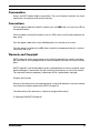
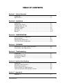
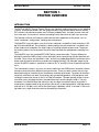
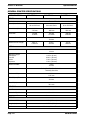
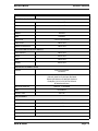
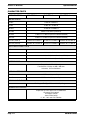
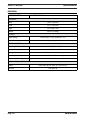
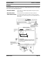
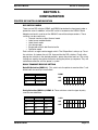
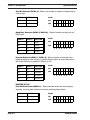
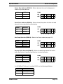
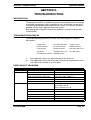
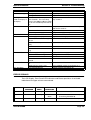
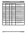
M-84PRO Thermal Transfer
Printer
Operation Manual
SATO Group of Companies
www.satoworldwide.com
SATO INTERNATIONAL PTE LTD
SATO EUROPE NV
438A Alexandra Road #05-01/ 02,
Leuvensesteenweg 369,
Alexandra Technopark,
1932 Sint-Stevens-Woluwe, Brussels,
Singapore 119967
Belgium
Tel: 65-6271-2122
Tel: 32 (0)-2-788-80-00
Fax: 65-6271-2151
Fax: 32 (0)-2-788-80-80
Email: [email protected]
Email: [email protected]
SATO UK LTD
SATO DEUTSCHLAND GMBH
Valley Road, Harwich, Essex England
Schaberweg 28, 61348
Co12 4RR, United Kingdom
Bad Homburg, Germany
Tel: 44-1255-240000
Tel: 49 (0)-6-1726-8180
Fax: 44-1255-240111
Fax: 49 (0)-6-1726-818-199
Email: [email protected]
Email: [email protected]
SATO POLSKA SP Z O.O.
SATO FRANCE S.A.
Ul Okolna 2, 50-422 Wroclaw
Parc d'activités - rue Jacques Messager
Poland
59175 TEMPLEMARS, France
Tel: 48-71-335-23-20
Tel: +33 (0)3 20 62 96 40
Fax: 48-71-335-23-25
Fax: +33 (0)3 20 62 96 55
Email: [email protected]
Email: [email protected]
SATO AMERICA INC.
SATO ASIA PACIFIC PTE LTD
10350 Nations Ford Road Suite A,
438A Alexandra Road #05-01/02,
Charlotte, NC 28273, USA
Alexandra Technopark, Singapore 119967
Tel: 1-704-644-1650
Tel: 65-6271-5300
Fax: 1-704-644-1662
Fax: 65-6273-6011
Email: [email protected]
Email: [email protected]
Warning: This equipment complies with the requirements in Part 15 of FCC rules for a Class A
computing device. Operation of this equipment in a residential area may cause unacceptable
interference to radio and television reception requiring the operator to take whatever steps
necessary to correct the interference.
All rights reserved. This document, nor any part of it, may be reproduced or issued to third
parties in any form without the express permission of SATO Europe. The material in this
document is provided for general information only and is subject to change without notice.
SATO Europe does not assume responsibility for any errors or omissions.
Warning
It is essential that the safety and operating procedures contained within this manual be
brought to the attention of, and are used by, all personnel likely to operate this printer/product.
This printer/product must only be used for the purpose for which it was designed.
This is a Class A product. In a domestic environment this product may cause radio interference in which case the user may be required to take adequate measures.
Electrostatic discharges on the connector pins and on the memory card may damage the
printer.
In the case of fire, water must not be used on the product to extinguish the fire, and the
appropriate type of fire extinguisher should be readily available.
No modifications, either mechanical or electrical, should be made to this printer/product or
accessory without the written consent of SATO Europe NV. Any modifications made without
this consent may invalidate guarantee claims.
Other manuals relating to this printer include additional information relating to other aspects
of the safe operation of the printer, and are available from your SATO supplier.
All consumable waste, such as the label backing paper and used carbon ribbon must be
disposed of carefully, and in a manner that will cause the minimum of environmental pollution.
Should you have any doubts regarding the setting, operating or any safety aspects of this
printer/product, please contact your SATO supplier.
SATO Europe NV makes no guarantee that all the features described in this manual are
available in all models, and, due to SATO’s policy of continuous development and improvement, specifications are liable to change, without notice.
SATO M-84PRO
iii
Consumables
Always use SATO carbon ribbons or equivalent. The use of incorrect materials may cause
malfunctions of the printer and void the warranty.
Conventions
Text that appears bold italic and all in capitals such as LABEL refers to a key or an LED on
the operation panel.
Text that appears enclosed in brackets such as <ESC> refers to an Escape sequence of a
data string.
Text that appears bold italic such as On-Line refers to a function or to a result.
Text that appears in bold such as VR1 refers to electrical components like pins, resistors
connectors and so on.
Warranty and Copyright
SATO Europe NV makes no guarantee of any kind with regard to this material, including,
but not limited to, the implied guaranties of merchantability and fitness for a particular purpose.
SATO Europe NV shall not be liable for errors contained herein or for any incidental consequential damages in connection with the furnishing, performance, or use of this material.
This document contains proprietary information which is protected by copyright.
All rights are reserved.
No part of this document may be reproduced or issued to third parties in any form whatsoever without the express permission of SATO Europe NV.
The information in this document is subject to change without notice.
© Copyright 2003 SATO Europe NV.
SATO M-84PRO
iv
TABLE OF CONTENTS
Section 1. Printer Overview
Introduction ................................................................................................1-1
Specifications.............................................................................................1-2
Section 2. Installation
Introduction ................................................................................................2-1
Setting Up the Printer.................................................................................2-1
Loading Labels and Tags...........................................................................2-3
Loading the Ribbon....................................................................................2-6
Operators Panel .........................................................................................2-8
Rear Panel..................................................................................................2-10
Sensors ......................................................................................................2-11
Section 3. CONFIGURATION
Printer Dip Switch Configuration................................................................3-1
Default Settings..........................................................................................3-7
Potentiometer Adjustments........................................................................3-8
LCD Panel Printer Configuration ................................................................3-10
Section 4. CLEANING
Cleaning the Print Head, Platen and Rollers ..............................................4-1
Cleaning the Label Edge Sensors ..............................................................4-2
Section 5. Troubleshooting
Introduction ................................................................................................5-1
Troubleshooting Tables..............................................................................5-1
Print Quality Problems ...............................................................................5-1
Error Signals...............................................................................................5-3
Section 6. Interface Specifications
Introduction ................................................................................................6-1
IEEE1284 Parallel Interface ........................................................................6-2
RS232 Serial Interface................................................................................6-4
Universal Serial Bus (USB) Interface ..........................................................6-6
Local Area Network (LAN) Optional Interface ............................................6-6
Section 7. Appendix A
Appendix A................................................................................................ A-1
SATO M-84PRO
v
Operation Manual
Section 1: Overview
SECTION 1.
PRINTER OVERVIEW
INTRODUCTION
The SATO M-84PRO Thermal Transfer Printers are complete, high-performance on-site labelling
systems. All printer parameters are user programmable using the front panel controls and the
DIP switches. All popular barcodes and 14 human-readable fonts, including a vector font and
two raster fonts, are resident in memory providing literally thousands of type styles and sizes.
The Operator’s Manual will help you understand the basic operations of the printer such as
setup, installation, configuration, cleaning and maintenance.
The M-84PRO can print labels up to four inches wide and is available in three resolurions; 203
dpi, 305 dpi and 609 dpi. The resolution is determined by the print head that is installed in the
printer and can be changed in the field simply by installing the desired print head. The printer
autmatically detects the resolution of the print head and loads the appropriate controlling firmware.
The M-84PRO uses the standard SATO RISC printer command codes. The only differences
between it and other RISC printers are the allowable values representing the print positions on
the label. These values are specified in “dots” and will vary depending upon the resolution of the
printer and the amount of memory available for imaging the label. The allowable range for the
various M-84PRO models is specified in a table in the “e” and PRO Printer Programming Reference.
This commonality makes it very easy to convert labels from one RISC printer to another without
having to create an entirely different command stream. There are some caveats that must be
observed though to compensate for the different resolution print heads. The effect of the different printer resolutions are best illustrated by taking a label designed for a 203 dpi printer and
sending the command stream to the its 305 dpi counterpart. The label printed will be an exact
two-thirds scale, including the fonts, barcode dimensions and line lengths/widths. The only
exception is the PostNet barcode which has only one legal size and the printer resolution is
automatically compensated for by the printer. Conversely, a label designed for a 305 dpi printer
and sent to its 203 dpi cousin will be one-third larger. It probably will be “truncated” if the resulting label size is larger than the maximum allowable for the printer.
SATO M-84PRO
Page 1-1
Section 1: Overview
Operation Manual
GENERAL PRINTER SPECIFICATIONS
SPECIFICATION
M-84PRO-2
M-84PRO-3
M-84PRO-6
PRINT
Method
Direct or Thermal Transfer
Speed (User Selectable)
2 to 10 ips
50 to 250 mm/s
2 to 8 ips
50 to 200 mm/s
2 to 6 ips
50 to 150 mm/s
Print Module (Dot Size)
.0049 in.
.125 mm
.0033 in.
.083 mm
0017 in.
.081 mm
Resolution
203 dpi
8 d/mm
305 dpi
12 d/mm
609 dpi
24 d/mm
Maximum Print Width
Maximum Print Length
4.1 in.
104 mm
49.2 in.
1249 mm
32.8 in.
835 mm
14.0 in.
356 mm
MEDIA
Minimum Width
Minimum Length
Continuous
Tear-Off
Cutter
Dispense
Maximum Width
Type
.87 in.
22 mm
0.24 in. (6 mm)
0.63 in. (16 mm)
1.18 in. (30 mm)
1.18 in. (30 mm)
5.0 in.
125 mm
Roll or Fan-Fold Die Cut Labels
Thermally Sensitive
Maximum Caliper
0.008 in.
0.21 mm
Roll OD (max) Face-In
8.6 in.
220 mm
Core ID (min)
3 in
76.2 mm
SENSING
See-Thru
Movable
Reflective Eye-Mark
Movable
Continuous Form
Sensor Not Used
RIBBON
Maximum Width
4.4 in. (111 mm)
Length (max)
1475 ft. (450 m)
Thickness
Page 1-2
4.5 micron, Wound Face-In
SATO M-84PRO
Operation Manual
SPECIFICATION
Section 1: Overview
M-84PRO All Models
CONTROLS AND INDICATORS
Power
Green LED
On-Line
Green LED
Label
Red LED
Ribbon
Red LED
Error
Red LED
LCD Panel
2 Line x 16 Character
Label Feed
Front Panel
Power On/Off Switch
Front Panel
POTENTIOMETER ADJUSTMENTS
Print Darkness
Front Panel
Offset
Front Panel
Pitch
Front Panel
Display
Front Panel
INTERFACE CONNECTIONS (1)
Parallel
Serial
Universal Serial Bus
LAN
Wireless LAN
IEEE1284 Standard
Centronics
RS232C (2,400 to 19,200 bps)
RS232C (9,600 to 57,600 bps) Standard
RS422/485 (9,600 to 57,600 bps) Optional
Ready/Busy or X-On/X-Off Flow Control
Bi-directional Status
USB Ver. 1.1 Standard
10/100BaseT
802.11b
PROCESSING
CPU
32 Bit RISC
Flash ROM
2 MB
SDRAM
16 MB
Receive Buffer
Memory Expansion
2.95 MB
See Options and Accessories
(1) Only one interface module can be installed in a printer at a time.
SATO M-84PRO
Page 1-3
Section 1: Overview
Operation Manual
CHARACTER FONTS
SPECIFICATION
M-84PRO-2
M-84PRO-3
M-84PRO-6
MATRIX FONTS
U Font
5 dots W x 9 dots H
S Font
8 dots W x 15 dots H
M Font
13 dots W x 20 dots H
XU Font
5 dots H x 9 dots H (Helvetica)
XS Font
17 dots H x 17 dots W (Univers Condensed Bold)
XM Font
24 dots H x 24 dots W (Univers Condensed Bold)
OA Font (OCR-A)
15 dots W x 22 dots H
22 dots W x 33 dots H
44 dots W x 66 dots H
OB Font (OCR-B)
30 Dots W x 36 dots H
30 Dots W x 36 dots H
60 dots W x 72 dots H
AUTO SMOOTHING FONTS
WB
18 dots W x 30 dots H
WL
28 dots H x 52 dots H
XB
48 dots H x 48 dots W (Univers Condensed Bold)
XL
48 dots W x 48 dots H (Sans Serif)
VECTOR FONT
Proportional or Fixed Spacing
Font Size 50 x 50 dots to 999 x 999 dots
Helvetica, 10 Font Variations
AGFA® RASTER FONTS
Font A
CG Times ®, 8 pt to 72 pt
Font B
CG Triumvirate®, 8 pt to 72 pt
DOWNLOADABLE FONTS
Bit Mapped TrueType® Fonts with Utility Program
CHARACTER CONTROL
Expansion to 12X in either X or Y coordinates
Character Pitch control
Line Space control
Journal Print facility
0°, 90°, 180° and 270° Rotation
Page 1-4
SATO M-84PRO
Operation Manual
Section 1: Overview
BARCODES
BARCODE
M-84PRO All Models
SYMBOLOGIES
Linear Barcodes
Bookland (UPC/EAN Supplemental)
EAN-8/EAN-13
CODABAR
CODE 39
CODE 93
CODE 128
Interleaved 2 of 5 (I 2/5)
Industrial 2 of 5
Matrix 2 of 5
MSI
POSTNET
UCC/EAN-128
UPC-A/UPC-E
Two Dimensional
Data Matrix
Maxicode
PDF417
Micro PDF
Truncated PDF
QR Code
Ratios
Bar Height
Rotation
1:2, 1:3, 2:5, User Programmable
4 to 999 dots, User Programmable
0°, 90°, 180° and 270° Rotation
OTHER FEATURES
Sequential Numbering
Custom Characters
Graphics
Forms Overlay
SATO M-84PRO
Sequential numbering of both numerics and barcodes
RAM storage for custom designed characters
Dot addressable, SATO Hex/Binary, BMP or PCX formats
Overlay of predesigned forms in image buffer
Page 1-5
Section 1: Overview
Operation Manual
PHYSICAL
SPECIFICATION
M-84PRO All Models
PHYSICAL
Wide
10.4 in. (265 mm)
Deep
17.1 in. (435 mm)
High
13.4 in.(341 mm)
Weight
39.7 lb. (18.0 Kg)
POWER
Input Voltage
Power Consumption
115/220 VAC +/-10%, 50/60 Hz +/-1%
130W Operating, 24W Idle
ENVIRONMENTAL
Operating Temperature
41° to 104°F (5° to 40°C)
Storage Temperature
23° to 140°F (-5° to 60°C)
Storage Humidity
30 to 90% RH Non-Condensing
Operating Humidity
30 to 80% RH Non-Condensing
Electrostatic Discharge
8kV
REGULATORY APPROVALS
Safety
RFI/EMI
Page 1-6
VCCI (Class B), UL, CUL, CE, FCC Class B
FCC Class B
SATO M-84PRO
Operation Manual
Section 1: Overview
OPTIONAL ACCESSORIES
ACCESSORIES AND OPTIONS
PCMCIA MEMORY
EXPANSION
One slot for PCMCIA Memory Card (up to 4 MB SRAM or 16 MB Flash
ROM). Can be used for graphic file storage, print buffer expansion, format
storage and downloaded fonts.
FLASH ROM
EXPANSION
Internal 4MB Flash ROM PCB.
REAL TIME CLOCK
An internal Date/Time clock that can be used to date/time stamp labels at
the time of printing.
LABEL DISPENSER
Internally mounted attachment allowing labels to be peeled from backing
for immediate (on demand) applications. Backing not rewound.
LABEL REWINDER
External Option that rewinds labels onto a roll after they are printed.
LABEL CUTTER
An attachment allowing labels to be cut at specified intervals. Controlled
through programming.
COAX/TWINAX
INTERFACE
Coan/Twinax Plug-In Interface module. Coax interface emmulates an IBM
3287-2 printer with a stndard Type A BNC connector. Twinax interface
emulates IBM 5224, 5225, 5226 or 4214 printers with auto-terminate/
cable through capabilities.
PARALLEL INTERFACE
IEEE1284 Bi-Directional Plug-In Interface Module
Centronics Plug-In Interface Module
SERIAL INTERFACE
High Speed RS232 Plug-In Interface Module
Slow RS232 Plug-In Interface Module
USB INTERFACE
Universal Serial Bus Plug-In Interface Module
LAN INTERFACE
10/100 BaseT Plug-In Interface Module
WIRELESS LAN
802.11b Plug-In Interface Module
All specifications subject to change without notice.
SATO M-84PRO
Page 1-7
Operation Manual
Section 2. Installation
SECTION 2.
INSTALLATION
INTRODUCTION
This section of the manual has been written to help you install the SATO M-84PRO printers and
to get started as quickly as possible. It is recommend to read each chapter in this manual before
the installation or the use of the printers.
The following information is provided in this section:
• Setting Up the Printer
• Loading Labels or Tags
• Loading the Ribbon
• Operator Panel
SETTING UP THE PRINTER
Consider the following when setting up the printer:
• Locate a solid flat surface with adequate room to set the printer. Make sure there is enough
room at the top and right-hand (facing the printer) side to provide clearance for the label
access door to swing open.
• The location should be near the host computer or terminal. The maximum distance for RS232
cables is 35 feet and six feet for IEEE1284 Parallel cables. Cables can be purchased locally,
and their configuration will depend upon the host system being used. A IEEE1284 compliant
cable must be used to realize the full throughput potential of the printers.
• For information on interfacing the printer to a host system, see Section 5: Interface
Specifications.
SATO M-84PRO
Page 2-1
Section 2. Installation
Ribbon Rewind
Spindle
Top Access
Door
Operation Manual
Ribbon Supply
Spindle
Side Access
Door
LCD
Display
DIP Switch
Cover
Power Switch
Label Hold Down
Label Roll Retainer
Label Supply Spindle
Label Guide
Print Head
Head Latch
Platen
Page 2-2
SATO M-84PRO
Operation Manual
Section 2. Installation
LOADING LABELS AND TAGS
1. Open the Top Access Door by swinging it up
and to the left. Open the Side Access Door by
swinging it to the rear of the printer.
Top Access Door
Side Access
Door
2. Open the Print Head Assembly by pushing the
Head Latch toward the rear of the printer. The
Print Head Assembly is spring-loaded and will
automatically open as soon as the Head Latch
is disengaged.
3. Loosen the Label Edge Guide and push it to
the outside of the printer to give the maximum
label width.
Label Roll Retainer
4. Remove the Label Roll Retainer
Print Head
Head Latch
Label Hold Down
Sensor Assembly
Label
Guide
Label Edge Guide
SATO M-84PRO
Page 2-3
Section 2. Installation
Operation Manual
5. If using roll labels (or tags), load the roll onto
the Label Supply Spindle so that the printing
side of the labels faces upwards as it unwinds
from the roll. The labels should be wound
face-in. Push the roll all the way to the inside
of the printer and push the Label Roll Retainer
snugly against the outside of the label roll.
6. If using fanfold labels (or tags) set them on a
flat surface behind the printer. Pass the labels
(printing side up) through the slot in the rear of
the printer.
Label Roll
7. Make sure the labels are routed under the
Label Guide and through the Sensor
Assembly.
8. Open the Label Hold-Down by squeezing the
green tab and the release tab together. The
Label Hold Down is spring loaded and will
open automatically when the latch is
disengaged. Feed the labels under the Label
Guide, under the Label Hold Down, through
the Sensor Assembly and out the front of the
printer.
Label Roll Retainer
9. Inspect the label routing and verify that the
path matches that illustrated in the Label
Loading diagram. Set the Adjustable Label
Guide to keep the labels against the inside of
the printer.
10. Close the Label Hold-Down by pushing
downward on the green tab until it latches closed.
NOTE: If the Label Dispenser option has been
purchased, see Appendix A, for proper
label routing instructions.
Print
Head
Label
Guide
Page 2-4
SATO M-84PRO
Operation Manual
Section 2. Installation
Inside Label Edge Guides
Label Hold Down
Route Labels
Under Guide
Sensor
Assembly
Sensor
Positioning
11. Adjust the outside Label Edge Guide until it
touches the outside edge of the label and
tighten the thumb screw. Make sure the
labels are also touching the inside edge
guides.
CAUTION: Using media narrower than the
maximum print width may cause excess
head wear due to the label edge. See page
2-9 for precautions.
12. If the ribbon is already loaded, close the Print
Head by rotating the black Head Latch
toward the front of the printer until it latches
closed.
Head
Latch
13. If the ribbon is not loaded, see the following description for loading instructions.
14. Close both the Access Doors.
SATO M-84PRO
Page 2-5
Section 2. Installation
Operation Manual
LOADING THE RIBBON
Ribbon Path
Ribbon Rewind
Spindle
Ribbon Roll
Head Latch
Dispensed
Label
Label Backing
Sensor
Assembly
Label Hold
Down
1. Open the Top Access Door by
swinging it up and to the left and the
Side Access Door by swinging it
toward the rear of the printer.
Label Path
Top Access Door
Side Access Door
2. Open the Print Head by rotating the
Head Latch toward the rear of the
printer. The Print Head is spring-loaded
and will automatically open as soon as
the Head Latch is disengaged.
3. Locate the extra ribbon core supplied
with the printer. Place the core on the
Ribbon Rewind Spindle, pushing it all
the way to the inside of the spindle.
Note that the new empty core of each
subsequent roll becomes the next rewind core.
4. Load the ribbon onto the Ribbon Supply Spindle, also pushing it all the way to the inside of
the spindle. The dull side of the ribbon should be facing down as it travels through the Print
Head Assembly.
5. Feed the leader portion of the ribbon through the Print Head Assembly and up to the Ribbon
Rewind Spindle following the routing shown in the diagram.
6. Load the ribbon behind and over the top of the Ribbon Rewind Spindle and tape it to the
Extra Ribbon Core. Make sure it matches the ribbon path shown in the diagram.
7. Manually turn the Rewind Spindle to wrap the ribbon onto the core one to two turns to
secure it.
Page 2-6
SATO M-84PRO
Operation Manual
Section 2. Installation
8. If the labels or tags are already loaded,
close the Print Head Assembly by
pushing downward on the green tab
until it latches closed.
9. Run a test print to ensure that the
labels and ribbons were loaded
correctly.
Tape
Ribbon
Core
CAUTION: If your labels are less than the full width of the print head, the outside edge will
eventually wear out a small portion of the print head, resulting in an area that will not
print. Special care must be taken if you plan to use multiple widths of labels, since the
damaged portion of the print head caused from edge wear on a more narrow label may
affect the printing on a wider label. We suggest you plan your print formats carefully to
avoid using the area of possible damage on the print head when using a wider label. The
small area of damage will have no effect on printing with the undamaged part of the print
head. Damage from a label edge is physical damage and is unavoidable. It is not covered
by warranty. It is possible to delay such damage by always ensuring that the ribbon used
is wider than the label stock. This will help to protect the print head from label edge
damage.
SATO M-84PRO
Page 2-7
Section 2. Installation
Operation Manual
OPERATOR PANEL
The M-84PRO Operator Panel consists of five LED indicators, two momentary contact switches, three
DIP switches, four adjustment potentiometers and one LCD Display. All of these are accessible from the
front of the printer. They are used to set the printer operating parameters and to indicate the status of the
printer to the operator. After you power on the printer, familiarize yourself with the keys and indicators as it
will help you understand the configuration process.
PRINT
Potentiometer to adjust print darkness (fine tuning)
OFFSET
Potentiometer to adjust amount of back/forward feed for dispenser/cutter/
tear-off position (+/- 3.75 mm)
PITCH
Potentiometer to adjust home position of the label (+/- 3.75 mm). Affects stop
position of label feed, print position and dispense position.
DISPLAY
Potentiometer to adjust the contrast of the LCD display.
POWER
LED, illuminated when the power is on.
LABEL
LED, illuminated when the label supply is not detected.
RIBBON
LED, illuminated when the ribbon motion sensor does not detect any ribbon
motion (ribbout out condition).
ERROR
LED, illuminated when there is a system fault such as an open print head.
Page 2-8
SATO M-84PRO
Operation Manual
Section 2. Installation
ON LINE
LED, illuminated when printer is ready to receive data. Toggled on/off with
LINE key.
LINE
Momentary switch. Pressing this key toggles the printer between the online and off-line mode. When the printer is on-line, it is ready to receive data
from the host. This key acts as a pause during a print job by taking the printer
off-line. It can also be used as a Pause function key to stop the printer during
the printing process.
FEED
Momentary switch. Pressing this key feeds one blank label when the printer is
Off-Line. When the printer is On-Line, another copy of the last label will be
printed (Reprint W/Feed must be enabled in the LCD panel Service Mode).
DSW
DIP switch array to set operational parameters of the printer.
LCD
2 Line x 16 Character LCD display. Used for setting operational parameters of
the printer and displaying error conditions.
SATO M-84PRO
Page 2-9
Section 2. Installation
Operation Manual
REAR PANEL
AC INPUT
Input 115V/240V, 50/60 Hz connector. Use cable provided.
AC FUSE
Input power protection. 3A/250V rating.
INTERFACE SLOT
Connector for Plug-In Interface Module.
MEMORY CARD SLOT
Connector for optional PCMCIA Memory Card.
EXT
External signal connector, AMP 57-60140.
Plug-In Interface
Module
Fan-Fold
Access Panel
EXT Port
Connector
PCMCIA
Card Cover
Fuse
AC Connector
Page 2-10
SATO M-84PRO
Operation Manual
Section 2. Installation
SENSORS
The M-84PRO printers contain three sensing units; a Ribbon End motion sensor, a Head Open
micro-switch and a Label Indexing Sensor.
RIBBON END SENSOR
Detect motion of the Ribbon Supply Spindle and signals the printer
when it is turning.
HEAD OPEN SENSOR
A micro-switch that is activated when the head is unlatched.
LABEL INDEXING SENSOR
The sensing assembly contains two types of sensors, one for label
gap and one for eye-mark sensing. The sensors are adjustable over a
limited range.
Label Gap Sensor
Reflective Sensor
Eye-Mark on
bottom of
liner.
14 mm
min
Reflective
7 mm to 54 mm
Label Gap
Maximum number of
print head dots is
dependent upon the
model.
SATO M-84PRO
The range of sensor adjustment can be increased to allow
the Gap sensor to be positioned as close as 3 mm from the
inside label edge. Contact SATO for information on how to
make this modification.
Page 2-11
Operation Manual
Section 3. Configuration
SECTION 3.
CONFIGURATION
PRINTER DIP SWITCH CONFIGURATION
DIP SWITCH PANELS
There are two DIP switches (DSW2 and DSW3) located on the front panel under a
protective cover. In addition, a third DIP switch is located on the RS232C Serial
Adapter card and is used to set the RS232C transmit/receive parameters. These
switches can be used to set:
• Thermal transfer or direct thermal mode
• Label sensor enable/disable
• Head check mode
• Hex dump mode
• Single Job or Multi-Job Receive buffer
• Operation mode
Each switch is an eight section toggle switch. The ON position is always up. To set
the switches, first power the unit Off, then position the DIP switches. Finally, after
placing the switches in the desired positions, power the printer back on. The switch
settings are read by the printer electronics during the power up sequence. They will
not become effective until the power is cycled.
RS232 TRANSMIT/RECEIVE SETTING
Data Bit Selection (DSW1-1). This switch sets the printer to receive either 7 or 8
bit data bits for each byte transmitted.
DSW1-1
SETTING
DSW1
Off
8 Data Bits
ON
On
7 Data Bits
OFF
1
2
3
4
5
6
7
8
Parity Selection (DSW1-2, DSW1-3. These switches select the type of parity
used for error detection.
DSW1-1
DSW1-3
SETTING
DSW1
Off
Off
No Parity
ON
Off
On
Even
OFF
On
Off
Odd
On
On
Not Used
SATO M-84PRO
1
2
3
4
5
6
7
8
Page 3-1
Section 3. Configuration
Operation Manual
Stop Bit Selection (DSW1-4). . Selects the number of stop bits to end each byte
transmission.
DSW1-4
SETTING
DSW1
Off
1 Stop Bit
ON
On
2 Stop Bits
OFF
1
2
3
4
5
6
7
8
Baud Rate Selection (DSW1-5, DSW1-6). . Selects the data rate (bps) for the
RS232 port.
DSW1-5
DSW1-6
SETTING
DSW1
Off
Off
9600
ON
Off
On
19200
OFF
On
Off
38400
On
On
57600
1
2
3
4
5
6
7
8
Protocol Selection (DSW1-7, DSW1-8). Selects the flow control and status
reporting protocols. See Section 6: Interface Specifications for more information. (*
Will select the Status 2 protocol if DSW2-8 is ON).
DSW1-7
DSW1-8
SETTING
DSW1
Off
Off
Rdy/Bsy
ON
Off
On
Xon/Xoff
OFF
On
Off
Bi-Com 3
On
On
Bi-Com 4
1
2
3
4
5
6
7
8
PRINTER SET UP
Print Mode Selection (DSW2-1). . Selects between direct thermal printing on
thermally sensitive paper and thermal transfer printing using a ribbon.
DSW2-1
SETTING
DSW2
Off
Therm Xfr
ON
On
Direct Therm
OFF
1
Page 3-2
2
3
4
5
6
7
8
SATO M-84PRO
Operation Manual
Section 3. Configuration
Sensor Type Selection (DSW2-2). Selects between the use of a label gap or a
reflective Eye-Mark detector.
DSW2-2
SETTING
DSW2
Off
Gap
ON
On
Eye-Mark
OFF
1
2
3
4
5
6
7
8
Head Check Selection (DSW2-3). When selected, the printer will check for head
elements that are electrically malfunctioning.
DSW2-3
SETTING
DSW2
Off
Disabled
ON
On
Enabled
OFF
1
2
3
4
5
6
7
8
Hex Dump Selection (DSW2-4). Selects Hex Dump mode (see page 3-21).
DSW2-4
SETTING
DSW2
Off
Disabled
ON
On
Enabled
OFF
1
2
3
4
5
6
7
8
Receive Buffer Selection(DSW2-5). Selects the operating mode of the receive
buffer. See Section 6.Interface Specifications for more information.
DSW2-5
SETTING
DSW2
Off
Single Job
ON
On
Multi Job
OFF
1
2
3
4
5
6
7
8
If a 10/100BaseT LAN card is installed, DS2-5 has the following definitions:
DSW2-5
SETTING
Off
ENQ Response
On
Periodic Response
SATO M-84PRO
Page 3-3
Section 3. Configuration
Operation Manual
Firmware Download (DSW2-6). Places the printer in the Firmware Download mode
for downloading new firmware into flash ROM.
DSW2-6
SETTING
DSW2
Off
Disabled
ON
On
Enabled
OFF
1
2
3
4
5
6
7
8
Protocol Code Selection (DSW2-7). Selects the command codes used for
protocol control. Refer to page E-1 for more information.
DSW2-7
SETTING
DSW2
Off
Standard
ON
On
Non-Std
OFF
1
2
3
4
5
6
7
8
Status Select(DSW2-8). For emulating earlier series software commands. Should
be used only if problems are encountered when using existing software. This switch
will also affect the settings selected by DSW1-7 and DSW1-8.
DSW2-8
SETTING
DSW2
Off
Status 3 & 4 Enabled
ON
On
Status 2 & 3 Enabled
OFF
1
2
3
4
5
6
7
8
Backfeed Sequence (DSW3-1, DSW3-2). Backfeed is used to correctly position
the label for application and then retract the next label to the proper print position.
This operation can be performed immediately after a label is printed and used, or
immediately prior to the printing of the next label.
DSW3-1
SETTING
DSW3
Off
Off
Continuous
ON
Off
On
Tear-Off
OFF
On
Off
Cutter*
On
On
Not Used
1
2
3
4
5
6
7
8
* Defaults to Continuous if cutter not
installed
Page 3-4
SATO M-84PRO
Operation Manual
Section 3. Configuration
Label Sensor Selection (DSW3-3). Enables or disables the Label Sensor. If the
Sensor is enabled, it will detect the edge of the label and position it automatically. If it
is disabled, the positioning must be under software control using Line Feed
commands.
DSW3-3
SETTING
DSW3
Off
Not Used
ON
On
Sensor Used
OFF
1
2
3
4
5
6
7
8
Back-Feed Selection (DSW3-4). When Back-Feed is enabled, the printer will
position the last printed label for dispensing and retract it before printing the next
label. The amount of backfeed offset is adjustable.
DSW3-4
SETTING
DSW3
Off
Disabled
ON
On
Enabled
OFF
1
2
3
4
5
6
7
8
External Signal Interface. See Section 6: Interface Specifications for information
on the External Signals.
EXT Print Start Signal Selection (DSW3-5). Allows an external device to initiate a
label print for synchronization with the applicator. When DSW3-5 is On, the unit is in
the Continuous print mode, Backfeed is disabled and External Signals are ignored.
DSW3-5
SETTING
DSW3
Off
Enabled
ON
On
Disabled
OFF
1
SATO M-84PRO
2
3
4
5
6
7
8
Page 3-5
Section 3. Configuration
Operation Manual
External Signal Type Selection (DSW3-6, DSW3-7). Both the polarity and signal
type (level or pulse) of the external print synchronizing signal can be selected.
DSW3-6
DSW3-7
SETTING
DSW1
Off
Off
Type 4
ON
Off
On
Type 3
OFF
On
Off
Type 2
On
On
Type 1
1
2
3
4
5
6
7
8
Repeat Print via External Signal (DSW3-8). Allows the applicator to reprint the
current label in the print buffer.
DSW3-8
SETTING
DSW3
Off
Enabled
ON
On
Disabled
OFF
1
Page 3-6
2
3
4
5
6
7
8
SATO M-84PRO
Operation Manual
Section 3. Configuration
DEFAULT SETTINGS
SWITCH SELECTIONS
All switches are placed in the Off default position for shipping. This will result in the
following operating configuration:
Communications:
Protocol:
Sensor:
Receive Buffer:
Mode:
Label Sensor:
Backfeed:
External Signals:
8 data bits, no parity, 1 Stop bit, 9600 Baud
Ready/Busy
Gap Sensor
Multi Job
Batch/continuous
Sensor Used
Enabled
Enabled
SOFTWARE DEFAULT SETTINGS
The printer stores the software settings upon receipt and uses them until they are
again changed by receipt of a command containing a new setting. These settings are
stored in non-volatile memory and are not affected by powering the printer off. The
printer may be reset to use the default software settings by depressing the LINE and
FEED keys simultaneously while powering the printer on. This will result in the
following default configuration:
Print Darkness
Print Speed
Print Reference
Zero
Print Offset
Ignore CR/LF
Character Pitch
Ignore CAN/DLE
Auto On Line
Feed on Error
Feed Reprint
Priority
Language
CC1 Mem Select
Eurocode
M-84PRO
3
6 ips (3 ips for M-84PRO-6)
Vertical = 0000, Horizontal = 0000
No Slash
+0
Disabled
Proportional
Disabled
Enabled
Enabled
Disabled
Command
English
Card
D5H
Once the default operation is completed, a DEFAULT COMPLETED message will be
displayed on the LCD panel. The printer should be powered off while this message is being
displayed (or after the beep is heard. This saves the default settings in the non-volatile
memory where they will be automatically loaded the next time the printer is powered on.
DEFAULT COMPLETED
SATO M-84PRO
Page 3-7
Section 3. Configuration
Operation Manual
POTENTIOMETER ADJUSTMENTS
PITCH
After the pitch has been set with the LCD Control Panel, it is sometimes desirable to
make minor adjustments. This can be done using the PITCH potentiometer on the
top panel. This potentiometer is set at the factory so that it has a range of +/- 3.75
mm. The midpoint setting should have no effect on the pitch. Turning the
potentiometer all the way clockwise should move the print position 3.75 mm up
towards the top edge of the label. Turning it all the way counterclockwise should
move the print position down 3.75 mm.
1. While depressing the FEED key on the front panel, power the printer on.
2. When you hear one beep from the printer, release the FEED key and the printer
will display on the LCD panel a message asking what type of Test Label you want
to print.
3. Use the Cursor keys to step to the Configuration selection and press the ENTER
key to accept the selection.
4. Use the Cursor keys to select the Test Label Size. After the size is selected, press
the ENTER key to accept the selection and the printer will begin to print test
labels continuously.
5. Adjust the PITCH potentiometer on the front panel until the first print position is
at the desired location on the label. If the potentiometer does not have enough
range, then you will have to change the pitch setting using the front panel display.
6. Press the FEED key to stop the printer.
7. To exit the Test Label mode, power the printer off and then back on.
Adjusting the PITCH potentiometer will affect the stop position of the label.
BACKFEED OFFSET
When a label is printed it must be correctly positioned for dispensing and
application. The Backfeed adjustment is used to position the label so that it is fully
dispensed and ready for application. It may then be necessary to reposition the next
label before printing. The Backfeed (repositioning of the label) operation is enabled if
DSW3-4 is in the Off position. If Backfeed is enabled, placing DSW3-1 is in the Off
position will cause the backfeed operation to be performed immediately before each
label is printed. If DSW3-1 is in the On position, the backfeed operation is performed
as soon as the dispensed label has been printed and taken from the printer.
The amount of backfeed is controlled by the OFFSET potentiometer on the DIP
Switch Panel inside the cover. When turned all the way counterclockwise, the
amount of backfeed is +3.75 mm, and -3.75 mm when turned all the way
counterclockwise.
1. Turn the printer on.
2. Press the LINE key to place the printer in the Off Line status.
3. Press the FEED key to feed out a blank label.
Page 3-8
SATO M-84PRO
Operation Manual
Section 3. Configuration
4. Adjust the position using the OFFSET potentiometer on the front control panel
and feed another label by depressing the FEED key. Repeat this procedure until
the label is fully released from the liner.
DISPLAY
This potentiometer is used to adjust the contrast of the LCD display for optimum
viewing under various lighting conditions.
PRINT
The PRINT potentiometer is used to adjust the amount of heat (i.e., power) applied to
the head for printing. It provides a continuous range of adjustment. Maximum print
darkness is obtained by turning the potentiometer all the way clockwise and a
maximum counterclockwise setting will give the lightest print.
NOTE: The PRINT potentiometer adjustment will affect the darkness in all of the
command code speed and darkness ranges.
SATO M-84PRO
Page 3-9
Section 3. Configuration
Operation Manual
LCD PANEL PRINTER CONFIGURATION
The LCD Panel is used by the operator in conjunction with the LINE and FEED
switches to manually enter printer configuration settings. Many of these settings can
also be controlled via software commands and in the case of conflict between
software and control panel settings, the printer will always use the last valid setting. If
you load a label job that includes software settings and then enter a new setting via
the LCD panel, the manually set values will be used by the printer. If you set the
values manually and then download a job with software settings, the software
settings will be used.
NORMAL MODE
The printer initially powers on in the ONLINE mode. The user can access the User
Settings using the following procedures.
V 05.00.03.00
INITIALIZING
Displays the firmware during the initialization.
ONLINE
QTY:000000
The LCD will display the ONLINE status on the top line and the
bottom line will contain the label quantity (QTY) status. The
messsge will be changed to OFFLINE whenever the printer is
switched offline by pressing the LINE key. As soon a print job is
received, the quantily line will indicate the number of labels to
be printed. As soon as the label job begins to print, the display
will indicate the number of labels in the print job that remains to
be printed.
OFFLINE
Press the LINE key once. When the display changes to
OFFLINE, press the FEED and LINE keys simultaneously for
more than one second. Release the keys.
000000
PRINT DARKNESS
1
2
3
4
5
The LCD now displays the Print Darkness selections. The
current setting is indicated by a cursor over one of the range
settings. There are 5 possible selections. The lowest setting
represents the lightest print and the highest setting the darkest
print.
1. Press the Cursor keys to step the cursor to the desired
setting.
2. Once the correct setting is underlined, press the ENTER
key to accept the selection and step the display to the next
adjustment.
PRINT SPEED
2
4
6
8
10
The print speed selections are dependent upon the printer
model. The current setting is indicated by the cursor.
1. Use the Cursor keys to step the cursor to the desired
setting.
2. Once the correct setting is selected, press the ENTER key
to accept the selection and step the display to the next
adjustment.
Page 3-10
SATO M-84PRO
Operation Manual
PITCH OFFSET
+ 00mm
Section 3. Configuration
The label Pitch is the distance from the leading edge (the edge
that comes out of the printer first) of a label and the leading
edge of the next label. The leading edge position of the label
can be adjusted relative to the print head +/- 49mm in
increments of 1mm. Once the position is set, it can be fine
adjusted +/- 3.75mm using the PITCH potentometer on the
Adjustment Panel.
1. The cursor will initially be positioned over the Pitch
Direction setting. Use the LINE key to step to the positive
(+) or negative (-) selection. A positive selection moves the
leading edge of the label forward (away from the print head)
while a negative selection moves the leading edge of the
label back into the mechanism.
2. Once the correct direction is selected, pressing the LINE
key will accept the setting and advance the cursor to the
Offset selection.
3. Use the LINE key to step the first digit of the counter to the
desired setting. The display will increment one step each
time the Cursor keys are pressed. The maximum setting is
4.
4. Press the FEED key to accept the setting and advance the
cursor to the second digit. Again use the LINE key to step
to the desired setting. Once it is correct, pressing the FEED
key will step to the next adjustment.
5. You may wish to print a test label after completing the
adjustments to ensure they are correct.
SATO M-84PRO
Page 3-11
Section 3. Configuration
CANCEL PRINT JOB
YES
NO
Operation Manual
If the printer has a print job(s) in memory, selecting YES will
cause the job(s) to be cleared. The default selection is NO. Be
sure you want to cancel the print job(s) before selecting yes as
the job(s) cannot be recovered and will have to be retransmitted
to the printer.
1. Use the Cursor keys to step the cursor to either the YES or
NO selection.
2. Once the correct setting is selected, pressing the ENTER
key will accept the setting.
CANCEL PRINT JOB
COMPLETED
3. After the print job(s) have been cleared from memory, the
printer will beep 3 times and display a COMPLETED
message for 3 seconds and then return to the initial
ONLINE Normal Mode.
4. If you wish to change any of the settings, you must enter
the User Settings mode again by taking the printer
OFFLINE and pressing the LINE and FEED keys.
Page 3-12
SATO M-84PRO
Operation Manual
Section 4. Cleaning and Maintenance
SECTION 4.
CLEANING
CLEANING THE PRINT HEAD, PLATEN AND ROLLERS
Supplies needed:
SATO SA070 Cleaning Kit
Cleaning the Print Head
1. Turn the printer off and remove
the power cable.
2. Open the Top and Side Access
Door.
3. Open the Print Head Assembly by
rotating the Head Latch toward
the back of the printer. The Print
Head Assembly is spring-loaded
and will automatically open as
soon as the Head Latch is
disengaged.
Head Cleaning
TBA
4. Remove the ribbon.
5. Apply SATO Thermal Print Head
Cleaner to a cotton swab.
6. The Print Head faces downward along the front edge of the assembly. Pass the
end of the dampened swab along the epoxy ridge that runs the entire width of the
Print Head.
7. Check for any black colouring or adhesive on the swab after cleaning.
8. Repeat if necessary until the swab is clean after it is passed over the head.
9. The head should be cleaned at least every time the ribbon is changed and more
often in dusty environments.
Cleaning the Platen and Rollers
1. Turn the printer off and remove the
power cable.
2. Open Top and Side Access doors.
3. Open the Print Head Assembly by
rotating the Head Latch toward the
rear of the printer. The Print Head
Assembly is spring-loaded and will
automatically open as soon as the
Head Latch is disengaged.
4. Unlatch the Label Hold-Down by
lifting up on the latch lever
(immediately below the green PUSH tab.
5. Apply SATO Thermal Print Head Cleaner to one of the cotton swabs.
SATO M-84PRO
Page 4-1
Section 4. Cleaning and Maintenance
Operation Manual
6. The Platen is the rubber roller directly below the Print Head. It should be cleaned
of any ribbon or label residue.
7. A pair of Label Feed Rollers are used to assist in label feeding at high print
speeds. One located in the bottom of the Label Hold-Down and the other directly
underneath it in the label feed path. They should be cleaned of any label residue
or foreign material.
8. Repeat if necessary. The platen and rollers should be cleaned whenever foreign
matter such as dust or adhesive is present.
9. Close the Label Hold-Down until it latches in place.
10. Close the Print Head by rotating the Head Latch Lever down and towards the
front until it latches in place.
CLEANING THE LABEL EDGE SENSORS
There are two sensors that are used to control the positioning of the label. One is a
transmissive see-thru sensor that detects the edge of the label by looking through
the backing paper which is translucent and detecting the presence of the opaque
backing. The other is a reflective sensor that detects the light reflected from the
bottom of the label liner. When a printed black Eye-Mark passes through the beam,
the light is no longer reflected back to the sensor detector, indicating to the printer
that it should use this position as the start of a new label. When dust, dirt or other
foreign matter interferes with the light path of either of these sensors, the results is
erratic label positioning. These sensors should be cleaned regularly, at least every
two rolls of labels. They are both located on an adjustable assembly in the throat of
the printer between the Label Hold Down and the Print Head.
Supplies Needed:
SATO Cleaning Kit
1. Turn the printer off and remove the power cable.
2. Open the Top and Side Access doors.
3. Open the Print Head by pushing the Head Latch toward the rear of the printer.
The Print Head is spring-loaded and will automatically open as the Head Latch is
disengaged.
4. Remove the ribbon.
5. Apply SATO Thermal Print Head Cleaner to a cotton swab.
6. Carefully insert the swab between the top and bottom portions of the Sensor
Assembly. The location of the sensors is identified by two marks on the
assembly.
7. Move the swab back and forth to clean any residue from the sensors.
Page 4-2
SATO M-84PRO
Section 5. Troubleshooting
Operation Manual
SECTION 5.
TROUBLESHOOTING
INTRODUCTION
The design of the SATO CL-608e/612e printer is based upon proven technology
and reliable components. When a problem occurs, the solution can be easily
traced using the troubleshooting tables in this section. This table list symptoms,
probable causes, and suggested corrective actions.
Both print quality and general operational problems are listed in the troubleshooting table.
TROUBLESHOOTING TABLES
The troubleshooting table below includes the following general symptom
descriptions:
• Image Voids
• No Label Movement • LABEL LED on
• Ribbon Wrinkle
• No printed Image
• RIBBON LED on
• Light Images
• Display Problem
• ON LINE LED not on
• Smearing
• POWER LED not on • No Label Drive
• No Ribbon Movement • ERROR LED on
☺
#
The suggested actions may be carried out by the end-user.
The suggested actions should only be carried out by experienced service
staff. Recall your reseller or service agent.
PRINT QUALITY PROBLEMS
SYMPTOM
Image Voids
Ribbon Wrinkle
SATO M-84PRO
PROBABLE CAUSE
SUGGESTED CORRECTIVE ACTION
Poor quality labels
Use thermal transfer compatible stock ☺
Poor quality ribbons
Use genuine SATO ribbons ☺
Ribbon not matched to label stock
Check with media suppliers ☺
Damaged electronics
Replace circuit board #
Damaged Platen
Replace Platen #
Poor Head Alignment
Adjust head balance #
Adjust ribbon roller #
Adjust head alignment #
Poor Ribbon Tension
Adjust ribbon tension #
Worn Platen
Replace platen #
Foreign material on head or platen
Clean head and platen ☺
Foreign materials on labels
Use high quality label stock ☺
Damaged print head
Replace print head #
Page 5-1
Section 5. Troubleshooting
Operation Manual
SYMPTOM
PROBABLE CAUSE
SUGGESTED CORRECTIVE ACTION
Light Images
Poor quality labels
Use thermal transfer compatible stock ☺
Poor quality ribbons
Use genuine SATO ribbons ☺
Low print head energy/darkness
Adjust darkness control ☺
Low print head pressure
Use correct head pressure position #
Ribbon not matched to label stock
Select better suited carbon Ribbon ☺
Foreign material on head
Clean head and platen ☺
Poor head alignment
Align Print Head #
Excessive print speed
Reduce print speed setting ☺
Poor quality labels
Select better suited carbon Ribbon ☺
Poor quality ribbons
Use genuine SATO ribbons ☺
Foreign material on head/platen
Clean head and platen ☺
Foreign material on labels
Use high quality label stock ☺
Excessive print head energy
Adjust darkness control ☺
Excessive print speed
Adjust print speed ☺
Excessive head pressure
Use correct head pressure position #
Incorrect ribbon core size
Use genuine SATO ribbons ☺
Loose platen drive belt
Adjust/replace belt #
No + 24 volt output
Test power supply and replace if required #
Smearing
No Ribbon
Movement
Loose service screws on rewind pulley Tighten service screws #
Damaged electronics
No Label Move- Loose/broken platen drive belt
ment
Incorrect label pitch sensor selected
No +24 volt output
Replace circuit board #
Adjust/replace belt #
Select correct label sensor type (DSW2-2) ☺
Replace fuse on main PCB #
Test power supply and replace if required #
Loose set screw on platen pulley/step- Tighten set screws #
per motor
No Printed
Image
Page 5-2
Print head not connected
Verify print head connector fully seated at
head and PCB #
Ribbon upside down
Use genuine SATO ribbons ☺
No + 24 volt output
Test power supply and replace if required #
SATO M-84PRO
Operation Manual
SYMPTOM
Section 5. Troubleshooting
PROBABLE CAUSE
SUGGESTED CORRECTIVE ACTION
No Printed Image
Damaged print head
Damaged electronics
Back light but no
Most common failure of printer is
words on display or DOA situation. The most likely
no display.
cause is the ribbon cable has fallen
out or not seated fully into connector.
POWER LED not on AC power cable not connected
Main Power Fuse defective
Defective power supply
ERROR LED on
Head not locked
LABEL LED on
Label supply roll empty
Label stock not routed through
sensor
Label sensor not positioned correctly
Label sensor blocked
Incorrect label sense threshold setting
RIBBON LED on
Ribbon supply roll empty
Ribbon sensor out of alignment
Ribbon sensor blocked
No cardboard core on ribbon
rewind
ON LINE LED not on LABEL, RIBBON, ERROR LED (s)
on
Illegal printer memory state
No Label Drive
Timing Belt bad/loose
Replace print head #
Replace circuit board #
Verify that the cable and connector are properly seated ☺
Verify that the cable is connected to the printer
and the AC outlet ☺
Replace fuse #
Test power supply and replace if defective #
Close and latch head release ☺
Replenish label supply ☺
Reload labels ☺
Adjust sensor position #
Clean label sensor ☺
Adjust label sense threshold #
Replenish ribbon supply ☺
Realign ribbon sensor #
Clean ribbon sensor #
Use cardboard core on ribbon rewind ☺
Clear error condition ☺
Cycle POWER switch off and back on ☺
Replace/tighten timing belts #
ERROR SIGNALS
The LCD Display, Front Panel LED Indicators and Buzzer provide a visual/audio
indication of the type of error encountered.
LED
LCD
MESSAGE
AUDIBLE
BEEP
ERROR
CONDITION
Error On
Machine Error
1 Long
Machine Error
Error On
EEPROM Error
1 Long
Error On
Head Error
1 Long
SATO M-84PRO
POSSIBLE CAUSES
1. Defective Board #
EEPROM Read/ 1. EEPROM not installed correctly #
Write
2. Overwriting EEPROM #
Head
1. Electrical head malfunction #
Page 5-3
Section 5. Troubleshooting
Operation Manual
LED
LCD
MESSAGE
AUDIBLE
BEEP
ERROR
CONDITION
Error On
Sensor Error
3 Short
Sensor
Error Blinks
Card R/W Error
1 Long
Memory Card
Read/Write
1. Card not formatted #
1. No card recognized #
Error Blinks
Card Low
Battery
1 Long
Memory Card
Battery Low
1. Card battery needs replacement#
Error Blinks
Card No Battery
1 Long
No Battery in
Card
1. Card needs battery installed #
Error Blinks
Head Open
3 Short
Head Open
Error Blinks
Cutter Error
3 Short
Cutter
Error On
Line Blinks
Parity Error
3 Short
RS232 Parity
Error
1. RS232 parameter mismatch #
Error On
Line Blinks
Overrun Error
3 Short
RS232 Overrun
Error
1. RS232 parameter mismatch #
Error On
Line Blinks
Framing Error
3 Short
RS232 Framing
Error
1. RS232 parameter mismatch #
Error On
Line Blinks
Buffer Over
3 Short
Buffer Overflow 1. Command stream exceeds buffer
size #
Error Blinks
Paper End
3 Short
Media End
1. No paper ☺
2. Paper incorrectly loaded ☺
Error Blinks
Ribbon End
3 Short
Ribbon End
1. Needs new ribbon roll ☺
2. Ribbon sensor needs adustment#
Download Error
R/W Error
Mem Full Error
3 Short
CopyCard/
Format
R/W Error
No Card Error
Mem Full Error
3 Short
Page 5-4
POSSIBLE CAUSES
1. Paper jam ☺
2. Sensor DSW setting #
3. Sensor level adjustment #
1. Head not latched ☺
2. Head latch switch bad #
1. Cutter jam #
2. Cutter sensor dirty #
Download Error 1. Read/Write error #
2. Corrupted download file #
3. Download file too large #
Card Copy or
Format Error
1. R/W error during copying. #
2. Card not installed properly. #
3. File too large. #
SATO M-84PRO
Operation Manual
Section 6. Troubleshooting
SECTION 6.
INTERFACE SPECIFICATIONS
INTRODUCTION
The M-84PRO printer utilize a Plug-In Interface Module for maximum printer
configuration flexibility. This section presents the interface specifications for the M84PRO printers. These specifications include detailed information on how to properly
interface your printer with your host system.
The following information is presented in this section:
• Using the Receive Buffer
• IEEE1284 Parallel Interface
• Universal Serial Bus (USB) Interface
• Local Area Network (LAN) Interface
• RS232C Serial Interface
• Bi-Comm Communications Protocol
• Status Response
WARNING: Never connect or disconnect interface cables (or use a switch box) with power
applied to either the host or the printer. This may cause damage to the interface
circuitry in the printer/host and is not covered by warranty.
SATO M-84PRO
Page 6-1
Section 6. Troubleshooting
Operation Manual
IEEE1284 PARALLEL INTERFACE
The parallel interface for the M-84PRO printers is a Plug-In Interface Module that can
be installed by the user. It conforms to the IEEE1284 specification. It will
automatically detect the IEEE1284 signals and operate in the high speed mode. If it
does not detect the IEEE1284 signals, it will operate in the standard Centronics
mode, which is significantly slower. For this reason, an interface cable and host
interface conforming to the IEEE1284 specification must be present to fully utilize the
speed capabilities. This interface also operates bi-directionally and can report the
status of the printer back to the host.
ELECTRICAL SPECIFICATIONS
Page 6-2
Printer Connector
AMP 57-40360 (DDK) or equivalent
Cable Connector
AMP 57-30360 (DDK) or equivalent
Cable
IEEE1284 Parallel, 10 ft. (3 m) or less
Signal Level
High = +2.4V to +5.0V
Low = 0V to -0.4V
SATO M-84PRO
Operation Manual
Section 6. Troubleshooting
DATA STREAMS
<ESC>A . . Job#1 . . <ESC>Z<ESC>A . . Job#n . . <ESC>Z
SATO M-84PRO
Page 6-3
Section 6. Troubleshooting
Operation Manual
RS232 SERIAL INTERFACE
The High Speed Serial Interface is a Plug-In Interface Module that can be installed in
the printer by the user.
GENERAL SPECIFICATIONS
Asynchronous ASCII
Half-duplex communication
Ready/Busy Hardware Flow Control
Pin 20, DTR Control
Pin 4, RTS Error Condition
X-On/X-Off Software Flow Control
Bi-Directional Communication
Data Transmission Rate
9600, 19200, 38400, 57600 bps
Character Format
1 Start Bit (fixed)
7 or 8 data bits (selectable)
Odd, Even or No Parity (selectable)
1 or 2 Stop bits (selectable)
ELECTRICAL SPECIFICATIONS
Connector DB-25S (Female)
Cable
DB-25P (Male), 50 ft. maximum length.
For cable configuration, refer to Cable
Requirements appropriate to the RS232C
protocol chosen.
Signal Levels
High = +5V to +12V
Low = -5V to -12V
PIN ASSIGNMENTS
Page 6-4
SATO M-84PRO
Operation Manual
Section 6. Troubleshooting
CABLE REQUIREMENTS
SATO M-84PRO
Page 6-5
Section 6. Troubleshooting
Operation Manual
UNIVERSAL SERIAL BUS (USB) INTERFACE
The Universal Serial Bus (USB) interface is a Plug-In Interface Module that can be
installed by the user. It requires a driver (shipped with each printer that has the
interface installed) that must be loaded on your PC and the PC must be configured to
support USB peripherals using Windows 98 or above. Details for loading the USB
driver are contained in the USB Interface Manual that is shipped with each printer
with a USB Optional interface installed. Up to 127 devices may be connected to a
USB port using powered hubs.
GENERAL SPECIFICATIONS
Connector:
USB Type B Plug
Cable:
10 ft (3 m) max
Host:
Windows 98 or above with USB Port
ELECTRICAL SPECIFICATIONS
Power Supply:
BUS Power through cable
Power Consumption:
+5V@80ma
LOCAL AREA NETWORK (LAN) INTERFACE
A Local Area Network (LAN) interface is a Plug-In Interface Module that can be
installed by the user. It requires a driver shipped with each printer that has the
interface installed. The driver that must be loaded on your PC and the PC must be
configured to run one of the supported network protocols using a 10/100BaseT LAN
connection. Details for loading the LAN driver are contained in the LAN Interface
Manual that is shipped with each printer with a LAN Optional interface installed.
GENERAL SPECIFICATIONS
Cable:
10/100BaseT Category 5
Connector:
RJ-45 Receptical
ELECTRICAL SPECIFICATIONS
Power Supply:
Page 6-6
Powered from printer
SATO M-84PRO
SATO M-84PRO
DSW2-4=ON+POWER
DSW2-7=ON+LINE+FEED+POWER
DSW2-7=ON+LINE+POWER
DSW2-6=ON+LINE+FEED+POWER
DSW2-6=ON+POWER
After set up, DSW2-4=OFF
DSW2-4=ON+LINE+FEED+POWER
Switching of head density + POWER
LINE+FEED+POWER
FEED+POWER
LINE+POWER
POWER
Power input
Mode Transition Diagram
LINE
LINE
USER DOWNLOAD
PRESS LINE KEY
Protocol code registration
FACTORY MODE
LINE
LINE
Maintenance mode (factory clear)
TEST PRINT MODE
CONFIGURATION
User test print mode
ADVANCED MODE
Advanced mode
ONLINE
QTY:000000
Normal mode (online)
ALT.PROTOCOL
DEFAULT COMPLETE
LINE
LINE
Protocol code initialization
ALL CLEAR MODE
Maintenance mode (clear)
DEFAULT SETTING
YES NO
Default setting mode
CARD MODE
Card mode
OFFLINE
000000
Normal mode (offline)
LINE
COUNTERS MODE
Counters mode
ONLINE
QTY:000000
HEX counter mode
FLASH DOWNLOAD
READY
Download mode
HEAD CHANGE
08->24 YES / NO
BOOT DOWNLOADER
PRESS FEED KEY
Boot download mode
Default setting mode (when changes to head density)
SERVICE MODE
Service mode
Operation Manual
Appendix A
APPENDIX A
A-1
A-2
LINE+FEED
Varies with
head density
Transit after 3 seconds
CANCEL PRINT JOB
COMPLETED
Select [YES], then FEED
CANCEL PRINT JOB
YES NO
LINE
PITCH OFFSET
+00mm
LINE
2 3 4 5 6
2 4 6 8
PRINT SPEED
2 4 6 8 10
LINE
PRINT DARKNESS
1 2 3 4 5
OFFLINE
000000
LINE
ONLINE
QTY:000000
Power input
(1) Normal mode
List of Various Mode
LINE
LINE
DEFAULT SETTING
COMPLETED
Select [YES], then FEED
DEFAULT SETTING
YES NO
Power input
(3) Default setting mode
Test print
FEED
USER TEST PRINT
PRESS FEED KEY
FEED
TEST PRINT SIZE
10CM
FEED
TEST PRINT MODE
CONFIGURATION
Power input
(2) Test print mode
.
.
LINE
LINE
HEX dump print
Receiving data
ONLINE
QTY:000000
Power input
(4) HEX dump print
TEST PRINT SIZE
09CM
TEST PRINT SIZE
10CM
.
TEST PRINT SIZE
04CM
TEST PRINT SIZE
05CM
TEST PRINT MODE
BARCODE
TEST PRINT MODE
HEADCHECK
TEST PRINT MODE
MEMORY
TEST PRINT MODE
FACTORY
TEST PRINT MODE
CONFIGURATION
Code registration
FEED
USER DOWNLOAD
COMPLETED
Receiving data
USER DOWNLOAD
WAITING
LINE
USER DOWNLOAD
PRESS LINE KEY
Power input
(6) Protocol code registration
ALT.PROTOCOL
DEFAULT COMPLETE
Power input
(5) Protocol code initialization
Appendix A
Operation Manual
SATO M-84PRO
SATO M-84PRO
FEED
CHARACTER PITCH
PROP FIXED
FEED
IGNORE CR/LF
YES NO
FEED
CALENDAR
00/00/00 00:00
FEED
SET CALENDAR
YES NO
FEED
YES for
above items
FEED
MEMORY->CARDCOPY
ALL <0MB> Y/N
FEED
FEED
CARD->MEMORYCOPY
SATOFONT Y/N
FEED
CARD->MEMORYCOPY
TRUETYPEFONT Y/N
FEED
MEM SELECT (CC1)
CARD MEMORY
FEED
CARD MODE
FEED
MEMORY FORMAT
YES NO
FEED
CARD FORMAT
YES NO
FEED
MEMORY->CARDCOPY
PROGRAM
Y/N
FEED
CARD->MEMORYCOPY
When select PROGRAM Y/N
With
Calendar
HEAD DOT DENSITY At
12dots/mm
4 6 12
HEAD DOT DENSITY and
24dots/mm
8 12 24
FEED
PRINT OFFSET
V:+0000 H:+0000
FEED
AUTO ONLINE
YES NO
FEED
ZERO SLASH
YES NO
FEED
ADVANCED MODE
Power input
LINE
(7) Advanced mode, Card mode, Service mode, Counter mode
EXT 9PIN SELECT
MODE1 MODE2
FEED
FORWARD/BACKFEED
DISTANCE DEFAULT
FEED
REPRINT W/ FEED
YES NO
FEED
FEED ON ERROR
YES NO
FEED
AUTO ONLINE FEED
YES NO
FEED
GAP
[X.XV]
INPUT [X.XV]
FEED
SERVICE MODE
For
status 4
FEED
IEEE1284
ACK SIGNAL 00.5
FEED
For
IEEE1284
1 item
FEED
FEED
FEED
CUT COUNT CLEAR
YES NO
DSP COUNT CLEAR
YES NO
FEED
FEED
Select [LIFE]
LIFE COUNTER
X.XM
Select [CUT]
CUT COUNTER
X
Select [DSP]
LINE
DISPENSE COUNTER
X.XM
HEAD COUNT CLEAR
YES NO
FEED
HEAD COUNTER
X.XM
Select [HD]
FEED
COUNTERS
HD DSP CUT LIFE
COUNTERS MODE
For RSRIBBON NEAR END 232C
ENABLE DISABLE status 3
FEED
IGNORE CAN/DLE
YES NO
FEED
PRIORITY SETTING
COMMAND LCD
FEED
SELECT LANGUAGE
ENGLISH
FEED
FEED
EURO CODE
D5
LINE
Operation Manual
Appendix A
A-3
A-4
Factory test print
FEED
TEST PRINT
PRESS FEED KEY
FEED
PRINT SIZE
SMALL LARGE
FEED
COUNTER CLEAR
NONE
FEED
FACTORY MODE
MAINTENANCE MODE
DIPSW2-4 ON->OFF
Power input
LINE
FEED
XXXXX ALLCLEAR
YES NO
FEED
ALL CLEAR
COUNTER EEPROM
FEED
ALL CLEAR MODE
(8) Maintenance mode (Factory Clear, Clear)
LINE
Sending download data
DEFAULT SETTING
COMPLETED
Initialization completed
HEAD CHANGE
08->24 YES / NO
Power input
(11) Default setting mode
(Changes to density)
FEED
DOWNLOADCOMPLETE
PRESS FEED KEY
Download completed
PROGRAM DOWNLOAD
START>>> END
DOWNLOAD
WAITING
Power input
(9) Download mode
FEED
DOWNLOADCOMPLETE
PRESS FEED KEY
Card copy
DOWNLOADCOMPLETE
PRESS FEED KEY
Copy completed
PROGRAM DOWNLOAD
START>>> END
Receiving completed
PROGRAM DOWNLOAD
START>>> END
Select [CARD]
SET PROGRAM CARD
YES NO
Receiving data
PROGRAM DOWNLOAD
READY
Select [INTERFACE]
FEED
DOWNLOAD SELECT
INTERFACE CARD
FEED
BOOT DOWNLOADER
PRESS FEED KEY
Power input
(10) Boot download mode
Appendix A
Operation Manual
SATO M-84PRO