1
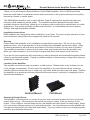
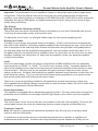
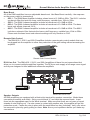
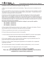
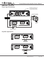
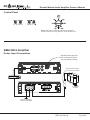
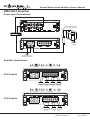
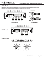
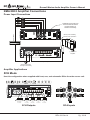
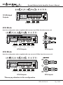
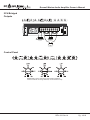
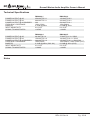
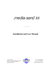
Roswell Marine Audio
Amplifier Owner’s Manual
RMA 600.1 C920-0029
RMA 500.2 C920-0030
RMA 600.4 C920-0031
RMA 800.5 C920-0032
REV. 02-Feb-14
Pg. 1/19
Roswell Marine Audio Amplifier Owner’s Manual
Thank you for purchasing a Roswell Marine Audio (RMA) Amplifier. Since 1998 Roswell has
been the world leader in wakeboard towers and accessories in the marine industry and is quickly
becoming a leader in marine audio.
This RMA Marine Amplifier uses a super-efficient Class D topology that significantly improves
efficiency while enhancing sound quality. The amplifier has been designed using the latest
available electronic technology, allowing you to produce high quality stereo reproduction in mobile
applications. This system provides low harmonic distortion, a considerable amount of reserve
voltage, and high temperature stability.
Installation Instructions
RMA amplifiers are designed for easy installation in your boat. To ensure proper operation of your
new investment, please follow the suggestions listed in this manual.
Warning
Please check the suitability of the installation location before you begin. Do not cut any of the
boat’s structure. Pay close attention to what is behind any bulkheads, panels and carpet. Often
the boat manufacturer will hide wires and cables in the exact location you may wish to install in.
The amplifier is sensitive to electrical and motor noise and interference from the amplifier may
affect your radio reception, try mounting the amp at least three feet away from the receiver.
If you do not have experience with automotive or marine electrical and mechanical systems please
contact a professional installer. Paying a qualified installer is almost always cheaper than paying a
dealership to repair your boat.
Location of the Amplifier
The amplifier must be securely mounted to a solid surface. Please select a dry location such as
in the storage compartment. Do not mount the amplifier to any area that may have excessive
vibration (like the subwoofer box) or under any cup holder drain lines that may leak water. Position
the amplifier in an area that receives sufficient airflow and mount it vertically or completely flat for
optimal heat dissipation.
Vertical Mount
Flat Mount
Supplying Enough Power
Your amplifier converts power, or current, from your boat’s electrical system and turns it into high
power audio energy. If the amp does not get all the power it needs, it will not produce its full
output. If the voltage or current drops too low, the amplifier will drop below it’s rated output. Make
sure your boats charging system is in good working order. Any hi-performance audio amplifier will
increase the demand on your alternator and battery. If you are unsure, have your charging system
tested by a professional technician.
REV. 02-Feb-14
Pg. 2/19
Roswell Marine Audio Amplifier Owner’s Manual
Important: The performance of your amplifier is reliant on using high quality marine grade wiring
components. There are inherent risks when using low-cost wiring materials with a high power
amplifier, most critical of which is overheating. A full RMA Wiring Kit (C920-0003) can be purchased
separately through an RMA dealer, we highly recommend using our wiring kit as it ensures high
quality wiring and fusing.
The Ground
Warning: Read the following carefully
The ground wire should be connected directly to the battery of your boat. Remember, the ground
must carry the same high current as the positive wire.
To reduce the risk of noise, run all signal cables away from any power supplying wires.
Running the Cables
Carefully run your power and ground wires to the battery. 4 AWG is the minimum recommended
wire size for this amplifier. If powering multiple amplifiers from the same power wire, verify the wire
size is adequate for the total amp draw. Roswell recommends using full spec wiring adequate for
the total amp draw from the amplifiers being powered. You must install a main fuse within 12” of
the battery rated for the total amount of amplifiers used. You must also use an in-line fuse for each
amplifier, installing it no further than 18” away from the amplifier (check your particular amplifier
model for fuse rating).
Level
Due to the wide range of head unit output configurations all RMA amplifiers have an adjustable
input sensitivity or “LEVEL” or “GAIN”. The level is not a volume control. It properly matches the
input of the amplifier to the output of the head unit and makes the amplifier more sensitive to input
from the stereo. With the level up, the amplifier will reach maximum output at a lower volume
setting on the deck. At higher level settings the amplifier becomes more sensitive to noise from the
boats electrical system. Try to run the level at the lowest setting possible for your system for the
best sound quality while still achieving full power output.
There is no correct level setting suitable for all applications as head unit preamp outputs vary.
Since speakers have different power requirements to reach the same output, the level is most often
needed to compensate for these differences.
Protection Indicator
This amplifier is equipped with an advanced protection system. If for any reason this unit goes into
protection mode it will flash a solid single red LED light found on the control end of the amplifier.
Control Panel
The control panel can be found under the cover located on the face of the amplifier. To access the
control panel remove the cover by unfastening the two screws using the included Allen key.
Crossover Controls
Note: All frequency markings are intended as guidelines only, the only way to set these dials
exactly is with an oscilloscope.
A crossover is a device that removes unwanted frequencies from a speaker or amplifier and
enhances the desired ones. A tweeter can easily be blown by bass frequencies if they are not
REV. 02-Feb-14
Pg. 3/19
Roswell Marine Audio Amplifier Owner’s Manual
filtered out. A subwoofer will not sound natural if it is playing mid range frequencies. Careful
adjustment is needed to ensure that all speakers are playing the right frequencies and that they are
left with no gaps in the frequency response.
• HPF (High-Pass Filter) - A high-pass filter allows high frequency signals to pass through while
reducing all signals lower than the cutoff frequency setting on its dial.
HPF Frequency Response Curve
Amplitude (dB)
(illustrates crossover set at 90Hz)
60
70
80
90
100
110
120
130
140
150
Frequency (Hz)
•
LPF (Low-Pass Filter) - A low-pass filter allows low frequency signals to pass through while
reducing all signals higher than the cutoff frequency setting on its dial.
LPF Frequency Response Curve
Amplitude (dB)
(illustrates crossover set at 80Hz)
10
•
20
30
40
50
60
70
80
90
100
Frequency (Hz)
Bandpass Filter (BP) - Uses both the high-pass and low-pass filters in order to only play a
selected range of frequencies.
BPF Frequency Response Curve
Amplitude (dB)
(illustrates HPF set at 40Hz & LPF set at 80Hz)
10
20
30
40
50
60
70
80
90
100
Frequency (Hz)
•
•
•
Subsonic - A Subsonic filter allows higher frequency signals to pass through while reducing
all signals lower than the cutoff frequency set on its dial. This allows you to remove unwanted
frequencies in order to protect your equipment. Typically this should be set in the 30Hz range.
Note: As an added benefit to you, all low-pass filters work in conjunction with the high-pass to
function as a bandpass. In low-pass mode your high-pass dial functions as a subsonic filter.
We recommend this be set around 30Hz as anything below this level is wasting battery power
and could cause potential damage to your speaker.
Full - Allows the full range of frequencies to pass through.
Double - This setting applies the crossover settings of channels 3 and 4 to all four channels.
This applies to the 600.4 amplifier only. Typically this setting is used when powering two
identical speakers in bridged mode.
REV. 02-Feb-14
Pg. 4/19
Roswell Marine Audio Amplifier Owner’s Manual
Bass Boost
All of the RMA amplifiers have an adjustable bass boost. Use Bass Boost carefully - the response
on the power output is tremendous!
• 600.1 - The RMA Mono Amplifier includes a bass boost of 0-12dB at 45Hz. The 600.1 includes
a subsonic filter that sets the lower cutoff frequency, variable from 15Hz to 55Hz.
• 500.2 - The RMA 2-channel amplifier includes a bass boost of 0-12dB at 45Hz.
• 600.4 - The RMA 4-channel amplifier includes a bass boost of 0-12dB at 45Hz. The bass
boost only affects channels 3 & 4.
• 800.5 - The RMA 5-channel amplifier includes a bass boost of 0-12dB at 45Hz. The 800.5
includes a subsonic filter that sets the lower cutoff frequency, variable from 15Hz to 55Hz.
Please note the bass boost and subsonic settings will only function on CH5.
Remote Gain Control
• The RMA 600.1, 500.2, and 800.5 Amplifiers include a remote gain control module that can
be plugged into the amplifier to allow easy reduction of the gain setting without accessing the
amplifier.
Remote Gain Control Module
RCA cable
RCA Line Out - The RMA 600.1, 500.2, and 500.4 amplifiers all have line out connections that
allow you to connect multiple amplifiers together. The RCA pre-outs supply a full range mono signal
as they are designed to feed additional subwoofer amplifiers.
Optional full range line out
Speaker Outputs
connection
to additional
All RMA amplifiers are equipped with a block style terminal for
speaker
connection. Make these
amplifiers in the system
connections carefully and neatly. Strip your wire back ⅝” and twist the exposed leads. Insert
them into the appropriate spot on the block terminal. Make sure that there are no loose or frayed
strands of wire sticking out. If a wire comes in contact with another wire, the amplifier will go into
protection mode. Fasten the wire in place with the small Allen hex key (included). Verify your wires
are secured in place by gently pulling on them. Note: Know your impedance before you make any
connections.
REV. 02-Feb-14
Pg. 5/19
Roswell Marine Audio Amplifier Owner’s Manual
Installation Instructions (Reference Diagrams on Page 7 to 11)
1. Disconnect the negative cable from the boat battery. Tape up the end so it is isolated from the
battery.
2. Run a red 4 AWG wire from the battery to the amplifier. Plan this part of the installation carefully.
This cable will carry a very high current (or battery switch common post). If it should short to any
metal and is not properly fused it could catch fire.
3. Connect an in-line fuse holder to the power cable no further than 12” away from the positive
battery terminal. If one amplifier is being used, refer to the table below for recommended fuse
rating. If two or more amplifiers are being used, verify the fuse and wire are capable of handling the
total current load of all amplifiers connected. To protect each amplifier, use an in-line fuse holder or
fused distribution block within 18” of the amplifiers, again referring to the table below. Do not install
the fuse(s) until the end of the installation.
Please refer to the following recommended fuse ratings for your specific amplifier:
• 600.1 Amplifier - 50 Amp Fuse
• 500.2 Amplifier - 40 Amp Fuse
• 600.4 Amplifier - 50 Amp Fuse
• 800.5 Amplifier - 80 Amp Fuse
4. Run the black 4 AWG ground wire directly to the negative (-12V) pole on the battery. This wire
should handle the load in the previous step and be as short as possible.
5. Wire your speakers and route wires to your amp mounting location.
6. Connect the power and the ground wires to the amplifier.
7. Connect the blue remote wire from the head unit to the “REMOTE” connection of the amplifier.
** Only after this step should you install the fuse at the battery**
8. Turn on the amplifier to verify it is wired correctly and does not go into protection mode. The
power LED should turn solid green after a few seconds.
9. Once you verify you have a steady green light please turn the amplifier off to complete the
remaining connections.
10. Connect the speaker wires to the amplifier, making sure the polarity (+ and -) are correct.
11. Connect the RCAs to the appropriate inputs on the amplifier.
You must now set the controls on the amplifier.
This is the most important part of an amplifiers installation and should be
completed by a trained audio professional.
REV. 02-Feb-14
Pg. 6/19
Roswell Marine Audio Amplifier Owner’s Manual
RMA 600.1 Amplifier
Power Input Connections
Supplied remote gain can
be connected to reduce
the gain setting remotely
RCA cable
50 amp fuse at battery
for wire short protection
+
12V
Ba
-
tter
y
(-) Ground to
amplifier
+12V wire (4 AWG)
Ground connection
directly to the battery
Amplifier Applications
Subwoofer
2–8 ohms
Subwoofer
4–8 ohms
Subwoofer
4–8 ohms
REV. 02-Feb-14
Pg. 7/19
Roswell Marine Audio Amplifier Owner’s Manual
Control Panel
Please note: These controls are approximate guidelines
and have natural occurring variances, use as reference only.
RMA 500.2 Amplifier
Power Input Connections
Supplied remote gain can
be connected to reduce
the gain setting remotely
RCA cable
40 amp fuse at battery
for wire short protection
+
12V
Ba
-
tter
y
(-) Ground to
amplifier
+12V wire (4 AWG)
Ground connection
directly to the battery
REV. 02-Feb-14
Pg. 8/19
Roswell Marine Audio Amplifier Owner’s Manual
Amplifier Applications
2CH Outputs
CH 2
2–8 ohms
CH 1
2–8 ohms
Bridged Mono
Output
Subwoofer
4–8 ohms
Control Panel
Please note: These controls are approximate guidelines
and have natural occurring variances, use as reference only.
REV. 02-Feb-14
Pg. 9/19
Roswell Marine Audio Amplifier Owner’s Manual
RMA 600.4 Amplifier
Power Input Connections
RCA cables
50 amp fuse at battery
for wire short protection
+
12V
Ba
-
tter
y
(-) Ground to
amplifier
+12V wire (4 AWG)
Ground connection
directly to the battery
Amplifier Applications
4CH Outputs
CH 4
2–8 ohms
CH 3
2–8 ohms
CH 2
2–8 ohms
CH 1
2–8 ohms
3CH Outputs
Subwoofer
4–8 ohms
CH 2
2–8 ohms
CH 1
2–8 ohms
REV. 02-Feb-14
Pg. 10/19
Roswell Marine Audio Amplifier Owner’s Manual
2CH Mode
Note: When the ‘double’ setting is selected this configuration ensures that all speakers are tuned
the same when powering two or four identical speakers from this amplifier.
CH 4
2–8 ohms
CH 3
2–8 ohms
CH 2
2–8 ohms
CH 1
2–8 ohms
4CH Outputs
RCA Inputs
2CH Outputs
Subwoofer
4–8 ohms
Subwoofer
4–8 ohms
Control Panel
Please note: These controls are approximate guidelines
and have natural occurring variances, use as reference only.
REV. 02-Feb-14
Pg. 11/19
Roswell Marine Audio Amplifier Owner’s Manual
RMA 800.5 Amplifier Connections
Power Input Connections
Supplied remote gain can
be connected to reduce
the gain setting of
channel 5 remotely
RCA cables
80 amp fuse at battery
for wire short protection
+
12V
-
Ba
tter
y
(-) Ground to
amplifier
+12V wire (4 AWG)
Ground connection
directly to the battery
Amplifier Applications
5CH Mode
Use this configuration when supplied with front, rear, and subwoofer RCAs from the source unit.
Subwoofer
2–8 ohms
CH 4
2–8 ohms
CH 3
2–8 ohms
5CH Outputs
CH 2
2–8 ohms
CH 1
2–8 ohms
RCA Inputs
REV. 02-Feb-14
Pg. 12/19
Roswell Marine Audio Amplifier Owner’s Manual
3CH Bridged
Outputs
Subwoofer
2–8 ohms
CH 3/4
4–8 ohms
CH 1/2
4–8 ohms
4CH Mode
Use this configuration when supplied with front and rear RCAs from the source unit.
Subwoofer
2–8 ohms
CH 4
2–8 ohms
CH 3
2–8 ohms
CH 2
2–8 ohms
CH 1
2–8 ohms
4CH Outputs
RCA Inputs
2CH Mode
Use this configuration when supplied with only one set of RCAs from the source unit.
Subwoofer
2–8 ohms
*CH 3
2–8 ohms
*CH 4
2–8 ohms
CH 2
2–8 ohms
CH 1
2–8 ohms
2CH Outputs
RCA Inputs
*Please pay attention to this configuration
REV. 02-Feb-14
Pg. 13/19
Roswell Marine Audio Amplifier Owner’s Manual
2CH Bridged
Outputs
Subwoofer
2–8 ohms
RIGHT
4–8 ohms
LEFT
4–8 ohms
Control Panel
Please note: These controls are approximate guidelines
and have natural occurring variances, use as reference only.
REV. 02-Feb-14
Pg. 14/19
Roswell Marine Audio Amplifier Owner’s Manual
Technical Specifications
POWER OUTPUT @ 4Ω
POWER OUTPUT @ 2Ω
POWER OUTPUT @ 4Ω BRIDGED
FREQUENCY RESPONSE
BASS EQ
INPUT SENSITIVITY
SIGNAL TO NOISE RATIO
RMA 600.1
350 WATTS X 1
600 WATTS X 1
N/A
10Hz-150Hz
0-12dB @ 45Hz
0.2~5.0V
>107dB
RMA 500.2
150 WATTS X 2
250 WATTS X 2
500 WATTS X 1
10Hz-50kHz
0-12dB @ 45Hz
0.2~5.0V
>104dB
POWER OUTPUT @ 4Ω
POWER OUTPUT @ 2Ω
POWER OUTPUT @ 4Ω BRIDGED
FREQUENCY RESPONSE
BASS EQ
INPUT SENSITIVITY
SIGNAL TO NOISE RATIO
RMA 600.4
90 WATTS X 4
150 WATTS X 4
300 WATTS X 2
10Hz-50kHz
0-12dB @ 45Hz (CH3 & 4)
0.2~5.0V
>104dB
RMA 800.5
75 WATTS X 4 + 250W
100 WATTS X 4 + 375W
150 WATTS X 2 + 250/375W
10Hz-50kHz / 10Hz-150Hz (CH5)
0-12dB @ 45Hz (CH5)
0.2~5.0V
>104dB
Notes
REV. 02-Feb-14
Pg. 15/19
Roswell Marine Audio Amplifier Owner’s Manual
Notes
REV. 02-Feb-14
Pg. 16/19
Roswell Marine Audio Amplifier Owner’s Manual
Notes
REV. 02-Feb-14
Pg. 17/19
Roswell Marine Audio Amplifier Owner’s Manual
CAUTION!
RMA 600.1, 500.2, 600.4 & 800.5 Amplifiers
AMPLIFIER MAY BECOME VERY HOT DURING NORMAL OPERATION
Your new Roswell Marine Audio amplifier possesses exceptional efficiency and thermal
management. However, it is possible that, if mounted in a confined space and/or high
temperature environment, it may become extremely hot during periods of extended use.
Special attention must be given during the installation process to optimize cooling efficiency. An
unobstructed airflow around the amplifier’s heat sink is required to enable proper cooling.
For optimal performance Roswell recommends mounting the amplifier as follows:
Vertical Mount
Flat Mount
Mounting the amplifier in a position that does not enable proper cooling will affect the
performance of the unit and is strongly discouraged.
IN ADDITION TO PROPER MOUNTING, ENSURE THAT NO ITEMS ARE
IN DIRECT CONTACT WITH AMPLIFIER
Life vests, wet suits, towels, coolers, and other like items must be kept away from amplifier.
Roswell Wake-Air is not liable for damage resulting from improper mounting and/or negligent
use of this product.
Warning! Continuous exposure to sound pressure levels over 100dB may cause permanent hearing
loss. High power autosound system may product sound pressure levels well over 130dB, use
common sense and practice safe sound!
REV. 02-Feb-14
Pg. 18/19
Roswell Marine Audio Amplifier Owner’s Manual
ROSWELL MARINE AUDIO WARRANTY AND SERVICE GUIDELINES
Roswell Wake Air warrants all new RMA Series amplifiers against defects in material and
workmanship for a period of ONE (1) YEAR from the original date of purchase. This warranty is
not transferable and applies only to the original retail purchaser from an authorized Roswell Marine
Audio retailer. Upon inspection by Roswell Wake Air, should service be necessary under this
warranty for any reason due to manufacturer defects, Roswell Wake Air will, at our own discretion,
repair or replace the defective product with new or similar conditioned product at no charge.
THIS WARRANTY DOES NOT COVER INSTALLATION OR DAMAGE RESULTING
FROM ACCIDENT, MISUSE, ABUSE, IMPROPER WIRING, OPERATION OUTSIDE OF
THE MANUFACTURERS RECOMMENDATIONS OR SPECIFICATIONS, OR AGAINST
INSTRUCTIONS IN OWNERS MANUAL. IN ADDITION, ANY PRODUCT THAT HAS BEEN
OPENED, TAMPERED WITH OR MODIFIED, OR IF ANY SERIAL NUMBERS HAVE BEEN
REMOVED, WILL NOT BE COVERED BY ANY PART OF THE MANUFACTURES WARRANTY.
All warranty claims must first be made in direct contact with Roswell Wake Air’s warranty
department. When first contact is made the warranty representative will issue an RA # to open
a claim. All warranty returns should be sent to Roswell Wake Air freight prepaid and must
be accompanied by proof of purchase (a copy of original sales receipt). Direct returns from
consumers or non-authorized retailers will be refused unless specifically authorized by Roswell
Wake Air with a valid return authorization number (RA#).
All warranty returns should be packed in the original packaging and must be accompanied by a
copy of the original sales receipt. Product damage during shipping will not be covered under this
warranty. The customer or retailer may choose to have this damage repaired at the normal “Out of
Warranty” repair cost.
In no event will Roswell Wake Air be liable for incidental, consequential, or other damages resulting
from the use of this product. This includes but is not limited to, damage of hearing, property of
person, damage based upon inconvenience or on loss of use of the product, and to the extent
permitted by law, damages for personal injury.
This warranty applies to products being sold and used in the United States of America and Canada.
In all other countries please contact your authorized Roswell Wake Air representative.
For warranty and non-warranty repairs, please contact Roswell Wake Air:
Phone: 1.855.962.WAKE (9253)
Email: [email protected]
REV. 02-Feb-14
Pg. 19/19