1
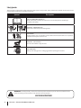
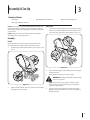
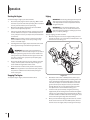
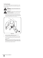
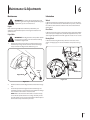
Safe Operation Practices • Set-Up • Operation • Maintenance • Service • Troubleshooting • Warranty Operator’s Manual Lawn Edger — 550 Series WARNING READ AND FOLLOW ALL SAFETY RULES AND INSTRUCTIONS IN THIS MANUAL BEFORE ATTEMPTING TO OPERATE THIS MACHINE. FAILURE TO COMPLY WITH THESE INSTRUCTIONS MAY RESULT IN PERSONAL INJURY. MTD LLC, P.O. BOX 361131 CLEVELAND, OHIO 44136-0019 Printed In USA Form No. 769-04243 (May 1, 2012) 1 To The Owner Thank You Thank you for purchasing an MTD Lawn Edger. It was carefully engineered to provide excellent performance when properly operated and maintained. If applicable, the power testing information used to establish the power rating of the engine equipped on this machine can be found at www.opei.org or the engine manufacturer’s web site. Please read this entire manual prior to operating the equipment. It instructs you how to safely and easily set up, operate and maintain your machine. Please be sure that you, and any other persons who will operate the machine, carefully follow the recommended safety practices at all times. Failure to do so could result in personal injury or property damage. If you have any problems or questions concerning the machine, phone your local authorized MTD service dealer or contact us directly. MTD’s Customer Support telephone numbers, website address and mailing address can be found on this page. We want to ensure your complete satisfaction at all times. All information in this manual is relative to the most recent product information available at the time of printing. Review this manual frequently to familiarize yourself with the machine, its features and operation. Please be aware that this Operator’s Manual may cover a range of product specifications for various models. Characteristics and features discussed and/or illustrated in this manual may not be applicable to all models. We reserve the right to change product specifications, designs and equipment without notice and without incurring obligation. Throughout this manual, all references to right and left side of the machine are observed from the operating position The engine manufacturer is responsible for all engine-related issues with regards to performance, power-rating, specifications, warranty and service. Please refer to the engine manufacturer’s Owner’s/Operator’s Manual, packed separately with your machine, for more information. Table of Contents Safe Operation Practices......................................... 3 Assembly & Set-Up................................................... 6 Features & Controls.................................................. 8 Operation.................................................................. 9 Maintenance & Adjustment..................................12 Service......................................................................14 Troubleshooting......................................................15 Record Product Information Model Number Before setting up and operating your new equipment, please locate the model plate on the equipment and record the information in the provided area to the right. You can locate the model plate by standing at the operator’s position and looking down at the rear of the machine. This information will be necessary, should you seek technical support via our web site, Customer Support Department, or with a local authorized service dealer. Serial Number Customer Support Please do NOT return the machine to the retailer or dealer without first contacting the Customer Support Department. If you have difficulty assembling this product or have any questions regarding the controls, operation, or maintenance of this machine, you can seek help from the experts. Choose from the options below: ◊ Visit us on the web at www.mtdproducts..com See How-to Maintenance and Parts Installation Videos at www.mtdparts.com/KnowledgeCenter 2 ◊ Call a Customer Support Representative at 1300 951 594 ◊ Write to MTD Products Australia Pty Ltd. • P.O. Box 376 • Dandenong. Vic. • 3175 2 Important Safe Operation Practices WARNING! This symbol points out important safety instructions which, if not followed, could endanger the personal safety and/or property of yourself and others. Read and follow all instructions in this manual before attempting to operate this machine. Failure to comply with these instructions may result in personal injury. When you see this symbol. HEED ITS WARNING! CALIFORNIA PROPOSITION 65 WARNING! Engine Exhaust, some of its constituents, and certain vehicle components contain or emit chemicals known to State of California to cause cancer and birth defects or other reproductive harm. DANGER! This machine was built to be operated according to the safe operation practices in this manual. As with any type of power equipment, carelessness or error on the part of the operator can result in serious injury. This machine is capable of amputating fingers, hands, toes and feet and throwing objects. Failure to observe the following safety instructions could result in serious injury or death. Training Preparation 1. Read this operator’s manual carefully in its entirety before attempting to assemble this machine. Read, understand, and follow all instructions on the machine and in the manual(s) before operation. Keep this manual in a safe place for future and regular reference and for ordering replacement parts. 1. Thoroughly inspect the area where the equipment is to be used. Remove all stones, sticks, wire, bones, toys and other foreign objects which could be tripped over or picked up and thrown by the blade. Thrown objects can cause serious personal injury. 2. 2. Be completely familiar with the controls and the proper use of this machine before operating it. 3. This machine is a precision piece of power equipment, not a plaything. Therefore, exercise extreme caution at all times. Your machine has been designed to perform one job: to edge lawn. Do not use it for any other purpose. Always wear safety glasses or safety goggles during operation and while performing an adjustment or repair to protect your eyes. Thrown objects which ricochet can cause serious injury to the eyes. 3. Wear sturdy, rough-soled work shoes and close-fitting slacks and shirts. Shirts and pants that cover the arms and legs and steel-toed shoes are recommended. Never operate this machine in bare feet, sandals, slippery or light weight (e.g. canvas) shoes. 4. Never attempt to make any adjustments while the engine is running, except where specifically recommended in the operator’s manual. 4. 5. 6. Never allow children under 14 years of age to operate this machine. Children 14 and over should read and understand the instructions and safe operation practices in this manual and on the machine and be trained and supervised by an adult. Only responsible individuals who are familiar with these rules of safe operation should be allowed to use this machine. To help avoid blade contact or a thrown object injury, stay in operator zone behind handles and keep children, bystanders, helpers and pets at least 75 feet from lawn edger while it is in operation. Stop machine if anyone enters area. Safe Handling Of Gasoline: To avoid personal injury or property damage use extreme care in handling gasoline. Gasoline is extremely flammable and the vapors are explosive. Serious personal injury can occur when gasoline is spilled on yourself or your clothes which can ignite. Wash your skin and change clothes immediately. a. Use only an approved gasoline container. 3 b. c. d. Never fill containers inside a vehicle or on a truck or trailer bed with a plastic liner. Always place containers on the ground away from your vehicle before filling. Remove gas-powered equipment from the truck or trailer and refuel it on the ground. If this is not possible, then refuel such equipment on a trailer with a portable container, rather than from a gasoline dispenser nozzle. Keep the nozzle in contact with the rim of the fuel tank or container opening at all times until fueling is complete. Do not use a nozzle lock-open device. Muffler and engine become hot and can cause a burn. Do not touch. 8. Never operate this machine without good visibility or light. Always be sure of your footing and keep a firm hold on the handles. Walk, never run. 9. Do not operate this machine if it has been dropped or damaged. Return machine to your nearest authorized servicing dealer for examination and repair. 10. Do not operate this machine with a damaged or excessively worn cutting blade. 11. Never attempt to clear material from the blade guard while the engine is running. Shut the engine off, disconnect the spark plug wire and ground against the engine to prevent unintended starting. e. Extinguish all cigarettes, cigars, pipes and other sources of ignition. f. Never fuel machine indoors because flammable vapors will accumulate in the area. 12. Do not overload machine capacity by attempting to edge at too fast of a rate. g. Never remove gas cap or add fuel while engine is hot or running. Allow engine to cool at least two minutes before refueling. 13. h. Never over fill fuel tank. Fill tank to no more than ½ inch below bottom of filler neck to provide for fuel expansion. 14. Do not operate machine in rain or wet soil conditions. Stay alert for uneven sidewalks, terrain etc. Always push slowly over rough surfaces. Do not use this machine on gravel surfaces. 15. Always operate machine from behind the handles and position yourself where the direct line of sight to cutting blade is blocked by guards. i. Replace gasoline cap and tighten securely. j. If gasoline is spilled, wipe it off the engine and equipment. Move machine to another area. Wait 5 minutes before starting engine. 16. Always stop engine when edging or trimming is delayed or when transporting machine from one location to another. k. Never store the machine or fuel container near an open flame, spark or pilot light as on a water heater, space heater, furnace, clothes dryer or other gas appliances. 17. Never leave a running machine unattended. Stop the engine, disconnect spark plug wire and ground against the engine to prevent unintended starting. l. To reduce fire hazard, keep lawn edger free of grass, leaves, or other debris build-up. Clean up oil or fuel spillage and remove any fuel soaked debris. m. Allow a lawn edger to cool at least five (5) minutes before storing.. Operation 4 7. 1. Do not put hands or feet near rotating parts. Contact with the rotating blade can amputate hands and feet. 2. The blade control handle is a safety device. Never bypass its operation. Doing so, makes the machine unsafe and may cause personal injury. 3. Never operate without blade guard, debris shield and blade control handle in place and working. 4. Never operate with damaged safety devices. Failure to do so, can result in personal injury. 5. Never run an engine indoors or in a poorly ventilated area. Engine exhaust contains carbon monoxide, an odorless and deadly gas. 6. Do not operate machine while under the influence of alcohol or drugs. Section 2 — Important Safe Operation Practices 18. Only use parts and accessories made for this machine by the manufacturer. Failure to do so, can result in personal injury. 19. If situations occur which are not covered in this manual, use care and good judgment. Contact Customer Support for assistance or the name of your nearest service dealer. Children Tragic accidents can occur if the operator is not alert to the presence of children. Children are often attracted to power equipment such as lawn edgers. They do not understand the dangers. Never assume that children will remain where you last saw them. 1. Keep children out of the edging area and under watchful care of a responsible adult other than the operator. 2. Be alert and turn lawn edger off if a child enters the area. 3. Before and while moving backwards, look behind and down for small children. 4. Use extreme care when approaching blind corners, doorways, shrubs, trees, or other objects that may obscure your vision of a child who may run into the lawn edger. 5. Keep children away from hot or running engines. They can suffer burns from a hot muffler. 6. Never allow children under 14 years of age to operate this machine. Children 14 and over should read and understand the instructions and safe operation practices in this manual and on the machine and be trained and supervised by an adult. Maintenance and Storage 1. Never run an engine indoors or in a poorly ventilated area. Engine exhaust contains carbon monoxide, an odorless and deadly gas. 2. Before cleaning, repairing, or inspecting, make certain the blade and all moving parts have stopped. Disconnect the spark plug wire and ground against the engine to prevent unintended starting. 3. Check the blade and engine mounting bolts at frequent intervals for proper tightness. Also, visually inspect blade for damage (e.g., bent, cracked, worn) Replace blade with the original equipment manufacture’s (O.E.M.) blade only, listed in this manual. “Use of parts which do not meet the original equipment specifications may lead to improper performance and compromise safety!” 4. Lawn edger blades are sharp and can cut. Wrap the blade or wear gloves, and use extra caution when servicing them. 5. Keep all nuts, bolts, and screws tight to be sure the equipment is in safe working condition. 6. Never tamper with safety devices. Check their proper operation regularly. 7. After striking a foreign object, stop the engine, disconnect the spark plug wire and ground against the engine. Thoroughly inspect the lawn edger for any damage. Repair the damage before starting and operating the lawn edger. 8. Never attempt to make a wheel adjustment while the engine is running. 9. Many components on your new edger can wear with continued use. For safety protection, frequently check all edger components and replace immediately with original equipment manufacturer’s (O.E.M.) parts only, listed in this manual. “Use of parts which do not meet the original equipment specifications may lead to improper performance and compromise safety!” 10. Do not change the engine governor setting or overspeed the engine. The governor controls the maximum safe operating speed of the engine. 11. Maintain or replace safety and instruction labels, as necessary. 13. According to the Consumer Products Safety Commission (CPSC) and the U.S. Environmental Protection Agency (EPA), this product has an Average Useful Life of seven (7) years, or 70 hours of operation. At the end of the Average Useful Life have the machine inspected annually by an authorized service dealer to ensure that all mechanical and safety systems are working properly and not worn excessively. Failure to do so can result in accidents, injuries or death. Spark Arrestor WARNING! This machine is equipped with an internal combustion engine and should not be used on or near any unimproved forest-covered, brushcovered or grass-covered land unless the engine’s exhaust system is equipped with a spark arrestor meeting applicable local or state laws (if any). If a spark arrestor is used, it should be maintained in effective working order by the operator. In the State of California the above is required by law (Section 4442 of the California Public Resources Code). Other states may have similar laws. Federal laws apply on federal lands. A spark arrestor for the muffler is available through your nearest engine authorized service dealer or contact the service department, P.O. Box 361131 Cleveland, Ohio 44136-0019. 12. Observe proper disposal laws and regulations for used gas, oil, etc.. Improper disposal of fluids and materials can harm the environment. Section 2 — Important Safe Operation Practices 5 Safety Symbols This page depicts and describes safety symbols that may appear on this product. Read, understand, and follow all instructions on the machine before attempting to assemble and operate. Symbol Description READ THE OPERATOR’S MANUAL(S) Read, understand, and follow all instructions in the manual(s) before attempting to assemble and operate WARNING— ROTATING BLADES Keep hands and feet away from rotating blade. BYSTANDERS Keep bystanders, pets, and children at least 75 feet from the machine while it is in operation. Stop machine if anyone enters the area. WARNING— HOT SURFACES Do not touch muffler or adjacent areas. EYE PROTECTION Always wear safety glasses or safety goggles when operating this machine. WARNING! Your Responsibility—Restrict the use of this power machine to persons who read, understand and follow the warnings and instructions in this manual and on the machine. SAVE THESE INSTRUCTIONS! 6 Section 2 — Important Safe Operation Practices 3 Assembly & Set-Up Contents of Carton • One Edger • • One Engine Operator’s Manual One Edger Operator’s Manual NOTE: This machine is shipped WITHOUT GASOLINE or OIL. After setting up the edger, service the engine with gasoline and oil as instructed in the separate Engine Operator’s Manual packed with your machine. • One 18 oz. Bottle Engine Oil Starter Rope 1. NOTE: Reference to the right or left hand side of the edger is observed from the operating position. Locate the rope guide found on the right side of the upper handle. Loosen, but do NOT remove, the wing knob which secures the rope guide to the upper handle. See Fig. 3–2. Assembly 2 Handle Remove and discard any packaging cardboard that may be present between the upper handle and the lower handle. 1. Pivot the upper handle upward until it snaps into place. See Fig. 3–1. 3 1 1 4 Figure 3-2 2. Stand behind the edger and hold the blade control against the upper handle. 3. Gently pull the starter rope out of the engine. WARNING! The edger blade WILL rotate when the starter rope is pulled. 2 NOTE: The starter rope will not pull out of the engine unless the blade control (refer to Fig. 3–2) is depressed against the upper handle. Figure 3-1 2. Tighten the hand knobs, which are located on both the left and right sides of the handle. 4. Slip the starter rope through the top of the rope guide. Retighten the wing knob which secures the rope guide to the upper handle. 7 Adjustments Bevel Adjustment The angle of the edger blade can be adjusted by placing the bevel adjustment in one of three positions for edging. See Fig. 3–3. Figure 3-3 Set-Up Gas & Oil Fill-Up Service the engine with gas and oil as instructed in the Engine Operator’s Manual package separately with your edger. Read instructions carefully. WARNING! Use extreme caution when handling gasoline. Gasoline is extremely flammable and the vapors are explosive. Never fuel the machine indoors or while the engine is hot or running. Extinguish cigarettes, cigars, pipes and other sources of ignition. 8 Section 2— Assembly & Set-Up 4 Controls and Features Blade Control Blade Depth Control Lever Starter Rope/ Recoils Starter Primer Bevel Adjustment Lever Curb Height Adjustment Lever Figure 4-1 Edger controls and features are described below and illustrated Blade Control in Fig. 4-1. Located on the upper handle, the blade control must be WARNING! Be familiar with all the controls and depressed against the upper handle in order to operate the their proper operation, and know how to stop the edger. Releasing the blade control stops the engine and the machine and disengage it quickly. edger blade. NOTE: For detailed information on all engine controls, refer to Blade Depth Control Lever the separate Engine Operator’s Manual. The blade depth control lever is located on the right side of Starter Rope / Recoil Starter the upper handle. It is used to control the depth of the cut. The further forward the blade depth control lever is moved, the The starter rope/recoil starter is used to start the engine. deeper into the soil the edger blade will cut. Primer The primer is used to pump gas into the carburetor and aid in starting the engine. Use it to start a cold engine, but do not use it to restart a warm engine after a short shutdown. Curb Height Adjustment Lever Bevel Adjustment Lever The bevel adjustment lever is located on the front, left portion of the edger, behind the edger blade. It is used to vary the angle of the edger blade between one of three positions for edging, trenching or beveled edging. The curb height adjustment lever is found on the rear portion of the edger. When placed in an applicable notch, it aids in stabilizing the edger while edging grass along a curb. 9 5 Operation Starting the Engine Edging To start the edger’s engine, proceed as follows: 1. Attach the spark plug wire to the spark plug. Make certain the metal cap on the end of the spark plug wire is fastened securely over the metal tip on the spark plug. 2. Move the blade depth control lever back to the START position in the adjacent (top) notch. 3. Depress the primer bulb three times, pausing two to three seconds between each push. In cold weather (below 50°F /19°C), it may be necessary to depress the primer bulb four or five times. WARNING! The rotating cutting blade may throw objects and cause personal injury. Keep the area clear of bystanders and do not operate it without the guards in place. WARNING! Do not lower the blade if it is over concrete, asphalt, rocks or the like. The blade can strike the supporting surface, resulting in personal injury or property damage. To begin edging, proceed as follows: 1. NOTE: Using the primer to restart a warm engine after a short shutdown is usually not necessary. Doing so may result in a flooded engine. 4. Move the edger to an area to be edged, making sure that the left rear wheel is on a hard surface and the blade is over the area to be cut. See Fig. 5–1. Standing behind the edger, depress the blade control and hold it against the upper handle with your left hand. WARNING! This blade control mechanism is a safety device. Never attempt to bypass its operation. 5. With your right hand, grasp the recoil starter handle and slowly pull the rope outward until the engine reaches the start of its compression cycle (the rope will pull slightly harder at this point). 6. After slowly allowing the rope to recoil, pull the rope with a rapid, continuous, full arm stroke. Keep a firm grip on starter handle throughout the entire stroke. 7. Allow the starter handle to slowly return to the eyebolt. NOTE: If the engine fails to start after three pulls, depress the primer an additional two times before pulling the starter rope again. Stopping The Engine To stop the edger’s engine, release the blade control. 10 Figure 5-1 2. With blade control lever in START position, make a pass along the area to be edged before proceeding to the next notch. The further forward the blade depth control lever is moved, the deeper or lower the blade will cut into the ground. Several passes may be necessary to obtain the desired depth of cut. Do not lower the blade more than one depth notch at a time without making a pass. 3. For best results, proceed slowly along the path being edged. Slowly move the edger back and forth through the cutting area, again making sure to keep the left rear wheel on the hard surface and the blade in the cutting path, close to but not touching the edge of the hard surface. 4. Once you have finished edging the selected area, raise the blade control lever back into the START position, move to the next area to be edged, and proceed again from step 1. Edging Along a Curb Beveling The right, rear wheel of the edger can be lowered into one of five positions to ease the task of edging along a curb. To adjust the height of curb wheel, proceed as follows: In order to achieve a bevelled edge, set the bevel adjustment lever (refer to the Assembly & Set-Up Section) in the first (left hand) or third (right hand) notch to place the edger blade in position for beveling. See Fig. 5–3. 1. Lower the right, rear wheel by moving the curb height adjustment lever slightly to the left. See Fig. 5–2. Curb Height Adjustment Lever 1 3 2 Right-Hand Position Left-Hand Position Figure 5-3 Figure 5-2 2. Pivot the right, rear wheel into an applicable position in relation to the height of the curb to be edged along. See Fig. 5–2 3. Release the curb height adjustment lever to lock the wheel in position. See Fig. 5–2. Section 5 — Operation 11 Trenching (If equipped) You can utilize the edger’s optional trenching feature in order to create a wider cutting path for such things as laying wire for landscape lighting. WARNING! Disconnect the spark plug wire and ground against the engine before performing the following steps. WARNING! The edger blade is sharp. Wear leather work gloves to protect your hands when working around the edger blade. 1. Use two wrenches (one wrench to prevent the hex bolt head from spinning and the other to unthread the flange nut) to remove the flange nut that secures the edger blade, leaving the edger blade in place. See Fig. 5–4. Figure 5-4 2. Install the additional edger blade supplied with your machine and the flat washer. See Fig. 5–4. 3. Secure with the flange nut removed earlier. Use a torque wrench to tighten the flange nut to between 37 foot-lbs. and 50 foot-lbs. NOTE: Make certain that the drive belt is seated correctly on the blade spindle and that it is riding smoothly on the spindle sheaves and is not pinched between them. Repeat the first three steps if belt is pinched. 12 Section 5— Operation 6 Maintenance & Adjustments Maintenance Lubrication WARNING! Disconnect the spark plug wire and ground it against the engine before performing any adjustment, repairs or maintenance. Engine Refer to the Engine Operator’s Manual packed with your edger for a detailed description of all engine-related service specifications. Edger Blade WARNING! The edger blade is sharp. Wear leather work gloves to protect your hands when working around the edger blade. 1. Use two wrenches (one wrench to prevent the hex bolt head from spinning and the other to remove the flange nut) to remove the edger blade. Refer to Fig. 6–1. Wheels Lubricate the wheels and bearings at least once a season with a light oil. Also if the wheels are removed for any reason, lubricate the surface of the axle bolt and the inner surface of the wheel with light oil. Pivot Points Lubricate the pivot points on the blade control bail, blade depth control lever, and if applicable, the blade adjustment lever, and curb height adjustment lever with light oil at least once a season. Bearing Block Lubricate the bearing block every 25 hours or at least once a season. Simply apply oil at each end of the cover plate. See Fig. 6–2. Flange Nut Lubricate Edger Blade Figure 6-2 Figure 6-1 2. Remove and discard the edger blade but retain the flange nut. 3. Install the replacement edger blade and the flange nut removed earlier. Use a torque wrench to tighten the flange nut to between 37 foot-lbs. and 50 foot-lbs. NOTE: Make certain that the drive belt is seated correctly on the blade spindle and that it is riding smoothly on the spindle sheaves and is not pinched between them. Repeat the first three steps if the belt is pinched. 13 7 Service Belt Replacement 3. Drive Belt NOTE: To aid in reassembly, note the orientation of the drive belt on the two idler pulleys and the engine flywheel pulley prior to performing the following steps. See Fig. 7-1. Remove the spindle sheaves belt guard by removing the two self-tapping screws which secure it to the blade plate assembly. See Fig. 7-2. Belt Guard Flange Luck Nut Engine Flywheel Pulley Engine Flywheel Pulley Figure 7-2 4. Carefully remove the belt from off of the pulleys, again making sure to note the orientation of the belt. Discard the belt. See Fig. 7-2. 5. Working from the front of the edger, place the belt onto the spindle sheaves, route it back onto the two idler pulleys, and then place it onto the engine flywheel pulley. Figure 7-1 The edger drive belt is subject to wear and should be replaced if any signs of cracking, shredding or rotting are present. To replace the belt, proceed as follows: 1. Working in front of the edger, loosen the flange lock nut on top of the frame, allowing the idler pulley assembly to pivot slightly out from the frame. See Fig. 7-1. 2. With your other hand, carefully reach under the rear of the edger and remove the belt from around the engine flywheel pulley. See Fig. 7-1. NOTE: Make certain that the “V” side of the belt is seated into the top pulley and the flat side of the belt is seated into the bottom pulley. See Fig. 7-2. 6. Reinstall the spindle sheaves belt guard with the self tapping screws removed earlier. 7. Make certain that the drive belt is on the engine flywheel pulley and idler pulleys, and retighten the flange lock nut on the top of the frame. NOTE: Make certain that the drive belt is seated correctly and that it is riding smoothly on the spindle sheaves and is not pinched between them. Repeat the first three steps if the belt is pinched. WARNING! Never operate the edger without the spindle sheaves belt guard in place. 14 Off-Season Storage Observe the following when preparing the edger for long-term storage: 1. Clean and lubricate the edger thoroughly as instructed on the previous page. 2. Refer to the Engine Operator’s Manual packed separately with the edger for engine manufacturers’ storage instructions. 3. Coat the edger blade with chassis grease to prevent rusting and corrosion. 4. Store the edger in a dry, clean area. Do not store next to any corrosive materials, such as lawn fertilizer. 5. Coat the edger, especially any springs and bearings with a light oil or silicone spray. NOTE: When storing any type of power equipment in a poorly ventilated area or metal storage shed, care should be taken to rustproof the equipment. Section 7 — Service 15 8 Troubleshooting Problem Engine fails to start Remedy 1. Dirty air cleaner. 1. Refer to the Engine Operator’s Manual 2. Engine needs to be primed. 2. Push primer bulb two or three times. 3. Fuel tank empty. 3. Fill tank with clean, fresh gasoline. 4. Stale fuel in gasoline tank. 4. Drain gasoline and refill tank with clean, fresh gasoline. 5. Spark plug wire disconnected. 5. Connect the spark plug wire to the spark plug. 6. Spark plug fouled. 6. Clean, adjust gap or replace spark plug. 7. Engine flooded. 7. Refer to the Engine Operator’s Manual. 1. Spark plug wire loose. 1. Connect and tighten spark plug wire. 2. Stale fuel in gasoline tank. 2. Drain gasoline and refill tank with clean, fresh gasoline. 3. Vent in gas cap plugged. 3. Clear vent of any debris. 4. Water or dirt in fuel system. 4. Drain fuel tank. Refill with fresh fuel. 5. Dirty air cleaner. 5. Refer to the Engine Operator’s Manual. 1. Engine oil level low. 1. Fill crankcase with proper oil. 2. Air flow restricted. 2. Clean area around and on top of engine. 3. Dirty air cleaner. 3. Refer to the Engine Operator’s Manual. Occasional skips (hesitates) at high speed 1. Spark plug gap too close. 1. Adjust gap to .030”. Idles poorly 1. Spark plug fouled, faulty, or gap too wide. 1. Reset gap to .030” or replace spark plug. 2. Dirty air cleaner. 2. Refer to the Engine Operator’s Manual. 1. Edger blade bent or damaged. 1. Replace edger blade. 2. Blade spindle bent or damaged. 2. Contact an authorized MTD service dealer. 1. Belt worn or stretched. 1. Replace drive belt. Engine runs erratic Engine Overheats Excessive Vibration Drive-belt Slips 16 Cause Notes 9 17 Handle, Frame & Wheel Assembly 42 58 59 17 45 14 30 9 23 43 22 13 16 46 18 47 37 24 40 62 12 18 16 27 1 49 9 2 61 35 25 31 50 10 33 8 18 34a 38 15 55 53 37 34b 33a 5 4 25 56b 19 29 56a 44 33b 20 6 39 60 26 32 28 51 36 21 41 57 54 48 11 52 7 18 54 3 Handle, Frame & Wheel Assembly Ref. Part No. Description Ref. Part No. Description 1 687-02022 Curb Height Adjustment Lever 33b 734-1264 Wheel, 7 x 1.75, T Tread 2 687-02125A Curb Height Adjuster Plate 34a 734-1987 Wheel, 8 x 1.8, Spoke Bar Grey 734-1268 Wheel, 8 x 1.75, T Tread 3 687-02126 Blade Plate Assembly 34b 4 710-0191 Screw 3⁄8-24 35 736-0234 Flat Washer, .385 x 1.5 x .075 5 710-0411 Screw 3⁄8-16 36 736-04088 Flat Washer .635x1.24x.181 736-0452 Bell Washer,.396 x 1.140 6 710-04389 Hex Screw, 5⁄16-18 37 7 710-0599 Self-tapping Screw, 1⁄4-20 38 738-04149 Shoulder Screw, 3⁄8-16 8 710-0654A Screw, 3⁄8-16 39 738-0706C Shoulder Screw 738-0929 Shoulder Screw, 3⁄8-16 9 710-0726 Hex Screw, 5⁄16-12 40 10 710-0870 Hex Screw 5⁄16-18 41 741-0524 Bearing, .625 ID x 1.57 OD 11 710-1143A Hex Screw, 5⁄8-18 42 746-04035 Control Cable 746-04036 Wheel Adjustment Cable 12 710-1174 Carriage Bolt, 5⁄16-18 43 13 710-1205 Rope Guide (Eye Bolt) 44 747-04110A Blade Adjustment Rod 14 710-3180 Hex Screw, 5⁄16-18 45 747-0976A Bail Handle 15 711-04361 Axle Shaft .50x6.65 46 749-04183 Upper Handle 749-04234 Lower Handle 16 711-04440 Frame Spacer .50x9.25 47 17 712-04063 Lock Flange Nut, 5⁄16-18 48 750-04105 Spacer, .63 x 1.12 x 1.06 18 712-04065 Flange Nut 3⁄8-16 49 750-04129 Spacer 750-04142 Pulley Mount Spacer 19 712-0417A Flange Nut, 5⁄8-18 50 20 714-3010 Clevis Pin 3⁄32 x .625 51 750-0547 Spacer, .64 x.88 x .50 21 718-04012 Bearing Cup 52 754-04032B Belt 756-04148 Flat Idler Pulley, 2.5 OD 22 720-0142 Grip 53 23 720-0279 Wing Nut 54 756-0449 Sheave 24 720-04072 Star Knob 55 756-1150A Combination Flywheel Pulley 781-0080 Edger Blade 25 726-0299 Push Cap 1⁄2” rod 56a 26 731-04207 Bearing Block 56b 781-0748 Tri-Star Blade 27 731-05063 Debris Guard 57 781-0427 Belt Guard 781-0741A Depth Index Bracket 28 731-05064 Blade Guard 58 29 732-0188A Double Torsion Spring 59 781-0742 Depth Index Lever 30 732-0369 Compression Spring 60 787-01081A Cover Plate 31 732-04045 Torsion Spring 61 787-01239 Dual Wheel Bracket 62 787-01304 Frame 32 732-04169 Compression Spring 33a 734-1988 Wheel, 7 x 1.8, Spoke Bar Grey 19 Warranty Conditions — Australia (Not applicable to other Regions) The benefits given to you under this warranty are in addition to other rights and remedies that you have under Australian law in relation to the goods. MTD Products Australia Pty Ltd warrants that this machine is free from defects in material and workmanship. This warranty is limited to repairing or replacing any part which appears upon inspection by MTD Products Australia Pty Ltd or its agent to be defective in material or workmanship. A separate warranty is provided in respect of the engine for this machine. Refer to the engine warranty statement in the Engine Owner’s Manual which has been included with this machine. For domestic use, this warranty will apply for a period of 2 years from date of purchase. Warranty for commercial or industrial use is 90days from the date of purchase. In the event of dispute, MTD Products Australia Pty Ltd will determine whether the machine was used for domestic, or commercial or industrial use. All costs associated with claiming under this warranty must be borne by you, including transport costs incurred in the repair or replacement of any defective part. This warranty excludes fair wear and tear and any damage caused by misuse or abuse. Parts such as Blades, Bump Knobs, Outer Spools, Cutting Line, Inner Reels, Starter Pulley, Starter Ropes, Drive Belts, Saw Blades, Guide Bars, Cultivator Tines, Spark Plugs, Carburettor Adjustments and Filters which can be subjected to use beyond their normal intended working capacity are also excluded. This warranty is void if alterations are made to the machine without MTD Products Australia Pty Ltd prior written authority. Our goods come with guarantees that cannot be excluded under the Australian Consumer Law. You are entitled to a replacement or refund for a major failure and for compensation for any other reasonably foreseeable loss or damage. You are also entitled to have the goods repaired or replaced if the goods fail to be of acceptable quality and the failure does not amount to a major failure. IN ORDER TO MAKE A CLAIM UNDER THIS WARRANTY YOU WILL NEED TO TAKE YOUR PRODUCT AND YOUR PROOF OF PURCHASE TO AN AUTHORISED MTD DEALER. YOUR NEAREST MTD DEALER CAN BE FOUND at www. mtd.com.au. All SERVICING AND REPAIRS MUST USE GENUINE SPARE PARTS OR YOUR WARRANTY WILL BE VOID. For your Record: Retailers Name:.........................................................................Address: ....................................................................................... Phone No: ................................................................................... Model No: ................................................................................... Serial No: ..................................................................................... Date of Purchase: ..................................................................... MTD Products Australia Pty Ltd. Postal Address: PO. Box 376 Dandenong. Vic. 3175 Business Address: 6 Zenith Road, Dandenong. Vic. 3175 and 97 Trade Street. Lytton. Qld. 4178 Email Address: [email protected] A.B.N. 96 004 873 572 Customer Service Phone: 1300 951 594 © Copyright 2012 04016921 Revision 10.1. 2012