1
Operator's
Manual
II:RRFI"SMRN I
8 HORSEPOWER
REAR TINE TILLER
Model No: 987.293330
CAUTION:
• Safety Rules
Before using this tiller, read
this manual and follow all its
Safety Rules and Operating
Instructions,
•
•
•
•
Assembly
Operation
Maintenance
Parts
Sears, Roebuck and Co., Hoffman Estates, IL 60179 U.S.A.
Visit the Craftsman web page:www.sears.com/craftsman
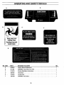
SAFETY RULES
_
CAUTION: ALWAYS DISCONNECT
SPARK PLUG WIRE AND PLACE WIRE WHERE IT
CANNOT CONTACT SPARK PLUG TO PREVENT ACCIDENTAL
STARTING WHEN SETTING UP, TRANSPORTING,
ADJUSTING
OR MAKING REPAIRS.
TRAINING
1. Carefully read this Owner's Manual
and anyother literature you may receive
before operating this equipment. Be
thoroughly familiar with the controls and
the proper use of the tiller and its.engine.
Know how to stop the unit and disengage
the controls quickly.
2. Never allowchildrento operatethe
tiller. Neverallowadults to operatethe
tiller without proper instruction.
3. Keepthe area of operation clear of all
persons, particularly children and pets.
Keep bystanders at least 25 feet from
area of operation.
engine, wait for all moving parts to come
to a complete stop, disconnect the spark
plug wire from the spark plug, and move
the wire away from the spark plug.
g. Do not operate this equipment if you
are under the influence of alcohol, medication,or when tired or ill.
PREPARATION
1. Thoroughly inspect the area where
the tiller is to be used and remove all foreign objects.
2. Be sure all control levers are released
andthe Wheel GearLever is in ENGAGE
before starting the engine.
3. Do not operate the tiller without wearing adequateouter garments. Avoid
loose garments or jewelry that could get
caught in moving parts of tiller or engine.
4. Keep in mind that the operator or user
is responsible for accidents or hazards
occurring to other people, their property,
and themselves.
5. Familiarizeyourself with all of the
safetyand operatingdecals on this"
equipifiedt and on any of its attachments
or accessories.
6. Do not run engine in an enclosedarea.
Engine exhaust containscarbon monoxide gas, a deadly poison that is odorless,
colorless, and tasteless. Do not operate
this equipmentnear buildings, windows,
or air conditioners.
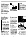
7. Do not allow hands or any other part
of the body or clothing near the rotating
tines or near any other moving part. The
tines begin to rotate backward once the
engine starts, and either the Forward
Clutch or the
ReverseClutch
Lever is engaged
(the Wheel Gear
Lever mustalways
be moved to ENGAGEbefore the
engine is started).
8. Before inspecting or servicing any
part of the equipment, shut off the
4. Do not operatethe tiller when barefoot
or wearing sandals,sneakers,or light
footwear. Wearprotectivefootwear that
will improve footing on slippery surfaces.
5. Do not till near underground electriccables, telephonelines, pipes or hoses. If in
doubt, contact your telephoneor utility
company.
6. Warning: Handlefuel with care; it is
highlyflammable and its vapors are explosive. Takethe following precautions:
a. Store fuel in containers specifically
designedfor this purpose.
b. The gas cap shall never be removed or fuel added while the engine is running. Allow the engine
to coo[ for several minutes before
adding fuel.
c. Keep matches, cigarettes, cigars,
pipes, open flames, and sparks
away from the fuel tank and fuel
container.
d. Fill fuel tank outdoors with extreme
care. Neverfill fuel tank indoors.
Use a funnel or spout to prevent
spillage.
e. Replaceall fuel tank and container
capssecurely.
f. If fuel is spilled, do not attempt to
start the engine,but move the
LOOK
FOR THIS SYMBOL
IT
MEANS-ATTENTIONH[
© Sears,
machine away from the area of
spillage and avoid creating any
source of ignition until fuel vapors
have dissipated.
7. Nevermake adjustmentswhen engine
is running (unless recommended by
manufacturer).
OPERATION
1. Do not put hands or feet near or under rotating parts.
2. Exerciseextreme caution when on or
crossing gravel drives, walks, or roads.
Stay alert for hidden hazardsor traffic.
Do not carry passengers.
3. After striking a foreign object, stop the
engine, disconnect the spark plug wire
and prevent it from touching the spark
plug, carefully inspect the tiller for any
damage, and repair the damage before
restarting and operatLngthe tiller.
4. Exercisecaution to avoid slipping or
falling.
5. If the unit should start to vibrate abnormally,stop the engine. Disconnectthe
spark plug wire and preventit from touching the spark plug, and check immediately
for the cause. Vibration is generally a
warning of trouble.
6. Stop the engine, disconnect the spark
plug wire and prevent it from touching
the spark plug whenever you leavethe
operating position, before unclogging the
tines, or when making any repairs, adjustments or inspections.
7. Takeall possible precautions when
leavingthe machine unattended. Stop the
engine. Disconnect spark plug wire and
move it away from the spark plug. Move
Wheel Gear Leverto ENGAGE.
8. Beforecleaning, repairing, or inspecting,stop the engine, and make certain all
moving parts havestopped. Disconnect
the spark plug wire and prevent it from
touching the spark plug to prevent accidental starting.
9. Always keepthe tiller tine hood flap
down.
TO
POINT ALERTIH
OUT IMPORTANT
SAFETY ISPRECAUTIONS.
BECOME
YOUR SAFETY
INVOLVED.
Roebuck and Co.
2
u
SAFETY RULES
10. Never use the tiller unlessproper
guards,plates,or other safetyprotective
devicesare in place.
11. Do not run engine in an enclosed
area. Engine exhaust contains carbon
monoxide gas, a deadly poison that is
odorless, colorless, and tasteless.
1;'. Keep childrenand pets away.
13. Never operatethe tiller under engine
power if the Wheel Gear Lever is in
DISENGAGE(FREEWHEEL).In this position, the wheels will not hold the tiller
back and the revolving tines could propel
the tiller rapidly backward, possibly causing loss of control. Always move the
Wheel Gear Lever to ENGAGEbefore
• starting the engine or engaging the
tines/wheels with the Forward Clutch or
the ReverseClutch.
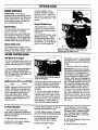
14. Be aware thatthe ti_lermay unexpectedly bounce upwardor jump backward if the tines should strike extremely
hard packed soil, frozen ground, or
buried obstacles like large stones, roots,
Qr stumps. If in doubt about the tilling
conditions, always use the following operating precautions to assist you in maintaining control of the tiller:
20. Use tiller attachments and accessories when recommended.
21. Neveroperatethe tiller without good
visibilityor light.
22. Neveroperatethe tiller if you aretired,
or under the influenceof alcohol, drugs or
medication.
23. Operatorsshall not tamper withthe
engine-governorsettings on the machine;
the governorcontrols the maximum safe
operatingspeedto protectthe engineand
all moving parts from damagecausedby
overspeed.Authorizedserviceshall be
sought ifa problemexists.
24. Do not touch engineparts which may
be hot from operation.Letpartscool down
sufficiently.
25. Pleaseremember:Youcan always
stop the tines and wheels by releasingthe
ForwardClutchLeveror the ReverseClutch
Lever(whicheverleveryou haveengaged)
or by moving the Throttle Control Leverto
STOP.
26. To load or unloadthe tiller, seetheinstructions in this Manual.
27. Use extremecaution whenreversing
or pulling themachinetowardsyou.
a. Walk behind and to one side of the
.,, tilier,,using one hand on the handlebars. Relaxyour arm, but use a
secure hand grip.
b. Use slower engine speeds.
c. Clearthe tilling area of all large
stones, roots and other debris.
d. Avoid using downward pressure on
handlebars. If need be, use slight
upward pressure to keepthe tines
..... from digging too deeply.
• e. In an emergency,stop tines and
wheels by releasingwhichever
Clutch Lever is engaged. Do not
attempt to restrain the tiller.
28. Start the enginecarefullyaccordingto
instructions and with feet well awayfrom
the tines.
15. Do not overload the tiller's capacity
by attemptingto till too deeplyat too fast
a rate.
3. Neverstore the tiller with fuel inthe fuel
tank insidea building where ignition
sourcesare present(such as hot water and
spaceheaters,furnaces, clothesdryers,
stoves,electricmotors, etc.). Allow engine
to cool beforestoring in any enclosure.
16. Never operatethe tiller at high transportspeeds on hard or slippery surfaces,
Lookbehindand usecarewhen backing
up.
17. Do not operatethe tiller on a slope
that is too steepfor safety. When on
slopes,slow downand makesure you
havegood footing. Never permitthetiller
to freewheel downslopes.
29. Neverpick upor carry a machinewhile
theengineis running.
MAINTENANCE/STORAGE
7. Never perform maintenancewhile the
engine is running or the spark plug wire is
connected, exceptwhen specifically instructed to do so.
8. If the fuel tank has to be drained, do
this outdoors.
TO AVOIDINJURY:
• READOWNER'SMANUAL.
• KNOW LOCATION AND
FUNCTION OF ALL CONTROLS.
• KEEPALL SAFETYDEVICES
AND SHIELDS IN PLACE
AND WORKING,
• NEVER ALLOW CHILDREN
ORUNINSTRUCTEDADULTS
TO OPERATETILLER.
• SHUT OFF ENGINE AND
DISCONNECTSPARKPLUG
WIRE BEFORE UNCLOGGING TINES OR MAKING
REPAIRS.
• KEEP BYSTANDERSAWAY
FROMMACHINE,
• KEEPAWAYFROM ROTATING PARTS.
• USE EXTREME CAUTION
WHEN REVERSING OR
PULLINGTHE MACHINETOWARDSYOU.
1. Keepthe tiller,attachments and accessories in safe workingcondition.
2. Checkall nuts, bolts, and screws at
frequent intervals for propertightness to
be sure the equipment is in safe working
condition.
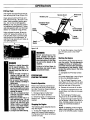
4. Toreducethe chancesof a fire hazard,
keepthe engine freeof grass,leaves,or
excessivegrease.
18. Neverallow bystandersnearthe
unit.
5. Storegasolinein a cool,well-ventilated area,safelyaway from anyspark-or
flame-producing equipment. Store gasolinein an approvedcontainer,safelyaway
from the reachof children.
19. Only useattachmentsand accessoriesthat are approvedby the tiller
manufacturer.
6. Refer to the Service and Adjustments
Section of this Manualif the tiller is to be
stored for an extendedperiod.
WARNING:
The engine exhaust from this
product contains chemica!s
knownto the State of Califormai
to cause cancer, birth defects, i
or otherreproductiveharm.
PRODUCT
SPECIFICATIONS
CONGRATULATIONS on your purchase of a Sears
Craftsman tiller. It has been designed, engineered and
manufactured to give you the best possible dependability
and performance.
Should you experience any problems you cannot easily
remedy,please contact your nearest Sears Service Center/Department. We have competent, well-trained technicians and the proper tools to service or repair this
machine.
Please read and retain this manual. The instructions will
help you assemble and maintain your machine properly.
Always observe the "SAFETY RULES."
HORSEPOWER:
8 HP
DISPLACEMENT:
19.43 CU. iN.
FUEL CAPACITY:
2 Quarts
SPARK PLUG (GAP 0.030-in.):
IGNITION:
Champion RJ-17LM*
or equivalent
Electronic
NET ENGINE WEIGHT:
50 LBS.
NET TILLER WEIGHT:
204 LBS.
• In Canada, replacespark plugwitha resistorplug.
MODEL NUMBER:
987.293330
SERIAL
NUMBER:
DATE OF
PURCHASE:
WARNING
THE MODELAND SERIAL NUMBERS WILL BE
FOUND ON A DECAL LOCATED ON THE TRANSMISSION OF YOUR MACHINE.
This machine is equipped with an internal combustion engine and should not be used on or near any
unimproved forest-covered, brush-covered or
grass-covered land unless the engine's exhaust
system is equipped with a spark arresfer meeting
applicable local or state laws (if any). If a spark
arrester is used, it should be maintained in
effective working order by the operator.
YOU SHOULD RECORD BOTH THE SERIAL NUMBER AND DATE OF PURCHASE AND KEEP IN A
SAFE PLACE FOR FUTURE REFERENCE.
In the state of California the above is required by
law (Section 4442 of the California Public
Resources Code). Other states may have similar
laws. Federal laws apply on federal lands. This
engine is not equipped with a spark arrestor for the
muffler.
Asparkarrester
for the muffler is
available through your nearest Sears authorized
service center. See the REPAIR PARTS section of
this manual.
MAINTENANCE
AGREEMENT
A Sears maintenance agreement is available on this
product. Contact your nearest Sears store for details.
CUSTOMER
RESPONSIBILITIES
O Read and observe the safety rules.
O Follow a regular schedule in maintaining, caring for
and using this product.
*,
[] Follow the instructions under "CUSTOMER
RESPONSIBILITIES" and "STORAGE" sections of
this manual.
LIMITEDTWO-YEARWARRANTYONCRAFTSMAN®
TILLER
Fortwo years from the date of purchase,when this Craftsman®Tiller is maintained, lubricated, and tuned up according to the
operating maintenance instructions in the owner's manual, Searswill repair,free of charge, any defect in material or
workmanship.
If this Craftsman®Tilleris used for commercialor rental purposes, this warrantyappliesfor only90 days from the date of
purchase.
THIS WARRANTYDOESNOT COVER:
• Expendableitems whichbecomeworn during normaluse, suchas tJQ.P,.(._,
belts,soarkglue, and air cleaner.
• Repairs necessarybecauseof operatorabuseor negligenceincludingbent crankshaftsand thefailureto maintain the
equipmentaccordingto the instructionscontainedin the owner'smanual.
WARRANTYSERVICEIS AVAILABLE
BYRETURNINGTHECRAFTSMAN@
TILLERTOTHENEARESTSEARSSERVICECENTERIN
THEUNITEDSTATES.THISWARRANTYAPPLIESONLYWHILETHISPRODUCTISIN USEIN THEUNITEDSTATES.
Thiswarrantygivesyou specificlegalrights,and you may also haveotherrightswhichvary from stateto state.
Sears, Roebuck and Co., D/817WA, Hoffman Estates, IL 60179
4
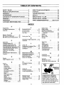
TABLE
OF CONTENTS
ii
SAFETY
RULES ...................................................
PRODUCT
WARRANTY
SPECIFICATIONS
..............................
..........................................................
ACCESSORIES
....................................................
CONTENTS
OF HARDWARE
PACKAGE
ASSEMBLY
...........................................................
2
SERVICE
4
STORAGE
4
TROUBLESHOOTING
6
DECALS
..............................................................
34
REPAIR
PARTS - TILLER
35
REPAIR
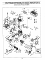
PARTS - ENGINE:
............ 7
8
OPEI_ATION
.......................................................
12
CUSTOMER
RESPONSIBILITIES
22
.....................
AND ADJUSTMENTS
........................
...........................................................
........................................
..................................
....................
PARTS ORDERING/SERVICE
26
32
33
............ 50
........... Back Cover
INDEX
A
Accessories ..................
Air Cleaner Maintenance
Assembly ....................
6
25
8
.......
B
Break-In Operation ...........
16
Belt Tension Adjustment .......
28
Belt Removal and Replacement , 30
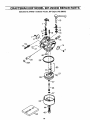
Carburetor ..................
Changing Engine Oil ..........
Changing Transmission Oil .....
Checking/Adding Engine Oil ....
Checking/Adding Transmission Oil
Checking/Adjusting Belt Tension.
Checking for Oil Leaks .........
Check List, Pre-Starting ........
Cleaning ....................
Cooling System Maintenance...
Controls ....................
25
24
24
24
24
28
23
15
25
25
12
D
Decals .....................
Depth Regulator Lever
Features/Controls
............
Forward Clutch .............
Forward Travel ...............
Fuel Tank ...................
34
........
14
E
Engine
Air Filter ..................
Carburetor ................
Choke Lever ...............
Cooling System ............
Fuel Tank .................
Oil, Checking/Adding ........
O_5_rat'ion.... _ ............
Parts .....................
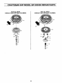
Recoil Start Rope ...........
Spark Plug ................
Speed ....................
Starting Engine .............
Stopping Engine ............
Storage ...................
Throttle Lever ...........
25
25
15
25
16
24
16
50
15
25
15
16
16
32
10,15
12
9,13
17
16
G
Guiding the Tiller .............
17
il
Handlebar Height Adjustment
Hardware ....................
C
S
F
Safety Rules .................
Safety Decals ...............
Seedbed Preparation ..........
Service Recommendation
Checklist .................
Slopes .....................
Spark Plug ..................
Starter Rope ................
Storage ....................
. .8,14
7
Leaks, Oil ...................
23
Loading and Unloading Tiller .... 21
Location of Controls ...........
12
Lubrication ..................
23
2
34
19
22
20
25
15
32
T
Tiller Parts ..................
Tilling ......................
Tilling Depths ................
Tine Cleaning ................
Tine Removal ................
Transmission Gear Oil .........
Troubleshooting ..............
Turning Around ..............
35
17
19
20
26
24
33
18
M
Maintenance Schedule ........
22
Maintenance Agreement ........
4
Model/Serial Number ...........
4
Motor Oil, Adding ..........
15, 24
Motor Oil, Changing ...........
24
0
Oil
......................
Off-Season Storage ...........
Operation ...................
15
32
17
II
Unpacking ...................
Untangling Tines .............
W
Warranty ....................
Wheel Gear Lever ............
Wheel Gear Cable Adjustment
Reverse Clutch ..............
Reverse Travel ..............
Recoil Starter Rope ...........
Repair Parts .................
5
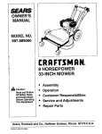
OPERATOR'S
POSITION
35
15
4
FORWARD
R
13
18
15
35
4
12
. .26
RIGHT
SIDE
P
Parts List ...................
Pre-Start Checklist ............
Product Specifications ..........
8
20
LEFT
SIDE
OPERATOR'S
POSITION
All references to LEFT and
RIGHT sides of the tiller are
given from the operator's position behind the handlebars (unless specified otherwise).
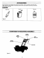
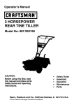
ACCESSORIES
These accessories were available when the tiller was purchased. They are available at most Sears retail
outlets, catalog and service centers. Most Sears stores can order repair parts for you when you provide the
model number of your tiller.
ACCESSORIES
Spark Plug
Motor Oil
GasCan
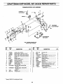
"'Figure 1-1
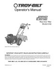
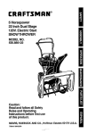
COMPONENTS REQUIRING ASSEMBLY
REVERSE
CLUTCH
ROD
ENGINE
WHEEL
LEVER
FORWARD
CLUTCHROD
HANDLEBARS
Figure 1-2
6
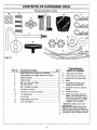
CONTENTS
OF HARDWARE PACK
Hardware
packed
in carton
10
©©
©©
2
Figure 1.3
T00LS/MATERIALS
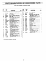
Ref. No,
Hardware Description
Qty.
NEEDED FOR ASSEMBLY
1
Height Adjustment Handle (for handlebar) ...........
1
(1)
* 3/8" open end wrench
2
Keyed Washer (for height adjustment handle) .....
1
(2)
* 9/16" open end wrenches
3
Plastic Tie Strap ...................................................
4
(1)
Scissors (to trim plastic ties)
4
Hairpin Cotter .......................................................
3
(1)
Ruler
5
6
3/8"-16 1" Hex Hd. Screw ....................................
3/8" Flat Washer ..................................................
2
2
(1)
Small Board (to tap plastic
knobs on control levers)
7
3/8"-16 Nylok Lock Nuts ......................................
Throttle Lever Knob .............................................
2
1
(1)
8
Automotive-type air pressure
gauge
9
#10-32 x 1/2" Round Hd. Screw
4
(1)
Clean Oil Funnel
10
#10 Lockwasher ...................................................
4
(1)
11
#10-32 Nut ...........................................................
4
12
Wheel Gear Lever Knob
1
13
5/16" Flat Washer ..................................................
Clean high-quality engine oil.
Refer to the assembly instructions in this manual for engine
oil specifications and quantity
required. Do not overfill.
..........................
......................................
1
• Adjustable wrenchesmay be used.
IMPORTANT:
Motor oil must be
added to the engine crankcase before the engine is started. Follow the
instructionsin the "Operation" section.
11,
7
ASSEMBLY
Read these instructions completely
before you attempt to assemble or
operate your new equipment. Your
tiller has been assembled at the factory with the exception of those parts
left'unassembled for shipping purposes. Steps in this section show
you how to assemble them. To ensure safe and proper operation of
your machine, all parts and hardware you install or adjust must be
tightened securely. Use the correct
tools as necessary to ensure proper
tightness.
UNPACKINGINSTRUCTIONS
• Inspect your machine immediately.
Be sure neither the carton nor contents have been damaged. If you
'.find or have reason to suspect
damage, contact the nearest
Sears Service Center for
assistance.
• Once the cardboard shipping carton is open, remove any packing
material from around the machine.
Remove any staples securing bottom of carton to wood pallet. Lift
.,off carton. Before disposing of the
carton or any of the packing materials, be sure to check them thoroughly for any small parts.
Leave unit on base of pallet during assembly steps (to safely remove unit from pallet, wait until
you have installed the handlebar
assembly and the Wheel Gear
Lever is placed in DISENGAGE).
The procedure for removing the
tiller is explained in Step 1, item 6
of these assembly steps.
• Also remove any packaging around
the handlebar.
• Perform the assembly on a clean,
level surface. If you need to move
the machine, be careful not to
severely bend any of the control
cables on the equipment.
• Remove the handlebar assembly
from the carton. Do not remove
the two control levers from the
' handlebars.
• A plastic bag inside the literature
envelope contains loose hardware.
Open the bag and check the contents against the hardware list on
Page 7 and the hardware shown in
Figure 1-3.
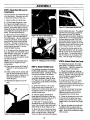
ASSEMBLYSTEPS
STEP 1: Attach the Handlebars
1. Remove the Reverse Clutch
Lever (B, Figure 2-1) from the handlebars (A). Remove any rubber
bands from the handlebars.
2. Position the handlebar crossbrace (C, Figure 2-2) in front of the
curved height adjustment bracket (D)
and place the handlebar ends to the
outside of the two mounting tabs on
top of the transmission.
Figure2.1: RemoveReverseClutchLever.
3, Attach the handlebars to the
mounting tabs with two 3/8-16 x 1"
screws (heads of screws go to inside
of tabs), 3/8" flat washers and 3/8"16 Nylok lock nuts (see Figure 2-2).
Do not fully tighten the screws at this
time.
4. Move the handlebar to align the
hole in the cross-brace with one of
the four slots in the curved height
adjustment bracket. Place the keyed
washer (E, Figure 2-3) on the height
adjustment handle (F) with the
raised keys (edges) on the keyed
washer facing down.
5. Screw the height adjustment handle (F) into the threaded hole in the
handlebar cross-brace, making sure
that the raised keys on the washer fit
into the selected slot on the curved
bracket. Tighten the height adjustment handle securely. Next, securely tighten the two screws that attach
the handlebar ends to the mounting
tabs (Figure 2-2).
6. To remove the tiller from its shipping platform, free the wheels by
moving the Wheel Gear Lever (G,
Figure 2-4) to the DISENGAGE position (this allows the wheels to rotate). Carefully unwrap the wheel
gear cable from around the unit before moving the lever. Use this DISENGAGE mode only when the engine is not running. Before starting
the engine, the Wheel Gear Lever
must be placed in the ENGAGE position (see the "Operation" section
for details).
D
Figure2-2: Attachhandlebars.,
E F
Figure2-3: Installheightadjustment
handle.
Figure2-4: Put WheelGearLeverIn
DISENGAGE
position.
ASSEMBLY
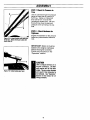
STEP2: Attach ReverseClutch
Lever
1. Slide the Reverse Clutch Lever
(removed in Step 1) down through
the hole in the left side of the handlebar control panel and pass it above
the cross-brace at the lower end of
the handlebar.
2. Insert the end of the lever (I, Figure 2-5) through the hole in the pivot
(J). Note that there are two small
holes in the lower end of the lever.
3. Install a 5/16" flat washer (K) and
secure it with a hairpin cotter (L)
through the bottom hole in the lever.
match with the numbered slot in the
height adjustment bracket. For example, if the handlebar is set in slot
#1, then the Forward Clutch rod
must be installed in hole #1 of the
clutch swivel plate.
IMPORTANT: Whenever the handlebar height is changed, the hole position of the Forward Clutch rod must
be changed accordingly. Changing
the handlebar height changes the
tension on the Forward Clutch rod this tension must be adjusted by
relocating the rod in the appropriate
hole in the clutch swivel plate.
4. Select the proper hole in the
clutch swivel plate and insert the
Forward Clutch rod so that the tip
faces inward (see Figure 2-7). Secure the rod by inserting a second
hairpin cotter through the hole near
the tip of the rod.
5. Check for correct tension on the
Forward Clutch rod as follows:
cure it with the hairpin cotter,
and repeat Steps 5a and 5b.
If the gap is less than 3/16",
rotate the rod clockwise (as
viewed from the front of tiller)
to increase the gap. Reinstall
the rod in the correct clutch
swivel plate hole, secure it
with the hairpin cotter, and repeat Steps 5a and 5b.
Figure2-6: Install ForwardClutchrod.
(a) There are two interconnected
Forward Clutch paddles that
hang beneath the control panel.
Lift and hold the right-side paddle
against the handlebar grip.
Figure2-5: InstaNReverseClutchLever.
IMPORTANT: If the handlebar is adjusted to the highest position, then
the bottq_mof the Reverse Clutch
Lever must be secured with the hairpin cotter (L) through the top hole in
the lever. Simply remove the hairpin
cotter, slide the washer (K) up the
lever, and replace the hairpin cotter.
STEP3: Attach ForwardClutchRod
1. The upper end of the Forward
Clutch rod is attached to the bottom
of the handlebar control panel. Turn
the rod (M, Figure 2-6) so the small
bend at its lower end points inward.
2. Insert a hairpin cotter down
through the hole located closest to
the bend (see Figure 2-6).
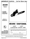
3. There are four numbered holes in
the i_ldtchswivel plate (see Figure 27) and four numbered slots in the
curved height adjustment bracket.
For correct operation of the Forward
Clutch rod, the numbered hole used
for the Forward Clutch rod must
(b) While squeezing the paddle,
measure the gap between the Ering and the lower end of the
clutch rod bracket (see Figure 28). The gap should be 3/16"-to5/16". NOTE: A stack of 5 pennies is approximately 5/16" thick.
(c) If the gap is incorrect:
(1) First check that the Forward
Clutch rod is in the correct
hole in the clutch swivel plate.
If not, reposition the rod and
repeat Step 5b.
Figure2-7: Numbered
settingsforhandlebarheightslotsandclutchswivelplate
holes.
(2) If the Forward Clutch rod is in
the correct hole and the gap is
incorrect, you will need to adjust the length of the Forward
Clutch rod. To do this, first release the Forward Clutch paddle and then disconnect the
rod from the clutch swivel
plate (remove hairpin cotter at
end of rod and pull rod out of
hole in clutch swivel plate).
If the gap is more than 5/16",
rotate the rod counterclockwise (as viewed from the front
of tiller) to decrease the gap.
Reinstall the rod in the correct
clutch swivel plate hole, se9
Gap shouldbej
3/16"-to-5/'16"
Figure2-8. Whilesqueezing
Forward
Clutchpaddle,measuregapbetweenend
of bracketandE.ring.
ASSEMBLY
STEP4: CheckGearOil Levelin
TranS'm[ssion
The transmission was filled with gear
oil at the factory. However, be sure
to check the oil level at this time.
1. Move the tiller to a level area.
2. Pull the Depth Regulator Lever
(N, Figure 2-9) straight back and
then slide it to the second notch from
the top. If the lever does not move
freely, lift the tine hood flap and look
for a plastic tie securing the lever in
place. Cut and remove the tie.
3. Remove the oil level check plug
(O, Figure 2-10) on the left-side of
the transmission. (Due to dried paint
on the plug threads, it may require
some force to remove the plug the
first time.) The gear oil level is correct if oil starts to flow out of the hole
as the plug is removed. If so, securely reinstall the plug.
4. If oil does not flow from the check
hole, add SAE 140, SAE 85W-140 or
SAE 80W-90 weight gear oil (preferably use API rated GL-4 gear oil,
however GL-5 can be used for small
top-offs) as follows:
NOTE: Do not use automatic transmission fluid or engine oil in the
transmission.
(a) Clean area around oil fill hole (P,
,,.Figure, 2-11 ) and unscrew oil fill
plug.
(b) Using a clean funnel, slowly add
gear oil until it flows from the oil
level check hole (O, Figure 2-10).
Securely reinstall the oil level
check plug (O).
(c) Reinstall and tighten the oil fill
plug.
Figure2.12:Attachenginethrottlelever.
Figure2.10: Gearoillevelcheckplug.
Figure2-11: Addinggearoilin o/Ifill hole.
STEP6: AttachWheel GearLever
STEP5: Attach Throttle Lever
For shipping purposes, the wheel
gear cable is wrapped around the
transmission. Carefully unwrap the
cable and attach it as follows:
For shipping purposes, the engine
throttle cable assembly is wrapped
around the engine. Carefully unwrap
the cable and attach it as follows:
1. Route the throttle cable up the
right-side handlebar. Insert its lever
(R, Figure 2-12) up through the slot
in the control panel labeled "ENGINE
THROTTLE."
2. Insert two #10-32 x 1/2" round
head screws down through the "+"
marks on the control panel decal and
through the holes in the base of the
engine throttle lever.
3. Hold the engine throttle lever
base against the bottom of the control panel and secure it with two #10
Iockwashers and #10-32 nuts.
4. Place the "T" shaped engine
throttle lever knob on the end of the
lever. Use a board to tap knob until it
seats firmly on lever (Figure 2-12).
Figure2.9: PutleverIn secondnotch.
which catches the lever. This detent
prevents the lever from unintentionally moving to the STOP setting
when you are just trying to slow the
engine down.) If the lever is difficult
to move away from the STOP setting, loosen both screws and move
the lever assembly slightly to the left.
Retighten screws and recheck movement. Adjust the lever as needed.
6. Secure the throttle cable to the
right-side handlebar with two plastic
ties (S, Figure 2-13) located about
two feet apart. The serrated side of
the tie must be on the inside of the
loop. Trim tie length with scissors.
5. Move the lever forward and backward - it should move freely through
the full range of travel. (Note that
there is a detent at the SLOW setting
10
1. Route the wheel gear cable up
the left-side handlebar and insert the
lever (T, Figure 2-14) up through the
slot in the control panel that is labeled "WHEEL GEAR."
2. Insert two #10-32 x 1/2" round
head screws down through the "+"
marks on the control panel decal and
through the holes in the base of the
wheel gear lever.
'....
3. Hold the wheel gear lever base
against the bottom of the control
panel and secure it with two #10
Iockwashers and #10-32 nuts.
4. Place the wheel gear lever knob
on the end of the lever and use a
board to tap the knob down until it
seats firmly on the lever (see Figure
2-14).
5. Secure the cable to the left-side
handlebar with two plastic ties (U,
Figure 2-13) located about two feet
apart. Snip off any excess tie length
with scissors.
,,
ASSEMBLY
STEP7: CheckAir Pressurein
Tires
S
Use an automotive-type tire pressure
gauge to check the air pressure in
both tires. Deflate or inflate both
tires evenly from 15-to-20 PSI
(pounds per square inch). Be sure
that both tires have the same air
pressure or the unit witl pull to one
side.
STEP8 : CheckHardwarefor
Tightness
.Figure2.13. Attach throttle cable with plastic ties (S). Attach wheel gear cable with
plastic ties (U).
Inspect the hardware on the unit and
tighten any loose screws, bolts and
nuts.
IMPORTANT" Motor oil must be
added to the engine crankcase
before the engine is started.
Follow the instructions in the
"Operation" section.
CAUTION
Figure2-14: Attachwheelgearlever.
Unit is shipped without oil in
engine crankcase. DO NOT
start engine until oll has been
added. Severe engine damage
will result if this instruction is
net followed. See "Operation"
Section in this manual for oil
filling procedure.
11
OPERATION
KNOWYOURTILLER
READ THIS OWNER'S MANUALAND ALL SAFETY RULES BEFORE OPERATING THIS EQUIPMENT.
cation and function of all features and controls on the equipment. Save this manual for future reference.
Know the lo-
ReverseClutch
Wheel G'ear
_Lever
MEETS ANSI B71.8 - 1996
SAFETY STANDARD
This machine meets voluntary safety
standard B71.8 - 1996, which is
sponsored by the Outdoor Power
Equipment Institute, Inc., and is published by the American National
Standards Institute, Inc.
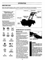
Operating Symbols
Varioussymbols are used on the tiller
to indicatecontrolsettings(your model
may not have all of the symbols).
These symbols are shown below with
a descriptionof theirmeaning.
FAST
SLOW
CHOKE
Handlebar Height
Adjustment
ChokeControl
ForwardClutch
(on eachside)
Recoil
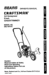
LOCATION
ANDUSEOFTILLERCONTROLS
Wheel GearLever
This lever (A, Figure 3-1) has two
operating positions: ENGAGE and
DISENGAGE.
ENGINE
STOP
ENGINE
START
ENGINE
RUN
z2.r
ENGAGE
ROTATING
TINES
ip,
DISENGAGE
TILLER
DIRECTION
o--->
STOP
..... N
NEUTRAL
LEVER
DIRECTION
R
REVERSE
In the ENGAGE position, the wheels
will start turning when either the
Forward Clutch or the Reverse
Clutch is engaged (the tines will also
start turning when either clutch is
engaged).
The DISENGAGE position places
the wheels in the freewheeling mode
to allow the unit to be moved without
the engine running. Use the DISENGAGE position only when the engine
is not running. See "DANGER"
statement that follows.
To shift to ENGAGE, gently (do not
force) move the lever forward while
also rolling the tiller a few inches forward or backward. (Moving the tiller
helps to align the shift mechanism
with the transmission wheel drive
gears.) The wheels will not freewheel when the lever is properly set
in the ENGAGE position.
To shift to DISENGAGE (freewheel)
simply move the lever, rearward,
without rolling the tiller. The wheels
will roll freely when the lever is properly set in the DISENGAGE position.
12
Figure3-1: WheelGearLever.
DANGER
Never place the Wheel Gear
Lever in DISENGAGE (Freewheel) when the engine is running.
Having the Wheel Gear Lever
in DISENGAGE and then engaging the tines/wheels with
either the Forward Clutch or
the Reverse Clutch could allow
the tines to propel the tiller
rapidly backward.
Failure to follow this instruction could result in personal
injury or property damage:
' '
OPERATION
ForwardClutch
The two interconnected levers (B,
Figure 3-2) control the engagement
of forward drive to the wheels and
power to the tines.
To Operatethe ForwardClutch:
1, Before engaging the Forward
Clutch, put the Wheel Gear Lever in
the ENGAGE position (sea "WARNING" below).
2_, Lift and hold one or both of the
levers against the handlebar grips to
engage the wheels and tines.
3. Release BOTH levers to disengage the wheels and tines. All forward motion will stop (the engine will
continue to run).
IMPORTANT: The Forward Clutch
Levers are connected to a mechanical interlock feature that automatically shifts the separate Wheel Gear
Lever (A, Figure 3-1) into ENGAGE
position when either of the Forward
Clutch Levers is lifted up against the
handlebars to engage power to the
wheels and tines. This is a safety
feature designed to prevent the
wheels from being in DISENGAGE
(freewheel) position when the tines
are rotating.
Before starting the engine, test
the function of the mechanical interlock as follows:
.
WARNING
Never engage the wheels and
tines with the Forward Clutch
or the Reverse Clutch unless
the Wheel Gear Lever is in
ENGAGE.
o
Engaging the Forward Clutch
or the Reverse Clutch when the
wheels are not engaged could
allow the tines to rapidly prope] the tiller
forward or
backward.
Failure to follow this warning
could result in personal injury
or property damage.
.
Put the Wheel Gear Lever in
the DISENGAGE position and
roll the tiller back and forth a
few inches. The wheels
should roll freely.
At rest, squeeze either of the
Forward Clutch Levers ("paddles") against the handlebar
grips. As the "paddles" move
upward, the mechanical interlock will automatically move
the Wheel Gear Lever forward
into the ENGAGE position.
(Roll the tiller back and forth a
few inches.) If it does, the tiller
wheels will not roll freely when
you push and pull on the handlebars.
The mechanical interlock is
working properly if it performed
as described in step 2. If the
mechanical interlock did not
perform correctly, do not operate the tiller until it has been
inspected and corrected by
your Sears Service Center.
ReverseClutch
This lever (C, Figure 3-3) controls
the engagement of reverse drive to
the wheels and tines. It is the only
control that provides reverse direction of the wheels and tines.
To Operatethe Reverse Clutch:
1. Before engaging the Reverse
Clutch, put the Wheel Gear Lever in
ENGAGE (see "WARNING" statement on this page).
2. Release the Forward Clutch
levers.
3. To move the tiller in reverse, first
stop all forward motion. Then lift up
the handlebars until the tines clear
the ground and pull the Reverse
Clutch lever out. The tines and
wheels will rotate in a reverse direction as long as the lever is held in
REVERSE. To stop the wheel'S;_.nd'
tines, release the lever and it will return to NEUTRAL. Never attempt to
till while going in the reverse
direction.
WARNING
• Use extreme caution when
reversing or pulling the machine toward you. Lookbehind to avoid obstacles,
• Never attempt
reverse.
to till
Failure to follow this warning
could result in personal injury
or property damage.
B
Figure3-3".ReverseClutchlever.
Figure3-2".ForwardClutchlevers.
13
in
OPERATION
DepthRegulator
WARNING
This lever (D, Figure 3-4) controls
the tilling depth of the tines. Pull the
lever straight back and slide it up or
down to engage the notched height
settings.
The highest notch (lever all the way
down) raises the tines approximately
1-1/2 inches off the ground. This
"travel" position allows the tiller to be
moved without the tines digging into
the ground.
Moving the lever up increases the
tilling depth. The lowest notch allows a tilling depth of approximately
six to eight inches, depending on soil
conditions.
Always place the Depth Regulator Lever in the "travel"
position before starting the engine. This position prevents
the tines from touching the
ground until you are ready to
begin tilling.
Figure3.4: DepthRegulatorLever.
Failure to follow this warning
could result in personal injury
or property damage.
later is found in the "Operation" Section of this manual.
F_)r best results, always begin tilling
at a shallow depth setting, then increase the tilling depth. Further information on using the Depth Regu-
HandlebarHeightAdjustment
To Adjustthe Handlebar Height:
The handlebar height is adjustable to
four different settings. Set the handlebar height to a comfortable setting, but keep in mind that the handlebar will be lower when the tines
are engaged in the soil.
1. Stop the engine, wait for all parts
to stop moving and then disconnect
the spark plug wire.
WARNING
Whenever
the handlebar
height is changed, the Forward
Clutch shift mechanism must
be readjusted.
When adjusting or checking
the Forward Clutch mechanism, shut engine off, disconnect spark plug wire and prevent it from touching the spark
plug.
Failure to follow this warning
could allow the Forward Clutch
mechanism to operate improperly which could result in personal injury or property
damage.
IMPORTANT: If the handlebar is adjusted to the highest position, then
the bottom of the Reverse Clutch
Lever must be secured with the hairpin cotter (and washer) through the
top hole in the lever (see K and L) in
Figure 2-5, Page 9.
,.,
2. Loosen the two screws at the
lower ends of the handlebar.
3. Loosen the height adjustment
handle (E, Figure 3-5) and pull the
keyed washer (F) free of the slots in
the curved height adjustment bracket.
4. Move the handlebars to the new
slot setting and insert the raised
keys on the keyed washer into the
slot. nghten the height adjustment
handle securely.
Figure3.5: HeightAdjustinghandle(E).
5. Retighten the two screws at the
ends of the handlebar.
6. Adjust the tension on the Forward
Clutch rod shift mechanism, as follows:
(a) Remove the inner hair pin cotter
from the end of the Forward
Clutch rod.
(b) There are four numbered holes in
the clutch swivel plate (see Figure 3-6) and four numbered slots
in the curved height adjustment
bracket. For correct operation of
the Forward Clutch mechanism,
the numbered hole used for the
Forward Clutch rod must match
the numbered slot in the height
adjustment bracket. Example: If
handlebar is in slot #4, put Forward Clutch rod in hole #4 of
clutch swivel plate.
14
Figure3.6: Handlebar height slatsand
clutchswivulplate holes.
(c) Select the correct hole in the
clutch swivel plate and insert the
Forward Clutch rod (tip faces inward). Secure the rod with the
hairpin cotter.
(d) Check for correct tension on the
Forward Clutch rod as described
in Step 5 of "Step 3: Attach Forward Clutch Rod" on page 9.
OPERATION
ENGINECONTROLS
IMPORTANT: The engine is
equipped with a recoil starter, a handlebar-mounted engine throttle lever,
and a choke control The locations
and functions of each of these controls are described below.
are three settings: FULL
CHOKE, PARTIAL CHOKE
and NO CHOKE. Detailed instructions for using the choke
lever are provided later in this
section.
EngineThrottle Lever
RecoilStarter
The recoil starter (G, Figure 3-7) is
used to "pull-start" the engine.
Before pulling the recoil starter handle, make sure there are no obstacles behind you. See "Engine Starting and Stopping" in this section for
detailed engine starting instructions.
Engine Choke Lever
The throttle lever (I, Inset to
Figure 3-7) is used to adjust
engine speed as well as stop
the engine.
Use the START position when
starting the engine. Use the
SLOW position when idling
the engine. Pull the lever all
the way back to the STOP position to turn the engine off.
The choke lever (H, Figure 3-7) allows a richer air/gas mixture to make
starting a cold engine easier. There
Figure3-7:Enginecontrols--RecoilStarter(G);
ThrottleLever(H); ChokeLever(I).
BEFORE
STARTING
ENGINE
AddMot_)r011to Engine
the dipstick so as to avoid overfilling
the engine with oil. ALWAYS MAINTAIN THE OIL LEVEL AT THE FULL
MARK.
The tiller is shipped without oil in the
engine. Permanent engine damage
will result if the engine is run without
oil.
1. Only use high quality detergent oil
with API service classification SF,
SG, SH, or SH/CD. Above 32OF, use
SAE 30; below 320F, use 5W30. Do
nat.use SAE 10W40 oil
)
,
4. Securely replace the oil dipstick.
Figure3-8:Addmotoroil totheengineus.
ingtheoilfill tube(J).
2. With the tiller on level ground, pull
32OF-.-----.._
I
SAE30 warmer]
) ]/ the Depth Regulator Lever (Figure
3-4) back and then all the way up
until the lowest notch in the lever is
NOTE: Although multi-viscosity oils
(5W30, 10W30, etc.) improve startengaged.
ing in cold weather, these oils will re3. Unscrew the engine oil dipstick
sult in increased oil consumption
(J, Figure 3-8) from the oil fill tube.
when used above 32OF. Check
Using a clean funnel, slowly add oil
engine oil more frequently to avoid
into the oil fill tube until the oil level
possible engine damage from runreaches the FULL mark reading on
ning low on oil.
the oil dipstick. While adding oil,
check the level several times with
[ colder.._----._5W30
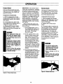
Pre-Start Checklist
Move the tiller to a level area,
then make the following checks and
perform the following services before
starting the engine.
3. Check the Air Cleaner. It must be
securely assembled and clean.
4. Check Safety Guards. All guards
and covers must be fastened securely.
1. Disconnect Spark Plug Wire.
5. Check Engine Cooling System.
The cooling fins and air intake
screen must be clear of debris.
2. Add motor oil to engine. (Refer to
instructions on this page.)
6. Adjust Handlebar Height.
15
IMPORTANT: Experience indicates
that alcohol-blended fuels (gasohol or
using ethanol or methanol) can attract moisture which leads to separation and formation of acids during
storage. Acidic gas can dama_j_ the '
fuel system of an engine while in storage. To avoid problems, the fuel system should be emptied before storage for 30 days or longer. Drain the
gas tank, start the engine and let it
run until the fuel lines and carburetor
are empty. Use fresh fuel next season. See STORAGE instructions for
additional information. Never use engine or carburetor cleaner products in
the fuel tank or permanent damage
may occur.
7, Put Gasoline in the Fuel Tank..
(Refer to instructions on next page.)
Use fresh, clean, unleaded regular
fuel. Fuel goes stale if stored for
more than six months. Do Not Mix
Oil With Gasoline!
8. Put Depth Regulator Lever in the
"travel" position.
9. Reconnect Spark Plug Wire.
OPERATION
Fill Fuel Tank
The engine must be off and cool before removing fuel fill cap (Figure 3-9).
Clean area around fuel fill cap and
then remove fill cap. Be sure to use
clean, fresh unleaded regular gasoline. Do not mix oil with gasoline.
NOTE: Do not use gasoline containing methanol (wood alcohol). Never
use stale gasoline left over from last
season or unused for long periods.
Using a funnel or spout, fill tank to
within 1/2" below the bottom of the
fuel tank filler neck to prevent spills
and to allow for fuel expansion. Install the fill cap securely and wipe up
any spilled gasoline.
Wheel Gear
Reverse Clutch
ThrottleLever
J
Lever
Handlebar Height
Adjustment
Choke
Control
ForwardClutch
(on each side)
Depth
Regulator
Recoil
Starter
Figure3-I0
WARNING
Figure3-9: Fill the fuel lank (K).
DANGER
Gasoline is highly flammable
and its vapors explosive. Follow these safety practices to
prevent injury from fire or explosion:
• Never fill tank if engine is
running or hot from use. Let
engine and mufflercool down
beforerefueling.
• Do not permit open flames,
.sparks,matchesor smokingin
fueling area.
• Fill fuel tank outdoors in a
well-ventilated area. Wipe
up any fuel spills and move
tiller away from fumes before
startingthe engine.
• Use only an approved fuel
container and lock it safely
away from children.
• Store fuel and the tiller in a
well-ventilated area. Do not
store fuel or tiller where fuel
vapors may reach an open
flame or spark, or an ignition
source (a hot water heater,
furnace, clothes dryer, electric motor, or the like).
• Let enginecoolbeforestoring.
Before operating your machine, carefully read and understand all Safety and Operation instructions in this Manual and on the decals on the
machine.
Failure to .follow these instructions can result in serious personal injury.
STOPPINGAND
STARTING
THEENGINE
Break-InOperation
Perform the following maintenance
during the first hours of new operation (see "Customer Responsibilities"
section of this manual).
1. Change engine oil after first 2
hours of new engine operation.
2. Check for loose or missing hardware on unit. Tighten or replace as
needed.
Stoppingthe Engine
The following steps describe how to
stop the engine.
1. To stop the wheels and tines, release the Forward Clutch levers or
the Reverse Clutch lever (whichever
control is in use).
16
2. To stop the engine, move the Engine Throttle Lever to the STOP
position.
Startingthe Engine
The following steps describe how to
start the engine. Do not attempt to
engage the tines or wheels until
you have read all of the operating
instructions in this Section. Also
review the safety rules in the Safety Section.
1. Complete the '?re-Start Checklist".
2. Put the Wheel Gear Lever (Figure
3-10) in the ENGAGE position.
3. Put the Depth Regulator Lever
(see Figure 3-10) in the "travel" position (lever all the way down) so that
the tines are clear of the ground.
4. Release all controls on the tiller.
5. If engine is equipped with a fuel
shutoff valve, turn valve to the open
position.
6. Put the Engine Throttle Lever
(Figure 3-10) in the START setting.
7. Choke the engine (see Figure 310) as follows: Move choke lever to
FULL CHOKE position (move in direction of arrowhead located on
lever).
NOTE: If restarting a warm engine
after a short shutdown, move choke
lever to NO CHOKE position instead.
i,
OPERATION
CAUTION
To help prevent serious
personal injury or damage to
equipment:
• Before starting engine, put
Wheel Gear Lever in ENGAGE
position.
• Before starting engine, put
ForwardClutchLeversand Reverse Clutch Lever in neutral
(disengaged)positions by releasinglevers.
• Never mn engine indoorsor in
enclosed,poorlyventilatedareas. Engine exhaust contains
carbon monoxide, an odorless,colorlessanddeadlygas.
• Avoid engine muffler and
nearby areas. Temperatures
in these areas may exceed
150o1.
then to NO CHOKE position. If
engine falters, move choke
lever to 1/2 CHOKE until engine runs smoothly and then to
NO CHOKE position.
NOTE: If engine fails to start after 3
pulls, move choke lever to NO
CHOKE position and pull starter rope
again.
NOTE: If engine fires, but does not
continue to run, move choke lever to
FULL CHOKE and repeat instructions "a", "b", and "c" until engine
starts.
OPERATINGTHETILLER
The following pages provide guidelines to using your tiller effectively
and safely in various gardening applications. Be sure to read "Tilling
Tips & Techniques" in this Section
before you actually put the tines into
the soil.
DANGER
GASOLINE
IS
HIGHLY
FLAMMABLE AND ITS VAPORS ARE EXPLOSIVE.
Follow gasolinesafety rules in
this manual (see Safety Section).
Failure to follow gasoline
safety instructions can result
in serious personal injury
and property damage.
8. Pull recoil starter rope, as follows:
(a) Check behind you before
pulling the recoil starter handle.
Avoid contacting any obstacles
when pulling the handle. Place
one hand on the fuel tank to
....'stabilize
the) unit when you pull
the starter handle.
(b) Pull recoil handle until you feel
resistance. Let rope rewind fully. Then pull rope out rapidly.
Maintain control of rope so it
slowly returns into starter
mechanism. This action may
need to be repeated several
times until the engine starts.
(c) When engine starts, gradually
move choke lever (on engines
so equipped) to 1/2 CHOKE until engine runs smoothly and
WARNING
3. Start the engine and allow it to
warm up. When warm, put throttle
control in fast speed setting.
4. For forward motion of the wheels
and tines:
(a) Pull the Forward Clutch lever
"paddles" up and hold them
against the handlebars. To
stop forward motion of the
wheels and tines, release the
"paddles."
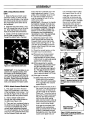
(b) As the tilter moves forward, relax and let the wheels pull the
unit along while the tines dig.
Walk behind and a little to one
side of the tiller. Use a light but
secure grip with one hand on
the handlebars, but keep your
arm loose. See Figure 3-11.
Let the tiller move ahead at its
own pace and do not push
down on the handlebars to try
and force the tiller to dig deeper
- this takes weight off the
wheels, reduces traction, and
causes the tines to try and propel the tiller.
Keep away Irom rotating tines.
Rotating tines will cause serious personal injury.
1. Follow the "Pre-Start Checklist"
on Page 15. Be sure the Wheel
Gear Lever is in the ENGAGE
position.
2. Put the Depth Regulator
Lever in the '_traver' position (lever all the way
down) so that the tines are
clear of the ground. Use
this position when practicing with your tiller or when
moving to or from the garden. When you are ready
to begin tilling, you must
move the Depth Regulator
Lever to the desired depth
setting (see "Tilling Tips &
Techniques").
Figure3-11: Useonehandtoguidetiller when
moving
17
OPERATION
5. For reverse motion of the tiller
(tines and wheels):
(a) Look behind and exercise caution when operating in reverse.
Do not till while in reverse.
(b) Stop all forward motion before
reversing. Lift the handlebars
with one hand until the tines
are off the ground and then pull
the Reverse Clutch lever out to
....engage reverse motion (see
, Figure 3-12). To stop reverse
motion, let go of the Reverse
Clutch lever.
6. To Turn the Tiller Around:
(a) Practice turning the tiller in a
level, open area. Be very careful to keep your feet and legs
away from the tines.
(b) To make a turn, reduce the engine speed and then lift the
handlebars until the engine and
tines are balanced over the
wheels (Figure 3-13).
(c) With the tiller balanced, push
sideways on the handlebar to
move the tiller in the direction of
the turn (Figure 3-14). After
completing the turn, slowly lower the tines into the soil and increase the engine speed.
Figure3-12: Raisetinesoffgroundand
lookbehindwhenmovingin reverse.
Turningthe Tiller Around
Stoppingthe Tiller and Engine
1. To stop the wheels and tines, release the Forward Clutch "paddles"
or the Reverse Clutch Lever
(whichever is engaged).
2, To stop the engine, move the
Engine Throttle Lever to STOP.
Figure3-13: Tobeginturn, reduceenginespeedandlift handlebareuntilengineandtines
arebalancedoverwheels.
18
Figure3-14: Withtiller bal.
ancedoverwheels(andtines
outof theground),pushhandlebarssidewaystoturntiller.
OPERATION
Tilling Tips & Techniques
Let the tiller do the work
• While tiUing, relax and let the wheels
pull the tiller along whilethe tines do
the digging. Walk on the side that is
' notyet finished (to avoid making footprints in the freshly tilled soil) and
lightly, but securely grip the handlebar
with just one hand. See Figure 3-11.
• Avoid the temptation to push down on
the handlebars in an attempt to force
the tiller to dig deeper. Pushing down
on the handlebarstakes the weight off
the poweredwheels,causingthem to
lose traction. Without the wheels helping to hold the tiller back, the tines will
attempt to propel the tiller- causing
the _iller to move rapidly back toward
you. (Sometimes, slight downward
pressure on the handlebarswill help
get through a particularly tough section
of sod or unbroken ground, but in
most casesthis won't be necessary at
all.)
Tilling depths
• This is a CRT (counter-rotating tine)
tiller. As the wheels pull forward, the
tines rotate backward. This createsan
"uppercut" tine action which digs
deeply, uprooting soil and weeds.
Don't overload the engine, but dig as
deeplyas possible on each pass. On
later passes, the wheels may tend to
spinin the soft dirt. Help them along
by lifting slightly on the handlebar (using just one hand, palm upward, works
most easily).
• Watering the garden area a few days
prior to tilling will maketiltingeasier,as
will letting the newly worked soil rest
for a day or two before making a final,
deep tilling pass.
• When cultivating (breaking up the surface soil around plantsto help destroy
weeds), adjust the tines to dig only 1U2" to 2"deep. Using shallow tilling
depths helps preventInjury to plants
whoseroots often grow close to thesurface. If needed,lift up on the handlebars
slightlyto preventthe tinesfrom digging
too deeply. Cultivatingon a regular basis
not only eliminatesweeds,it also loosens
and aeratesthe soil for better moisture
absorptionand fasterplant growth.)
.....
Avoidtilling soggy, wet soil
Tillingwet soil often results in large,
hard clumps of soil that can interfere
with planting. If time permits, wait a
day or two after heavy rains to allow
the soil to dry before tilling. Testsoil
by squeezing it into a ball. If it compresses too easily, it is too wet to till.
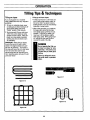
Avoidmakingfootprints
With planning, you can allow enough
room between rows to cultivate (see
Figure3-18). Leave room for the hood
width, plus enough extra room for future piant growth.
Clearingthe tines
Thetines have a self-clearingaction
whicheliminates most tangling of debris
in the tines. However, occasionally dry
grass, stringy stalks or tough vines may
becometangled. Follow these procedures to help avoid tangling and to clean
the tines, if necessary.
• Whenever possible, walk on the untilled
side of the unit to avoid making footprints in your freshly tiltedor cultivated
soil. Footprints cause soil compaction
that can hamper root penetration and
• To reduce tangling, set the depth regucontribute to soil erosion. They can
lator deep enough to get maximum
also "plant" unwanted weedseeds back
"chopping" action as the tines chop the
into the freshly tilled ground.
material against the ground. Also, try
to till under crop residues or cover
crops while they are green, moist and
Choosingcorrectwheel
tender.
and tine speed
With experience,you will find the "just
right" tilling depth and tilling speedcombination that is best for your garden.
• While power composting, try swaying
the handlebarsfrom side to side (about
6"to 12"). This "fishtaiting" action of.
ten clears the tines of debris.
Set the engine throttle lever at a speedto
• If the procedures above don't clear the
give the engine adequate power and yet
debris, it may be necessary to remove
allow it to operate at the slowest possithe debris by hand (a pocket knife will
ble speed...at least until you have
help you cut away the material).
achieved the maximum tilling depth you
desire. Faster engine speeds may be desirable when making final passes
through the seedbedor when cultivating.
WARNING
Selection of the correct engine speed, in
Before clearing the tines by
relation to the tilling depth, will ensurea
hand, stop the engine, alsufficient power level to do the job withlow all moving parts to stop
out causing the engine to labor.
and disconnect the spark
plug wire,
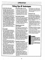
Suggestedtilling patterns
• When preparing a seedbed, go over the
same path twice in the first row, then
overlap one-half the tiller widthon the
rest of the passes (see Figure 3-15).
When finished in one direction, make a
second pass at a right angle as shown
in Figure3-16. Overlapeach pass for
best results (in very hard ground it
may take three or four passesto thoroughly pulverize the soil).
Failure to follow this warning could result in personal
injury.
. If the garden size will not permit
lengthwise and then crosswise tilling,
then overlap the first passes by onehalf a tiller width, followed by successive passesat one-quarter width (see
Figure 3-17).
19
,,
.
,
,
OPERATION
Tilling Tips & Techniques
Tilling on slopes
Tilling up and downslopes
If you must gardenon a moderate
slope, pleasefollow two very important
guidelines:
• To keepsoil erosion to a minimum, be
sureto add enoughorganicmatter to
the soil so that it has good moistureholding textureand try to avoid leaving
footprints or wheel marks.
1. Till only on moderate slopes, never
on steep groundwhere footing is difficult (review safety rules in the
"Safety" section of this manual).
2. We recommend tilling up and down
rather than across slopes or using
terraces cut into a slope. Tilling vet,,_ically qn a slope allows maximum
plantingarea and also leaves room
for cultivating.
iMPORTANT:When tilling on slopes,
besure the correctoil level is maintainedin the engine (checkevery onehalf hourof operation). The inclineof
the slopewill causethe oilto slantaway
from its normal leveland this can
starveengineparts of required lubrication: Keepthe engine oil levelat the full
_01nt'at all times!
• When tilling vertically,try to make the
first pass uphill since the tiller digs
more deeply going uphill than it does
downhill. In soft soil or weeds,you
may haveto lift handlebars slightly
whilegoing uphill. Whengoingdownhill, overlap the first pass by about
one-half the width of the tiller.
WARNING
Do not operate the tiller on
a slope too steep for safe
operation. Till slowly and
be sure that you have good
footing.
Failure to follow this warning could result in personal
injury.
Figure3-17
Figure3.15
A
1
!
!
Figure3-18
Figure 3-16
20
OPERATION
LOADING
ANDUNLOADING
THETILLER
WARNING
Loading and unloading the
tiller into a vehicle is potentially hazardous and we don't
recommend doing so unless
absolutely necessary, as this
could result in personal injury
or property damage.
However, if you must load or
unload the tiller, follow the
guidelines given next.
• Before loading or unloading, stop
the engine, wait for all parts to stop
moving, disconnect the spark plug
wire and let the engine and muffler
cool. Move the spark plug wire
away from the spark plug.
• The tiller is too heavy (165 to 240
Ibs., depending on model) and
bulky to lift safely by one person.
Two or more people should share
the load.
• Use sturdy ramps and manually
(with engine shut off) roll the tiller
into and out of the vehicle. Two or
more people are needed to do this.
each wheel to control the speed of
the tiller. Never go down ramps
tiller-first, as the tiller could tip forward.
• Ramps must be strong enough to
support the combined weight of the
tiller and any handlers. The ramps
should provide good traction to prevent slipping; they should have side
rails to guide the tiller along the
ramps; and they should have a
locking device to secure them to
the vehicle.
• Use wooden blocks to place on the
downhill side of the wheels if you
need to stop the tiller from rolling
down the ramp. Also, use the
blocks to temporarily keep the tiller
in place on the ramps (if necessary), and to chock the wheels in
place after the tiller is in the vehicle.
• The handlers should wear sturdy
footwear that will help to prevent
slipping.
• Position the loading vehicle so that
the ramp angle is as flat as possible (the less inclined the ramp, the
better). Turn the vehicle's engine
off and apply its parking brake.
• When going up ramps, stand in the
normal operating position and push
the tiller ahead of you. Have a person at each side to turn the wheels.
• When going down ramps, walk
backward with the tiller following
you. Keep alert for any obstacles
behind you. Position a person at
21
• When the tiller is in the vehicle, prevent it from rolling by engaging the
wheels in the wheel drive position
(move Wheel Gear Lever to ENGAGE). Chock the wheels with
blocks and securely tie down the
tiller.
CUSTOMER
RESPONSIBILITIES
WARNING
Before inspecting, cleaning or servicing the machine, shut off engine,
wait for all moving parts to
come to a complete stop,
disconnect spark plug wire
and move wire away from
spark plug.
Failure to follow these instructions can result in serious personal injury or
property damage.
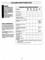
REQUIRED
MAINTENANCE
Before
Each
Use
PROCEDURE
SCHEDULE
Every
10
Hours
The warranty on this machine does
not cover items that have been subjected to operator abuse or negligence. To receive full value from the
warranty, the operator must maintain
the machine as instructed in this
manual.
Some adjustments will need to be
made periodically to properly maintain your machine.
Keep the air filters clean and change
the spark plug annually. A clean air
filter system and a new spark plug
will help your engine run better and
last longer.
Every
50
Hours
As
Noted
Lubricate Tiller
Checkfor 0il Leaks
CheckHardware
t
Checkgear oil level(see
"Transmission Gear0il Service")
t
Check engineoil level (see "Engine
Oil Service")
GENERAL
RECOMMENDATIONS
Every
30
Hours
And every
five
operating
hours
Changeengine oil (see "Engine
0il Service")
Service foam pre-cleaner air filter,
if so equipped (see"Air Cleaner
Service")
Every 25
hours*
Servicepaperairfilter (see"Air
CleanerService")
Every3O
hours*
Service Spark Plug
CleanEngine
•
Checktines for wear
(see "Tines")
°
Check/Adjust
Tension on
DriveBelts
•
t
* Changemore freque'ntlyin dusty or dirty conditions. Changeafter first 2 ho_'rs"of
break-in operation.
t
Checkafterfirst2 hours of break-in operation.
22
CUSTOMER
B
RESPONSIBILITIES
parts to come to a complete stop, disconnectspark plug wire and movewire away from spark
plug.
Failure Before
to follow
these cleaning
instructions
can result
in serious
injury
or
ARNING
inspecting,
or servicing
the unit,
shut offpersonal
engine, wait
for all
propertydamage.
,
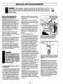
RegularMaintenance
Because the tiller is operated in the
garden, frequently under hot and
dirty conditions, regular maintenance
is very important to ensure that you
are getting proper performance from
your tiller. There are several maintenance procedures that will help keep
your tiller in good operating condition.
CheckFor Oil Leaks
F
Before each use, check your tiller for
signs of an oil leak - usually a dirty,
oily accumulation either on the unit
or on the floor where it has been
parked.
E
D
A little seepage around a cover or oil
seal is usually not a cause for alarm.
However, if the oil drips overnight
then immediate attention is needed
as ignoring a leak can result in severe transmission damage.
•o Change engine oil regularly.
• Lubricate the controls regularly.
• Keep the correct tension on the forward drive belt.
• Replace the engine air cleaner element when dirty.
If a cover is leaking, try tightening
any loose screws or bolts. If the fasteners are tight, a new gasket or oil
seal may be required. If the leak is
from around a shaft and oil seal, the
oil seal probably needs to be replaced. See your Sears Service
Center for advice.
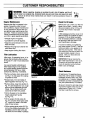
Figure4-1
• Keep engine cooling fins clean.
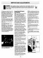
Tiller Lubrication
After every 10 operating hours, oil or
grease the lubrication points shown
in Figures 4-1 and 4-2 and described
below.
IMPORTANT: Never operate the
tiller if the transmission is low on oil.
Check the oil level after every 30
hours of operation and whenever
there is any oil leakage.
Use a good quality lubricating oil
(#30 weight engine oil is suitable)
and a good quality general purpose
grease (grease that has a metal
lubricant is preferred, if available).
• Remove wheels, clean wheel shaft
(A, Fig. 4-1) and apply thin coating
of grease to shaft.
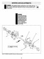
CheckHardware
At least every 10 operating hours,
check the unit for loose or missing
hardware (screws, bolts, nuts, hairpin cotters, etc.). Loose or missing
hardware can lead to equipment failure, poor performance, or oil leaks.
Figure4.2
• Grease back, front and sides of
depth regulator lever (B, Fig. 4-1).
• Remove tines, clean tine shafts (C,
Fig. 4-1) and inspect for rust, rough
spots or burrs (especially around
holes). File or sand smooth and
coat ends of shaft with grease.
Be sure to check the end cap mounting screws located at the rear of the
transmission (Figure 4-3). Lift the
tine flap to service the screws.
• Oil the threads on the handlebar
height adjustment handle
(D, Fig. 4-1).
• Oil the engine throttle cable (E,
Fig. 4-1) and the wheel gear cable
(F). Allow oil to soak in and then
wipe off any excess.
• Oil the various pivot points (G, Fig.
4-2) on the shifting mechanism, the
handlebar, and the idler arms (do
not allow oil on the belts or pulleys).
tl......
Figure4-3
23
CUSTOMER RESPONSIBILITIES
B
parts to come to a completestop, disconnectspark plug wire and movewire away from spark
plug.
Failure Before
to follow
these cleaning
instructions
can result unit,
in serious
injury
or
ARNING
inspecting,
or servicingthe
shut offpersonal
engine, wait
for all
propertydamage,
Transmission Gear 0il Service
Check the transmission gear oil level
every 30 hours of operation or when
you notice any oil leak. Operating
the tiller when the transmission is
low on.0il .can cause severe damage.
gear oil reaches the rear (tine) end
of the transmission. Stop adding
gear oil when it begins to flow from
the oil level check hole on the side of
the transmission.
8. Securely reinstall the check plug.
To CheckTransmissionGearOil Level
9. Securely reinstall the gear oil fill
plug on top of the transmission.
1. Check the gear oil level when the
transmission is cool. Gear oil will expand in warm operating temperatures and this expansion will provide
an incorrect oil level reading.
10. Reinstall the wheel and remove
the prop.
2. To check the gear oil level (and to
add oil, if needed), see "STEP 4:
Check Gear Oil Level in Transmission" in the Assembly Section of this
manual.
To Drain and Refill the Transmission
The transmission gear oil does not
need to be changed unless contaminate d with dirt, sand or metal bits.
1. Prop up the left side of the unit so
that it will be securely supported
when the left side wheel is removed.
Remove the left side wheel by removing the wheel pin.
2. Unscrew the gear oil fill plug from
the top of the transmission.
3. Place a clean pan below the
transmission drain plug (see Figure
4-4) and remove the drain plug. The
oil will start flowing out of the drain
hole (it may flow slowly, especially in
cold temperatures).
4. Remove the transmission gear oil
level check plug located a few inches above the left side wheel shaft.
5. When the oil stops flowing, tilt the
transmission forward to drain oil from
the rear of the transmission.
6. After draining the oil, clean the
threads of the drain plug, apply a
non-hardening, removable gasket
sealant to the threads, and securely
reinstall the drain plug.
7. U_ihg a clean funnel, slowly add
SAE 140 or SAE 85W-140 weight
gear oil (with an API rating of GL-4
only) to the transmission. The transmission holds approximately 3-1/4
pints (52-54 ounces). Tilt the tiller
slightly backwards to make sure the
t
,,.-._
,
To Changethe Engine0il
Only use high quality detergent oil
with an A.P.I. rating of service ciassification "SF", "SG", "SH" or "SH/CD."
Select the oil SAE viscosity grade
according to your expected operating temperature:
colder-.<.----.--
32OF..--_
5W30
• warmer
SAE 30
NOTE: Although multi-viscosity oils
(5W30, 10W30, etc. improve starting
in cold weather, these multi-viscosity
oils will result in increased consumption when used above 32°1::. Check
your engine oil level more frequently
to avoid possible engine damage
from running low on oil. DO NOT
USE 10W40 OIL.
1. Start engine and let it warm up.
Then TURN THE ENGINE OFF.
Figure4-4: Removedrainplugtodrain
transmission
gearoff(alsoremoveofffill
plugandoil levelcheckplug).
EngineOil Service
Check the engine oil level before
starting the engine each day and
check it after 5 hours of continuous
operation. Running the engine when
low on oil will quickly ruin the engine.
It is recommended that you change
motor oil after every 10 hours of operation (sooner when operating in
extremely dirty or dusty conditions.)
To Checkthe Engine0il Level
1. Move the tiller to a level area and
shut off the engine.
2. Level the engine by putting the
Depth Regulator Lever in the second
notch from the top.
2. There is an oil drain plug on each
side of the engine base. Use
whichever one is most convenient.
3. Place a 2"x4" wood board under
the wheel opposite the drain plug
you'll be removing.
4. Place a drain pan beneath the
drain plug.
5. Remove the drain plug (Figure
4-5), and allow the old oil to drain
completely.
e. Reinstall drain plug securely.
7. Remove wood board from beneath the wheel.
8. Remove the dipstick from the oil
fill tube (see Figure 4-5). Using a
funnel in the tube, refill the engine
with the correct type and weight engine oil. Check the level frequently
while filling so as not to overfill. Fill
until oil is at the FULL mark on the
dipstick. Install the dipstick.
3. Clean the area around the oil dipstick or oil fill tube to prevent dirt
from falling into the crankcase.
4. Remove the oil dipstick from the
oil fill tube, wipe the diihstick clean,
and reinstall it finger-tight. Remove
the dipstick and check the reading.
Add oil (if required) to bring the level
to the FULL mark. Do not overfill.
Figure4-5
24
CUSTOMER
g
parts to come to a completestop, disconnectspark plug wire and movewire away from spark
plug.
Failure Before
to follow
these cleaning
instructions
can result
in serious
injury
or
ARNING
inspecting,
or servicing
the unit,
shut offpersonal
engine, wait
for all
propertydamage.
A'irCleanerService
ToService Filters:
Inner
Paper
Filter
Outer
Foam
Filter
t
,,-..
e. Slide foam filter over paper filter.
The engine air cleaner filters dirt and
dust out of the air before it enters the
carburetor. Operating the engine
with a dirty, clogged air filter can
cause poor performance and damage to the engine. Never operate
the engine without the air cleaner installed. Inspect and service the air
cleaner more often if operating in
• very dusty or dirty conditions.
The air cleaner assembly is
equipped with a foam filter and an
inner paper filter. Service the filters
according to the "Required Maintenance Schedule" on Page 22.
Base
Plate
RESPONSIBILITIES
Cover
and Wing
Nut
Figure4-6: Aircleanercomponents.
7. Install cover and wing nut. Tighten wing nut securely.
SparkPlug Service
Inspect and clean or replace the
spark plug after every 100 operating
hours or annually.
In some areas, local law requires using resistor spark plugs to suppress
ignition signals• If the engine was
originally equipped with a resistor
spark plug, use the same type for replacement.
To Service the Spark Plug
1. Clean area around spark plug.
2. Remove and inspect plug.
3. Replace plug if electrodes are pitted, burned, or porcelain is
cracked. For replacement, use a
Champion RJ-17LM only. NOTE:
A resistor plug must be used for
replacement.
4. Check electrode gap with wire
feeler gauge and set gap at .030 if
necessary.
5. Install spark plug and tighten
securely.
Outer Foam Filter-• Wash in water and detergent solution and squeeze until all dirt is removed.
• Rinse thoroughly in clear water.
• Wrap in a clean cloth and squeeze
until 'completely dry.
• Do not oil the foam filter.
Inner Paper Filter--DO NOT
ATTEMPT TO CLEAN OR OIL THIS
FILTER.
• Replace annually or every 30 operating hours (more often under very
dusty conditions).
To Remove and Install Filters:
1. Remove wing nut and cover.
2. Slide foam filter off paper filter.
3. Discard paper filter.
4. Clean inside of base and cover
thoroughly.
CoolingFins
SparkArresterScreenService
If the engine muffler is equipped with
a spark arrester screen, remove and
clean away any accumulated material on the screen. Check to see that
the screen is not burned through in
any places or damaged. Replace a
spark arrester screen if it is burned
through or damaged in any location.
EngineCleaning
The engine must be kept clean to
assure smooth operation and to prevent damage from overheating. The
engine cooling fins (see Figure 4-6A)
should not be allowed to accumulate
any materials such as leaves, twigs,
or other debris. All inspections and
services must be done with the engine shut off and cool to the touch•
5. Install new paper filter on base.
25
Figure4.6A:Keepcoolingfinsclean.
Carburetor/Governor
Control
Adjustments
The carburetor was adjusted at the
factory for best operating speed, if
an adjustment is needed, contact
your nearest Sears Service Center.
The governor controls the maximum
safe operating speed and protects
the engine and all moving parts from
damage caused by overspeeding.
Do not tamper with the engine governor settings. Contact your nearest
Sears Service Center if a problem
exists.
WARNING
Operators shall not tamper
with the engine governor
settings on the machine;
the governor controls the
maximum safe operating
speed to protect the engine and all moving parts
from damage caused by
overspeed. Authorized service shall be sought if a
problem exists.
Throttle ControlAdjustment
If the engine does not respond properly to various throttle lever settings,
please contact your nearest Sears
Service Center for assistance.
SERVICE AND ADJUSTMENTS
E
parts to cometo a completestop, disconnectspark plug wire and move wire away from spark
plug.
Failure Before
to fallow
these instructions
can result
in serious
injury
or
ARNING
inspecting,cleaning
or servicing
the unit,
shut off personal
engine, wait
for all
propertydamage.
WheelGearGableAdjustment
Tines
When the Wheel Gear Lever is in
DISENGAGE, the wheels will roll
freely (freewheel). The wheels
should not roll freely when the lever
is in ENGAGE. If the wheels roll
freely when the Wheel Gear Lever is
in ENGAGE, the wheel gear cable
needs to be adjusted as described
below.
The tines will wear with use and
should be inspected at the beginning
of each tilling season and after every
30 operating hours. Tines can be replaced individually or as a complete
set. Never inspect or service the
tines unless the engine is stopped
and the spark plug wire is disconnected.
1, With the engine shut off and the
spark.plug wire disconnected, put
the Wheel Gear Lever in ENGAGE.
NOTE: You must first remove the
tiller hood in order to take off either a
single tine holder or individual tines.
The hood is secured to the transmission housing with two rear bolts and
two front bolts. Remove all four
bolts and set the hood aside to have
full access to the tines.
2. Loosen the top adjustment nut (A,
Figure 4-7) on the wheel gear cable
bracket that is located on the left
side rear of the transmission.
3. Push the wheel gear cable (B)
down and roll the tiller slightly forward or backward until the eccentric
lever (C) engages (locks) the
wheels. Hold the cable in that position and tighten the top (A) and bottom (D) adjustment nuts.
4. Move the Wheel Gear Lever to
ENGAGE and DISENGAGE several
times to check the adjustment. The
wheels should not roll when the lever
is in ENGAGE, but they should roll
when the lever is in DISENGAGE.
Readjust the cable as required.
t
..--.
Removing
andInstalling
Tine Inspection
With use, the tines (Figure 4-8) will
become shorter, narrower and pointed. Badly worn tines will result in a
loss of tilling depth and reduced effectiveness when chopping up and
turning under organic matter.
Tine Assemblies
1. Use a 9/16" socket, 6" extension,
a ratchet, and a 9/16" box wrench to
loosen the nut (A, Figure 4-9) and
bolt (B) that secure the tine holder to
the tine shaft.
2. Use a rubber mallet to tap the tine
holder loose.
3. Slide the tine assembly off the tine
shaft.
4. RePeat Steps 1-through-3 abo..ve
to remove the other tine assembly.
5. Installing the tine assembly is simply the reverse of its removal. Be
sure the cutting edges face so they
will enter the soil first when the tiller
is moving forward- this means the
cutting edges face toward the operator position.
First be sure to remove any rust, uneven spots or burrs from the tine
shaft, using fine sandpaper. Then
grease the tine shaft before reinstalling the tine assemblies. Tighten
the hardware very securely.
Removingand Installing
IndividualTines
1. Use two 9/16" box end wrenches
to remove the two bolts (C, Figure
4-9), and nuts (D) that secure the
tine to its tine holder. See Figure 4-9.
NOTE: If the nuts are rusted, apply
penetrating oil to the bolt and nut.
Let the oil soak in for a few minutes
before loosening the nut. Always
loosen the nut rather than the bolt.
Figure4-8: Checktinesforwearafterevery
30 operatinghours.
Figure4.7: Wheelgearcableassembly,
26
2. When installing individual tines, install them in the reverse order from
which they were removed. The two
sets of inboard tines are installed so
one set faces toward the transmission housing and the other faces
away from it. The single outboard,.
tine set faces toward the transmission housing. Also be sure the cutting edges face so they will enter the
soil first when the tiller is moving forward- this means the cutting edges
face toward the operator position.
SERVICE AND ADJUSTMENTS
i
parts to come to a complete stop, disconnectspark plug wire and movewire away from spark
plug.
Failure Before
to follow
these instructions
can result unit,
in serious
injury
or
ARNING
inspecting,
cleaning or servicingthe
shut offpersonal
engine, wait
for all
propertydamage.
t_
WARNING
This is a CRT(counter-rotating tine) tiller and its tines
must be mounted in the direction shownin Figure4-9.
It mounted with curves in
the oppositedirection, tiller
will dlg poorlyend be more
likely to runbackwards.
Failure to comply could result in personal injury or
propertydamage.
A
Figure4-9: Completetineassemblies:
fineholders,all tinesandhardware.
27
....
;,
SERVICE AND ADJUSTMENTS
g
.....
partsto cometo a complete stop, disconnectspark plug wire and movewire away from spark
plug.
Failure Before
to follow
these instructions
can result unit,
in serious
injury
or
ARNING
inspecting,
cleaning or servicingthe
shut offpersonal
engine, wait
for all
propertydamage.
CheckingAndAdjustingThe
TensionOnThe DriveBelts
Maintaining correct tension on the
drive betts is important to good tilling
performance and long belt life. A
loose belt will slip on the engine and
transmission pulleys and cause the
tines and wheels to slow down - or
stop completely - even though the
engine is running at full speed. A
loose belt wilt also result in premature wear to the belt.
While checking belt tension, atso
check for cracks, cuts or frayed
edges. A belt that is in poor condition
should be replaced.
The tension on a new forward drive
belt should be checked after the first
two (2) hours of operation. Thereafter, check the tension after every
ten (10) hours of operation.
The reverse drive belt, because it is
used more sparingly, will probably
not require an initial tension adjustment until a significant number of operating hours has passed.
WARNING
Follow the belt adjustment instructions carefully. An incorrect adjustment could result in
the Forward Clutch mechanism
engaging too soon. This could
cause loss of tiller control and
result in personal injury or
property damage.
To Checkand AdjustTensionon the Forward DriveBelt:
1. The check for correct belt tension
is the same as that described in Step
5 of "Step 3: Attach Forward Clutch
Rod" on page 9. Before performing
this check, shut off the engine, disconnect the spark plug wire, and allow the engine and muffler to cool
down. If, after following the adjustment procedures, you cannot get the
correct gap on the forward clutch rod
adjustment bracket, you will need to
make a secondary adjustment as described next.
2. Disconnect the Forward Clutch
Rod (A, Figure 4-10) from the swivel
plate (B) by removing the innermost
hairpin cotter (C).
3. Unthread the Forward Clutch Rod
(in a counterclockwise direction as
viewed from the front of the unit) until one or two threads on the rod extend above the rectangular nut (D,
Figure 4-11) on the forward clutch
bracket.
t
,,,.-..
Removebelt (E)]
from grooveand t
off pt
4. Remove the belt cover.
5. From the right side of the unit, slip
the forward drive belt (E, Figure 410) out of the pulley groove closest
to the engine (this forward drive pulley has two grooves) by pushing it
off (away from the engine) with your
left hand while pulling the engine
starter rope with your right hand.
(The forward drive belt should have
been located in the pulley groove
closest to the engine; not in the
groove furthest from the engine.)
6. On the left side of the unit (as
viewed from operator's position) remove the hairpin cotter from the clevis pin (F, Figure 4-12) that connects
the forward idler arm (G) to the forward adjustable link (H). Push inward on the forward idler arm (G)
and remove the clevis pin (F).
7. There are two holes in the forward
adjustable link (H, Figure 4-12).
Push inward on the forward idler arm
(G) and install the clevis pin (F)
through the inner hole in the forward
adjustable link (H) and out through
the single hole in the forward idler
arm (G). Secure the clevis pin with
the hairpin cotter.
NOTE: While pushing inward on the
forward idler arm, be sure that the
forward drive belt is moved off to the
right side of the tiller. This creates
more room to install the clevis pin
when the forward idler arm is pushed
inward.
28
Figure4-10: Disconnect
ForwardClutch
Rodandmoveforwarddrivebeltoutof
groovein engineforwarddrivepulley.
Figure4.11 Oneor_vothreadsonForward
ClutchRodshouldbe exposed
aboverectangularnut.
IMPORTANT: With the clevis pin installed in the inner hole of the forward adjustable link, the number of
additional belt tension adjustments
that can be made is limited. If, with
future tension adjustments, you find
that you cannot screw the forward
clutch rod any farther into the rectangular nut on the forward clutch
bracket, it means that the forward
drive belt must be replaced. Before
doing so, the clevis pin must be returned to the OUTSIDE hole in the
forward adjustable link.
SERVICE AND ADJUSTMENTS
partsto come to a complete stop, disconnectspark plug wire and move wire away from spark
plug. Failure Before
to follow
these cleaning
instructions
can result
in serious
injury
or
WARNING
inspecting,
or servicing
the unit,
shut offpersonal
engine, wait
for all
propertydamage.
8. Replace the forward drive belt in
the High speed groove of the engine
drive pulley (the groove closest to
the engine) and in the middle groove
i_ the tr_.nsmission pulley. Be sure
the belt is to the inside of the wire
formed belt guide (I, Figure 4-13) and
to the inside of the forward drive idler
pulley (J).
9. Reinstall the belt cover and secure it with the two nuts.
10. Readjust the forward drive belt
tension by following the instructions
'in,'item' 5 of "Step 3: Attach Forward
Clutch Rod" on Page 9.
t
=--.,
• The belt tension is correct if the
guide mark (M, Figure 4-15) is anywhere to the left of the guide pin
(O), as viewed from the front of the
unit (not the operator's position). If
the belt tension is correct, reinstall
the belt cover and secure it with the
two nuts.
• If the guide mark is aligned with the
guide pin, or moves to the right
side of the guide pin, then the belt
is too loose and the tension must
be readjusted as described next.
3. The reverse idler pulley (L, Figure
4-14) regulates the tension that is
applied to the reverse drive belt (P).
The following adjustment will allow
the reverse idler pulley to apply more
tension to a loose belt.
Figure4-14 : Reverseidler arm(K)andre.
versepulley(L).
4. Remove the belt cover.
5. Slip the reverse belt (P, Figure 414) off the engine driven reverse
(upper) pulley.
Figure4.12: Removeclevispin fromouter
holein forwardadjustablelinkandmoveto
innerholein link.
6. On the right side of the unit (as
viewed from operator's position) remove the hairpin cotter from the clevis pin (R, Figure 4-14) that connects
the reverse idler arm (K) to the reverse adjustable link. Push inward
on the reverse idler arm (K) and remove the clevis pin (R).
To Checkand AdjustTensionan the Reverse Drive Belt
Figure4-15: Whilepushingreverseidlerarm
Inward,standat engineend andcheckposi.
t/onofguidemark(#7)andguidepin(0).
1. Remove the belt cover after first
shutting off the engine, disconnecting the spark plug wire, and allowing
the engine and muffler to cool down.
2. Stand at the front of the tiller and
use your left hand to push the reverse idler arm (K, Figure 4-14) inward as far as possible (the reverse
idler pulley [L] is attached to the reverse idler arm). Hold the idler arm
in this position and look at the position of the belt tension guide mark
(M, Figure 4-15) that is stamped into
the face of the reverse adjustable
link (N, Figure 4-15).
Figure4-13: Topviewofbeltsandpulleys.
29
SERVICE AND ADJUSTMENTS
parts to come to a completestop, disconnectspark plug wire and movewire away from spark
g
plug. Failure Before
to follow
these cleaning
instructions
can result
in serious
injury
or
WARNING
inspecting,
or servicing
the unit,
shut offpersonal
engine, wait
for all
it--.
propertydamage.
7. There are two holes in the reverse
adjustable link (S, Figure 4-16).
Push inward on the reverse idler arm
(K) and install the clevis pin (R)
through the inner hole in the reverse
adjustable link (S) and out through
the single hole in the reverse idler
arm (K). Secure the clevis pin with
the hairpin cotter.
8. Reinstall the reverse belt (P, Figure
4-14) on the reverse (upper) pulley,
making sure the belt is located to the
inside of the reverse idler pulley (L,
Figure 4-14).
9. Reinstall the belt cover and secure it with the two nuts.
IMPORTANT: If, in future tests for
reverse belt tension, the guide mark
should again align with or move to
the right side of the guide pin, it
means that the reverse belt is worn
beyond adjustment. Before installing
a new belt, you must return the clevis pin to the OUTSIDE hole in the
reverse adjustable link.
ForwardDriveBelt Removal
AndInstallation
NOTE: This model has one forward
speed (High) and one reverse
speed. The High Speed groove in
the forward engine pulley (the
groove closest to the engine) is the
only groove that should be used in
this pulley. Do not use the groove in
the forward engine pulley that is furthest from the engine. The reverse
pulley has just one groove. The transmission pulley has three grooves-do not use the groove closest to the
transmission housing.
Removingthe ForwardDrive Belt:
1. Stop the engine, allow it to cool
and disconnect the spark plug wire
before working near the belts.
2. Remove the reverse drive belt
completely (A, Figure 4-17) by following the "Removing the Reverse Drive
Belt" instructions in this section.
3. Move the forward drive belt (B,
Figure 4-17) completely off the engine forward drive pulley (D).
4. Slip the forward drive belt completely off the transmission drive pulley (C, Figure 4-17) by moving it to
the front of the pulley.
NOTE: For additional working room,
loosen the reverse belt guide (V, Figure 4-13) and twist it out of the way.
4. Put the lower half of the belt into
the middle groove of the transmission pulley (C, Figure 4-17).
5. Put the upper half of the belt on
the engine forward drive pulley in
the groove closest to the engine (B,
Figure 4-17).
IMPORTANT: Make sure that the ,.
forward drive belt is to the inside of
the wire belt guide (I, Figure 4-13)
and the forward idler pulley (J, Figure 4-13).
6. If you loosened the belt guide,
wait until the reverse drive belt is installed before securing the belt
guide.
7. Install the reverse drive belt.
8. Install the belt cover and secure it
with the two nuts.
9. If you installed a new belt, check
the tension after two hours of operation.
D
BA
5. Pull the forward drive belt up and
away by feeding the bottom half of
the belt in between the engine and
transmission pulleys.
Installingthe ForwardDrive Belt:
1. The reverse drive belt must be removed before installing the forward
drive belt.
Figure4-16: InstallingclevispinIn Inside
holeofreverseadjustable
link.
2. Slip the forward drive belt down
between the rear of the engine forward drive pulley (D, Figure 4-17)
and feed the bottom half in between
the engine and transmission pulleys
(see Figure 4-18). Be sure that the
belt is to the inside of the forward
idler pulley and forward belt guide
(see J and I, Figure 4-13).
3. Slip the forward drive belt down
and over the front of the transmission pulley (C, Figure 4-17).
3O
C
Figure4-17: Beltdrivesystem.
SERVICE AND ADJUSTMENTS
g
parts to come to a completestop, disconnectspark plug wire and move wire away from spark
plug.
Failure Before
to follow
these cleaning
instructions
can result
in serious
injury
or
ARNING
inspecting,
or servicing
the unit,
shut offpersonal
engine, wait
for all
propertydamage.
t
,,.....
Installingthe Reverse Drive Belt
1. Slip the reverse belt down between the engine reverse pulley (A,
Figure 4-19) and the engine forward
drive pulley (C).
Figure4.18: Installforwarddrivebeltover
rearofengineforwardpulleyandbringlower halfofbelldownandin frontoftransmissionpulley.
Reverse Drive Belt Removal
and Installation
NOTE: The forward drivebelt must
be installedbeforeinstallingthe reversedrivebelt.
2. Loop the bottom half of the belt
over the front of the transmission
pulley (B, Figure 4-19) and seat the
belt in the front groove of the pulley.
3. Place the belt to the inside of the
reverse idler pulley (D, Figure 4-19)
and the reverse belt guide (V, Figure
4-13). Then slip the upper end into
the groove of the engine reverse pulley (A, Figure 4-19).
4. If the reverse belt
4-13) was loosened
ter the belt guide on
tighten the mounting
guide (V, Figure
previously, centhe belt and
screw securely.
5. Install the belt cover and secure it
with the two nuts. If the lower transmission cover was removed, reinstall
it with the four self-tapping screws,
'Removingthe Re_'erseDrive Belt
1. Stop the engine and allow it to
cool before working near the belts.
Be sure the spark plug wire is disconnected.
2. Remove the belt cover by removing the two nuts. For easier access
to the transmission (lower) pulley, remove the transmission cover located
below the transmission pulley.
3. Slip the reverse belt off the engine
reverse pulley (A, Figure 4-19). If
necessary, work the belt off the pulley with your left hand while pulling
the engine recoil starter rope with
your right hand.
4. Push the upper half of the reverse
belt downward to create slack in the
belt. Then reach underneath the
transmission and slip the belt off the
front of the transmission pulley (B,
Figure 4-19).
'5. Pull the belt up and past the engine reverse pulley (A, Figure 4-19).
31
B
Figure4-19: Removing
andinstallingre.
versabelt.
STORAGE
TiBerStorage
DANGER
Whenever you don't intend to use
your tiller for 30 days or longer, you
should perform the following steps to
ensure that it will start easily and
perform properly when removed
from storage.
Gasolineis highlyflammableanditsvaporsare explosive.Followthesesafety
practicesto preventinjuryor propertydamagefrom fire or explosion.
• Thoroughly clean the machine.
• Wipe up spills and pushthe tiller away from spilled fuel.
• Be sure that all nuts, bolts and
screws are securely fastened. Inspect parts for damage, breakage
or wear. Replace as necessary.
• Use onlyan approvedfuel containerand store it safely from children.
• Touch up all rusted or chipped
• paint surfaces. Sand lightly before
repainting.
• If possible, store your unit indoors
and cover it with a suitable protective oover (not plastic) that does
not retain moisture.
IMPORTANT: Never cover the unit
while the engine and exhaust areas
are still warm.
• Do not store gasoline from one
season to another.
• Replace your gasoline can if it
starts to rust. Rust and/or dirt in
your gasoline will cause problems.
EngineStorage
Fuel System
IMPORTANT: It is important to prevent gum deposits from forming in
essential fuel system parts such as
carburetor, fuel filter, fuel hose, or
tank during storage. Also, experience indicates that alcohol blended
fuels (called gasohol or using
ethanol or methanol) can attract
moisture which leads to separation
and formation of acids during storage. Acidic gas can damage the fuel
system of an engine while in
storage.
• Let engineand mufflercoolat least 2 minutesbeforedrainingfuel tank.
• Do not allow openflames, sparks,or matches,or permit smoking in fuelingarea.
• Do not store gasoline in an area where its vapors could reach an open
flame or spark, or where ignition sourcesare near (such as hot water and
space heaters, furnaces, clothesdryers, stoves, motors, etc.)
• Drain the fuel tank.
EngineCylinder
• Start the engine and let it run until
the fuel lines and carburetor are
empty.
• Remove spark plug. Squirt one (1)
oz. (30ml) of clean engine oil into
spark plug hole.
• Never use engine or carburetor
cleaner products in the fuel tank or
permanent damage may occur.
• Use fresh fuel next season.
• Cover spark plug hole with a clean
rag.
NOTE: If "Gasohol" has been used,
run engine until the tank is empty.
Then put 1/2 pint of "Unleaded" regular gasoline into the fuel tank and
again run the engine until tank is
empty.
• Install spark plug. Do not connect
spark plug wire.
NOTE: Fuel stabilizer (such as
Craftsman Fuel Stabilizer No.
33550) is an acceptable alternative
in minimizing the formation of fuel
gum deposits during storage. Add
stabilizer to gasoline in fuel tank or
storage container. Always fo]low the
mix ratio and instructions on the stabilizer container. Run engine at least
10 minutes after adding stabilizer to
allow the stabilizer to reach the carburetor. Do not drain the gas tank
and carburetor if using fuel stabilizer
EngineOil
Drain oil and replace with clean engine oil. See "Engine Lubrication" in
the CUSTOMER RESPONSIBILITIES section.
32
• Pull starter rope to crank engine
over, slowly, several times.
TROUBLESHOOTING
TROUBLESHOOTING
Beforeperforming any corrections, refer to the appropriate information in this Manualfor the correct safety precautions and operating or maintenanceprocedures. Contact your local Sears Service Center for necessary service.
PROBLEM
Enginedoes
notstart,
CORRECTION
POSSIBLECAUSE
1. Sparkplugwire disconnected.
2. EngineThrottLeControlLeverincorrectlyset.
3. Fueltankempty.
4. Chokecontrol(if so equipped)in incorrect position.
5. Stalegasoline.
6. Dirty airfilter(s).
7. Detectiveor incorrectlygappedspark plug.
8. Carburetorout of adjustment.
9. Misadjustedthrottle controlcable.
10. Dirt or water infuel tank.
1. Reconnectwire.
2. Putleverin STARTposition.
3. Addfuel.
4, Moveleverto correctposition.
i. Drain fuel andaddfresh fuel.
6. Cleanor replacefilter(s).
7. Inspect sparkplug.
8. ContactSearsServiceCenter.
9. ContactSearsServiceCenter.
10, ContactSearsServiceCenter.
Enginerunspoorly.
1. Defectiveor incorrectlygappedsparkplug.
2. Dirty air filter(s).
3, Carburetorout of adjustment.
4. Stalegasoline.
5. Dirt or water in fuel tank,
6. Enginecoolingsystem clogged.
1. Inspectspark plug (see"CustomerResponsibilities").
2. Cleanor replace(see"CustomerResponsibilities").
3. ContactSearsServiceCenter.
4. Replacewith fresh gasoline.
5, ContactSearsServiceCenter.
6. Cleansir coolingsystem(see"CustomerResponsibilities"),
Engineoverheats,
1. Enginecoolingsystemclogged.
2, CarburetorOutof adjustment.
3. Oil levelis low.
1. Cleanair coolingarea (see"CustomerResponsibilities").
2. ContactSearsServiceCenter.
3. Checkoil level(see"CustomerResponsibilities"),
1. Misadjustedthrottle controlcable.
1. ContactSearsServiceCenter.
1. Improper useof controls.
2. ForwardDrive: Misadjustadforward clutchrod.
3. ReverseDrive:Brokenor misadjustedbelt.
1. Review"Operation"section.
2. See"HandlebarHeightAdjustment"
in "Operation"section.
3. Replacebelt or adjust belttension (see"Serviceand
Adjustments"
section.
4. See=CheckingDriveBeltTension(see"Serviceand
Adjustments"section.
5. ContactSearsServiceCenter.
6. Tightenholt; checkthatkeyisin place.
Engine
doesnot
shutoff.
WheelsandTines
will notturn.
4. Worn,broken,or misadjusted
drivebelt(s).
5. Internaltransmission
wearor damage.
6. Boltandkeylooseintransmission
pulley.
4. Wheel GearLevernot fully engaged.
1. Replacehardware.
2. ContactSearsServiceCenter.
3. See"WheelGearCableAdjustment" in "Serviceand
Adjustments"section.
4. Engagelever(see"Operation"section.
WheelsTurn,but
TinesDon't.
t. Tine holdermounting hardwaremissing,
2. Internaltransmission wearor damage.
1, Replacehardware.
2. ContactSearsServiceCenter.
Poortilling
partormance.
1. Worn tines,
2. improper DepthRegulatorse_ing.
3. Lncorrectthrottle
se_ino.
4. Belt(s)slipping.
1. See"Tines"in "Service andAdjustments"
section.
2. See"Tilling Tips & Techniques"
in "Operation"Section,
3, See"Operation"Section.
4. See"Checking DriveBeltTension"in"Serviceand
Adjustments"
section.
Tinesturn,but
wheelsdon't.
1. Wheelmounting hardwaremissing.
2. Internaltransmission wear or damage.
3. Misadjustedwheel gearcable.
33
OPERATING AND SAFETY DECALS
E,
A,
B,
Ce
F.
Keepawayfrom
rotating
tines.
Rotating
causetineswill
injury.
D,
pad# _
Descriptionand Location
Qty.
Owner'sManualReplacement.........................................
1
B
1909942
1911361
WARNING- KeepAwayFromTines .....................................
1
C
1915810
D
1904547
StartingStabilizationInstructions......................................
HoodDecal .......................................................
1
1
1916612
ControlPanel ......................................................
1
1904549
WARNING-HotSurface ..............................................
1
Ref. Le_er
A
E,*
F
,,
34
CRAFTSMAN
8HP MODEL 987.293330 REPAIR PARTS
FORWARD/REVERSE
IDLERASSEMBLY
8
9
CLUTCH ROD *
REVERSE
CLUTCH ROD*
11
13
lO
" 19
6
\
TOP COVER
12
\
4
* see "Handlebar Assembly and
Conb'ol Levers" drawing
7
REF
No.
'1
2
3
4
5
6
7
8
9
10
11
12
13
14
15 '
PART
NO.
DESCRIPTION
1185506
1110043
1909266
9193
1113-1
9338
1110108
1186230
1100242
20545
9479
1916192001
Locknut-hex,3/8-16 .....................
Screw-hex hd, 3/8-16 x 1-1/4"*...
Pulley-idler, reverse tiller direction
Pulley-idler, forward tiller direction
Spacer...........................................
HaLrpinCotter................................
Locknut-hex, 3/8-16 .....................
Nut-hex, 5/16-18 ..........................
Lockwasher-5/16 ..........................
Washer-plain, 5/16 .......................
Pivot Bushing................................
Idler Arm-left, forward tiller
direction....................................
1909682001 Idler Arm-right, reverse tiller
direction ....................................
1492
Spring ...........................................
Forward Link .................................
20517-01
REF
No.
QTY.
16
17
18
19
20
21
22
23
24
25
26
27
28
1
1
1
1
1
2
2
2
2
2
2
1
1
1
1
** Specify GRADE5 if ordering part locally.
35
PART
No.
20517-02
9340
1916194001
1111607
1916195001
20553
9532
20546
1916196001
1100043
1916897
20532
1186331
DESCRIPTION
ReverseLink .................................
Pin ................................................
Mounting Bar ................................
Screw-hex hd., 5/16-18 x 2-1/4"*
Shifting Base.................................
Spacer-Bushing ............................
Klip Ring .......................................
Washer-pivot ................................
Beilcrank .......................................
Screw-hex hd., 3/8-16 x 1-1/4"*..
Pivot-for ReverseClutch lever ......
Bushing-bellcrank ........................
Screw-flanged hex hd.,
5/16-18 x 1". .............................
QTY.
1
2
2
2
1
2
1
1
1
1
1
1
4
CRAFTSMAN
8HP MODEL 987.293330
REPAIR PARTS
HANDLEBAR
ASSEMBLY& CONTROLLEVERS
2j
21
4
21
34
I
3
ADJUSTER ASSEMBLY
PART 26
12
35
16
4O
BELLCRANK
43
OP COVER
36
CONNECT TO BELLCRANK
CRAFTSMAN
8HP MODEL 987.293330
REPAIR PARTS
HANDLEBARASSEMBLY& CONTROLLEVERS
REF
No.
PART
No.
DESCRIPTION
QTY.
1916766
Handlebars-(incl,Ref. No,'s 2, 3,
3A and 4) ...................................
2
9126
Grip-handlebars ...........................
3
1918812
Decal- for operatorcontrolpanel.,
3A
1916810
Decal- Logo ..................................
' 4'
9251
Grommet-plastic (part of operator
controlpanel).............................
5
20703
Handle, height adjustment .............
5A
9955
Washer-keyed ...............................
6
1900475001 Bracket-handlebar height adjust...
7
1100046
Screw-hex hd., 3/8-16 x 1 *. ..........
8
9904
Washer-plain (flat) 3/8, S.A.E........
9
9837
Locknut-hex, 3/8-16 .....................
10
9338
Hair Pin Cotter ...............................
11
1916896
ReverseClutch Levercomplete (incl. grip, #9198) .......
12
9198
Grip-reverseclutch lever...............
13
1916639
Wheel GearControl & Cable
Assy...........................................
14
9057
Knob-wheel gear control lever ......
15
1186211
Nut-hex, 5/16-24, wheel gear
cable adjustment ........................
16
1100068
Screw-hex hd., 3/8-16 x 3/4". ......
17
1100243
Lockwaaher-3/8 ............................
18
9445
EngineThrottle Control & Cable....
19.... 9202
Ties-plastic ....................................
20
9212
Knob-throttle control lever............
21
1114748
Screw-round hd, No. 10-32 x 1/2.
22
1100240
Lockwasher-No. 10 .......................
1
2
1
1
1
1
1
1
2
2
2
3
1
1
1
1
2
2
2
2
4
1
8
4
REF
No.
PART
No.
23
24
25
1186208
9390
20863
26
20862
27
28
29
30
31
32
33
34
35
36
37
38
39
40
41
42
9532
20808
20809
9059
9522
9386
20831
97083
9853
20806
20888
9432
9973
1100805
9811
9552
43
20545
* SpecifyGRADE5 if orderingpart locally.
37
DESCRIPTION
QT_
Nut-hex, No. 10-32 ....................... 4
Grip-paddle ................................... 2
Bail-forwardclutch control(incl.
two Grips, Ref. No. 24) .............. 1
Adjuster Assembly (incl. Ref. No.'s
27, 28, 29, 30, 38 and 39) .......... 1
Kllp Ring........................................ 2
Adjuster, Right Side....................... 1
Adjuster, Left Side ......................... 1
Spring-Adjuster ............................. 1
Nut-rectangular ............................. 1
Klip Ring........................................ 1
Rod-forward clutch ....................... 1
Pin-Clevis...................................... 1
Seres Nut....................................... 4
Bracket-bailsupport...................... 2
Swivel............................................ 1
Bushing ......................................... 1'
Washer .......................................... 1
Screw-hex hd., 1/4-20 x 3/4". ...... 1
Nut-I/4-20 .................................... 1
Screw-flanged hex hd, selftapping, 1/4-20 x 1/2". ............... 2
Washer- flat, 5/16". ....................... 1
CRAFTSMAN
8HP MODEL 987.293330 REPAIR PARTS
HOOD,BRACKET& DEPTHREGULATOR
22
21
17
17B
12
10
20
19
11
23
22
2O 23
17A
9
6
7
TRANSMISSION
13
/
4
<
13
38
CRAFTSMAN
8HP MODEL 987.293330 REPAIR PARTS
HOOD, BRACKET & DEPTH REGULATOR
,I
i
REF
No,
PART
NO.
1
1916764
2
3
4
5
6
7
8
9
10
11
12
13
DESCRIPTION
Hood-tine cover,with hinged flap
(Incl. Ref. No. 17, 17A and 17B)
1100243
Lockwasher-3/8 ............................
1916184001 Bracket-hood& depth regulator...
90038
Screw-flanged hex hal.,
5/16-18 x 5/8". .........................
9811
Locknut-hex, 1/4-20 .....................
1100069
Screw-hex hd., 1/4-20 x 1 *. .........
9384
Spring-depth regulator plunger ....
9438
Spacer...........................................
9308
Roll Pin-l/4 x 1 (spiral) ................
1916186001 Bar Assembly-depth adjustment ..
9120
Ring-retaining, tolerance ring .......
9119
Knob-depth regulator (Incl. Ref.
No. 11) ......................................
1100043
Screw-hex hd, 3/8-16 x 1-1/4". ....
QTY.
1
2
1
2
1
1
1
1
1
1
1
REF
NO.
14
15
16
17
17A
17B
18
19
20
21
22
23
1
2
* SpecifyGRADE5 if orderingpart locally.
39
PART
No.
1113-1
1186231
1916185001
1916805
1911361
1916807
9553
DESCRIPTION
QTY.
Bushing-spacer,drag bar .............
Nut-hex, 3/8-16 ............................
Drag Bar-depth regulator .............
Decal-tilteroperating instructions
Decal- Warning.............................
Decal- Logo ..................................
Screw-hex hd, self-tapping,
5/16-18 x 1/2". ..........................
9552
Screw-flanged hex hd, self-tapping,
1/4-20 x 1/2". ............................
1916700001 Bracket- hood support ..................
1916701001 Bracket- channel support .............
1186328
Bolt- hex hd., 5/16"-18 x 5/8". ......
1186391
Nut- hex, 5/16"-18 .......................
2
2
1
1
1
1
2
2
2
1
6,
6
CRAFTSMAN
8HP MODEL 987.293330
REPAIR PARTS
ENGINE& SUPPORTBRACKETS,PULLEYS,BELTS,BELTCOVER
29
24
/
TRANSMISSION
4O
CRAFTSMAN
8HP MODEL 987.293330 REPAIR PARTS
ENGINE& SUPPORTBRACKETS,PULLEYS,BELTS,BELTCOVER
REF
No,
PART
No.
DESCRIPTION
"'1
2
1'916604001 Support Bracket-engine,left side.
1916602001 Support Bracket-engine,right
side............................................
3
1916189001 Support Bracket (Pan)-engine,
front ...........................................
4
1186329
Screw-flanged hex hd.,
5/16-18 x 3/4". ..........................
5
1100242
Lockwasher-5/16 ..........................
6
1100799
Screw-hex hd., 5/16-18 x 1-1/2"..
.... 7 .1186321'
Nut-hex, 5/16-18 ..........................
'8'
1900396
Screw-hex hd., 10-32 x 1/2, selftapping ......................................
_
Engine...........................................
10
9022
Flat Belt-reverse drive...................
11
2477
ReversePulley-engine driven,
for flat belt (Ref. No. 10) ...............
12
9561
Set Screw-Socket Head,
1/4-20 x 1/4", ............................
13
9361
Key-Woodruff (size #5), reverse
pulley to reverse PTOshaft........
QTY.
1
REF
No.
14
15
1
1
4
4
4
4
4
1
1
1
2
1
16
17
18
19
20
21'
22
23
24
25
26
27
28
29
* SpecifyGRADE5 if ordering part locally.
.... Contactyour local Sears Service Center for engine parts or
service, Referto engine nameplatefor engine type and
code information.
41
PART
NO.
DESCRIPTION
QTY,
V-Belt-forward drive ..................... 1
Forward Pulley-engine drive,
for V-Belt (Ref. No. 14) .............. 1
1100004
Screw-hex bd., 5/16-24 x 3/4". .... 1
9944
Washer-disc spring (concave
surface faces forward pulley) ....
1
9301
Key-3/16 sq. x 1, forward pulley
to forward PTOshaft ................. 1
97077
Spacer........................................... 1
1138-2
Shim ............................................. NR
1916190001 Belt Guide-forward drive belt........ "1.
9573
Screw-hex hal,,self-tapping,
1/4-20 x 3/4". ............................ 1
99OO
Washer-plain (flat), 1/4, S.A.E......
1
1904569
Cover-(incl. Ref. No.29) ............... 1
1186391
Nut-5/16-18,1ocking, whiz-style .. 2
1916191001 Belt Guide-reverse drivebelt ........ 1
9552
Screw-flanged hex hd., selftapping, 1/4-20 x 1/2". .............. 1
Decal-Stabilization........................ 1
190O766
1904557
DecaI-Hotsurfaces/beltwarning.,
1
1771879
Craftsman Motor Oil, SAE30
(SearsRef.No. 33027).................27 ozs.
Owner'sManual/PartsList................ 1
1905219
1909404
20765
CRAFTSMAN
8HP MODEL 987.293330
REPAIR PARTS
TINES, WHEELS
7
OPERATOR
POSITION
2
8A
3
7
5
2
3
7
ENGINE
1
[_
3
ENOTES
OF
TINE CUTTING EDGE ]
5
3
i
I
12
FRONT/
FORWARD
SHAFT
9
10
42
CRAFTSMAN
8HP MODEL 987.293330 REPAIR PARTS
TINES, WHEELS
REF
NO.,
1
2
3
5
7
8
8A
PART
No.
DESCRIPTION
1100068
1985100
1733398
.1982612
QTY,
Screw-hex hd., 3/8-16 x 3/4". ...... 12
Tine- twin-edged, right facing....... 3
Hex Locknut, 3/8-16 ..................... 14
Screw-hex hd., 3/8-16 x 2,
GRADE8.................................... 2
1985101
Tine-twin-edged, left facing ......... 3
1916693001 Tine Holder- left side .................... 1
1916694001 Tine Holder- right side..................
1
REF
No.
9
10
11
12
PART
No.
1915056
1915057
9380
9338 '
DESCRIPTION
Wheel & Tire Assy-left side ..........
Wheel & Tire Assy-right side ........
Clevis Pin-.312 x 1-3/4 long .........
Hitch Pin .......................................
QTY.
1
1
2
2
IMPORTANT:LEFTAND RIGHTSIDESOFTILLERARE DETERMINEDBY STANDINGIN THEOPERATOR
POSITION(BEHINDTHEHOOD)AND FACINGTHEDIRECTIONOFFORWARDTRAVEL.
MOUNTTINESSOTHECU.I-IINGEDGEATTHE
TOPOFEACHTINEFACESTHEOPERATOR
(TOP)
RIGHT-FACINGTINE
LEFT-FACING
TINE
(BOI-IOM)
43
CRAFTSMAN
8HP MODEL 987.293330
REPAIR PARTS
TRANSMISSIONHOUSING,COVERS,SEALS,GASKETS& PLUGS
22
21
22
5
See Note 1
/
I
See Note 1
I
t,
14
3
44
CRAFTSMAN 8HP MODEL 987.293330
REPAIR PARTS
TRANSMISSIONHOUSING,COVERS,SEALS,GASKETS& PLUGS
REF
No.
PART
No.
DESCRIPTION
9621
5
6
7
'8'
9
10
11
12
13
14
QTY.
Oil Seal-double lip, wheel shaft,
right and left sides..................... 2
9726
Plug-pipe, 1/4, oil level hole and
gear oil drain hole ...................... 2
Seal-transmission bore ................ 1
97076
1186329
Screw-flanged hex hd.,
5/16-18 x 3/4". .......................... 6
85030
Oil Seal-input pinion shaft ............
1
1916193001 Cover-top of transmission ............
1
20694
Gasket-transmission top cover..... 1
20893
Transmission case, tube and rear
housing assembly...................... 1
9467
Plug-gear oil fill hole .................... 1
1916198001 Plate-wheel drive cable mounting. 1
97073
Oil Seal-tiller shaft, left and right
sides.......................................... 2
90038
Screw-flanged hex hd.,
5/16-18 x 5/8". .......................... 2
1916199001 Cover-tiller housing, left side........ 1
1129-1
Gasket-tiller housing cover,.010
As
(fits all covers) ...........
Req'd
REF
No.
15
16
17
18
19
20
21
22
* SpecifyGRADE5 if ordering part locally.
45
PART
No.
1915089
DESCRIPTION
QTY.
Screw Kit:includesthree (3)
1/4-20 x 7/8' self-sealing
As
screws ................................
Req'd
1900881001 Cap-rear bearing........................... 1
1124-2
Gasket-rearbearing cap, .010
As
thick ...........................................Req'd
1186331
Screw-flanged hex hd.,
5/16-18 x 1". ............................. 4
1915087
Screw Kit: includes five (5)
1/4"-20 x 5/8" self-sealing
As
screws ......................................Req'd
This Ref. No. not used
1100243
Lockwasher-3/8 ............................ 2
1100068
Screw-hex hd., 3/8-16 x 3/4". ...... 2
CRAFTSMAN
8HP MODEL 987.293330
REPAIR PARTS
DRIVE SHAFT
MAIN DRIVE SHAFT ASSEMBLY
19
L
INPUT PINION SHAFT AND
GEAR ASSEMBLY
46
CRAFTSMAN
8HP MODEL 987.293330 REPAIR PARTS
DRIVE SHAFT
REF
NO.
PART
NO.
1
2
3
4
1714
20718
9301
1916765
5
1224-1
DESCRIPTION
QTY.
Bearing-tapered roller with race..
Gear-spur,main drive shaft .........
Key-3/16 sq. x 1..........................
Drive Shaft-main drive shaft is onepiece with integral, single-lead
work-hardened worm at front to
drive the wheel worm gear,and
integral six-lead work-hardened
worm at rear to drive the tiller
gear (also includes pressed-on
#1714 rear roller bearing, race
for bearing and #9301 key) ......
Shim-rear bearing cap, .010 thick
(see Note 1 below)...................
1
1
1
' REF
NO.
PART
NO.
5
1224-2
5
1224-3
...
1325C
DESCRIPTION
"
QTY.
Shim-same as above,but .030 thick
(see Note 1) ............................. As
Req'd
Shim-same as above, but .005 thick
(see Note 1) ............................. As
Req'd
Shim Set-includes the following
shims: two 1224-1; two 1224-2;
one #1224-3 ............................ As
Req'd
1
As
Req'd
NOTE1-Shim between drive shaft rear bearing and rear bearing cap to achieve 5-to-10 thousandths of an inch (.005-.010) end
play on drive shaft
INPUTPINIONSHAFT& GEARASSEMBLIES
REF
No.
PART
No.
6
7
1100004
9944
8
9
10
11
12
13
_!4
15
9301
20507
1440
85030
9500
9953
9428
9'677
DESCRIPTION
QTY.
Screw-hex hd., 5/16-24 x 3/4" ...
Washer-disc spring (concave
surface faces pulley) ................
Key-3/16 sq. x 1 ..........................
Pulley-transmission drive ...........
Washer-support ..........................
Oil Seal-input pinion shaft, front.
Ring-retaining (snap ring), external
Washer-thrust .............................
Bushing.......................................
Set Screw-5/16-18 x 3/8". ..........
1
1
1
1
2
1
1
2
1
1
REF
No.
PART
NO.
16
17
18
19
20791
20792
9093
20799
20
21
9517
94018
* Specify GRADE5 if ordering part locally.
47
DESCRIPTION
QTY.
1
Input Pinion-steelshaft...............
1
Gear-input pinion........................
1
Retainer-snap ring, external........
Pinion Assy-(incl. one eachof Ref.
No.'s 16, 17 and 18 .................. As
Req'd
Retainer-snap ring, internal ........
1
Washer-sheave shoulder ............
1
CRAFTSMAN
8HP MODEL 987.293330
REPAIR PARTS
WHEEL SHAFT, ECCENTRIC SHAFT & TILLER SHAFT ASSEMBLIES
16
17
19
._
18
\
TILLER SHAFT ASSEMBLY
v
1
I
7
16
8
\
4
3
2
6
WHEEL
SHAFT ASSEMBLY
5
[]
REF
NO.
1
2
3
PART
NO.
9621
9511
1166-1
1166-2
1166-3
1166-4
4
5
6
lO86
1916711
9373
20914
DESCRIPTION
REF
NO.
QTY.
PART
NO.
DESCRIPTION
9935
0il Seal-left and right sides .........
2
Ring-retaining, heavy-duty, external 2
Shim-l-I/64 i.D., .062 thick ....... As
Req'd
Shim-as above, but .030 thick .... As
Req'd
Shim-as above, but .015 thick .... As
Req'd
Shim-as above, but .010 thick .... As
Req'd
Bushing .......................................
2
Wheel Shaft (axle).......................
1
Key-hi-pro (1/4 x 1-5/16), clutch
to wheel shaft...........................
1
Gear-wheeldrive (worm gear),
cast iron...................................
1
Wheel Shaft Parts
9
10
20712
20879
11
12
13
14
15
16
17
18
1442
9055
9622
20757
11000804
97074
1916709
1104
19
19O4279
Shim-between key and gear
(1.016 I.D. x 1.468 O.D.x .062
thick) ........................................
Clutch-wheel drive, cast iron .......
Eccentric Shaft-wheel clutch
shifting .....................................
Pin-eccentric shaft ......................
Spring ..........................................
Oil Seal-eccentric shaft ...............
Lever-eccentric shaft ..................
Screw-hex hd., 1/4-20 x 1/2". ....
Ball Bearing-for tiller shaft ..........
Tiller Shaft ...................................
Key-woodruff, 1/4 x 1-1/4,
for tiller shaft/worm gear .........
Worm Gear-bronze, tiller drive....
QTY.
1
1
1
1
1
1
1
1
2
1
1
1
* Specify GRADE5 if ordering part locally.
48
CRAFTSMAN
8HP MODEL 987.293330
REPAIR PARTS
BUMPERASSEMBLY
I
'
®
6
REF
No.
PART
No.
DESCRIPTION
QTY.
BumperAssembly
1
2
3
4
5
6
---
1916714001 8umper-top section ....................
1904758001 Bumper-bottom section ..............
1731025
Bolt-curved head,5/16-18 x 2
(special bolt); also see #1915811
hardwarekit .............................
1111608
Bolt-hex hd. 5/16-18 x 2-1/2",
not avail, separately (order
#1915811 hardware kit ............
1100242
Lockwasher-5/16, not avail.
separately(order #1915811
hardware kit .............................
1186230
Nut-hex, 5/16-18, not avail........
separately (order #1915811
hardware kit .............................
1915811
Hardware Kit: two #1731025
curved head bolts; four #1111608
hex hd. bolts; six #1100242 lockwashers; six #1186230 hex nuts
49
2
4
6
6
1
CRAFTSMAN
8HP MODEL 987.293330
REPAIR PARTS
Craftsman4-Cycle, 8HP Engine(143.998001)
_4O0
301
,300
342
_307
I
!
341
8O
292
83 81
41
69
101
172,
j261282
72
I
I
I
I
"
281
182
275
276
• 260
238
/
245
245A
900
50
CRAFTSMAN
8HP MODEL 987.293330
REPAIR PARTS
Craftsman4-Cycle, 8HP,Engine(143.998001)
EngineAssembly
Ref # Part # Description
1
2
15
Qty
35385 Cylinder(Incl.2,20,72)...... 1
27652 DowelPin..........................2
306990 GovernorRod(Incl.15A,
15B)..................................1
15A 30700 GovernorYoke
.................. 1
15B 650494 Screw,#6-40x5/16" ........ 1
16 33454 GovernorLever
.................. 1
17 29916 GovernorLeverClamp...... 1
18 651028 Screw,TorxT-15,
#8-32x 3/8". ..................... 1
19 34663 ExtensionSpring .............. 1
20 35319 OiiSeal..............................1
25 36460 61owerHousing
Baffle ...... 1
26 650561 Screw,1/4"-2Ox5/8"........ 2
28 30322 LockNut,#8-32 ................ 1
30
36245 Crankshaft........................1
35 29826 Screw,#10-32x 3/4" ........ 1
36 29918 Lockwasher...................... 1
37 29216 Locknut,#10-32 .............. 1
38 29642 RetainingRing .................. 1
40 40011 Piston,Pin & RingSet(Std.)l
40 40012 Piston,Pin & RingSet
(.010'OS)..........................1
. 41 40009 Piston&PinAssy.
(Std.),(Incl.43) ................ 1
41 40010 Piston& PinAssy.
(.010"OS),(Incl.43) ........ 1
42 40013 RingSet(Std.) .................. 1
42 40014 RingSet(.010'0S) .......... 1
43 27888 PistonPin RetainingRing.. 1
45 36897 ConnectingRodAssy.
(Incl.47,49)...................... 1
47 651033 Connecting
RodBolt.......... 2
48 34034 ValveLifter ........................2
49 36896 OiIDipper.......................... 1
50.. 35444 Camshaft
(MCR)................ 1
60 33273A BlowerHousingExtension 1
65 650128 Screw,#10-24x1/2" ........ 1
69 35252A Cylinder
CoverGasket...... 1
70 35445A CylinderCover(Incl.71,
75,76, 80) ........................1
71 35377 CrankshaftBushing.......... 1
72 27642 OiIDraLnPlug.................... 2
75 35319 OilSeal..............................1
76 28926 OIISeal..............................1
80 31845 Governor
Shaft.................. 1
81 30590A Washer..............................1
82 35378 GovernorGearAssy.
(Incl. 81)............................1
83 30588A GovernorSpool................ 1
84 29193 RetainingRing .................. 1
86 650833 Screw,1/4-20x1-3/16' .... 7
87 . 650832 Screw,1/4-20x 1-11/16".. 1
89 32589 FlywheelKey...................... 1
90 611090 Flywheel............................1
Ref # Part # Description
92 650880
93 650881
1CO 35135
101 610118
102 651024
103 851007
Qty
Lockwasher...................... 1
Flywheel
Nut...................... 1
SolidStateIgnition............ 1
SparkPlugCover.............. 1
Solid StateMountingStud 2
Screw,TorxT-15,
#10-24x 15/16"................ 2
110 35187 GroundWire...................... 1
119 36448 CylinderHeadGasket........ 1
120 36449 CylinderHead.................... 1
125 27878A ExhaustValve(Std.)
(Incl.151)..........................1
125 27880A ExhaustValve(1/32"OS)
(Incl.151)..........................1
126 34035 IntakeValve(Std.)
(Incl.151)..........................1
126 34036 IntakeValve(1/32"0S)
(Incl. 151)..........................1
127 650691 Washer..............................9
128 650590 BellevilleWasher .............. 7
130 650694AScrew,5/16"-18x 2".......... 7
130A650727 Screw,5/16'-18x 1-3/4".... 2
130B651055 Screw,5/16"-18x 5/8". ..... 2
135 33636 ResistorSparkPlug
(RJ17LM).......................... 1
139 33369 GovernorGearBracket...... 1
140 650836 Screw,#10-24x 1/2". ....... 2
149 27882 Valv6SpringCap .............. 1
149A35862 ValveSpringCap .............. 1
150 27881 ValveSpring...................... 2
151 32581 ValveSpringKeeper.......... 2
169 27896A BreatherGasket................ 2
170 28423 BreatherBody.................... 1
171 28424 Breather
Element.............. 1
172 28425 ValveCover........................ 1
173 35350 BreatherTube.................... 1
174 650128 Screw,#10-24x 1/2". ....... 2
178 29752 Nut & Lockwasher,1/4-28 2
182 30088A Screw,1/4-28x 1". ........... 2
184 33263 Carburetorto Intake
PipeGasket
........................1
185 34707 IntakePipe........................1
186 34661 Governor
Link.................... 1
200 34664 ControlBracket(Incl. 19,
203,204,206) .................. 1
203 31342 CompressionSpring.......... 1
204 651029 Screw,TorxT-IO,
5-40x 7/16"...................... 1
206 610973 Terminal............................1
207 33878 ThrottleLink...................... 1
209 650821 Screw,#10-32 x 1/2". ....... 2
210 27793 ConduitClip...................... 1
211 28942 Screw,#10-32x 3/8". ....... 1
223 650378 Screw,TorxT-30
5/16-18x 1-1/8"................ 2
51
Ref # Part # Description
Qty
224 27915A IntakePipeGasket............ 1
238 28820 Screw,#10-32x 1/2". ....... 2
239 27272A Air CleanerGasket............ 1
240 33266 Air CleanerBody................ 1
242 33267 Air CleanerBracket............ 1
245 33268 Air CleanerFilter................ 1
245A35881 Air CleanerFilter................ 1
250 33269A Air CleanerCover.............. 1
251 650513 WingNut,1/4-20.............. 1
260 33375D BlowerHousing................ 1
261 650788 Screw,5/16-18x 3/4'........ 2
262 29747B Screw,TorxT-40
5/16-24x 21/32'................ 2
264A650802 Screw,1/4-20x 5/8".......... 1
265 33272B CylinderHeadCover.......... 1
275 34185B Muffler ..............................1
276 31588 LockingPlate.................... 1
277 650729 Screw,5/16-18x 3-3/16".. 1
277A651036 Screw,5/16-18x 3-31/32" 1
278 36908 Spacer..............................1
280 36799A HeatShield........................1
281 33013 StarterBubbleCover ........ 1
282 650760 Screw,#8-32 x 3/8". ......... 1
285 35985B StarterCup........................1
287 29752 Nut & Lockwasher,
1/4-28................................4
290 30705 FuelLine...................
_.,...... 1
292 26460 FuelLineClamp................ 2
298 650665 Screw,1/4-15x 3/4".......... 2
300 34186A FuelTank(Incl.292,301).. 1
301 36246 FuelCap............................1
305 35554 OilFillTube........................1
307 35499 "0" Ring............................1
306 35540 FillTubeClip...................... 1
310 36593 Dipstick ............................1
325 29443 WireClip............................1
340 34154 FuelTankBracket.............. 1
341 34158 FuelTankBracket.............. 1
342 650561 Screw,1/4-20x 5/8".......... 1
370G35274 Oil InstructionDecal.......... 1
370K36695 StarterDecal...................... 1
380 640152 Carburetor(Incl.184)........ 1
390 590746 RewindStarter.................. 1
(Note:Thisenginecouldhavebeenbuiltwith
the 590704RewindStarter.)
400 36450B GasketSet(Incl.27272A(1),
27896A(2), 27915A(1),
29673 (1),33263(1),
33629 (1),34698A(1),
35262A(1),36448(1)....... 1
416 34479A SparkArrestorKit (Opt.).... 1
900 .....
Replacement
ShortBlock
756318,order.................... 1
CRAFTSMAN' 8HP MODEL 987.293330 REPAIR PARTS'
Carburetor
No. 640152-Craftsman4-Cycle,8HPEngine(143.998001)
6
'_37
'_37
52
CRAFTSMAN
8HP MODEL 987.293330
REPAIR PARTS
CarburetorNo. 640152-- Craftsman4-Cycle, 8HP Engine(143.998001)
,Rpf# Pa,rt# Description
0
Qty
640152 Carburetor
(Incl.184from
EnginePartsList).............. 1
1
631776AThrottleShaft]Lever
Assy... 1
2
631970 ThrottleReturnSpring ...... t
4
631184 DustSealWasher.............. 1
5
631183 DustSeal(Throftle).......... 1
6
640109 ThroftleShutter ................ 1
7
650506 ShufterScrew.................... 2
'1"0'
', 6:32740ChokeShaft& LeverAssy. 1
11 632043 ChokeReturnSpring........ 1
12 531184 DustSealWasher
.............. 1
13 631183 DustSeal(Choke).............. 1
Ref # Part # Description
14
15
16
17
631753
630735
632164
651025
Qty
ChokeShutter.................... 1
ChokePositioningSpring.. 1
FuelFitting........................ 1
ThrottleCrackScrew/
IdleSpeedScrew.............. 1
18 630766 TensionSpring.................. 1
20 640027 IdleRestrictorScrew ........ 1
20A 640053 IdleRestrictorScrewCap.. 1
25 631867 FloatBow_
..........................1
27 631024 FloatShaft ........................ 1
28 632019 Float..................................1
29 631026 FloatBowl"0" Ring .......... 1
53
Ref # Part # Description
30
31
36
37
40
44
47
48
60
Qty
631021 Inlet Needle,Seat&
Clip(incl. 31) .................... 1
631022 SpringClip........................ 1
640113 MainNozzleTube.............. 1
632547 MainNozzleTube"0" Ring 2
640114 HighSpeed8owINut........ 1
27110A RowlNut Washer.............. 1
630748 WelchPlug,IdleMixture.. 1
631027 Wech Pug, Atmospheric ,
Vent..................................1
632760 RepairKit..........................1
CRAFTSMAN
8HP MODEL 987.293330
StarterNo. 590704
Craftsman4-Cycle, 8HP Engine(143.998001)
Starter No. 590746
Craftsman4-Cycle, 8HP Engine(143.998001)
13
REPAIR PARTS
12
/
13
12
'8
7_ - I I_\7
6/_.6
o-(' =__e
_"-4
m-,
B--5
Q--2
54
CRAFTSMAN
8HP MODEL 987.293330
StarterNo. 590746 --Craftsman 4-Cycle, 8HP Engine(143.998001)
Ref# Port # Description
0
1
2
3
4
6
6
7
8
"_
11
12
13
Qty
590746 RecoilStarter.................... 1
590599ASpringPin(Incl.4) ............ 1
590600 Washer..............................1
590679 Retainer............................t
590601 Washer..............................1
590678 BrakeSpring...................... 1
590680 StarterDog........................2
590412 DogSpdng........................2
590681 Pulley& RewindSpring
Assy.
..................................1
590747 StarterHousingAssy......... 1
590535 StarterRspe(98"x 9/64").. 1
590701 StarterHandle
.................... 1
..StarterNo. 590704 --Craftsman 4-Cycle, 8HP Engine(143.998001)
,b
,
,
0
t
2
3
4
5
6
7
8
590704 RecoilStarter.................... 1
590599ASpringPin(Incl. 14).......... 1
590600 Washer..............................1
590696 Retainer............................1
590601 Washer..............................1
590697 BrakeSpring...................... 1
590698 StarterDog........................ 2
590699 DogSpring........................ 2
590700 Pulley& RewindSpring
Assy.
..................................1
11 590705 StarterHousingAssy......... 1
12 590535 StarterRope(98"x 9/64").. 1
13 590701 StarterHandle
.................... 1
55
REPAIR PARTS
For In-home major brand repair service:
Call 24 hours a day, 7 days a week
1-800-4-MY-HOME"
(1-800-469-4663)
Para pedlr eervicio de reparacl6n a domicllio - 1-800-676-5811
In Canada for all your service and parts needs call - 1-800-665-4455
Au Canada pour tout le service ou les pi6ces
For the repair or replacement parts you need:
Call 6 am - 11 pm CST, 7 days a week
PartsDirect"
1-800-366-PART
(1-800-366-7278)
Para ordenar plezas con entrega a domlcllio - 1-800-659-7084
For the location of a Sears Parts and Repair Center In your area:
Call 24 hours a day, 7 days a week
1-800-488-1222
For Information on purchasing a Sears Maintenance Agreement
or to Inquire about an existing Agreement:
Call 9 am - 5 pm, Monday - Saturday
1-800-827-6655
SEARS
HomeCentral"
FORM 1905219 (10/98)
Printed in U.S.A.