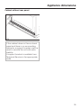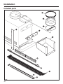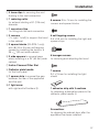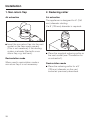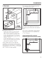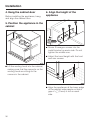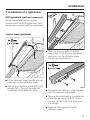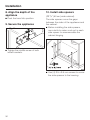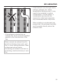
1
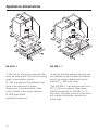
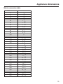
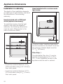
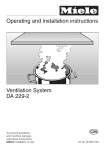
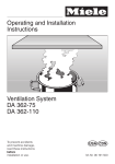
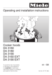
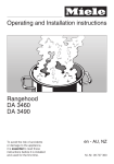
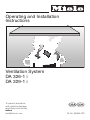
Operating and Installation
Instructions
Ventilation System
DA 326-1 i
DA 329-1 i
To prevent accidents
and machine damage,
read these instructions
before
installation or use.
UV
M.-Nr. 05 864 020
2
Contents
IMPORTANT SAFETY INSTRUCTIONS . . . . . . . . . . . . . . . . . . . . . . . . . . . . . . . . . 4
Guide to the hood . . . . . . . . . . . . . . . . . . . . . . . . . . . . . . . . . . . . . . . . . . . . . . . . . 8
Functional description . . . . . . . . . . . . . . . . . . . . . . . . . . . . . . . . . . . . . . . . . . . . 10
Operation . . . . . . . . . . . . . . . . . . . . . . . . . . . . . . . . . . . . . . . . . . . . . . . . . . . . . . . 11
Turning the fan on . . . . . . . . . . . . . . . . . . . . . . . . . . . . . . . . . . . . . . . . . . . . . . . . . 11
Selecting the power level . . . . . . . . . . . . . . . . . . . . . . . . . . . . . . . . . . . . . . . . . . . 11
Turning the fan off . . . . . . . . . . . . . . . . . . . . . . . . . . . . . . . . . . . . . . . . . . . . . . . . . 11
Turning the light on . . . . . . . . . . . . . . . . . . . . . . . . . . . . . . . . . . . . . . . . . . . . . . . . 12
Turning the light off . . . . . . . . . . . . . . . . . . . . . . . . . . . . . . . . . . . . . . . . . . . . . . . . 12
Cleaning and care . . . . . . . . . . . . . . . . . . . . . . . . . . . . . . . . . . . . . . . . . . . . . . . . 13
Cleaning the casing . . . . . . . . . . . . . . . . . . . . . . . . . . . . . . . . . . . . . . . . . . . . . . . . 13
Grease filter . . . . . . . . . . . . . . . . . . . . . . . . . . . . . . . . . . . . . . . . . . . . . . . . . . . . . . 13
Inserting / replacing the active charcoal filters . . . . . . . . . . . . . . . . . . . . . . . . . . . 16
Changing the light bulbs . . . . . . . . . . . . . . . . . . . . . . . . . . . . . . . . . . . . . . . . . . . . 17
After Sales Service . . . . . . . . . . . . . . . . . . . . . . . . . . . . . . . . . . . . . . . . . . . . . . . 18
Installation instructions . . . . . . . . . . . . . . . . . . . . . . . . . . . . . . . . . . . . . . . . . . . 19
IMPORTANT SAFETY INSTRUCTIONS . . . . . . . . . . . . . . . . . . . . . . . . . . . . . . . . 20
Electrical data. . . . . . . . . . . . . . . . . . . . . . . . . . . . . . . . . . . . . . . . . . . . . . . . . . . . 21
Appliance dimensions . . . . . . . . . . . . . . . . . . . . . . . . . . . . . . . . . . . . . . . . . . . . . 22
Installation . . . . . . . . . . . . . . . . . . . . . . . . . . . . . . . . . . . . . . . . . . . . . . . . . . . . . . 26
1. Non-return flap . . . . . . . . . . . . . . . . . . . . . . . . . . . . . . . . . . . . . . . . . . . . . . . . . . 28
2. Reducing collar . . . . . . . . . . . . . . . . . . . . . . . . . . . . . . . . . . . . . . . . . . . . . . . . . 28
3. Runners . . . . . . . . . . . . . . . . . . . . . . . . . . . . . . . . . . . . . . . . . . . . . . . . . . . . . . . 29
4. Hang the cabinet door . . . . . . . . . . . . . . . . . . . . . . . . . . . . . . . . . . . . . . . . . . . . 30
5. Position the appliance in the cabinet. . . . . . . . . . . . . . . . . . . . . . . . . . . . . . . . . 30
6. Align the height of the appliance . . . . . . . . . . . . . . . . . . . . . . . . . . . . . . . . . . . . 30
7. Installation of a lightshield . . . . . . . . . . . . . . . . . . . . . . . . . . . . . . . . . . . . . . . . . 31
8. Align the depth of the appliance . . . . . . . . . . . . . . . . . . . . . . . . . . . . . . . . . . . . 32
9. Secure the appliance. . . . . . . . . . . . . . . . . . . . . . . . . . . . . . . . . . . . . . . . . . . . . 32
10. Install side spacers . . . . . . . . . . . . . . . . . . . . . . . . . . . . . . . . . . . . . . . . . . . . . 32
11. Spacer strip for the rear of the appliance . . . . . . . . . . . . . . . . . . . . . . . . . . . . 33
12. Light cover . . . . . . . . . . . . . . . . . . . . . . . . . . . . . . . . . . . . . . . . . . . . . . . . . . . . 34
13 a. Air extraction mode. . . . . . . . . . . . . . . . . . . . . . . . . . . . . . . . . . . . . . . . . . . . 35
13 b. Recirculation mode. . . . . . . . . . . . . . . . . . . . . . . . . . . . . . . . . . . . . . . . . . . . 35
14. Electrical connection . . . . . . . . . . . . . . . . . . . . . . . . . . . . . . . . . . . . . . . . . . . . 36
Air extraction . . . . . . . . . . . . . . . . . . . . . . . . . . . . . . . . . . . . . . . . . . . . . . . . . . . . 38
Caring for the environment . . . . . . . . . . . . . . . . . . . . . . . . . . . . . . . . . . . . . . . . . 40
3
IMPORTANT SAFETY INSTRUCTIONS
Read these Operating Instructions carefully before installing or
using the Ventilation System.
This appliance is intended for
residential use only. Use the
appliance only for its intended
purpose. The manufacturer cannot
be held responsible for damages
caused by improper use of the
hood.
This appliance complies with current
safety requirements. Improper use of
the appliance can lead to personal
injury and material damage.
READ AND SAVE THESE
INSTRUCTIONS
CAUTION
For General Ventilating Use Only.
Do Not Use To Exhaust Hazardous
Or Explosive Materials And Vapors.
This appliance is designed to vent
cooking smoke and odors only.
Be certain your appliance is
properly installed and grounded by
a qualified technician.
To guarantee the electrical safety of this
appliance, continuity must exist
between the appliance and an effective
grounding system. It is imperative that
this basic safety requirement be met. If
there is any doubt, have the electrical
system of the house checked by a
qualified electrician. The manufacturer
can not be held responsible for
damages caused by the lack, or
inadequacy of, an effective grounding
system.
Before connecting the appliance to
the power supply make sure that
the voltage and frequency listed on the
data plate correspond with the
household electrical supply. This data
must correspond to prevent machine
damage. Consult a qualified electrician
if in doubt.
Installation work and repairs should
only be performed by a qualified
technician in accordance with all
applicable codes and standards.
Repairs and other work by unqualified
persons could be dangerous and the
manufacturer will not be held
responsible.
4
IMPORTANT SAFETY INSTRUCTIONS
This equipment is not designed for
maritime use or for use in mobile
installations such as caravans or
aircraft. However, under certain
conditions it may be possible for an
installation in these applications. Please
contact the nearest Miele dealer or the
Technical Service Department with
specific requirements.
Before servicing or cleaning the
unit, switch power off at the service
panel and lock the service
disconnecting means to prevent power
from being switched on accidentally.
When the service disconnecting means
can not be locked, securely fasten a
prominent warning device, such as a
tag, to the service panel.
Before discarding an old
appliance, unplug it from the
power supply and remove the power
cord and any doors to prevent hazards.
Use
Do not allow children to play with
or operate the appliance or its
controls. Supervise its use by the
elderly or infirm.
Be careful when preparing a
flambé beneath the hood.
Flames may be drawn up into the hood
by the suction or grease filters may
catch fire.
Never operate gas burners without
pots.
Do not leave cooking surfaces
unattended while in use.
Overheated food, oil and grease can
catch fire.
Do not use the hood without the
grease filters in place.
Clean the grease filters regularly.
Dirty filters are a fire hazard.
Do not use a steam cleaner to
clean the hood. Steam could
penetrate electrical components and
cause a short circuit.
Always turn on the hood when
using the cooktop to prevent
damage from condensation.
5
IMPORTANT SAFETY INSTRUCTIONS
, WARNING - TO REDUCE
THE RISK OF A RANGE TOP
GREASE FIRE:
Never leave surface units
unattended at high settings.
Boilovers cause smoking and greasy
spillovers may ignite. Heat oils slowly
on low or medium settings.
Always turn the hood “ON” when
cooking at high heat or when
cooking flaming foods.
Clean ventilating fans frequently.
Grease should not be allowed to
accumulate on the fan or filter.
Use proper pan size. Always use
cookware appropriate for the size
of the surface element.
, WARNING
TO REDUCE THE RISK OF INJURY
TO PERSONS IN THE EVENT OF A
RANGE TOP GREASE FIRE,
OBSERVE THE FOLLOWING:
SMOTHER FLAMES with a close
fitting lid, cookie sheet, or metal
tray, then turn off the burner.
BE CAREFUL TO PREVENT BURNS.
If the flames do not go out immediately,
EVACUATE AND CALL THE FIRE
DEPARTMENT.
NEVER PICK UP A FLAMING
PAN - You may be burned.
DO NOT USE WATER, including
wet dishcloths or towels - a violent
steam explosion will result.
Use an extinguisher
ONLY if:
– You know you have a Class ABC
extinguisher, and you already know
how to operate it.
– The fire is small and contained in the
area where it started.
– The fire department is being called.
– You can fight the fire with your back
to an exit.
6
IMPORTANT SAFETY INSTRUCTIONS
Installation
, WARNING
To reduce the risk of fire only
use metal ductwork.
When installing the hood, follow the
recommended minimum safety
distances between a Miele cooktop and
the hood:
– 22" (55 cm) above electric cooktops,
– 26" (65 cm) above gas cooktops,
– 26" (65 cm) above an open grill.
If local building codes require a greater
safety distance, follow their
requirement.
For non-Miele cooking appliances
maintain the safety distances
recommended by the appliance
manufacturer in their instructions.
If there is more than one appliance
beneath the hood and they have
different minimum safety distances
always select the greater distance.
Be careful not to damage hidden
electrical wiring or plumbing when
cutting or drilling into the wall or ceiling.
Any fittings, sealant, or materials
used to install the ductwork must
be made of approved non-flammable
materials.
Never connect an exhaust hood to
an active chimney, dryer vent, vent
flue, or room ventilating ductwork. Seek
professional advice before connecting
an exhaust hood vent to an existing,
inactive chimney or vent flue.
Ducted fans must always be
vented outdoors.
Make sure that the airflow in the
room is sufficient for combustion
and exhausting of all non-electric
heating appliances (water heaters, gas
cooktops, gas ovens, etc.), otherwise
backdrafts may occur. Follow the
heating manufacturer’s guidelines and
safety standards or those published by
the National Fire Protection Association
(NFPA), or the American Society for
Heating, Refrigeration and Air
Conditioning Engineers (ASHRAE).
If in doubt, consult an experienced
professional.
Do not use an extension cord to
connect the appliance to electricity.
Extension cords do not guarantee the
required safety of the appliance, (e.g.
danger of overheating).
Do not install this hood over
cooktops burning solid fuel.
7
Guide to the hood
8
Guide to the hood
a Vent connection
i Light button
b Active charcoal filter slot
j On/Off button
c Control panel
k Power level buttons
d Pull-out
deflector plate
Four fan speed selection
e DFB Facia Panel
(must be ordered separately)
f Internal grease filter
g Overhead cooktop light
h External grease filter
9
Functional description
The hood offers two modes of
operation:
Air extraction
Recirculation mode
The air is drawn in and cleaned by the
grease filters and directed outside.
Air is drawn through the grease filters
and an active charcoal filter. The
filtered air is then recirculated back into
the kitchen through a vent at the top of
the hood’s chimney.
The hood comes equipped with a
non-return flap. This flap automatically
closes when the hood is turned off so
that no exchange of outside air and
room air can occur. When the hood is
turned on, the air pressure of the
exhaust fan automatically opens the
flap blowing the inside air and cooking
odors outside.
10
Before using the hood in
recirculation mode, ensure that the
active charcoal filters are in place,
see "Cleaning and care".
Operation
Turning the fan on
Fan performance
^ Pull the deflector plate out about 2"
(5 cm).
The maximum air flow capacity is
625 cfm. Factors such as narrow duct
diameter and bends will affect this
value.
The hood will operate at power level "II".
Selecting the power level
Depending on how much the air needs
to be filtered, there are four power
levels available.
For normal cooking a low to medium
level is usually sufficient.
For frying or cooking food with a strong
aroma use the highest level.
There will also be a slight decrease in
airflow for hoods operated in
recirculation mode due to the active
charcoal filter.
Level 1 operates at 40% capacity
Level 2 operates at 60% capacity
Level 3 operates at 80% capacity
Level 4 operates at 100% capacity
Turning the fan off
Lower
Higher
^ Use the power level buttons to select
the power level required.
The indicators show which power level
has been chosen.
^ Press the On/Off button to turn the
fan off.
or
^ Push the deflector plate back in.
The next time the deflector plate is
pulled out the hood will operate at
power level "II".
11
Operation
Turning the light on
Turning the light off
The light for illuminating the cooktop
can be turned on or off independently
of the fan.
^ Press the light button again.
^ Pull the deflector plate out 1.5"
(3 cm).
^ Push the deflector plate back in.
^ Press the light button.
^ When the light is turned on the
indicator next to the button
illuminates
12
or
The next time the deflector plate is
pulled out the light will come back on.
Cleaning and care
Stainless steel surfaces
Before servicing or cleaning the
hood, disconnect it from the power
supply by "tripping" the circuit
breaker or unplugging it.
Make sure power is not restored to
the appliance while maintenance or
repair work is performed.
Cleaning the casing
Never use abrasive cleaners,
scouring pads, steel wool or caustic
(oven) cleaners on the hood. They
will damage the surface.
^ All external surfaces and controls can
be cleaned with warm water and
liquid dish soap applied with a soft
sponge.
^ Wipe dry using a soft cloth.
Stainless steel surfaces can be cleaned
using a non-abrasive stainless steel
cleaner.
To help prevent resoiling, a conditioner
for stainless steel can be applied.
Grease filter
The reusable metal grease filters
remove solid particles from the vented
kitchen air like grease and dust, etc.
The hood has an external filter which
is visible from beneath. An internal
filter is situated above the external filter
within the casing.
The grease filters should be cleaned
every 3-4 weeks or whenever the
grease filter indicator lights.
Always clean both filters.
Dirty filters are a fire hazard.
Do not use too much water when
cleaning the controls. Water could
penetrate the electronics and cause
damage.
13
Cleaning and care
Removing the filters
External filter
^ To remove the external filter pull the
deflector plate out slightly.
^ Turn the fan off.
^ Holding the external filter at the front
tilt it approximately 1" (3 cm)
downwards and then pull it towards
you to remove.
Internal filter
^ Pull the deflector plate out to its full
extension.
The internal filter will now be visible.
^ Cleaning the filters
– by hand: with a nylon brush in a mild
solution of warm water and liquid
soap.
– in a dishwasher: place the filters
vertically in the lower basket,
checking that the spray arm is not
blocked.
^ DA 329-1 i
The external grease filter can be
folded and cleaned in the dishwasher
by turning the latches as shown.
Depending on the detergent,
cleaning the grease filters in a
dishwasher may cause permanent
discoloration of the filter surface.
Performance of the filter will not be
affected by this discoloration.
^ After cleaning, the filters can be
placed on a towel to air dry.
^ While the filters are removed, clean
any dirt or grease from the filter
casing to prevent the risk of fire.
^ Holding it by the handle pull it
downwards to remove.
14
Cleaning and care
Inserting the filters
Internal filter
^ Fit the filter into the appliance so that
it hooks into position at the back then
push it up at the front and make sure
it engages in position on the left and
right hand sides.
^ Make sure that the red plastic
guides are at the front and facing up.
External filter
^ Insert the external filter into the
extended deflector plate and hold it
in position.
^ Tilt the rear of the filter up and gently
push until it snaps into place.
^ DA329-1 i:
Turn the grease filter latches as
shown. Unfold the grease filter and
lock the latches.
15
Cleaning and care
Inserting / replacing the active
charcoal filters
^ Replace the filter every 6 months or
when it is no longer absorbing
cooking odors.
Replacement active charcoal filters
can be ordered from Technical
Service.
USA 1-800-999-1360
CDN 1-800-565-6435
Please quote part # 05 182 190.
Follow the instructions supplied with the
active charcoal filter.
For recirculation mode an active
charcoal filter must be used in addition
to the grease filters. The charcoal filters
are designed to absorb cooking odors.
The active charcoal filter is inserted into
the slot on the front of the appliance.
16
Dispose of the charcoal filter with the
household waste.
Cleaning and care
Changing the light bulbs
^ Lower the cover to remove it.
If the light does not work the bulb may
need to be replaced or the starter could
be defective.
^ Replace the fluorescent bulb or the
starter.
^ Remove the external filter as
described in "Removing the filters".
^ Secure the cover in position with the
fixing screws.
^ Return the external filter.
^ Unscrew the fixing screws on the
right and left hand sides of the light
cover. While undoing the screws hold
the cover securely so that it does not
drop on to the cooktop below.
17
After Sales Service
In the event of a fault which you can not
correct yourself please contact the
Miele Technical Service Department
U
1-800-999-1360
[email protected]
V
1-800-565-6435
[email protected]
When contacting the Technical Service
Department, please quote the model
and serial number of your appliance.
These are shown on the data plate
which is visible when the grease filter is
removed.
18
Installation Instructions
IMPORTANT SAFETY INSTRUCTIONS
Do not install this exhaust hood over
cooktops burning solid fuel.
When installing the hood, make sure
that the following minimum
distance (S) between the top of a
Miele cooking surface and the
bottom of the hood is:
- 18" (45 cm) above electric
cooktops
- 26" (65 cm) above gas cooktops
- 26" (65 cm) above an open grill
For non-Miele cooking appliances
maintain the safety distances
recommended by the cooktop
manufacturer in their instructions.
Obey local building codes.
If there is more than one appliance
beneath the hood and they have
different minimum safety distances
always select the greater distance.
See "Important Safety Instructions"
for further information.
20
If there is any doubt concerning
installation, contact the Technical
Service Department.
USA 1-800-999-1360
[email protected]
CDN 1-800-565-6435
[email protected]
,During the installation process,
please be careful of sharp edges
that can cause harm.
Electrical data
All electrical work should be
performed by a qualified electrician
in strict accordance with national
and local safety regulations.
Installation, repairs and other work
by unqualified persons could be
dangerous. The manufacturer can
not be held responsible for
unauthorized work.
Ensure that power to the appliance
is "OFF" while installation or repair
work is performed.
Verify that the voltage, load and circuit
rating information found on the data
plate (located behind the grease filter),
match the household electrical supply
before installing the hood.
Important
The hood comes equippped with a 5 ft
(1.5 m) power cord with a NEMA 5-15
molded plug for connection to a
120 VAC, 60 Hz, 15 A power outlet.
Maximum load
– DA 326-1 i. . . . . . . . . . . . . . . . . 365 W
– DA 329-1 i. . . . . . . . . . . . . . . . . 366 W
Light
– DA 326-1 i . . . . . . . . . . . . . . . 1 x 15 W
– DA 329-1 i . . . . . . . . . . . . . . . 1 x 16 W
Voltage . . . . . . . . . . . . . . . . . . . . . 120 V
Frequency . . . . . . . . . . . . . . . . . . 60 Hz
Circuit rating. . . . . . . . . . . . . . . . . . 15 A
If there is any question concerning the
electrical connection of this appliance
to your power supply, please consult a
licensed electrician or call Technical
Service.
USA 1-800-999-1360
CDN 1-800-565-6435
WARNING:
THIS APPLIANCE MUST BE
GROUNDED
21
Appliance dimensions
DA 326-1 i
DA 329-1 i *
1) The slot for the active charcoal filter
must be accessible if the hood is being
used in recirculation mode.
To ensure that the exhaust ducting can
be installed on the exhaust connection
easily, the upper cabinet must be at
least 18 1/8" (460 mm) high.
2) The rear panel of the cabinet may
have to be removed for these
dimensions to be applicable. (See
built-in depth of the upper cabinet).
3) DFB light shield
(optional accessory)
22
*The DA 329-1 i can also be built into a
23 5/8" (60 cm) cabinet. (See upper
cabinet measures for DA 326-1 i). In
this case, the lower portion of the hood
will overlap the bottom cabinets on
either side.
Appliance dimensions
Metric conversion table
Millimeters
Inches
3
1
/8
10
3
/8
15
9
19
3
30
3
1 /16
40
1 9/16
50
1 15/16
70
2 3/ 4
75
3
85
3 3/ 8
88
3 1/ 2
125
5
/16
/4
150
6
170
11
6
/16
175
6 7/ 8
190
7 1/ 2
245
9 5/ 8
255
10 1/16
258
10 3/16
270
10 5/8
273
10 3/4
275
10 13/16
285
11 1/4
345
13 9/16
420
16 9/16
460
18 1/8
470
18 1/2
562
22 1/8
568
22 3/8
595
23 7/16
600
23 5/8
895
35 1/4
900
35 7/16
23
Appliance dimensions
Installation in cabinetry
The depth of the installation depends
on what type of light shield is used and
the dimensions of surrounding
cabinetry.
Hood installed with a custom made
light shield
Hood installed with a DFB light
shield (optional accessory)
To install the hood so that the light
shield is flush with the adjacent
cabinetry, the following dimensions
must be used. (Please refer to the
metric conversion table)
A custom made, matching light shield
can be mounted on the hood. To do this
the minimum cabinet depth must be
10 13/16" (275 mm).
Filler Strip a
The adjustable filler strip a can be
used to conceal gaps of 3/8" to 2 3/4"
(10 - 70 mm) between the rear of the
appliance and the wall or cabinet.
– A minimum cabinet depth of 10 3/4"
(273 mm) when using a 5/8" (16 mm)
thick door panel
– A minimum cabinet depth of 10 5/8"
(270 mm) when using a 3/4" (19 mm)
thick door panel
24
Appliance dimensions
Cabinet without rear panel
If the cabinet does not have a back
panel and there is no surrounding
cabinetry a support bracket must be
used to provide the unit with extra
stability.
A support bracket is available from
Technical Service in the appropriate
width.
25
Installation
Included parts
26
Installation
a 2 hose clips for securing the vent
ducting to the vent connection
b 1 reducing collar
for exhaust ducting of 5" (125 mm)
diameter
8 screws 3.5 x 16 mm for installing the
runners and spacer blocks
c 1 non-return flap
for fitting into the vent connection
d 2 runners
(1 x right, 1x left) to support the hood
in the cabinet
6 self-tapping screws
3.5 x 9.5 mm for installing the light and
spacer strips
e 2 spacer blocks (DA 329i-1 only)
with (8) 3.5 x 9.5 mm self-tapping
screws for installing the hood in a
35 7/16" (90 cm) wide cabinet
f 2 side spacers to conceal gaps
when installing in a 24" (60 cm) wide
cabinet
6 hexagon screws
for securing and adjusting the hood
g Active Charcoal Filter Slot
h Deflector plate handle
for the front panel
i 1 spacer strip to conceal the gap
between the rear of the appliance
and the wall
j 1 light cover
with right and left holders k.
7 screws
3.0 x 15 mm for installing the light
shield
1 adhesive strip with 3 sections
for attaching a decorative piece to the
deflector plate handle i
Screwdriver
for aligning the cabinet door after the
appliance has been installed
27
Installation
1. Non-return flap
2. Reducing collar
Air extraction
Air extraction
The appliance is designed for 6" (150
mm) diameter ducting.
If a 5" (125 mm) diameter is required:
^ Insert the non-return flap into the vent
socket so the flaps open upward.
(This is not necessary if the ducting
system is already fitted with a non
return flap, e.g. wall vent).
Recirculation mode
When used in recirculation mode a
non-return flap it is not necessary.
28
^ Place the supplied reducing collar on
the vent socket (see "Connection for
air extraction").
Recirculation mode
^ Place the reducing collar for a 5"
(125 mm) diameter on the vent
socket as previously described.
Installation
3. Runners
The measure "x" will depend on the
type of lightshield used.
The Miele DFB lightshield (optional
accessory) sits flush with the cabinet
front.
^ Cabinet width 60 cm:
Install the runners on the left and
right side of the cabinet with (4)
3.5 x 16 mm screws on each side.
If the side panels are 5/8" (16 mm)
thick, use the bracket side with the
marker "16 mm".
If the side panels are 3/4" (19 mm)
thick, turn the bracket and use the
side with the marker "19 mm".
The runner’s adjustable range allows
the hood position to be adjusted by
± 9/16" (15 mm).
Hood installed with a cabinet
matching light shield (custom made)
Note: Please refer to the "Special
installation instructions" at the end of
this section for instructions on installing
the appliance into a 27 9/16" (70 cm) or
35 7/16" (90 cm) wide cabinet.
29
Installation
4. Hang the cabinet door
Before installing the appliance, hang
and align the cabinet door.
6. Align the height of the
appliance
5. Position the appliance in the
cabinet
^ Screw 3 hexagon screws into the
install bracket on each side. Do not
tighten the middle one.
^ Adjust the hood height with the front
and rear screws.
^ Lift the venting hood into the cabinet,
making sure that the supports on the
venting hood are sitting on the
runners in the cabinet.
^ Align the appliance at the lower edge
of the cabinet side panels so that a
gap of 1/8" (3 mm) is left on each
side.
30
Installation
7. Installation of a lightshield
DFB lightshield (optional accessory)
Follow the installation instructions
supplied with the DFB lightshield. Use
the screws supplied with the lightshield.
Custom made lightshield
^ Stick the three lengths of double
sided tape to the custom lightshield
and stick it to the deflector plate
handle as shown above.
^ Fit the deflector plate handle into the
openings on the deflector plate.
^ Secure the handle in place with the 2
screws (3.0 x 15 mm) through the
underside of the deflector plate.
^ Dismantle the deflector plate handle
with the attached lightshield.
^ Secure the lightshield to the deflector
plate handle using (5) 3.0 x 15 mm
screws, two at either side and one in
the middle.
^ Reattach the lightshield to the
deflector plate.
31
Installation
8. Align the depth of the
appliance
^ Push the hood into position.
9. Secure the appliance
10. Install side spacers
(23 5/8" (60 cm) wide cabinet)
The side spacers cover the gaps
between the sides of the appliance and
the cabinet.
^ Before installing the side spacers,
use a knife to make a cut-out in each
side spacer to accommodate the
cabinet hinging.
^ Tighten the middle screw of both
install brackets.
^ Use (4) 3.5 x 9.5 mm screws to screw
the side spacers to the housing.
32
Installation
11. Spacer strip for the rear of
the appliance
^ Insert the spacer strip to the
underside of the appliance.
^ Measure the gap "T" between the rear
of the appliance and the wall.
^ Turn the side cover caps upwards
and press into position.
^ Use a knife to trim the supplied
spacer strip to measurement "T".
33
Installation
12. Light cover
Reinserting the external filter:
^ Pull the deflector plate slightly out.
^ Remove the protective film from the
the filter frame.
^ Tilt the front of the external filter
slightly down and out.
^ Make sure that the red plastic guides
are at the front and facing up.
^ Insert the two holders on to the sides
of the light cover.
^ Insert the external filter into the
extended deflector plate from below
and hold it in position.
^ Push the filter gently upwards and
push the deflector plate in. The filter
will slide into the holders.
^ Secure the light cover using (2)
3.5 x 9.5 mm self-tapping screws.
34
^ Push the filter backwards so it snaps
into place.
Installation
13 a. Air extraction mode
13 b. Recirculation mode
If the hood can not be installed for air
extraction the appliance must be
connected for recirculation mode.
The following parts, available through
your Miele Dealer or the Miele Technical
Service Department are necessary for
using the appliance in recirculation
mode:
^ Insert the panel supplied into the
Active Charcoal Filter slot.
^ Secure the ventilation ducting over
the vent socket of the hood using a
hose clip.
– Air Recirculation Conversion kit 5"
(125 mm) diameter. Includes an
exhaust grill, flexible ducting, and a
hose clip.
– Active Charcoal Filter.
^ Complete venting installation. (See
"Air extraction").
35
Installation
Connection for recirculation mode
^ Install the Active Charcoal Filter (see
"Cleaning and care").
^ The exhaust grill b must be fitted in
the top of the unit.
If the front of the hood is installed at
ceiling height then a cut-out must be
made in the front panel.
When installing the ventilation grill
make sure that the slats in the grill
point towards the center of the room
and not towards a wall or the ceiling.
^ The vent connection (vent socket) a
and the exhaust grill b must be
joined together with a pipe or flexible
duct c cut to size.
36
14. Electrical connection
Refer to the notes in "Electrical
connection" and "Important Safety
Instructions" before connecting to
electricity.
^ Plug in the power cord.
Installation
Special installation
instructions
27 9/16" (70 cm) width cabinet
35 7/16" (90 cm) width cabinet
^ The measure "x" will be calculated as
described for a 23 5/8" (60 cm)
cabinet.
^ Screw the spacer block to the
cabinet using 4.0 x 16 mm screws
with the lower edge flush with the
cabinet.
^ Screw the runners according to the
thickness of the cabinet walls with
either the imprint "16 mm" or "19 mm"
to the spacer blocks using 3 self
tapping screws 3.5 x 9.5 mm on each
side.
^ Insert the supplied 3.5 x 9.5 mm
screws to cover the 4 drill holes in the
casing.
37
Air extraction
Danger of toxic fumes.
Gas cooking appliances release
carbon monoxide that can be
harmful or fatal if inhaled. The
exhaust gases extracted by the
hood should be vented outside of
the building only.
Do not terminate the exhaust
ducts in attics, garages,
crawlspaces, etc.
Please read and follow the "Important
Safety Instructions" to reduce the risk
of personal injury, and follow all local
building codes when installing the
hood.
WARNING
To reduce the risk of fire, Use only
metal ductwork.
CAUTION
To reduce risk of fire and to properly
exhaust air, be sure to duct air
outside - Do not vent exhaust air into
spaces within walls or ceilings or
into attics, crawl spaces, or garages.
– Use smooth or flexible pipes made
from approved non-flammable
materials for exhaust ducting.
Exhaust ducting and connections
– Where the ductwork is horizontal, it
must slope away from the hood at
least 1/8" per foot (1cm per meter) to
prevent condensation dripping into
the appliance.
– The ducting should be as short and
straight as possible, and the number
of sharp bends should be minimized.
– If the exhaust is ducted through an
outside wall, a Miele Telescopic Wall
Vent can be used.
– For most efficient air extraction, the
diameter of the ductwork should not
be less than 6" (150 mm). Use of flat
ducts also reduces the air extraction
efficiency.
– Noise levels of the hood will increase
if flat ducts or round ducts of less
than 6" (150 mm) in diameter are
used.
38
Air extraction
– If the ductwork runs through rooms,
ceilings, garages, etc. where
temperature variations exist, it may
need to be insulated to reduce
condensation. In some cases, a
condensate trap may also be
required to collect and evaporate
any condensate which may occur.
When installing a condensate trap,
ensure that it is positioned vertically
and if possible directly above the
exhaust outlet.
– If the exhaust is ducted into an
inactive flue, the air must be expelled
parallel to the flow direction of the
flue.
Never connect an exhaust hood to
an active chimney, dryer vent, vent
flue, or room venting ductwork. Seek
professional advice before
connecting an exhaust hood vent to
an existing, inactive chimney or vent
flue.
39
Caring for the environment
Disposal of packing material
Disposal of an old appliance
The cardboard box and packing
materials protect the appliance during
shipping. They have been designed to
be biodegradable and recyclable.
Please recycle.
Old appliances may contain materials
that can be recycled. Please contact
your local recycling authority about the
possibility of recycling these materials.
To prevent suffocation of children,
ensure that any plastic wrappings,
bags etc. are disposed of safely and
kept out of their reach.
40
Before discarding an old hood,
unplug it from the outlet and cut off
its power cord to prevent hazards.
41
42
43
Alteration rights reserved / 1604
This paper was bleached without the use of chlorine.
M.-Nr. 05 864 020 / 05