1
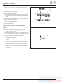
System software for control and monitoring of refrigeration plant AKM / AK-Monitor / AK-Mimic Installation guide Contents Introduction This installation guide will give you instructions as regards: - what can be connected to the PC ports - how the programme is installed - how the ports are set - how the frontend is connected - how router lines are set Included as appendices: 1 - Communication via Ethernet 2 - Router lines and system addresses 3 - Application examples The instructions end when you can communicate with all units in the system. The continued setup will be described in the manual. Check list for installation This summary is intended for the experienced installer who has already installed ADAP-KOOL® refrigeration controls on earlier occasions. (Appendix 3 may also be used). 1. All controllers must be installed. An address must be set for each controller. 2. The data communication cable must be connected to all the controllers. The two controllers at either end of the data communication cable must be terminated. 3. Connect to frontend • Gateway Use the AKA 21 for setting • AK-SM Use the AK-ST for setting • AK-SC 255 Use front panel or the AKA 65 for setting • AK-CS /AK-SC 355 Use front panel or a Browser for setting 4. Install the programme on the PC. Among other things: Set the system address in the programme (yyy:zzz) e.g 51:124 Set communication ports 5. Import any description files for controllers. 6. Upload data from the network - ”Net configuration” from the AK-Frontend - ”Description” from the controllers. 7. Proceed with the arrangement as to how the system should be shown in the programme (See Manual) 2 Options..........................................................................................3 AK Monitor / AK-Mimic........................................................................... 3 AKM4 / AKM5.............................................................................................. 3 1. Prior to installation...................................................................4 2. Installation of the programme on the PC...............................5 Procedure..................................................................................................... 5 Setup display............................................................................................... 5 PC setup........................................................................................................ 5 Show Communication trace.................................................................. 5 Button for Port Setup............................................................................... 7 Button for Router Setup (via AKA only)............................................. 7 Printouts........................................................................................................ 8 System Setup / Language....................................................................... 8 Start the AKM programme through the PC..................................... 8 Alarm.............................................................................................................. 8 Log.................................................................................................................. 8 Optimize communication....................................................................... 8 Button for Print........................................................................................... 8 Button for Advanced................................................................................ 8 3. First time the programme is started.......................................9 Setting........................................................................................................... 9 4. Connection to AK-SC 255, AK-SC 355, AK-CS, AK-SM 720 / 350.10 Introduction...............................................................................................10 Setting.........................................................................................................10 5. Connect to AKA - gateway.....................................................12 Principle......................................................................................................12 Setting.........................................................................................................12 6. Upload controller data...........................................................14 Principle......................................................................................................14 Setting.........................................................................................................14 7. Resume....................................................................................15 Appendix 1 - Routing via Ethernet (for AKA only)...................16 Principle......................................................................................................16 1. Setup of TCP/IP converter................................................................16 2. Connection............................................................................................17 3. Set port on AKA 245...........................................................................17 4. Set router lines.....................................................................................17 5. Speed.......................................................................................................18 Appendix 2 - Router lines...........................................................19 Principle......................................................................................................19 Receivers.....................................................................................................19 How?.............................................................................................................19 Appendix 3 - Application examples (for AKA only).................21 Introduction...............................................................................................21 Preparation of system for data communication...........................22 Preparation of a central PC...................................................................23 First communication to a plant from a central PC.......................25 Initial settings of AKC controllers in a plant from a central PC................................................................................................27 Change of setting in a controller from a PC...................................28 Installation guide RI8BP602 © Danfoss 10/2011 AKM/AK Monitor/AK Mimic Options AK Monitor / AK-Mimic AKM4 / AKM5 AK Monitor is the programme with a few easy-to-use functions. The programme gives you an overview of temperatures and alarms in the local refrigerating plant. The AK-Mimic has a graphic user interface. AKM is the programme with many functions. The programme gives you an overview of all functions in all connected refrigerating systems. The programme is used by service centres or in systems where more functions are required than can be obtained with AK Monitor. The AKM5 has a graphic user interface. TCP/IP Example Example An example is shown here from a food store. A number of control lers regulate the individual refrigeration points. The modem gateway collects data from each of the refrigeration points and transfers these data to the PC with the AK Monitor or to a service centre via the modem connection. Alarms are transmitted to the PC during the shop’s opening hours and to the service centre outside of opening hours. AKM/AK Monitor/AK Mimic Here you can see a service centre with connections to other systems: - A gateway is connected to Com 1. The Gateway acts as a buffer when alarm buffer when alarms come in from external systems. - A modem is connected to Com 2. This calls the various systems that undertake service. - A GSM modem is connected to Com 3. Alarms are sent from here to a mobile telephone. - A converter is connected from Com 4 to a TCP/IP. From here there is access to external systems. - There is also access to the TCP/IP from the computer net card and on from there via Winsock. Installation guide RI8BP602 © Danfoss 10/2011 3 1. Prior to installation AKA 245 / AKA 241 There are different types of gateways. They can all be used as connecting point for the PC, but sometimes it is enough to use the somewhat smaller gateway type AKA 241. Different ways of making connections are illustrated in Appendix 3. Use the way that is best suited for your plant. Use the AKA 21 to set: - Type of usage = PC-GW, Modem-GW or IP-GW - Network - Address - Areas for Lon-addresses - RS 232 port speed AK-SM 720 The system unit must be connected either to Ethernet or a modem. Use the AK-ST service tool to set: - IP address or telephone number - Destination - Access code AK-SM 350 The system unit must be connected either to Ethernet or a modem. Use either the front panel or the AK-ST service tool to set: - IP address or telephone number - Destination - Access code AK-SC 255 The system unit must be connected to Ethernet. Use either the front panel or the AKA 65 software to set: - IP address - Authorisation code - Account code - Alarm port AK-CS /AK-SC 355 The system unit must be connected to Ethernet. Use either the front panel or Browser to set: - IP address - Authorisation code - Account code - Alarm port Requirements to the PC - Pentium 4, 2.4 GHz - 1 or 2 GB RAM - 80 GB Harddisk - CD-ROM drev - Windows XP Professional version 2002 SP2 (32 bit) - Windows 7 Home Premium (32 bit) - The PC type must be contained in Microsoft’s positive list for Windows. - Net card to Ethernet if external TCP/IP contact is required - Serial port for connection of gateway, modem, TCP/IP converter A hardware handshake is required between the PC and the gateway. A 3 m long cable between the PC and the gateway may be ordered from Danfoss. If a longer cable is required (but max. 15 m), this can be made based on the diagrams shown in the gateway manual. - There must be more serial ports in the PC if more connections are required. If a GSM modem (telephone) is connected directly to the PC’s Com.port, the modem must be a Siemens type MC35i or TC35i or Cinterion Type MC52iT or MC55iT. This modem has been tested for its application and found to be OK. - Windows printer - This HASP-key must be placed in the PC’s port before the programme can be used. Requirements to software - MS Windows 7 or XP must be installed. - The programme will require a free disk capacity of at least 80 GB to allow it to be installed, (i.e. 80 GB free capacity when WINDOWS has been started). - If alarms are routed via email or Windows 7 is used, Outlook or Outlook Express must be installed. - Installing programmes other than Windows or AKM is not recommended. - If a firewall or other anti-virus programme is installed, they must accept AKM functions. Change of software version Before upgrade is commenced, a backup should be made of the existing version. If the installation of the new version does not work out as planned, the earlier version can be reinstalled. The new AKM must be stored in the same file as the previous version. The HASP key must still be fitted. IMPORTANT If you want to determine the DSN number (Domain, Subnet and network), the alarm routing from tAK-SM 720, AK-SM 350, AK-SC 255, AK-SC 355 and AK-CS must not be active. If the AKM receives an alarm before you have defined the DSN number, the AKM will set a number itself. The DSN number is set and cannot be changed once the setup of logs and Mimic has begun. (The DSN number connected to logs and Mimic here.) 4 Installation guide RI8BP602 © Danfoss 10/2011 AKM/AK Monitor/AK Mimic 2. Installation of the programme on the PC Procedure 1) Start Windows 2) Insert the CD-ROM in the drive. 3) Use the function "Run" (select AKMSETUP.EXE) 4) Follow the instructions on the screen (the following section contains additional information about the individual menu points). Setup display Setup display for AKM 4 and AKM 5 Setup display for AK-Monitor and AK-Mimic The settings are explained on the following pages: All settings only become active following restart. PC setup Set the system address (the PC is given a system address, e.g. 240:124 or 51:124. The addresses are taken from the example in appendices 2 and 3. Show Communication trace Indicators make communication with other units visible and traceable. The port and channel that are communicating can be seen here. AKM/AK Monitor/AK Mimic Installation guide RI8BP602 © Danfoss 10/2011 5 Examples of connections and which port setting to be used 6 Installation guide RI8BP602 © Danfoss 10/2011 AKM/AK Monitor/AK Mimic Button for Port Setup The following settings are found behind the “Port” button: AKM 5 (With the AKM 4, there is no choice of available channels on the right hand side. The AKM 4 has only one channel of each type.) AK monitor and MIMIC Receivers Telephone number or IP address List of possible channels: AKM 4, AKM 5 AK-Monitor, AK-Mimic AKA/m2 AKA/m2 • m2/Alarm (only if modem calls from one or more monitoring units type m2 with SW = 2.x is used). - Select line m2 in the “Port Configuration” field - Set Com port number - Set Baud rate - Set Lifetime - Set Network address - With the m2 communication there is an initiate string. It can be seen in the field at the bottom left. • GSM-SMS (only if a GSM modem (telephone) is connected directly to the PC’s Com.port). - Select the line GSM-SMS in the "Port Configuration" field - Set Com port no. - Set Baud rate - Set PIN code - Indicate whether a startup SMS is required when the AKM starts. • WinSock (only when Ethernet via the PC's net card is used) - Select the actual WinSock line in the "Port configuration" field - Select Host - Set Lifetime - Indicate TelnetPad if AKA-Winsock is to be used. (The remaining information on the IP address is known by the net card and becomes visible when the installation has been concluded.) Button for Router Setup (via AKA only) (AKM 4 and 5 only) The following settings are found behind the "Router Setup" button: AKA MDM SM MDM AKA TCP.. m2/Alarm GSM-SMS GSM-SMS AKA Winsock AKA Winsock SM Winsock SC Winsock The various channels have the following settings: • AKA/m2" - Set Com port number. - Baud rate (communication speed) to be set at 9600 (the factory setting in the gateway is 9600 baud, and the PC and the gateway must have the same setting value). • MDM, Modem (only if modem is used). - Set Com port number - Set baud rate - Set lifetime (the time the telephone line remains open if there is no communication on the line) - With a modem there is also an initiate string. This can be seen in the field at the bottom left. It may be necessary to make changes in this string, if the communication process is not satisfactory. • AKA TCP/IP (only if Ethernet via Digi One is used) - Select COM port to be used - Keep baud rate at 9600 - Set IP address - Set IP-GW address - Set Subnet mask - Check the addresses - particularly the IP address / write it down / glue it to the converter! / DO IT NOW!! - Push OK - the set addresses will now be sent to Digi One. AKM/AK Monitor/AK Mimic Here you set router lines for all the AKA destinations to which the AKM programme is to send messages. 1 Set a net range 2 Set a Phone No or IP Address 3 Select Channel (Port) that is to transmit the message (In AKM 5 there can be more than one channel for the same function. The number of channels was set in the picture "Port Setup".) 4 Select an initiation string in the "Initiate" field, if required (the initiation string is shown/defined in the "Port Setup" display) 5. Push "Update" 6 Repeat the above for all destinations 7 Finish with "OK". Installation guide RI8BP602 © Danfoss 10/2011 7 Printouts 1 Define whether printouts of alarms must be made by the printer when the alarms are received. 2 Define whether a printout should be made when an alarm is accepted. 3 Define whether a printout will be required when a setpoint is changed for a controller (when the change takes place from the programme). 4 Define whether the printer is to provide a printout when the programme is started and at Logon and Logoff. System Setup / Language Select the language required for showing the various menu displays. If you change to another language after the installation, the new language will not appear until the programme is restarted. Start the AKM programme through the PC Define whether the programme is to be started automatically when the PC is switched on (booted, or when it starts up again after a power failure). Alarm 1 Decide if the PC is to give a signal (beep), when an alarm is received. 2 Select duration in seconds (beep time). 3 Select how many days an alarm should be shown on the alarm list. Only accepted alarms will be deleted from the list when the time is up. This time-limit also applies to the contents of the event register “AKM Event Log”. Log 1. The “Use callback” must be used, if the log function in the programme is to collect log data from a front-end, which is connected with a modem. The programme calls the system, and activate call back, and then immediately interrupts the telephone connection. A call is now made by the system which consequently pays for the data transmission. 2 The “Form feed before auto printer” function is used, if the log printout is to start on a new page when log data are printed automatically. (If an alarm has started between two log printouts, the alarm message and the log printouts can be kept on separate pages). Optimize communication The Plant overview communicates constantly with all controllers in relation to the values to be displayed. A pause time can be set here before further communication with the controllers. Button for Print Log collect Normally transfer of logs takes place automatically when the amount of data reaches a certain size. But if you prefer to have transfers of logged data carried out at a specified time, whatever the amount of them, you must set this function. - Set time outside of normal working hours when the telephone rates may be lower. - There will be a daily collection of logs, although it is possible to set a specific weekday. - When a collection from a destination takes place, the system proceeds to the next but only after the delay time has expired. The delay time is there to prevent alarms from being blocked. - Indicate if the plant is to be disconnected when the log collection is complete. - The collected logs are stored in the computer's RAM until all destinations have been retrieved. It is then transferred to the hard drive. Indicate if the log is to be transferred after each destination. Log Data History Clean-up - Set a time when the computer is not overloaded. - Select which setting is to be used. Either the one set in the AKA or the one set here in the AKA programme. Remote communication Indicate if the AKM should show the telephone number of the destination for the next planned call. Screen saver - Define whether the screen saver is always to be activated when the programme is started. Or whether it should only happen when the programme is waiting for a “Logon”. The screen saver can be cancelled by meas of the "AKM Setup Advanced" - Set the time that is to elapse before the screen saver is activated. - Indicate if an access code is necessary for access after an active screen saver. Timeout - DANBUSS® time out. If the plant is disconnected for longer than set, a communication alarm signal will sound. - Remote Timeout. If there is a pause in communication to the external unit via "Plant Archive" for longer that the set time, the system will disconnect. - AKA Password Timeout in the gateway. An access code will be required if there is a pause in operation longer than the set time. Alarm - If a connection defined in the Alarm Scheme cannot be made, a repeat routine will be initiated in order to make contact. Set the number of repeats. The alarm will then appear. - Indicate whether the alarms should appear as pop-ups on the screen in separate dialogue boxes. A push will provide a printout of the set values in this display. Any later changes in the “AKM Setup” menu can be made via: “Configuration” - “AKM Setup...”. Button for Advanced The programme has now been installed on your PC. Gives access to special functions that should only be set by specially trained persons. In the display shown assistance can be obtained by pushing the “?” key. 8 Installation guide RI8BP602 © Danfoss 10/2011 AKM/AK Monitor/AK Mimic 3. First time the programme is started Setting After installation the programme can now be started in one of the following two ways: - Automatic start-up (selected during the installation). - Start-up from Windows. When the programme has been started, proceed by keying in initials and Password. When the programme is started, the following two dispalys appear: A user with the initials AKM1 and keyword AKM1 has now been established. Use it for the establishment of a new “superuser” having access to all functions. Delete the “AKM1” user when general access to the system is no longer required. When the programme is started it has to know which plant and controllers there has to be connection to The settings are shown on the following pages; Set the desired function for the Screen saver. (This function is explained on the previous page under Advanced.) Press OK and continue to the following dialogue box, where the plant data can be set. Warning! Do not use the “ENTER” key until all the fields have been filled in. The display only appears once during the installation. After that, it is not possible to make settings or changes. Please fill in all the fields. The information may be required when service has to be carried out at a later date. In the example above it is indicated which information may be provided at the given positions. AKM/AK Monitor/AK Mimic Installation guide RI8BP602 © Danfoss 10/2011 9 4. Connection to AK-SC 255, AK-SC 355, AK-CS, AK-SM 720 / 350 Introduction This section describes the functions that relate to the AKM and: • AK-SC 255 version 02_121 or newer. • AK-SC 355 version • AK-CS version 02_121 or newer. • AK-SM 720 and AK-SM 350 For further information on setups, see the relevant instruction manuals. This section describes the installation of the AK-SC 255. Other units can be installed in the same way, apart from one instance, which will be explained. Setting 1. Start Plant Archive Access to Plant Archive is via the function lowest on the right of the screen display screen or via the "F5" key. Info The AKM can: • Load log data • Receive alarms The AK-SC 255, AK-SC 355 and AK-CS can also: • Upload and change Master Control settings • Create Mimic menus and objects • Change parameters in the connected controllers. To communicate between AKM and AK-SC 255/AK-SC 355/AK-CS, the following conditions must be met: 1. Alarms must be routed to the AKM PC in XML format 2. "Authentication Code" and "Account number" with editing rights (Supervisor Access) must be accessible. (The factory settings are: Auth. Code = 12345, and Account = 50) 3. AK-SC 255/355/CS must have the web function activated, and internal websites must be installed. The sites contain interfaces that are used by AKM. Information Once a connection has been established to a plant via this function, the connection will be saved, even after navigating through the different menus in the AKM program. The connection is deactivated by: • Selecting "Close connection" • "Log out" • Two minutes without data transmission (the time can be adjusted). If contact is broken for this reason, the connection will automatically be re-established when a function requiring communication is activated. Information Plant Archive is built up in a DSN structure (Domain, Subnet and Network). There are a total of 63 domains, 255 subnets and 255 networks. A given number of plants can be added to the archive, though the first 255 (00.000.xxx) are dedicated to plants using Gateways (e.g. AKA 245). If you can see the plant in the display before you have set the DSN number, it is because the AKM has received an alarm from the plant and has had to set a default DN address. If this address is to be changed, this must be done now before continuing setup, otherwise it will be connected to the settings for Logs and Mimic. - Stop alarm sending in the AK-SC 255. - Continue setup on next page. (Remember to restart the alarm send at a later time.) 10 Installation guide RI8BP602 © Danfoss 10/2011 AKM/AK Monitor/AK Mimic 2. Press the "Service" key Information This is where the new AK-SC, AK-CS or AK-SM plants must be set up. This is also where users can modify existing plants. 3. Set the numbers for "Domain", "Subnet" and "Network" in the field: 4. Enter the IP address of the unit to which you wish to establish a connection 5. Select the port (channel) "SC.Winsock" 6. Select the "SC" field 7. Enter the Authorization code which is set in AK-SC 255 /355/CS 8. Enter the Account Number which is set in AK-SC 255/355/CS 9. Enter the Alarm port number which is set in AK-SC 255/355/CS Information To the left: D = Domain S = Subnet N = Network On the right-hand side of the field you can enter the name, so that the plant is easier to recognise in day-to-day operations. Information Here, it is only the "SC. Winsock" port that is used in the connection to AK-SC 255. In other situations, a modem connection and a corresponding initialisation string can be selected. (the IP address 87.54.48.50:80, for example) The number after the colon is the number of the communication port. In this example 80 is selected. Factory setting Authorisation code = 12345 Account no. = 50 (User name and password are always numeric) Information Port 3001 is a default value. 10. Finally, press "Insert" (If modifying data of an existing plant, press "Update") The connection is ready once these settings have been made. The next step is to 'see' which controllers are found at the plant. This setting should be done later. AKM/AK Monitor/AK Mimic Installation guide RI8BP602 © Danfoss 10/2011 11 5. Connect to AKA - gateway Principle Shown below is an example where the system consists of one PC gateway type AKA 241 and one modem gateway type AKA 245. Each component within each network must now be given an address: The PC is assigned address number 124. AKA 245 must have address number 125 as it is the master of this network. AKA 241 is assigned address number 120. This gives the following system address = network number : address number. e.g. the system address for the PC is for example 240:124. and the system address for the master gateway is 241:125. This system consists of two groups, each one of which is assigned a network number: The PC is assigned network number 240. The controllers and AKA are assigned network number 241. 240:124 241:120 Net 240 241:125 Net 241 Setting 1 During the installation described on page 6 the system address was set. 2 If TCP/IP converters are used they must be readied and set. This is described in Appendix 1. 3 How to create contact to a gateway It is a bit difficult here to describe a general setup of the plant because there are various ways of putting the plant together. The following section contains very general instructions, but you can also obtain help in Appendix 2 where there are several examples of systems with belonging router lines. The AKA 241 is set for the stated example: Network to 241 Address to120 b. Stop address setting in the AKA 241 Activate the "BOOT GATEWAY" display under the NCP menu (via AKA 21). Wait one minute, and do not push the buttons on AKA 21 during this minute. (The new settings will now be active). c. The AKA 245 is set for the stated example: Network to 241 Address to 125 a. Setting of system address 240:124 d. In AKA 245 it has to be set, so that it functions as a modem gateway. 241:120 241:125 e. Stop address setting and gateway function in the AKA 245 Activate the "BOOT GATEWAY" display under the NCP menu (via AKA 21). Wait one minute, and do not push the buttons on AKA 21 during this minute. (The new settings will now be active). Connect a control panel type AKA 21 to “network number 241”. Both gateways have been assigned address number 125 by the factor, but it may have been changed. Now use the control panel for making settings in the 2 gateways. Cf. also the gateway manual which contains a list of menus. (Put voltage to one gateway at a time, or you will be in trouble). 12 Installation guide RI8BP602 © Danfoss 10/2011 AKM/AK Monitor/AK Mimic 4. Select the "AKA" / "Setup" menu from the AKM program. Click on Router Type address: 241:120 Click OK 241:120 Use the fields to set router lines for these two ports: 240 - 240 i RS232 (everything to 240 must be sent to the RS232 output) 241 - 241 - 125 in DANBUSS (everything to 241 must be sent to the master on the DANBUSS output) Then set the next gateway Click "Router" and set address: 241: 125 Use the fields to set router lines for these two ports: NET NUMBER - NET NUMBER IN RS232 + Phone No 241 - 241 - 0 in DANBUSS (own net = 0) 240 - 240 - 120 in DANBUSS 5. Once these settings have been made, the connection is ready. The next step is to "see" what controllers are found at the plant. This setting is covered in the next section. AKM/AK Monitor/AK Mimic Installation guide RI8BP602 © Danfoss 10/2011 13 6. Upload controller data Principle A controller is defined with a code number and a software version. This controller contains a number of data, e.g. with English text. When the programme has just been installed, it does not know the controllers that have been connected - but the different front-end possesses this information. The information will be transferred to the programme when the function “Upload configuration” is used. The programme will first have a look at a defined network (DSNnumber). From here the programme loads information about the controllers (code number and software version) found in this network and the addresses assigned to them. This setup is now stored in the programme. The programme must now pick up all the texts pertaining to the measurement values and settings for each controller type. AKC 31M texts must be obtained from the CD-ROM accompanying the programme, and other texts from other controllers from the data communication. When this has been accomplished, you have obtained one standard description file for each controller type and for the software version found in the network. (“Upload configuration” is performed by selecting the field “AKC description”). Only now will the programme recognise all the possible settings and readouts. It may be helpful to add a name (ID) and a customer-adapted choice of functions (Custom file). The “MCB” field is for your information only, and so is the “Master Control” function. Setting Now that the system is able to communicate, an upload may be made (Upload configuration) of the individual controllers’ texts. 1. If an AKC 31M unit has been installed, a description file must be obtained from the supplied CD-ROM. Find this display via “Configuration” - “Import Description file”. Import one or more of the shown files. If other description files are available from an earlier setup, they must also be imported now. 14 Installation guide RI8BP602 © Danfoss 10/2011 AKM/AK Monitor/AK Mimic 2. Select the description version in the remaining connected controllers. Use AKA 21 for setting the language version in the AKC controllers whenever possible. 3. Find this display via “Configuration” - “Upload”. 4. Click the "AKA" radio key 5. Enter network number under “Network”. 6. Select “Net configuration”. 7. Select "AKC description" 8. Push “OK” (this function may last a couple of minutes). If the master gateway has been installed in such a way that a pass-word is required, the password will be asked for at this point. Enter the password, before you continue. 9. Store the loaded configuration. Push “Yes”. All the texts from the various controller types will now be loaded, and it will take several minutes for each type to be loaded. In the “Information” field you can see the types that are being obtained. 10. If there is contact with other front ends (AK-SM, AK-SC 255 or AK-SC) points 3 - 9 must be repeated, although with: a. Click the radio key = AK-SC b. Key in Domain, Subnet and network, etc. Info When a controller description has been sent to the AKM, it is this description file that is used. If a controller description is changed (e.g. an instruction from a controller or an alarm priority) in a AK-SC 225, the following procedure must be used before the AKM will recognise the change. 1. 1. Delete the actual description file in AKM using "Configuration" / "Advanced configuration" / "Delete Description file 2. Start Upload function and send the new controller description to the AKM. BUT REMEMBER If the AK-SC 255 settings are changed or a new upload is required Later, when the programme has finished obtaining texts from the various controllers, all the texts will be known by the programme, and you may now proceed with a setup of the required measurements. 7. Resume - The programme is now installed. - There is communication to the different front-end which in turn communicates with the individual controllers. - The controller texts and parameters are known by the programme, so that the programme knows the settings and readouts that can be made. - The next step is to define how these settings and readouts are to be presented. - Proceed with the Appendix in the AKM Manual: "Setup Guide for AK-Monitor and AK-Mimic, or if you are an experienced user, with the individual points found in the AKM Manuel. AKM/AK Monitor/AK Mimic Installation guide RI8BP602 © Danfoss 10/2011 15 Appendix 1 - Routing via Ethernet (for AKA only) Principle Supermarket chains in some cases etablish their own data communication network VPN (Virtual Private Network) where they transmit their information. If ADAP-KOOL® refrigeration controls are used in this chain it would be desirable that ADAP-KOOL® also use this network when information has to be transmitted from the shops to a common service centre. rd t ca Ne Comparison: the function and the setup are in principle the same as when it is a modem that has to transmit the information. In this case the modem has been replaced by a TCP/IP - RS232 converter and the telephone network by a closed data network. As shown, access to LAN can also take place via the PC's net card and the WinSock interface in Windows. (A setup of this function in AKM is described in the section "Installation of the programme on the PC". This appendix describes how the setup of the converter must be made. The converter is DigiOne. Other types cannot be used at the moment. Net card Requirements - DigiOne - AKA 245 must be version 5.3 or newer - AKM must be version 5.3 or newer - AKM can max. handle 250 networks. AK Monitor can only be connected in one of the two ways shown. 1. Setup of TCP/IP converter DIGI one SP Before the converter can be used, an IP address must be set and a setup file installed in it. • Take care to set the correct address. It may be difficult to correct it at a later date. • All converters be made ready before further setup can be performed. • Procure IP addresses from the district’s IT department. • the IP address must be changed in the Port Setup display Configuration of MSS (previously recommended model) (Actual "DigiOne" is set from factory). Configuration can only take place when the converter has had its IP address set, as described above. 1. Reopen the earlier “Configuration/AKM Setup/Port Setup” menu 2. Select file “MSS_.CFG” 3. Push “Download” (information can be followed in the MSS-COM window) 4. Finish with OK The MSS converter is now ready and can be dismounted from the PC if it is to be used in conjunction with an AKA 245. Baud rate: Keep the setting at 9600 baud until the whole system is in place and communicates as expected. The setting may subsequently be changed to, say, 38400 baud. 16 Installation guide RI8BP602 © Danfoss 10/2011 AKM/AK Monitor/AK Mimic Appendix 1 - continued 2. Connection Gateway The supply voltage to the converter to be connected, as illustrated (via DO1 on AKA 245). AKA 245 can then reset the server. The converter will also be switched on and the start-up controlled when AKA 245 is switched on. Digi One SP Data communication between AKA 245 and the converter to be made with the specified cable. PC Connection to a PC to be made as described in section 1 above. 3. Set port on AKA 245 RS232 port Baud rate Keep the setting at 9600 until the whole communication functions correctly. It may subsequently be raised to 38400. Addresses Set the addresses that have been set in the connected TCP/IP converter (IP address, IP-GW address and Subnet Mask). Keep the remaining settings unchanged, but check one character in ”Initiate string”. At Digi One it should read ”..Q3…”. DANBUSS port See AKM Manual. 4. Set router lines AKA 245 Select the AKA setup in AKM. Router lines must be set as indicated in the AKM Manual. When there is a network at another converter, the converters IP address must be set. (Like for modem. Just set an IP address instead of a telephone number). AKM Select the AKM setup in AKM. Router lines to be set as mentioned earlier. Remember to select TCP/IP in "Channel" and type in "Initiate", if a converter is connected to the Com port. ALTERNATIVELY, select WinSock in "Channel" and nothing in "Initiate", if connection takes place via the net card. AKM/AK Monitor/AK Mimic Installation guide RI8BP602 © Danfoss 10/2011 17 Appendix 1 - continued AK Monitor /MIMIC If AK Monitor / MIMIC has a direct connection to LAN via the net card, this must be defined in AK Monitor / MIMIC. Select channels for WinSock. Set IP addresses in the system's TCP/IP gateway. 5. Speed Later, when the communication functions satisfactorily, you may raise the speed of all relevant TCP/IP servers to, say, 38400 baud. 18 Things to be considered during installation An unintentional action may produce the result that the data communication fails. The AKM programme constantly checks that there is contact to the server connected to the PC. By using the AKM programme’s Scan function it can likewise be checked whether the connection to the plant’s gateway is intact. Scan for time, for example. Installation guide RI8BP602 © Danfoss 10/2011 AKM/AK Monitor/AK Mimic Appendix 2 - Router lines Principle Router lines describe the “paths” information has to pass through. A message with information may be compared with a letter where the recipient’s name is written on the envelope and the sender’s name inside the envelope together with the information. When such a “letter” appears in the system, there is only one thing to do - check its destination. And there are only three possibilities: - Either it is destined for the holder himself - or it has to be rerouted through one port - or it has to be rerouted through the other port. This is how the “letter” moves on from one intermediate station to another, until it finally ends up with the receiver. The receiver will now do two things, namely acknowledge receipt of the “letter” and act on the information contained in the “letter”. The acknowledgement is then another new “letter” appearing in the system. To ensure that the letters are sent in the right directions, it is necessary to define all the directions used in all intermediate stations. Remember, there will also be acknowledgements. Receivers All receivers (and transmitters) are defined with a unique system address made up of two numbers, e.g. 005:071 or 005:125. The first number may be compared with a street address in the normal postal system, and the second number will then be the house number. (The two examples shown are two houses on the same street). In this system all the controllers also have a unique system address. The first number indicates a network, and the other a controller. There may be up to 255 networks, and there may be as many as 125 controllers on each network (number 124 must however not be used). Number 125 is special. This is the number with which you define a master on the network (this master contains important settings with respect to alarm handling, among other things). When there are several networks, the connection between the various networks will always be a gateway. In the same network there may often be several gateways, e.g. a modem gateway and a PC gateway. Net 1 Net 2 Net 5 It is in all these gateways the various router lines have to be defined. How? Ask yourself three questions and answer them! - Which network? - Which direction? - For which address (a telephone number if it is for a modem), (an 0, if it is for your own network*), (nothing, if it is for a PC). Examples Net Set a network number or a range with several consecutively numbered networks 003 to 004 005 to 005 006 to 253 254 to 254 255 to 255 Direction The DANBUSS output or the RS232 output RS 232 DANBUSS DANBUSS RS 232 (for PC) DANBUSS There is an example of a complete system on the next page. For DANBUSS address or a telephone number, if it is a modem Telephone number 0 125 125 (It will not be possible for all the router lines shown here to appear in the same gateway). *) If the master gateway is an AKA 243, the LON part will be regarded as an individual network seen from the master gateway itself. But seen from a slave on the same network, it must be addressed to No. 125. AKM/AK Monitor/AK Mimic Installation guide RI8BP602 © Danfoss 10/2011 19 Appendix 2 - continued Example The addresses in this example are the same as those used in Appendix 3. Central PC (head office/refrigeration company) Service PC with modem Telephone no. = ZZZ 240:124 AKM 241:120 241 → 240 → 1 → 242 → PC Gateway Modem Gateway COM 1 241 240 239 255 DANBUSS RS232 DANBUSS DANBUSS 125 125 241:125 241 → 241 240 → 240 1 → 1 50 → 51 255 → 255 DANBUSS DANBUSS RS232 RS232 RS232 0 120 YYY VVV ZZZ AKM: 255:124 240 → 241 1 → 1 50 → 51 0 COM1 XXX YYY VVV Modem Telephone no. = XXX Plant 1 Plant 50 AK Monitor 51:124 PC Gateway 50:120 If Modem Gateway = AKA 243 50 → 50 DANBUSS 51 → 51 RS232 52 → 255 DANBUSS Modem Telephone no. = YYY Modem Gateway Modem Gateway 1:1 1:120 COM 1 125 125 If Modem Gateway = AKA 245 50 → 50 DANBUSS 51 → 51 RS232 52 → 255 DANBUSS 125 50:125 50 → 50 51 → 51 240 → 241 255 → 255 0 120 XXX ZZZ DANBUSS DANBUSS RS232 RS232 0 Modem Telephone no. = VVV 1:125 1 → 1 240 → 241 255 → 255 DANBUSS RS232 RS232 0 XXX ZZZ 50:1 50:61 20 Installation guide RI8BP602 © Danfoss 10/2011 50:60 50:119 AKM/AK Monitor/AK Mimic Appendix 3 - Application examples (for AKA only) Introduction This section will offer you guidance in various application examples where you have to carry out installation work and service on a system incorporating ADAP-KOOL® refrigeration controls. The various application examples are based on a setup where certain requirements are mentioned that have to be met before you start the procedure described below. The described procedure will be short and concise to enable you to keep an eye on things the easy way, but you will be able to obtain additional information in other documents. The procedure will be very suitable as a checklist, if you are an experienced user of the system. The addresses used are the same as the ones used in Appendix 2. Employed as basis in the various application examples are the most commonly used installations, as follows: Central PC Remote service PC with AKM PC with modem and AKM PC gateway Plant Modem gateway PC with AK Monitor PC gateway Modem Plant Modem Modem gateway AKM/AK Monitor/AK Mimic Installation guide RI8BP602 © Danfoss 10/2011 Modem gateway Modem 21 Appendix 3 - continued Preparation of system for data communication Situation 1 Objective • All units of the data communication link must be started, so that the system will be ready for programming. Modem Modem-gateway (1:125) Conditions • New installation • All controllers must be energised • The data communication cable must be connected to all controllers • The data communication cable must be installed in accordance with the instructions “Data Communication Cable for ADAPKOOL® Refrigeration Controls” (literature No. RC0XA) Procedure 1. Check that the data communication cable connections are correct: a) H to H and L to L b) That the screen is mounted at both ends and that the screen does not touch the frame or other electric connections (not either the earth connection, if there is one) c) That the cable is correctly terminated, i.e. that the “first” and “last” controllers are terminated. 2. Set an address in each controller: a) In AKC and AKL controllers the address is set by means of a switch on the unit’s printed circuit b) In AKA 245 gateway the address is set from control panel AKA 21 • A master gateway gives address 125 • If there are several gateways on a network, you may only energise one gateway at a time. Other-wise there will be a conflict, because all gateways come factory-set with same address • Remember to set both network number (1) and address (125). • Set the gateway, so that it is defined as a modem gateway (MDM). • Thereafter activate the function "Boot gateway". 1c 3. Set the clock in AKA 245 master gateway’s address 125. (This is the clock that sets the clocks in the other controllers). 4. Connect a modem, if applicable. a) Connect modem and AKA 245 with a serial cable (standard modem cable) b) The supply voltage to the modem must be connected via relay output DO1 on AKA 245 (reset function) c) Connect the modem to the telephone network. 1:125 2b 5. Check that the modem has been installed correctly before leaving the plant. For instance by making a call to or from a central PC. ? 5 22 Installation guide RI8BP602 © Danfoss 10/2011 AKM/AK Monitor/AK Mimic Appendix 3 - continued Preparation of a central PC Situation 2 Objective • To prepare a PC as main station, so that it will be ready to obtain data and receive alarms from an external system. PC with AKM (240:124) Conditions • New installation • The different units must be connected to a voltage supply unit • The PC must be mounted and Windows 7or XP must be installed PC-gateway (241:120) Procedure 1. Switch off all units, if they are on. Modem-gateway (241:125) 2. Mount a data communication cable between the AKA 241 PC gateway and the AKA 245 modem gateway. a) H to H and L to L b) The screen must be mounted at both ends, and it must not touch the frame or other electric connections (not either the earth connection, if there is one) c) Terminate the data communication cable (on both AKA units). Modem 3. Mount a serial cable between the PC and the PC gateway (can be supplied by Danfoss). 4. Modem a) Mount a serial cable between the modem and the modem gateway (standard modem cable) b) The supply voltage to the modem must be connected via relay output DO1 on AKA 245 (reset function) c) Connect the modem to the telephone network. 5. Set an address in the two AKA units The address must be set via the control panel type AKA 21. a) You may only energise one gateway at a time. Otherwise there may be a conflict, because all the gateways come factory-set with same address b) The modem gateway gives address 125 c) The PC gateway gives address 120 d) The network number is here the same and has to be set at 241 for both instances. e) Remember to activate the function "Boot gateway". 2c 6. Install the AKM programme on the PC. During the installation a system address has to be set, among other things, which is the AKM programme’s address (240:124). And from the same display you push “Port setup” to define which output on the PC is connected to the PC gateway (COM 1). 7. When the installation of the AKM Programme has been completed the two gateways must be prepared for communication: a) Find the “AKA" menu b) Select the line “Unknown AKA” and push “Router” c) Indicate the system address of PC gateway (241:120). When the AKM programme has established contact to this gateway, router lines must be set in it. (The router line principle is described in Appendix 1, and additional information may be obtained from the AKM Manual). 241 : 125 5b AKM/AK Monitor/AK Mimic Installation guide RI8BP602 © Danfoss 10/2011 23 Appendix 3 - continued d) Repeat points a, b and c, so that the AKM Programme will also prepare the modem gateway (241:125). 8. Now obtain information from the two gateways, so that it will be known by the AKM Programme: a) Select “Upload” b) Enter network number (241) c) Select the “Net configuration” field and push “OK”. Continue with this function, so that the network configuration will be saved. 9. Set the clock in the master gateway (_:125), so that any alarms will be correctly time-stamped. a) Select “AKA” b) Select master gateway (241:125) c) Set the clock via “RTC”. The basic settings are now in order, so that the AKM Programme is ready to communicate with an external network. 10. This is how you establish contact to an external system a) Add a router line in the modem gateway, so that the new network can be contacted b) Add or adjust the router setting in the PC gateway, so that the new network can be connected via the modem gateway c) Find the “AKA" menu d) Select the line “Unknown AKA” and push “Router” e) Now indicate the system address on the external network’s modem gateway (e.g. 1:125) - If no connection is established, an alarm message will appear - If there is connection to the gateway in question, contact will be established, and you will now have to set router lines in the modem gateway on the external network f ) When contact is established and data can be read, this is proof that the system can communicate. Switch off the control and move on to one of the other application examples shown below. 24 241 : 120 5c ? 10 Installation guide RI8BP602 © Danfoss 10/2011 AKM/AK Monitor/AK Mimic Appendix 3 - continued First communication to a plant from a central PC Situation 3 Objective Via the central PC - to know the plant structure - to give the plant some customer-adapted names - to define a plant overview - to define logs - to define the alarm system 240:124 241:120 Conditions • New installation • The plant has been prepared, as explained in “Example 1” • The central PC has been prepared, as explained in “Example 2”. (Also the last point concerning new router lines). Procedure 1. The AKM programme is now ready to obtain data on the plant configuration. If the AKM programme has just been installed, it will not recognise files of the “Default description file” type. The programme must know these files, and it can be arranged in two stages: a) Import: If you have copies of such files on a disc, you can copy them into the programme by means of the “Import Description file” function. Read the AKM Manual. If you do not have such copies, just proceed from here. It will just take a little longer to obtain the data. b) Upload: This function will obtain the plant configuration as well as the “Default Description files” which the programme has not obtained via the import function mentioned under point a. Use the “Upload” function and select the two fields “Net configuration” and “AKC description”. Read the AKM Manual. 241:125 1:125 2. Now assign a name to all the controllers with the “ID-code” function. Read the AKM Manual. 3. If plant overviews have to be defined, i.e. screen displays where only selected measurements or current settings are shown, do it, as follows. The definition must be made in several stages: a) First define the measurements and settings to be shown. This is done by editing customer-adapted description files, as described in the AKM Manual. If you however have corresponding files from an earlier system, you can import them with the function mentioned under point 1a. b) Now connect the relevant customer-adapted description files. Read the AKM Manual. c) The different screen displays can now be defined. Read the AKM Manual. AKM/AK Monitor/AK Mimic Installation guide RI8BP602 © Danfoss 10/2011 25 Appendix 3 - continued 4. If log setups have to be defined, it may be done in the following way: The collection of logs must take place in the plant’s master gateway and there must be automatic transfer of data from the master gateway to the central PC. a) Establish the required logs and select the type called “AKA log”. Read the AKM Manual. When the log has been defined, remember to: - Start the log - Push the “Automatic collect” function b) You must now define how the collection of logs is to be presented. Read the AKM Manual. If automatic printout of the collected data is required on the central PC, remember to activate the “Auto print” function. 5. The receiver of the alarm must be the master gateway at the central PC to which a printer has been connected. The alarms will subsequently be rerouted to the central PC. a) Select “AKA” b) Select the plant’s master gateway (1:125) c) Push “Alarm” and the gateway’s alarm receiver display will appear d) Select “Enable” (the controllers will now be able to retransmit the alarms to the master gateway) e) Select retransmission of the alarms by a push on “System address” f ) Enter system address on the alarm receiver (241:125) g) Select master gateway of the central plant (241:125) h) Push “Alarm” and the gateway’s alarm receiver display will appear i) Select retransmission of the alarms by a push on “AKA Alarm schedule” j) Push "Setup" k) On the first line “Default destinations” the following values are set: Primary at 240:124 Alternative at 241:125 Copy at 241:125 Select DO2 l) Push "OK" m) In the subsequent display, set the following in the first field “Default destinations”: Primary = Alarm Alternative = AKA Printer Copy = AKA Printer 5d - 5f 241:125 5g - 5j 26 Installation guide RI8BP602 © Danfoss 10/2011 AKM/AK Monitor/AK Mimic Appendix 3 - continued Initial settings of AKC controllers in a plant from a central PC Situation 4 Objective To make all the different settings in all AKC controllers via the AKM Programme. Conditions • New installation of controllers • A system setup, as explained in "Example 3". Procedure You may choose between two ways of setting the functions in the controllers: 1. The direct way - where contact is established to the plant, after which settings are made line for line (long telephone time). 2. The indirect way - where a file is first made in the AKM Programme with all the settings, after which the plant is called and the settings are copied into the controller. Procedure to direct (1) 1. Activate the "AKA" - “Controllers” function. 2. Select the relevant network and the required controller. 3. Go through the function groups one by one, and select a setting for all the individual functions. (If you are in doubt as to how a function works, you can obtain help in the document “Menu operation via AKM” for the relevant controller.).) 4. Continue with the next controller. Procedure to indirect (2) 1. Activate the "AKA" - "Programming" function 2. Now select the standard file belonging to the controller to be programmed. 3. Go through the function groups one by one, and select a setting for all the individual functions. (If you are in doubt as to how a function works, you can obtain help in the document “Menu operation via AKM” for the relevant controller.) 4. When you have finished with the settings, the file has to be saved, e.g. NAME.AKC 5. Activate the "AKA" - “Copy settings” function. 6. Push "File to AKC" and select the file in the “Source” field. 7. In the “Destination” field you indicate the network and address of the controller whose values are about to be set. (The same file may also be copied to other addresses, if the controllers are of the same type and the software version is the same. But beware if the controllers control other types of appliances, other temperatures or other things that are different - check the settings!). 8. Repeat points 1 to 7 for the next controller type. AKM/AK Monitor/AK Mimic Installation guide RI8BP602 © Danfoss 10/2011 27 Appendix 3 - continued Change of setting in a controller from a PC Situation 5 Objective To make a setting in a plant via the AKM programme. E.g.: • Change of a temperature • Change of a manual defrost • Start/stop of refrigeration in an appliance Condition • The system must be operating. Procedure 1. Activate the “AKA" - "Controllers..” function. 2. Select the relevant network and the required controller. 3. Find the document “Menu operation via AKM”. It must be the document that deals with the relevant controller’s order number and software version. 4. Proceed by pushing “OK”. The controller’s list of functions will now be shown. Danfoss can accept no responsibility for possible errors in catalogues, brochures and other printed material. Danfoss reserves the right to alter its products without notice. This also applies to products already on order provided that such alternations can be made without subsequential changes being necessary in specifications already agreed. All trademarks in this material are property of the respecitve companies. Danfoss and Danfoss logotype are trademarks of Danfoss A/S. All rights reserved. 28 Installation guide RI8BP602 © Danfoss 10/2011 FC-SPMC 5. Now find the function that has to be changed (refer to the mentioned document, so that it will be the right one). AKM/AK Monitor/AK Mimic