1
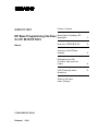
SIMATIC NET
Preface, Contents
DP Base Programming Interface
for CP 5613/CP 5614
Basic Steps in Creating a DP
Application
1
Overview of PROFIBUS DP
2
Overview of the DP Base
Interface
3
Description of the DP
Functions, Data, and Error
Codes
4
Manual
FAQ (Frequently Asked
Questions)
Where to Get Help,
Index, Glossary
C79000-G8976-C108-01
Release 1 1999
5
Safety Guidelines
This manual contains notices which you should observe to ensure your own personal safety, as well as to
protect the product and connected equipment. These notices are highlighted in the manual by a warning
triangle and are marked as follows according to the level of danger:
!
Danger
!
Warning
!
Caution
indicates that death, severe personal injury or substantial property damage will result if proper precautions
are not taken.
indicates that death, severe personal injury or substantial property damage can result if proper precautions
are not taken.
indicates that minor personal injury or property damage can result if proper precautions are not taken.
Note
draws your attention to particularly important information on the product, handling the product, or to a
particular part of the documentation.
Qualified Personnel
Only qualified personnel should be allowed to install and work on this equipment . Qualified persons are
defined as persons who are authorized to commission, to ground, and to tag circuits, equipment, and
systems in accordance with established safety practices and standards.
Correct Usage
Note the following:
!
Warning
This device and its components may only be used for the applications described in the catalog or the
technical description, and only in connection with devices or components from other manufacturers which
have been approved or recommended by Siemens.
This product can only function correctly and safely if it is transported, stored, set up, and installed correctly,
and operated and maintained as recommended.
Trademarks
SIMATIC ® and SIMATIC NET® are registered trademarks of Siemens AG.
Third parties using for their own purposes any other names in this document which refer to trademarks
might infringe upon the rights of the trademark owners.
Copyright Siemens AG, 1999, All rights reserved
The reproduction, transmission or use of this document or its
contents is not permitted without express written authority.
Offenders will be liable for damages. All rights, including rights
created by patent grant or registration of a utility or design, are
reserved.
Disclaimer
We have checked the contents of this manual for agreement with
the hardware and software described. Since deviations cannot be
precluded entirely, we cannot guarantee full agreement. However,
the data in this manual are reviewed regularly and any necessary
corrections included in subsequent editions. Suggestions for
improvement are welcome.
Siemens AG
Bereich Automatisierungs- und Antriebstechnik
Postfach 48 48, D-90327 Nürnberg
C79000-G8976-C108-01
© Siemens AG 1999
Technical data subject to change.
Siemens Aktiengesellschaft
Printed in the Federal Republic of Germany
Preface
Purpose of the Manual
This manual supports you when creating user programs for the DP programming
interface of the CP 5613/CP 5614.
It is assumed that you are familiar with writing user programs in the "C"
programming language in Windows NT.
Validity of the Manual
This manual applies to the following software versions:
x CP 5613/CP 5614 (DP Base V1.0)
x CP 5613/CP 5614 (DP Base V1.1)
Guide to the Manual
To help you to find specific information quickly, the manual includes the following
parts:
x At the front of the manual you will find a complete table of contents.
x At the back of the manual, you will find a comprehensive index with which you
can find topics quickly.
x After the index, there is also a glossary in which important terminology used in
the manual is defined.
DP Base Programming Interface for CP 5613/CP 5614
C79000-G8976-C108-01
3
Preface
4
DP Base Programming Interface for CP 5613/CP 5614
C79000-G8976-C108-01
Contents
1
Basic Steps in Creating a DP Application ......................................................................9
2
Overview of PROFIBUS DP ...........................................................................................13
3
2.1
Where Does PROFIBUS DP Fit In? .....................................................................14
2.2
The Master-Slave Concept of PROFIBUS DP......................................................16
2.3
Cyclic Polling by the Master.................................................................................18
2.4
Process Image of the DP Master .........................................................................19
2.5
Startup and Operational Phase of a DP System...................................................21
2.6
Modes of the DP Master ......................................................................................23
2.7
Separation of the Slave Data from the User Program...........................................25
2.8
Reliability of DP ...................................................................................................27
2.9
Control Frames to One or More Slaves................................................................28
2.10
Typical Sequences in DP.....................................................................................30
2.11
DP-V1 As an Extension of DP..............................................................................32
2.12
Slave Functionality of the CP 5614 ......................................................................34
Overview of the DP Base Interface ...............................................................................37
3.1
Functions and Data .............................................................................................38
3.2
The Importance of Configuration..........................................................................40
3.3
Consistent Access to the process image..............................................................42
3.4
Working with Hardware Events ............................................................................43
3.5
Fast Logic ...........................................................................................................44
3.6
Overview of Triggering and Receiving Events ......................................................45
3.7
3.7.1
3.7.2
3.7.3
3.7.4
3.7.5
Typical Sequences ..............................................................................................47
Initializing and Exiting the Master Mode ...............................................................47
Typical Sequences in Polling Master Operation ...................................................49
Typical Sequences for Polling DPC1 master operation.........................................51
Typical Sequences in Master Operation with Hardware Events ............................53
Typical Sequences in DPC1 Operation with Semaphores ....................................56
3.8
Properties of the CP 5614 (Slave Functions, Transfer Software) ..........................58
3.9
3.9.1
3.9.2
3.9.3
Typical Sequences for the CP 5614 Slave Module...............................................59
Initialization and Shutdown of the Slave Module in the "Simple" Mode .................59
Initialization and Shutdown of the Slave Module in the Dynamic" Mode................60
Typical Sequences with Semaphores on the slave Module ..................................62
3.10
Multiple Protocols, User Programs, CPUs............................................................64
DP Base Programming Interface for CP 5613/CP 5614
C79000-G8976-C108-01
5
Contents
4
6
Description of the DP Functions, Data, and Error Codes ............................................65
4.1
4.1.1
4.1.2
4.1.3
4.1.4
4.1.5
4.1.6
4.1.7
4.1.8
4.1.9
4.1.10
4.1.11
4.1.12
4.1.13
4.1.14
4.1.15
4.1.16
4.1.17
4.1.18
4.1.19
4.1.20
4.1.21
4.1.22
4.1.23
4.1.24
4.1.25
List of Functions of the CP 5613 and CP 5614.....................................................66
Overview of the Functions ...................................................................................68
DP_start_cp ........................................................................................................70
DP_reset_cp........................................................................................................71
DP_open .............................................................................................................72
DP_get_pointer ...................................................................................................73
DP_release_pointer.............................................................................................75
DP_close.............................................................................................................76
DP_get_err_txt ....................................................................................................78
DP_set_mode......................................................................................................79
DP_slv_state .......................................................................................................81
DP_read_slv_par.................................................................................................83
DP_global_ctrl .....................................................................................................85
DP_ds_read ........................................................................................................87
DP_ds_write........................................................................................................90
DP_read_alarm ...................................................................................................93
DP_alarm_ack.....................................................................................................96
DP_get_actual_cfg ..............................................................................................99
DP_enable_event..............................................................................................102
DP_disable_event .............................................................................................107
DP_get_result....................................................................................................108
DP_get_cref ......................................................................................................111
DP_init_sema_object.........................................................................................112
DP_delete_sema_object....................................................................................114
DP_fast_logic_on ..............................................................................................115
DP_fast_logic_off ..............................................................................................116
4.2
4.2.1
4.2.2
4.2.3
4.2.4
4.2.5
4.2.6
4.2.7
4.2.8
4.2.9
4.2.10
4.2.11
4.2.12
Additional Functions of the CP 5614 ..................................................................117
Overview of the Slave Module Functions ...........................................................118
DPS_open.........................................................................................................120
DPS_close ........................................................................................................124
DPS_start..........................................................................................................125
DPS_stop ..........................................................................................................126
DPS_get_baud_rate ..........................................................................................127
DPS_get_gc_command.....................................................................................129
DPS_get_state ..................................................................................................131
DPS_set_diag ...................................................................................................133
DPS_get_ind .....................................................................................................135
DPS_set_resp ...................................................................................................140
DPS_calc_io_data_len ......................................................................................142
4.3
4.3.1
4.3.2
4.3.3
4.3.4
4.3.5
4.3.6
4.3.7
4.3.8
4.3.9
4.3.10
4.3.11
4.3.12
Access to the Process Image of the CP 5613/CP 5614......................................143
Reading the Input Data of a DP Slave................................................................144
Reading the Diagnostic Data of a DP Slave .......................................................146
Writing the Output Data of a DP Slave ...............................................................148
Checking the Slaves for Changed Data .............................................................150
Querying the State of a DP Slave ......................................................................152
Querying Information about the DP Master ........................................................154
Querying Current Bus Parameters of the Master................................................155
Querying Information about DP Slaves ..............................................................158
Reading PROFIBUS Statistical Data..................................................................159
Querying the Fast Logic Status..........................................................................161
Activating/Deactivating the Generation of Hardware Events ...............................162
Sending Data with the CP 5614 as DP Slave.....................................................164
DP Base Programming Interface for CP 5613/CP 5614
C79000-G8976-C108-01
Contents
4.3.13 Receiving Data with the CP 5614 as DP Slave ..................................................165
4.3.14 Sending Diagnostic Data with the CP 5614 as DP Slave....................................166
5
6
4.4
4.4.1
Error Codes.......................................................................................................167
Entries in the error_decode, error_code_1 and error_code_2 Structure
Elements ...........................................................................................................171
4.5
Formats of the Slave Data .................................................................................175
4.6
4.6.1
4.6.2
4.6.3
4.6.4
4.6.5
4.6.6
Formats of the Slave Diagnostic Data ................................................................176
Overview of the Entire Structure ........................................................................177
Format of the Diagnostic Data Header ...............................................................178
Format of the Device-Related Diagnostic Data (Standard DP Slave)..................182
Format of the Device-Related Diagnostic Data (Slaves with DP-V1
Extensions) .......................................................................................................183
Format of ID-Related Diagnostics ......................................................................188
Format of Channel-Related Diagnostics.............................................................189
4.7
4.7.1
4.7.2
4.7.3
Format of the Slave Parameter Data..................................................................193
Structure of the General Slave Parameters........................................................194
Structure of the Parameter Assignment Data .....................................................197
Structure of the Configuration Data....................................................................202
FAQ (Frequently Asked Questions) ............................................................................205
5.1
FAQs about the Range of Functions of the Product ...........................................206
5.2
FAQs about Structuring the User Program.........................................................208
5.3
FAQ Check List for Programmers ......................................................................211
5.4
FAQs about Debugging and Starting Up Your Program......................................214
5.5
FAQs Miscellaneous Programming Questions ...................................................215
Where to Get Help........................................................................................................217
6.1
Help with Technical Questions...........................................................................218
6.2
Contacts for training with SIMATIC NET ............................................................221
7
Index.............................................................................................................................223
8
Glossary .......................................................................................................................227
DP Base Programming Interface for CP 5613/CP 5614
C79000-G8976-C108-01
7
Contents
8
DP Base Programming Interface for CP 5613/CP 5614
C79000-G8976-C108-01
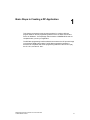
Basic Steps in Creating a DP Application
1
This chapter recommends a step-by-step procedure for creating a DP user
program based on the DP programming interface of the CP 5613 and CP 5614
known as "DP Base". The steps begin with the basics of PROFIBUS DP and are
completed when you test your application.
The DP Base programming interface allows direct access to the DP process image
in the dual-port RAM of the module. The DP Base programming interface is
therefore not compatible with the DP programming interface of the CP 5412 (A2),
the CP 5511, and the CP 5611.
DP Base Programming Interface for CP 5613/CP 5614
C79000-G8976-C108-01
9
Basic Steps in Creating a DP Application
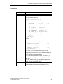
Procedure
The steps outlined below represent the fastest and simplest way of achieving your
aims:
Step
Description
1
Familiarize yourself with the basic principles of PROFIBUS DP. Read
the following chapter 2 (“Overview of PROFIBUS DP").
2
Familiarize yourself with the basic characteristics of the DP Base
programming interface of the CP 5613 and CP 5614. Read the
following chapter 3 (“Overview of the DP Base Interface").
3
Check through the contents of the subfolder "prog" in your installation
folder so that you know what it contains and the purpose of the
components for the subsequent steps.
The subfolder contains the following:
The "readme.txt" file with the latest additional information and most
recent modifications.
The C header file "dp_5613.h" with the functions and data structures
of the DP Base interface and "5613_ret.h" with the return codes.
The import libraries "dp_base.lib" and "dps_base.lib" for linking to
your user program.
The sample programs and corresponding databases in the
"examples" subfolder.
4
Now work through the source text of the sample program "ExamEasy"
and read through the functions and data accesses in Chapter 4
Description of the DP Functions, Data, and Error Codes
5
Adapt the "ExamEasy" sample program to suit your system
configuration by, for example, using additional or different slaves.
Compile and link the sample program and try it out. You may need to
extend the "ExamEasy" sample database (with COM PROFIBUS).
6
Now work through the source text of the sample program "ExamComp",
modify the program and try it out with an extended sample database.
7
If you want to use the slave functions of the CP 5614, you should also
work through the "transfer" sample, modify it to your requirements and
try it out with an extended sample database.
8
Please read the FAQs in Chapter 5, particularly the check list for
programmers and the information on structuring your user program.
Table continued on next page
10
DP Base Programming Interface for CP 5613/CP 5614
C79000-G8976-C108-01
Basic Steps in Creating a DP Application
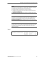
Table continued from previous page
Step
Description
9
Now create your own DP user program. You can use the "ExamComp"
sample as a basis.
10
Test your application. Refer to the information and tips in the FAQ list in
Chapter 5 and the diagnostic tools described in the installation
instructions.
DP Base Programming Interface for CP 5613/CP 5614
C79000-G8976-C108-01
11
Basic Steps in Creating a DP Application
12
DP Base Programming Interface for CP 5613/CP 5614
C79000-G8976-C108-01
Overview of PROFIBUS DP
2
This chapter will familiarize you with the basic principles of PROFIBUS DP.
DP Base Programming Interface for CP 5613/CP 5614
C79000-G8976-C108-01
13
Overview of PROFIBUS DP
2.1
Where Does PROFIBUS DP Fit In?
PROFIBUS - The Worldwide Fieldbus Strategy
The trend towards reducing costs in automation engineering has meant that
programmable controllers (PLCs), PCs, drives, transducers and sensors are being
networked more and more. This has resulted in greater distribution of these field
devices using a fieldbus as the common communications medium for exchanging
information.
The demand for an open, heterogeneous fieldbus system representing a safe and
long-term investment for the user has been met by PROFIBUS. PROFIBUS is a
bus system for communication between programmable controllers or PCs and field
devices based on the European standard EN 50 170, Volume 2. This means that
both users and manufacturers can be certain about long-term investments and
guarantees "openness" for all applications conforming with the standard worldwide.
With more than 2 million network nodes in over 200,000 applications, PROFIBUS
is the most successful open fieldbus having proved itself in applications in
production automation, process automation, drive engineering, and building
automation.
The PROFIBUS users organization represents a widespread information forum for
PROFIBUS manufacturers and users. This is an organization involving more than
800 users, manufacturers and advisers from more than 20 countries worldwide. As
a result of this cooperation, more than 1600 products are now available for use in
PROFIBUS systems.
Siemens has supported PROFIBUS for many years as an optimized fieldbus
solution and reliable investment for the user and supplies both products and
complete systems. Apart from the programmable controllers (PLCs), devices such
as network components, PC communications processors, and field devices for
PROFIBUS are also included in the wide range of products.
The Role of the PC in PROFIBUS
Apart from the trend towards distribution, the standard PC is also becoming more
important as an automation tool particularly in control tasks and for plant
visualization thanks to its increased performance and widespread availability.
14
DP Base Programming Interface for CP 5613/CP 5614
C79000-G8976-C108-01
Overview of PROFIBUS DP
The Advantages of DP
PROFIBUS DP is intended for fast data exchange in the fieldbus area.
Distributed peripheral devices collect the input signals locally and transfer them via
the fieldbus to the central controller in the PG/PC. In the opposite direction, the
central controller sends the output data to the distributed peripheral devices.
The use of PROFIBUS DP means a considerable reduction in cabling compared to
previous direct wiring of components.
DP Base Programming Interface for CP 5613/CP 5614
C79000-G8976-C108-01
15
Overview of PROFIBUS DP
2.2
The Master-Slave Concept of PROFIBUS DP
Distributed I/Os
The distributed peripheral I/Os (abbreviated to DP in the remainder of this manual)
allow a large number of analog and digital input/output modules to be used in a
distributed structure in the immediate vicinity of the process.
Node Classes
PROFIBUS DP defines two classes of bus nodes. Slaves as peripheral devices are
passive nodes. Masters (class 1) are active nodes and control the slaves.
DP Master Class 1
Using the CP 5613 or CP 5614, the PC can adopt the role of DP master.
Depending on the application, this role can also be adopted by, for example, a
SIMATIC S7 programmable logic controller. In the remainder of the manual, the DP
master class 1 is simply referred to as DP master.
DP Master Class 2
When installing and configuring the DP system or controlling the plant during
operation, you can also use master class 2 devices.
16
DP Base Programming Interface for CP 5613/CP 5614
C79000-G8976-C108-01
Overview of PROFIBUS DP
DP Slave
A DP slave is a peripheral device from which the master reads in input information
and to which it sends output information. There are also devices that provide only
input or only output information.
Slaves are generally inexpensive since passive participation on the bus is simple to
implement.
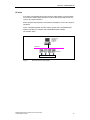
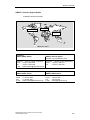
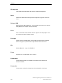
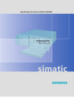
Figure 1 illustrates the basic structure and the components of a PROFIBUS DP
system controlled by a computer with a PROFIBUS master installed
(CP 5613/CP 5614).
DP master with
PROFIBUS
PC adapter
CP 5613
PROFIBUS
DP slaves
Process
Figure 1
Basic Structure of a DP System.
DP Base Programming Interface for CP 5613/CP 5614
C79000-G8976-C108-01
17
Overview of PROFIBUS DP
2.3
Cyclic Polling by the Master
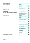
Polling
Communication between the DP master and the distributed nodes takes the form
of polling. Polling means that the DP master sends cyclic calls to its slaves during
the productive phase. A separate call frame is sent to each DP slave.
In one polling cycle, all the operational DP slaves are addressed. The next polling
cycle starts as soon as the last slave has been addressed. This ensures that the
data is up to date.
DP master
Output data
Input data
DP slaves
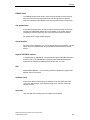
Figure 2
Schematic Representation of Polling
Output Data
The call frame contains the current output data that the DP slave will apply to its
output ports. The data belonging to this area are specified by the DP application. If
a DP slave does not have output ports, an "empty frame" is sent to it instead.
Input Data
The reception of a call frame must be confirmed by the DP slave by returning a
confirmation frame. The confirmation frame contains the current input data that are
applied to the input ports of the DP slave. If a DP slave does not have input ports,
an "empty frame" is returned instead.
18
DP Base Programming Interface for CP 5613/CP 5614
C79000-G8976-C108-01
Overview of PROFIBUS DP
2.4
Process Image of the DP Master
Automatic Updating of the Data
The CP 5613 or 5614 as the PROFIBUS DP master polls the data of the slaves
continuously and buffers this data on the PC. The DP application accesses this
data directly. This means that the DP application is not involved in polling the
slaves.
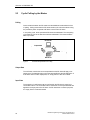
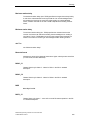
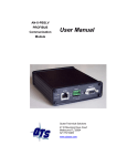
Figure 3 shows an overview of the data areas on the DP master.
DP Base Programming Interface for CP 5613/CP 5614
C79000-G8976-C108-01
19
Overview of PROFIBUS DP
Data Areas
There are three different data areas on the DP master for each configured DP
slave, as follows:
x Input data from the DP slave
x Output data to the DP slave
x Diagnostic data from the DP slave
The data are buffered by the CP 5613 or CP 5614 in memory that can be accessed
by the AP application directly without requiring function calls.
DP application
Input data
Output data
Diag. data
Slave data
Slave 1
Slave 2
Slave n
DP master
PROFIBUS
Figure 3
20
Data Areas of the DP Master
DP Base Programming Interface for CP 5613/CP 5614
C79000-G8976-C108-01
Overview of PROFIBUS DP
2.5
Startup and Operational Phase of a DP System
Functions of the DP Master during Startup and Operation
The DP master handles the following tasks:
x Initialization of the DP system
x Parameter assignment/configuration of the DP slaves
x Cyclic data transfer to the DP slaves
x Monitoring the DP slaves
x Storage of diagnostic information
Initialization
The DP master can only exchange productive data with the DP slaves when it has
assigned parameters to the slaves and configured them. The parameter
assignment/configuration takes place as follows:
x During the startup phase of the DP master
x Following any temporary failure of a DP slave during the productive phase
Parameter Assignment
The parameter assignment frame provides global operating parameters for the DP
slave (for example ID).
Configuration
The configuration frame is sent after the DP slave has been assigned parameters.
This frame contains the current configuration of the DP slave. The configuration
includes the number and type of input/output ports. The DP slave compares the
received configuration frame with the values that it determined itself during the
startup phase. If the values match, the DP slave confirms the configuration and
changes to the productive phase.
State of the Slave
During the operational phase, the DP master evaluates the confirmation frames
received from the DP slaves. Based on this information, the DP master can find out
the current state of the DP slaves.
DP Base Programming Interface for CP 5613/CP 5614
C79000-G8976-C108-01
21
Overview of PROFIBUS DP
Diagnostics
If a DP slave detects an error/fault during the initialization or productive phase, it
can signal this to the DP master in the form of diagnostic data. The received
diagnostic data are entered in the diagnostic area of the DP master. In this case,
the DP application is then responsible for reacting to the error.
22
DP Base Programming Interface for CP 5613/CP 5614
C79000-G8976-C108-01
Overview of PROFIBUS DP
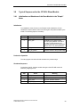
2.6
Modes of the DP Master
Overview
During communication with the DP slaves, the DP master can adopt the following
four modes:
x OFFLINE
x STOP
x CLEAR (or AUTOCLEAR)
x OPERATE
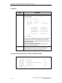
Modes
Each of these modes is characterized by defined actions between the DP master
and the DP slaves.
Master
Mode
Meaning
OFFLINE
No communication between the DP master and DP slaves.
This is the startup mode of the DP master.
STOP
In this mode, there is also no communication between the DP
master and the DP slaves. In contrast to the OFFLINE mode, a
DP diagnostic station (DP master class 2) can read out
diagnostic information from the DP master.
CLEAR
(or
AUTOCLEAR)
All the DP slaves entered and activated in the database are
assigned parameters and configured in this mode. This is
followed by the cyclic data exchange between the DP master
and DP slaves. In this CLEAR mode, the value 0 or empty
frames are sent to all slaves with a process output; in other
words, process output is deactivated. The input data of the
slaves are known and can be read out.
OPERATE
The cyclic, productive data transfer to the DP slaves takes
place in the OPERATE mode. This is the productive phase. In
this mode, the DP slaves are addressed one after the other by
the DP master. The call frame transfers the actual output data
and the corresponding response frame transfers the actual
input data.
DP Base Programming Interface for CP 5613/CP 5614
C79000-G8976-C108-01
23
Overview of PROFIBUS DP
Setting the Operating Mode
When the CP 5613 or CP 5614 is started up, the module runs through the modes
OFFLINE -> STOP -> CLEAR -> OPERATE controlled by the user program.
24
DP Base Programming Interface for CP 5613/CP 5614
C79000-G8976-C108-01
Overview of PROFIBUS DP
2.7
Separation of the Slave Data from the User Program
The process image is separate from the user program and the slaves.
To increase efficiency, the DP standard does not include flow control. The timing of
the cyclic updating of the process image of the DP master implementation is
connected neither to the DP slaves nor to the user program. Examples of different
situations are shown below:
Example: The slave writes too quickly
If, for example, an analog slave modifies its output data quickly (sequence 1.11,
1.2, 1.3, 1.42, 1.5, 1.6, 1.7, 1.8, ...), the DP master only receives a sequence of
"snapshots" that it enters in the process image (sequence 1.11, 1.3, 1.5, 1.8, ...).
Example: The user program reads too quickly
If the user program polls the process image extremely quickly, it obtains the values
more than once since it overtakes the polling cycle of the master. Based on the
example above, the user program then reads a sequence 1.1, 1.1, 1.1, 1.1, 1.3,
1.3, 1.3, 1.5, 1.5, 1.5, ...
Example: The user program writes too quickly
If the user program modifies the process image extremely quickly (sequence 1, 2,
3, 4, 5, 6, ...), it overtakes the polling cycle of the DP master. This then only
transfers "snapshots" to the slave (sequence 1, 4, 6, ...).
Example: The user program reads too slowly
If the user program only polls the process image occasionally, for example,
because it has various tasks to execute in the meantime, it is possible that some
values will be skipped. The sequence 1.1, 1.2, 1.3, 1.4 in the process image then
becomes, for example 1.1, 1.3 etc. in the user program.
DP Base Programming Interface for CP 5613/CP 5614
C79000-G8976-C108-01
25
Overview of PROFIBUS DP
Remedy
If the user program requires a better link to the slave than described above, there
are a number of options available:
x With the hardware events of the CP 5613 and CP 5614, the user program can
be informed of changes on the slave.
x With the DP protocol expansion DP-V1 master class 1 (DPC1), the user
program can read and write data with a confirmation and can confirm alarms (if
this is supported by the slaves).
x With user-specific implementations in the user program and on the slaves, userspecific flow controls can be achieved (packed into the DP process image or
DPC1 data) to link the master and slaves and to avoid loss of data.
x The hardware event at the start of the CP 5613/CP 5614 cycle can be used for
synchronization.
26
DP Base Programming Interface for CP 5613/CP 5614
C79000-G8976-C108-01
Overview of PROFIBUS DP
2.8
Reliability of DP
Reliability Concept
The DP programming interface provides various mechanisms to limit the effects of
the failure of a communication connection or the DP master.
x A watchdog function can be configured on the DP slave so that if a slave is not
accessed for a longer period of time it can change automatically to a safe state.
x The AUTOCLEAR function can be activated to ensure that if DP slaves are not
accessible, the master automatically changes to the CLEAR mode.
x A sign-of-life monitoring function can be activated on the DP master that
recognizes inactivity of a DP user program so that the DP slaves controlled by
the master can be changed to a safe state (for the software version in which this
function is available, refer to the version table in Section of the installation
instructions).
The AUTOCLEAR function
The AUTOCLEAR option can be set during configuration. If an error occurs on one
or more DP slaves during the productive phase, the DP master then changes
automatically to the AUTOCLEAR mode (the DP system is closed down). The
AUTOCLEAR mode is the same as the CLEAR mode. The DP master then sends
data with the value 0 or empty frames in the output direction to the DP slaves. The
DP master can no longer exit this mode automatically; in other words, the change
to the OPERATE mode must be triggered explicitly by the user.
DP Base Programming Interface for CP 5613/CP 5614
C79000-G8976-C108-01
27
Overview of PROFIBUS DP
2.9
Control Frames to One or More Slaves
Purpose of Control Frames
A control frame is a frame that the master sends to one slave, a group, several
groups or to all slaves. These frames are not acknowledged by the slaves.
Control frames are used to transfer control commands (known as global control
commands) to the selected slaves to allow synchronization. A control command
contains three components:
x Identifier indicating whether one or more DP slaves are being addressed
x Identification of the slave group
x Control command
Creating Groups
During configuration, you can assign a group identifier to a slave; in other words, it
is possible to include several slaves in one group.
Which slaves belong to a group is specified when you create the database. During
this phase, each DP slave can be assigned a group number. The DP slave is
informed of this group number during the parameter assignment phase. You can
specify a maximum of eight groups.
28
DP Base Programming Interface for CP 5613/CP 5614
C79000-G8976-C108-01
Overview of PROFIBUS DP
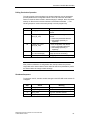
Control Commands
The following control commands can be sent to DP slaves when necessary during
operation:
Control
Commands
Description
FREEZE
The states of the inputs are read in and frozen. With this
function, your user program can achieve consistency over
several slaves when reading the input data; in other words,
it is certain that the values read were all set at the same
time.
UNFREEZE
The freezing of the inputs is canceled.
SYNC
Output is frozen. With this function, your user program can
achieve data consistency over several slaves when writing
output data; in other words, all the slaves use the new
values at the same time.
UNSYNC
The UNSYNC command cancels the SYNC command.
DP Base Programming Interface for CP 5613/CP 5614
C79000-G8976-C108-01
29
Overview of PROFIBUS DP
2.10
Typical Sequences in DP
Basic Sequence on the DP Master
A typical sequence run by a DP master when triggered by the user program is
shown below:
Step
Meaning
1
Initial situation: The DP master is in the OFFLINE mode.
2
The DP master changes to the STOP mode.
3
The DP master changes to the CLEAR mode. At this point it
automatically assigns parameters to the slaves and configures
them and then starts to send cyclic zero frames or empty frames
(depending on the configuration).
4
The DP master changes to the OPERATE mode.
5
The output data of the user program are now transferred
cyclically to the slaves, the input data are transferred from the
slaves to the user program.
6
The master changes to the intermediate modes CLEAR and
STOP and then changes to the final mode OFFLINE and is
turned off.
Failure of a Slave
While the DP master is in the CLEAR or OPERATE mode, a slave may fail; in other
words, no longer respond). The master then automatically attempts to reassign
parameters and reconfigure the slave so that it can be included in the cycle again.
Activating/Deactivating Slaves
When the DP master is in the CLEAR or OPERATE mode, slaves can be activated
or deactivated. A deactivated slave is no longer accessed by the master.
AUTOCLEAR
In some circumstances, the DP master can change from the OPERATE to the
AUTOCLEAR mode, see Section 2.8.
30
DP Base Programming Interface for CP 5613/CP 5614
C79000-G8976-C108-01
Overview of PROFIBUS DP
Receiving Diagnostic Data
When the slave returns high-priority input data to the master, it indicates that it has
diagnostic data. The master then fetches the information and makes it available to
the user program.
DP Base Programming Interface for CP 5613/CP 5614
C79000-G8976-C108-01
31
Overview of PROFIBUS DP
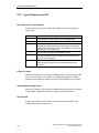
2.11
DP-V1 As an Extension of DP
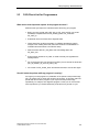
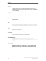
Overview of the DP Protocol with DP-V1 Extensions
Apart from cyclic DP master operation (see Section 2.3), two further extensions are
defined as DP-V1: DPC1 and DPC2. The paragraphs below contain an overview of
these extensions:
PG/PC
DP master class 1
PG/PC
DP master class 2
User program
User program
DP/DPC1 prog.
interface
DPC2 prog.
interface
DPC1
DPC2
DP
Cycl.
operation
MSCY C1
Acycl.
operation
MSAC_C1
Acycl. operation
MSAC_C2
DP slave with DP-V1
additional functions
DP-V1 Master Class 1 (DPC1)
With DPC1, a cyclic DP master can also send or read slave data and receive and
acknowledge alarms. These data are not process data but slave-specific additional
data (for example, new parameters). These data are not sent cyclically and must
be acknowledged explicitly by the slave.
32
DP Base Programming Interface for CP 5613/CP 5614
C79000-G8976-C108-01
Overview of PROFIBUS DP
DP-V1 Master Class 2 (DPC2)
An additional DP master that is not operating cyclically can establish connections
to slaves and send or read slave data using DPC2, for example, to reassign
parameters or for diagnostic purposes.
For the software version in which the DPC2 functions are available for the
CP 5613/CP 5614, refer to the version table in Section of the Installation
Instructions.
DP Base Programming Interface for CP 5613/CP 5614
C79000-G8976-C108-01
33
Overview of PROFIBUS DP
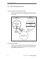
2.12
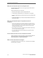
Slave Functionality of the CP 5614
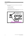
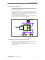
The Slave Functionality (Only CP 5614)
The piggy-back module on the CP 5614 provides slave functionality with its second
PROFIBUS port. The slave is controlled by another DP master.
Controlling
DP master
PC
PROFIBUS DP (I)
Slave
RS485
Master
application
Master
RS485
CP 5614
Slave
application
PROFIBUS DP (II)
DP slave
34
DP slave
DP Base Programming Interface for CP 5613/CP 5614
C79000-G8976-C108-01
Overview of PROFIBUS DP
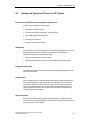
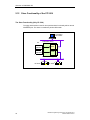
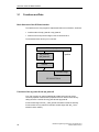
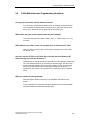
The Transfer Software (Only CP 5614)
To operate the CP 5614 with master and slave functionality, you can use the
sample transfer software. The transfer software transfers data between the master
and slave section of the CP 5614.
The transfer software includes an access with which additional input, output or
diagnostic jobs can be executed. Your user program can use this access to add
additional functions to the transfer program. (In the sample program, a counter on
the CP 5614 slave module is incremented.)
The example illustrates how a separate transfer function can access the process
image of the CP 5614 or CP 5613 with a local application.
Controlling
DP master
PROFIBUS DP (I)
Slave
RS485
Access
CP 5614
Master
RS485
PC
Transfer
software
PROFIBUS DP (II)
DP slave
DP slave
The Configuration for the Transfer Software (Only CP 5614)
To allow you to specify the separate transfer function, a configuration tool and a
configured transfer file are also shipped as an example.
Using the configuration tool, you can specify how data are copied from master to
slave and vice-versa.
DP Base Programming Interface for CP 5613/CP 5614
C79000-G8976-C108-01
35
Overview of PROFIBUS DP
36
DP Base Programming Interface for CP 5613/CP 5614
C79000-G8976-C108-01
Overview of the DP Base Interface
3
The programming interface of the CP 5613/CP 5614 is known as the DP Base
interface. This chapter explains the basic characteristics of the DP Base interface
including typical call and access sequences to prepare you for creating your own
DP applications.
For a detailed description of the function calls and data access, please refer to
Section 3.10.
DP Base Programming Interface for CP 5613/CP 5614
C79000-G8976-C108-01
37
Overview of the DP Base Interface
3.1
Functions and Data
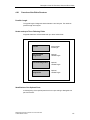
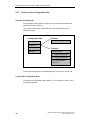
Basic Structure of the DP Base Interface
The interface to the user program is implemented with two mechanisms, as follows:
x Interface calls of the dp_base.dll or dps_base.dll
x Direct access to the process image on the CP 5613/CP 5614
The schematic below shows you an overview.
DP user program
C pointer
dp_base.dll
dps_base.dll
Drivers
Process image
CP 5613/CP 5614
Functions of the dp_base.dll and dps_base.dll
Your user program can execute administrative tasks and make use of less
commonly required communication properties of the CP 5613 and CP 5614 by
calling functions in the DP DLLs dp_base.dll and dps_base.dll.
Functions that begin with "DP_" have general and master module functionality.
Functions that are only relevant for the slave module begin with "dps_" (the s
stands for slave module).
38
DP Base Programming Interface for CP 5613/CP 5614
C79000-G8976-C108-01
Overview of the DP Base Interface
Direct Access to the Process Image
While your user program is running, regularly required data from the CP 5613 and
CP 5614 are available directly in a memory area of the CP. These include mainly
the input, output, and diagnostic data of the DP slaves but also include mode and
configuration data. Your user program can access the process image directly using
a C pointer.
DP Base Programming Interface for CP 5613/CP 5614
C79000-G8976-C108-01
39
Overview of the DP Base Interface
3.2
The Importance of Configuration
Using the DP Database
The DP database contains information about the bus parameters of PROFIBUS
and about the slaves on the network. This information is evaluated when the
CP 5613/CP 5614 starts up. This means that your user program does not need to
contain these details and does not need to be modified (for example, if the data
transmission rate is changed).
Configuring Slave Data Areas
During configuration, you specify the number and type (input, output, analog,
digital) of the data areas of all the slaves. This configuration data is sent to the
slave during startup and is then checked by the slave. If the configuration data
does not match the actual properties of the slave, the slave enters this in the
diagnostic data and it is not included in cyclic operation.
Activating the Watchdog
If the watchdog of a DP slave is activated in the configuration, the DP master must
communicate with the DP slave within a selected time.
If there is no communication within this time, the slave switches its outputs to a
safe state and no longer takes part in data transfer with the master section since
the slave assumes that a serious problem has occurred, for example wire break or
failure of the DP master.
The master must then assign parameters to the slave and configure it again.
Following this, the exchange of productive data can be resumed.
The values adopted by the outputs can be found in the descriptions of the DP
slaves.
Configuring the AUTOCLEAR Property
If one of the activated slaves does not take part in the data transfer and if the
AUTOCLEAR function is set, the DP master automatically changes to the CLEAR
mode (with the coding AUTOCLEAR).
40
DP Base Programming Interface for CP 5613/CP 5614
C79000-G8976-C108-01
Overview of the DP Base Interface
Configuring the "Min_Slave_Interval"
The "Min_Slave_Interval" time is the minimum time that must elapse after the
master accesses a slave before it can access it again. This is calculated
automatically based on the GSD data of the slaves.
DP Base Programming Interface for CP 5613/CP 5614
C79000-G8976-C108-01
41
Overview of the DP Base Interface
3.3
Consistent Access to the process image
Conflicts Accessing the Process Image
If, for example, your user program is currently reading the data of the DP slave
from the process image and at exactly the same time the DP master overwrites this
data with new data, your program could read the first few bytes from the previous
DP cycle and the remaining bytes from the current cycle. The data would then be
corrupted and inconsistent.
The Read Consistency Option
On the CP 5613 and CP 5614, you can decide whether or not you want to read the
data of the process image of the input data or diagnostic data consistently. In some
situations, for example, when the data is only 2 bytes long, you do not need to
select consistency since inconsistency can only occur when the data is longer.
Consistency can be guaranteed up to a maximum data length of 244 bytes.
Writing Data is always Consistent
On the CP 5613 and CP 5614, output data are always written consistently due to
the transfer mechanism on the CP 5613/CP 5614 up to the maximum data length
of 244 bytes.
42
DP Base Programming Interface for CP 5613/CP 5614
C79000-G8976-C108-01
Overview of the DP Base Interface
3.4
Working with Hardware Events
Reducing Load on the PC CPU
To relieve the PC of the computing time required for permanent polling on the DP
interface, you can use hardware events. Your user program then decides which
events will be reported by the CP 5613/CP 5614.
Possible Hardware Events
Hardware events can be triggered by the following criteria:
x The input data of a DP slave have changed. The hardware event can be
activated separately for each slave.
x A DP slave sends diagnostic data (regardless of whether it has changed or not).
The hardware event can be activated separately for each slave.
x Fast logic (see Section 3.5)
x A new DP cycle begins.
How Hardware Events are Activated
The process image memory area of the CP 5613 and CP 5614 contains a control
area for activating hardware events (activating fast logic is described in Section
3.5). Your user program can set and delete hardware events by simply writing to
this memory.
How Hardware Events are Transferred
A hardware event is transferred by incrementing a semaphore. This means that
your user program or one of its threads can wait for individual events; see also
Section 3.6.
Note
The use of hardware events for a lot of active slaves at the same time may result in
greater load on the PC than polling; refer to the suggestions in the FAQ list.
DP Base Programming Interface for CP 5613/CP 5614
C79000-G8976-C108-01
43
Overview of the DP Base Interface
3.5
Fast Logic
Purpose
With the fast logic property of the CP 5613/CP 5614, you can assign parameters to
the CP so that it automatically monitors data from slaves and triggers reactions on
other slaves.
This has the following advantages:
x The user program has less to do.
x The data transfer is faster due to separating the functions from the PC software.
x By being independent of the PC software, the reaction to the input signal is
guaranteed.
For the software version in which this property is available, refer to the version
table in Section in the Installation Instructions.
Procedure
Your program can activate functions that assign parameters for fast logic
(DP_fast_logic_on) or clear parameters again (DP_fast_logic_off).
44
DP Base Programming Interface for CP 5613/CP 5614
C79000-G8976-C108-01
Overview of the DP Base Interface
3.6
Overview of Triggering and Receiving Events
Properties of Hardware Events
The CP 5613/CP 5614 supports hardware events (see Section 3.4) with hardware
mechanisms of the CP so that these can be processed extremely quickly.
Hardware events (with the exception of fast logic) are activated in the process
image of the CP, signaled by semaphores and the details of the event are located
in the process image.
Properties of Software Events
Software events, on the other hand, are triggered by function calls, can be signaled
by semaphores and are fetched again by function calls.
DP Base Programming Interface for CP 5613/CP 5614
C79000-G8976-C108-01
45
Overview of the DP Base Interface
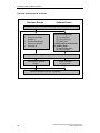
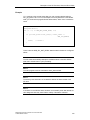
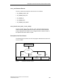
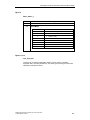
Overview of the Sequence of Events
Hardware Events
Software Events
Initialize required semaphore (during program startup)
Activate hardware event
x Event on input data
change *)
x Event on diagnostics
x Event on cycle start
x Fast logic on
Send aknowledged call
x DP_ds_read/write
x DP_get_actual_cfg
x DP_alarm_ack
or notify ready to receive with
DP_enable_event:
x for alarms/diagnostics
x for status changes
Wait at semaphore (optional for software events)
Fetch event in process
image
Fetch event with
DP_get_result
Release semaphore (at end of program)
*) Also possible if data changes in the slave module of the CP 5614.
46
DP Base Programming Interface for CP 5613/CP 5614
C79000-G8976-C108-01
Overview of the DP Base Interface
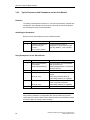
3.7
Typical Sequences
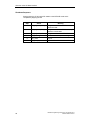
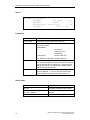
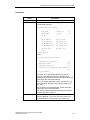
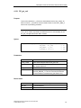
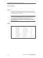
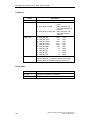
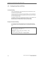
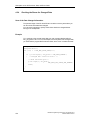
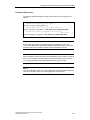
3.7.1
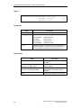
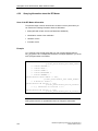
Initializing and Exiting the Master Mode
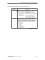
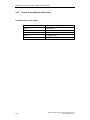
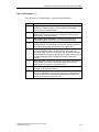
Initialization
The typical initialization of a CP 5613 or CP 5614 activates the CP and brings the
DP master to the OPERATE mode. The following steps are necessary:
Step
Action
Meaning
1
DP_start_cp
CP is initialized.
2
DP_open
Logon at the CP.
3
DP_get_pointer
Exclusive access to the process image.
4
DP_set_mode(Stop)
Change the master to the STOP mode.
5
DP_set_mode(Clear)
Change the master to the CLEAR mode,
slaves are included in cyclic operation
according to the information in the
database.
6
DP_set_mode(Operate)
Bring the master to the OPERATE
mode.
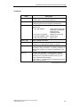
Productive Operation
The user program can access the data in the process image, trigger DP-V1 jobs
and fetch their confirmations as well as trigger other DP functions. The sequences
are described in greater detail on the following pages.
DP Base Programming Interface for CP 5613/CP 5614
C79000-G8976-C108-01
47
Overview of the DP Base Interface
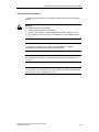
Shutdown Sequence
Shutting down the CP brings the DP master to the OFFLINE mode and is
completed by stopping the CP:
Step
48
Action
Meaning
1
DP_set_mode(Clear)
Bring the master to the CLEAR mode, the
slaves are reset.
2
DP_set_mode(Stop)
Bring the master to the STOP mode, cyclic
operation is terminated.
3
DP_set_mode(Offline)
Bring the master to the OFFLINE mode.
4
DP_release_pointer
Enable access to the process image.
5
DP_close
Log off.
6
DP_reset_cp
Stop the CP.
DP Base Programming Interface for CP 5613/CP 5614
C79000-G8976-C108-01
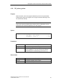
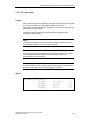
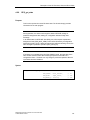
Overview of the DP Base Interface
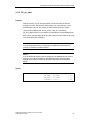
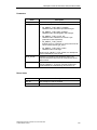
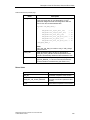
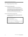
3.7.2
Typical Sequences in Polling Master Operation
Definition
After the CP has been initialized as described above, the user program can use the
CP for polling; in other words, for permanent direct access without waiting
mechanisms.
A cycle for reading and writing the process data can be implemented with the tools
described below.
DP Base Programming Interface for CP 5613/CP 5614
C79000-G8976-C108-01
49
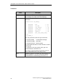
Overview of the DP Base Interface
Elements of a Polling Cycle
All the steps described below are achieved by direct access to the process image
using the C pointer as the result of the "DP_get_pointer" call.
Taken together, they represent an example of a polling cycle.
Step
50
Action
Meaning
1
Check the mode of the
master in the process
image (USIF_state,
Section 4.3.6)
Input data are only valid in the
OPERATE and CLEAR modes. Output
data can only be sent in the OPERATE
mode.
2
Check the state of the
slaves in the process
image (slave_state,
Section 4.3.5)
Communication functions only when
the slaves are in the READY mode.
3
Optional: Check whether a Your user program can recognize
slave has changed data
whether or not input data from a slave
(req_mask, Section 4.3.4), has changed.
If yes: reset req_mask
4
Read input data of the
slaves (slave_in[ ].data,
Section 4.3.1),
consistency by accessing
D_lock_in_slave_adr
For further processing in the user
program
5
Check new diagnostic
data of the slaves
(diag_count, Section
4.3.2)
If the diagnostic counter has changed
since the last cycle, there is new
diagnostic data.
6
If applicable, read
diagnostic data of the
slaves (slave_diag[ ].data,
Section 4.3.2),
consistency by accessing
D_lock_diag_slave_adr
For further processing in the user
program
7
Write output data of the
slaves (slave_out[ ].data)
As the result of processing the input
and diagnostic data
DP Base Programming Interface for CP 5613/CP 5614
C79000-G8976-C108-01
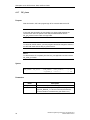
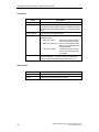
Overview of the DP Base Interface
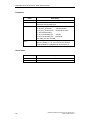
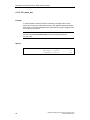
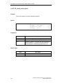
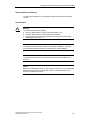
3.7.3
Typical Sequences for Polling DPC1 master operation
Definition
After initializing the CP as described above, the user program can use DPC1
functions during cyclic operation to exchange data with slaves and to respond to
alarms.
This section describes how these services are used in the polling mode; in other
words, when continuously querying slaves without waiting mechanisms.
Individual pairs of jobs and confirmations can be used parallel to each other.
Polling to Write to a Slave with DPC1
Step
Action
Meaning
1
Send the write job
(DP_ds_write)
On completion of the function, the job
is active.
2
Poll the result
(DP_get_result) until the
job is completed
The result can be recognized by the
order_id in the request field.
Polling to Read from a Slave with DPC1
Step
Action
Meaning
1
Send read job
(DP_ds_read)
On completion of the function, the job
is active.
2
Poll result with data
(DP_get_result) until the
job is completed.
The result can be recognized by the
order_id in the request field.
DP Base Programming Interface for CP 5613/CP 5614
C79000-G8976-C108-01
51
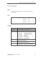
Overview of the DP Base Interface
Receiving and Responding to a DPC1 Alarm
Step
52
Action
Meaning
1
Attempt to receive alarm
(DP_read_alarm)
If there is no alarm, this is indicated by
the function result.
2
If received: Send alarm
acknowledgment
(DP_alarm_ack)
On completion of the function, the job
is active.
3
Poll final result
(DP_get_result) until the
job is completed
The result can be recognized by the
order_id in the request field.
DP Base Programming Interface for CP 5613/CP 5614
C79000-G8976-C108-01
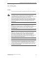
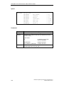
Overview of the DP Base Interface
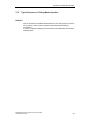
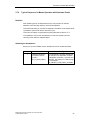
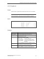
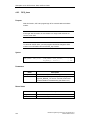
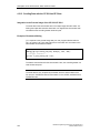
3.7.4
Typical Sequences in Master Operation with Hardware Events
Definition
After initializing the CP as described above, the user program can activate
hardware events and wait until they arrive with semaphores.
This means that polling for new data or diagnostic information can be omitted and it
is possible to synchronize with the start of the cycle.
This mode can replace or supplement the polling described in Section 3.7.2.
The initialization of this mode, the elements of continuous operation and the
canceling of the mode are explained below.
Initializing the Semaphores
Before you can use hardware events, semaphores must be created as follows:
Step
1
Action
Initialize a semaphore
for hardware events
(function
DP_init_sema_object)
DP Base Programming Interface for CP 5613/CP 5614
C79000-G8976-C108-01
Meaning
The DP Base DLL provides semaphores
for changes in the input data, reception
of diagnostic information, cycle start and
fast logic. The selector for a data change
is, for example,
DP_OBJECT_TYPE_INPUT_CHANGE.
53
Overview of the DP Base Interface
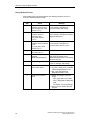
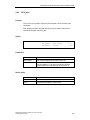
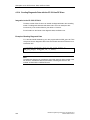
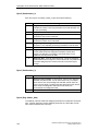
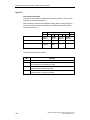
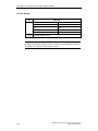
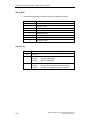
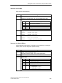
Using Hardware Events
After initializing the required semaphores, the following sequence can be run
through to activate and fetch events:
54
Step
Action
Meaning
1
Optional: Activate
hardware event for input
data changes (req_mask,
Section 4.3.11)
With this, the user program indicates
that it requires a semaphore to
increment if input data change.
2
Optional: Activate
hardware event for
diagnostic data
(req_mask, Section
4.3.11)
With this, the user program indicates
that it requires a semaphore to switch if
diagnostic data arrive.
3
Optional: Activate
hardware event for start of
cycle
(D_cycle_start_mask,
Section 4.3.11)
With this, the user program indicates
that it requires a semaphore to
increment at the start of a cycle.
4
Optional:
DP_fast_logic_on
Send fast logic job
5
Wait for semaphore (for
example
WaitForMultipleObjects)
The user program or the thread waits
until one of the events occurs.
"WaitForMultipleObjects" is a Windows
32-bit API function.
6
Detect the type of event
The semaphore identifies the type of
event, for example, data change.
7
Detect the source of the
event (which slave)
Check the flags in the process image:
req_mask = DPR_DATA_CHANGE
if data changes (Section 4.3.4)
diag_count changed during
diagnostics (Section 4.3.2)
8
Read and process the
event
Read by accessing the process
image:
— slave_in[n].data for input data
— slave_diag[n].data for diagnostic
data
— see Section 4.3.10 for fast logic
Pass on to other parts of the user
program.
DP Base Programming Interface for CP 5613/CP 5614
C79000-G8976-C108-01
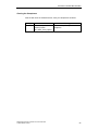
Overview of the DP Base Interface
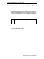
Clearing the Semaphores
After the last use of the hardware events, clear your semaphores as follows:
Step
Action
1
Clear semaphores for
events (function
DP_delete_sema_object)
DP Base Programming Interface for CP 5613/CP 5614
C79000-G8976-C108-01
Meaning
Releases the previously initialized
semaphore.
55
Overview of the DP Base Interface
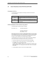
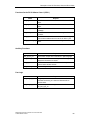
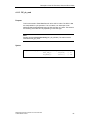
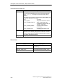
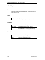
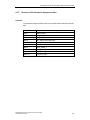
3.7.5
Typical Sequences in DPC1 Operation with Semaphores
Definition
The polling mode for DPC1 described in Section 3.7.3 can also be replaced by
operation with semaphores.
The initialization of this mode, the elements of continuous operation and canceling
the mode are described below.
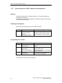
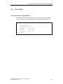
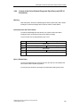
Initializing the Semaphores
Before it is used, the semaphore must be created as follows:
Step
1
Action
Initialize a semaphore for
asynchronous jobs
(function
DP_init_sema_object)
Meaning
The DP Base DLL provides a
semaphore for all asynchronous jobs
(type DP_OBJECT_TYPE_ASYNC).
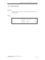
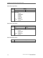
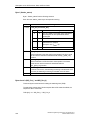
Using Semaphores for DPC1
Step
Action
Meaning
1
Send the write job
(DP_ds_write)
On completion of the function, the job
is active.
2
Wait for the semaphore
(for example,
WaitForMultipleObjects)
The user program or the thread waits
until the event occurs.
"WaitForMultipleObjects" is a Windows
32-bit API function.
3
Fetch result
(DP_get_result)
The result can be recognized by the
order_id in the request field.
The other DPC1 services function analogously.
56
DP Base Programming Interface for CP 5613/CP 5614
C79000-G8976-C108-01
Overview of the DP Base Interface
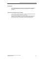
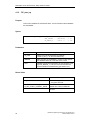
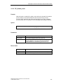
Clearing a Semaphore
After the last use, clear your semaphore as follows:
Step
Action
1
Clear semaphores for
events (function
DP_delete_sema_object)
DP Base Programming Interface for CP 5613/CP 5614
C79000-G8976-C108-01
Meaning
Releases the previously initialized
semaphore.
57
Overview of the DP Base Interface
3.8
Properties of the CP 5614 (Slave Functions, Transfer
Software)
Interaction Between the Master and Slave Functions
The DP master and slave on the CP 5614 can be operated together or singly.
"Simple Slave" Mode
In this mode, all the data necessary to include the slave module in the data
exchange are transferred to the CP when the DPS_open (...
slave_mode=DPS_SM_SIMPLE ...) function is called. The advantage of this is that
the user program can read outputs and write inputs simply without checking the
state of the slave module and without checking the parameters and configuration
data.
"Dynamic Slave" Mode
In this mode, the slave can set itself dynamically to the configuration of its master.
With the DPS_open() call, "DPS_SM_SIMPLE" is not selected. The user is
informed when parameter and configuration data are received. It then checks
whether it accepts the settings. This allows greater flexibility, particularly when the
slave has a modular structure. In this case, the view of the master can be
compared with the actual configuration of the slave.
Transfer Software
You are supplied with sample software with which the data can be routed between
various slaves of the master section and the slave module. This is particularly
advantageous in applications in which the master section is used to control a
separate bus and the PC is connected, for example, to a control computer via the
slave module.
58
DP Base Programming Interface for CP 5613/CP 5614
C79000-G8976-C108-01
Overview of the DP Base Interface
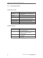
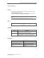
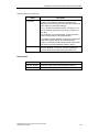
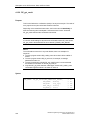
3.9
Typical Sequences for the CP 5614 Slave Module
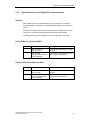
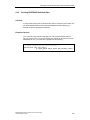
3.9.1
Initialization and Shutdown of the Slave Module in the "Simple"
Mode
Initialization
The initialization of the CP 5614 in the "Simple" mode activates the CP and
initializes the slave module so that it can be brought to the productive state by the
master. The following steps are necessary:
Step
Action
Meaning
1
DP_start_cp
CP is initialized.
2
DPS_open
Initialization of the slave module:
The "DPS_SM_SIMPLE" bit is set in
the "slave_mode" parameter, the
expected parameter and configuration
data are in the "init_data" parameter.
3
DPS_start
Start the slave module
4
DP_get_pointer
Exclusive access to the process image.
Productive Operation
The user program can read and write the data in the process image.
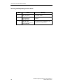
Shutdown Sequence
To shut down the CP, the slave module changes to the OFFLINE mode and
finishes by stopping the CP:
Step
Action
Meaning
1
DPS_stop
2
DP_release_pointer
Enable access to the process image.
3
DPS_close
Log off on the slave module
4
DP_reset_cp
Stop the CP.
DP Base Programming Interface for CP 5613/CP 5614
C79000-G8976-C108-01
Bring the slave to the OFFLINE state
59
Overview of the DP Base Interface
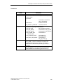
3.9.2
Initialization and Shutdown of the Slave Module in the Dynamic"
Mode
Initialization
Initializing the CP 5614 in the "Dynamic" mode activates the CP and initializes the
slave module so that it responds on the bus. The parameter and configuration
frames sent by the master must be checked and acknowledged by the user. The
following steps are necessary:
Step
60
Action
Meaning
1
DP_start_cp
The CP is initialized
2
DPS_open
Initialization of the slave module:
The "DPS_SM_SIMPLE" bit is not set
in the "slave_mode" parameter, the
"init_data" parameter contains the
default configuration.
3
DPS_start
Start the slave module
4
DP_get_pointer
Exclusive access to the process image.
DP Base Programming Interface for CP 5613/CP 5614
C79000-G8976-C108-01
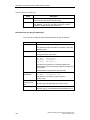
Overview of the DP Base Interface
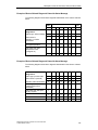
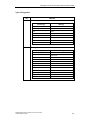
Polling Productive Operation
The user program can access data in the process image but must be prepared to
process parameter and configuration frames. This is the case when the master
wants to include the slave module in data exchange (for example, when the master
starts up or after the bus connector has been removed and reinserted, ...). The
following sequence must be executed cyclically in a main program loop.
Step
Action
Meaning
1
DPS_get_ind
Query whether indications have
arrived.
2a
If DPS_CHK_PRM:
DPS_set_resp
If a new parameter assignment has
arrived:
Check user parameter data and
Acknowledge positively or
negatively
2b
If DPS_CHK_CFG:
DPS_set_resp
If a new configuration has arrived:
Check configuration data and
Acknowledge positively or
negatively.
3
Access to PI
(PI - Process Image)
Read and write data in the process
image (access as necessary)
4
Go to Step 1.
DPS_get_ind must be called cyclically.
Note
After positive confirmation of configuration data, the input data in the process
image table of the slave module must be written at least once (initialization), before
the slave module can change to data exchange.
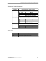
Shutdown Sequence
To shut down the CP, the slave module changes to the OFFLINE mode and the CP
is stopped:
Step
Action
Meaning
1
DPS_stop
Bring the slave to the OFFLINE state
2
DP_release_pointer
Enable access to the process image.
3
DPS_close
Log off on the slave module
4
DP_reset_cp
Stop the CP.
DP Base Programming Interface for CP 5613/CP 5614
C79000-G8976-C108-01
61
Overview of the DP Base Interface
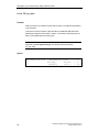
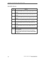
3.9.3
Typical Sequences with Semaphores on the slave Module
Definition
The polling mode described in Section 3.7.3 can also be replaced by operation with
semaphores. The initialization of this mode, the elements of continuous operation
and canceling the mode are described below.
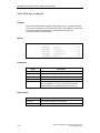
Initializing the Semaphore
Before it is used, the semaphore must be created as follows:
Step
1
Action
Initialize a semaphore for
asynchronous jobs
(function
DP_init_sema_object)
Meaning
The DP Base Lib provides a
semaphore for all asynchronous jobs
(type DP_OBJECT_TYPE_ASYNC).
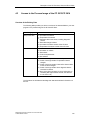
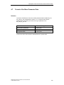
Using Semaphores for the Slave Module
Step
Action
Meaning
1
Wait for the semaphore
(for example,
WaitForMultipleObjects)
The user program or the thread waits
until an event occurs.
"WaitForMultipleObjects" is a Windows
32-bit API function.
2
DPS_get_ind
Fetch arrived indications
3a
If DPS_CHK_PRM:
If a new parameter assignment has
arrived:
DPS_set_resp
Check user parameter data and
acknowledge positively or negatively
If DPS_CHK_CFG:
If a new configuration has arrived:
DPS_set_resp
Check configuration data and
acknowledge positively or negatively
3b
4
Go to Step 1.
Note
After positive confirmation of configuration data, the input data in the process
image table of the slave module must be written at least once (initialization), before
the slave module can change to data exchange.
62
DP Base Programming Interface for CP 5613/CP 5614
C79000-G8976-C108-01
Overview of the DP Base Interface
Clearing the Semaphore
After the last use, clear your semaphore as follows:
Step
Action
1
Clear semaphores for
events (function
DP_delete_sema_object)
DP Base Programming Interface for CP 5613/CP 5614
C79000-G8976-C108-01
Meaning
Releases the previously initialized
semaphore.
63
Overview of the DP Base Interface
3.10
Multiple Protocols, User Programs, CPUs
Multiple CP Operation
For the software version in which the simultaneous operation of multiple
CP 5613/CP 5614 modules is supported, refer to the version table in Section of
the Installation Instructions.
Multiple Application Programs
For the software version in which the simultaneous operation of multiple application
programs is supported, refer to the version table in Section of the Installation
Instructions.
Multiple CPUs in one PC
Operation in PCs with multiple CPUs is supported
64
DP Base Programming Interface for CP 5613/CP 5614
C79000-G8976-C108-01
Description of the DP Functions, Data, and
Error Codes
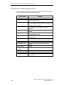
4
This chapter describes the individual functions and options for accessing data in
the process image of the CP 5613 and CP 5614.
The chapter also explains the significance of the possible error codes.
The data formats for I/O data and for diagnostics are also described.
The chapter is primarily intended as a source of reference when you are writing
your user programs.
DP Base Programming Interface for CP 5613/CP 5614
C79000-G8976-C108-01
65
Description of the DP Functions, Data, and Error Codes
4.1
List of Functions of the CP 5613 and CP 5614
Conventions in the Text
In the descriptions in this chapter, the following conventions are used in the
function declaration:
Notation
Meaning
// in
The value is provided by the user program as input for the
function.
// out
The value is returned to the user program by the function.
// inout
The value must be initialized and is updated on completion
of the function.
Uniform Call Structure of the Functions of dp_base.dll
The functions have a uniform structure, as follows:
Error class = DP_... (
Job-defining parameter 1,
...
Job-defining parameter n,
DP_ERROR_T *error);
Each function returns one of the error classes described below. If an error occurs,
then depending on the error class, the DP_ERROR_T structure contains detailed
error information (see Section 4.4). How the error is evaluated and the function
DP_get_err_txt are explained in the sample programs supplied.
In the descriptions of the functions, the return values are described in tables as
shown below based on the example of the DP_start_cp function call:
x If the return value is DP_OK, the function was executed successfully.
x If the return value is not DP_OK and the error_code component in the
DP_ERROR_T error structure has the value
CI_RET_START_ALREADY_DONE, the CP has already been started using a
different database. Your user program should be able to react to such explicit
error codes.
x In other situations, the error only occurs in exceptional cases.
66
DP Base Programming Interface for CP 5613/CP 5614
C79000-G8976-C108-01
Description of the DP Functions, Data, and Error Codes
Header Files
The C header files dp_5613.h and dps_5614.h with the detailed C description of
the functions and data structures is in the "prog" subfolder of your software
installation.
Synchronous and Asynchronous Functions
Unless explicitly indicated, the execution of a task is completed at the end of the
function (in other words, the function is synchronous).
Some functions (for example, DP_ds_read) only trigger execution and are then
completed. The actual result of the function must then be fetched with the
DP_get_result function (in other words, the functions are asynchronous).
DP Base Programming Interface for CP 5613/CP 5614
C79000-G8976-C108-01
67
Description of the DP Functions, Data, and Error Codes
4.1.1
Overview of the Functions
Administrative Functions
Name
Purpose
DP_start_cp
Downloads the firmware and the database to the
CP 5613/CP 5614.
DP_open
Logs on a DP user program, assigns a user handle.
DP_get_pointer
Requests a pointer to the process image.
DP_init_sema_object
This function initializes a semaphore at which your
user program can wait for the arrival of events.
DP_delete_sema_object
This function clears a semaphore again.
DP_release_pointer
Releases the pointer to the process image.
DP_close
The DP user logs off.
DP_reset_cp
Stops the CP firmware.
Standard DP Functions
Name
68
Purpose
DP_set_mode
This function sets the required DP mode (OFFLINE,
STOP, CLEAR, OPERATE).
DP_slv_state
This function activates or deactivates a slave
explicitly and can be used to change the
AUTOCLEAR property.
DP_read_slv_par
This function reads out the parameters of a DP slave
from the database.
DP_global_ctrl
This function sends a global control command to one
or more slaves.
DP Base Programming Interface for CP 5613/CP 5614
C79000-G8976-C108-01
Description of the DP Functions, Data, and Error Codes
Functions for the DP-V1 Master Class 1 (DPC1)
Name
Purpose
DP_ds_read
This function sends a "Read Data Record" call to a DP-V1
slave.
DP_ds_write
This function sends a "Write Data Record" call to a DP-V1
slave.
DP_read_alarm
This function fetches a DPC1 alarm or a DPC1 status
message.
DP_alarm_ack
This function sends an "Alarm Acknowledge" call to a DPV1 slave.
DP_get_cref
This function obtains the communication reference (c_ref)
from the slave address and the user ID for DP-V1 jobs.
DP_get_actual_cfg
This function reads out the current configuration data of a
slave.
Auxiliary Functions
Name
Purpose
DP_get_err_txt
This function outputs error information in plain language.
DP_enable_event
This function activates the waiting for status changes or
diagnostic information on slaves.
DP_get_result
This function fetches the confirmation of an asynchronous
call and other software events.
DP_disable_event
Cancels DP_enable_event
Fast Logic
Name
Purpose
DP_fast_logic_on
Assigns parameters to the CP 5613/CP 5614 for
automatic monitoring of a slave and data transfer to
another slave.
DP_fast_logic_off
Cancels the parameter assignment made with
DP_fast_logic_on.
DP Base Programming Interface for CP 5613/CP 5614
C79000-G8976-C108-01
69
Description of the DP Functions, Data, and Error Codes
4.1.2
DP_start_cp
Purpose
This function initializes the CP 5613/CP 5614. The CP firmware and the database
are downloaded.
Syntax
DPR_DWORD DP_start_cp
( DPR_STRING
DPR_STRING
DP_ERROR_T
*cp_name,
*database,
*error );
// in
// in
// out
Parameters
Name
Description
cp_name
Name of the CP 5613/CP 5614 (for example,
"CP5613_5614_1" for the first inserted CP).
database
Path and name of the database - if there is a zero pointer,
the database name set in the start menu is used.
error
Address of a structure provided by the user program of the
type DP_ERROR_T - If an error occurred, the structure
contains details for troubleshooting (see Section 4.4).
Return Value
Name
70
Description
DP_OK
Successful completion of the function
- The green LED is lit.
otherwise if error->error_code ==
CI_RET_START_ALREADY_ DONE
Error: The CP has already been
started with a different database.
other
Unsuccessful completion of the
function.
DP Base Programming Interface for CP 5613/CP 5614
C79000-G8976-C108-01
Description of the DP Functions, Data, and Error Codes
4.1.3
DP_reset_cp
Purpose
This function resets the CP 5613/CP 5614. Following this, the CP is no longer
active on the bus (Token LED is off).
If other applications are still using the CP, this function does not reset it, in this
case use the "Installation" diagnostic tool in the start menu.
Note
To use the CP again, your user program must use the DP_start_cp call.
Syntax
DPR_DWORD DP_reset_cp
(DPR_STRING
DP_ERROR_T
*cp_name,
*error );
// in
// out
Parameters
Name
Description
cp_name
Configured name of the CP 5613/CP 5614, for example,
"CP5613_5614_1" for the first inserted CP.
error
Address of a structure provided by the user program of the
type DP_ERROR_T - If an error occurred, the structure
contains details for troubleshooting (see Section 4.4).
Return Value
Name
Description
DP_OK
Successful completion of the function
otherwise if error->error_code ==
CI_RET_RESET_CP_USED
Unsuccessful because other
applications are still using the CP.
other
Unsuccessful completion of the
function
DP Base Programming Interface for CP 5613/CP 5614
C79000-G8976-C108-01
71
Description of the DP Functions, Data, and Error Codes
4.1.4
DP_open
Purpose
This function logs on a DP user program for communication. If successful, the
function returns a user handle. The user handle must be included in all further
function calls.
Syntax
DPR_DWORD
DP_open (
DPR_STRING
DPR_DWORD
DP_ERROR_T
*cp_name,
*user_handle,
*error );
// in
// out
// out
Parameters
Name
Description
cp_name
Configured name of the CP 5613/CP 5614, (for example,
"CP5613_5614_1" for the first inserted CP).
user_handle
Pointer to the user handle variable - if successful, the user
handle assigned to the user program is entered here.
error
Address of a structure provided by the user program of the
type DP_ERROR_T - If an error occurred, the structure
contains details for troubleshooting (see Section 4.4).
Return Value
Name
72
Description
DP_OK
Successful completion of the function.
otherwise if error->error_code ==
CI_RET_OPEN_CP_NOT_
STARTED
CP not started.
otherwise if error->error_code ==
DP_RET_TOO_MANY_USR
No further instances can log on at the
dp_base.dll.
other
Unsuccessful completion of the
function.
DP Base Programming Interface for CP 5613/CP 5614
C79000-G8976-C108-01
Description of the DP Functions, Data, and Error Codes
4.1.5
DP_get_pointer
Purpose
With this function, a DP user program obtains the exclusive pointer to the process
data of the CP 5613/CP 5614. Using this pointer, the DP user program can then
access the data image of the CP 5613/CP 5614.
General Notes
Note 1
Only one program can be in possession of a pointer to the process image at any
one time. This prevents conflicts accessing the registers for controlling consistency
in the process image (for example, refer toD_lock_in_slave_adr in Section 4.3.1).
Note 2
Note that access to the dual-port RAM without a valid pointer leads to an access
violation in Windows NT. The reason for this is as follows: The DP_get_pointer
was not called, the DP_get_pointer is terminated with an error message or the
pointer was released again with DP_release_pointer.
Note 3
This function requires a relatively long run-time and if it is called often, can be
detrimental to the real-time properties of your user program.
Note 4
The CP must already have been started with DP_start_cp.
DP Base Programming Interface for CP 5613/CP 5614
C79000-G8976-C108-01
73
Description of the DP Functions, Data, and Error Codes
Syntax
DPR_DWORD DP_get_pointer (
DPR_DWORD
DPR_DWORD
DPR_CP5613_DP_T
DP_ERROR_T
user_handle,
// in
timeout,
// in
volatile **dpr,
// out
*error); // out
Parameters
Name
Description
user_handle
User handle assigned with the DP_open call.
timeout
Duration of the maximum wait time (in milliseconds) until
the function returns.
Limit values:
0:
No wait time
(Function returns
immediately)
0x7FFFFFFE:
Maximum wait time
DP_TIMEOUT_FOREVER: "Endless" wait time
dpr
Address of a pointer provided by the user program. If
successful, the address for access to the process image of
the CP 5613/CP 5614 is entered here - using this pointer,
the DP user program can then access the data image of
the CP 5613/CP 5614 directly.
error
Address of a structure provided by the user program of the
type DP_ERROR_T - If an error occurred, the structure
contains details for troubleshooting (see Section 4.4).
Return Value
Name
74
Description
DP_OK
Successful completion of the function
otherwise if error->error_code ==
DP_RET_TIMEOUT
Timeout – Pointer being used by another
program.
other
Unsuccessful completion of the function
DP Base Programming Interface for CP 5613/CP 5614
C79000-G8976-C108-01
Description of the DP Functions, Data, and Error Codes
4.1.6
DP_release_pointer
Purpose
With this function, a DP user program releases the pointer to the process data.
Following this, the DP user program can no longer access the data image of the
CP 5613/CP 5614 directly.
Note
This function requires a relatively long run-time and if it is called often, can be
detrimental to the real-time properties of your user program.
Syntax
DPR_DWORD
DP_release_pointer(
DPR_DWORD
user_handle,
DP_ERROR_T *error );
// in
// out
Parameters
Name
Description
user_handle
User handle assigned with the DP_open call.
error
Address of a structure provided by the user program of the
type DP_ERROR_T. If an error occurred, the structure
contains details for troubleshooting (see Section 4.4).
Return Value
Name
Description
DP_OK
Successful completion of the function
other
Unsuccessful completion of the function
DP Base Programming Interface for CP 5613/CP 5614
C79000-G8976-C108-01
75
Description of the DP Functions, Data, and Error Codes
4.1.7
DP_close
Purpose
With this function, a DP user program logs off for communication at the CP.
Note 1
If the logoff was successful, the user handle is no longer valid and must not
continue to be used. The pointer to the dual-port RAM obtained with the
DP_get_pointer function is also no longer valid.
Note 2
To shut down the DP master, your user program should first change the master to
the OFFLINE mode with the DP_set_mode function.
Note 3
To disconnect the CP completely from the bus, your application can then use the
DP_reset_cp function.
Syntax
DPR_DWORD
DP_close
(DPR_DWORD
DP_ERROR_T
user_handle,
*error );
// in
// out
Parameters
Name
76
Description
user_handle
User handle assigned with the DP_open call.
error
Address of a structure provided by the user program of the
type DP_ERROR_T - If an error occurred, the structure
contains details for troubleshooting (see Section 4.4).
DP Base Programming Interface for CP 5613/CP 5614
C79000-G8976-C108-01
Description of the DP Functions, Data, and Error Codes
Return Value
Name
Description
DP_OK
Successful completion of the function
other
Unsuccessful completion of the function
DP Base Programming Interface for CP 5613/CP 5614
C79000-G8976-C108-01
77
Description of the DP Functions, Data, and Error Codes
4.1.8
DP_get_err_txt
Purpose
This function obtains detailed error information from the return values of the
DP_ERROR_T error structure in plain language.
Syntax
DPR_DWORD
DP_get_err_txt (
DP_ERROR_T
DPR_STRING
DPR_STRING
*error,
// in
*language,
// in
text[DP_ERR_TXT_SIZE] ); // out
Parameters
Name
Description
error
Address of a structure provided by the user program of the
type DP_ERROR_T. The structure contains the error values
of a previously called DP function (see Section 4.4).
language
Language of the error text to be displayed:
"German"
"English"
text
Pointer to the data area in which the error text including the
terminating zero byte is stored.
Return Value
Name
Description
DP_OK
Successful completion of the function
other
Unsuccessful completion of the function
Note
If a string other than "German" or "English" is entered in the "language" parameter,
the error text is displayed in English.
78
DP Base Programming Interface for CP 5613/CP 5614
C79000-G8976-C108-01
Description of the DP Functions, Data, and Error Codes
4.1.9
DP_set_mode
Purpose
This function sets the required DP mode (OFFLINE, STOP, CLEAR, OPERATE).
!
Warning
If you want the master to change from DP_CLEAR to DP_OPERATE, but
AUTOCLEAR (see 2.8) is configured and one or more slaves have failed, it cannot
change to the DP_OPERATE mode. Instead of this, it changes to
DP_AUTOCLEAR which has the identical significance to DP_CLEAR. Your user
program must therefore not query whether or not the DP_OPERATE mode has
been reached endlessly but must also check whether the master has changed to
the DP_AUTOCLEAR mode as a result of a slave problem (USIF_state, see
Section 4.3.6).
Note 1
Since it can take some time to reach a new mode (depending on the data
transmission rate, number of slaves etc.), the function does not wait until the new
mode has been reached. This prevents the user program being delayed
unnecessarily long.
Note 2
When a new mode is set, no other modes can be skipped. Starting from the
current mode, the modes must be run through in the specified (ascending or
descending) order OFFLINE - STOP - CLEAR - OPERATE. Following a
DP_set_mode call, the "Master Info" area of the process image (USIF_state, see
Section 4.3.6) must be queried to check whether or not the new mode was
reached. Only then can a new mode be set.
Note 3
If your DP master changed to the AUTOCLEAR mode instead of the OPERATE
mode, because a slave with the AUTOCLEAR property could not change to
productive operation, you can nevertheless change the DP master to OPERATE.
To do this, first deactivate the slave or its AUTOCLEAR property (in each case
using the DP_set_slv_state call).
DP Base Programming Interface for CP 5613/CP 5614
C79000-G8976-C108-01
79
Description of the DP Functions, Data, and Error Codes
Syntax
DPR_DWORD DP_set_mode (DPR_DWORD
DPR_WORD
DP_ERROR_T
user_handle,
mst_mode,
*error );
// in
// in
// out
Parameters
Name
Description
user_handle
User handle assigned with the DP_open call.
mst_mode
New mode to be set. The following constants can be used:
error
DP_OFFLINE:
OFFLINE mode
DP_STOP:
STOP mode
DP_CLEAR:
CLEAR mode
DP_OPERATE:
OPERATE mode
Address of a structure provided by the user program of the
type DP_ERROR_T. If an error occurred, the structure
contains details for troubleshooting (see Section 4.4).
Return Value
Name
80
Description
DP_OK
The change in the DP mode was
activated.
otherwise if error->error_code ==
DP_RET_CP_REQ_ACTIV
There is still a DP_set_mode request
being processed.
otherwise if error->error_code ==
DP_RET_CP_WRONG_MODE
The selected master mode is not
permitted (a master mode has been
skipped).
other
Unsuccessful completion of the function
DP Base Programming Interface for CP 5613/CP 5614
C79000-G8976-C108-01
Description of the DP Functions, Data, and Error Codes
4.1.10 DP_slv_state
Purpose
With this function, you can change the state of a DP slave while the DP user
program is running. The slave can either be taken out of processing or can be
activated again. You can also change the AUTOCLEAR property of a slave.
Using the slave address 0xFF and slv_mode == DP_SLV_ACTIVATE/
DP_SLV_DEACTIVATE you can activate or deactivate the AUTOCLEAR property.
As an option, selected single slaves (slv_add != 0xFF) can be included or removed
from the AUTOCLEAR processing.
Note 1
If the AUTOCLEAR property is configured in the database, the AUTOCLEAR
property of all slaves is already activated.
Note 2
If the AUTOCLEAR property was not configured in the database and you want to
activate it you must first activate the AUTOCLEAR property generally (slave
address 0xFF) and then activate the AUTOCLEAR property of the individual
slaves.
Syntax
DPR_DWORD
DP_slv_state(DPR_DWORD
DPR_WORD
DPR_WORD
DP_ERROR_T
DP Base Programming Interface for CP 5613/CP 5614
C79000-G8976-C108-01
user_handle,
slv_add;
slv_mode,
*error );
//
//
//
//
in
in
in
out
81
Description of the DP Functions, Data, and Error Codes
Parameters
Name
Description
user_handle
User handle assigned with the DP_open call.
slv_add
Address of the slave or 0xFF with the meaning: Activate or
deactivate AUTOCLEAR for all.
slv_mode
Required slave state:
DP_SLV_ACTIVATE
DP_SLV_DEACTIVATE
AUTOCLEAR setting:
DP_AUTOCLEAR_ON
DP_AUTOCLEAR_OFF
Activate the slave
Deactivate the slave
Activate
Deactivate
The values can also be ORed.
Address of a structure provided by the user program of the
type DP_ERROR_T. If an error occurred, the structure
contains details for troubleshooting (see Section 4.4).
error
Return Value
Name
82
Description
DP_OK
Successful completion of the function
other
Unsuccessful completion of the function
DP Base Programming Interface for CP 5613/CP 5614
C79000-G8976-C108-01
Description of the DP Functions, Data, and Error Codes
4.1.11 DP_read_slv_par
Purpose
This function queries the parameters of a currently active DP slave of the
CP 5613/CP 5614.
Syntax
DPR_DWORD
DP_read_slv_par
(DPR_DWORD
DPR_WORD
DPR_WORD
DPR_WORD
DPR_BYTE
DP_ERROR_T
user_handle,//
slv_add,
//
type,
//
*data_len; //
*data;
//
*error );
//
in
in
in
out
out
out
Parameters
Name
Description
user_handle
User handle assigned with the DP_open call.
slv_add
Address of the slave
type
Required data type (see Section 4.7):
DP_SLV_TYP:
General slave parameters
DP_SLV_PRM:
Parameter assignment data
DP_SLV_CFG:
Configuration
DP_SLV_ADD_TAB: Add tab data
DP_SLV_USR:
User-specific data
With the last two, no data are supplied.
data_len
Address of a length variable - the number of valid bytes in
the data buffer is entered here.
data
Pointer to a data area - the data area must be at least
DP_PAR_SIZE long (see Section 4.7).
error
Address of a structure provided by the user program of the
type DP_ERROR_T - If an error occurred, the structure
contains details for troubleshooting (see Section 4.4).
DP Base Programming Interface for CP 5613/CP 5614
C79000-G8976-C108-01
83
Description of the DP Functions, Data, and Error Codes
Return Value
Name
84
Description
DP_OK
Successful completion of the function
otherwise if error->error_code ==
DP_RET_CP_ADR_NOT_IN_DB
Error: The specified slave does not exist.
other
Unsuccessful completion of the function
DP Base Programming Interface for CP 5613/CP 5614
C79000-G8976-C108-01
Description of the DP Functions, Data, and Error Codes
4.1.12 DP_global_ctrl
Purpose
With this function, a global control command can be sent to one or more slaves.
Note
Slaves are assigned to a slave group when the DP database is configured.
Syntax
DPR_DWORD
DP_global_ctrl(
DPR_DWORD
DPR_WORD
DPR_BYTE
DPR_BYTE
DP_ERROR_T
user_handle,
slv_add,
command,
group,
*error );
// in
// in
// in
// in
// out
Parameters
Name
Description
user_handle
User handle assigned with the DP_open call.
slv_add
Address of the slave or group address
(DP_BROADCAST_ADR)
command
Here, the following global control commands can be
specified (they can also be ORed):
DP_SYNC:
freeze the output bytes
DP_UNSYNC: cancel the DP_SYNC command
DP_FREEZE:
the states of the inputs are read in
and frozen
DP_UNFREEZE: cancel the DP_FREEZE command
group
Slave group to be addressed, where bit 0 means group 1,
bit 1 group 2 etc. The bits can also be ORed.
error
Address of a structure provided by the user program of the
type DP_ERROR_T. If an error occurred, the structure
contains details for troubleshooting (see Section 4.4).
DP Base Programming Interface for CP 5613/CP 5614
C79000-G8976-C108-01
85
Description of the DP Functions, Data, and Error Codes
Return Value
Name
86
Description
DP_OK
Successful completion of the function
other
Unsuccessful completion of the function
DP Base Programming Interface for CP 5613/CP 5614
C79000-G8976-C108-01
Description of the DP Functions, Data, and Error Codes
4.1.13 DP_ds_read
Purpose
This function sends a "Read Data Record" call to a DP-V1 slave. The DP-V1 data
are read parallel to cyclic operation. This is, however, not slave input but an
additional data packet addressed using the slot and index of a slave. The structure
and meaning of the data can vary depending on the slave type.
Note
Reading is executed asynchronously (DP_OK_ASYNC). The result must be
fetched with DP_get_result.
Syntax
DPR_DWORD
DP_ds_read (DPR_DWORD
DPC1_REQ_T
DP_ERROR_T
DP Base Programming Interface for CP 5613/CP 5614
C79000-G8976-C108-01
user_handle,
*request,
*error );
// in
// in
// out
87
Description of the DP Functions, Data, and Error Codes
Parameters
Name
Description
user_handle
User handle assigned with the DP_open call.
Request
Pointer to DP-V1 structure DPC1_REQ_S with entries for
the read data record job.
typedef struct DPC1_REQ_S
{
DPR_WORD
order_id;
DPR_DWORD
c_ref;
union
{
DP_DS_READ_T
DP_DS_WRITE_T
DP_ALARM_ACK_T
DP_ENABLE_EVT_T
DP_GET_CFG_T
}req;
} DPC1_REQ_T;
// in
// in
dp_ds_read;
dp_ds_write;
dp_alarm_ack;
dp_enable_evt;
dp_get_cfg;
where
typedef struct DP_DS_READ_S
{
DPR_BYTE
slot_number;
// in
DPR_BYTE
index;
// in
DPR_BYTE
length_s;
//inout
DPR_BYTE
data_s[DPR_DPC1_MAX_LENGTH];
// out
} DP_DS_READ_T;
Table continued on next page
88
DP Base Programming Interface for CP 5613/CP 5614
C79000-G8976-C108-01
Description of the DP Functions, Data, and Error Codes
Table continued from previous page
Name
"Request"
continued
Description
The order_id is a job identifier assigned by the user
program. The identifier is returned unchanged in the
asynchronous confirmation and can be used to identify the
job to which the confirmation belongs.
The c_ref element specifies the slave. The value of c_ref
can be obtained using the function DP_get_cref(user_id,
slv_add).
For information on the elements slot_number and index,
refer to the description of the particular slave.
The length_s element specifies the length of the data to be
read. After receiving the DP_ds_read confirmation,
length_s contains the actual number of data received from
the slave. The received data are entered in data_s.
error
Address of a structure provided by the user program of the
type DP_ERROR_T. If an error occurred, the structure
contains details for troubleshooting (see Section 4.4).
Return Value
Name
Description
DP_OK_ASYNC
Execution of the function was activated successfully.
other
Unsuccessful completion of the function
DP Base Programming Interface for CP 5613/CP 5614
C79000-G8976-C108-01
89
Description of the DP Functions, Data, and Error Codes
4.1.14 DP_ds_write
Purpose
With this function, the master can send data to a slave. The data is sent parallel to
cyclic operation.
This does not involve the slave output but rather an additional data packet with
addressing using the slot and index of a slave. The structure and meaning of the
data can vary depending on the slave type.
Note
Writing is executed asynchronously. The result must be fetched with
DP_get_result.
Syntax
DPR_DWORD DP_ds_write
90
( DPR_DWORD user_handle,
DPC1_REQ_T
*request
DP_ERROR_T
*error );
// in
// in
// out
DP Base Programming Interface for CP 5613/CP 5614
C79000-G8976-C108-01
Description of the DP Functions, Data, and Error Codes
Parameters
Name
Description
user_handle
User handle assigned with the DP_open call.
request
Pointer to DP-V1 structure DPC1_REQ_S with entries for
the write data record job.
typedef struct DPC1_REQ_S
{
DPR_WORD
order_id;
// in
DPR_DWORD
c_ref;
// in
union
{
DP_DS_READ_T
dp_ds_read;
DP_DS_WRITE_T
dp_ds_write;
DP_ALARM_ACK_T
dp_alarm_ack;
DP_ENABLE_EVT_T
dp_enable_evt;
DP_GET_CFG_T
dp_get_cfg;
}req;
} DPC1_REQ_T;
where
typedef struct DP_DS_WRITE_S
{
DPR_BYTE slot_number;
// in
DPR_BYTE index;
// in
DPR_BYTE length_m;
// in
DPR_BYTE data_m[DPR_DPC1_MAX_LENGTH];
// in
} DP_DS_WRITE_T;
The order_id is a job identifier assigned by the user
program. The identifier is returned unchanged in the
asynchronous confirmation and can be used to identify the
job to which the confirmation belongs.
The c_ref element specifies the slave. The value of c_ref
can be obtained using the function DP_get_cref(user_id,
slv_add).
For information on the elements slot_number and index,
please refer to the slave description.
The length_m element specifies the length of the data to
be sent to the slave in data_m.
error
Address of a structure provided by the user program of the
type DP_ERROR_T. If an error occurred, the structure
contains details for troubleshooting (see Section 4.4).
DP Base Programming Interface for CP 5613/CP 5614
C79000-G8976-C108-01
91
Description of the DP Functions, Data, and Error Codes
Return Value
Name
92
Description
DP_OK_ASYNC
Execution of the function was activated successfully.
other
Unsuccessful completion of the function
DP Base Programming Interface for CP 5613/CP 5614
C79000-G8976-C108-01
Description of the DP Functions, Data, and Error Codes
4.1.15 DP_read_alarm
Purpose
DPC1-compliant slaves can send alarms and status messages. This function reads
the current alarm data or the current status message of a DP slave.
Depending on the slave type and the configuration, a DP slave can send up to 32
alarms to the CP 5613/CP 5614.
The structure and the meaning of the alarms or status message can vary
depending on the slave type.
Note 1
All alarms are buffered by the CP 5613/CP 5614 and are therefore not lost. Only
the last status message of a slave is, however, retained.
Note 2
The user program must acknowledge every alarm with a DP_alarm_ack call (this
does not apply to status messages). For more information, refer to the
documentation of the relevant slave.
Note 3
If the slave drops out of the processing phase, buffered alarms or status data are
discarded. In this case, no alarm acknowledgment is necessary.
Syntax
DPR_DWORD
DP_read_alarm(
DPR_DWORD
DPR_WORD
DP_ALARM_T
DP_ERROR_T
DP Base Programming Interface for CP 5613/CP 5614
C79000-G8976-C108-01
user_handle,
slv_add,
*alarm,
*error );
//
//
//
//
in
in
out
out
93
Description of the DP Functions, Data, and Error Codes
Parameters
Name
Description
user_handle
User handle assigned with the DP_open call.
slv_add
Address of the slave (0-126 or DP_NEXT_ALARM for the
next message of any slave (seen chronologically))
alarm
Pointer to the DP_ALARM_S structure with the alarm or
status data.
typedef struct DP_ALARM_S
{
DPR_WORD
msg;
// out
DPR_WORD
slv_add;
// out
DPR_BYTE
slot_number;
// out
DPR_BYTE
alarm_type;
// out
DPR_BYTE
specifier;
// out
DPR_BYTE
length_s;
// out
DPR_BYTE
data_s[DP_ALARM_SIZE];
//out
} DP_ALARM_T;
The "msg" parameter contains the type of data read:
DP_MSG_NONE
no alarm/status message
DP_MSG_ALARM
alarm data
DP_MSG_STATUS
status message
Slv_add indicates the slave from which the alarm or status
data originate.
For information on the slot_number, alarm_type, and
specifier elements, see Section 4.6.4.
The "length_s" structure element contains the number of
alarm or status data stored in the "data_s" array.
error
94
Address of a structure provided by the user program of the
type DP_ERROR_T. If an error occurred, the structure
contains details for troubleshooting (see Section 4.4).
DP Base Programming Interface for CP 5613/CP 5614
C79000-G8976-C108-01
Description of the DP Functions, Data, and Error Codes
Return Value
Name
Description
DP_OK
Successful completion of the function; the entry in
DP_ALARM_T is valid.
other
Unsuccessful completion of the function; the entry in
DP_ALARM_T is invalid.
DP Base Programming Interface for CP 5613/CP 5614
C79000-G8976-C108-01
95
Description of the DP Functions, Data, and Error Codes
4.1.16 DP_alarm_ack
Purpose
In certain situations, slaves with DPC1 functionality can signal alarms. These
alarms are received by the DP master as part of the diagnostic data and buffered.
Each alarm must be acknowledged by the master DP user program explicitly using
the DP_alarm_ack function.
Note
Sending is executed asynchronously. The result must be fetched with
DP_get_result.
Syntax
DPR_DWORD
96
DP_alarm_ack(DPR_DWORD user_handle,
DPC1_REQ_T *request,
DP_ERROR_T *error );
// in
// in
// out
DP Base Programming Interface for CP 5613/CP 5614
C79000-G8976-C108-01
Description of the DP Functions, Data, and Error Codes
Parameters
Name
Description
user_handle
User handle assigned with the DP_open call.
request
Pointer to DP-V1 structure DPC1_REQ_S with entries for
the acknowledge alarm job.
typedef struct DPC1_REQ_S
{
DPR_WORD
order_id;
// in
DPR_DWORD
c_ref;
// in
union
{
DP_DS_READ_T
dp_ds_read;
DP_DS_WRITE_T
dp_ds_write;
DP_ALARM_ACK_T
dp_alarm_ack;
DP_ENABLE_EVT_T
dp_enable_evt;
DP_GET_CFG_T
dp_get_cfg;
}req;
} DPC1_REQ_T;
where
typedef struct DP_ALARM_ACK_S
{
DPR_BYTE slot_number;
DPR_BYTE alarm_type;
DPR_BYTE specifier;
} DP_ALARM_ACK_T;
// in
// in
// in
The order_id is a job identifier assigned by the user
program. The identifier is returned unchanged in the
asynchronous confirmation and can be used to identify the
job to which the confirmation belongs.
The c_ref element specifies the slave. The value of c_ref
can be obtained using the function DP_get_cref(user_id,
slv_add).
The slot_number, alarm_type, and specifier elements are
taken from the received slave alarm.
error
Address of a structure provided by the user program of the
type DP_ERROR_T. If an error occurred, the structure
contains details for troubleshooting (see Section 4.4).
DP Base Programming Interface for CP 5613/CP 5614
C79000-G8976-C108-01
97
Description of the DP Functions, Data, and Error Codes
Return Value
Name
98
Description
DP_OK_ASYNC
Execution of the function was activated successfully.
other
Unsuccessful completion of the function
DP Base Programming Interface for CP 5613/CP 5614
C79000-G8976-C108-01
Description of the DP Functions, Data, and Error Codes
4.1.17 DP_get_actual_cfg
Purpose
This function can be used to read out the current configuration data from a slave.
The data is requested from the slave using a special DP frame. With this function,
you can check whether the expected configuration (database) matches the actual
configuration.
The function can be used with modular slaves to detect the actual module
configuration.
Note
Reading is executed asynchronously. The result must be fetched with
DP_get_result.
Syntax
DPR_DWORD
DP_get_actual_cfg (DPR_DWORD user_handle, // in
DPC1_REQ_T *request,
// in
DP_ERROR_T *error );
// out
DP Base Programming Interface for CP 5613/CP 5614
C79000-G8976-C108-01
99
Description of the DP Functions, Data, and Error Codes
Parameters
Name
Description
user_handle
User handle assigned with the DP_open call.
request
Pointer to DP-V1 structure DPC1_REQ_S with entries for
the DP_get_actual_cfg job.
typedef struct DPC1_REQ_S
{
DPR_WORD
order_id;
// in
DPR_DWORD
c_ref;
// in
union
{
DP_DS_READ_T
dp_ds_read;
DP_DS_WRITE_T
dp_ds_write;
DP_ALARM_ACK_T
dp_alarm_ack;
DP_ENABLE_EVT_T
dp_enable_evt;
DP_GET_CFG_T
dp_get_cfg;
}req;
} DPC1_REQ_T;
where
typedef struct DP_GET_CFG_S
{
DPR_BYTE length_s;
// out
DPR_BYTE data_s[DPR_SLAVE_DATA_SIZE];
// out
} DP_GET_CFG_T;
The order_id is a job identifier assigned by the user
program. The identifier is returned unchanged in the
asynchronous confirmation and can be used to identify the
job to which the confirmation belongs.
The c_ref element specifies the slave. The value of c_ref
can be obtained using the function DP_get_cref(user_id,
slv_add).
The length_s element specifies the length of the data
received from the slave. The received data are entered in
data_s (see Section 4.7).
error
100
Address of a structure provided by the user program of the
type DP_ERROR_T. If an error occurred, the structure
contains details for troubleshooting (see Section 4.4).
DP Base Programming Interface for CP 5613/CP 5614
C79000-G8976-C108-01
Description of the DP Functions, Data, and Error Codes
Return Value
Name
Description
DP_OK_ASYNC
Execution of the function was activated successfully.
other
Unsuccessful completion of the function
DP Base Programming Interface for CP 5613/CP 5614
C79000-G8976-C108-01
101
Description of the DP Functions, Data, and Error Codes
4.1.18 DP_enable_event
Purpose
Calling this function means that the following important events (software events) on
the DP master can be signaled explicitly to the DP application:
x Diagnostic data, alarms and status messages can be fetched
x Slaves are included in the cyclic DP processing
(operational) or have dropped out
x The mode of the master has changed
The function does not wait for the events but simply registers its program for
notification. To fetch the events, use DP_get_result.
Note 1
By calling this function, your user program simply indicates that it is ready to
receive the specified event type. The actual event message must be fetched with
DP_get_result.
Note 2
When a DP_enable_event confirmation is received (see DP_get_result), the
DP_enable_event function must be called again, if the user program wants to be
informed of new events. The events DP_DIAG_ALARM and DP_SLV_STATE are
buffered in the time between receiving the confirmation and calling
DP_enable_event again so that they are not lost.
Note 3
When you first call DP_enable_event with the DP_SLV_STATE selector activated,
note the following points:
If slaves are operable at the time of the call (READY state), the event message
DP_SLAVE_ENTER is triggered immediately for these slaves.
If no slaves are operable at the time of the call (NOT READY state), no
DP_SLAVE_EXIT event message is triggered.
102
DP Base Programming Interface for CP 5613/CP 5614
C79000-G8976-C108-01
Description of the DP Functions, Data, and Error Codes
Note 4
If the event DP_SLAVE_ENTER or DP_SLAVE_EXIT is signaled in consecutive
DP_enable_event confirmations (with no DP_SLAVE_EXIT or
DP_SLAVE_ENTER in the meantime), this means the following:
Multiple DP_SLAVE_ENTER: The slave changed to the NOT READY state
and back to the READY state.
Multiple DP_SLAVE_EXIT: The slave changed to the READY state and then
back to the NOT READY state.
Note 5
If the slave is in the NOT_READY state and the DP_DIAG_ALARM selector is
activated, the event is signaled only when the slave signals Diag.Prm_Fault,
Diag.Cfg_Fault or Diag.Ext_Diag in its diagnostic frame (for more information on
the formats, see Section 4.6).
Note 6
If the DP master is not in the state to be monitored (mst_state) at the point when
DP_enable_event is called with the DP_MST_STATE selector, the event is
triggered immediately.
Syntax
DPR_DWORD
DP_enable_event
DP Base Programming Interface for CP 5613/CP 5614
C79000-G8976-C108-01
(DPR_DWORD
DPC1_REQ_T
DP_ERROR_T
user_handle,// in
*request,
// in
*error );
// out
103
Description of the DP Functions, Data, and Error Codes
Parameters
Name
Description
user_handle
User handle assigned with the DP_open call.
Request
Pointer to DP-V1 structure DPC1_REQ_S with entries for the
event mechanism.
typedef struct DPC1_REQ_S
{
DPR_WORD
order_id;
DPR_DWORD
c_ref;
union
{
DP_DS_READ_T
DP_DS_WRITE_T
DP_ALARM_ACK_T
DP_ENABLE_EVT_T
DP_GET_CFG_T
}req;
} DPC1_REQ_T;
// in
// reserved
dp_ds_read;
dp_ds_write;
dp_alarm_ack;
dp_enable_evt;
dp_get_cfg;
The order_id is a job identifier assigned by the user program.
The identifier is returned unchanged in the asynchronous
confirmation and can be used to identify the job to which the
confirmation belongs.
Here, the c_ref element is reserved.
In the "req" union, only the "dp_enable_event" variant is
relevant and is described below.
error
Address of a structure provided by the user program of the
type DP_ERROR_T. If an error occurred, the structure
contains details for troubleshooting (see Section 4.4).
Structure of the request->req.dp_enable_evt Structure Element
typedef struct
DP_ENABLE_EVT_S
{
DPR_DWORD
selector;
DPR_BYTE
mst_state;
DPR_BYTE
event [DPR_MAX_SLAVE_ADDR];
DPR_BYTE
mst_event;
DPR_BYTE
new_mst_state;
} DP_ENABLE_EVT_T;
104
//
//
//
//
//
in
in
out
out
out
DP Base Programming Interface for CP 5613/CP 5614
C79000-G8976-C108-01
Description of the DP Functions, Data, and Error Codes
Description of the Elements of request->req.dp_enable_evt
Element
Description
selector
The selector element selects the type of events to be
signaled. The values can be specified singly or “ORed".
DP_DIAG_ALARM
notify if diagnostic information or
alarms occur
DP_SLAVE_STATE notify when the slave enters or exits
processing
DP_MST_STATE
notify when the master has or
changes to a status other than
that in the parameter mst_state.
mst_state
The mst_state element is relevant only when the identifier
DP_MST_STATE is entered in selector. This contains a
master state. If the master has or changes to a different state
from that entered here, the DP_enable_event signals the
DP_MST_STATE_CHG event. You can select one of the
following values:
DP_OFFLINE
DP_STOP
DP_CLEAR
DP_AUTOCLEAR
DP_OPERATE
Table continued on next page
DP Base Programming Interface for CP 5613/CP 5614
C79000-G8976-C108-01
105
Description of the DP Functions, Data, and Error Codes
Table continued from previous page
Element
Description
event
On completion of the job, the event array contains an element
for every slave address with the events involving the specific
slave. event[5], for example, contains information about
slave 5.
The following event IDs can be returned per slave address, and
if required, several can be “ORed".
0
no event
DP_DIAG
diagnostic information arrived.
DP_ALARM_STATUS
alarm or status data was
buffered and must be read out
with DP_read_alarm.
DP_SLAVE_ENTER
the slave was included in
processing.
DP_SLAVE_EXIT
the slave has dropped out of
processing.
mst_event
The mst_event element contains the DP_MST_STATE_CHG
identifier, if the value DP_MST_STATE is entered in selector
and the master state has changed compared with the value in
mst_state; otherwise the value 0.
new_mst_state
new_mst_state contains the current master state.
Return Value
Name
106
Description
DP_OK_ASYNC
Execution of the function was activated
successfully.
otherwise if error-> error_code ==
DP_RET_REQ_ACTIV
There is still a DP_enable_event request
active (delete with DP_disable_event).
other
Unsuccessful completion of the function
DP Base Programming Interface for CP 5613/CP 5614
C79000-G8976-C108-01
Description of the DP Functions, Data, and Error Codes
4.1.19 DP_disable_event
Purpose
With this function, an earlier DP_enable_event call can be canceled. This ends the
previous ready to receive state without the relevant event having occurred.
The result of the terminating call must be fetched with DP_get_result. Following
this, DP_enable_event, for example, can be called again with changed conditions.
Syntax
DPR_DWORD
DP_disable_event
(DPR_DWORD user_handle,// in
DP_ERROR_T *error );
// out
Parameters
Name
Description
user_handle
User handle assigned with the DP_open call.
error
Address of a structure provided by the user program of the
type DP_ERROR_T. If an error occurred, the structure
contains details for troubleshooting (see Section 4.4).
Return Value
Name
Description
DP_OK
Execution of the function was executed successfully.
other
Unsuccessful completion of the function
DP Base Programming Interface for CP 5613/CP 5614
C79000-G8976-C108-01
107
Description of the DP Functions, Data, and Error Codes
4.1.20 DP_get_result
Purpose
This function fetches the confirmation (result) of an asynchronous job. The result of
every asynchronous job must be fetched with this function.
Depending on the transferred timeout time, the function returns immediately or
after the monitoring time has elapsed. If the timeout time "forever" is entered,
DP_get_result waits until the confirmation has arrived.
Note 1
If a function is still waiting for asynchronous confirmations when DP_close is sent,
DP_get_result is terminated with the error class DP_ERROR_USR_ABORT.
Note 2
The confirmations can arrive in any order. Below, there is an example of a
sequence:
The user program sends a DP_enable_event call so that it will be notified of
alarms.
The user program sends a DP_ds_write call, for example, to reassign
parameters to slave 10.
The user program then calls the DP_get_result function in a second thread
and obtains a confirmation for the DP_ds_write job.
Only after DP_get_result has been called again, does the DP_enable_event
confirmation signal that there is an alarm for slave 10.
Syntax
DPR_DWORD
108
DP_get_result(DPR_DWORD
DPR_DWORD
DPR_WORD
DPC1_REQ_T
DP_ERROR_T
user_handle,
timeout,
*req_type,
*result,
*error
//
//
//
//
//
in
in
out
out
out
DP Base Programming Interface for CP 5613/CP 5614
C79000-G8976-C108-01
Description of the DP Functions, Data, and Error Codes
Parameters
Name
Description
user_handle
User handle assigned with the DP_open call.
timeout
Duration of the maximum wait time (in milliseconds) until the
function returns.
Limit values:
0:
no wait time - the function
returns immediately
0x7FFFFFFE:
maximum wait time
DP_TIMEOUT_FOREVER:
"Endless" wait time
req_type
Address of a variable for the job type. After receiving a
confirmation, the job type is entered here:
DP_NO_CNF:
No confirmation received
DP_DS_READ:
Confirmation for DP_ds_read
DP_DS_WRITE:
Confirmation for DP_ds_write
DP_ALARM_ACK:
Confirmation for
DP_alarm_ack
DP_ENABLE_EVENT
Confirmation for
DP_enable_event
DP_GET_CFG_EVENT Confirmation for
DP_get_actual_cfg
result
The result parameter points to a structure of the type
DPC1_REQ_T. When a confirmation is received, the
confirmation parameters are entered in the relevant
substructures of this structure (according to the entry in
req_type).
error
Address of a structure provided by the user program of the
type DP_ERROR_T. If an error occurred, the structure
contains details for troubleshooting (see Section 4.4).
DP Base Programming Interface for CP 5613/CP 5614
C79000-G8976-C108-01
109
Description of the DP Functions, Data, and Error Codes
Return Value
Name
110
Description
DP_OK
A confirmation was received. The values
in req_type and result are valid and
identify the job. The corresponding job
was completed without errors.
DP_ ERROR_EVENT_NET and
error->error_code ==
DP_RET_TIMEOUT
No confirmation available.
DP_ERROR_EVENT, other
DP_ERROR_EVENT_NET or
DP_ERROR_RES
A confirmation was received. The values
in req_type and result are valid and
identify the job. The corresponding job
was terminated with an error. The return
structure contains details of the cause of
the error.
DP_ERROR_CI,
DP_ERROR_USR_ABORT
The function call was terminated with an
error. No confirmation was received. The
result parameter is not valid. The return
structure contains details of the cause of
the error.
DP Base Programming Interface for CP 5613/CP 5614
C79000-G8976-C108-01
Description of the DP Functions, Data, and Error Codes
4.1.21 DP_get_cref
Purpose
This function obtains the c_ref from the slave address and the user_handle for
DPC1 functions. c_ref must be entered in these functions in the DPC1_REQ_S
structure as a job-defining parameter.
Note
The c_ref for a slave only needs to be obtained once. It is not necessary to call
DP_get_cref again before each DPC1 function.
Syntax
DPR_DWORD
DP_get_cref (DPR_DWORD
DPR_WORD
DPR_DWORD
DP_ERROR_T
user_handle,
slv_add,
*c_ref,
*error );
//
//
//
//
in
in
out
out
Parameters
Name
Description
user_handle
User handle assigned with the DP_open call.
c_ref
After successful completion of the function *c_ref contains
the required reference.
slv_add
Slave address
error
Address of a structure provided by the user program of the
type DP_ERROR_T - If an error occurred, the structure
contains details for troubleshooting (see Section 4.4).
Return Value
Name
Description
DP_OK
c_ref was obtained.
other
Unsuccessful completion of the function, no result available
DP Base Programming Interface for CP 5613/CP 5614
C79000-G8976-C108-01
111
Description of the DP Functions, Data, and Error Codes
4.1.22 DP_init_sema_object
Purpose
This function initializes a semaphore for an event from the CP 5613/CP 5614 .
With Win32 API functions (WaitForMultipleObjects, WaitForSingleObject,
MsgWaitForMultipleObjects), a user program can wait at these semphores until an
event arrives.
Semaphores are synchronization objects that Win32 API interface also supports.
Using semaphores, it is possible to wait for the arrival of events in threads or
processes.
Note 1
If you want to use semaphores for CP 5614 master and slave modes at the same
time, initialize a master semaphore of the type DP_OBJECT_TYPE_ASYNC with
the user handle of the DP_open call and then initialize a further semaphore of the
type DP_OBJECT_TYPE_ASYNC but with the user handle of the DPS_open call.
Note 2
A semaphore initialized with DP_init_sema_object must only be deleted with the
DP_delete_sema_objet function. Never use Win32 API functions to delete such
semaphores.
Syntax
DPR_DWORD
112
DP_init_sema_object(
DPR_DWORD
DPR_DWORD
DPR_DWORD
DP_ERROR_T
user_handle,
sema_type,
*sema_handle,
*error);
//
//
//
//
in
in
out
out
DP Base Programming Interface for CP 5613/CP 5614
C79000-G8976-C108-01
Description of the DP Functions, Data, and Error Codes
Parameters
Name
Description
user_handle
User handle assigned with the DP_open call.
sema_type
Type of semaphore:
x
DP_OBJECT_TYPE_INPUT_CHANGE Hardware event when slave input data changes.
x
DP_OBJECT_TYPE_DIAG_CHANGE Hardware event when diagnostic data changes.
x
DP_OBJECT_TYPE_CYCLE_INT Hardware event at the start of a new DP cycle
(reserved for later expansions)
x
DP_OBJECT_TYPE_ASYNC Software event on completion of an asynchronous call,
can be fetched with DP_get_result.
x
DP_OBJECT_TYPE_FAST_LOGIC Hardware event for fast logic.
Apart from DP_OBJECT_TYPE_ASYNC, the semaphores
can be initialized only once per CP.
sema_handle
Address of a variable for the semaphore object. The
returned semaphore object must be used with the Win32
API functions.
error
Address of a structure provided by the user program of the
type DP_ERROR_T - If an error occurred, the structure
contains details for troubleshooting (see Section 4.4).
Return Value
Name
Description
DP_OK
The semaphore could be initialized.
other
Unsuccessful completion of the function
DP Base Programming Interface for CP 5613/CP 5614
C79000-G8976-C108-01
113
Description of the DP Functions, Data, and Error Codes
4.1.23 DP_delete_sema_object
Purpose
This function deletes a previously initialized semaphore.
Syntax
DPR_DWORD DP_delete_sema_object (
DPR_DWORD
user_handle,
DPR_DWORD sema_handle,
DP_ERROR_T *error );
// in
// in
// out
Parameters
Name
Description
user_handle
User handle assigned with the DP_open call.
sema_handle
Semaphore handle
error
Address of a structure provided by the user program of the
type DP_ERROR_T - If an error occurred, the structure
contains details for troubleshooting (see Section 4.4).
Return Value
Name
114
Description
DP_OK
The semaphore could be removed.
other
Unsuccessful completion of the function.
DP Base Programming Interface for CP 5613/CP 5614
C79000-G8976-C108-01
Description of the DP Functions, Data, and Error Codes
4.1.24 DP_fast_logic_on
Purpose
This function activates the "fast logic" functionality of the CP 5613/CP 5614. With
this function, an input value of a slave X can be linked with an output value of a
slave Y. When the specified trigger condition occurs, the CP 5613/14 firmware
automatically writes a specified output value to the output buffer of a slave.
For the software version in which this function is available, refer to the version table
in Section in the Installation Instructions.
DP Base Programming Interface for CP 5613/CP 5614
C79000-G8976-C108-01
115
Description of the DP Functions, Data, and Error Codes
4.1.25 DP_fast_logic_off
Purpose
This function deactivates the "fast logic" functionality of the CP 5613/CP 5614
again.
For the software version in which this function is available, refer to the version table
in Section in the Installation Instructions.
116
DP Base Programming Interface for CP 5613/CP 5614
C79000-G8976-C108-01
Description of the DP Functions, Data, and Error Codes
4.2
Additional Functions of the CP 5614
This section describes the additional functions required for the slave module.
The functions of the slave module are located in "dps_base.dll", the prototypes and
data structures are in the file "dps_base.h" in the "prog" subfolder of your software
installation.
Functions that begin with "DP_" have general and master module functionality.
Functions that are only relevant for the slave module begin with "dps_" (the s
stands for slave module).
DP Base Programming Interface for CP 5613/CP 5614
C79000-G8976-C108-01
117
Description of the DP Functions, Data, and Error Codes
4.2.1
Overview of the Slave Module Functions
Administrative Functions
The following table lists the functions common to the master and slave modules.
These begin with DP_ .
Name
DP_start_cp
(Section 4.1.2)
Purpose
Downloads the firmware and the database to the
CP 5614 - Use the function of the master.
DPS_open
Logs on a DPS user program, assigns a user handle.
DP_get_pointer
(Section 4.1.5)
Requests pointer to the process image - Use the function
of the master.
DP_release_pointer
(Section 4.1.6)
Releases pointer to the process image - Use the
function of the master.
DPS_close
A DPS user logs off again with this function.
DP_reset_cp
(Section 4.1.3)
Stops the CP firmware - Use the function of the master.
DP_get_err_txt
(Section 4.1.8)
This function outputs error information in plain language.
Use the function of the master.
DP_init_sema_object
(Section 4.1.22)
This function initializes a semaphore at which your user
program can wait for the arrival of events.
DP_del_sema_object
(Section 4.1.23)
This function clears a semaphore again.
Initialization Functions
Name
118
Purpose
DPS_start
This function activates the slave module.
DPS_stop
This function deactivates the slave module. It then no
longer reacts on the bus.
DP Base Programming Interface for CP 5613/CP 5614
C79000-G8976-C108-01
Description of the DP Functions, Data, and Error Codes
Standard DP Functions
Name
Purpose
DPS_get_baud_rate
This function queries the current data transmission
rate.
DPS_get_gc_
command
This function queries the last received global control
command.
DPS_get_state
This function queries the current slave state.
DPS_set_diag
This function sets new diagnostic data.
DPS_get_ind
Receive asynchronous events.
DPS_set_resp
Confirm asynchronous events.
DPS_calc_io_data_len
Calculate I/O data length based on the configuration
data.
DP Base Programming Interface for CP 5613/CP 5614
C79000-G8976-C108-01
119
Description of the DP Functions, Data, and Error Codes
4.2.2
DPS_open
Purpose
With this function, a DPS user program logs on at the driver and sets the slave
parameters. If successful, the function returns a user handle. The user handle must
be included in all further function calls.
Note 1
In the slave mode DPS_SM_SIMPLE, the input data are taken automatically from
the default data of the slave module. If the slave is not operated in the
DPS_SM_SIMPLE mode, the input data of the slave module must be initialized
after receiving the positive confirmation of a configuration frame (in other words
they must be written).
Syntax
DPR_DWORD
120
DPS_open (
DPR_STRING
DPR_DWORD
DPR_DWORD
DPR_WORD
DPR_WORD
DPR_WORD
DPR_WORD
DPS_INIT_DATA_T
DPS_MAX_DATA_T
DPR_WORD
DP_ERROR_T
*cp_name,
*user_handle,
slave_mode,
station_addr,
addr_change,
pno_ident_nr,
user_wd,
*init_data,
*max_data,
baud_rate,
*error);
//
//
//
//
//
//
//
//
//
//
//
in
out
in
in
in
in
in
in
in
in
out
DP Base Programming Interface for CP 5613/CP 5614
C79000-G8976-C108-01
Description of the DP Functions, Data, and Error Codes
Parameters
Name
Description
cp_name
Configured name of the CP 5614, for example,
"CP5613_5614_1" for the first inserted CP.
user_handle
Pointer to the user handle variable - if successful, the user
handle assigned to the user program is entered here.
slave_mode
Setting for the slave mode (the individual flags are logically
linked in bits):
DPS_SM_SIMPLE
simple slave with automatic
checking of the parameter
assignment and
configuration data
DPS_SM_V1_ENABLE
activate DP-V1 services
DPS_SM_FREEZE_SUPP support freeze
DPS_SM_SYNC_SUPP
support sync
station_addr
Station address of the slave
addr_change
1 means: allow address change on the bus
0 means: do not allow address change on the bus
pno_ident_nr
Number assigned to this slave by the PROFIBUS users
organization during certification, for example, 0x0008 for the
sample user program. This number is represented in Intel
format.
user_wd
Formula: User_wd*10ms = monitoring time of the user
program. If the watchdog is not restarted in this time, the
slave drops out of productive operation (Data_Ex). The
value 0 deactivates the watchdog.
Up to version 1.1, the watchdog is not implemented and the
value 0 must be entered.
Table continued on next page
DP Base Programming Interface for CP 5613/CP 5614
C79000-G8976-C108-01
121
Description of the DP Functions, Data, and Error Codes
Table continued from previous page
Name
init_data
Description
Pointer to a structure with information on the extended
slave data.
Typedef union DPS_INIT_DATA_S
{
struct DPS_SIMPLE_S
{
DPR_WORD user_prm_data_len; // in
DPR_BYTE user_prm_dat
[DPS_MAX_PDU_LEN];
// in
DPR_WORD cfg_data_len; // in
DPR_BYTE cfg_data[DPS_MAX_PDU_LEN];
// in
}simple;
struct DPS_DYNAMIC_S
{
DPR_WORD def_cfg_data_len;
// in
DPR_BYTE def_cfg_data
[DPS_MAX_PDU_LEN];
// in
}dynamic;
}DPS_INIT_DATA_T
user_prm_data_len:
length of the specified user
parameter assignment data <=
237 bytes
user_prm_data:
specified user parameter
assignment data
cfg_data_len:
length of the specified
configuration data <= 244 bytes
cfg_data:
specified configuration data
(format see Section 4.7.3)
def_cfg_data_len:
length of the default configuration
data <= 244 bytes
def_cfg_data:
default configuration data
Note:
The first parameter assignment data byte is reserved for
the slave controller and is ignored in the check!
In the DP-V1 mode, the first 3 user parameter assignment
data bytes are reserved and are ignored in the check!
Table continued on next page
122
DP Base Programming Interface for CP 5613/CP 5614
C79000-G8976-C108-01
Description of the DP Functions, Data, and Error Codes
Table continued from previous page
Name
max_data
Description
Pointer to a structure with the maximum buffer lengths for
input and output data, for user diagnostics, for user
parameter assignment data and configuration data and
also for the user set slave address data.
Typedef DPS_MAX_DATA_S
{
DPR_BYTE max_input_data_len;
DPR_BYTE max_output_data_len;
DPR_BYTE max_user_diag_len;
DPR_BYTE max_user_prm_data_len;
DPR_BYTE max_cfg_data_len;
DPR_BYTE max_user_ssa_data_len;
}DPS_MAX_DATA_T
//
//
//
//
//
//
in
in
in
in
in
in
Note:
max_user_ssa_data_len needs no entry, if addr_change
has the value 0.
baud_rate
Data transmission rate to be set. For the CP 5614,
DPS_BD_AUTO_DETECT must be specified since the
CP 5614 automatically detects the data transmission rate.
error
Address of a structure provided by the user program of the
type DP_ERROR_T - If an error occurred, the structure
contains details for troubleshooting (see Section 4.4).
Return Value
Name
Description
DP_OK
Successful completion of the function.
otherwise if error -> error_code ==
DPS_RET_NO_SLAVE_MODULE
DP slave functions are not available
since this is a CP 5613 (without a slave
module).
other
Unsuccessful completion of the function.
DP Base Programming Interface for CP 5613/CP 5614
C79000-G8976-C108-01
123
Description of the DP Functions, Data, and Error Codes
4.2.3
DPS_close
Purpose
With this function, a DP user program logs off for communication at the slave
module.
Note 1
If the logoff was successful, the user handle is no longer valid and must not
continue to be used.
Note 2
To shut down the DP slave, your user program should first change the slave
module to the OFFLINE mode with the DPS_stop function.
Syntax
DPR_DWORD
DPS_close
(DPR_DWORD
DP_ERROR_T
user_handle,
*error );
// in
// out
Parameters
Name
Description
user_handle
User handle assigned with the DPS_open call.
error
Address of a structure provided by the user program of the
type DP_ERROR_T. If an error occurred, the structure
contains details for troubleshooting (see Section 4.4).
Return Value
Name
124
Description
DP_OK
Successful completion of the function
other
Unsuccessful completion of the function
DP Base Programming Interface for CP 5613/CP 5614
C79000-G8976-C108-01
Description of the DP Functions, Data, and Error Codes
4.2.4
DPS_start
Purpose
This function can be used to switch the slave ONLINE. This is necessary after
initialization.
After switching the slave OFFLINE with DPS_stop, the slave module can be
switched online again with DPS_start.
Syntax
DPR_DWORD
DPS_start(
DPR_DWORD
DP_ERROR_T
user_handle,
*error);
// in
// out
Parameters
Name
Description
user_handle
User handle assigned with the DPS_open call.
error
Address of a structure provided by the user program of the
type DP_ERROR_T. If an error occurred, the structure
contains details for troubleshooting (see Section 4.4).
Return Value
Name
Description
DP_OK
Successful completion of the function
other
Unsuccessful completion of the function
DP Base Programming Interface for CP 5613/CP 5614
C79000-G8976-C108-01
125
Description of the DP Functions, Data, and Error Codes
4.2.5
DPS_stop
Purpose
This function is used to deactivate the slave module. The slave module then no
longer reacts on the bus.
Syntax
DPR_DWORD
DPS_stop
(DPR_DWORD user_handle,
DP_ERROR_T *error );
// in
// out
Parameters
Name
Description
user_handle
User handle assigned with the DPS_open call.
error
Address of a structure provided by the user program of the
type DP_ERROR_T. If an error occurred, the structure
contains details for troubleshooting (see Section 4.4).
Return Value
Name
126
Description
DP_OK
Successful completion of the function
other
Unsuccessful completion of the function
DP Base Programming Interface for CP 5613/CP 5614
C79000-G8976-C108-01
Description of the DP Functions, Data, and Error Codes
4.2.6
DPS_get_baud_rate
Purpose
Using this function, your user program can query the current data transmission rate
of the slave module.
Syntax
DPR_DWORD
DPS_get_baud_rate(
DPR_DWORD
DPR_WORD
DPR_WORD
DP_ERROR_T
DP Base Programming Interface for CP 5613/CP 5614
C79000-G8976-C108-01
user_handle
*state,
*baud_rate,
*error );
//
//
//
//
in
out
out
out
127
Description of the DP Functions, Data, and Error Codes
Parameters
Name
Description
user_handle
User handle assigned with the DPS_open call.
state
DPS_BAUD_SEARCH:
baud_rate
error
Address of a structure provided by the user program of the
type DP_ERROR_T. If an error occurred, the structure
contains details for troubleshooting (see Section 4.4).
no data transmission rate
found.
DPS_BAUD_FOUND:
data transmission rate
found, bus watchdog not
activated.
DPS_BAUD_FOUND_WD: data transmission rate
found, bus watchdog
activated.
DPS_BD_9K6
DPS_BD_19K2
DPS_BD_45K45
DPS_BD_93K75
DPS_BD_187K5
DPS_BD_500K
DPS_BD_1M5
DPS_BD_3M
DPS_BD_6M
DPS_BD_12M
9600
19.2
45.45
93.75
187.5
500
1.5
3
6
12
Kbps
Kbps
Kbps
Kbps
Kbps
Kbps
Mbps
Mbps
Mbps
Mbps
Return Value
Name
128
Description
DP_OK
Successful completion of the function
other
Unsuccessful completion of the function
DP Base Programming Interface for CP 5613/CP 5614
C79000-G8976-C108-01
Description of the DP Functions, Data, and Error Codes
4.2.7
DPS_get_gc_command
Purpose
This function queries the last received global control command sent by the master
controlling this slave. This function simply provides information for the user
program and no reaction is required by the user program to process the global
control frame.
Syntax
DPR_DWORD
DPS_get_gc_command(
DPR_DWORD
DPR_WORD
DP_ERROR_T
user_handle,
*gc_cmd,
*error);
// in
// out
// out
Parameters
Name
Description
user_handle
User handle assigned with the DPS_open call.
gc_cmd
Last received global control command
The global control information is represented in bits. It is
possible that more than one bit is set at the same time. The
structure corresponds to the "global control byte" of EN
50170:
DPS_CLEAR
DPS_FREEZE
DPS_UNFREEZE
DPS_SYNC
DPS_UNSYNC
error
master is in the CLEAR mode.
inputs are adopted and frozen.
inputs are updated cyclically
again.
outputs are updated once.
outputs are updated cyclically
again.
Address of a structure provided by the user program of the
type DP_ERROR_T. If an error occurred, the structure
contains details for troubleshooting (see Section 4.4).
DP Base Programming Interface for CP 5613/CP 5614
C79000-G8976-C108-01
129
Description of the DP Functions, Data, and Error Codes
Return Value
Name
130
Description
DP_OK
Successful completion of the function
other
Unsuccessful completion of the function
DP Base Programming Interface for CP 5613/CP 5614
C79000-G8976-C108-01
Description of the DP Functions, Data, and Error Codes
4.2.8
DPS_get_state
Purpose
This function queries the current DP slave state. The function simply provides
information for the user program.
Note 1
During operation, the slave runs through the states: OFFLINE, waiting for
parameter assignment data, waiting for configuration data and finally data
exchange.
In its default state it is OFFLINE. After DPS_start, it first expects a parameter
assignment frame (DPS_WAIT_PRM). This must be followed by a configuration
frame (DPS_WAIT_CFG). If these two frames are confirmed as being correct, the
slave changes to productive operation (DPS_DATA_EX).
Note 2
If the slave is not operated in the DPS_SM_SIMPLE mode, the input data of the
slave module must be written after receiving the positive confirmation of a
configuration frame. The slave can only change to productive operation after the
input data have been initialized.
Syntax
DPR_DWORD
DPS_get_state(
DPR_DWORD
DPR_WORD
DP_ERROR_T
DP Base Programming Interface for CP 5613/CP 5614
C79000-G8976-C108-01
user_handle,
*dps_state,
*error);
// in
// out
// out
131
Description of the DP Functions, Data, and Error Codes
Parameters
Name
Description
user_handle
User handle assigned with the DPS_open call.
dps_state
•
DPS_OFFLINE
the slave module has not started up.
•
DPS_WAIT_PRM
the slave module is waiting for a
parameter assignment frame from
the remote master.
•
DPS_WAIT_CFG
the slave module is waiting for a
configuration frame from the remote
master.
•
DPS_DATA_EX
the slave module is taking part in
data exchange (productive phase).
Address of a structure provided by the user program of the
type DP_ERROR_T - If an error occurred, the structure
contains details for troubleshooting (see Section 4.4).
error
Return Value
Name
132
Description
DP_OK
Successful completion of the function
other
Unsuccessful completion of the function
DP Base Programming Interface for CP 5613/CP 5614
C79000-G8976-C108-01
Description of the DP Functions, Data, and Error Codes
4.2.9
DPS_set_diag
Purpose
This function transfers diagnostic data to the DP slave module. The CP 5614 slave
module passes on the data to the master that controls it.
Note
The length of the diagnostic data can vary during operation!
The 6 standard diagnostic bytes are managed by the CP 5614 slave module itself.
For more information on the structure and formats of diagnostic information see
Section 4.6.
Syntax
DPR_DWORD
DPS_set_diag(DPR_DWORD
DPR_BYTE
DPR_WORD
DPR_WORD
DP_ERROR_T
DP Base Programming Interface for CP 5613/CP 5614
C79000-G8976-C108-01
user_handle,
*user_diag_data,
user_diag_len,
diag_state,
*error );
//
//
//
//
//
in
in
in
in
out
133
Description of the DP Functions, Data, and Error Codes
Parameters
Name
Description
user_handle
User handle assigned with the DPS_open call.
user_diag_data
Pointer to the user diagnostic data from the 7th byte
onwards. The first 6 bytes contain the standard information
added by the slave module hardware. (Format see Section
4.6).
user_diag_len
Length of the user diagnostic data.
diag_state
This bit field can be logically combined bitwise from the
following values:
• DPS_EXT_DIAG:
if set, this is error information,
otherwise a status message.
• DPS_EXT_DIAG_OV: there is more diagnostic data
than can be represented in the
diagnostic buffer.
• DPS_STAT_DIAG:
a serious error has occurred
and no more useful data can
be supplied.
error
Address of a structure provided by the user program of the
type DP_ERROR_T - If an error occurred, the structure
contains details for troubleshooting (see Section 4.4).
Return Value
Name
134
Description
DP_OK
Successful completion of the function
other
Unsuccessful completion of the function
DP Base Programming Interface for CP 5613/CP 5614
C79000-G8976-C108-01
Description of the DP Functions, Data, and Error Codes
4.2.10 DPS_get_ind
Purpose
This function is used to fetch an indication (message from the controlling master).
Note 1
In the call, name the indications you want to receive. You will then receive exactly
one indication as the result.
DPS_CHK_PRM is also signaled if user parameter assignment data length of the
remote master is 0. This allows the slave module to reject a set of parameters
without user data.
Note 2
If there is no indication at the time of the function call and the monitoring time has
elapsed, the DPS_get_ind does not wait but returns the value DPS_NO_IND in the
indication field.
Note 3
If a function is still waiting for asynchronous indications when DPS_close is sent,
DPS_get_ind is terminated with error class DPS_ERROR_USR_ABORT.
Note 4
This call can only be sent a total of once at any one time by one or more programs.
DP Base Programming Interface for CP 5613/CP 5614
C79000-G8976-C108-01
135
Description of the DP Functions, Data, and Error Codes
Syntax
DPR_DWORD
DPS_get_ind(
DPR_DWORD
DPR_DWORD
DPR_DWORD
DPR_DWORD
DPR_WORD
DPR_BYTE
DP_ERROR_T
user_handle,
*ind_ref,
timeout,
*indication,
*data_len
*data_blk
*error );
//
//
//
//
//
//
//
in
out
in
inout
inout
out
out
Parameters
Name
Description
user_handle
User handle assigned with the DPS_open call.
timeout
Duration of the maximum wait time (in milliseconds) until the
function returns.
Limit values:
ind_ref
0:
no wait time - the function
returns immediately
0x7FFFFFFE:
maximum wait time
DP_TIMEOUT_FOREVER:
"Endless" wait time
Address of the reference number of the indication. Must be
included again with DPS_set_resp.
Table continued on next page
136
DP Base Programming Interface for CP 5613/CP 5614
C79000-G8976-C108-01
Description of the DP Functions, Data, and Error Codes
Table continued from previous page
Name
indication
Description
In this address, the user enters the indications it wants to be
informed of. These are bits that can be ORed bit by bit. When
the function returns, it contains the current indication type
(always one indication only).
DPS_NO_IND:
DPS_CHK_PRM:
No indication occurred.
New parameter assignment
frame was received and
must be checked by the
host software (only for the
dynamic mode, i.e. when
DPS_simple was not
selected with DPS_open).
DPS_CHK_CFG:
New configuration frame
was received and must be
checked by the host
software (only for the
dynamic mode, i.e. when
DPS_simple was not
selected with DPS_open).
DPS_NEW_SSA:
Set slave address. Frame
was received and must be
checked by the host
software (only when
address changes via the
bus are permitted).
DPS_BAUD_CHANGED:
The data transmission rate
information has changed
(see DPS_get_baud_rate).
DPS_GO_LEAVE_DATA_EX: The slave has entered the
DPS_DATA_EX state or
has left it (see
DPS_get_state).
DPS_NEW_GC:
A new (modified) global
control frame was received
(see DPS_get_gc_
command).
data_len
Maximum length of the data_blk array when the function is
called, number of bytes entered when the function returns - The
constant DPS_MAX_PDU_LEN should be used for the call.
Table continued on next page
DP Base Programming Interface for CP 5613/CP 5614
C79000-G8976-C108-01
137
Description of the DP Functions, Data, and Error Codes
Table continued from previous page
Name
Description
data_blk
The indication data for the particular indication are entered in
this array (see next section: Data Structure).
error
Address of a structure provided by the user program of the type
DP_ERROR_T. If an error occurred, the structure contains
details for troubleshooting (see Section 4.4).
Data Structure (for data_blk parameter)
The content of the data_blk data structure depends of the type of indication.
Indication
Content of the data_blk Data Structure
DPS_CHK_PRM
DPR_BYTE user_prm_data[ ];
DPS_CHK_CFG
User parameter assignment data of the master, without the
standard section.
DPR_BYTE cfg_data[ ];
DPS_NEW_SSA
Configuration data of the master
DPR_WORD
new_address;
DPR_WORD
ident_number;
DPR_WORD
no_addr_chg;
DPR_BYTE
user_data[ ];
Data structure containing the new station address, the
identification number, the enabling of address changes, and
the user data.
DPS_BAUD_
CHANGED
DPS_GO_
LEAVE_DATA_
EX
DPS_NEW_GC
All information is represented in the Intel format.
DPR_WORD
state;
DPR_WORD
transmission rate;
Data structure , see DPS_get_baud_rate (see
Section 4.2.6).
DPR_WORD
dps_state;
see DPS_get_state parameter (see Section 4.2.8).
DPR_WORD
gc_command;
see DPS_get_gc_command parameter (see Section 4.2.7).
138
DP Base Programming Interface for CP 5613/CP 5614
C79000-G8976-C108-01
Description of the DP Functions, Data, and Error Codes
Return Value
Name
Description
DP_OK
Successful completion of the function
other
Unsuccessful completion of the function
DP Base Programming Interface for CP 5613/CP 5614
C79000-G8976-C108-01
139
Description of the DP Functions, Data, and Error Codes
4.2.11 DPS_set_resp
Purpose
With this function, the user program provides the response data of an indication
obtained previously with DPS_get_ind. This is necessary for the indications that
require information from the user to control internal processing (DPS_CHK_PRM,
DPS_CHK_CFG and DPS_NEW_SSA).
Note
The DPS_BAUD_CHANGED, DPS_GO_LEAVE_DATA_EX, DPS_NEW_GC and
DPS_NO_IND must not be confirmed!
Syntax
DPR_DWORD
DPS_set_resp(
DPR_DWORD
DPR_DWORD
DPR_WORD
DPR_BYTE
DP_ERROR_T
user_handle,
ind_ref,
data_len,
*data_blk,
*error);
//
//
//
//
//
in
in
in
in
out
Parameters
Name
140
Description
user_handle
User handle assigned with the DPS_open call.
ind_ref
Reference number returned by DPS_get_ind.
data_len
Length of the data in data_blk
data_blk
Address of the response data
error
Address of a structure provided by the user program of the
type DP_ERROR_T - If an error occurred, the structure
contains details for troubleshooting (see Section 4.4).
DP Base Programming Interface for CP 5613/CP 5614
C79000-G8976-C108-01
Description of the DP Functions, Data, and Error Codes
Data Structure (for data_blk parameter)
Indication
DPS_CHK_PRM
Content of the data_blk Data Structure
DPR_WORD status
Value
DPS_CHK_CFG
Meaning
DPS_PRM_OK
Parameter assignment data accepted.
DPS_PRM_FAULT
Parameter assignment not accepted, the
slave does not enter data exchange.
DPR_WORD status formatting
Value
DPS_NEW_SSA
Meaning
DPS_CFG_OK
Configuration data accepted.
DPS_CFG_FAULT
Configuration not accepted, slave does
not enter data exchange.
DPR_WORD status formatting
Value
DPS_SSA_OK
Meaning
Set slave address completed.
Return Value
Name
Description
DP_OK
Successful completion of the function
other
Unsuccessful completion of the function
DP Base Programming Interface for CP 5613/CP 5614
C79000-G8976-C108-01
141
Description of the DP Functions, Data, and Error Codes
4.2.12 DPS_calc_io_data_len
Purpose
This function calculates the input/output data length from any configuration frame.
This function is intended to provide information for the user program, so that it does
not need to evaluate the ID bytes of the configuration frame itself. Any
configuration frame can be evaluated.
Syntax
DPR_DWORD
DPS_calc_io_data_len (
DPR_WORD
cfg_len,
DPR_BYTE
*cfg_data,
DPR_WORD
*in_data_len,
DPR_WORD
*out_data_len,
DP_ERROR_T *error );
//
//
//
//
//
in
in
out
out
out
Parameters
Name
Description
cfg_len
Length of the configuration data
cfg_data
Pointer to the configuration data
in_data_len
Pointer to the calculated input data length
out_data_len
Pointer to the calculated output data length
error
Address of a structure provided by the user program of the
type DP_ERROR_T. If an error occurred, the structure
contains details for troubleshooting (see Section 4.4).
Return Value
Name
142
Description
DP_OK
Successful completion of the function
other
Unsuccessful completion of the function
DP Base Programming Interface for CP 5613/CP 5614
C79000-G8976-C108-01
Description of the DP Functions, Data, and Error Codes
4.3
Access to the Process Image of the CP 5613/CP 5614
Overview of the Existing Data
The following table provides you with an overview of the data available to your user
program in the process image of the CP 5613/CP 5614.
Category
Data
DP process data
Input data of the slaves
Output data of the slaves
Diagnostic data of the slaves, including diagnostic
counter
Slave data change indicator
Input data of the slave module of the CP 5614
Output data of the slave module of the CP 5614
Other information
Hardware events
Control of event generation at start of cycle
Control of event generation if input data of slaves
changes
Control of event generation if data of the slave module
on the CP 5614 changes
Control of event generation when diagnostic data is
received from slaves
Query of the fast logic status (for more information on
controlling fast logic hardware events, see Sections
4.1.24 and 4.1.25)
Information on the DP master
Information on a slave
Slave states
Current bus parameters
Bus statistics
The formats of the I/O data and the diagnostic data are described in Sections 4.5
and 4.6.
DP Base Programming Interface for CP 5613/CP 5614
C79000-G8976-C108-01
143
Description of the DP Functions, Data, and Error Codes
4.3.1
Reading the Input Data of a DP Slave
Consistent Reading
There is a fixed data area in the process image of the CP 5613/CP 5614 for the
input data of each individual slave.
To allow the input data of a slave to be read consistently, your user program first
locks this data area to prevent it being updated by the DP master, then accesses
the area, and releases it again.
The program locks the area by writing the slave number to a control register in the
process image. The program releases the area by writing the value
DPR_DP_UNLOCK or a different slave number to the same register.
Example of Consistent Reading
"p" is a pointer to the process image that your user program obtained with the
"DP_get_pointer" call. Then 200 bytes of slave no. 5 are copied to a local buffer
"buf":
/* Lock the data area against updating */
p->ctr.D_lock_in_slave_adr = 5;
/* Copy data */
memcpy(buf, &p->pi.slave_in[5].data[0], 200);
/* Cancel lock again */
p->ctr.D_lock_in_slave_adr = DPR_DP_UNLOCK;
144
DP Base Programming Interface for CP 5613/CP 5614
C79000-G8976-C108-01
Description of the DP Functions, Data, and Error Codes
Reading without Consistency
To read without consistency, the locking and release of the data area are simply
omitted.
!
Warning
The lock is canceled by the following:
Locking a different slave to read its data,
Locking a different slave to read its diagnostic information (Section 4.3.2)
Or by triggering a write job using the corresponding control register (Section
4.3.3).
Note 1
The data is only valid when the master is in the OPERATE or CLEAR/
AUTOCLEAR mode and the slave is in the READY state.
Note 2
The memory area with index 127 contains the data of the slave module of the
CP 5614.
Note 3
The input data are not updated as long as the slave reports static diagnostic data
(Section 4.6.2, byte 2 - stationstatus_2, bit 1).
DP Base Programming Interface for CP 5613/CP 5614
C79000-G8976-C108-01
145
Description of the DP Functions, Data, and Error Codes
4.3.2
Reading the Diagnostic Data of a DP Slave
Consistent Reading of the Diagnostic Data
Each individual slave has a fixed data area in the process image of the
CP 5613/CP 5614 (for more information on the data format see Section 4.6).
To allow the diagnostic data of a slave to be read consistently, your user program
first locks this data area to prevent it being updated by the DP master, then
accesses the area, and releases it again. The program locks the area by writing the
slave number to a control register in the process image. The data area is released
again by writing the value DPR_DP_UNLOCK to the same register.
There is also a counter that counts the diagnostic data of the relevant slave.
Example of Consistent Reading of the Diagnostic Data
"p" is a pointer to the process image that your user program obtained with the
"DP_get_pointer" call. Then 200 bytes of the diagnostic data of slave no. 5 are
copied to a local buffer "buf":
/* Lock the diagnostic data area against updating */
p->ctr.D_lock_diag_slave_adr = 5;
/* Evaluate the counter */
count = p->pi.slave_diag[5].diag_count;
/* Copy current data */
memcpy(buf, &p->pi.slave_diag[5].data[0],
p->pi.slave_diag[5].diag_len);
/* Cancel lock again */
p->ctr.D_lock_diag_slave_adr = DPR_DP_UNLOCK;
146
DP Base Programming Interface for CP 5613/CP 5614
C79000-G8976-C108-01
Description of the DP Functions, Data, and Error Codes
Reading without Consistency
To read without consistency, the locking and release of the data area are simply
omitted.
General Notes
!
Warning
The lock is canceled by the following:
Locking a different slave to read its input data (Section 4.3.1)
Locking a different slave to read its diagnostic information
Triggering a job to write the output data of a slave using the corresponding
control register (Section 4.3.3)
Note 1
The data is only valid when the master is in the STOP, OPERATE, or CLEAR/
AUTOCLEAR mode and the slave is configured in the current database.
Note 2
The memory area with index 127 contains the data of the slave module of the
CP 5614.
Note 3
Based on the diagnostic counter, you can recognize whether or not new diagnostic
data have been received. The diagnostic counter is incremented each time a
diagnostic message is received.
DP Base Programming Interface for CP 5613/CP 5614
C79000-G8976-C108-01
147
Description of the DP Functions, Data, and Error Codes
4.3.3
Writing the Output Data of a DP Slave
Writing is always consistent
There is a fixed data area in the process image of the CP 5613/CP 5614 for the
output data of each individual slave.
To write the output data of a slave consistently, your user program writes the data
to the data area and then triggers the acceptance of the data in the next DP cycle
by writing the slave number to a control register in the process image of the CP.
Since the data transfer is triggered explicitly, the written output data are always
consistent.
148
DP Base Programming Interface for CP 5613/CP 5614
C79000-G8976-C108-01
Description of the DP Functions, Data, and Error Codes
Example of Consistent Writing
"p" is a pointer to the process image that your user program obtained with the
"DP_get_pointer" call. Then 200 bytes from a local buffer "buf" are written to slave
5 as follows:
/* Copy data */
memcpy(&p->pi.slave_out[5].data[0], buf, 200);
/* Trigger transfer */
p->ctr. D_out_slave_adr = 5;
!
Warning
The lock is canceled by the following:
Locking a different slave to read its input data (Section 4.3.1)
Locking a different slave to read its diagnostic information
Note 1
The data is only transferred to the slave when the master is in the OPERATE
mode and the slave is in the READY state.
Note 2
The memory area with index 127 contains the data of the slave module of the
CP 5614.
Note 3
The output data are not sent as long as the slave reports static diagnostic data
(Section 4.6.2, byte 2 - stationstatus_2, bit 1).
DP Base Programming Interface for CP 5613/CP 5614
C79000-G8976-C108-01
149
Description of the DP Functions, Data, and Error Codes
4.3.4
Checking the Slaves for Changed Data
Uses of the Data Changed Information
The process image of the CP 5613/CP 5614 contains a memory area where you
can see which slave data have changed.
You can use this property to quickly check where data have changed without
having to use semaphores.
Example
"p" is a pointer to the process image that your user program obtained with the
"DP_get_pointer" call. To count, for example, how many slave have changed data,
you would write a program like that shown below, where "sum" contains the result:
unsigned short sum = 0;
unsigned short i;
for (i=0; i < DPR_MAX_SLAVE_ADDR;i++)
{
if ( p->ef.input[i].req_mask == DPR_DATA_CHANGE )
{ /* Changed data found on slave i */
/* Mask released again */
p->ef.input[i].req_mask =
DPR_DATA_INT_CLEAR_AND_UNMASK;
sum++;
}
}
150
DP Base Programming Interface for CP 5613/CP 5614
C79000-G8976-C108-01
Description of the DP Functions, Data, and Error Codes
General Notes
!
Warning
Your user program must first lock the input data of a slave (D_lock_in_slave_addr,
Section 4.3.1), then reset "req_mask" if data changes
(DPR_DATA_INT_CLEAR_AND_UNMASK), and then read the data itself.
Otherwise if events overlap, this may mean that the next data change goes
unnoticed.
Note 1
Your user program must reset the mask itself
(DPR_DATA_INT_CLEAR_AND_UNMASK).
Note 2
The memory area with index 127 contains the data of the slave module of the
CP 5614.
DP Base Programming Interface for CP 5613/CP 5614
C79000-G8976-C108-01
151
Description of the DP Functions, Data, and Error Codes
4.3.5
Querying the State of a DP Slave
Uses of the Slave State
Before accessing data, your user program should check the state of a slave, to find
out whether or not the data to be read are valid.
152
DP Base Programming Interface for CP 5613/CP 5614
C79000-G8976-C108-01
Description of the DP Functions, Data, and Error Codes
Example
"p" is a pointer to the process image that your user program obtained with the
"DP_get_pointer" call. To count, for example, how many slaves are in the READY
state, you would write a program like that shown below, where "sum" contains the
result:
unsigned short sum = 0;
unsigned short i;
for (i = 0; i< DPR_MAX_SLAVE_ADDR; i++)
{
if (p->info_watch.slave_info[i].slave_state ==
DPR_SLV_READY)
{
sum++; /* found */
}
}
There is also the DPR_SLV_NOT_READY state that also includes non-configured
slaves.
Note 1
The DP master automatically attempts to reinitialize slaves in the NOT READY
state and to include them in cyclic processing.
Note 2
The user program must not overwrite the slave_state variable.
Note 3
The memory area with index 127 contains the state of the slave module of the
CP 5614.
Note 4
If the slave is in the READY state, this does not necessarily mean that its data are
valid. Diagnostic data may mean that the validity of the data is restricted.
DP Base Programming Interface for CP 5613/CP 5614
C79000-G8976-C108-01
153
Description of the DP Functions, Data, and Error Codes
4.3.6
Querying Information about the DP Master
Uses of the DP Master Information
The process image of the CP 5613/CP 5614 contains a memory area where you
can read out the following information about the DP master:
x Mode (OFFLINE, STOP, CLEAR, AUTOCLEAR, OPERATE)
x Identification number of the certification
x Hardware version
x Firmware version
Example
"p" is a pointer to the process image that your user program obtained with the
"DP_get_pointer" call. To display this information in a simple application, you would
write a program similar to that below:
printf("master state -> %ld",
p->info_watch.master_info.USIF_state);
/* 0 means OFFLINE */
/* 1 means STOP */
/* 2 means CLEAR */
/* 3 means AUTOCLEAR */
/* 4 means OPERATE */
printf("master ident number -> %lx",
p->info_watch.master_info.ident_number);
/* in Motorola format */
printf("master HW version -> %lx",
p->info_watch.master_info.hw_version);
/* e.g. 0x00000102 for version 1.2 */
printf("master FW version -> %lx",
p->info_watch.master_info.fw_version);
Note
Writing these values is not permitted and does not change the master data.
154
DP Base Programming Interface for CP 5613/CP 5614
C79000-G8976-C108-01
Description of the DP Functions, Data, and Error Codes
4.3.7
Querying Current Bus Parameters of the Master
Uses of the Bus Parameter Query
In the process image of the CP 5613/CP 5614, there is a memory area from which
you can read out the current bus parameters, for example, to display them in your
user program.
Example
"p" is a pointer to the process image that your user program obtained with the
"DP_get_pointer" call. To display this information in a simple application, you would
write a program similar to that below:
printf("Baudrate -> %d",
p->info_watch. aspc2_buspara.baud_rate);
The parameters are bytes, words or double words. Refer to the header file for the
formats, structure DPR_ASPC2_BUSPARA_T.
DP Base Programming Interface for CP 5613/CP 5614
C79000-G8976-C108-01
155
Description of the DP Functions, Data, and Error Codes
Description of the Bus Parameters
Name
Meaning
ts
Local station address
baud_rate
Data transmission rate
Value
Meaning
DP_M_BAUDRATE_9K6
9.6
DP_M_BAUDRATE_19K2
19.2
Kbps
DP_M_BAUDRATE_93K75
93.75
Kbps
DP_M_BAUDRATE_187K5
187.5
Kbps
DP_M_BAUDRATE_500K
500
Kbps
DP_M_BAUDRATE_750K
750
Kbps
DP_M_BAUDRATE_1M5
1.5
Mbps
3
Mbps
DP_M_BAUDRATE_6M
6
Mbps
DP_M_BAUDRATE_12M
12
Mbps
DP_M_BAUDRATE_31K25
31.25
Kbps
DP_M_BAUDRATE_45K45
45.45
Kbps
DP_M_BAUDRATE_3M
tsl
Slot time (in bit times)
min_tsdr
Minimum station delay (in bit times)
max_tsdr
Maximum station delay (in bit times)
tqui
Modulator quiet time (in bit times)
tset
Setup time (in bit times)
ttr
Target rotation time (in bit times)
g
GAP update factor
hsa
Highest (station) PROFIBUS address
max_retry_limit
Maximum number of call retries
station_type
0 (master)
trdy
READY time (in bit times)
BpFlag
Bit 7=0 means:
occurs
Bit 7=1 means:
Bit 6 to 0:
156
Kbps
no mode change if an error
mode change if error occurs
(AUTOCLEAR)
reserved
MinSlaveInterval
see Section 3.2 (unit: 1 ms)
PollTimeout
Monitoring time for communication with a master class
2 (unit: 10 ms)
DataControlTime
see Section 3.2 (unit: 10 ms)
DP Base Programming Interface for CP 5613/CP 5614
C79000-G8976-C108-01
Description of the DP Functions, Data, and Error Codes
Note
Writing these values is not permitted and does not change the bus parameters
actually used.
DP Base Programming Interface for CP 5613/CP 5614
C79000-G8976-C108-01
157
Description of the DP Functions, Data, and Error Codes
4.3.8
Querying Information about DP Slaves
Uses of the DP Slave Information
In the process image of the CP 5613/CP 5614, there is a memory area from which
you can read out the configuration data for DP slaves, for example, to display it in
your user program.
Example
"p" is a pointer to the process image that your user program obtained with the
"DP_get_pointer" call. To display this information in a simple application, you would
write a program similar to that below:
printf("Slave type -> %d",
p->info_watch.slave_info[5].slave_type);
/* 0 means slave is not configured */
/* 1 means slave is configured */
/* 2 means DP-V1-compliant slave is configured */
printf("number of output bytes -> %d",
p->info_watch.slave_info[5]. slave_out_byte);
printf("number of input bytes -> %d",
p->info_watch.slave_info[5]. slave_in_byte);
printf("In database -> %d",
p->info_watch.slave_info[5]. slave_in_database);
158
DP Base Programming Interface for CP 5613/CP 5614
C79000-G8976-C108-01
Description of the DP Functions, Data, and Error Codes
4.3.9
Reading PROFIBUS Statistical Data
Overview
In the process image of the CP 5613/CP 5614 there is a memory area in which the
CP stores statistical data of the connected PROFIBUS network allowing, for
example, diagnostic programs to read them.
Example of Access
"p" is a pointer to the process image that your user program obtained with the
"DP_get_pointer" call. To count, for example, the counter for the bus short-circuits
detected up to now, you would write a program like the following:
/* Output counter for bus short-circuits */
printf("bus ctrl err =%u\n",
p->info_watch.aspc2_event.bus_control_error);
DP Base Programming Interface for CP 5613/CP 5614
C79000-G8976-C108-01
159
Description of the DP Functions, Data, and Error Codes
Description of the Available Statistics Counters
All elements are unsigned 16-bit counters that count the occurrences of a specific
event. The first four events are particularly important.
Counter Name
160
Meaning
off_ts_adr_error
Another station with the same name was detected.
in_ring
Indicates how often the CP entered the ring of the
active PROFIBUS master.
out_of_ring
Indicates how often the CP dropped out of the ring of
the active PROFIBUS master (the CP is currently in the
ring when in_ring > out_ring).
bus_control_error
Number of bus-short circuits - These adversely affect
the functioning of the PROFIBUS and must be
eliminated.
on_double_token
Indicates how often duplicate tokens or token loss was
detected.
on_timeout
Indicates how often the token was lost and was
generated again by this CP.
on_syni_error
Indicates how often sporadic problems occurred on the
PROFIBUS cable.
on_hsa_error
Indicates how often a station address higher than the
HSA configured on this CP was detected on the bus.
off_hsa_error
reserved
on_response_error
Indicates how often errors occurred receiving a
response.
on_las_useless
reserved
on_rec_frame_
overflow
reserved
on_fifo_error
reserved
on_req_length_error
reserved
off_pass_token_error
Indicates how often the token was corrupted when it
was passed on.
DP Base Programming Interface for CP 5613/CP 5614
C79000-G8976-C108-01
Description of the DP Functions, Data, and Error Codes
4.3.10 Querying the Fast Logic Status
Overview
In the process image of the CP 5613/CP 5614, there is a memory area in which
you can check whether data exchange with fast logic has taken place.
For the software version in which this property is available, refer to the version
table in Section in the Installation Instructions.
DP Base Programming Interface for CP 5613/CP 5614
C79000-G8976-C108-01
161
Description of the DP Functions, Data, and Error Codes
4.3.11 Activating/Deactivating the Generation of Hardware Events
Overview
In the process image of the CP 5613/CP 5614, there is a memory area in which
you can activate the triggering of hardware events for a new DP cycle, data
changes, or the arrival of diagnostic data.
Hardware events for changes in slave input data and diagnostic data can be set
separately for each individual slave.
The events are indicated by incrementing semaphores.
Example of Activation
"p" is a pointer to the process image that your user program obtained with the
"DP_get_pointer" call. To activate events at the start of the cycle, when data
changes and when diagnostic data arrive, you would write a program like the one
below:
/* Activate event at the start of the cycle */
p->ctr.D_cycle_start_mask = 0;
/* Activate event if slave 5 data changes 5 */
p->ef.input[5].req_mask = DPR_DATA_INT_CLEAR_AND_UNMASK;
/* Activate event if diagnostic data arrive
from slave 5 */
p->ef.diag[5].req_mask = DPR_DATA_INT_CLEAR_AND_UNMASK;
Afterwards, when events arrive, the semaphores initialized by your user program
with DP_init_sema_object are incremented.
The other possible values for "req_mask" are:
x DPR_DATA_INT_CLEAR_AND_MASK – Waiting for an event, but then no
setting of the semaphore, and
x DPR_DATA_CHANGE – an event has arrived.
162
DP Base Programming Interface for CP 5613/CP 5614
C79000-G8976-C108-01
Description of the DP Functions, Data, and Error Codes
Example of Deactivation
The following activation sequence would be canceled by your user program as
follows:
/* Deactivate event for cycle start */
p->ctr.D_cycle_start_mask = 1;
/* Deactivate event for slave 5 data change */
p->ef.input[5].req_mask = DPR_DATA_INT_CLEAR_AND_MASK;
/* Deactivate event if diagnostic data arrive
from slave 5
p->ef.diag[5].req_mask = DPR_DATA_INT_CLEAR_AND_MASK;
*/
Note 1
If your user program has not yet passed through a semaphore, it will not be
incremented again. When the program passes through a semaphore, you should
therefore always check whether multiple events have already occurred.
Note 2
When a hardware event is received, the corresponding control condition is reset so
that your user program must set it again. This avoids overload on your PC when
your user program does not process hardware events quickly enough.
Note 3
The use of hardware events for a lot of active slaves at the same time puts greater
load on the PC than polling; refer to the suggestions in the FAQ list.
DP Base Programming Interface for CP 5613/CP 5614
C79000-G8976-C108-01
163
Description of the DP Functions, Data, and Error Codes
4.3.12 Sending Data with the CP 5614 as DP Slave
Integration in the Process Image of the CP 5613/CP 5614
The send data of the slave module are in the output image with slave index 127.
Writing the output data area with slave index 127 supplies the slave module with
new data that the controlling master reads as inputs.
Example of Consistent Writing
"p" is a pointer to the process image that your user program obtained with the
"DP_get_pointer" call. Then 200 bytes from a local buffer "buf" are written to the
slave module as send data as follows:
/* Copy data */
memcpy(&p->pi.slave_out[127].data[0], buf, 200);
/* Trigger transfer */
p->ctr. D_out_slave_adr = 127;
The data is now transferred to the slave module. Here, the controlling master can
read the data as inputs.
Note
The send data are only accepted by the master when the slave module of the
CP 5614 is in the READY state and the master is in the CLEAR, AUTOCLEAR or
OPERATE mode.
164
DP Base Programming Interface for CP 5613/CP 5614
C79000-G8976-C108-01
Description of the DP Functions, Data, and Error Codes
4.3.13 Receiving Data with the CP 5614 as DP Slave
Integration in the Process Image of the CP 5613/CP 5614
The received data of the slave module are stored in the input image with slave
index 127. This allows the user program to read the data sent by the controlling
master as outputs to the slave module by reading the input data area with slave
index 127.
Example of Consistent Reading
"p" is a pointer to the process image that your user program obtained with the
"DP_get_pointer" call. Then 200 bytes of the received data of the slave module are
copied to a local buffer "buf":
/* Lock the data area against updating */
p->ctr.D_lock_in_slave_adr = 127;
/* Copy data */
memcpy(buf, &p->pi.slave_in[127].data[0], 200);
/* Cancel lock again */
p->ctr.D_lock_in_slave_adr = DPR_DP_UNLOCK;
The copied data is the received data of the slave module that the controlling master
sent as outputs.
Reading without Consistency
To read without consistency, the locking and release of the data area are simply
omitted.
General Notes
Note
The data are only valid when the slave module of the CP 5614 is in the READY
state and the master controlling the slave is in the OPERATE mode.
DP Base Programming Interface for CP 5613/CP 5614
C79000-G8976-C108-01
165
Description of the DP Functions, Data, and Error Codes
4.3.14 Sending Diagnostic Data with the CP 5614 as DP Slave
Integration in the CP 5613/CP 5614
The slave module of the CP 5614 can transfer its diagnostic data to the controlling
master. The diagnostic data area with slave index 127 is not used (since this
functions only in the receive direction), but rather a C function.
For information on the format of the diagnostic data, see Section 4.6.
Example of Sending Diagnostic Data
"h" is the user handle obtained by your user program with the DPS_open call. Then
10 bytes of the user diagnostic data of the slave module are sent as follows from a
local buffer "buf":
/* Transfer diagnostic data to the slave module */
DPS_set_diag(h, diag_buf, 10, 0, &err);
Note
The diagnostic data are only accepted by the master when the slave module of the
CP 5614 is in the READY state and the master controlling the slave is in the
CLEAR, AUTOCLEAR or OPERATE mode.
166
DP Base Programming Interface for CP 5613/CP 5614
C79000-G8976-C108-01
Description of the DP Functions, Data, and Error Codes
4.4
Error Codes
Uniform Error Structure DP_ERROR_T
The error identifiers for the individual jobs have a uniform structure DP_ERROR_T.
If an error occurs, the various elements return the exact description of the error.
typedef struct DP_ERROR
{
DPR_DWORD error_class;
DPR_DWORD error_code;
DPR_BYTE
error_decode;
DPR_BYTE
error_code_1;
DPR_BYTE
error_code_2;
} DP_ERROR_T;
DP Base Programming Interface for CP 5613/CP 5614
C79000-G8976-C108-01
167
Description of the DP Functions, Data, and Error Codes
error_class Structure Element
The error_class structure element specifies the general error class. The entry in
error_class is identical to the return value of the function call.
A DP application can therefore evaluate either the error_class structure element or
the return value of the function call.
The table describes the possible error classes and shows which of the other
structure elements of DP_ERROR_T are valid for the individual error classes.
Error Class
Description
DP_OK
No error, the job was executed and the results
are available.
DP_OK_ASYNC
Job was execution was triggered successfully,
the confirmation is not yet available. The result
must be fetched later by a DP_get_result call.
This result is only possible with asynchronous
jobs.
168
DP_ERROR_EVENT
The slave returns an error coding in the
response frame for a DPC1 request
(ds_write/read, alarm_acknowledge).
DP_ERROR_EVENT_NET
Error in PROFIBUS communication, for example,
connection abort
DP_ERROR_REQ_PAR
Incorrect transferred parameter for a call or call
illegal.
DP_ERROR_CI
Error accessing the CP
DP_ERROR_RES
Not enough resources available
DP_ERROR_USR_ABORT
Active jobs aborted because the user program
has logged off (only possible with
DP_get_result).
DP Base Programming Interface for CP 5613/CP 5614
C79000-G8976-C108-01
Description of the DP Functions, Data, and Error Codes
error_code Structure Element
The error_code structure element is relevant in the error classes:
x DP_ERROR_EVENT_NET
x DP_ERROR_REQ_PAR
x DP_ERROR_CI
x DP_ERROR_RES
x DP_ERROR_USR_ABORT
error_decode, error_code_1, error_code_2
The error_decode, error_code_1 and error_code_2 structure elements are only
relevant in the DP_ERROR_EVENT error class. In this case, all three elements
must be evaluated. They contain an error coding that a DP-V1 slave can return in
the response frame after a DP-V1 request.
Description of the Error Classes
The following Figure 4 shows how a DP user program evaluates errors when a DP
function is called.
ErrClass = DP_xxx
ErrClass?
DP_OK
Job executed,
evaluate return
parameters
Figure 4
DP_OK_
ASYNC
Fetch confirmation
with DP_get_result
DP_ERROR
EVENT
Error_decode,
evaluate
error_code1/2
Other
Evaluate error_code
(DP_get_err_txt)
Evaluation of the Return Values
DP Base Programming Interface for CP 5613/CP 5614
C79000-G8976-C108-01
169
Description of the DP Functions, Data, and Error Codes
Meaning of the Errors
The "5613_ret.h" file contains an overview of the error messages. A detailed
description is displayed when the function DP_get_err_txt is called.
170
DP Base Programming Interface for CP 5613/CP 5614
C79000-G8976-C108-01
Description of the DP Functions, Data, and Error Codes
4.4.1
Entries in the error_decode, error_code_1 and error_code_2 Structure Elements
Description
This section describes the entries in the following structure elements:
x error_decode
x error_code_1
x error_code_2
Entries are only relevant in the error class DP_ERROR_EVENT. All three
parameters must be evaluated together.
They contain error information sent by the DP-V1 slave.
error_decode
The error_decode parameter specifies the meaning of the parameters
error_code_1 and error_code_2. The following table shows the range of values:
Values
0 to 127
128
129 to 253
Meaning
reserved
DP V1
reserved
254
PROFIBUS FMS
255
HART
DP Base Programming Interface for CP 5613/CP 5614
C79000-G8976-C108-01
®
171
Description of the DP Functions, Data, and Error Codes
Error_Decode = PROFIBUS_FMS, HART®
®
The Error_Decode values PROFIBUS FMS and HART indicate that the
parameters Error_Code_1 and Error_Code_2 must be interpreted as defined in the
relevant protocols.
With PROFIBUS FMS:
Error_Code Parameter
Meaning
Error_Code_1
Error_Class_FMS
Error_Code_2
Error_Code_FMS
®
With HART :
Error_Code Parameter
Meaning
Error_Code_1
see HART specification
Error_Code_2
see HART specification
Error_Decode = DP V1
The parameters Error_Code_1 and Error_Code_2 contain the error information
specific to DP-V1.
Structure of Error_Code_1 with DP-V1
The error coding strategy of DP V1 uses Error_Code_1 to classify the error (class)
and to specify an additional error code.
MSB
7
LSB
6
5
4
3
2
1
0
Code
Class
172
DP Base Programming Interface for CP 5613/CP 5614
C79000-G8976-C108-01
Description of the DP Functions, Data, and Error Codes
Error_Code_1
The possible values of code and class are shown in the following table:
Byte Structure
Class
Code
0 to 9
any
10
0
Meaning
Class
reserved
reserved
application
read error
1
write error
2
module failure
3 to 7
reserved
8
version conflict
9
feature not supported
10 to 15
11
12
13 to 15
Code
0
user specific
access
invalid access
1
write length error
2
invalid slot
3
type conflict
4
invalid area
5
state conflict
6
access denied
7
invalid range
8
invalid parameter
9
invalid type
10 to 15
user specific
0
resource
read constrain conflict
1
write constrain conflict
2
resource busy
3
resource unavailable
4 to 7
reserved
8 to 15
user specific
any
user specific
DP Base Programming Interface for CP 5613/CP 5614
C79000-G8976-C108-01
user specific
173
Description of the DP Functions, Data, and Error Codes
Structure of Error_Code_2 with DP-V1
The Error_Code_2 parameter is user-specific.
174
DP Base Programming Interface for CP 5613/CP 5614
C79000-G8976-C108-01
Description of the DP Functions, Data, and Error Codes
4.5
Formats of the Slave Data
Order of the Slave Data
The order of the data corresponds to the configured input/output ports of the DP
slaves.
For example, the input ports of an ET 200B 16DI station are stored as follows: port
0 in the first byte, port 1 in the 2nd byte etc.
Format of Data Words
The following order is necessary for storing values in the word format (2-byte
numbers):
First, the high byte (lower order address) of the word is entered followed by the low
byte (higher order address), in other words in Motorola format.
Note 1
This order does not correspond to the format of processors belonging to the
80x86/Pentium family!
Note 2
Take into account any additional information from the vendor of the slaves your
user program should support.
DP Base Programming Interface for CP 5613/CP 5614
C79000-G8976-C108-01
175
Description of the DP Functions, Data, and Error Codes
4.6
Formats of the Slave Diagnostic Data
Explanation
In some cases, in the following data structures single bits in the bytes are
significant. The bits are numbered as follows: the least significant bit has the
number 0 and the most significant bit has the number 7.
176
DP Base Programming Interface for CP 5613/CP 5614
C79000-G8976-C108-01
Description of the DP Functions, Data, and Error Codes
4.6.1
Overview of the Entire Structure
Possible Length
The typical length of diagnostic data is between 6 and 32 bytes. The maximum
possible length is 244 bytes.
Header and up to Three Following Fields
Diagnostic data have a fixed header and up to three further fields:
Header
Always exists,
fixed length
Device-related
diagnostics
Optional,
variable length
ID-related diagnostics
Optional,
variable length
Channel-related
diagnostics
Optional,
variable length
Identification of the Optional Parts
At the beginning of the optional parts there is a unique coding to distinguish one
part from another.
DP Base Programming Interface for CP 5613/CP 5614
C79000-G8976-C108-01
177
Description of the DP Functions, Data, and Error Codes
4.6.2
Format of the Diagnostic Data Header
Overall Structure of the Header
Byte
178
Meaning
Byte
1
Stationstatus_1
Byte
2
Stationstatus_2
Byte
3
Stationstatus_3
Byte
4
Diag.Master_Add
Byte
5 and 6
Ident_Number
DP Base Programming Interface for CP 5613/CP 5614
C79000-G8976-C108-01
Description of the DP Functions, Data, and Error Codes
Byte 1 (Stationstatus_1)
Each bit in byte 1, the "stationstatus_1“ byte has a special meaning.
Bit
Name and Meaning
7
Diag. Master_Lock - The DP slave has already had parameters
assigned by a different master, in other words, the local master
cannot currently access this slave.
6
Diag. Prm_Fault - This bit is set by the slave if the last parameter
assignment frame was incorrect (for example wrong length, wrong
ident number, invalid parameters).
5
Diag. Invalid_Slave_Response - This bit is set as soon as an
implausible response is received from an addressed DP slave.
4
Diag. Not_Supported - This bit is set as soon as a function is
requested that is not supported by the slave (for example operation in
the SYNC mode although the slave does not support this).
3
Diag. Ext_Diag - This bit is set by the DP slave. If the bit is set, there
must be a diagnostic entry in the slave-specific diagnostic area
(Ext_Diag_Data). If the bit is not set, there may be a status message
in the slave-specific diagnostic area (Ext_Diag_Data). The meaning of
the status message must be negotiated with each specific user
program.
2
Diag. Cfg_Fault - This bit is set when the configuration data last sent
by the master do not match those determined by the DP slave, in
other words, when there is a configuration error.
1
Diag. Station_Not_Ready - This bit is set when the DP slave is not
yet ready for the productive phase.
0
Diag. Station_Non_Existent - The DP master sets this bit, if the DP
slave is not obtainable on the bus. If this bit is set, the diagnostic bits
contain the status of the last diagnostic message or the initial value.
The DP slave always sets this bit to zero.
DP Base Programming Interface for CP 5613/CP 5614
C79000-G8976-C108-01
179
Description of the DP Functions, Data, and Error Codes
Byte 2 (Stationstatus_2)
Each bit in byte 2, the "station_status_2“ byte has a special meaning.
Bit
Meaning
7
Diag. Deactivated - This bit is set as soon as the DP slave is
indicated as inactive in the local parameter record and was taken out
of cyclic processing.
6
reserved
5
Diag. Sync_Mode - This bit is set by the DP slave as soon as it
receives the Sync control command.
4
Diag. Freeze_Mode - This bit is set by the DP slave as soon as it
receives the Freeze control command.
3
Diag. WD_On (Watchdog on) - This bit is set by the DP slave. If this
bit is set to 1, the watchdog monitoring is activated on the DP slave.
2
The DP slave always sets this bit to 1.
1
Diag.Stat_Diag (Static Diagnostics) - If the DP slave sets this bit,
the DP master must fetch diagnostic information until the bit is
cleared. The DP slave, for example, sets this bit when it is not
capable of providing valid user data.
0
Diag. Prm_Req - If the DP slave sets this bit, it must be reassigned
parameters and be reconfigured. This bit remains set until parameters
have been assigned (if bit 1 and bit 0 are set, bit 0 has the higher
priority).
Byte 3 (Stationstatus_3)
Bit
Meaning
7
Diag. Ext_Diag_Overflow - If this bit is set, there is more diagnostic
data than can be indicated. The DP slave sets this bit, for example,
when there is more channel diagnostic data than the DP slave can
enter in its send buffer. The DP master also sets this bit when the DP
slave sends more diagnostic data than the DP master can
accommodate in its diagnostic buffer.
6 to 0
reserved
Byte 4 (Diag. Master_Add )
The address of the DP master that assigned parameters to the DP slave is entered
here. If the DP slave has not been assigned parameters by a DP master, the DP
slave sets the address 255 in this byte.
180
DP Base Programming Interface for CP 5613/CP 5614
C79000-G8976-C108-01
Description of the DP Functions, Data, and Error Codes
Bytes 5 and 6 (Ident_Number)
The vendor ID for a DP slave type is assigned in bytes 5 and 6, the
"Ident_Number“ byte. This identifier can be used on the one hand for test purposes
and on the other for precise identification of the slave.
The value is in Motorola format, in other words the higher order part is in byte 5.
DP Base Programming Interface for CP 5613/CP 5614
C79000-G8976-C108-01
181
Description of the DP Functions, Data, and Error Codes
4.6.3
Format of the Device-Related Diagnostic Data (Standard DP Slave)
Meaning
With standard DP slaves (without the DPC1 extensions), this field contains general
diagnostic information such as overtemperature, undervoltage or overvoltage. The
coding is specified by the slave vendor. For further evaluation, the Ident_Number of
the slave is required.
Structure
Byte
Meaning
Byte 1
Header byte
Bytes
2 to 63
Diagnostic_User_Data
Byte 1 (Header Byte)
The two most significant bits in the first byte have the value 00. This identifies the
entire field as "device-related diagnostics".
The remaining six bits specify the length of the data field including the first byte.
182
DP Base Programming Interface for CP 5613/CP 5614
C79000-G8976-C108-01
Description of the DP Functions, Data, and Error Codes
4.6.4
Format of the Device-Related Diagnostic Data (Slaves with DP-V1
Extensions)
Meaning
With these slaves, the device-related diagnostic data contains alarm data or status
messages. The status messages also include the variant "module status".
Entire Structure with Two Variants
The device-related diagnostic data exists in two variants: alarms and status
messages. Some components therefore have different codings.
The two variants can be distinguished by byte 2, bit 7.
Byte
"Alarms" Variant
Byte 1
Byte 2
Header byte
Alarm_Type
Status_Type
Byte 3
Byte 4
"Status Messages" Variant
Slot number
Alarm specifier
Byte 5
to 63
Status specifier
Diagnostic_User_Data
Byte 1 (Header Byte)
The two most significant bits in the first byte have the value 00. This identifies the
entire field as "device-related diagnostics".
The remaining six bits specify the length of the data field including the first byte.
DP Base Programming Interface for CP 5613/CP 5614
C79000-G8976-C108-01
183
Description of the DP Functions, Data, and Error Codes
Byte 2 (Alarm_Type Variant)
Bit
7
6 to 0
Meaning
Value
Meaning
0
Alarm
Alarm_Type
0
1
2
3
4
5
6
7-31
32-126
127
=
=
=
=
=
=
=
=
=
=
reserved
Diagnostic alarm
Process alarm
Pull alarm
Plug alarm
Status alarm
Update alarm
reserved
Vendor-specific
reserved
Byte 2 (Status_Type Variant)
Bit
7
6 to 0
Meaning
Value
Meaning
1
Status message
Status_Type
0
1
2
3-31
32-126
127
=
=
=
=
=
=
reserved
Status message
Module status
reserved
Vendor-specific
reserved
Byte 3 (Slot Number Variant)
Bit
7 to 0
184
Meaning
Slot number
DP Base Programming Interface for CP 5613/CP 5614
C79000-G8976-C108-01
Description of the DP Functions, Data, and Error Codes
Byte 4 (Alarm Specifier Variant)
Bit
7 to 3
2
1 to 0
Meaning
Seq_Nr
Unique identifier of an alarm message
Add_Ack
If this bit is set, the DP-V1 master indicates that in
addition to the DPC1 Alarm Acknowledge, a
separate user confirmation(for example in the form
of a Write service) is required.
Alarm specifier 0
1
=
no further information
=
2
=
3
=
Alarm enters state, slot problem
The slot generates an alarm due to an
error/fault.
Alarm leaves state, slot OK
The slot generates an alarm and indicates
that the slot no longer has an error/fault.
Alarm leaves state, slot still has problem
The slot generates an alarm and indicates
that the slot still has an error/fault.
Byte 4 (Status Specifier Variant)
Bit
Meaning
7 to 2
reserved
1 to 0
Status specifier
0 = no further information
1 = status enters state
2 = status leaves state
3 = reserved
DP Base Programming Interface for CP 5613/CP 5614
C79000-G8976-C108-01
185
Description of the DP Functions, Data, and Error Codes
Byte 5-63
User-Specific Information
These bytes contain data with additional user-specific information. The format is
described in the slave documentation.
With the "status messages" variant and the "Module_Status" setting (see byte 2),
two bits are assigned to each module/slot. The module status is byte-oriented,
unused bits are set to 0.
MSB
LSB
7
6
5
4
3
2
1
0
Byte 5:
Module_
Status 4
Module_
Status 3
Module_
Status 2
Module_
Status 1
...
...
...
...
...
Byte m:
Module_
Status n
Module_
Status
n-1
...
...
The status bits are coded as follows:
Bit
186
Meaning
00
Data valid
01
Data invalid: the data of the corresponding module are invalid due to
an error/fault (for example short-circuit)
10
Data invalid/wrong module: the data of the corresponding module are
invalid because the module is wrong
11
Data invalid/ no module: the data of the corresponding module are
invalid because no module is inserted
DP Base Programming Interface for CP 5613/CP 5614
C79000-G8976-C108-01
Description of the DP Functions, Data, and Error Codes
Example of Device-Related Diagnostic Data with Status Message
The following diagram shows status diagnostic data based on the scheme outlined
above.
MSB
LSB
7
6
5
4
3
2
1
0
Device-related
diagnostics:
0
0
0
0
0
1
1
1
Status type: status message
1
0
0
0
0
0
0
1
Slot number 2
0
0
0
0
0
0
1
0
Specifier: no further
information
0
0
0
0
0
0
0
0
User diagnostic data: 5
average temperature
0
0
0
0
0
1
0
1
User diagnostic data:
temperature value
(unsigned 16)
x
x
x
x
x
x
x
x
x
x
x
x
x
x
x
x
Example of Device-Related Diagnostic Data with Alarm Message
The following diagram shows alarm diagnostic data based on the scheme outlined
above.
Device-related
diagnostics:
0
0
0
0
1
0
Alarm type: process alarm
0
0
0
0
0
0
1
0
1
0
1
Slot number 3 (valve B)
0
0
0
0
0
0
1
Specifier: alarm enters state
0
0
0
0
0
0
0
1
User diagnostic data: 0x50
(upper pressure limit
exceeded)
0
1
0
1
0
0
0
0
User diagnostic data (time
of day, 4 bytes)
x
x
x
x
x
x
x
x
x
x
x
x
x
x
x
x
x
x
x
x
x
x
x
x
x
x
x
x
x
x
x
x
DP Base Programming Interface for CP 5613/CP 5614
C79000-G8976-C108-01
187
Description of the DP Functions, Data, and Error Codes
4.6.5
Format of ID-Related Diagnostics
Meaning
Module-specific diagnostics is possible for modular slaves with an ID byte per
module. The DP master sends ID bytes to the slave in a configuration frame during
the startup phase. In the ID-related diagnostic data each module is assigned a bit
in the data field. If a bit is set, this means that there is diagnostic information on the
corresponding module.
Identification of the ID-Related Diagnose Data and Length in the First Byte
The two most significant bits in the first byte have the value 01.
The remaining six bits specify the length of the data field including the first byte.
Content of the Data Field
The remaining bytes of the data field contain a bit array. The least significant bit of
the 2nd byte has the index 0 and so on in ascending order so that, for example, the
most significant bit of the 3rd byte has index 15.
The bits indicate whether or not diagnostic data were signaled for the ID index.
Meaning of the Bits in the Diagnostic Byte
Each bit in the "diagnostic bytes“ has a special meaning.
Note
Refer to the example at the end of Section 4.6.6.
188
DP Base Programming Interface for CP 5613/CP 5614
C79000-G8976-C108-01
Description of the DP Functions, Data, and Error Codes
4.6.6
Format of Channel-Related Diagnostics
Meaning
A channel is identified by the slot of the module and the channel number. A slot
(module) can consist of several channels (for example, analog module with two
channels each with 4 bits).
Here, the data organization of the channel and messages such as "undervoltage"
or "short-circuit" are supplied for the individual channels of a module.
Note
Refer to the example later in the section.
Sequence of Entries each with Three Bytes
Channel-related diagnostic data consists of a sequence of entries all with the same
format and three bytes long (header byte, channel number, type of diagnostic
information).
Header Byte (ID Number) with Identification
The two most significant bits in the first byte of each entry have the value 10.
The remaining six bits in the first byte indicate the ID number. In ID-related
diagnostics, the appropriate bit is set for the ID number.
DP Base Programming Interface for CP 5613/CP 5614
C79000-G8976-C108-01
189
Description of the DP Functions, Data, and Error Codes
Channel Number
Bit
7 and 6
5 to 0
Meaning
Value
Meaning
00
reserved
01
Input
10
Output
11
Input/output
Channel number 0 to 63
Note
If ID bytes contain both input and output, the direction of the diagnostic channel is
indicated in bit 7 and bit 6 of the channel number.
190
DP Base Programming Interface for CP 5613/CP 5614
C79000-G8976-C108-01
Description of the DP Functions, Data, and Error Codes
Type of Diagnostics
Bit
7 and 6
Meaning
Channel type
Channel type
5 to 0
Meaning
000
reserved
001
bit
010
2 bits
011
4 bits
100
byte
101
word
110
2 words
111
reserved
Error type
Error type
Meaning
0
reserved
1
Short circuit
2
Undervoltage
3
Overvoltage
4
Overload
5
Overtemperature
6
Wire break
7
Upper limit value exceeded
8
Below lower limit value
9
Error
10 - 15
reserved
16 - 31
Specified by the vendor
DP Base Programming Interface for CP 5613/CP 5614
C79000-G8976-C108-01
191
Description of the DP Functions, Data, and Error Codes
Example: Structure of Diagnostic Information According the Above Scheme
The following figure represents diagnostic information arranged according to the
scheme listed above.
MSB
7
LSB
6
5
4
3
2
1
0
0
0
0
1
0
0
Header
6 bytes long
Device-related
diagnostics:
0
(Header byte)
device-specific
The meaning of the bits is
diagnostics field,
Specified by the vendor
here 3 bytes long
ID-related diagnostics:
(Header byte)
0
1
0
0
0
1
0
1
ID number 0
with diag info
(diagnostic byte)
0
0
0
0
0
0
0
1
7.
6.
5.
4.
3.
2.
1.
0.
ID number 12
with diag info
(diagnostic byte)
0
0
0
1
0
0
0
0
15.
14.
13.
12.
11.
10.
9.
8.
ID number 18
with diag info
(diagnostic byte)
0
0
0
0
0
1
0
0
23.
22.
21.
20.
19.
18.
17.
16.
(diagnostic byte)
0
0
0
0
0
0
0
0
0
31.
30.
29.
28.
27.
26.
25.
24.
ID number 0
(header byte)
1
0
0
0
0
0
0
0
Channel 2
(channel number)
0
0
0
0
0
0
1
0
Overload, channel
organized in bits
(type of diagnostics)
0
0
1
0
0
1
0
0
ID number 12
(header byte)
1
0
0
0
1
1
0
0
Channel 6
(channel number)
0
0
0
0
0
1
1
0
Upper limit value exceeded,
channel organized in words
(type of diagnostics)
1
0
1
0
0
1
1
1
Channel-related
diagnostics:
192
DP Base Programming Interface for CP 5613/CP 5614
C79000-G8976-C108-01
Description of the DP Functions, Data, and Error Codes
4.7
Format of the Slave Parameter Data
Definition
This section describes the format of the slave parameter data as obtained by the
DP_read_slv_par call described in Section 4.1.11. There are three variants
possible that are selected by the value of the "type" parameter in the
DP_read_slv_par call:
Variant
Value of the "type" Parameter
General slave parameters
DP_SLV_TYP
Parameter assignment data
DP_SLV_PRM
Configuration data
DP_SLV_CFG
The structure of the three variants is described below in greater detail.
DP Base Programming Interface for CP 5613/CP 5614
C79000-G8976-C108-01
193
Description of the DP Functions, Data, and Error Codes
4.7.1
Structure of the General Slave Parameters
Overview
The components are bytes. They are byte-aligned, in other words, they are located
one immediately following the other. The parameters shown on a gray background
are only relevant for DP slaves with DP-V1 additional functions. Where necessary
the parameters are described in more detail later in the section.
Name
Meaning (see below)
Sl_Flag
Activates fail-safe mechanisms etc.
Slave_Typ
Specified by the vendor
Max_Diag_Data_Len
Max. length of the diagnostic data
Max_Alarm_Len
Max. length of alarm data
Max_Channel_Data_Len Max. length of DPC1 frame
Diag_Upd_Delay
Diagnostic counter
Alarm_Mode
Max. number of simultaneous alarms
Add_Sl_Flag
Data for AUTOCLEAR etc.
Bytes 1 to 6
reserved
Byte Structure
In some cases, in the following data structures single bits in the bytes are
significant. The bits are numbered as follows: the least significant bit has the
number 0 and the most significant bit has the number 7.
194
DP Base Programming Interface for CP 5613/CP 5614
C79000-G8976-C108-01
Description of the DP Functions, Data, and Error Codes
Sl_Flag
This parameter contains slave-related flags.
Each bit in the "SI_Flag“ byte has a special meaning.
Bit
Meaning
Active
7
0 means:
DP slave is not activated
1 means:
DP slave is activated
New_Prm
6
0 means:
DP slave receives user data
1 means:
DP slave receives new parameter assignment data
Fail_Safe
5
0 means:
DP slave receives bytes with content 0 in the
CLEAR mode
1 means:
DP slave receives empty frames in the CLEAR
mode
4
reserved
3
DPV1_Supported
0 means:
DP slave functionality complying with EN 50170
1 means:
DP slave functionality complying with DP-V1
DP-V1 data types
2
0 means:
50170
DP slave configuration data complying with EN
1 means:
DP slave configuration data complying with DP-V1
Extra alarm SAP
1
0
0 means:
DP master acknowledges alarms via SAP 51
1 means:
DP master acknowledges alarms via SAP 50
reserved
Slave Type
This parameter contains a vendor-specific type identifier for the slave unit.
Value
Meaning
0
Standard DP slave
1 to 15
reserved
16 to 255
Specified by the vendor
DP Base Programming Interface for CP 5613/CP 5614
C79000-G8976-C108-01
195
Description of the DP Functions, Data, and Error Codes
Alarm_Mode
This parameter specifies the maximum number of possible active alarms.
Value
Meaning
0
1 alarm of each alarm type
1
2 alarms in total
2
4 alarms in total
3
8 alarms in total
4
12 alarms in total
5
16 alarms in total
6
24 alarms in total
7
32 alarms in total
Add_Sl_Flag
Bit
7-2
1
0
196
Name and Meaning
reserved
Ignore_AClr
0 means:
execute AUTOCLEAR
1 means:
ignore AUTOCLEAR
NA_To_Abort
0 means:
the slave is not initialized if it does not respond.
1 means:
the slave is reinitialized if it does not respond.
DP Base Programming Interface for CP 5613/CP 5614
C79000-G8976-C108-01
Description of the DP Functions, Data, and Error Codes
4.7.2
Structure of the Parameter Assignment Data
Overview
The parameter assignment data consist of bus-specific data and DP slave-specific
data.
Byte Number
Meaning
Byte 1
Station_status
Byte 2
WD_Fact_1
Byte 3
WD_Fact_2
Byte 4
Min. Station Delay Responder
Byte 5-6
Ident_Number
Byte 7
Group_Ident
Byte 8
DPV1_Status_1
Byte 9
DPV1_Status_2
Byte 10
DPV1_Status_3
Byte 11-n
User_Prm_Data
DP Base Programming Interface for CP 5613/CP 5614
C79000-G8976-C108-01
197
Description of the DP Functions, Data, and Error Codes
Byte 1 (Station_status)
Byte 1 "Station_status" has the following structure:
Each bit in the "station_status“ byte has a special meaning.
Bit
7 and 6
5
Meaning
Lock_Req and Unlock_Req
Bit 7
Bit 6
Meaning
0
0
The min TSDR is overwritten when parameters
are assigned. All other parameters remain
unchanged.
0
1
The DP slave is released for other masters.
1
0
The DP slave is disabled for other masters, all
parameters are adopted
(exception: min TSDR = 0).
1
1
The DP slave is released for other masters.
Sync_Req
This bit indicates to the slave that it must operate in the Sync mode
as soon as the command is transferred with the dpn_global_crtl()
function.
4
Freeze_Req
This bit indicates to a DP slave that it must operate in the freeze
mode as soon as the command is transferred with the
dpn_global_ctrl() function.
3
Watchdog
If this bit is set to zero, the watchdog monitoring is deactivated. If the
bit is set, the watchdog monitoring is activated on the DP slave.
2 to 0
reserved
Bytes 2 and 3 (WD_Fact_1 and WD_Fact_2)
These two bytes contain factors for setting the watchdog time (TWD).
The watchdog ensures that if this time expires after a DP master has failed, the
outputs are set to a safe state.
TWD [ms] = 10 * WD_Fact_1 * WD_Fact_2
198
DP Base Programming Interface for CP 5613/CP 5614
C79000-G8976-C108-01
Description of the DP Functions, Data, and Error Codes
Byte 4 (Min. Station Delay Responder)
This is the time that the DP slave must wait before it is allowed to send its
response frames to the DP master, unit: bit times.
Bytes 5 and 6 (Ident_Number)
This number is assigned by the vendor. The DP slave only accepts parameter
assignment frames when the Ident_Number transferred with the parameter
assignment data matches its own Ident_Number. The value is transferred in
Motorola format, in other words, the higher order half is in byte 5.
Byte 7 (Group_Ident)
With this parameter, a group can be formed for the DP_global_ctrl() function. Each
bit represents a group. The Group_Ident is accepted only when the Lock_Req bit is
set (see byte 1).
Byte 8 (DPV1_Status_1)
Bit
7
Meaning
DPV1_Enable
This bit is set to activate the DP-V1 functionality of a DP-V1 slave. If
the bit is not set, the slave operates in the compatibility mode
whenever possible.
6
Fail Safe
This bit is set to show that the slave operates in the fail-safe mode.
5-3
2
reserved
WD_Base_1ms
If this bit is set, the watchdog time is calculated according to the
following formula:
TWD [ms] = WD_Fact_1 * WD_Fact 2
If the bit is not set, the watchdog time is calculated as follows:
TWD [ms] = 10 * WD_Fact_1 * WD_Fact 2
1 to 0
reserved
DP Base Programming Interface for CP 5613/CP 5614
C79000-G8976-C108-01
199
Description of the DP Functions, Data, and Error Codes
Byte 9 (DPV1_Status_2)
Bit
7
Meaning
Enable_Pull_Plug_Alarm
This bit is set to allow an alarm of the type "Pull_Plug_Alarm" to be
signaled.
6
Enable_Process_Alarm
This bit is set to allow an alarm of the type "Process_Alarm" to be
signaled.
5
Enable_Diagnostic_Alarm
This bit is set to allow an alarm of the type "Diagnostic_Alarm" to be
signaled.
4
Enable_Manufacturer_Specific_Alarm
This bit is set to allow all vendor-specific alarms to be signaled.
3
Enable_Status_Alarm
This bit is set to allow an alarm of the type "Status_Alarm" to be
signaled.
2
Enable_Update_Alarm
This bit is set to allow an alarm of the type "Update_Alarm" to be
signaled.
1
reserved
0
Check_Cfg_Mode
This bit can be used to influence the reaction to the reception of
configuration data. If the bit is set to 0, the check is as described in
EN 50170. If this bit is set, the check is made according to a specific
user definition.
200
DP Base Programming Interface for CP 5613/CP 5614
C79000-G8976-C108-01
Description of the DP Functions, Data, and Error Codes
Byte 10
DPV1_Status_3
Bit
Meaning
7-3
reserved
2-0
Alarm Mode
Bit 4
Meaning
0
1
alarm of each type
1
2
alarms in total
2
4
alarms in total
3
8
alarms in total
4
12
alarms in total
5
16
alarms in total
6
24
alarms in total
7
32
alarms in total
Bytes 11 to n
User_Prm_Data
This byte can be used for parameters specific to a DP slave (for example,
diagnostic filter, controller parameters). The meaning and the range of values are
specified by the specific vendor.
DP Base Programming Interface for CP 5613/CP 5614
C79000-G8976-C108-01
201
Description of the DP Functions, Data, and Error Codes
4.7.3
Structure of the Configuration Data
Overview of the Structure
The configuration data contain the range of the input and output data areas and
information on data consistency.
They consist of a sequence of data fields, each data field having one of two
alternative formats:
Configuration data
Data field 1
Variant 1
ID byte
Data field 2
...
Data field n
Variant 2
Special ID byte
1. Length byte (optional)
2. Length byte (optional)
Vendor-specific data
(optional)
The two data block variants can be distinguished by bits 4 and 5 of the first byte.
Length of the Configuration Data
The length of the configuration data is ideally 1 to 32. If necessary, however, up to
244 bytes are possible.
202
DP Base Programming Interface for CP 5613/CP 5614
C79000-G8976-C108-01
Description of the DP Functions, Data, and Error Codes
Structure of an ID Byte
Each bit has a special meaning.
Bit
0 to 3
Meaning
Number of data units - 1
3 means for example 4 data units of the length specified in bit 6
4 and 5
6
7
Input/output
Bit 5
Bit 4
0
0
does not occur (see below)
Meaning
0
1
Input
1
0
Output
1
1
input/output
Length of the data units
0 means:
the data unit is in bytes
1 means:
the data unit is 2 bytes
Consistency
0 means:
byte or word consistency
1 means:
consistency over the entire length
Structure of a Special ID Byte
Special identifier formats allow the configuration to be extended by increasing the
flexibility. Each bit in the ID byte has a special meaning.
Bit
0 to 3
Meaning
Length of the vendor-specific data
These bits contain the length of the vendor-specific data.
4 and 5
These bits always have the value 00.
6 and 7
Input/output
Bit 7
Bit 6
Meaning
0
0
No optional bytes follow
0
1
1 length byte for inputs follows
1
0
1 length byte for outputs follows
1
1
This is followed by
1 length byte for outputs
1 length byte for inputs
DP Base Programming Interface for CP 5613/CP 5614
C79000-G8976-C108-01
203
Description of the DP Functions, Data, and Error Codes
Length Bytes
Each bit in the length bytes has a special meaning.
Bit
Meaning
Number of data units
0 to 5
0 (decimal) means:
1 data unit
63 (decimal) means:
64 data units
(for the length of the data units see bit 6)
Length
6
0 means: a data unit is one byte long
1 means: a data unit is two bytes long
Consistency
7
0 means: consistency over byte or word
1 means: consistency over the entire length
Example of a Special ID Format
The following table shows an example of a special ID format.
Octet
Meaning
1
1
1
0
0
0
0
1
1
Input/output,
3 bytes of vendor-specific data
2
1
1
0
0
1
1
1
1
Consistency, output, 16 words
3
1
1
0
0
0
1
1
1
Consistency, input, 8 words
4 to 6
204
Bits in the byte
Vendor-specific data
DP Base Programming Interface for CP 5613/CP 5614
C79000-G8976-C108-01
FAQ (Frequently Asked Questions)
5
This chapter contains answers to typical questions ("Frequently Asked Questions")
on the programming interface of the CP 5613 and CP 5614 arranged in categories.
For information on creating your user program, refer to the sections on structuring
user programs and the check list for programmers.
You should also read the FAQ list in the Installation Instructions of the product.
DP Base Programming Interface for CP 5613/CP 5614
C79000-G8976-C108-01
205
FAQ (Frequently Asked Questions)
5.1
FAQs about the Range of Functions of the Product
Which software versions exist and how do they differ from each other?
Please refer to the version table in Section of the Installation Instructions.
Which operating systems are supported?
Please refer to the version table in Section of the Installation Instructions.
Which compilers and programming languages are supported?
Please refer to the version table in Section of the Installation Instructions.
For linking to Borland C++ and Delphi, please check with the AIXO company
(Internet: http://www.aixo.com).
By designing the "dp_base.dll" with standard calling conventions, linking to other
development environments is in principle possible.
What are the differences between the CP 5613 and CP 5614?
The CP 5614 has an additional DP port with which the PC can be operated as a
DP slave on a second PROFIBUS network. There is also a transfer function for the
automatic transfer of slave data to the controlling master.
Do the CP 5613 and CP 5614 also support the DP programming interface of the
CP 5412(A2), the CP 5511 and CP 5611?
A further product "DP 5613/Windows NT" is intended for this purpose.
Are multiple CPUs, user programs and CPs supported?
Multiple CPUs in one PC: yes.
Please refer to the version table in Section of the Installation Instructions.
206
DP Base Programming Interface for CP 5613/CP 5614
C79000-G8976-C108-01
FAQ (Frequently Asked Questions)
Is the user watchdog supported?
Please refer to the version table in Section of the Installation Instructions.
Are the CP 5613 and CP 5614 OPC-compliant?
OPC products that support the CP 5613/CP 5614 are planned.
What are the reaction times and data transfer rates available with the
CP 5613/CP 5614?
Please refer to the numeric data in Section of the Installation Instructions.
DP Base Programming Interface for CP 5613/CP 5614
C79000-G8976-C108-01
207
FAQ (Frequently Asked Questions)
5.2
FAQs about Structuring the User Program
Can DP and DPC1 be operated at the same time?
Yes. The DP master must, however, already by in the OPERATE mode before
DPC1 functions can be used.
How many DPC1 jobs can be sent at the same time?
Per slave address, up to two DPC1 jobs can be sent at any one time, one for
reading or writing and one for alarm acknowledge.
How can I structure my user program?
There are basically three wait mechanisms that you can combine together:
x You can poll with your user program, in other words, it queries the process
image cyclically.
x You can use hardware events with semaphores as the wait mechanism.
x You can call the DP_get_event function with a timeout value to wait for software
events.
You can also break down your user program into several threads (see also the
"ExamComp" sample program.).
What are the advantages of simply polling in the user program?
The program structure is relatively simple (assuming that your program does not
use any other interfaces that would require event handling such as DPC1). Polling
is particularly suitable when you expect a lot of data traffic due to a fast data
transmission rate and a lot of slaves with fast changing data.
208
DP Base Programming Interface for CP 5613/CP 5614
C79000-G8976-C108-01
FAQ (Frequently Asked Questions)
What are the disadvantages of simply polling in the user program?
If your user program does not restrict itself, the entire available CPU performance
of the of the PC will be used to query the process image unnecessarily often. If the
program restricts itself too much, on the other hand, the data will no longer be up to
date. We recommend that you restrict polling using a time control suitable for your
system.
What are the advantages of hardware events ?
Your user program can react to changes quickly. Since it waits, it does not take up
unnecessary CPU time on the PC.
What are the disadvantages of hardware events?
If your user program monitors a large number of active slaves using hardware
events, the overheads for fetching events is high because semaphores must
constantly be incremented and run through. This increases PC-CPU load. If you
therefore have a lot of slaves or very active slaves, we recommend that you use
hardware events for only a few slaves and poll the others periodically.
What are the advantages of programming with multiple threads?
With multiple threads, you achieve a clearer structure in your user program. This is
particularly useful when you want to run different processes at the same time, for
example, periodic polling combined with hardware events on the one hand and
asynchronous DPC1 jobs on the other. These unrelated tasks with their different
dynamic characteristics can be implemented in two threads.
What are the disadvantages of programming with multiple threads?
The threads of an application, for example, must not interfere with each other when
accessing global variables. Overwriting data and deadlocks must be avoided. It is
particularly important to avoid multiple threads accessing the process image of the
CP 5613 or CP 5614 at the same time otherwise they will overwrite the each
other's control register for consistent reading and writing of slave data. This could,
for example, jeopardize the consistency of the slave data currently being read by a
thread.
DP Base Programming Interface for CP 5613/CP 5614
C79000-G8976-C108-01
209
FAQ (Frequently Asked Questions)
How do I access the process image with more than one thread?
This is not recommended. The control register for consistent reading and writing of
slave data can then be overwritten, so that, for example, the consistency of the
slave data currently being read by a thread would be jeopardized.
To avoid this, some form of interlock would be necessary so that only one thread
can access the process image at any one time. You could do this using
semaphores, mutexes etc. in Windows NT.
How can I access the process image with multiple programs?
This works fine as long all the programs involved release the pointer to the process
image again with the DP_release_pointer call. In real-time operation, we would
advise against this, since both calls take up time and you would need to implement
extra mechanisms to coordinate the programs.
210
DP Base Programming Interface for CP 5613/CP 5614
C79000-G8976-C108-01
FAQ (Frequently Asked Questions)
5.3
FAQ Check List for Programmers
What are the most important aspects of the program structure?
Make sure that you keep to the rules below when structuring your program:
x Begin your user program with a DP_start_cp, DP_open and DP_get_pointer
and always complete these with DP_release_pointer, DP_close and
DP_reset_cp.
x Evaluate all errors and check all the diagnostic data.
x Check that all the conditions necessary for validating the data are met (for
example, when reading slave data, the master must be in the OPERATE or
CLEAR mode and the slave in the READY state).
x Read out alarms with DP_read_alarm and acknowledge them with
DP_alarm_ack.
x Events can be reported in any order; so make sure that your algorithms are
suitably flexible.
x Do not send more than one asynchronous DPC1 job to a slave at the same time
(DP_ds_read/DP_ds_write, DP_alarm_ack).
x If the result of a DP_enable_event call has been fetched, it must be sent again.
Should I retain the pointer while my program is running?
As long as your user program is in possession of the pointer to the process image
(DP_get_pointer call), no other user program can access it. In this case, retain the
pointer until the end of the program. If you only access the process image
sporadically, for example, as a diagnostic program or when you do not have realtime requirements, you should release the pointer after every access or cycle.
DP Base Programming Interface for CP 5613/CP 5614
C79000-G8976-C108-01
211
FAQ (Frequently Asked Questions)
What are the most important aspects of accessing data areas?
The process image is separate from the user program and the slaves. Note the
information in Section 2.7.
Use the check list below for your data areas:
x Select data buffer lengths to match the longest possible data.
x Link job fields with valid data buffers in the startup phase of your program.
x If you use multiple threads, each thread should have its own job fields and data
buffers.
x Interlock the threads if they can access the dual-port RAM at the same time, to
avoid access conflicts.
What are the most important aspects of using hardware events and
semaphores?
x Until your user program has run through a semaphore for hardware events, it
will not be incremented again. After running through a semaphore, you should
therefore check whether or not more than one event has occurred. (This is
unnecessary with software events.)
x After a hardware event arrives, the triggering control condition is reset so that
your user program must then set it again.
x Your user program must log off with DP_delete_sema_object and not with
Windows API functions.
How can I wait for more than one event in a thread at the same time?
Initialize a semaphore for each event type (DP_create_sema_object), trigger your
jobs and then wait at the semaphores by calling the Win32 API function
"WaitForMultipleObjects" or “sgWaitForMultipleObjects".
Where can I find a list of all the error messages?
In the header files "5613_ret.h" and "5614_ret.h". To decode the error messages,
use the DP_get_err_txt function.
212
DP Base Programming Interface for CP 5613/CP 5614
C79000-G8976-C108-01
FAQ (Frequently Asked Questions)
What should a user programmer take into account?
x Use unique order_ids for parallel jobs.
x Remember that a hardware event entering the state deletes its activation
condition. You must make sure it is reactivated.
x Do not use hardware events at the same time as periodic polling on the same
slave.
DP Base Programming Interface for CP 5613/CP 5614
C79000-G8976-C108-01
213
FAQ (Frequently Asked Questions)
5.4
FAQs about Debugging and Starting Up Your Program
What are the typical errors when a program is first run?
x Bus malfunctions caused by bad contacts/bad cabling/forgetting the terminator
are often the cause of initial problems.
x Incorrectly configured slave types
x Using the wrong database
x Bad bus parameters
x Wrong station addresses set on the slaves
Are there tools for troubleshooting?
Use the diagnostic tools described in the Installation Instructions for the
CP 5613/CP 5614. You can start these tools from the start menu of Windows NT.
These tools also include a trace of the DP function calls.
214
DP Base Programming Interface for CP 5613/CP 5614
C79000-G8976-C108-01
FAQ (Frequently Asked Questions)
5.5
FAQs Miscellaneous Programming Questions
Can groups of slaves be used for hardware events?
You can do this yourself with the software tools, for example: at the start of each
cycle, activate the hardware events of all slaves in the group and, as soon as an
event occurs, deactivate them all again until the end of the cycle.
What names are given to the modules when they are installed?
The modules are given the names "CP5613_5614_1", "CP5613_5614_2" etc. by
the driver.
What differences are there in the user program for a CP 5614 and a CP 5613?
With a CP 5613, the "DPS_open" call returns the message that no slave exists;
see Section 4.2.2.
How can I use the CP 5613 or CP 5614 with a real-time kernel in Windows NT
without having to port all the drivers etc.?
Implement the CP startup and log off in Windows NT. In the meantime, operate the
CP in the real-time kernel only by accessing the process image. The alarm used
and also data are entered in the structure "info_watch.pci" in the process image
each time the Windows NT driver is started (see header file "dp_5613.h"). A
Windows NT user program can read this from here and pass it on to a real-time
kernel.
Who can I contact if I have problems?
Read the chapter "Where to Get Help" in the Installation Instructions for the
product.
Further information for programmers is also available from the following address:
http://www.ad.siemens.de/net/html_00/index.shtml
DP Base Programming Interface for CP 5613/CP 5614
C79000-G8976-C108-01
215
FAQ (Frequently Asked Questions)
216
DP Base Programming Interface for CP 5613/CP 5614
C79000-G8976-C108-01
Where to Get Help
6
This Chapter lists contacts for SIMATIC NET:
Contacts for technical questions
Contacts for training with SIMATIC NET products
DP Base Programming Interface for CP 5613/CP 5614
C79000-G8976-C108-01
217
Where to Get Help
6.1
Help with Technical Questions
Documentation
You will find information on the use of this software in the following sources:
x in the corresponding paper documentation
x in the online help (F1 key)
x in the text files on the product diskettes
x in text and PDF files on the SIMATIC NET CD
Who to Contact
If you cannot find answers to technical questions on the software in the sources
listed above, please contact your local Siemens office.
You will find the addresses:
x in our catalog IK 10
x on the Internet (http://www.ad.siemens.de)
x in the "README.TXT" in the main folder of the SIMATIC NET CD
Common Questions
Our customer support on the Internet provides useful information and answers to
frequently asked questions (FAQ). Under FAQ, you will find information about our
entire range of products.
The address of the A&D home page in the World Wide Web of the Internet is as
follows:
x http://www.ad.siemens.de/net
218
DP Base Programming Interface for CP 5613/CP 5614
C79000-G8976-C108-01
Where to Get Help
SIMATIC Customer Support Hotline
Available at all times worldwide:
Johnson City
Nuremberg
Singapore
SIMATIC Basic Hotline
Nuremberg
SIMATIC BASIC Hotline
SIMATIC Premium Hotline
(charged, only with SIMATIC card)
Local time:
Mo to Fr 7:00 to 17:00 (CET)
Phone: +49 (911) -895-7000
Fax:
+49 (911) -895-7002
E-mail: [email protected]
Local time:
Mo to Fr 0:00 to 24:00 (CET)
Phone: +49 (911) -895-7777
Fax:
+49 (911) -895-7001
Johnson City
SIMATIC BASIC Hotline
Singapore
SIMATIC BASIC Hotline
Local time:
Mo to Fr 8:00 to 17:00
Phone: +1 423 461-2522
Fax:
+1 423 461-2231
E-mail: [email protected]
Local time:
Mo to Fr 8:30 to 17:30
Phone: +65 740-7000
Fax:
+65 740-7001
E-mail: [email protected]
DP Base Programming Interface for CP 5613/CP 5614
C79000-G8976-C108-01
219
Where to Get Help
SIMATIC Customer Support Online Services
In its online services, SIMATIC Customer Support provides you with wide-ranging
additional information about SIMATIC products:
x You will find general, up-to-date information:
– on the Internet (http://www.ad.siemens.de/simatic)
– using fax polling
x You can obtain the latest product information and downloads:
– on the Internet (http://www.ad.siemens.de/support/html-00).
– via the Bulletin Board System (BBS) of the SIMATIC Customer Support
mailbox in Nuremberg (Tel.: +49 (911) - 895-7100).
To contact the mailbox, use a modem with up to 28.8 Kbps, V.34
(parameters: 8, N, 1, ANSI) or ISDN (parameters: x.75, 64 Kbps).
220
DP Base Programming Interface for CP 5613/CP 5614
C79000-G8976-C108-01
Where to Get Help
6.2
Contacts for training with SIMATIC NET
SIMATIC Training Center
Please contact your regional training center or the central training center in D90327 Nuremberg, Tel. +49-911-895-3154.
DP Base Programming Interface for CP 5613/CP 5614
C79000-G8976-C108-01
221
Where to Get Help
222
DP Base Programming Interface for CP 5613/CP 5614
C79000-G8976-C108-01
Index
7
D
Data transfer rates ................................207
Database ............................................... 40
Delphi ...................................................206
Diag. Cfg_Fault .....................................179
Diag. Deactivated..................................180
Diag. Ext_Diag ......................................179
Diag. Ext_Diag_Overflow ......................180
Diag. Freeze_Mode...............................180
Diag. Invalid_Slave_Response ..............179
Diag. Master_Add .................................180
Diag. Master_Lock ................................179
Diag. Not_Supported.............................179
Diag. Prm_Fault ....................................179
Diag. Prm_Req .....................................180
Diag. Station_Non_Existent...................179
Diag. Station_Not_Ready ......................179
Diag. Sync_Mode..................................180
Diag. WD_On........................................180
Diag.Stat_Diag......................................180
Diagnostic data .......................................20
reading ..............................................146
Diagnostics .............................................22
DLL.........................................................10
DP ..........................................................15
DP Base .................................................. 9
DP Base interface ...................................37
DP master class 1 ...................................16
DP master class 2 ...................................16
dp_5613.h...............................................67
dp_base.dll .............................................38
DP_ERROR_CI ....................................168
DP_ERROR_EVENT ............................168
DP_ERROR_EVENT_NET ...................168
DP_ERROR_REQ_PAR .......................168
DP_ERROR_RES.................................168
DP_ERROR_T......................................167
DP_ERROR_USR_ABORT...................168
DP_OK .................................................168
DP_OK_ASYNC ...................................168
DPC1................................................32, 51
DPC2......................................................33
dps_5614.h .............................................67
dps_base.dll............................................38
DPS_calc_io_data_len ..........................142
DPS_close ............................................124
DPS_get_baud_rate..............................127
DPS_get_gc_command ........................129
DPS_get_ind.........................................135
DPS_get_state......................................131
DPS_open ............................................120
DPS_set_diag .......................................133
DPS_set_resp.......................................140
DP Base Programming Interface for CP 5613/CP 5614
C79000-G8976-C108-01
223
A
Active..................................................... 16
Add_Sl_Flag .........................................196
Alarm ..................................................... 93
Alarm acknowledge ................................ 96
Alarm Mode ..........................................201
Alarm specifier ......................................185
Alarm_Mode .........................................196
Alarm_Type ..........................................184
Asynchronous ........................................ 67
get result ...........................................108
AUTOCLEAR..............................23, 27, 40
configuring.......................................... 40
B
Borland C..............................................206
Bus parameters
reading current ..................................155
Bus statistics.........................................159
C
c_ref .....................................................111
Check_Cfg_Mode .................................200
CLEAR................................................... 23
Compiler, supported ..............................206
Configuration.....................................21, 40
Consistency ........................................... 42
Control frame ......................................... 28
CP 5412 (A2) ........................................206
CP 5613................................................. 37
CP 5614.................................... 34, 58, 117
Index
DPS_start .............................................125
DPS_stop..............................................126
DP-V1 .................................................... 32
DPV1_Enable .......................................199
DPV1_Status_1.....................................199
DPV1_Status_3.....................................201
DPV1_Supported ..................................195
E
Empty frame .......................................... 18
Enable_Diagnostic_Alarm .....................200
Enable_Manufacturer_Specific_Alarm...200
Enable_Process_Alarm .........................200
Enable_Pull_Plug_Alarm.......................200
Enable_Status_Alarm............................200
Enable_Update_Alarm ..........................200
Error information .................................... 78
Error messages
overview ............................................212
error_class ............................................168
error_code ............................................169
error_code_1.........................................169
error_code_2.........................................169
error_decode.........................................169
F
Fail Safe ...............................................199
Fail_Safe ..............................................195
Fast logic ........................ 44, 115, 116, 161
Fieldbus ................................................. 14
Firmware version...................................154
FREEZE ................................................ 29
Freeze_Req ..........................................198
G
Global control..................................28, 129
Global control command......................... 85
Group_Ident ..........................................199
Lock_Req..............................................198
M
Master.....................................................16
modes .................................................23
querying information ..........................154
Min. Station Delay Responder ...............199
Min_Slave_Interval..................................41
N
New_Prm..............................................195
O
OFFLINE ................................................23
OPC......................................................207
OPERATE ..............................................23
Operating system, supported.................206
Output data.......................................18, 20
writing................................................148
P
Parameter assignment ............................21
Passive...................................................16
Piggy-back module..................................34
Pointer ....................................................73
Polling.....................................................18
advantages and disadvantages..........208
Polling cycle......................................18, 50
Process image ..................................19, 39
access by multiple programs..............210
access by multiple threads.................210
pointer to .............................................73
PROFIBUS .............................................14
PROFIBUS users organization ................14
Programming languages, supported ......206
R
Reaction times ......................................207
L
LED ....................................................... 71
S
Sample program .....................................10
SAP ......................................................195
Semaphore .......................................43, 53
delete ................................................114
initialize .............................................112
Sl_Flag .................................................195
Slave ......................................................16
checking for changed data................150
Data format .......................................175
database parameters reading ..............83
diagnostic data format .......................176
query state (CP>SP>5614)................131
querying configured data ...................158
querying the state ..............................152
read configuration data ........................99
receiving data ....................................165
sending data (CP 5614).....................164
sending diagnostic data (CP 5614) ....166
224
DP Base Programming Interface for CP 5613/CP 5614
C79000-G8976-C108-01
H
Handle ................................................... 72
Hardware event.................................43, 45
activating ...........................................162
advantages and disadvantages..........209
Hardware version ..................................154
Header file ............................................. 10
I
I/Os........................................................ 16
Ident_Number ...............................181, 199
Identification no.....................................154
Import libraries ....................................... 10
Initialization ............................................ 21
Input data..........................................18, 20
reading ..............................................144
Index
set diagnostic data (CP 5614)............133
state ................................................... 81
type ...................................................195
Slot number ..........................................184
Software event ....................................... 45
Statistical Data ......................................159
Status_Type..........................................184
STOP..................................................... 23
SYNC..................................................... 29
Sync_Req .............................................198
Synchronous .......................................... 67
T
Threads
advantages and disadvantages..........209
Transfer ................................................. 35
DP Base Programming Interface for CP 5613/CP 5614
C79000-G8976-C108-01
U
UNFREEZE ............................................29
Unlock_Req ..........................................198
UNSYNC ................................................29
User watchdog ......................................207
User_Prm_Data ....................................201
V
Version
overview............................................206
W
Watchdog ................................. 27, 40, 198
watchdog time.......................................198
WD_Base_1ms .....................................199
WD_Fact_1...........................................198
WD_Fact_2...........................................198
225
Index
226
DP Base Programming Interface for CP 5613/CP 5614
C79000-G8976-C108-01
Glossary
8
AUTOCLEAR
1. Configuration property of a DP slave - the master changes to the AUTOCLEAR
mode if this slave drops out.
2. This is the same as the DP_CLEAR mode of a DP master, when it changes to
the mode due to the AUTOCLEAR property of a slave.
Bit time
Time required by a bit for transmission on the bus, this is the reciprocal of the data
transmission rate.
Bus parameter
Bus parameters control the data transmission on the bus - Each PROFIBUS node
must use bus parameters that match the bus parameters of other nodes.
c_ref
Reference to identify connections to slaves in DPC1 calls.
COM PROFIBUS
Configuration tool for defining communications nodes and the bus parameters.
CP
Communications Processor - communications module/network card for installation
in computers or programmable controllers.
DP Base Programming Interface for CP 5613/CP 5614
C79000-G8976-C108-01
227
Glossary
CPU
Central Processing Unit - here processor of the PC
CPU load
Load on the CPU of the PC - here: resulting from DP communication
Data_Ex
The slave is ready for productive operation
Data transmission rate
Transmission rate on the bus (unit: bps). A bus parameter for PROFIBUS. The
data transmission rate used depends on various conditions such as distance.
DB
Here: Database - The local database describes the communications network from
the view of the local system.
Deadlock
When more than one parallel process (here: threads) become blocked (A waits for
B and B waits for A).
Distributed I/Os
An input/output module used in a distributed configuration. The connection
between the programmable controller and the distributed I/Os is established via
the PROFIBUS bus system. For the programmable controller, the distributed I/Os
are no different from local process inputs/outputs.
DP
Distributed peripheral I/Os, communication protocol for PROFIBUS complying with
EN 50 170 Volume 2.
228
DP Base Programming Interface for CP 5613/CP 5614
C79000-G8976-C108-01
Glossary
DP Base
Name of the DP programming interface of the CP 5613/CP 5614, in contrast to the
DP Lib interface of the CP 5412 (A2), CP 5611 and CP 5511.
DPC1
DP extended by acyclic read and write jobs and alarms between cyclic DP master
and slave.
DPC2
DP extended by connection control and read and write jobs from a non-cyclic
master.
DP-V1
DP extensions, this includes DPC1 and DPC2
DP master
A node with master class 1 functionality in PROFIBUS DP - The DP master
handles the exchange of data with the DP slaves assigned to it.
DP master class 1
see DP master
DP master class 2
Optional diagnostic master – The diagnostic master is used to monitor the DP
master class 1 and the DP slaves.
DP Slave
A node with slave functions in PROFIBUS DP.
DP subnet
PROFIBUS subnet in which only distributed peripheral I/Os are operated.
DP Base Programming Interface for CP 5613/CP 5614
C79000-G8976-C108-01
229
Glossary
DP subsystem
A DP master and all DP slaves with which the master exchanges data.
Driver
Software that allows data exchange between application programs and the CP
client.
Dual-port RAM
Dual Port Random Access Memory - allows simultaneous access to one memory
area (RAM) by two computer units (CP and CPU).
Event
Here: an event that the CP 5613/CP 5614 can signal to the user program. There
are hardware events and software events.
Fast Logic
Property of the CP 5613/CP 5614: an input value of a slave can be monitored.
When it changes to a specified value, output data of another slave is set.
FDL
Fieldbus Data Link - Layer 2 for PROFIBUS
Frame
Message from one PROFIBUS node to another.
Frame header
A frame header consists of an identifier for the frame and the source and
destination address.
Frame trailer
A frame trailer consists of a checksum and the end identifier of the frame.
230
DP Base Programming Interface for CP 5613/CP 5614
C79000-G8976-C108-01
Glossary
FREEZE mode
The FREEZE mode is a DP mode in which the process data are acquired at the
same time from all (or a group) of DP slaves. The time at which the data are
required is indicated in the FREEZE command (a synchronization control frame).
Gap update factor
A free address area between two active nodes is checked cyclically by the node
with the lower PROFIBUS address to find out whether or not another station is
requesting to enter the logical ring. The cycle time for this check is as follows:
gap update factor x target rotation time [ms]
Group identifier
DP slaves can be assigned to one or more groups using a group identifier. The DP
slaves can then be addressed by the group identifier when transferring control
frames.
Highest PROFIBUS address
A bus parameter for PROFIBUS. This specifies the highest PROFIBUS address of
an active node on the PROFIBUS. For passive nodes, PROFIBUS addresses
higher than the HSA are permitted (possible values: HSA 1 to 126).
HSA
Highest Station Address - one of the bus parameters. Specifies the highest node
address used in the network.
Hardware event
Event whose arrival is monitored by the hardware of the CP (at the start of the
cycle, when data changes, when diagnostic data arrive, and when a fast logic
condition arrives).
Input data
Here: the data read cyclically by the DP master from the slaves.
DP Base Programming Interface for CP 5613/CP 5614
C79000-G8976-C108-01
231
Glossary
Indication
Message from a remote node.
Intel format
Numbers are stored in the Intel format when lower order bytes are stored first (in
other words, at lower addresses).
I/O module
DP slaves can have a modular structure. A DP slave has at least one DP I/O
module.
I/O type
The DP I/O type identifies a DP I/O module. The following types exist:
x Input module
x Output module
x Input/output module
ISO
International Standard Organization - International organization based in Geneva
responsible for formulating general standards particularly in the area of data
transmission.
LAN
Local Area Network - local network for direct connection of computers.
LSB
Least Significant Bit
Master
An active node on PROFIBUS that can send frames on its own initiative when it is
in possession of the token.
232
DP Base Programming Interface for CP 5613/CP 5614
C79000-G8976-C108-01
Glossary
Maximum station delay
The maximum station delay (max. TSDR) specifies the longest interval required by
a node in the subnet between receiving the last bit of an unacknowledged frame
and sending the first bit of the next frame. After sending an unacknowledged
frame, a sender must wait for the max. TSDR to elapse before sending a further
frame.
Minimum station delay
The minimum station delay (min. TSDR) specifies the minimum time that the
receiver of a frame must wait before sending the acknowledgment or sending a
new frame. The min. TSDR takes into account the longest interval required by a
station in the subnet for receiving an acknowledgment after sending a frame.
min TSDR
see "Minimum station delay"
Motorola format
Numbers are stored in the Motorola format when higher order bytes are stored first
(in other words, at lower addresses).
MSAC_C1
"Master Slave Acyclic Class 1" - Name for DPC1 in the DP-V1 standard
description.
MSAC_C2
"Master Slave Acyclic Class 2" - Name for DPC2 in the DP-V1 standard
description.
MSB
Most Significant Bit
MSCY_C1
"Master Slave cyclic class 1" - name of the normal DP master operation in the DPV1 standard description.
DP Base Programming Interface for CP 5613/CP 5614
C79000-G8976-C108-01
233
Glossary
Network
A network consists of one or more interconnected subnets with any number of
nodes. Several networks can exist one beside the other. For each subnet, there is
a common node table.
Output data
Here: the data sent cyclically to the slaves by the DP master.
PC
Personal Computer
PG
Programming device (industrial PC) belonging to the SIMATIC product family from
Siemens AG used for programming, configuring and in maintenance and service.
PNO
PROFIBUS Users Organization
PROFIBUS
A fieldbus complying with EN 50 170 Vol. 2 (DIN 19245).
PROFIBUS address
The PROFIBUS address is a unique identifier of a node connected to a
PROFIBUS network. To address a node, the PROFIBUS address is transferred in
the frame.
PROFIBUS DP
PROFIBUS DP EN 50 170 Vol. 2 (DIN 19245 T1 + T3) is a guideline from the
PROFIBUS users organization for data exchange with distributed peripheral
devices.
234
DP Base Programming Interface for CP 5613/CP 5614
C79000-G8976-C108-01
Glossary
Protocol
Rules governing the transmission of data - The rules specify not only the formats of
the messages but also the data flow during data transmission.
Process image
Here: used for a dual-port RAM of the CP 5613/CP 5614 that can be accessed
directly by user programs and where the current data of the slaves are located.
READY time
A PROFIBUS bus parameter- The READY time is the time within which an active
node must be ready to receive an acknowledgment or response after sending a
call.
Reorganization token ring
All the masters on PROFIBUS form a logical token ring. Within this token ring, the
token is passed on from station to station. If the transmission of the token is
incorrect or if a master is removed from the ring, this leads to an error when the
token is passed on (the token is not accepted by this station) and the station is
excluded from the ring. The number of exclusions is counted in the internal
Token_error_counter. If this counter reaches an upper limit value, the logical token
ring is then reorganized.
S7 PLC
Abbreviation for a programmable logic controller belonging to the SIMATIC product
family from Siemens AG.
SAP
Service Access Point - access point to PROFIBUS within a station
Semaphore
Wait mechanism for synchronizing several programs, for example in Windows NT.
Services
Services provided by a communication protocol.
DP Base Programming Interface for CP 5613/CP 5614
C79000-G8976-C108-01
235
Glossary
Setup time
A PROFIBUS bus parameter - The setup time specifies the minimum time between
receiving an acknowledgment and sending a new call.
Sign of life monitoring
A monitoring time that can be set on a DP slave to detect failure of the controlling
DP master.
SIMATIC NET
Siemens Network and Communication - Product range for networks and network
components from Siemens.
Slot Time
A PROFIBUS bus parameter - The slot time (TSL) is monitoring time between a
sender sending a frame and receiving the acknowledgment of the receiver.
Software event
Here: an event that must be fetched with the DP_get_result function.
SYNC mode
The SYNC mode is a DP mode in which several or all DP slaves transfer data to
their process outputs at a certain time. The time at which the data is transferred is
indicated in the SYNC command (a control command for synchronization).
System
The entire electrical equipment belonging to a plant/system including
programmable controllers, devices for operator monitoring and control, bus
systems, field devices, drives, supply lines.
Target rotation time
A PROFIBUS bus parameter - The token is right to send for a node on PROFIBUS.
A node compares the actual token rotation time it has measured with the target
rotation time and depending on the result can then send high or low priority frames.
236
DP Base Programming Interface for CP 5613/CP 5614
C79000-G8976-C108-01
Glossary
Thread
A subprocess running parallel.
User watchdog
Watchdog for monitoring the DP user program
Watchdog
A mechanism for monitoring operability of nodes.
DP Base Programming Interface for CP 5613/CP 5614
C79000-G8976-C108-01
237
Glossary
T
238
DP Base Programming Interface for CP 5613/CP 5614
C79000-G8976-C108-01