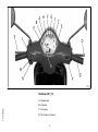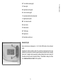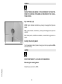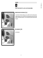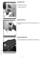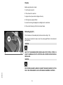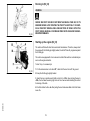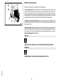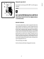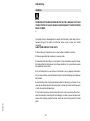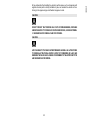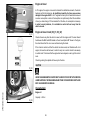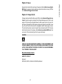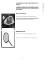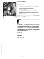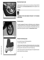
1
Vespa would like to thank you
for choosing one of its products. We have prepared this manual to help you to get the very best from your scooter. Please read it carefully before riding
the scooter for the first time. It contains information, tips and precautions for using your scooter. It also describes features, details and devices to assure
you that you have made the right choice. We believe that if you follow our suggestions, you will soon get to know your new vehicle and it will serve you
well for a long time to come. This booklet forms an integral part of the scooter; should the scooter be sold, it must be transferred to the new owner.
VESPA Vespa LX 50 4T
The instructions given in this manual are intended to provide a clear, simple guide to using your scooter; this booklet also details routine maintenance
procedures and regular checks that should be carried out on the vehicle at an authorised Dealer or Service Centre. The booklet also contains
instructions for simple repairs. Any operations not specifically described in this manual require the use of special tools and/or particular technical
knowledge: to carry out these operations refer to any authorised Dealer of Service Centres.
2
Personal safety
Failure to completely observe these instructions will result in serious risk of personal
injury.
Safeguarding the environment
Sections marked with this symbol indicate the correct use of the vehicle to prevent damaging the environment.
Vehicle intactness
The incomplete or non-observance of these regulations leads to the risk of serious
damage to the vehicle and sometimes even the invalidity of the guarantee.
The signs that you see on this page are very important. They are used to highlight those
parts of the booklet that should be read with particular care. As you can see, each sign
consists of a different graphic symbol, making it quick and easy to locate the various
topics.
3
4
INDEX
VEHICLE......................................................................................
Dashboard................................................................................
Clock.........................................................................................
Key switch.................................................................................
Locking the steering wheel....................................................
Releasing the steering wheel................................................
Switch direction indicators........................................................
Horn button...............................................................................
Light switch...............................................................................
Start-up button..........................................................................
Opening the saddle...............................................................
Keys..........................................................................................
Identification..............................................................................
Rear top box opening................................................................
Bag clip.....................................................................................
USE..............................................................................................
Checks......................................................................................
Refuelling..................................................................................
Tyre pressure............................................................................
Running in.................................................................................
Starting up the engine...............................................................
Precautions...........................................................................
Difficult start up.........................................................................
Stopping the engine..................................................................
Automatic transmission.............................................................
Safe driving...............................................................................
MAINTENANCE...........................................................................
Engine oil level..........................................................................
Engine oil level check............................................................
Engine oil top-up...................................................................
Engine oil change..................................................................
Hub oil level..............................................................................
Tyres.........................................................................................
7
8
9
10
10
10
11
11
12
12
12
13
13
14
14
15
16
16
17
18
18
19
20
21
21
22
25
26
26
27
27
28
29
Spark plug dismantlement........................................................
Removing the air filter...............................................................
Secondary air system...............................................................
Checking the brake oil level......................................................
Battery.......................................................................................
Checking the electrolyte level................................................
Long periods of inactivity..........................................................
Fuses........................................................................................
Front light group........................................................................
Headlight adjustment.............................................................
Front direction indicators...........................................................
Rear optical unit........................................................................
Rear turn indicators...................................................................
Rear-view mirrors......................................................................
Idle adjustment..........................................................................
Front disc brake........................................................................
Rear drum brake.......................................................................
Puncture....................................................................................
Periods of inactivity...................................................................
Cleaning the vehicle..................................................................
TECHNICAL DATA......................................................................
Kit equipment............................................................................
SPARE PARTS AND ACCESSORIES........................................
Warnings...................................................................................
PROGRAMMED MAINTENANCE...............................................
Scheduled maintenance table...................................................
5
30
31
32
33
34
35
36
37
39
39
40
40
41
41
42
43
44
44
44
45
49
52
53
54
55
56
6
VESPA Vespa
LX 50 4T
Chap. 01
Vehicle
7
01_01
Dashboard (01_01)
A = Speedometer
1 Vehicle
B = Odometer
C = Fuel gauge
D = Front brake control lever
8
F = Preset light
G = High-beam warning light
H = Low fuel warning light
I = Low-beam/position light warning light
L = High/low beam switch
M = Turn indicator switch
N = Horn button
P = Starter button
Q = Throttle grip
R = Digital clock
S = Real brake control lever
Clock (01_02)
Hours and minutes are displayed in a 1 to 12, AM or PM, format on the instrument
panel.
Operating the function selection switch «T» month, day and seconds can be seen
besides hours and minutes. In order to adjust the above mentioned functions, operate
button «U». The digital clock is powered by a battery (battery life is about 2 years); lift
the whole instrument panel to replace the battery. It is advisable to take your vehicle
to an Authorised Service Centre for this operation.
01_02
9
1 Vehicle
E = Turn indicator warning light
WARNING
DEAD BATTERIES ARE HARMFUL TO THE ENVIRONMENT. THEY MUST DISPOSED OF IN SUITABLE CONTAINERS AS PRESCRIBED BY THE REGULATIONS IN FORCE.
Key switch (01_03)
LOCK = Ignition disabled, extractable key, steering lock engaged front glove-box
locked.
OFF = Ignition disabled, extractable key, steering lock disengaged, front glove-box
unlocked.
ON = Starter position, antitheft device disabled, non-extractable key, glove-box unlocked.
01_03
Locking the steering wheel
Turn the handlebar to the left (as far as it will go), turn the key to position «LOCK»
and remove the key.
CAUTION
DO NOT TURN THE KEY TO «LOCK» OR «OFF» WHILE RIDING.
Releasing the steering wheel
1 Vehicle
Reinsert the key and turn it to «OFF».
10
DO NOT TURN THE KEY TO «LOCK» OR «OFF» WHILE RIDING.
Switch direction indicators (01_04)
To set the left turn indicators flashing, move lever «B» to the left; to set the right turn
indicators flashing, move it to the right. The lever automatically returns to the central
position and the indicators remain on. To turn the indicators off, press the lever towards
the switch.
01_04
Horn button (01_05)
Horn button «E»
01_05
11
1 Vehicle
CAUTION
Light switch (01_06)
0 = Dipped beam and position light
1 = High beam and position light
01_06
Start-up button (01_07)
To start the engine, press the starter button, «P», after pulling either one of the two
brake levers.
01_07
Opening the saddle (01_08)
1 Vehicle
Insert the key into the saddle lock «A», turn it anticlockwise and tip the saddle forward.
01_08
12
The vehicle is supplied with two keys (one spare) which serve to start the engine and
unlock the saddle compartment. The keys are accompanied by a tag marked with the
identification code to be quoted when ordering duplicates.
WARNING
WE RECOMMEND KEEPING THE DUPLICATE KEY TOGETHER WITH ITS CODE
IN A SAFE PLACE AND NOT ON THE VEHICLE
01_09
Identification (01_10, 01_11)
The identification numbers consist of a prefix stamped on the chassis and on the engine, followed by a number. They should always be given when requesting spare
parts. We recommend that you check that the prefix and chassis number stamped on
the vehicle correspond with those in the vehicle documents.
CAUTION
01_10
BE REMINDED THAT ALTERING IDENTIFICATION REGISTRATION NUMBERS
CAN LEAD TO SERIOUS PENAL SANCTIONS (IMPOUNDING OF THE VEHICLE,
ETC.).
01_11
13
1 Vehicle
Keys (01_09)
Rear top box opening (01_12)
Turn the key to the position«OFF». Then press it. With the key is in «LOCK» the glovebox is locked.
01_12
Bag clip (01_13)
To use the retractable bag hook «B» located at the front end of the saddle, pull it
forward lightly.
1 Vehicle
01_13
14
VESPA Vespa
LX 50 4T
Chap. 02
Use
15
Checks
Before using the vehicle, check:
1. that the fuel tank is full.
2. The oil level in the rear hub.
3. engine oil level (see section «Engine oil level»).
4. That tyres are properly inflated.
5. correct functioning of headlights, rear taillight and turn indicators.
6. The correct functioning of the front and rear brakes.
Refuelling (02_01)
Fill fuel tank«A» with unleaded petrol (minimum octane rating = 95).
When the fuel reaches the reserve level, the warning light fitted on the instrument
panel lights up.
CAUTION
02_01
SHUT OFF THE ENGINE BEFORE REFUELLING WITH PETROL. PETROL IS
HIGHLY FLAMMABLE. DO NOT LET PETROL SPILL FROM THE TANK OR WHILE
REFUELLING
CAUTION
2 Use
DO NOT BRING NAKED FLAMES OR CIGARETTES NEAR THE MOUTH OF THE
FUEL TANK: FIRE HAZARD. ALSO AVOID INHALING HARMFUL VAPOURS.
16
2 Use
CAUTION
USING OILS OTHER THAN THOSE RECOMMENDED CAN SHORTEN THE LIFE
OF THE ENGINE.
Characteristic
Fuel tank capacity
~ 8.5 l (2 l of which is reserve)
Tyre pressure
CAUTION
TYRE PRESSURE SHOULD BE CHECKED WHEN TYRES ARE COLD.INCORRECT TYRE PRESSURE CAUSES ABNORMAL TYRE WEAR AND MAKES RIDING DANGEROUS.
TYRES MUST BE REPLACED WHEN THE TREAD REACHES THE WEAR LIMITS
SET FORTH BY LAW.
Characteristic
Front tyre pressure
1.6 bar
Rear tyre pressure
2 bar
17
Running in (02_02)
WARNING
02_02
DURING THE FIRST 1000 KM DO NOT RIDE THE VEHICLE OVER 80% OF ITS
MAXIMUM SPEED. AVOID TWISTING THE THROTTLE GRIP FULLY OR KEEPING A CONSTANT SPEED ALONG LONG SECTIONS OF ROAD. AFTER THE
FIRST 1000 KM, GRADUALLY INCREASE SPEED UNTIL REACHING THE MAXIMUM PERFORMANCE.
Starting up the engine (02_03)
The vehicle is fitted with direct drive automatic transmission. Therefore, always start
the engine with the throttle grip slightly twisted; to start-off from still, progressively twist
the throttle grip.
The vehicle is equipped with a fuel valve and a starter that switch on automatically as
soon as the engine is started.
To start it up, it is necessary to:
1: Put the motorscooter on its stand "E"; check that the rear tire is off the ground.
02_03
2: Keep the throttle grip slightly twisted.
3: Insert the key in ignition switch «D» and turn it to «ON»; when turning the key to
«ON», the fuel reserve warning light turns on for a few seconds indicating the correct
functioning of the bulb.
2 Use
4: Push the starter button «A» after pulling the rear brake lever «B» or the front brake
lever «C».
18
2 Use
CAUTION
DO NOT CARRY OUT THESE OPERATIONS IN CLOSED AREAS SINCE EXHAUST GASES ARE TOXIC.
CAUTION
ALWAYS PLACE THE VEHICLE ON ITS STAND BEFORE KICK STARTING.
Precautions
CAUTION
NEVER STRESS THE ENGINE AT LOW TEMPERATURES IN ORDER TO AVOID
POSSIBLE DAMAGE. BE CAREFUL NEVER TO EXCEED THE MAXIMUM SPEED
WHILE RUNNING DOWNHILL, IN ORDER TO AVOID DAMAGING THE ENGINE.
IN ANY CASE, IN ORDER TO PRESERVE THE ENGINE FROM PROLONGED EXCESSIVE REVOLUTIONS, THE REVOLUTION LIMITER WILL BE ACTIVATED IF
THE ENGINE SPEED EXCEEDS THE ESTABLISHED THRESHOLD.
WARNING
AFTER A LONG DISTANCE COVERED AT THE MAXIMUM SPEED, DO NOT STOP
THE ENGINE IMMEDIATELY, BUT LET IT RUN AT IDLE FOR A FEW SECONDS.
19
Difficult start up (02_04)
If there is a problem you can follow the instructions below:
1.Carburettor flooded. Place the vehicle on the centre stand and check that the rear
tyre is off the ground. Open the throttle fully and press the starter button for five seconds and then stop for five seconds. If the engine does not start after a few attempts,
let the engine sit for a few minutes and then repeat the above operations. In any case
do not operate the starter longer than 20" in the attempt to start the engine.
02_04
2. Battery or starter motor inefficiency. Put the motorscooter on its stand "E"; make
sure that the rear wheel is off the ground, turn the key switch «D» to «ON» and use
the kick-starter «F».
3. Empty fuel tank. After refuelling the scooter, start the engine by pressing the starter
button «A» with the throttle at a minimum to provide maximum aspiration for the tap.
If the scooter fails to start even after taking the steps described above, contact an
Authorised Piaggio Service Centre.
CAUTION
ALWAYS PLACE THE VEHICLE ON ITS STAND BEFORE KICK STARTING.
WARNING
2 Use
TAMPERING MAY CAUSE SERIOUS ENGINE MALFUNCTION.
20
Stop acceleration, then turn the key switch "D" to "OFF " to turn off the engine (extractable key).
CAUTION
02_05
DUE TO THE HIGH TEMPERATURES THE CATALYTIC CONVERTER CAN
REACH, ALWAYS TAKE CARE, WHEN PARKING THE SCOOTER, THAT THE
EXHAUST DOES NOT COME INTO CONTACT WITH FLAMMABLE MATERIALS,
TO AVOID SERIOUS BURNS.
Automatic transmission
To ensure simple, pleasurable riding, the vehicle is equipped with automatic transmission with regulator and centrifugal clutch. The system is designed to give the best
possible performance in terms of both acceleration and consumption, on level ground
and uphill, thanks to the adjustments made to engine speed and transmitted torque.
If you have to stop on an uphill slope (traffic lights, traffic jam, etc.) only use the brake
to keep the vehicle still, leaving the motor running at idling speed. Using the motor to
keep the vehicle still can cause the clutch to overheat. This problem is due to the
friction of the clutch parts on the clutch bell. It is therefore recommended to avoid
conditions of prolonged clutch slippage leading to clutch overheating (for example, as
well as the situation described above, riding uphill fully laden on steep slopes or starting off on slopes greater than 25%, etc.):
1. Do not continue riding in such conditions.
2. Let the clutch cool down with the motor at idling speed for a few minutes.
21
2 Use
Stopping the engine (02_05)
Safe driving
WARNING
SOME SIMPLE TIPS ARE PROVIDED BELOW THAT WILL ENABLE YOU TO USE
YOUR SCOOTER ON A DAILY BASIS IN GREATER SAFETY AND WITH MORE
PEACE OF MIND.
<
Your ability and your knowledge of the vehicle form the basis of safe riding. We recommend trying out the vehicle in traffic-free zones to get to know your vehicle
completely.
ALWAYS DRIVE WITHIN YOUR LIMITS
1. Before riding off, remember to put on your helmet and fasten it correctly.
2. Reduce speed and ride cautiously on uneven roads.
3. Remember that after riding on a long stretch of wet road without using the brakes,
the braking effect is initially lower. Given these conditions, it is a good idea to operate
the brakes from time to time.
4. Do not brake hard on a wet surface, on dirt tracks or on any slippery road surface.
5. If you have to brake, use both brakes in order to divide the braking action between
both wheels.
6. Avoid starting off by mounting the scooter while it is still resting on its stand. In any
case, the rear wheel should not be turning when in comes into contact with the ground,
in order to avoid abrupt departures.
2 Use
7. If the vehicle is used on roads covered with sand, mud, snow mixed with salt, etc.,
clean the brake disc frequently with mild detergent in order to prevent abrasive substances from building up within the holes, which can result in early wear of the brake
pads.
22
CAUTION
DO NOT FORGET THAT DRIVING IN A STATE OF DRUNKENNESS, OR WHEN
UNDER THE EFFECT OF DRUGS OR CERTAIN MEDICINES, CAN BE EXTREMELY DANGEROUS FOR ONESELF AND FOR OTHERS.
CAUTION
ANY CHANGES TO THE VEHICLE PERFORMANCE AS WELL AS ALTERATIONS
TO ORIGINAL STRUCTURAL PARTS IS STRICTLY FORBIDDEN BY LAW, AND
RENDERS THE VEHICLE NO LONGER CONFORMING TO THE APPROVED TYPE
AND DANGEROUS FOR RIDING.
23
2 Use
8. Any elaboration that modifies the vehicle's performances, such as tampering with
original structural parts is strictly forbidden by law, and renders the vehicle not conforming to the approved type and therefor dangerous to ride.
24
2 Use
VESPA Vespa
LX 50 4T
Chap. 03
Maintenance
25
Engine oil level
In 4T engines, the engine oil is used to lubricate the distribution elements, the bench
bearings and the thermal group. An insufficient quantity of oil can cause serious
damage to the engine itself. In all 4T engines the decay of oil characteristics as well
as some consumption is normal. Consumption can particularly reflect the conditions
of use (i.e. when driving at "full acceleration" all the time, oil consumption increases).
In order to avoid problems, it is advisable to control oil level every time the
vehicle is used.
03_01
Engine oil level check (03_01, 03_02)
Check oil level every time the vehicle is used, with the engine cold. The level should
be between the MAX and MIN marks on the oil level dipstick "A" shown in the figure;
the stand should be firm on an even surface during the check.
If the check is carried out after the vehicle has been used, and therefore with a hot
engine, the level line will be lower; in order to carry out a correct check it is necessary
to wait at least 10 minutes after the engine has been stopped, so as to get the correct
level.
Check by pushing the dipstick all the way into the hole.
CAUTION
03_02
USING THE ENGINE WITH INSUFFICIENT LUBRICATION OR WITH THE WRONG
LUBRICANTS MAY INCREASE WEAR AND TEAR ON THE MOVING PARTS AND
MAY CAUSE SERIOUS DAMAGE.
3 Maintenance
Characteristic
Engine oil
Capacity: ~ 850 cc
03_03
26
Always check oil level before carrying out top-ups and add oil without exceeding the
MAX level. An engine oil check-up and top-up should be carried out every 3,000 km
at an Authorised Piaggio Service Centre.
Engine oil change (03_03)
Change oil and clean the filter after every 6,000 km at an Authorised Piaggio Service
Centre. Empty the engine by draining the oil through drainage cap «C» with a cold
engine. First unscrew the cap-dipstick used to check engine oil level, then cap «C»
and take out the mesh filter. After cleaning and mounting again the mesh filter, screw
cap «C» and fill with oil the hole of the cap-dipstick used to check engine oil level.
Then start up the scooter, leave it running for a few minutes and switch it off: 5 minutes
later check oil level and, if necessary, add oil without exceeding the MAX level. Only
use new oil of the recommend type for oil top-ups and change.
CAUTION
USED OILS CONTAIN SUBSTANCES HARMFUL TO THE ENVIRONMENT. FOR
OIL REPLACEMENT, CONTACT AN AUTHORISED PIAGGIO SERVICE CENTRE,
AS THEY ARE EQUIPPED TO DISPOSE OF SPENT OILS IN AN ENVIRONMENTALLY FRIENDLY AND LEGAL WAY.
Recommended products
AGIP CITY HI TEC 4T
Engine oil
SAE 5W-40, API SL, ACEA A3, JASO MA Synthetic oil
27
3 Maintenance
Engine oil top-up
Hub oil level (03_04, 03_05, 03_06)
To check the hub oil level, proceed as follows:
1. Place the scooter on its stand on a level surface;
2. Unscrew the dipstick «A», dry it with a clean rag and then reinsert it, screwing it tightly into place;
3. Unscrew the dipstick again and check that the oil level barely reaches the
2nd notch from the bottom;
4. Screw the dipstick back into place completely.
The screw «B» is the hub oil drainage tap.
03_04
CAUTION
USING THE ENGINE WITH INSUFFICIENT LUBRICATION OR WITH THE WRONG
LUBRICANTS MAY INCREASE WEAR AND TEAR ON THE MOVING PARTS AND
MAY CAUSE SERIOUS DAMAGE.
CAUTION
03_05
USED OILS CONTAIN SUBSTANCES HARMFUL TO THE ENVIRONMENT. FOR
OIL REPLACEMENT, CONTACT AN AUTHORISED SERVICE CENTRE, WHICH
IS EQUIPPED TO DISPOSE OF USED OILS IN AN ENVIRONMENTALLY FRIENDLY AND LEGAL WAY.
3 Maintenance
03_06
N.B.
THE NOTCHES ON THE HUB OIL LEVEL DIPSTICK, EXCEPT THOSE INDICATING THE MAXIMUM AND MINIMUM LEVELS, REFER TO OTHER MODELS BY
THE MANUFACTURER, AND HAVE NO SPECIFIC FUNCTION FOR THIS MODEL.
Recommended products
AGIP ROTRA 80W-90
Rear hub oil
28
Characteristic
Rear hub oil
Quantity: approx. 85 cc
Tyres (03_07)
Periodically check the inflation pressure of each tyre (when cold). The tyres are fitted
with a wear indicator and must be replaced as soon as such indicator appears on the
tread. Also ensure that the tyres do not show cuts on the walls or an irregular wear of
the tread; if this is the case, please contact an authorised or adequately equipped
workshop.
CAUTION
03_07
TYRE PRESSURE SHOULD BE CHECKED WHEN TYRES ARE COLD.INCORRECT TYRE PRESSURE CAUSES ABNORMAL TYRE WEAR AND MAKES RIDING DANGEROUS.
TYRES MUST BE REPLACED WHEN THE TREAD REACHES THE WEAR LIMITS
SET FORTH BY LAW.
Characteristic
Front tyre pressure
1.6 bar
Rear tyre pressure
2 bar
29
3 Maintenance
SAE 80W/90 Oil that exceeds the requirements of API GL3 specifications
Spark plug dismantlement (03_08, 03_09, 03_10, 03_11)
The engine must be cold to inspect the sparkplug, proceed as follows:
1. Lift the saddle and remove the helmet compartment "A";
2. Remove the sparkplug inspection door "B";
3. Remove plug cap "C";
4. Use the equipped spanner "D"(with rubber stop) and a 13 mm spanner to remove
the sparkplug.
03_08
To reassemble repeat the procedure in the opposite order using the spanner to insert
the sparkplug and to tighten it in its seat, making sure to install it and screw it down at
the correct angle.
The above operations need to be carried out very carefully by inserting the left hand
from the sparkplug inspection door and the right hand from the helmet compartment.
To reassemble the door carry out the operations in the opposite order, making sure
to insert the tab in the part of the central covering.
WARNING
03_09
THE SPARK PLUG MUST BE REMOVED WHEN THE ENGINE IS COLD. THE USE
OF A SPARK PLUG WITH THERMAL GRADE OR THREAD OTHER THAN THE
INDICATED TYPE (SEE «DATA» SECTION) CAN SERIOUSLY DAMAGE THE ENGINE. REPLACE SPARK PLUGS AT THE INTERVALS INDICATED IN THE
SCHEDULED MAINTENANCE TABLE.
3 Maintenance
N.B.
THE USE OF SPARK PLUGS OTHER THAN THE INDICATED TYPE OR OF
SHIELDLESS SPARK PLUG CAPS CAN CAUSE ELECTRICAL SYSTEM FAILURES.
03_10
Characteristic
Spark plug
30
3 Maintenance
NGK CR 8EB
03_11
Removing the air filter (03_12, 03_13)
Remove the side fairing unscrewing the 2 screws marked A. Remove the air cleaner
cap «D» after unscrewing the 6 fixing screws «C», then remove the filtering element.
Clean with water and shampoo, afterwards dry with compressed air and submerge in
a recommended oil and petrol mixture in ratio of 50%. Afterwards squeeze it, leave it
to dry and mount it again.
CAUTION
03_12
IN CASE OF RIDING ON DUSTY ROADS IT IS ADVISABLE TO CLEAN THE AIR
FILTER MORE FREQUENTLY THAN INDICATED IN THE RELEVANT CHAPTER
ON SCHEDULED MAINTENANCE.
03_13
31
Secondary air system (03_14, 03_15, 03_16, 03_17)
Use the two screws "A" on the right side panel and remove it. Use the three screws
"B" to remove the cover of the secondary air box. Move the cover of the box away and
remove the sponge filter "C". Wash the sponge with water and a neutral soap, and dry
it with a clean rag and shorts blasts of compressed air. When cleaning the filter, make
sure the reed valve "D" is in good condition then reinsert it in its seat on the box.
Before closing the SAS box cover, check the condition of the O-ring seal; replace it if
it appears damaged or deformed.
N.B.
03_14
The reed valve can be inserted in only one direction on the SAS housing
3 Maintenance
03_15
03_16
32
3 Maintenance
03_17
Checking the brake oil level (03_18, 03_19)
The brake fluid reservoir is equipped with a sight glass «A» made of transparent material; the quantity of liquid contained in the sight glass indicates the level of liquid in
the reservoir.
When the sight glass «A» is full, the level inside the reservoir exceeds the MIN level;
when it is partially full, the level drops to the MIN level; when it is fully empty, the level
of fluid in the reservoir is below the MIN level.
03_18
The brake fluid level may fall due to wear on the brake pads. In case the pad wear is
below the minimum mark, contact an Authorised Service Centre to have the braking
system thoroughly checked. If you need to top up the level, follow the steps listed
below. Unscrew the 2 screws "B", remove the tank cap "C" and pour in the required
quantity of fluid (the brake fluid level must be above minimum). Place the handlebar
in the riding position and pay attention not to tilt the vehicle in order to keep the brake
fluid reservoir in horizontal position when checking the fluid level.
CAUTION
TOP UPS SHOULD ONLY BE CARRIED OUT WITH DOT 4 CLASSIFIED BRAKE
FLUID.
33
WARNING
IN NORMAL CLIMATIC CONDITIONS IT IS ADVISABLE TO REPLACE THE
ABOVE-MENTIONED FLUID EVERY 2 YEAR. NEVER USE BRAKE FLUID CONTAINED IN CONTAINERS WHICH ARE ALREADY OPEN OR PARTIALLY USED.
CAUTION
03_19
THE BRAKING CIRCUIT FLUID IS HIGHLY CORROSIVE. THEREFORE, WHEN
TOPPING IT UP, AVOID LETTING IT COME INTO CONTACT WITH THE PAINTED
PARTS OF THE VEHICLE. THE BRAKING CIRCUIT FLUID IS HYGROSCOPIC,
WHICH MEANS THAT IT ABSORBS MOISTURE FROM THE SURROUNDING AIR.
IF MOISTURE CONTAINED IN THE BRAKE FLUID EXCEEDS A CERTAIN VALUE,
THIS WILL RESULT IN INEFFICIENT BRAKING.
Battery (03_20)
To access the battery, tilt the saddle forwards, then remove the battery compartment
access door by unscrewing the star-shaped screw "A" shown in the figure.
The battery is the electrical device that requires the most frequent attention and the
most thorough maintenance.
3 Maintenance
WARNING
03_20
SPENT BATTERIES ARE HARMFUL FOR THE ENVIRONMENT. COLLECTION
AND DISPOSAL SHOULD BE CARRIED OUT IN COMPLIANCE WITH CURRENT
REGULATIONS.
34
ELECTROLYTE CONTAINS SULPHURIC ACID: AVOID CONTACT WITH EYES,
SKIN AND CLOTHES. IN THE CASE OF ACCIDENTAL CONTACT, RINSE WITH
ABUNDANT OF WATER AND CONSULT A DOCTOR.
CAUTION
IN ORDER TO AVOID DAMAGING THE ELECTRICAL SYSTEM, NEVER DISCONNECT THE WIRING WHILE THE ENGINE IS RUNNING. DO NOT TIP THE SCOOTER TOO MUCH IN ORDER TO AVOID DANGEROUS LEAKAGE OF BATTERY
ELECTROLYTE
.
Checking the electrolyte level
The electrolyte level, which should be checked regularly, must always be at the maximum level. To reach this level, use only distilled water. Should it become necessary
to top up the battery with water too frequently, check the scooter's electrical system
because the battery is being overloaded, causing it to lose power quickly.
CAUTION
ELECTROLYTE CONTAINS SULPHURIC ACID: AVOID CONTACT WITH EYES,
SKIN AND CLOTHES. IN THE CASE OF ACCIDENTAL CONTACT, RINSE WITH
ABUNDANT OF WATER AND CONSULT A DOCTOR.
35
3 Maintenance
CAUTION
Long periods of inactivity
Battery performance will decrease if the vehicle is not used for a long time. This is the
result of the natural phenomenon of battery discharging plus residual absorption by
vehicle components with constant power consumption. Poor battery performance may
also be due to environmental conditions and the cleanness of the poles. In order to
avoid difficult starts and/or irreversible damage to the battery, follow any of these
steps:
- At least once a month start the engine and run it slightly above idle speed for 10-15
minutes. This keeps all the engine components, as well as the battery, in good working
order.
- Take your vehicle to a garage (as indicated in the "Vehicle not used for extended
periods" section) to have the battery removed. Have the battery cleaned, charged fully
and stored in a dry, ventilated place. Recharge at least once every two months.
N.B.
THE BATTERY MUST BE CHARGED WITH A CURRENT EQUAL TO 1/10 OF THE
RATED CAPACITY OF THE BATTERY AND FOR NOT LONGER THAN 10 HOURS.
CONTACT AN AUTHORISED SERVICE CENTRE TO CARRY OUT THIS OPERATION SAFELY. WHEN REFITTING THE BATTERY MAKE SURE THE LEADS ARE
CORRECTLY CONNECTED TO THE TERMINALS.
WARNING
3 Maintenance
DO NOT DISCONNECT THE BATTERY CABLES WITH THE ENGINE RUNNING,
THIS CAN CAUSE PERMANENT DAMAGE TO THE VEHICLE ELECTRONIC CONTROL UNIT.
36
SPENT BATTERIES ARE HARMFUL FOR THE ENVIRONMENT. COLLECTION
AND DISPOSAL SHOULD BE CARRIED OUT IN COMPLIANCE WITH CURRENT
REGULATIONS.
Fuses (03_21)
The electrical system is protected by a 10A fuse valve «B» located next to the battery.
Before replacing a blown fuse, find and solve the problem that caused it to blow. Do
not substitute the fuse with any alternative form of conductor
CAUTION
03_21
IN ORDER TO AVOID DAMAGING THE ELECTRICAL SYSTEM, NEVER DISCONNECT THE WIRING WHILE THE ENGINE IS RUNNING. DO NOT TIP THE SCOOTER TOO MUCH IN ORDER TO AVOID DANGEROUS LEAKAGE OF BATTERY
ELECTROLYTE
.
BULB
High/low beam light bulb
Type: Spherical
Power: 12V 35/35W
Quantity: 1
Front tail light bulb
Type: All glass
37
3 Maintenance
WARNING
Power: 12V 5W
Quantity: 1
Instrument panel light bulbs
Type: All glass
Power: 12V 1.2W
Quantity: 3
Front turn indicator bulb
Type: Spherical
Power: 12V - 10W
Quantity: 1 RHS + 1 LHS
Rear turn indicator light bulb
Type: Spherical
Power: 12V - 10W
Quantity: 1 RHS + 1 LHS
Stop and tail light bulb
Type: Spherical
Power: 12V 21/5W
Quantity: 1
12V - 2W warning light bulbs
Type: All glass
Function: Turn indicators
3 Maintenance
Quantity: 2
12V - 1.2W warning light bulb
Type: All glass
Function:
Lights,
lights, fuel reserve
high-beam
Quantity: 3
38
To access the headlight bulbs, remove the front of the handlebar cover, as follows:
1) Remove the rear-view mirrors; for this operation follow the instructions described
and illustrated in «Rear-view mirrors» section.
2) Unscrew the 3 screws holding the handlebar cover. The front central one «B» and
the rear 2 «C». Once this is done, the handlebar cover can be removed.
3) Remove the handlebar cover to access the headlight and the bulbs.
03_22
N.B.
IF MISTING IS NOTICED ON THE INSIDE OF THE HEADLAMP GLASS, THIS
DOES NOT INDICATE A FAULT AND IS RELATED TO THE HUMIDITY AND/OR
TO LOW TEMPERATURES.
THE PHENOMENON SHOULD QUICKLY DISAPPEAR WHEN THE LIGHT IS
SWITCHED ON.
THE PRESENCE OF DROPS OF WATER, ON THE OTHER HAND, COULD INDICATE THAT WATER IS INFILTRATING. CONTACT THE PIAGGIO AFTER-SALES
SERVICE NETWORK.
03_23
Electric characteristic
Bulbs
1 12V35/35W bulb for high- and low-beam light
1 12V-5W bulb for tail light
Headlight adjustment (03_24, 03_25)
Proceed as follows:
03_24
1. Place the vehicle in running order and with the tyres inflated to the prescribed pressure, on a flat surface 10 m away from a white screen situated in a shaded area,
making sure that the longitudinal axis of the scooter is perpendicular to the screen;
39
3 Maintenance
Front light group (03_22, 03_23)
2. Turn on the headlight and check that the borderline of the projected light beam on
the screen is not lower than 9/10 of the distance from the ground to the centre of
vehicle headlamp and higher than 7/10;
3. If otherwise, adjust the right headlight with screw «A».
N.B.
THE ABOVE PROCEDURE COMPLIES WITH THE EUROPEAN STANDARDS REGARDING MAXIMUM AND MINIMUM HEIGHT OF LIGHT BEAMS. REFER TO THE
STATUTORY REGULATIONS IN FORCE IN EVERY COUNTRY WHERE THE vehicle IS USED.
03_25
Front direction indicators (03_26)
To replace the front turn indicator bulbs, remove the tail light taking out the retaining
screw "A", remove the bulb holder from its fitting; gently turn the bulb around 30º and
remove it. Follow the process in reverse order to refit.
03_26
Rear optical unit (03_27)
To access the rear taillight bulb it is necessary to remove the 2 fixing screws «D».
Gently push and turn the bulb about 30° and then remove it. To refit follow the same
steps but in reverse order.
3 Maintenance
N.B.
IF MISTING IS NOTICED ON THE INSIDE OF THE HEADLAMP GLASS, THIS
DOES NOT INDICATE A FAULT AND IS RELATED TO THE HUMIDITY AND/OR
TO LOW TEMPERATURES.
03_27
40
THE PRESENCE OF DROPS OF WATER, ON THE OTHER HAND, COULD INDICATE THAT WATER IS INFILTRATING. CONTACT THE PIAGGIO AFTER-SALES
SERVICE NETWORK.
Rear turn indicators (03_28)
To gain access to the turn indicator bulbs, remove the fastening screws «E».
The bulbs have a bayonet coupling, to remove them press gently and twist anticlockwise about 30°. To refit follow the same steps but in reverse order.
03_28
Rear-view mirrors (03_29)
The mirrors can be set to the desired position by adjusting the mirror frame.
To remove the rear-view mirror rotate the rear-view mirror support rod clockwise.
03_29
41
3 Maintenance
THE PHENOMENON SHOULD QUICKLY DISAPPEAR WHEN THE LIGHT IS
SWITCHED ON.
Idle adjustment (03_30)
Proceed as follows:
1. Rest the scooter on its centre stand and lift the saddle (as described in the
«Saddle opening to reach helmet compartment» section).
2. Remove the helmet compartment.
3. To adjust the idle speed, start the engine, then loose or tighten the screw
«B» until you reach the recommended idle speed taking care the engine does
not make the rear wheel move.
03_30
If adjustment is difficult, take your vehicle to a Dealer or an Authorised PIAGGIO
Service Centre to adjust CO to idle speed.
WARNING
IDLE SPEED MUST BE ADJUSTED WHEN THE ENGINE IS VERY HOT. BEFORE
THIS OPERATION, MAKE SURE THAT THE THROTTLE GRIP HAS THE RECOMMENDED BACKLASH. IF BACKLASH IN THE THROTTLE CONTROL TRANSMISSION NEEDS ADJUSTING TAKE YOUR SCOOTER TO A PIAGGIO DEALER
OR AUTHORISED SERVICE CENTRE
Characteristic
Engine idle speed
3 Maintenance
approx. 1600 ÷ 1800 rpm
42
The brake disc and pad wear is automatically compensated, therefore it has no effect
on the functioning of the front and rear brakes. For this reason it is not necessary to
adjust the brakes. An excessively elastic brake lever stroke may indicate the presence
of air in the braking circuit or an irregular brake operation. In this case, particularly
considering the importance of the brakes in terms of safety, it is strongly recommended
that you take the vehicle to an Authorised Service Centre as soon as possible for
the appropriate checks.
WARNING
03_31
CHECK BRAKE PADS FOR WEAR ON A REGULAR BASIS (AS INDICATED IN
THE SCHEDULE MAINTENANCE TABLES). IF THE THICKNESS OF ONE OR
BOTH PADS IS IN THE REGION OF 1.5 MM, BOTH PADS MUST BE CHANGED.
IT IS RECOMMENDED TO CARRY OUT THIS OPERATION AT AN AUTHORISED
SERVICE CENTRE AS SOON AS POSSIBLE.
AFTER FITTING NEW BRAKE PADS DO NOT USE THE VEHICLE UNTIL YOU
HAVE ACTIVATED THE BRAKE LEVER REPEATEDLY TO POSITION THE PADS
AND RESTORE THE LEVER STROKE TO ITS CORRECT POSITION.
CAUTION
THE BRAKING ACTION SHOULD BEGIN AFTER ABOUT 1/3 OF THE BRAKE
LEVER STROKE.
43
3 Maintenance
Front disc brake (03_31)
Rear drum brake (03_32)
Operate adjustment nut «B» and loosen lock nut «A» shown in the figure. Note that
when the throttle is in idle the wheel should rotate free. After the adjustment, screw
lock nut «A».
CAUTION
03_32
THE BRAKING ACTION SHOULD BEGIN AFTER ABOUT 1/3 OF THE BRAKE
LEVER STROKE.
Puncture (03_33)
The vehicle is equipped with Tubeless tyres. When there is a puncture, Tubeless tyres
- unlike tyres with inner tubes - go flat very slowly. This offers greater riding safety. A
tyre that goes flat very slowly can be repaired with an "Inflate and Repair" spray. Tyres
should be later fully repaired or replaced at an Authorised Service Centre.
03_33
Periods of inactivity (03_34)
3 Maintenance
We recommend carrying out the following operations:
1. General cleaning of the vehicle.
2 - With the engine off and the piston at bottom dead centre position, remove the spark
plug and pour 1÷2 cc of motor oil through its hole. Operate the starter 3-4 times letting
the engine perform a few revolutions, then remount the spark plug.
3 - Drain up all the vehicle's fuel; spread antirust grease on the unpainted metal parts;
keep the wheels lifted above the ground.
03_34
44
5 - Drain the petrol from the carburettor tank.
6 - Replace engine oil.
Recommended products
AGIP CITY HI TEC 4T
Oil to lubricate flexible transmissions (brakes, throttle control and odometer)
Oil for 4-stroke engines
Cleaning the vehicle
Use a low pressure jet of water to soften the caked dirt and mud deposited on the
painted surfaces. Once softened, sponge off mud and dirt using a car body sponge
soaked in a car body shampoo and water solution (2-4% of car shampoo in water).
Then rinse abundantly with water, and dry with a shammy cloth. For the outside of the
engine, use petroleum, a brush and clean cloths. Petrol can damage paintwork. Remember that any polishing with silicone wax must always be preceded by washing.
CAUTION
DETERGENTS POLLUTE WATER. THEREFORE THE VEHICLE SHOULD BE
WASHED IN AN AREA EQUIPPED FOR THE COLLECTION AND PURIFICATION
OF THE LIQUIDS USED.
WARNING
NEVER WASH THE VEHICLE UNDER DIRECT SUNLIGHT, ESPECIALLY IN SUMMER WHEN THE BODYWORK IS STILL HOT, AS THE CAR SHAMPOO MAY DRY
BEFORE BEING RINSED OFF, AND COULD DAMAGE THE PAINTWORK. NEVER
USE RAGS SOAKED IN PETROL OR DIESEL OIL TO CLEAN THE PAINTED OR
45
3 Maintenance
4 - For the battery, follow the procedures described in the «Battery» section.
PLASTIC SURFACES, TO PREVENT THEM LOSING THEIR SHINE AND MECHANICAL CHARACTERISTICS.
WARNING
WHEN WASHING THE ENGINE WITH A HIGH-PRESSURE WATER JET:
• ONLY USE FAN SPRAY JETS.
• DO NOT PLACE THE WATER JET NOZZLE CLOSER THAN 60 CM.
• DO NOT USE WATER AT TEMPERATURES OVER 40° C.
• DO NOT DIRECT THE JETS DIRECTLY TO CARBURETTOR, WIRING, SLOT
DIFFUSER ON THE TRANSMISSION COVER AND SCROLL COVER.
DIFFICULTY STARTING
No fuel in tank
Refuelling
Filters, jets or carburettor dirty or
clogged.
Contact an Authorised Service
Centre.
Insufficient battery charge
Kick-start. Recharge the battery.
3 Maintenance
IGNITION PROBLEMS
No spark from spark plug. Due to
the presence of high voltage, this
check should only be carried out by
an expert.
Check that the electrodes are
properly adjusted (0.7÷ 0.8 mm).
Check that the electrodes are
clean (clean with pure petrol and
metal brush or with emery cloth).
Check the spark plug insulator: if
46
3 Maintenance
there are any cracks or breakage,
replace the spark plug. If the spark
plug is in good condition, contact
an Authorised Piaggio Service
Centre.
LACK OF COMPRESSION
Spark plug adapter "worn", valve
clearance not adequate; worn
piston gas rings
Contact an Authorised Service
Centre.
HIGH CONSUMPTION AND LOW PERFORMANCE
Air filter blocked or dirty.
Clean with water and shampoo and
impregnate with petrol and specific
oil (section «Removing the air
filter»)
INEFFICIENT BRAKING
Oil on drum or disc. Worn Pads/
Shoes
Contact an Authorised Service
Centre
incorrect rear brake adjustment
Adjust
INEFFICIENT SUSPENSION
Oil leak; worn limit switch bumpers; Contact an Authorised Service
worn shock absorber attachment Centre
points
47
IRREGULAR AUTOMATIC TRANSMISSION
Deteriorated roller container or
belt.
Contact an Authorised Service
Centre.
INCREASED EXHAUST NOISE
Deterioration of the SAS system
and/or of the tab
Contact an Authorised Service
Centre.
STAND DOES NOT RETURN TO POSITION
Presence of dirt
Clean and grease
STARTER LEVER DOES NOT RETURN TO CORRECT
POSITION
Clean and grease
3 Maintenance
Presence of dirt
48
VESPA Vespa
LX 50 4T
Chap. 04
Technical data
49
4 Technical data
04_01
50
4 Technical data
TECHNICAL SPECIFICATIONS
Engine type
Single cylinder 4-stroke Piaggio HiPER4
Cubic capacity
49.9 cc
Bore x stroke
39 X 41.8 mm
Compression ratio
11.5 :1
Length
1755 mm
Width
740 mm
Overall height
1140 mm
Wheel base
1290 mm.
Fuel
Unleaded petrol
Chassis
Unitised body made of stamped
plate.
Fuel tank capacity
~ 8.5 l (2 l of which is reserve)
Timing system
Single overhead camshaft (SOHC)
with 2 valves
Start up
Electrical and kick starter
Lubrication
Wet crankcase
Cooling
Forced air circulation.
Depression carburettor
KEIHN CVK 18
Spark plug
NGK CR 8EB
Transmission
Automatic variator CVT with torque
server.
Clutch
Automatic centrifugal dry clutch
51
Steering and suspensions
Fulcrum steering tube on the front
wheel-holder hub; helicoidal spring
suspension and double-acting
hydraulic shock absorber; rear with
single chamber hydraulic shock
absorber and coaxial spring not
adjustable at preloading
Rear tyre
Tubeless; 120/70-10"
Front tyre
Tubeless; 110/70-11"
Rear wheel rim
Die-cast aluminium alloy; 3.00 x
10"
Front wheel rim
Die-cast aluminium alloy; 2.50 x11"
Front brake
Disc brake (Ø 200 mm) with
hydraulic control (lever on the far
right of the handlebar) and fixed
calliper.
Rear brake
Ø110 mm drum brake
Homologation
Euro 2
Dry weight
102±5
Kit equipment
4 Technical data
Spanners: one box wrench (16 mm); a double screwdriver. The tools are located in a
toolbox under the saddle.
52
VESPA Vespa
LX 50 4T
Chap. 05
Spare parts and
accessories
53
Warnings (05_01, 05_02)
WARNING
IT IS ALSO RECOMMENDED THAT "ORIGINAL PIAGGIO SPARE PARTS" BE
USED, AS THESE ARE THE ONLY ONES OFFERING YOU THE SAME QUALITY
ASSURANCE AS THOSE INITIALLY FITTED ON THE VEHICLE.
IT SHOULD BE REMEMBERED THAT USING NON-ORIGINAL SPARE PARTS
CAUSES YOUR WARRANTY RIGHTS TO EXPIRE.
WARNING
5 Spare parts and accessories
05_01
PIAGGIO MARKETS ITS OWN LINE OF ACCESSORIES THAT ARE RECOGNISED AND GUARANTEED FOR USE. IT IS THEREFORE ESSENTIAL, IN ORDER
TO CHOOSE AND MOUNT THE ACCESSORIES CORRECTLY, TO CONTACT AN
AUTHORISED DEALER OR SERVICE CENTRE. THE USE OF NON-ORIGINAL
ACCESSORIES MAY AFFECT THE STABILITY AND OPERATION OF YOUR VEHICLE AND REDUCE SAFETY LEVELS WITH POTENTIAL RISKS FOR THE
RIDER.
05_02
54
VESPA Vespa
LX 50 4T
Chap. 06
Programmed
maintenance
55
Scheduled maintenance table
Adequate maintenance is fundamental to ensuring long-lasting, optimum operation
and performance of your vehicle.
To this end, a series of checks and maintenance operations (at the owner's expense)
have been suggested, which are included in the summary table on the following page.
Any minor faults should be reported without delay to an Authorised Service Centre
or Dealer without waiting until the next scheduled service to solve it.
All scheduled maintenance services must be carried out at the specified times, even
if the stated mileage has not yet been reached. Carrying out scheduled services on
time is necessary to ensure your warranty remains valid. For any further information
concerning Warranty procedures and "Scheduled Maintenance", please refer to the
"Warranty Booklet".
EVERY 3,000 KM
Engine oil - level check/ top-up
6 Programmed maintenance
EVERY 2 YEARS
Brake fluid - change
AFTER 1,000 KM OR 4 MONTHS
Hub oil - change
Valve clearance - check
Idle speed (*) - adjustment
Throttle lever - adjustment
56
6 Programmed maintenance
Steering - adjustment
Brake control levers - greasing
Brake pads - check condition and wear
Brake fluid level - check
Safety locks - check
Electrical system and battery - check
Tyre pressure - check
Vehicle and brake test - road test
(*) See instructions in «Idle speed adjustment» section
AT 6000 KM OR 12 MONTHS, 18000, 30000, 42000,
54000 AND 66000 KM
Engine oil - replacement
Hub oil level - check
Spark plug / electrode gap - check
Oil filter (net filter) - clean
Variable speed rollers - check or replacement
Brake pads - check condition and wear
Brake fluid level - check
Electrical system and battery - check
Tyre inflation and wear - Check
Vehicle and brake test - road test
57
AT 12000 KM OR 24 MONTHS AND 60000 KM
Engine oil - replacement
Hub oil level - check
Spark plug/electrode gap - replacement
Air filter - clean
Oil filter (net filter) - clean
Idle speed (*) - adjustment
Throttle lever - adjustment
Variable speed rollers - check or replacement
Driving belt - replacement
Odometer cable - greasing
Steering - adjustment
Brake control levers - greasing
Brake pads - check condition and wear
6 Programmed maintenance
Brake fluid level - check
Transmission elements - lubrication
Safety locks - check
Suspensions - check
Electrical system and battery - check
Headlight - adjustment
Tyre inflation and wear - Check
SAS box (sponge) (**) - cleaning
58
6 Programmed maintenance
Vehicle and brake test - road test
(*) See instructions in «Idle speed adjustment» section
(**) See regulations in the «Secondary air system» section
A 24000 KM AND 48000 KM
Engine oil - replacement
Hub oil level - replacement
Spark plug/electrode gap - replacement
Air filter - clean
Oil filter (net filter) - clean
Valve clearance - check
Idle speed/carburetion - Adjustment (*)
Throttle lever - adjustment
Variable speed rollers - check or replacement
Driving belt - replacement
Cylinder ventilation system - check
Odometer cable - greasing
Steering - adjustment
Brake control levers - greasing
Brake pads - check condition and wear
Brake fluid level - check
Transmission elements - lubrication
59
Safety locks - check
Suspensions - check
Electrical system and battery - check
Headlight - adjustment
Tyre inflation and wear - Check
Vehicle and brake test - road test
AT 36000 KM
Engine oil - replacement
Hub oil level - check
Spark plug/electrode gap - replacement
Air filter - clean
Oil filter (net filter) - clean
Idle speed (*) - adjustment
6 Programmed maintenance
Throttle lever - adjustment
Variable speed rollers - check or replacement
Driving belt - replacement
Odometer cable - greasing
Steering - adjustment
Brake control levers - greasing
Brake pads - check condition and wear
Flexible brake tubes - replacement
60
6 Programmed maintenance
Brake fluid level - check
Transmission elements - lubrication
Safety locks - check
Suspensions - check
Electrical system and battery - check
Headlight - adjustment
Tyre inflation and wear - Check
SAS box (sponge) (**) - cleaning
Vehicle and brake test - road test
(*) See instructions in «Idle speed adjustment» section
(**) See regulations in the «Secondary air system» section
AFTER 72,000 KM
Engine oil - replacement
Hub oil - change
Spark plug/electrode gap - replacement
Air filter - clean
Oil filter (net filter) - clean
Valve clearance - check
Idle speed (*) - adjustment
Throttle lever - adjustment
Variable speed rollers - check or replacement
61
Driving belt - replacement
Cylinder ventilation system - check
Odometer cable - greasing
Steering - adjustment
Brake control levers - greasing
Brake pads - check condition and wear
Flexible brake tubes - replacement
Brake fluid level - check
Transmission elements - lubrication
Safety locks - check
Suspensions - check
Electrical system and battery - check
Headlight - adjustment
Tyre inflation and wear - Check
6 Programmed maintenance
SAS box (sponge) (**) - cleaning
Vehicle and brake test - road test
(*) See instructions in «Idle speed adjustment» section
(**) See regulations in the «Secondary air system» section
62
Product
Description
Specifications
AGIP ROTRA 80W-90
Rear hub oil
SAE 80W/90 Oil that exceeds the
requirements of API GL3 specifications
AGIP BRAKE 4
Brake fluid
FMVSS DOT 4 Synthetic fluid
AGIP CITY HI TEC 4T
Oil to lubricate flexible transmissions (brakes,
throttle control and odometer)
Oil for 4-stroke engines
AGIP FILTER OIL
Oil for air filter sponge
Mineral oil with specific additives for increased
adhesiveness
AGIP CITY HI TEC 4T
Engine oil
SAE 5W-40, API SL, ACEA A3, JASO MA
Synthetic oil
AGIP GREASE MU3
Grease for odometer transmission gear case
Soap-based lithium grease with NLGI 3; ISOL-XBCHA3, DIN K3K-20
AGIP GP 330
Grease for brake control levers, throttle, stand White calcium complex soap-based spray
grease with NLGI 2; ISO-L-XBCIB2
63
6 Programmed maintenance
RECOMMENDED PRODUCTS TABLE
64
6 Programmed maintenance
TABLE OF CONTENTS
A
H
S
Air filter: 31
Headlight: 39
Horn: 11
Hub oil: 28
Saddle: 12
Scheduled maintenance: 56
Spark plug: 30
Start-up: 12
B
Battery: 34
Brake: 33, 43, 44
I
T
Identification: 13
C
Clock: 9
Technical Data: 49
Top box: 14
Transmission: 21
Turn indicators: 41
Tyre pressure: 17
Tyres: 29
K
Key switch: 10
Keys: 13
D
Disc brake: 43
L
Light switch: 12
E
Engine oil: 26, 27
M
F
Maintenance: 25, 55, 56
Mirrors: 41
Fuses: 37
65
The descriptions and illustrations given in this publication are not binding. While the basic features as described and illustrated in this manual remain
unchanged, PIAGGIO - GILERA reserves the right, at any time and without being required to update this publication beforehand, to make any changes
to components, parts or accessory supplies, which it considers necessary to improve the product or which are required for manufacturing or construction
reasons.
Not all versions shown in this publication are available in all Countries. The availability of individual versions should be confirmed with the official Piaggio sales network.
"© Copyright 2007 - PIAGGIO & C. S.p.A. Pontedera. All rights reserved. Reproduction of this publication in whole or in part is prohibited."
PIAGGIO & C. S.p.A. - After-Sales
V.le Rinaldo Piaggio, 23 - 56025 PONTEDERA (Pi)