1
OC129A-1.qxp
01.10.1 7:33 PM
Page 1
1997
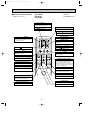
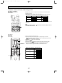
SPLIT-TYPE,AIR CONDITIONERS
No. OC129
REVISED EDITION-A
TECHNICAL & SERVICE MANUAL
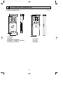
Series PK Wall Mounted
Indoor unit
[ Model names ]
[ Service Ref. ]
1997, 1999, 2001
PK-2.5FLA
1997
1999
PK-1.6FLA3
PK-2FLA3
PK-2.5FLA2
PK-3FLA
PK-3FLA2
PK-4FLSA
PK-4FLSA2
PK-1.6FLA
PK-2FLA
PK-3FLA3
2001
PK-2.5FLA3
PK-2.5FLA4
PK-3FLA4
PK-3FLA5
PK-4FLSA3
PK-4FLSA4
CONTENTS
Indoor unit
˚C
AM
PM
AM
PM
NOT AVAILABLE
ON / OFF
TEMP
PK-1.6FLA3
PK-2.5FLA4
PK-2FLA3
PK-3FLA5
PK-2.5FLA2/3
PK-4FLSA4
PK-3FLA2/3/4
PK-4FLSA2/3
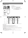
REMOTE CONTROLLER
• PK-2.5FLA3, PK-2.5FLA4, PK-3FLA3, PK-3FLA4, PK-3FLA5,
PK-4FLA3 and PK-4FLA4 are added in REVISED EDITION-A.
• Please void OC129 and OC200.
• This manual does not cover outdoor units. When servicing
them, please refer to the service manual No.OC127 REVISED
EDITION-A, OC187, OC217 REVISED EDITION-A and this
manual in a set.
1. TECHNICAL CHANGES ·······························3
2. COMBINATION OF INDOOR
AND OUTDOOR UNITS ··············3
3. PART NAMES AND FUNCTIONS ················3
4. SPECIFICATIONS ·········································6
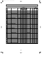
5. DATA ···························································13
6. OUTLINES AND DIMENSIONS ··················16
7. WIRING DIAGRAM ·····································20
8. REFRIGERANT SYSTEM DIAGRAM···············22
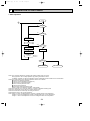
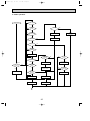
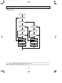
9. OPERATION FLOW-CHART ······················24
10. MICROPROCESSOR CONTROL ···············27
11. TROUBLESHOOTING·································36
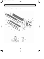
12. DISASSEMBLY PROCEDURE ···················39
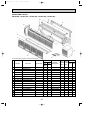
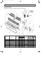
13. PARTS LIST ················································42
14. OPTIONAL PARTS ·····································54
OC129A-1.qxp
01.10.1 7:33 PM
Page 2
OC129A-1.qxp
01.10.1 7:33 PM
1
Page 3
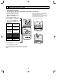
TECHNICAL CHANGES
PK-3FLA2 ➔ PK-3FLA3
PK-2.5FLA3 ➔ PK-2.5FLA4
PK-3FLA4 ➔ PK-3FLA5
PK-4FLSA3 ➔ PK-4FLSA4
● Outdoor units has changed.
● The parts No. of REMOTE CONTROLLER has changed.
(The following parts numbers are interchangeable.)
PK-2.5FLA2 ➔ PK-2.5FLA3
PK-3FLA3 ➔ PK-3FLA4
PK-4FLSA2 ➔ PK-4FLSA3
●
●
●
●
NOSE has changed by changing its shape.
UNDER PLATE has changed.
BOX ASSEMBLY has changed by changing its shape.
DRAIN PAN has changed by changing its shape.
˚C
AM
PM
AM
PM
NOT AVAILABLE
ON / OFF
TEMP
[ T7W 570 200 ]
2
COMBINATION OF INDOOR AND OUTDOOR UNITS
Indoor unit
PU-1.6
PU-2
PU-2.5
PU-3
PU-4
PU-3
PU-3
VLJSA2 VJA2 NJA1 VJA2 NJA1 VJA2 YJA2 YJA3 NJA1 VLJSA2 YJSA2 YJSA3 TJSA2 VJC YJC VJB YJB
—
—
—
—
—
—
—
—
—
—
—
—
—
—
—
—
—
—
—
—
—
—
—
—
—
—
—
—
—
—
—
—
—
—
—
—
—
—
—
—
—
—
—
—
—
—
—
—
—
—
—
—
—
—
—
—
PK-2FLA3
—
PK-2.5FLA2
PK-2.5FLA3
PK-2.5FLA4
—
—
—
PK-3FLA2
—
—
—
—
—
—
—
—
—
—
—
—
—
—
—
—
—
—
—
—
—
PK-3FLA3
PK-3FLA4
PK-3FLA5
PK-4FLSA2
PK-4FLSA3
PK-4FLSA4
Outdoor unit Outdoor unit
(OC187) (OC217
REVISED EDITION-A)
Outdoor unit
(OC127 REVISED EDITION-A)
PK-1.6FLA3
3
[ T7W E06 714 ]
—
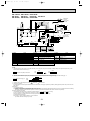
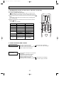
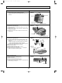
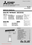
PART NAMES AND FUNCTIONS
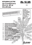
● Indoor Unit
Air intake
Room air is suctioned
in here.
Filter
Air intake grille
(Removes dust and dirt from the intake air.)
Guide vane
Swing louvers
Air flow can be changed to horizontally
by moving the Guide vane to the left or
right.
Disperses airflow up and
down as well as adjusts the
angle of air flow direction.
Air outlet
Air outlet
3
OC129A-1.qxp
01.10.1 7:33 PM
Page 4
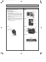
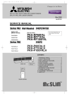
●Remote controller
● When cover is closed.
display
PK-1.6FLA3
PK-2FLA3
PK-2.5FLA2, PK-2.5FLA3
PK-3FLA2, PK-3FLA3, PK-3FLA4
PK-4FLSA2, PK-4FLSA3
Part No.
[ T7W 570 200 ]
display
SET TEMP. display indicates desired temperature set.
OPERATION MODE display
Operation mode display indicates which operation mode is in effect.
• CHECK • TEST RUN display
CHECK&TEST RUN display indicates that the
unit is being checked or test-run.
CLOCK display
˚C
display
DIsplays the current time.
AM
PM
“
AM
PM
Displays when batteries are dead.
”display
NOT AVAILABLE
Flashes when the current time is displayed.
display
ON / OFF
TIMER display
Displays when setting timer.
Displays when in timer operation or when setting timer.
display
➡
” display
Displays the order of timer operation.
TEMP
display
“
The vertical direction of airflow is indicated in
marks.
”“
” display
“
FAN SPEED display indicates which fan speed
has been selected.
▼
”“
▼
▼
Displays whether timer is on or off.
display
” display
Displays when the current time and the timer
time can be changed.
button
button
SET TEMPERATURE button sets any desired
room temperature.
Push to start operation. Push again to stop
operation.
SET CLOCK button
● When cover is open.
Button used to set the current time.
MODE SELECT button
MODE SELECT button is used to change
cooling. dry (dehumidify) and fan (ventilation)
operation modes.
”“
➡
“
Lights when signal is sent from the remote
controller to the indoor unit.
ON / OFF
TIMER CONTROL buttons
MODE
CLOCK
FAN
FAN SPEED SELECT button
VANE
STOP
START
HR
MIN.
FAN SPEED SELECT button selects low or
high fan speed.
STOP (OFF timer): when this switch is set,
the air conditioner will be automatically
stopped at the preset time.
START (ON timer): when this switch is set, the
air conditioner will be automatically started at
the preset time.
VANE CONTROL button
HR. and MIN.buttons
VANE CONTROL button regulates the vertical
distribution of airflow.
Buttons used to set the “hour and minute” of
the current time and timer time.
4
OC129A-1.qxp
01.10.1 7:33 PM
Page 5
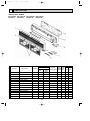
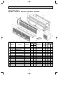
●Wireless remote controller
● When cover is open.
PK-2.5FLA4
PK-3FLA5
PK-4FLSA4
Part No.
[ T7W E06 714 ]
CHECK TEST RUN display
CHECK&TEST RUN display indicates that
the unit is being checked or test-run.
MODEL SELECT display
display
Blinks when model is selected.
Lights up while transmission to the indoor
unit is mode using switches.
display
SET TEMP. display indicates desired temperature set.
CLOCK display
display
Displays the current time.
OPERATION MODE display
Operation mode display indicates which operation mode is in effect.
TIMER display
CHECK TEST RUN
MODEL SELECT
˚C
AMPM
Displays when in timer operation or when
setting timer.
“
AMPM
NOT AVAILABLE
display
The vertical direction of air flow is indicated.
ON/OFF
“
TEMP
”“
” display
Displays the order of timer operation.
”“
” display
Displays whether timer is on or off.
display
button
FAN SPEED display indicates which fan
speed has been selected.
FAN
AUTO STOP
VANE
AUTO START
SET TEMPERATURE button sets any desired
room temperature.
ON/OFF button
The unit is turned ON and OFF alternately
each time the button is pressed.
MODE
CHECK LOUVER
h
FAN SPEED SELECT button
Used to change the fan speed.
MODE SELECT button
TEST RUN
SET
min
RESET
Used to switch the operation mode between
cooling, drying, fan.
TIMER CONTROL buttons
AUTO STOP (OFF timer): when this switch
is set, the air conditioner will be automatically stopped at the preset time.
AUTO START (ON timer): when this switch
is set, the air conditioner will be automatically started at the preset time.
CLOCK
h and min buttons
Buttons used to set the “hour and minute” of
the current time and timer settings.
LOUVER button
CHECK-TEST RUN button
This switch the horizontal fan motion ON
and OFF.
Only press this button to perform an inspection check or test operation.
Do not use it for normal operation.
(Not available for this model.)
CLOCK button
VANE CONTROL button
RESET button
Used to change the air flow direction.
SET button
5
OC129A-1.qxp
01.10.1 7:33 PM
4
Page 6
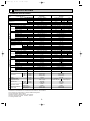
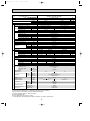
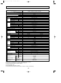
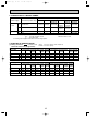
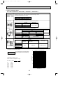
SPECIFICATIONS
1. STANDARD SPECIFICATION
Service Ref.
Item
Indoor, Outdoor D.B./W.B.°C
Condition
Capacity w1
Btu/h
W
kW
REFRIGERANT PIPING
OUTDOOR UNIT
INDOOR UNIT
Total input w1
Service Ref.
Power supply(phase, cycle,voltage)
Input
kW
Running current (Power factor)
A (%)
Starting current
A
External finish
Heat exchanger
Fan(drive) o No.
Fan motor output
kW
Airflow (Low-High)
m3/min(CFM)
Pa(mmAq)
External static pressure
kW
Booster heater
Operation control & Thermostat
dB
Noise level (Low-High) w2
mm(in.)
Cond. drain conn. O.D.
W
mm(in.)
D
mm(in.)
Dimensions
H
mm(in.)
kg(lbs)
Weight
Service Ref.
Power supply (phase, cycle, voltage)
kW
Input
A(%)
Running current (Power factor)
A
Starting current
External finish
Refrigerant control
Compressor
Model
kW
Motor output
Starter type
Protection devices
Heat exchanger
Fan(drive) o No.
kW
Fan motor output
m3/min(CFM)
Airflow
Defrost method
dB
Noise level w2
mm(in.)
W
mm(in.)
Dimensions
D
mm(in.)
H
kg(lbs)
Weight
W
Crankcase heater
kg(lbs)
Refrigerant Charge
mm(in.)
Liquid
Pipe size O.D.
mm(in.)
Gas
Indoor side
Connection method
Outdoor side
Between the indoor &
Height difference
outdoor units
Piping length
w1
w2
w3
w4
w5
w6
w7
PK-1.6FLA3
PK-2FLA3
27/19.0°C, 35/24°C
w6
27/19.0°C, 35/24°C
Cooling (JIS B8616)
w7
Cooling (JIS B8616)
19,000
19,100
16,000
13,300
5,450
5,600
4,600
3,900
2.54
2.52/2.56
3.06
1.49/1.59
PK-2FLA3
PK-1.6FLA3
Single, 50Hz, 220/240V
Single, 50Hz, 220/240V Single, 60Hz, 220V
0.07
0.08
0.09
0.32(99/91)
0.37(98/90)
0.42(97)
0.5
0.5
0.4
0.4
Munsell 3.4Y 7.7/0.8(White)
Munsell 3.4Y 7.7/0.8(White)
Plate fin coil
Plate fin coil
Line flow (direct) o 1
Line flow (direct) o 1
0.030
0.030
10-13 (353-459)
10-14 (353-459)
0 (direct blow)
0 (direct blow)
—
—
Wireless remote controller & Built-in
Wireless remote controller & Built-in
36 - 43
38 - 45
20 (13/16)
20 (13/16)
1,250 (49-3/16)
1,250 (49-3/16)
200 (7-7/8)
200 (7-7/8)
300 (11-13/16)
300 (11-13/16)
17 (37)
17 (37)
PU-1.6VLJA2
PU-2VJA2
PU-2NJA1
Single, 50Hz, 220/240V
Single, 50Hz, 220/240V Single, 60Hz, 220V
2.45
2.97
1.42 / 1.52
2.44 / 2.48
11.4(98) 13.6(99)
6.7 / 6.9 (97/92)
11.3 / 10.8(98/96)
54
54
30 /33
48 / 52
Munsell 5Y 7/1
Munsell 5Y 7/1
Capillary tube
Capillary tube
Hermetic
Hermetic
RH247VFC
NHJ41VMD
NHJ33NBD
1.2
2.0
1.5
Line start
Line start
w4
Inner thermostat, HP/LP switch
Plate fin coil
Plate fin coil
Propeller (direct ) o 1
Propeller (direct) o 1
0.065
0.065
45 (1588)
45 (1588)
—
—
49
49
50
870 (34-1/4)
870 (34-1/4)
295 (11-5/8)
295 (11-5/8)
650 (25-5/8)
650 (25-5/8)
45 (99)
60 (132)
—
32 / 38
—
R-22 1.78 (3.9)
R-22 1.9 (4.2)
R-22 1.3 (2.9)
9.52 (3/8)
9.52 (3/8)
15.88 (5/8)
15.88 (5/8)
Flared
Flared
Flared
Flared
w3 Max. 15m
w3 Max. 20m
w3 Max. 20m
w3 Max. 30m
Refrigerant piping length (one way) : 5m (16ft)
Noise level is measured in an unacoustic room based on JIS conditions.
Up to 20m it is unnecessary to charge additional refrigerant.
Inner thermostat, HP/LP switch.
Motor protector, Thermal switch, HP/LP switch.
Indoor, Outdoor D.B./W.B. : 29/19°C, 46/24°C
Cooling SSA385, 386
6
OC129A-1.qxp
01.10.1 7:33 PM
Page 7
Service Ref.
PK-2.5FLA2 PK-2.5FLA3 PK-2.5FLA4
Item
27/19.0°C, 35/24°C
Cooling (JIS B8616)
Indoor, Outdoor D.B./W.B.°C
Condition
Capacity w1
Btu/h
W
kW
OUTDOOR UNIT
INDOOR UNIT
Total input w1
Service Ref.
Power supply(phase, cycle,voltage)
Input
kW
Running current (Power factor)
A(%)
Starting current
A
External finish
Heat exchanger
Fan(drive) o No.
kW
Fan motor output
m3/min(CFM)
Airflow (Low-High)
Pa(mmAq)
External static pressure
kW
Booster heater
Operation control & Thermostat
dB
Noise level (Low-High) w2
mm(in.)
Cond. drain conn. O.D.
W
mm(in.)
D
mm(in.)
Dimensions
H
mm(in.)
kg(lbs)
Weight
Service Ref.
Power supply (phase, cycle, voltage)
kW
Input
A(%)
Running current (Power factor)
A
Starting current
External finish
Refrigerant control
Compressor
Model
kW
Motor output
Starter type
Protection devices
Heat exchanger
Fan(drive) o No.
kW
Fan motor output
m3/min(CFM)
Airflow
Defrost method
dB
Noise level w2
mm(in.)
W
mm(in.)
Dimensions
D
mm(in.)
H
kg(lbs)
Weight
W
Crankcase heater
kg(lbs)
Refrigerant Charge
mm(in.)
Liquid
Pipe size O.D.
mm(in.)
Gas
Indoor side
Connection method
Outdoor side
Between the indoor &
Height difference
outdoor units
Piping length
24,400
23,900
7,150
7,000
3.01
2.56 / 2.62
PK-2.5FLA2 PK-2.5FLA3 PK-2.5FLA4
Single, 60Hz, 220V
Single, 50Hz, 220/240V
0.095
0.095 / 0.095
0.44 (98)
0.44 / 0.44 (98/90)
0.7
0.7 / 0.8
Munsell 3.4Y 7.7/0.8(White)
Plate fin coil
Line flow (direct) o 2
0.04
15 - 20(530-706)
0 (direct blow)
—
Wireless remote controller & Built-in
39 - 45
20 (13/16)
1,400 (55-1/8)
235 (9-1/4)
340 (13-3/8)
24 (53)
PU-2.5NJA1
PU-2.5VJA2
Single, 60Hz, 220V
Single, 50Hz, 220/240V
2.91
2.46 / 2.52
13.4 (99)
11.4 / 10.7 (98/98)
58
45 / 49
Munsell 5Y 7/1
Capillary tube
Hermetic
NHJ41VMD
2.0
Line start
Inner thermostat, HP/LP switch
Plate fin coil
Propeller (direct) o 1
0.085
50 (1765)
—
52
53
870 (34-1/4)
295 (+24) (11-5/8 (add 1))
850 (33-7/16)
71 (157)
32 / 38
R-22 2.4 (5.3)
REFRIGERANT PIPING
w1
w2
w3
w4
w5
NHJ38NBD
1.7
—
R-22 2.4 (5.3)
9.52 (3/8)
15.88 (5/8)
Flared
Flared
w3 Max. 20m
w3 Max. 30m
Refrigerant piping length (one way) : 5m (16ft)
Noise level is measured in an unacoustic room based on JIS conditions.
Up to 20m it is unnecessary to charge additional refrigerant.
Indoor, Outdoor D.B./W.B. : 29/19°C, 46/24°C.
Cooling SSA385, 386
7
w4
w5
22,700
6,650
3.54
3.44
15.8(99)
58
OC129A-1.qxp
01.10.1 7:33 PM
Page 8
Service Ref.
PK-3FLA2
Item
Indoor, Outdoor D.B./W.B.°C
27/19.0°C, 35/24°C
Cooling (JIS B8616)
Condition
Capacity w1
Btu/h
W
kW
24,600
7,200
27,300
8,000
3.54
REFRIGERANT PIPING
OUTDOOR UNIT
INDOOR UNIT
3.28 / 3.30
3.28 / 3.30
Total input w1
PK-3FLA2
Service Ref.
Single, 50Hz, 220/240V
Single, 60Hz, 220V
Power supply(phase, cycle,voltage)
0.095 / 0.095
0.095
kW
Input
0.44 / 0.44 (98/90)
0.44 (98)
A(%)
Running current (Power factor)
0.7 / 0.8
0.7
A
Starting current
External finish
Munsell 3.4Y 7.7/0.8(White)
Heat exchanger
Plate fin coil
Fan(drive) o No.
Line flow (direct) o 2
kW
Fan motor output
0.04
m3/min(CFM)
Airflow (Low-High)
15 - 20 (530-706)
Pa(mmAq)
External static pressure
0 (direct blow)
kW
Booster heater
—
Operation control & Thermostat
Wireless remote controller & Built-in
dB
Noise level (Low-High) w2
39 - 45
mm(in.)
Cond. drain conn. O.D.
20 (13/16)
W
mm(in.)
1,400 (55-1/8)
D
mm(in.)
Dimensions
235 (9-1/4)
H
mm(in.)
340 (13-3/8)
kg(lbs)
Weight
24 (53)
PU-3YJA2 PU-3YJA3
PU-3NJA1
PU-3VJA2
Service Ref.
Single, 60Hz, 220V
Single, 50Hz, 220/240V Three, 50Hz, 380/415V
Power supply (phase, cycle, voltage)
3.44
3.18 / 3.20
3.18 / 3.20
kW
Input
17.6(89)
15.1/13.9(96/96)
5.7/5.3(85/84)
A(%)
Running current (Power factor)
80
68 / 68
36 / 36
A
Starting current
Munsell 5Y 7/1
External finish
Capillary tube
Refrigerant control
Hermetic
Compressor
Model
NHJ52YDA NHJ52YDE
NHJ47NAD
NHJ52VND
kW
Motor output
2.2
2.2
2.2
Line start
Starter type
w6
w7
w6
Protection devices
Plate fin coil
Heat exchanger
Propeller (direct) o 1
Fan(drive) o No.
0.085
kW
Fan motor output
50 (1765)
m3/min(CFM)
Airflow
—
Defrost method
53
53
dB
Noise level w2
870 (34-1/4)
mm(in.)
W
295 (+24) (11-5/8 (add 1))
mm(in.)
Dimensions
D
850 (33-7/16)
mm(in.)
H
73 (161)
kg(lbs)
Weight
W
Crankcase heater
32 / 38
32 / 38
38
kg(lbs)
Refrigerant Charge
R-22 3.08 (6.8)
R-22 2.88 (6.3)
R-22 3.5 (7.7)
mm(in.)
Liquid
9.52 (3/8)
Pipe size O.D.
mm(in.)
Gas
15.88 (5/8)
Indoor side
Flared
Connection method
Outdoor side
Flared
Between the indoor &
Height difference
w3 Max. 20m
outdoor units
Piping length
w3 Max. 30m
w4
w5
23,500
6,900
4.19
w1 Refrigerant piping length (one way) : 5m (16ft)
w2 Noise level is measured in an unacoustic room based on JIS conditions.
w3 Up to 20m it is unnecessary to charge additional refrigerant.
w4 Indoor, Outdoor D.B./W.B. : 29/19°C, 46/24°C
w5 Cooling SSA385, 386
w6 Inner thermostat, HP switch, LP switch.
w7 Thermal switch, Reversed-phase protector, HP switch, LP switch, Thermal relay.
8
4.09
20.9(89)
80
OC129A-1.qxp
01.10.1 7:33 PM
Page 9
Service Ref.
PK-3FLA3 PK-3FLA4 PK-3FLA5
Item
Indoor, Outdoor D.B./W.B.°C
27/19°C , 35/24°C
Cooling (JIS B8616)
Condition
27,300
8,000
3.28 / 3.30
3.28 / 3.30
3.54
Total input w1
PK-3FLA3 PK-3FLA4 PK-3FLA5
Service Ref.
Single, 50Hz, 220/240V
Single, 60Hz, 220V
Power supply(phase, cycle,voltage)
0.095 / 0.095
0.095
Input
kW
0.44 / 0.44 (98/90)
0.44 (98)
Running current (Power factor)
A(%)
0.7 / 0.8
0.7
Starting current
A
External finish
Munsell 3.4Y 7.7/0.8(White)
Heat exchanger
Plate fin coil
Fan(drive) o No.
Line flow (direct) o 2
Fan motor output
kW
0.04
Airflow (Low-High)
m3/min(CFM)
15 - 20 (530-706)
Pa,mmAq
External static pressure
0 (direct blow)
kW
Booster heater
—
Operation control & Thermostat
Wireless remote controller & Built-in
dB
Noise level (Low-High) w2
39 - 45
mm(in.)
Unit drain pipe O.D.
20 (13/16)
W
mm(in.)
1,400 (55-1/8)
D
mm(in.)
Dimensions
235 (9-1/4)
H
mm(in.)
340 (13-3/8)
kg(lbs)
Weight
24 (53)
PU-3YJC
PU-3NJA1
PU-3VJC
Service Ref.
Single, 50Hz, 220/240V Three, 50Hz, 380/415V
Single, 60Hz, 220V
Power supply (phase, cycle, voltage)
3.44
3.18 / 3.20
3.18 / 3.20
kW
Input
17.6(89)
15.1/13.9(96/96)
5.7/5.3(85/84)
A(%)
Running current (Power factor)
80
54 / 58
34 / 37
A
Starting current
Munsell 5Y 7/1
External finish
Capillary tube
Refrigerant control
Hermetic
Compressor
Model
NHJ47NAD
NH52VND
NH52YDE
kW
Motor output
2.2
2.2
2.4
Line start
Starter type
w6
w7
w6
Protection devices
Plate fin coil
Heat exchanger
Propeller (direct) o 1
Fan(drive) o No.
0.085
kW
Fan motor output
50 (1765)
m3/min(CFM)
Airflow
—
Defrost method
52
53
dB
Noise level w2
870 (34-1/4)
mm(in.)
W
295 (+24) (11-5/8 (add 1))
mm(in.)
Dimensions
D
850 (33-7/16)
mm(in.)
H
73 (161)
kg(lbs)
Weight
W
Crankcase heater
32 / 38
32 / 38
38
R-22 2.8(6.2)
kg(lbs)
Refrigerant Charge
R-22 3.5 (7.7)
mm(in.)
Liquid
9.52 (3/8)
Pipe size O.D.
mm(in.)
Gas
15.88 (5/8)
Indoor side
Flared
Connection method
Outdoor side
Flared
Between the indoor &
Height difference
w3 Max. 20m
outdoor units
Piping length
w3 Max. 30m
27,000
7,900
Btu/h
W
kW
REFRIGERANT PIPING
OUTDOOR UNIT
INDOOR UNIT
Capacity w1
w4
w5
23,500
6,900
4.19
w1 Refrigerant piping length (one way) : 5m (16ft)
w2 Noise level is measured in an unacoustic room based on JIS conditions.
w3 Up to 20m it is unnecessary to charge additional refrigerant.
w4 Indoor, Outdoor D.B./W.B. : 29/19°C, 46/24°C
w5 Cooling SSA385, 386
w6 Inner thermostat, HP switch, LP switch.
w7 Thermal switch, Reversed-phase protector, HP switch, LP switch, Thermal relay.
9
4.09
20.9(89)
80
OC129A-1.qxp
01.10.1 7:33 PM
Page 10
Service Ref.
Item
Indoor, Outdoor D.B./W.B.°C
Condition
Capacity w1
Btu/h
W
kW
27/19°C , 35/24°C
Cooling (JIS B8616)
25,600
7,500
2.75
PK-3FLA2 PK-3FLA3 PK-3FLA4 PK-3FLA5
Single, 50Hz, 220V
0.095
0.44 (98)
0.7
Munsell 3.4Y 7.7/0.8(White)
Plate fin coil
Line flow (direct) o 2
0.04
15 - 20 (530-706)
0 (direct blow)
—
Wireless remote controller & Built-in
39 - 45
20 (13/16)
1,400 (55-1/8)
235 (9-1/4)
340 (13-3/8)
24 (53)
PU-3YJB
PU-3VJB
Single, 50Hz, 220V
Three, 50Hz, 380V
2.65
2.65
12.4(97)
4.2(97)
54
34
Munsell 5Y 7/1
Capillary tube
Hermetic
NH47VNHT
NH47YDNT
2.2
2.2
Line start
w6
w7
Plate fin coil
Propeller (direct) o 1
0.085
50 (1765)
—
52
870 (34-1/4)
295 (+24) (11-5/8 (add 1))
850 (33-7/16)
73 (161)
32
32
R-22 3.0(6.6)
9.52 (3/8)
15.88 (5/8)
Flared
Flared
w3 Max. 20m
w3 Max. 30m
REFRIGERANT PIPING
OUTDOOR UNIT
INDOOR UNIT
Total input w1
Service Ref.
Power supply(phase, cycle,voltage)
Input
kW
Running current (Power factor)
A(%)
Starting current
A
External finish
Heat exchanger
Fan(drive) o No.
kW
Fan motor output
m3/min(CFM)
Airflow (Low-High)
Pa,mmAq
External static pressure
kW
Booster heater
Operation control & Thermostat
dB
Noise level (Low-High) w2
mm(in.)
Unit drain pipe O.D.
W
mm(in.)
D
mm(in.)
Dimensions
H
mm(in.)
kg(lbs)
Weight
Service Ref.
Power supply (phase, cycle, voltage)
kW
Input
A(%)
Running current /Power factor
A
Starting current
External finish
Refrigerant control
Compressor
Model
kW
Motor output
Starter type
Protection devices
Heat exchanger
Fan(drive) o No.
kW
Fan motor output
m3/min(CFM)
Airflow
Defrost method
dB
Noise level w2
mm(in.)
W
mm(in.)
Dimensions
D
mm(in.)
H
kg(lbs)
Weight
W
Crankcase heater
kg(lbs)
Refrigerant Charge
mm(in.)
Liquid
Pipe size O.D.
mm(in.)
Gas
Indoor side
Connection method
Outdoor side
Between the indoor &
Height difference
outdoor units
Piping length
PK-3FLA2 PK-3FLA3 PK-3FLA4 PK-3FLA5
w1 Refrigerant piping length (one way) : 5m (16ft)
w2 Noise level is measured in an unacoustic room based on JIS conditions.
w3 Up to 20m it is unnecessary to charge additional refrigerant.
w4 Indoor, Outdoor D.B./W.B. : 29/19°C, 46/24°C
w5 Cooling SSA385, 386
w6 Inner thermostat, HP switch, LP switch.
w7 Thermal switch, Reversed-phase protector, HP switch, LP switch, Thermal relay.
10
OC129A-1.qxp
01.10.1 7:33 PM
Page 11
Service Ref.
PK-4FLSA2 PK-4FLSA3 PK-4FLSA4
Item
27/19.0°C, 35/24°C
Cooling (JIS B8616)
Indoor, Outdoor DB/WB°C
Condition
37,500
11,000
3.46 / 3.63
3.40 / 3.47
4.38
Total input w1
PK-4FLSA2 PK-4FLSA3 PK-4FLSA4
Service Ref.
Single, 50Hz, 220/240V
Single, 60Hz, 220V
Power supply(phase, cycle,voltage)
0.114 / 0.114
0.114
kW
Input
0.53 / 0.53 (98/90)
0.53 (98)
A(%)
Running current (Power factor)
0.8 / 0.9
0.8
A
Starting current
Munsell 3.4Y 7.7/0.8(White)
External finish
Plate fin coil
Heat exchanger
Line flow (direct) o 2
Fan(drive) o No.
0.07
kW
Fan motor output
22 - 28 (777 - 989)
m3/min(CFM)
Airflow (Low-High)
0 (direct blow)
Pa(mmAq)
External static pressure
—
kW
Booster heater
Wireless remote controller & Built-in
Operation control & Thermostat
41 - 46
dB
Noise level (Low-High) w2
20 (13/16)
mm(in.)
Cond. drain conn. O.D.
1,680 (66-1/8)
W
mm(in.)
235 (9-1/4)
D
mm(in.)
Dimensions
340 (13-3/8)
H
mm(in.)
28 (62)
kg(lbs)
Weight
PU-4YJSA2 PU-4YJSA3
PU-4VLJSA2
PU-4TJSA2
Service Ref.
Single, 50Hz, 220/240V Three, 50Hz, 380/415V
3, 60Hz, 220V
Power supply (phase, cycle, voltage)
4.27
3.35 / 3.52
3.29 / 3.36
kW
Input
12.2 (92)
16.9 / 16.3 (90/90) 5.7 / 5.5 (87/85)
A(%)
Running current (Power factor)
69
79 / 79
38 / 38
A
Starting current
Munsell 5Y 7/1
External finish
Capillary tube
Refrigerant control
Hermetic
Compressor
NH56VND
NHJ56YDA NHJ56YDE
NHJ56TKA
Model
2.7
2.7
2.7
kW
Motor output
Line start
Starter type
w6
w7
w7
Protection devices
Plate fin coil
Heat exchanger
Propeller (direct) o 2
Fan(drive) o No.
0.065 + 0.065
kW
Fan motor output
95 (3352)
m3/min(CFM)
Airflow
—
Defrost method
54
55
55
dB
Noise level w2
mm(in.)
W
870 (34-1/4)
mm(in.)
Dimensions
D
295 (+24) (11-5/8 (add 1))
mm(in.)
H
1258 (49-1/2)
kg(lbs)
Weight
94 (207)
W
Crankcase heater
32 / 38
38
32 / 38
kg(lbs)
Refrigerant Charge
R-22 3.8 (8.4)
R-22 4.6 (10.1)
R-22 4.6 (10.1)
9.52 (3/8)
mm(in.)
Liquid
Pipe size O.D.
19.05 (4/3)
mm(in.)
Gas
Flared
Indoor side
Connection method
Flared
Outdoor side
w3 Max. 30m
Between the indoor &
Height difference
w3 Max. 40m
outdoor units
Piping length
33,400
9,800
Btu/h
W
kW
REFRIGERANT PIPING
OUTDOOR UNIT
INDOOR UNIT
Capacity w1
w4
w5
33,800
9,900
5.08
w1 Refrigerant piping length (one way) : 5m (16ft)
w2 Noise level is measured in an unacoustic room based on JIS conditions.
w3 Up to 20m it is unnecessary to charge additional refrigerant.
w4 Indoor, Outdoor D.B./W.B. : 29/19°C, 46/24°C
w5 Cooling SSA385, 386
w6 Inner thermostat, HP switch, LP switch.
w7 Thermal switch, Reversed-phase protector, HP switch, LP switch, Thermal relay.
11
4.97
14.0(93)
69
OC129A-1.qxp
01.10.1 7:33 PM
Page 12
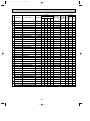
2. POWER SUPPLY & MODEL NAMES
Power supply
1ph
50Hz
60Hz
Service Ref. (Outdoor unit)
Service Ref. (Indoor unit) PK-1.6FLA3 PK-2FLA3 PK-2.5FLA2 PK-3FLA2 PK-3FLA3
PK-2.5FLA3
PK-3FLA4
PK-2.5FLA4
PK-3FLA5
PU-3VJA2 PU-3VJC
PU-1.6VLJA2 PU-2VJA2 PU-2.5VJA2
220,230,240V
PU-3VJB
PU-3VJB
3ph
380/220,400/230,415/240V
—
—
1ph
220V
—
PU-2NJA1
3ph
220V
—
—
—
(1) Rating conditions
JIS B8615, 8616
Series PK Indoor Unit (Single Phase)
PU-3YJC
PU-3YJB
PU-3YJB
PU-2.5NJA1 PU-3NJA1
—
Notes : 1. Power supply key N …… 1ph, 220V, 60Hz
V(L) … 1ph, 220, 230 240V, 50Hz
T …… 3ph, 220V, 60Hz
2. Primary power supplies for all indoor units are single-phase.
3. ELECTRICAL SPECIFICATION
PU-3YJA3
—
PK-4FLSA2
PK-4FLSA3
PK-4FLSA4
PU-4VLJSA2
PU-4YJSA3
PU-3NJA1
—
—
PU-4TJSA2
Y … 3ph, 380/220, 400/230,
415/240V, 50Hz, 4 wires
Indoor : D.B. 27°C (80°F), W.B. 19°C(66°F)
Outdoor : D.B. 35°C (95°F)
Power supply (1 Phase)
Service Ref.
Current
Input
V : 220V 50Hz
V : 230V 50Hz
PK-1.6FLA3 PK-2FLA3 PK-2.5FLA2 PK-3FLA2 PK-3FLA3 PK-4FLSA2 PK-1.6FLA3 PK-2FLA3 PK-2.5FLA2 PK-3FLA2 PK-3FLA3 PK-4FLSA2
PK-2.5FLA3
PK-2.5FLA3
PK-3FLA4 PK-4FLSA3
PK-3FLA4 PK-4FLSA3
PK-2.5FLA4
PK-2.5FLA4
PK-3FLA5 PK-4FLSA4
PK-3FLA5 PK-4FLSA4
A
0.32
0.37
0.44
0.44
0.44
0.53
0.32
0.37
0.44
0.44
0.44
0.53
kW
Starting current A
Outdoor unit
0.07
0.08
0.095
0.095
0.095
0.114
0.07
0.08
0.095
0.095
0.095
0.114
0.4
0.4
0.7
0.7
0.7
0.8
0.4
0.4
0.8
0.8
0.8
0.8
PU-1.6
PU-2
PU-2.5
PU-3
PU-3
PU-4
PU-1.6
PU-2
PU-2.5
PU-3
PU-3
PU-4
Power supply (1 Phase)
Service Ref.
Current
Input
V : 240V 50Hz
N : 220V 50Hz
PK-1.6FLA3 PK-2FLA3 PK-2.5FLA2 PK-3FLA2 PK-3FLA3 PK-4FLSA2 PK-2FLA3 PK-2.5FLA2 PK-3FLA2 PK-3FLA3 PK-4FLSA2
PK-2.5FLA3
PK-2.5FLA3
PK-3FLA4 PK-4FLSA3
PK-3FLA4 PK-4FLSA3
PK-2.5FLA4
PK-2.5FLA4
PK-3FLA5 PK-4FLSA4
PK-3FLA5 PK-4FLSA4
A
0.32
0.37
0.44
0.44
0.44
0.53
0.43
0.44
0.44
0.44
0.53
kW
Starting current A
Outdoor unit
0.07
0.08
0.095
0.095
0.095
0.114
0.09
0.095
0.095
0.095
0.114
0.4
0.4
0.8
0.8
0.8
0.8
0.5
0.7
0.7
0.7
0.8
PU-1.6
PU-2
PU-2.5
PU-3
PU-3
PU-4
PU-2
PU-2.5
PU-3
PU-3
PU-4
12
OC129A-1.qxp
01.10.1 7:33 PM
5
Page 13
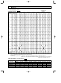
DATA
1. PERFORMANS DATA
W Outdoor unit
PU-3JB
COOLING CAPACITY 50Hz
Service Ref.
Temperature
Outdoor D.B.
Indoor W.B.
16˚C
(60.8˚ F)
18˚C
(64.4˚ F)
21˚C
19˚C
(66.2˚ F)
19.4˚C
(67˚ F)
(69.8˚ F)
20˚C
(68˚ F)
22˚C
(71.6˚ F)
16˚C
(60.8˚ F)
18˚C
(64.4˚ F)
25˚C
19˚C
(66.2˚ F)
19.4˚C
(67˚ F)
(77˚ F)
20˚C
(68˚ F)
22˚C
(71.6˚ F)
16˚C
(60.8˚ F)
18˚C
(64.4˚ F)
30˚C
19˚C
(66.2˚ F)
19.4˚C
(67˚ F)
(86˚ F)
20˚C
(68˚ F)
22˚C
(71.6˚ F)
16˚C
(60.8˚ F)
18˚C
(64.4˚ F)
32.2˚C
19˚C
(66.2˚ F)
19.4˚C
(67˚ F)
(90˚ F)
20˚C
(68˚ F)
22˚C
(71.6˚ F)
16˚C
(60.8˚ F)
18˚C
(64.4˚ F)
35˚C
19˚C
(66.2˚ F)
19.4˚C
(67˚ F)
(95˚ F)
20˚C
(68˚ F)
22˚C
(71.6˚ F)
16˚C
(60.8˚ F)
18˚C
(64.4˚ F)
40˚C
19˚C
(66.2˚ F)
19.4˚C
(67˚ F)
(104˚ F)
20˚C
(68˚ F)
22˚C
(71.6˚ F)
16˚C
(60.8˚ F)
18˚C
(64.4˚ F)
40.6˚C
19˚C
(66.2˚ F)
19.4˚C
(67˚ F)
(105˚ F)
20˚C
(68˚ F)
22˚C
(71.6˚ F)
16˚C
(60.8˚ F)
18˚C
(64.4˚ F)
45˚C
19˚C
(66.2˚ F)
19.4˚C
(67˚ F)
(113˚ F)
20˚C
(68˚ F)
22˚C
(71.6˚ F)
16˚C
(60.8˚ F)
18˚C
(64.4˚ F)
46˚C
19˚C
(66.2˚ F)
19.4˚C
(67˚ F)
(115˚ F)
20˚C
(68˚ F)
22˚C
(71.6˚ F)
16˚C
(60.8˚ F)
18˚C
(64.4˚ F)
50˚C
19˚C
(66.2˚ F)
19.4˚C
(67˚ F)
(69.8˚ F)
20˚C
(68˚ F)
22˚C
(71.6˚ F)
16˚C
(60.8˚ F)
18˚C
(64.4˚ F)
52˚C
19˚C
(66.2˚ F)
19.4˚C
(67˚ F)
(125.5˚ F)
20˚C
(68˚ F)
22˚C
(71.6˚ F)
Evaporator airflow (CMM)
Bypass factors
S.H.F. at rating conditions
PK-2FLA3
T.C.
C.F.
(T.I.)
5.6
0.81
6.0
0.82
6.2
0.83
6.2
0.83
6.4
0.84
6.7
0.86
5.5
0.84
5.9
0.85
6.0
0.86
6.1
0.86
6.2
0.87
6.6
0.89
5.3
0.90
5.6
0.92
5.8
0.93
5.9
0.93
6.0
0.94
6.4
0.96
5.2
0.93
5.5
0.95
5.7
0.96
5.8
0.97
5.9
0.97
6.3
0.99
5.1
0.96
5.4
0.99
5.6
1.00
5.7
1.00
5.8
1.01
6.2
1.04
4.9
1.03
5.2
1.06
5.4
1.07
5.4
1.08
5.5
1.08
5.9
1.11
4.8
1.04
5.2
1.06
5.3
1.08
5.4
1.08
5.5
1.09
5.9
1.12
4.6
1.10
4.9
1.12
5.1
1.14
5.2
1.15
5.3
1.16
5.7
1.20
4.6
1.11
4.9
1.14
5.1
1.15
5.1
1.16
5.2
1.17
5.6
1.21
4.4
1.16
4.7
1.19
4.9
1.21
4.9
1.22
5.0
1.23
5.4
1.28
4.3
1.19
4.6
1.22
4.7
1.24
4.8
1.25
4.9
1.26
5.3
1.31
14
0.16
0.73
PK-1.6FLA3
C.F.
T.C.
(T.I.)
3.9
0.81
4.2
0.82
4.3
0.83
4.4
0.83
4.4
0.84
4.7
0.86
3.8
0.84
4.1
0.85
4.2
0.86
4.3
0.86
4.3
0.87
4.6
0.89
3.7
0.90
3.9
0.92
4.1
0.93
4.1
0.93
4.2
0.94
4.5
0.96
3.6
0.93
3.9
0.95
4.0
0.96
4.0
0.97
4.1
0.97
4.4
0.99
3.5
0.96
3.8
0.99
3.9
1.00
4.0
1.00
4.0
1.01
4.3
1.04
3.4
1.03
3.6
1.06
3.7
1.07
3.8
1.08
3.9
1.08
4.1
1.11
3.4
1.04
3.6
1.06
3.7
1.08
3.8
1.08
3.8
1.09
4.1
1.12
3.2
1.10
3.4
1.12
3.6
1.14
3.6
1.15
3.7
1.16
3.9
1.20
3.2
1.11
3.4
1.14
3.5
1.15
3.6
1.16
3.6
1.17
3.9
1.21
13
0.18
0.81
PK-2.5FLA3/4
T.C.
C.F.
(T.I.)
7.0
0.81
7.5
0.82
7.7
0.83
7.8
0.83
7.9
0.84
8.4
0.86
6.9
0.84
7.3
0.85
7.6
0.86
7.7
0.86
7.8
0.87
8.3
0.89
6.6
0.90
7.1
0.92
7.3
0.93
7.4
0.93
7.5
0.94
8.0
0.96
6.5
0.93
6.9
0.95
7.2
0.96
7.3
0.97
7.4
0.97
7.9
0.99
6.3
0.96
6.8
0.99
7.0
1.00
7.1
1.00
7.2
1.01
7.7
1.04
6.1
1.03
6.5
1.06
6.7
1.07
6.8
1.08
6.9
1.08
7.4
1.11
6.0
1.04
6.4
1.06
6.7
1.08
6.8
1.08
6.9
1.09
7.4
1.12
5.8
1.10
6.2
1.12
6.4
1.14
6.5
1.15
6.6
1.16
7.1
1.20
5.7
1.11
6.1
1.14
6.3
1.15
6.4
1.16
6.5
1.17
7.0
1.21
5.5
1.16
5.9
1.19
6.1
1.21
6.2
1.22
6.3
1.23
6.7
1.28
5.3
1.19
5.7
1.22
5.9
1.24
6.0
1.25
6.1
1.26
6.6
1.31
20
0.11
0.81
PK-3FLA2
T.C.
C.F.
(T.I.)
7.2
0.81
7.7
0.82
7.9
0.83
8.0
0.83
8.2
0.84
8.7
0.86
7.1
0.84
7.5
0.85
7.8
0.86
7.9
0.86
8.0
0.87
8.5
0.89
6.8
0.90
7.3
0.92
7.5
0.93
7.6
0.93
7.7
0.94
8.2
0.96
6.7
0.93
7.1
0.95
7.4
0.96
7.5
0.97
7.6
0.97
8.1
0.99
6.5
0.96
7.0
0.99
7.2
1.00
7.3
1.00
7.4
1.01
7.9
1.04
6.2
1.03
6.7
1.06
6.9
1.07
7.0
1.08
7.1
1.08
7.6
1.11
6.2
1.04
6.6
1.06
6.9
1.08
6.9
1.08
7.1
1.09
7.6
1.12
5.9
1.10
6.4
1.12
6.6
1.14
6.7
1.15
6.8
1.16
7.3
1.20
5.9
1.11
6.3
1.14
6.5
1.15
6.6
1.16
6.7
1.17
7.2
1.21
5.6
1.16
6.0
1.19
6.2
1.21
6.3
1.22
6.5
1.23
6.9
1.28
5.5
1.19
5.9
1.22
6.1
1.24
6.2
1.25
6.3
1.26
6.8
1.31
20
0.12
0.76
PK-3FLA3/4/5
T.C.
C.F.
(T.I.)
0.81
7.9
0.82
8.4
0.83
8.7
0.83
8.8
0.84
9.0
0.86
9.5
0.84
7.8
0.85
8.3
0.86
8.5
0.86
8.6
0.87
8.8
0.89
9.4
0.90
7.5
0.92
8.0
0.93
8.2
0.93
8.3
0.94
8.5
0.96
9.0
0.93
7.3
0.95
7.8
0.96
8.1
0.97
8.2
0.97
8.3
0.99
8.9
0.96
7.2
0.99
7.6
1.00
7.9
1.00
8.0
1.01
8.2
1.04
8.7
1.03
6.8
1.06
7.3
1.07
7.6
1.08
7.7
1.08
7.8
1.11
8.3
1.04
6.8
1.06
7.3
1.08
7.5
1.08
7.6
1.09
7.8
1.12
8.3
1.10
6.5
1.12
7.0
1.14
7.2
1.15
7.3
1.16
7.5
1.20
8.0
1.11
6.4
1.14
6.9
1.15
7.1
1.16
7.2
1.17
7.4
1.21
7.9
1.16
6.2
1.19
6.6
1.21
6.9
1.22
6.9
1.23
7.1
1.28
7.6
1.19
6.0
1.22
6.5
1.24
6.7
1.25
6.8
1.26
6.9
1.31
7.4
20
0.12
0.73
PK-3FLA2/3/4/5 W
T.C.
C.F.
(T.I.)
0.81
7.5
0.82
8.0
0.83
8.3
0.83
8.4
0.84
8.5
0.86
9.0
0.84
7.4
0.85
7.8
0.86
8.1
0.86
8.2
0.87
8.4
0.89
8.9
0.90
7.1
0.92
7.6
0.93
7.8
0.93
7.9
0.94
8.1
0.96
8.6
0.93
7.0
0.95
7.4
0.96
7.7
0.97
7.8
0.97
7.9
0.99
8.4
0.96
6.8
0.99
7.3
1.00
7.5
1.00
7.6
1.01
7.7
1.04
8.3
1.03
6.5
1.06
6.9
1.07
7.2
1.08
7.3
1.08
7.4
1.11
7.9
1.04
6.5
1.06
6.9
1.08
7.1
1.08
7.2
1.09
7.4
1.12
7.9
1.10
6.2
1.12
6.6
1.14
6.8
1.15
6.9
1.16
7.1
1.20
7.6
1.11
6.1
1.14
6.5
1.15
6.8
1.16
6.9
1.17
7.0
1.21
7.5
20
0.12
0.75
PK-4FLSA2/3/4
T.C.
C.F.
(T.I.)
0.81
9.8
0.82
10.5
0.83
10.8
0.83
10.9
0.84
11.1
0.86
11.8
0.84
9.6
0.85
10.2
0.86
10.6
0.86
10.7
0.87
10.9
0.89
11.6
0.90
9.3
0.92
9.9
0.93
10.2
0.93
10.3
0.94
10.5
0.96
11.2
0.93
9.1
0.95
9.7
0.96
10.0
0.97
10.2
0.97
10.3
0.99
11.0
0.96
8.9
0.99
9.5
1.00
9.8
1.00
9.9
1.01
10.1
1.04
10.8
1.03
8.5
1.06
9.1
1.07
9.4
1.08
9.5
1.08
9.7
1.11
10.3
1.04
8.4
1.06
9.0
1.08
9.3
1.08
9.5
1.09
9.6
1.12
10.3
1.10
8.1
1.12
8.6
1.14
8.9
1.15
9.1
1.16
9.3
1.20
9.9
1.11
8.0
1.14
8.6
1.15
8.9
1.16
9.0
1.17
9.2
1.21
9.8
1.16
7.6
1.19
8.2
1.21
8.5
1.22
8.6
1.23
8.8
1.28
9.4
1.19
7.4
1.22
8.0
1.24
8.3
1.25
8.4
1.26
8.6
1.31
9.2
28
0.12
0.73
Notes: 1. T.C.: Total capacity (kW) … (kcal/h)=(kW)x860, (Btu/h)=4x(kW)x860
C.F.(T.I.) : Correction factors of Total input(Indoor unit input + Outdoor unit input)
2. (°F)=32+9/5(°C)
Lower limit … Indoor : D.B. 21°C(70°F), W.B. 15.5°C(60°F), Outdoor : D.B. 21°C(70°F).
3. Guaranteed operating range(cooling)
Upper limit … Indoor : D.B. 35°C(95°F), W.B. 22.5°C(72.5°F), Outdoor : D.B. 46°C(115°F)…VLJ, VJB, YJB. W
W Outdoor : D.B. 52°C(125.5°F)…VJA, YJA.
{
COOLING CAPACITY correction factors 50Hz
Service Ref.
PK-1.6FLA3
PK-2FLA3
PK-2.5FLA2/3/4
PK-3FLA2/3/4/5
PK-4FLSA2/3/4
Refrigerant piping length (one way)
5m (16ft)
1.0
1.0
1.0
1.0
1.0
10m (33ft)
0.992
0.985
0.983
0.978
0.984
15m (49ft)
0.987
0.975
0.972
0.962
0.974
20m (66ft)
0.982
0.964
0.961
0.948
0.964
13
25m (82ft)
—
0.954
0.951
0.934
0.954
30m (98ft)
—
0.944
0.940
0.921
0.944
35m (115ft)
—
—
—
—
0.914
40m (13ft)
—
—
—
—
0.902
OC129A-1.qxp
01.10.1 7:33 PM
Page 14
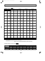
COOLING CAPACITY 60Hz
Service Ref.
Temperature
Outdoor D.B.
PK-2.5FLA3/4
T.C.
C.F.
(T.I.)
7.2
0.81
7.6
0.82
7.9
0.83
8.0
0.83
8.1
0.84
8.6
0.86
7.0
0.84
7.5
0.85
7.7
0.86
7.8
0.86
8.0
0.87
8.5
0.89
6.8
0.90
7.2
0.92
7.4
0.93
7.5
0.93
7.7
0.94
8.2
0.96
6.6
0.93
7.1
0.95
7.3
0.96
7.4
0.97
7.5
0.97
8.0
0.99
6.5
0.96
6.9
0.99
7.2
1.00
7.2
1.00
7.4
1.01
7.9
1.04
6.2
1.03
6.6
1.06
6.8
1.07
6.9
1.08
7.1
1.08
7.5
1.11
6.2
1.04
6.6
1.06
6.8
1.08
6.9
1.08
7.0
1.09
7.5
1.12
5.9
1.10
6.3
1.12
6.5
1.14
6.6
1.15
6.8
1.16
7.2
1.20
5.8
1.11
6.2
1.14
6.5
1.15
6.6
1.16
6.7
1.17
7.2
1.21
5.6
1.16
6.0
1.19
6.2
1.21
6.3
1.22
6.4
1.23
6.9
1.28
5.4
1.19
5.8
1.22
6.1
1.24
6.2
1.25
6.3
1.26
6.7
1.31
20
0.12
0.78
PK-2FLA3
T.C.
Indoor W.B.
16˚C
(60.8˚ F)
18˚C
(64.4˚ F)
21˚C
19˚C
(66.2˚ F)
19.4˚C
(67˚ F)
(69.8˚ F)
20˚C
(68˚ F)
22˚C
(71.6˚ F)
16˚C
(60.8˚ F)
18˚C
(64.4˚ F)
25˚C
19˚C
(66.2˚ F)
19.4˚C
(67˚ F)
(77˚ F)
20˚C
(68˚ F)
22˚C
(71.6˚ F)
16˚C
(60.8˚ F)
18˚C
(64.4˚ F)
30˚C
19˚C
(66.2˚ F)
19.4˚C
(67˚ F)
(86˚ F)
20˚C
(68˚ F)
22˚C
(71.6˚ F)
16˚C
(60.8˚ F)
18˚C
(64.4˚ F)
32.2˚C
19˚C
(66.2˚ F)
19.4˚C
(67˚ F)
(90˚ F)
20˚C
(68˚ F)
22˚C
(71.6˚ F)
16˚C
(60.8˚ F)
18˚C
(64.4˚ F)
35˚C
19˚C
(66.2˚ F)
19.4˚C
(67˚ F)
(95˚ F)
20˚C
(68˚ F)
22˚C
(71.6˚ F)
16˚C
(60.8˚ F)
18˚C
(64.4˚ F)
40˚C
19˚C
(66.2˚ F)
19.4˚C
(67˚ F)
(104˚ F)
20˚C
(68˚ F)
22˚C
(71.6˚ F)
16˚C
(60.8˚ F)
18˚C
(64.4˚ F)
40.6˚C
19˚C
(66.2˚ F)
19.4˚C
(67˚ F)
(105˚ F)
20˚C
(68˚ F)
22˚C
(71.6˚ F)
16˚C
(60.8˚ F)
18˚C
(64.4˚ F)
45˚C
19˚C
(66.2˚ F)
19.4˚C
(67˚ F)
(113˚ F)
20˚C
(68˚ F)
22˚C
(71.6˚ F)
16˚C
(60.8˚ F)
18˚C
(64.4˚ F)
46˚C
19˚C
(66.2˚ F)
19.4˚C
(67˚ F)
(115˚ F)
20˚C
(68˚ F)
22˚C
(71.6˚ F)
16˚C
(60.8˚ F)
18˚C
(64.4˚ F)
50˚C
19˚C
(66.2˚ F)
19.4˚C
(67˚ F)
(69.8˚ F)
20˚C
(68˚ F)
22˚C
(71.6˚ F)
16˚C
(60.8˚ F)
18˚C
(64.4˚ F)
52˚C
19˚C
(66.2˚ F)
19.4˚C
(67˚ F)
(125.5˚ F)
20˚C
(68˚ F)
22˚C
(71.6˚ F)
Evaporator airflow (CMM)
Bypass factors
S.H.F. at rating conditions
C.F.
(T.I.)
0.81
0.82
0.83
0.83
0.84
0.86
0.84
0.85
0.86
0.86
0.87
0.89
0.90
0.92
0.93
0.93
0.94
0.96
0.93
0.95
0.96
0.97
0.97
0.99
0.96
0.99
1.00
1.00
1.01
1.04
1.03
1.06
1.07
1.08
1.08
1.11
1.04
1.06
1.08
1.08
1.09
1.12
1.10
1.12
1.14
1.15
1.16
1.20
1.11
1.14
1.15
1.16
1.17
1.21
1.16
1.19
1.21
1.22
1.23
1.28
1.19
1.22
1.24
1.25
1.26
1.31
5.5
5.8
6.0
6.1
6.2
6.6
5.3
5.7
5.9
6.0
6.1
6.5
5.2
5.5
5.7
5.7
5.9
6.2
5.1
5.4
5.6
5.6
5.8
6.1
4.9
5.3
5.5
5.5
5.6
6.0
4.7
5.0
5.2
5.3
5.4
5.8
4.7
5.0
5.2
5.3
5.4
5.7
4.5
4.8
5.0
5.0
5.1
5.5
4.4
4.8
4.9
5.0
5.1
5.5
4.2
4.6
4.7
4.8
4.9
5.2
4.1
4.5
4.6
4.7
4.8
5.1
14
0.16
0.73
PK-3FLA2/3/4/5
T.C.
C.F.
(T.I.)
8.0
0.81
8.6
0.82
8.8
0.83
8.9
0.83
9.1
0.84
9.6
0.86
7.8
0.84
8.4
0.85
8.6
0.86
8.7
0.86
8.9
0.87
9.5
0.89
7.6
0.90
8.1
0.92
8.3
0.93
8.4
0.93
8.6
0.94
9.1
0.96
7.4
0.93
7.9
0.95
8.2
0.96
8.3
0.97
8.4
0.97
9.0
0.99
7.3
0.96
7.7
0.99
8.0
1.00
8.1
1.00
8.3
1.01
8.8
1.04
6.9
1.03
7.4
1.06
7.7
1.07
7.8
1.08
7.9
1.08
8.4
1.11
6.9
1.04
7.4
1.06
7.6
1.08
7.7
1.08
7.9
1.09
8.4
1.12
6.6
1.10
7.1
1.12
7.3
1.14
7.4
1.15
7.6
1.16
8.1
1.20
6.5
1.11
7.0
1.14
7.2
1.15
7.3
1.16
7.5
1.17
8.0
1.21
6.2
1.16
6.7
1.19
6.9
1.21
7.0
1.22
7.2
1.23
7.7
1.28
6.1
1.19
6.5
1.22
6.8
1.24
6.9
1.25
7.0
1.26
7.5
1.31
20
0.13
0.78
PK-4FLSA2/3/4
T.C.
C.F.
(T.I.)
11.0
0.81
11.8
0.82
12.1
0.83
12.3
0.83
12.5
0.84
13.2
0.86
10.8
0.84
11.5
0.85
11.9
0.86
12.0
0.86
12.2
0.87
13.0
0.89
10.4
0.90
11.1
0.92
11.4
0.93
11.6
0.93
11.8
0.94
12.6
0.96
10.2
0.93
10.9
0.95
11.3
0.96
11.4
0.97
11.6
0.97
12.4
0.99
10.0
0.96
10.6
0.99
11.0
1.00
11.1
1.00
11.4
1.01
12.1
1.04
9.5
1.03
10.2
1.06
10.5
1.07
10.7
1.08
10.9
1.08
11.6
1.11
9.5
1.04
10.1
1.06
10.5
1.08
10.6
1.08
10.8
1.09
11.6
1.12
9.1
1.10
9.7
1.12
10.0
1.14
10.2
1.15
10.4
1.16
11.1
1.20
9.0
1.11
9.6
1.14
9.9
1.15
10.1
1.16
10.3
1.17
11.0
1.21
8.6
1.16
9.2
1.19
9.5
1.21
9.7
1.22
9.9
1.23
10.6
1.28
8.4
1.19
9.0
1.22
9.3
1.24
9.5
1.25
9.7
1.26
10.4
1.31
28
0.14
0.73
Notes: 1. T.C.: Total capacity (kW) … (kcal/h)=(kW)x860, (Btu/h)=4x(kW)x860
C.F.(T.I.) : Correction factors of Total input(Indoor unit input + Outdoor unit input)
2. (°F)=32+9/5(°C)
Lower limit … Indoor : D.B. 21°C(70°F), W.B. 15.5°C(60°F), Outdoor : D.B. 21°C(70°F).
3. Guaranteed operating range(cooling)
Upper limit … Indoor : D.B. 35°C(95°F), W.B. 22.5°C(72.5°F), Outdoor : D.B. 52°C(125.5°F).
{
COOLING CAPACITY correction factors 60Hz
Service Ref.
PK-2FLA3
PK-2.5FLA2/3/4
PK-3FLA2/3/4/5
PK-4FLSA2/3/4
Refrigerant piping length (one way)
5m (16ft)
1.0
1.0
1.0
1.0
10m (33ft)
0.985
0.978
0.971
0.980
15m (49ft)
0.975
0.963
0.950
0.966
20m (66ft)
0.964
0.948
0.931
0.952
14
25m (82ft)
0.954
0.934
0.913
0.939
30m (98ft)
0.944
0.921
0.896
0.926
35m (115ft)
—
—
—
0.941
40m (131ft)
—
—
—
0.902
OC129A-1.qxp
01.10.1 7:33 PM
Page 15
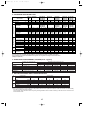
2. STANDARD OPERATION DATA
PK-1.6
FLA3
Service Ref.
Outdoor Indoor
side side
Refrigerant circuit
Electrical circuit
Total
MODE
Capacity
Input
Indoor unit
Service Ref.
Cooling Cooling Cooling
3900
5600
4600
1.49
2.52
2.60
PK-1.6 PK-2FLA3
FLA3
W
kW
Phase , Hz
Volts
Amperes
Outdoor unit
Service Ref.
Phase , Hz
Volts
Amperes
Discharge pressure
Suction pressure
Discharge temperature
Condensing temperature
Suction temperature
Refrigerant pipe length
Intake air
temperature
Discharge air temperature
Intake air
temperature
PK-2FLA3
Mpa
(o/f)
Mpa
(o/f)
˚C
˚C
˚C
m
D.B.˚C
W.B.˚C
D.B.˚C
D.B.˚C
W.B.˚C
1 , 50
220
0.32
PU-1.6
VLJA2
1 , 50
220
6.7
1.89
(19.3)
0.5
(5.1)
84
50
9
5
27
19
15.4
35
24
1 , 50
220
0.37
PU-2
VJA2
1 , 50
220
11.3
1.98
(20.2)
0.46
(4.69)
66
52
3
5
27
19
13.4
35
24
1 , 60
220
0.42
PU-2
NJA1
1 , 60
220
13.6
1.96
(20.0)
0.47
(4.79)
66
52
5
5
29
19
13.5
46
24
PK-2.5FLA2
PK-2.5FLA3
PK-2.5FLA4
Cooling Cooling
7000
6650
2.56
3.54
PK-2.5FLA2
PK-2.5FLA3
PK-2.5FLA4
1 , 50 1 , 60
220
220
0.44
0.44
PU-2.5 PU-2.5
VJA2 NJA1
1 , 50 1 , 60
220
220
11.4
15.8
2.05
2.13
(20.9) (21.7)
0.47
0.44
(4.79) (4.49)
74.3
87
52
54
10.3
10
5
5
27
29
19
19
14.1
14.1
35
46
24
24
PK-3FLA2
Cooling Cooling
7200
6900
3.28
4.19
PK-3FLA2
1 , 50
220
0.44
PU-3
VJA2
1 , 50
220
15.1
1.99
(20.3)
0.47
(4.79)
62
51
6
5
27
19
13.7
35
24
1 , 60
220
0.44
PU-3
NJA1
1 , 60
220
20.9
2.07
(21.1)
0.44
(4.49)
70
53
4
5
29
19
13.2
46
24
PK-3FLA3
PK-3FLA4
PK-3FLA5
Cooling Cooling
7900
6900
3.28
4.19
PK-3FLA3
PK-3FLA4
PK-3FLA5
1 , 50 1 , 60
220
220
0.44
0.44
PU-3 PU-3
VJC
NJA1
1 , 50 1 , 60
220
220
15.1
20.9
1.99
2.07
(20.3) (21.1)
0.47
0.44
(4.79) (4.49)
86
70
51
53
6
4
5
5
27
29
19
19
13.0
13.2
35
46
24
24
PK-3FLA2 PK-4FLSA2
PK-3FLA3 PK-4FLSA3
PK-3FLA4
PK-3FLA5 PK-4FLSA4
Cooling Cooling Cooling
7500
9800
9900
3.28
3.46
5.08
PK-3FLA2 PK-4FLSA2
PK-3FLA3 PK-4FLSA3
PK-3FLA4
PK-3FLA5 PK-4FLSA4
1 , 50
1 , 60
1 , 50
220
220
220
0.53
0.53
0.44
PU-4 PU-4
PU-3
YJSA3 TJSA3
VJB
1 , 50
3 , 50 3 , 60
220
220
220
12.4
5.7
14.0
1.94
1.80
1.93
(19.8)
(18.4) (19.7)
0.48
0.48
0.45
(4.85)
(4.89) (4.59)
76
65
74
51.4
49
52
5
6
5
5
5
5
27
27
29
19
19
19
13.4
13.9
13.2
35
35
46
24
24
24
Total Electrical circuit Refrigerant circuit Indoor side Outdoor side
The unit of pressure has been changed to Mpa on the international system of unit(SI unit system).
The converted score against the traditional unit system can be gotten according to the formula below.
1(Mpa)=10.2(O/F·G)
3. ADDITIONAL REFRIGERANT CHARGE (R-22…kg(lbs))
Service Ref.
PK-1.6FLA3
PK-2FLA3
PK-2.5FLA2/3/4
PK-3FLA2
PK-3FLA3/4/5
PK-4FLSA2/3/4
Outdoor unit precharged (kg)
(up to 20m)
VL---1.3,
V---1.79, N---1.9
V---2.4, N---2.4
V---3.08, Y---2.88, N---3.5
V---2.8, Y---2.8, N---3.5
VL---3.8, Y---4.6, T---4.6
20m (66ft)
0
0
0
0
0
0
Refrigerant
25m (82ft)
—
0.06(0.13)
0.06(0.13)
0.06(0.13)
0.06(0.13)
0.15(0.33)
piping length (one way)
30m (98ft)
35m (115ft)
—
—
0.12(0.26)
—
0.12(0.26)
—
0.12(0.26)
—
0.12(0.26)
—
0.30(0.66)
0.45(0.99)
40m (131ft)
—
—
—
—
—
0.6(1.32)
60Hz
50Hz
Frequency
4. OUTLET AIR SPEED AND COVERAGE RANGE
Configuration
Wall mounted
Model
Airflow
Air speed
Coverage rangew
Airflow
Air speed
Coverage rangew
m /min
m/sec.
m(ft)
m3/min
m/sec.
m(ft)
3
PK-1.6FLA
PK-2FLA
PK-2.5FLA
PK-3FLA
PK-4FLSA
13
4.0
9.1(30)
—
—
—
14
4.3
9.8(32)
14
4.3
9.8(32)
20
4.9
12.4(41)
20
4.9
12.4(41)
20
4.9
12.4(41)
20
4.9
12.4(41)
28
5.4
15.3(50)
28
5.4
15.3(50)
w The air coverage range is the value up to the position where the air speed is 0.25m/sec. when air is blown out horizontally
from the unit at the Hi notch position/
The coverage range should be used only as a general guideline since it varies according to the size of the room and furniture inside the room.
15
OC129A-1.qxp
6
01.10.1 7:33 PM
Page 16
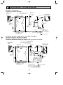
OUTLINES AND DIMENSIONS
Unit : mm
1. REMOTE CONTROLLER
57
18
3
58
19
CHECK TEST RUN
MODEL SELECT
˚C
AMPM
˚C
AM
PM
AMPM
NOT AVAILABLE
AM
PM
ON/OFF
NOT AVAILABLE
TEMP
162
153
ON / OFF
TEMP
55
PK-1.6FLA3
PK-2FLA3
PK-2.5FLA2, PK-2.5FLA3
PK-3FLA2, PK-3FLA3, PK-3FLA4
PK-4FLSA2, PK-4FLSA3
PK-2.5FLA4
PK-3FLA5
PK-4FLSA4
16
Front
(Height ut unit)
68- 5
hole
53
491
476
450
405
Gas pipe position
Liquid pipe position
2 X5 - 2.9 hole
for tapping screw
Knock out hole for
left-rear piping
Tapping screw
277
300
0
45
85
80
5
2.
323
276
229
R5
179
150
330
1250
60
24
0
190
Knock out hole for
left-rear piping
447
(375)
(178)
300
286X 2
227
2
Bass pipe
1 Liquid pipe
Drainage
50
2 tapping screws
for installation plate
0
35
53
80
130
177
Rear piping hole
13- 14
hole
(Necessary clearance for
Unit installation)
130 or less
Right side
Left side
60
(100 for left-hand
side piping)
150 or more
70
73
(Width of unit)
.5
35
Ref.pipes & drain pipe
Knock out hole for
left-hand side piping
150
174
224
Sleeve Through hole
90
90~ 100
Details of installation plate
w 1 Sleeves are available on
the market.
w 2 This size shows the lower
end of through hole.
2-unit hangers Unit cennter
50 or more
Service space required
around indoor unit
Gas pipe
Drain pipe
Lequid pipe
70
R5
2
215
80
271
47
70
25
318
3/8F
5/8F
2
1
976
479 Air outlet
Knock out hole
for piping
1100
Drainage(Flexible hole: length 1200)
685
635
Terminal block & pipe position
Lower side
500
(manual)
236
227
553
A
26
200
190
60
Installation bolt position
Right side
15 or less
bolt
A
B
Knock out hole
for piping
70
20
8
Knock out hole for under-piping
(2:1)
60
8
Knock-out hole for
night-hand side piping
(2:1)
Knock out hole for right piping
B
Knock out hole for piping
Terminal block for control
170
200
Right side
Terminal block
Air intake
Terminal block for
power supply
222
143
173
223
Service panel for
power supply connection
449 Air intake
Auto vanes
Lower side
48
16 -louvers
479 Air outlet
449 Air intake
168
1250
91
968 Air intake
213
4
Front
8
Pipe position
Left side
625
30 or more
180 or more
374
405
450
476
486
9
17
8
65
2. INDOOR UNIT
PK-1.6FLA3
PK-2FLA3
20
01.10.1 7:33 PM
70
OC129A-1.qxp
Page 17
Unit : mm
37
74
A
30
32-ø12 hole for bolt
66-ø6 hole for
tapping screw
Wall fixture
100
4 39
225
18
39
990
180
12-ø6 hole for
tapping screw
240
on left-hand side
C
30
455
39
610
91
314
285
19
245
90
25
Drain hose for
left-hand side piping
Knock out hole for
left piping
Left side
Range for left rear piping opening
280
Drainage range
on right-hand side
37
74
Unit center
10 91=(910)
900
18 Drainage range
98 32
B
37
65
Knock out hole for piping
A
100
4
340
30
10
184
30
30
80
29
280
18
45
45
Front
235
552 Air outlet
Liquid pipe
235
Refrigerant pipe. Drain pipe
Change vane (manual)
Under panel
Removable at left-hand
side piping
Knock out hole for under-piping
1120
Auto vane
Lower side
1110
Drain hose
45
62.5
13
Top
1400
1090 Air intake
235
552 Air outlet
235
Rear piping opening
60
183
240
235
Right side
Terminal block for control
197
B
Terminal block for power supply
Gas pipe
Drain hose
Bolt
15
C
Knock out hole for right piping
Refrigerant pipe. Drain pipe
Liquid pipe 9.52(3/8F)
Gas pipe 15.88(5/8F)
(Liquid pipe)
55 (Gas pipe) 107
120
111
42
01.10.1 7:33 PM
58
OC129A-1.qxp
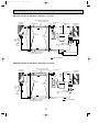
Page 18
PK-2.5FLA2, PK-2.5FLA3, PK-2.5FLA4
PK-3FLA2, PK-3FLA3, PK-3FLA4, PK-3FLA5
Unit : mm
19
295
225
39
180
314
285
19
245
90
Range for left rear piping opening
280
750
Drainage range
91
on right-hand side
595
12-ø6 hole for tapping screw
240
25
Knock out hole for left piping
340
Drain hose for left-hand side piping
37
74
C
30
13 91=(1183)
900
Drainage range
on left-hand side
18
Range for left rear piping opening
41-ø12 hole for bolt
18
1270
Unit center
98 32
Wall fixture
39
B
37
65
Knock out hole for wiring
Unit out line
37
74
A
30
84-ø6 hole for
tapping screw
100
4 39
A
100
4
Left side
235
10
184
30
30
80
29
280
30
Rear piping opening
Auto vane
45
1680
Front
235
Drain hose
235
694 Air outlet
183
Under panel
(Removable at left-hand side piping)
Refrigerant pipe. Drain pipe
Knock out hole for under-piping
235
Right side
240
(Liquid pipe)
B
55 (Gas pipe) 102
120
111
Terminal block for power supply
Gas pipe
C
Gas pipe 19.05(3/4F)
Liquid pipe 9.52(3/8F)
Bolt
Terminal block for control 15
Change vane (manual)
Lower side
1400
45
Knock out hole for right piping
235
Liquid pipe
1370 Air intake
45
1110 Drain hose
235
694 Air outlet
45
62.5
13
Top
42
PK-4FLSA2, PK-4FLSA3, PK-4FLSA4
58
01.10.1 7:33 PM
60
197
OC129A-1.qxp
Page 19
Unit : mm
OC129A-1.qxp
01.10.1 7:33 PM
7
Page 20
WIRING DIAGRAM
L
N
PK-1.6FLA3
PK-2FLA3
POWER SUPPLY
~(1 PHASE)
AC220-240V 50Hz
AC220V 60Hz
GRN/YLW
10.6VAC
220V
TB2
YLW
RED
240V
14.5VAC
T
MV
7
W.B
SW1
LS
ORN
230V
7
MF
LD1
CNB
W.R
1 3 5
FAN
CNV
VANE
POWER
12345678 12345
CN28
1 2 3 4 5 6
WHT
2 1
ON
OFF
L.TEST
CN70
WIRELESS
TO OUTDOOR UNIT
CONNECTING WIRES
DC12V
RT1
VANE
TWIN.1
SW2
CN2
TWIN.2
SW1
JR
TIMER
CN2A
INTAKE
2
1
RT2
CN23
123
CN2B
1
3 2 1
7
ON
OFF
YLW
2 1
CN20
SW3
TB4
ORN
2 1
PIPE
CN30
CN21
ZNR
OUTDOOR
CN51
MULTIPLE
F1
X4
X4
BRN
BRN
WHT
RED
RED
4 3 2 1 CN4T
TRANS
1 3 CNT
TRANS
1 3
F2
YLW
RED
CND
1 3
BLU
BLK
1 3 5
BLK
BLK
WHT
RED
I.B
Ru
C
REMORT
CONTROLLER
RED
PK-1.6FLA3
PK-2FLA3
SW1
ON
OFF
1 2 3 4 5 6 7 8
SYMBOL
C
CN2<I.B>
CN2A<I.B>
CN2B<I.B>
CN23<I.B>
CN28<I.B>
CN51<I.B>
F1,2<I.B>
I.B
JR
NAME
SYMBOL
NAME
FAN MOTOR CAPACITOR
LD1<W.B> RUN INDICATOR LED
TIMER ADAPTOR CONNECTOR
MF
FAN MOTOR
TRANSMISSION WIRES No.1 CONNECTOR
MV
VANE MOTOR
TRANSMISSION WIRES No.2 CONNECTOR
ROOM TEMPERATURE THERMISTOR
RT1
VANE POSITION CONNECTOR
(0%/15k",25°C/5.4k" DETECT)
TIME SHORTENING CONNECTOR
PIPE TEMPERATURE THERMISTOR
RT2
MULTIPLE CONNECTOR
(0%/15k". 25°C/5.4k" DETECT
FUSE(6.3A 250V)
Ru<W.B> RECEIVING UNIT
INDOOR CONTROLLER BOARD
SW1<I.B> FUNCTION SWITCH
FUNCTION SELECTOR JUMPER RESISTORS
SW2<I.B> UNIT SELECTOR SWITCH
SYMBOL
SW3<I.B>
SW1<W.B>
T
TB2
TB4
X4<I.B>
ZNR
W.B
W.R
SW1
ON
OFF
1 2 3 4 5 6 7 8
NAME
EMERGENCY OPERATION SWITCH
ON/OFF SWITCH
TRANSFORMER
POWER SUPPLY TERMINAL BLOCK
INDOOR/OUTDOOR CONNECTING WIRE
TERMINAL BLOCK
FAN MOTOR RELAY
VARISTOR
WIRELESS REMOTE CONTROLLER BOARD
WIRELESS REMOTE CONTROLLER
NOTES:
1. Since the indoor fan motor (MF) is connected with 220V power, using 230, 240V power will require a setting change of the dip switch (SW1<I.B>) on the
indoor controller board as shown is fig:w1.
SW1
SW1
fig
w1
Indoor fan motor (MF) for 230,240V.
ON
OFF
ON
OFF
12345678
12345678
2. Since the outdoor side electric wiring may change be sure to check the outdoor unit electric wiring for servicing.
3. Since the indoor transformer (T) is connected with 220V power, if 230,240V power is used. Change the wiring connection showing fig * : 2.
fig
w2
When power supply is
230V
220V
220V YELLOW
230V ORANGE
240V RED
4. Symbols used in wiring diagram above are,
: Connector,
: Terminal block.
5. Emergency operation
If remote controller of microcomputer fails but there is no other trouble, emergency operation is possible by setting dip switch (SW3<I.B>) on the indoor controller board.
[Check items]
(1) Compressor and fan.
(2) Check the trouble position using self diagnostic function. If the result of self diagnosis indicates protective device such as freeze protection is functioning
emergency operation is not possible unless the cause is removed.
Emergency operation will be continuous operation mode due to power ON/OFF (ON/OFF with remote controller is not possible).
[Emergency operation procedure]
(1) Set the dip switch (SW3<I.B>) on the indoor controller board to 1 • 2 on and 3 off for cooling.
(2) Turn on outdoor unit side circuit breaker, then indoor unit side circuit breaker in this order.
(3) During emergency operation indoor fan runs at high speed but automatic vane remains stop.
If vane is closed open the vane by hands/
(4) Thermostat will not function.
(5) Emergency cooling should be limited to 10 hours maximum.
(The indoor unit heat exchanger may freeze).
20
OC129A-1.qxp
01.10.1 7:33 PM
Page 21
PK-2.5FLA2, PK-2.5FLA3, PK-2.5FLA4
PK-3FLA2, PK-3FLA3, PK-3FLA4 , PK-3FLA5
PK-4FLSA2, PK-4FLSA3, PK-4FLSA4
L
N
POWER SUPPLY
~(1 PHASE)
AC220-240V 50Hz
AC220V 60Hz
GRN/YLW
10.6VAC
220V
MF
TB2
RED
ORN
YLW
230V
C
14.5VAC
BRN
RED
BRN
RED
LD1
SW1
7
FAN1
CND 1 3
1 3 5
F2
4 3 2 1 CN4T
TRANS
1 3 CNT
TRANS
POWER
F1
6
X4
6
1
SW3
7
MODELS
PK-2.5FLA
PK-3FLA
ON
OFF
NAME
FAN MOTOR CAPACITOR
TIMER ADAPTOR CONNECTOR
TRANSMISSION WIRES No.1 CONNECTOR
TRANSMISSION WIRES No.2 CONNECTOR
DRAIN LEFT-UP MECHANISM
VANE POSITION CONNECTOR
TIME SHORTENING CONNECTOR
MULTIPLE CONNECTOR
FUSE(6.3A 250V)
INDOOR CONTROLLER BOARD
FUNCTION SELECTOR JUMPER RESISTORS
2
1
TO OUTDOOR UNIT
CONNECTING WIRES
DC12V
RT2
RT1
PK-4FLSA
ON
OFF
12345678
SYMBOL
C
CN2<I.B>
CN2A<I.B>
CN2B<I.B>
CN23<I.B>
CN27<I.B>
CN28<I.B>
CN51<I.B>
F1,2<I.B>
I.B
JR
TB4
REMOTE
CONTROLLER
CN28
12345678 12345
SW1
CN20
INTAKE
W.R
MV
L.TEST
1 2 3 4 5 6
CN70
SW2 WIRELESS
ORN
YLW
2 1
TWIN-1
ON
OFF
CN2
TWIN-2
SW1
JR
PIPE
TIMER
CN2A
CN21
DRAIN
CN27
123
CN2B
CN50
1
D.U.M
ON
OFF
3 2 1
1 2 3 4 5
CN30
VANE
ZNR
X4
OUTDOOR 2 1
CN51
MULTIPLE
CN6V
W.B
CNB
Ru
YLW
RED
BLU
WHT
T
RED
WHT
BLK
I.B
7
240V
12345678
SYMBOL
NAME
MF
FAN MOTOR
MV
VANE MOTOR
ROOM TEMPERATURE THERMISTOR
RT1
(0%/15k",25°C/5.4k" DETECT)
PIPE TEMPERATURE THERMISTOR
RT2
(0%/15k". 25%/5.4k" DETECT
Ru<W.B> RECEIVING UNIT
SW1<I.B> FUNCTION SWITCH
SW2<I.B> UNIT SELECTOR SWITCH
SW3<I.B> EMERGENCY OPERATION SWITCH
TRANSFORMER
T
SYMBOL
NAME
TB2
POWER SUPPLY TERMINAL BLOCK
INDOOR/OUTDOOR CONNECTING WIRE
TB4
TERMINAL BLOCK
X4<I.B> FAN MOTOR RELAY
VARISTOR
ZNR
SW1<W.B> ON/OFF SWITCH
LD1<W.B> RUN INDICATOR LED
WIRELESS REMOTE CONTROLLER BOARD
W.B
WIRELESS REMOTE CONTROLLER
W.R
NOTES:
1. Since the indoor fan motor (MF) is connected with 220V power, using 230, 240V power will require a setting change of the dip switch (SW1<I.B>) on the
indoor controller board as shown is fig:w1.
SW1
SW1
fig
w1
Indoor fan motor (MF) for 230,240V.
ON
OFF
12345678
ON
OFF
12345678
2. Since the outdoor side electric wiring may change be sure to check the outdoor unit electric wiring for servicing.
3. Since the indoor transformer (T) is connected with 220V power, if 230,240V power is used. Change the wiring connection showing fig * : 2.
fig
w2
When power supply is
230V
220V
220V YELLOW
230V ORANGE
240V RED
4. Symbols used in wiring diagram above are,
: Connector,
: Terminal block.
5. Emergency operation
If remote controller of microcomputer fails but there is no other trouble, emergency operation is possible by setting dip switch (SW3<I.B>) on the indoor controller board.
[Check items]
(1) Compressor and fan.
(2) Check the trouble position using self diagnostic function. If the result of self diagnosis indicates protective device such as freeze protection is functioning
emergency operation is not possible unless the cause is removed.
Emergency operation will be continuous operation mode due to power ON/OFF (ON/OFF with remote controller is not possible).
[Emergency operation procedure]
(1) Set the dip switch (SW3<I.B>) on the indoor controller board to 1 • 2 on and 3 off for cooling.
(2) Turn on outdoor unit side circuit breaker, then indoor unit side circuit breaker in this order.
(3) During emergency operation indoor fan runs at high speed but automatic vane remains stop.
(4) Thermostat will not function.
(5) Emergency cooling should be limited to 10 hours maximum.
(The indoor unit heat exchanger may freeze).
21
OC129A-1.qxp
8
01.10.1 7:33 PM
Page 22
REFRIGERANT SYSTEM DIAGRAM
PK-1.6FLA3 / PU-1.6VLJA2
PK-2FLA3 / PU-2VJA2, PU-2NJA1
INDOOR UNIT
PK-1.6
PK-2
Low pressure
switch
Refrigerant pipe [15.88(5/8)
(with insulator) option
Charge
pIug
Flexible tube
Ball
valve
Distributor
Indoor heat
exchanger
Check plug
OUTDOOR UNIT
PU-1.6/2J series
High pressure
switch
Outdoor heat
exchanger
Flared
connection
Flared
connection
Indoor coil
thermistor
RT2
Strainer
Accumulator
Compressor
Capillary tube
for injection
(Only PU-2VJA2)
PU-2NJA1
Capillary tube
Ball valve
(with service port)
Refrigerant pipe [9.52(3/8)
(with insulator) option
PU-1.6 (O.D.3.2 I.D.1.8 L900)
PU-2 (O.D.4.0 I.D.2.0 L430)
flow of refrigerant
PK-2.5FLA2, PK-2.5FLA3, PK-2.5FLA4, / PU-2.5VJA2, PU-2.5NJA1
PK-3FLA2 / PU-3VJA2, PU-3YJA3, PU-3NJA1
PK-3FLA3, PK-3FLA4, PK-3FLA5 / PU-3NJA1
PK-4FLSA2, PK-4FLSA3, PK-4FLSA4, / PU-4VLJSA2, PU-4YJSA3, PU-4TJSA2
INDOOR UNIT
PK-2.5
PK-3
PK-4
PK-2.5 / PK-3 Refrigerant pipe [15.88(5/8)
(with insulator) option
PK-4 Refrigerant pipe [19.05(3/4)
(with insulator) option
Low pressure
switch
Flexible tube
Charge
Ball
valve pIug
Distributor
Indoor heat
exchanger
High pressure
switch
OUTDOOR UNIT
PU-2.5/3J series
PU-4J series
Check
pIug
Flared
connection
Strainer
Flared
connection
Indoor coil
thermistor
RT2
Outdoor heat
exchanger
Accumulator
Compressor
Capillary
tube
Capillary tube for
injection Only
PU-2.5NJA1 PU-3YJA2
PU-2.5VJA2 PU-3YJA3
PU-3NJA1 PU-4YJSA2
PU-3VJA2 PU-4YJSA3
PU-4TJSA2
Refrigerant pipe [ 9.52(3/8)
(with insulator) option
Ball valve
(with service port)
flow of refrigerant
Capillary tube size
PU-2.5 (O.D.3.2 I.D.1.6 L760) 2pcs
PU-3 (O.D.3.2 I.D.1.8 L800) 2pcs
PU-4 (O.D.3.2 I.D.2.0 L840) 2pcs
22
OC129A-1.qxp
01.10.1 7:33 PM
Page 23
PK-3FLA3, PK-3FLA4, PK-3FLA5 / PU-3VJC , PU-3YJC
Refrigerant pipe [15.88(5/8")
(with insulator) option
Low pressure
Flexible tube
strainer
switch
Indoor heat
exchanger
Ball
valve
strainer
Charge
pIug
High pressure
switch
Outdoor heat
exchanger
Check
pIug
Flared
connection
strainer
Flared
connection
Indoor coil
thermistor
RT2
Accumulator
Compressor
Capillary tube
Distributor
with
strainer
(O.D.3.2 o I.D.1.8 o L800)
o2pcs
Ball valve
(with service port)
D.P.R.
(Discharge pressure regulator)
Refrigerant pipe [ 9.52(3/8")
(with heat insulator) option
flow of refrigerant
PK-3FLA3, PK-3FLA4, PK-3FLA5 / PU-3VJB , PU-3YJB
Refrigerant pipe [15.88(5/8")
(with insulator) option
Low pressure
Flexible tube
strainer
switch
Indoor heat
exchanger
Ball
valve
strainer
Charge
pIug
High pressure
switch
Outdoor heat
exchanger
Check
pIug
Flared
connection
strainer
Flared
connection
Indoor coil
thermistor
RT2
Accumulator
Compressor
Capillary tube
Distributor
with
strainer
(O.D.3.2 oI.D.1.8 oL800)
o2pcs
Ball valve
(with service port)
Refrigerant pipe [ 9.52(3/8")
(with heat insulator) option
23
flow of refrigerant
OC129A-1.qxp
9
01.10.1 7:33 PM
Page 24
OPERATION FLOW-CHART
1. Main operation
START
1
NO
POWER SUPPLY
Live
YES
NO
NO
ON/OFF
button ON
YES
Protection device
Self hold reset
STOP
YES
Abnormal
operation mode
Protection device
Self hold
NO
POWER lamp ON
Self-diagnostic function
Indicate & Memory
EMERGENCY
ALL STOP
<Note 4>
<Note 5>
MODE SELECT
button
DRY
COOL
COOL OPERATION
DRY OPERATION
Note1. The unit starts operation by pressing the ON/OFF switch when unit is OFF.
During operation, the unit stops operation by pressing the ON/OFF switch.
In addition, operation can be turned ON/OFF with the centralized remote controller or the remote switch.
Note2. The factors which cause “abnormal operation mode” are as follows.
● Outdoor unit abnormal operation.
● Fault of room temperature thermistor(RT1).
● Fault of indoor coil thermistor(RT2).
● Indoor coil frost protection mode.
● Fault of drain sensor(DS).
● Drain water overflow prevention mode.
Refer to page 30 for abnormal operation, mode details.
Note3. The indoor fan runs on the low speed for 1 minute to eliminate remaining heat.
Note4. The compressor will not start for 3 minutes after the stop.
Note5. The thermostat is continuously ON during the test run.
Note6. Refer to page 31 for coil frost protection.
Note7. Range A : Indoor coil temperature is more than 5 degrees above room temperature.
Range B : Indoor coil temperature is within 5 degrees either way of room temperature.
Range C : Indoor coil temperature is more than 5 degrees below room temperature.
24
OC129A-1.qxp
01.10.1 7:33 PM
Page 25
2. COOL operation
YES
COOL operation
3 min. delay
NO
YES
6-minute
time delay
Allowance
NO
NO
NO
YES
Compressor start
3 minutes elapse
Coil frost
protection
check mode
6-minute time delay
<Note 7>
Coil frost
protection
<Note 8>
Allowance set
NO
Range C
NO
YES
NO
Compressor
start 10 minutes
elapse
Allowance release
Indoor coil
temperature
10°C or bellow
Coil frost
prevention
NO
<Note 6>
Compressor
themostat ON
YES
NO
NO
YES
Continue
1 minute
YES
Fan speed LOW
3-minute time delay
Compressor
start 16 minutes
elapse
YES
NO
Allowance release
NO
Coil frost
prevention release
NO
Fan speed LOW
5 minutes elapse
YES
Indoor coil
temperature
1°C or below
Outdoor unit abnormality
check mode
NO
Compressor ON
Coil frost
prevention set
Compressor ON
Compressor OFF
1
25
OC129A-1.qxp
01.10.1 7:33 PM
Page 26
3. DRY operation
Dry operation
<Note 8>
YES
Room temperature
18°C or below
NO
Compressor ON
NO
YES
Compressor ON
3 min. elapse
NO
NO
Compressor ON
3 min. delay
NO
YES
<Note 6>
Compressor
thermostat ON
<Note 6>
YES
YES
Compressor ON
time completed
YES
Compressor
thermostat ON
NO
NO
Compressor OFF
10 minutes completed
YES
YES
Compressor OFF
10-minute timer start
<Note 9>
Compressor ON
time set
YES
Compressor OFF
Compressor ON
<Note 10>
<Note 10>
Fan stop
Fan speed LOW
1
Note8. When room temperature is 18°C or below, the compressor can not turn ON. When the room temperature rises to 18°C or
above, the compressor will start operation after a 3-minute time delay.
Note9. Refer to page 30 for the compressor operation time.
Note10. In DRY operation, the indoor fan runs on the low speed during the compressor ON and stops during the compressor OFF.
26
OC129A-1.qxp
01.10.1 7:33 PM
10
Page 27
MICROPROCESSOR CONTROL
1. OUTLINE OF MICROPROCESSOR CONTROL
REMOTE CONTROLLER
INPUT to remote controller
●Processes and transmits orders.
OUTPUT to remote controller
● Indication LCD lights.
● OFF-ON switching.
● COOL • DRY • FAN selector switching.
● HIGH-LOW fan speed switching.
● TIMER mode selector-switching
● Timer setting.
● Self diagnostic troubleshooting.
● TEST RUN switching.
● CHECK mode switching.
● AUTO Vane setting.
˚C
AM
PM
AM
PM
NOT AVAILABLE
ON / OFF
TEMP
Indoor unit
PK-1.6FLA3
PK-2FLA3
PK-2.5FLA2/3
PK-3FLA2/3/4
PK-4FLSA2/3
PK-2.5FLA4
PK-3FLA5
PK-4FLSA4
INPUT from indoor unit
● Room temperature thermistor.
● Indoor coil thermistor.
OUTPUT to indoor unit
INDOOR CONTROLLER BOARD
● Receives orders from remote controller and temperature
data from indoor unit.
● Processes orders and data.
● Controls indoor and outdoor operation.
● Self diagnostic function
w System control operation.<Optional>
w Emergency operation
● Fan: ON-OFF.
● Fan speed: HIGH-LOW.
● AUTO vane’s angle setting.
● Emergency stop.
Non-polar, two (2) - core cable
INPUT from outdoor unit
● Compressor protection device working.
12VDC
Independent Control of
Outdoor Unit
OUTPUT UNIT
● Receives orders from
indoor controller.
● Emergency stop.
OUTPUT from outdoor unit
● Compressor motor and outdoor fan motor : ON-OFF.
27
Outdoor unit
OC129A-1.qxp
01.10.1 7:33 PM
Page 28
2. INDOOR UNIT CONTROL
2-1COOL operation
<How to operate>
1 Press [ ON/OFF button.
2 Press MODE button to set operation mode to COOL
˚C
.
/
/
3 Set desired temperature with
or
button.
button.
NOTE: 1. Set temperature changes by 1 °C in the range 19-30 °C
AM
PM
AM
PM
NOT AVAILABLE
ON / OFF
/
/
each TEMP
or
button is pressed.
2. Set temperature is displayed on the LCD.
TEMP
PK-1.6FLA3
PK-2FLA3
PK-2.5FLA2/3
PK-3FLA2/3/4
PK-4FLSA2/3
PK-2.5FLA4
PK-3FLA5
PK-4FLSA4
<COOL operation time chart>
Operation starts by
POWER button
ON.
Room temperature
becomes equal to
set temperature.
Room temperature
rises above set
temperature.
Operation stops by
POWER button
OFF.
ON
Thermostat
OFF
LOW or HIGH
ON
Indoor fan
OFF
Depends on remote controller setting
ON
Auto vane
LOW or HIGH
OFF
CLOSE
CLOSE
ON
Compressor
OFF
MIN. 3 minutes w1
w1 Even if the room temperature rises above the set temperature during this period, the compressor will not start until this period has ended.
(1)Compressor control
1 3-minute time delay
To prevent overload, the compressor will not start within 3 minutes after stop.
2 The compressor runs when the room temperature is higher than the set temperature.
The compressor stops when the room temperature is equal to or lower than the set temperature.
3 The compressor stops in check mode or during protective functions.
4 Coil frost prevention
To prevent indoor coil frost, the compressor will stop when the indoor coil thermistor (RT2) reads 1°C or below after the
compressor has been continuously operated for 16 minutes or more. The coil frost prevention is released under any of the
following conditions.
● The indoor coil thermistor rises to 10°C or above.
● The room temperature becomes equal to or lower than the set temperature.
● COOL mode is stopped or changed to another mode.
NOTE : By cutting the jumper wire JR02 on the indoor controller board, the temperature to start coil frost prevention
changes from 1°C to - 3°C
28
OC129A-1.qxp
01.10.1 7:33 PM
Page 29
5 Coil frost protection
When the indoor coil temperature becomes - 15°C or below, coil frost protection will proceed as follows.
<Start condition>
After the compressor has been continuously operated for 3 minutes or more, and the indoor coil temperature has been 15°C or below for 3 minutes, the coil frost protection will start.
<Coil frost protection>
Compressor stops for 6 minutes, and then restarts.
If the start condition is satisfied again during the first 10 minutes of compressor operation, both the indoor and outdoor units
stop, and the remote controller displays this occurrence.
<Termination conditions>
Coil frost protection released when the start condition is not satisfied again during the allowance, or when the COOL mode
stops changes another mode.
(2)Indoor fan control
Indoor fan speed depends on the remote controller setting.
However, if an outdoor unit abnormality is detected, the indoor fan speed will be LOW, regardless of the remote controller
setting.
(3)Auto vane control
Auto vane position depends on the remote controller setting.
(4)Detecting abnormalities in the outdoor unit
After the compressor has been continuously operated for 3 minutes, if the difference between the indoor coil temperature
and the room temperature is out of RANGE C for 1 minute, the indoor fan speed will turn to LOW. Five minutes later, if the
difference is still out of RANGE C, the outdoor unit is functioning abnormally. Thus, the compressor will stop and the remote
controller will display this occurrence.
RANGE A : Indoor coil temperature is more than 5 degrees above room temperature.
RANGE B : Indoor coil temperature is within 5 degrees either way of room temperature.
RANGE C : Indoor coil temperature is more than 5 degrees below room temperature.
(5)AUTO VANE CONTROL
1 Frequency judgement
When the unit operates for the first time after the circuit breaker turned to ON, the frequency, 50Hz or 60Hz, is judged by
the horizontality sensing switch. If The frequency cannot be judged immediately for some reason, the sensing operation
continues for 3 minutes with the vane motor at ON.
If the frequency cannot be judged yet after 3-minute sensing, the vane motor turns to OFF. But the AIR DISCHARGE
DIRECTION display continues to be indicated.
2 During cooling operation
When the cooling operation starts, the vane is automatically set to the horizontal However, the desired direction among four
below-listed can be selected with the vane button on the remote controller.
a) 10°
b) 30° downward
c) 60° downward (PK-2.5, 3, 4FL(S)A) / 50° downward (PK-1.6, 2FLA)
d) 70° downward (PK-2.5, 3, 4FL(S)A) / 60° downward (PK-1.6, 2FLA)
10°
e) Automatic swing (only PK-2.5, 3, 4FL(S)A)
NOTE : 30° is available only when the fan speed is HIGH.
<AUTO RETURN>
When discharge 50°, 60° or 70° continues for 1 hour with the fan speed at LOW, the
discharge direction turns to the horizontal discharge automatically.
NOTE1 : After that, 50°, 60° or 70° is available by setting with the remote controller,
and it continues for 1 hour.
NOTE2 : If the discharge direction changes from 50°, 60° or 70° , the direction
returns to the horizontal discharge when 1 hour has passed since the discharge 60°
started.
NOTE3 : If the discharge direction changes from 50° or 60° (or 70° ) to the horizontal
discharge, the 1-hour timer to return the horizontal discharge is cancelled.
3 During the operation OFF, the auto vane is in the airflow shut-off position.
4 When the vane motor is out of order or the connector is badly connected, the
remote controller display of the remote controller does not change.
29
30°
60° (PK-2.5/3/4)
50° (PK-1.6/2)
70° (PK-2.5/3/4)
60° (PK-1.6/2)
Automatic
swing
(PK-2.5/3/4)
OC129A-1.qxp
01.10.1 7:33 PM
Page 30
2-2 DRY operation
<How to operate>
1 Press [ ON/OFF button.
˚C
2 Press MODE button to set operation mode to DRY
AM
PM
.
/
/
3 Set desired temperature with
or
button.
NOTE: 1. Set temperature changes by 1 °C in the range 19-30 °C
AM
PM
NOT AVAILABLE
ON / OFF
/
/
each TEMP
or
button is pressed.
2. Set temperature is displayed on the LCD.
TEMP
PK-1.6FLA3
PK-2FLA3
PK-2.5FLA2/3
PK-3FLA2/3/4
PK-4FLSA2/3
PK-2.5FLA4
PK-3FLA5
PK-4FLSA4
Operation starts by
POWER button
ON.
Room temperature
becomes equal to
set temperature.
Room temperature
rises above set
temperature.
Operation stops by
POWER button
OFF.
ON
Thermostat
OFF
LOW speed
ON
Indoor fan
OFF
Depends on remote controller setting
ON
Auto vane
LOW speed
OFF
CLOSE
CLOSE
ON
Compressor
OFF
MIN. 3 minutes w2
w2 Even if the room temperature rises above the set temperature during this period, the compressor will not start until this period has ended.
(1)Compressor control
1 3-minute time delay
To prevent overload, the compressor will not start within 3 minutes after stop.
2 The compressor runs when the room temperature is higher than the set temperature.
The compressor stops when the room temperature is equal to or lower than the set temperature.
3 The compressor stops in check mode or during protective functions.
4 The compressor will not start when the room temperature is below 18 °C. The compressor starts intermittent operation
when the power is turned ON with room temperature above 18 °C. The compressor ON/OFF time depends on the thermostat ON/OFF and the room temperature as follows.
After 3-minute compressor operation,
● If the room temperature thermistor reads above 28 °C with thermostat ON, the compressor will operate will operate for 6
more minutes and then stop for 3 minutes.
● If the room temperature thermistor reads 26 °C ~ 28 °C with thermostat 0N, the compressor will operate for 4 more minutes and then stop for 3 minutes.
● If the room temperature thermistor reads 24 °C ~ 26 °C with thermostat ON, the compressor will operate for 2 more minutes and then stop for 3 minutes.
● If the room temperature thermistor reads below 24 °C with thermostat ON, the compressor will stop for 3 minutes.
●If the thermostat is OFF, regardless of room temperature, the compressor will stop for 10 minutes.
5 Coil frost protection
Coil frost protection in DRY operation is the same as in COOL operation.
6 Coil frost prevention
Coil frost prevention does not operate in DRY operation.
30
OC129A-2.qxp
01.10.1 7:33 PM
Page 31
(2) Indoor fan control
The indoor fan runs on LOW speed during compressor operation. The fan speed cannot be changed with the remote controller.
Also, the indoor fan does not run during compressor OFF.
(3)Auto vane control
Same as in COOL operation.
(4)Detecting abnormalities in the outdoor unit
An abnormality in the outdoor unit can not be detected in DRY operation.
2-3 FAN operation
<How to operate>
1 Press POWER ON/OFF button.
CHECK TEST RUN
MODEL SELECT
˚C
AMPM
˚C
AM
PM
AMPM
NOT AVAILABLE
AM
PM
NOT AVAILABLE
ON/OFF
TEMP
ON / OFF
FAN
AUTO STOP
VANE
AUTO START
MODE
2 Press MODE button to set operation mode to Fan
.
(1) Indoor fan control
The indoor fan speed depends on the remote controller setting.
(2) Auto vane control
The auto vane position depends on the remote controller setting.
CLOCK
MODE
FAN
VANE
STOP
START
HR
MIN.
CHECK LOUVER
SET
PK-1.6FLA3
PK-2FLA3
PK-2.5FLA2/3
PK-3FLA2/3/4
PK-4FLSA2/3
h
TEST RUN
min
RESET
CLOCK
PK-2.5FLA4
PK-3FLA5
PK-4FLSA4
2-4 TIMER operation
CHECK TEST RUN
MODEL SELECT
˚C
AMPM
˚C
AM
PM
AMPM
NOT AVAILABLE
AM
PM
NOT AVAILABLE
ON/OFF
TEMP
<How to operate>
1 Push POWER ON/OFF button.
2 Check if or not the current time is correct.
AUTO STOP
AUTO START
3 Push the STOP /
or START /
button and select the desired
time.
min
h
4 Set the timer time using HR /
and MIN. /
buttons.
ON / OFF
MODE
FAN
AUTO STOP
VANE
AUTO START
CLOCK
MODE
FAN
VANE
STOP
START
HR
MIN.
CHECK LOUVER
TEST RUN
SET
PK-1.6FLA3
PK-2FLA3
PK-2.5FLA2/3
PK-3FLA2/3/4
PK-4FLSA2/3
h
min
RESET
CLOCK
PK-2.5FLA4
PK-3FLA5
PK-4FLSA4
31
OC129A-2.qxp
01.10.1 7:33 PM
Page 32
Measure an impedance between the power supply terminal block and ground with a 500V
Megger and check that it is equal to or greater than 1.0M".
2-5 Test run
PK-1.6FLA3, PK-2FLA3
PK-2.5FLA2/3, PK-3FLA2/3/4
PK-4FLSA2/3
(1) Turn on the main power of unit.
(2) Turn the adjusting switch on the back of the
wireless remote controller to “SET”
CHECK and TEST RUN will
start flashing.
Wireless remote controller with backside battery
cover removed Display will start finishing.
˚C
★(3) Push the MIN button TEST RUN and
the operating mode will be displayed (Refer
to the illustrated sample display at left)
AM
PM
AM
PM
Turn the adjusting switch to "SET"
Display will start flashing
NOT AVAILABLE
Nrm Set
23
901
CLOCK
45
MODE
Reset
After refiling batteries.
Press the reset button.
8
67
★(4) Push the MODE button, change the
mode to “FAN” and make sure that there
will be blowout of air.
ON / OFF
FAN
VANE
STOP
START
HR
MIN.
★(5) Push the MODE button, change the mode
to COOL and make sure that there will be
blowout of cool air.
★(6) Push the FAN button and make sure that
there will be strong (or weak) blowout of air.
ON / OFF
For operations marked "★", point the transmitter to the
wireless receiver, and make sure that you will hear a
short beep from the receiver.
★(7) Push the VANE button and verify the
operation of the auto vane.
★(8) Push the POWER ON/OFF button and
cancel the test run.
(9) After completing a test run, be sure to
turn the adjusting switch back to “Nrm”.
● The test run automatically stops in 2 hours.
● Set temperature is not displayed during test run.
Test run
PK-2.5FLA4
PK-3FLA5
PK-4FLSA4
A
TEST RUN
TEMP
ON/OFF
6
FAN
AUTO STOP
VANE
AUTO START
4
MODE
3
5
CHECK LOUVER
Measure an impedance between the power supply terminal block and ground
with a 500V Megger and check that it is equal to or greater than 1.0M".
1 Turn on the main power to the unit.
TEST RUN
2 Press the
button twice continuously.
(Start this operation from the status of remote controller display turned off.)
A TEST RUN and current operation mode are displayed.
MODE
3 Press the
(
) button to activate COOL mode, then check
whether cool air is blown out from the unit.
FAN
4 Press the
button and check whether strong air is blown out from the
unit.
VANE
5 Press the
button and check whether the auto vane operates properly.
6 Press the ON/OFF button to stop the test run.
Note:
• Point the remote controller towards the indoor unit receiver while following steps 2 to 6.
• It is not possible to run the in FAN, DRY mode.
h
min
TEST RUN
2
SET
RESET
CLOCK
32
OC129A-2.qxp
01.10.1 7:33 PM
Page 33
2-6 Emergency operation
When the remote controller or microprocessor malfunctions and no other trouble exists, emergency operation is available
by setting the dip switch on the controller board.
[Check items]
(1) Make sure the compressor and the fans are running normally.
(2) Locate the trouble with the self-diagnostic function.
If the self-diagnostic function indicates that the protection
device (such as coil frost protection) is functioning, the sources
must be removed before attempting emergency operation.
Emergency operation ON/OFF is activated not with the remote
controller but with the circuit breaker.
[Emergency operation produce]
(1)Cooling operation is available by setting the dip switch SW3
1and 2 ON and 3 OFF on the indoor controller board.
(2)To start emergency operation, turn the outdoor side circuit
breaker ON first, and then the indoor side circuit breaker ON.
(3)During emergency operation, the indooor fan runs on HIGH
speed, the compressor runs continuously, and the louver
stops.
(4)Thermostat will not function.
(5)Do not use emergency cooling operation for more than 10
hours, as the indoor coil may freeze.
SW3
SW3 INDOOR CONTROLLER BOARD
ON
OFF
1 2 3
COOLING
2-7 Function of jumper wire and dip switch on indoor controller board
1. Jumper wire
1 JR01:Jumper wire for the auto vanes
Cut JR01 for the unit WITHOUT auto vanes.
2 JR02:Jumper wire for the temperature to start coil frost prevention
Cutting JR02 changes the temperature from +1°C to -3°C.
3 JR03:Jumper wire for set temperature adjustment in HEAT mode
In HEAT operation, heated air stagnates in the upper part of the room. The indoor unit installed in the upper part of
the room will detect the air temperature higher than the actual temperature in the living space. This difference is
about 4 degrees. Therefore, the temperature detected by the room temperature thermistor should be corrected 4
degrees down. The unit with JR04 attached will make this adjustment.
4 JR04:Jumper wire for the indoor fan speed during thermostat OFF in HEAT mode
Cutting JR04 Changes the speed from Extra-Low to Low.
5 JR05:Jumper wire for detecting abnormalities in the outdoor unit
Cutting JR05 makes this detection unavailable. (Occurrence of abnormality can not be detected.)
6 JR06:Jumper wire for auto restart function
Cutting JR06 makes the auto restart function available.
2.Dip switch
1 SW1 (Function switch)
ON
OFF
1 2 3 4 5 6 7 8
SW1-1) Switch for power supply
ON:220V
OFF:230V, 240V
SW1-2) Switch for single or twin control
ON:Twin control
OFF:Single control
SW1-3) Switch for unit number in twin control (This switch is valid when SW1-2 is ON.)
ON:Unit No.2
OFF:Unit No.1
33
OC129A-2.qxp
01.10.1 7:33 PM
Page 34
SW1-4 ~ SW1-6) Switch for capacity of each model
PK-1.6
PK-2.5
PK-3
PK-2
ON
OFF
PK-4
ON
OFF
4 5 6
ON
OFF
4 5 6
4 5 6
SW1-7 ~ SW1-8) Switch for the pair number of wireless remote controller
0
1
ON
OFF
2
ON
OFF
7 8
ON
OFF
7 8
3
ON
OFF
7 8
7 8
The pair number setting of the wireless remote controller is needed.
(Refer to the next page for the details.)
2 SW2 (Unit switch)
ON
OFF
1 2 3 4 5
SW2-1) Switch for air conditioner with or without electric heater
ON:Unit with electric heater
OFF:Unit without electric heater
SW2-2) Switch for air conditioner with or without heat pump
ON:Unit with heat pump
OFF:Unit without heat pump
SW2-3, SW2-4, SW2-5) Switch for function code
ON:Unit with electric heater
OFF:Unit without electric heater
PK-2.5
PK-3
PK-4
PK-1.6
PK-2
ON
OFF
ON
OFF
3 4 5
3 4 5
3 SW3 (Emergency operation switch)
Normal operation
For emergency cooling
1 2 3
ON
OFF
1 2 3
ON
OFF
34
OC129A-2.qxp
01.10.1 7:33 PM
Page 35
2-8 Wireless remote controller pair number setting operation
PK-1.6FLA3, PK-2FLA3
PK-2.5FLA2/3, PK-3FLA2/3/4
PK-4FLSA2/3
Switches are located on the indoor unit PC board and inside the remote
controller as shown.
• Setting the SW1 (PC board inside indoor unit)
Sub-switches 7 or 8 of SW1 can be used as follows to assign a pair No.
Pair Number
SW1
0
ON
OFF
1
ON
OFF
Pair Number
12 34 5 6 78
12 34 5 6 78
SW1
2
ON
OFF
3
ON
OFF
12 34 5 6 78
12 34 5 6 78
• The pair No. SW of the remote controller has been set to ‹‹0›› at the time of
ship-ment.
Reset
After refiling batteries.
Press the reset button.
Nrm Set
8
67
901
45
23
Note:
Make sure that the pair No. A of the remote controller matches that of
the indoor unit PC board.
A
PK-2.5FLA4
PK-3FLA5
PK-4FLSA4
A
MODEL SELECT
Model No.
TEMP
ON/OFF
4
MODE
1 Turn on the main power to the unit.
2 Press the SET button with the point of a ball-point pen or the like.
Start this operation from the status of remote controller display turned off.
MODEL SELECT blinks and Model No. is lighted.
min
3 Press the
button twice continuously.
A Pair No. “0” blinks.
4 Press the temp
button to set the pair number you want to set.
5 Press the SET button with the point of a ball-point pen or the like.
Set pair number is lighted for three seconds then turned off.
FAN
AUTO STOP
A Pair No. of wireless
remote controller
VANE
AUTO START
0
Indoor PC board
< SW1 >
ON
OFF
12 34 5 6 78
CHECK LOUVER
h
1
min
TEST RUN
12 34 5 6 78
5
1,4
SET
RESET
ON
OFF
2
CLOCK
ON
OFF
12 34 5 6 78
3~9
ON
OFF
12 34 5 6 78
35
OC129A-2.qxp
01.10.1 7:33 PM
11
Page 36
TROUBLESHOOTING
1. Self-diagnostic function
[for PK-1.6FLA3, PK-2FLA3, PK-2.5FLD2/3, PK-3FLD2/3/4, PK-4FLSD2/3 ]
(1) Turn on the main power of the unit.
(2) Set the adjusting switch on the back of
the wireless remote controller to “Set”
CHECK and TEST RUN will start lighting.
Remove the battery cover on the back side of the
wireless remote controller, display will start flashing
when the “Set” switch is turned on.
For operations marked “★”, point the transmitter to
the wireless receiver, and make sure that you will
hear a short beep from the receiver.
★(3) Push the HR button, CHECK will start
blinking.
★(4) Send the signal from the remote controller
to the unit with pressing HR button.
If the buzzer sound is heard and the
ON/OFF lamp (unit display) blinks, refer to
following table.
˚C
AM
PM
Reset
After refiling batteries.
Press the reset button.
AM
PM
NOT AVAILABLE
1 second
(0.5 second interval)
Beep
This corresponds
to the number of
buzzer sound
45
23
901
Nrm Set
8
67
Buzzer sound
The number of
ON/OFF lamp
(Unit display) blinking
Turn the adjusting switch to "SET"
ON / OFF
MODE
CLOCK
The number of
ON/OFF lamp
(Unit display) blinking
and buzzer sound
Irregular point
1
Irregular intake sensor
2
Irregular piping sensor
4
Irregular drain sensor
5
Irregular drain pump
6
Freezing protected
8
Irregular outdoor unit
9
NO irregular
FAN
VANE
STOP
START
HR
MIN.
Display will start flashing
(Refer to next page in detail)
ON / OFF
★(5) Push the POWER ON/OFF button and
cancel the test run.
(6) After completing a test run, be sure to
turn the adjusting switch back to “Nrm”.
For operations marked "★", point the transmitter to the wireless
receiver, and make sure that you will hear a short beep from the
receiver.
36
OC129A-2.qxp
01.10.1 7:33 PM
Page 37
1. Self-diagnostic function [for PK-2.5FLA4, PK-3FLA5, PK-4FLSA4]
1 Turn on the main power to the unit.
CHECK
2 Press the
button twice continuously.
•
begins to light and refrigerant address display “00” begins to blink.
• Start this operation from the status of remote controller display turned off h
3 While pointing the remote controller toward the unit’s receiver, press the
button
• If the buzzer sound is heard and the ON/OFF lamp (unit display) blinks,
refer to following table.
4 While pointing the remote controller toward the unit’s receiver, press the
ON/OFF
button.
• Self-check mode is cancelled.
ON/OFF
Alarm
Check Code
Suction sensor alarm Single beep ✕ 1
2
Plpe sensor alarm
Single beep ✕ 2
3
Transmission alarm
Single beep ✕ 3
4
Drain sensor alarm
Single beep ✕ 4
Drain pump alarm
Single beep ✕ 5
Anti-freezing on
Single beep ✕ 6
Anti-overheat on
Single beep ✕ 6
7
System error
Single beep ✕ 7
8
Outdoor unit alarm
Single beep ✕ 8
9
No alarm (no error)
Receiving signal only
(no error alarm)
6
4
Buzzer sound
1
5
TEMP
ON/OFF
MODE
FAN
AUTO STOP
VANE
AUTO START
CHECK LOUVER
h
3
2
min
TEST RUN
SET
RESET
CLOCK
2. OTHER TROUBLES AND CAUSES
Auto vanes do not work.
Power ON/OFF button
is not available.
Auto vane motor does not work.
Connector is poorly connected.
Auto vane motor is poorly assembled.
Indoor controller board is damaged.
Indoor/outdoor connecting wire is connected
incorrectly.
Indoor/outdoor connecting wire shorts.
Compressor protector is damaged.
Outdoor controller board is defective.
Remote controller is damaged.
Transmission wire is poorly connected
37
Auto vane motor is damaged.
Auto vane motor relay is damaged.
Transmission wire is damaged.
Connector is poorly connected.
OC129A-2.qxp
01.10.1 7:33 PM
Page 38
3. How to check the parts
PK-1.6FLA3, PK-2FLA3, PK-2.5FLA2/3/4, PK-3FLA2/3/4/5, PK-4FLSA2/3/4
Parts name
Check points
Room temperature
thermistor
(RT1)
Pipe temperature
thermistor
(RT2)
Disconnect the connector, then measure the resistance using a tester.
(Surrounding temperature 10°C~30°C)
Transformer
Disconnect the connector and measure the resistance using a tester.
Normal
4.3k'~9.6k'
CNT
T
CN4T
BRN
WHT
1
2
3
4
1
2
3
YLW
CNT(1)-(3)
CN4T(1)-(2)
CN4T(3)-(4)
RED
Abnormal
Open or short
Normal
WHT. Approx. 135'
Abnormal
BRN. Approx. 0.5~2.0'
RED. Approx. 1.0~2.0'
Open or short
Measure the resistance between the terminals using a tester.
Fan motor
Relay connector
1
Red
1
3 White
5
Black
3
5
Protector
Normal
PK-
Motor terminal
or
Relay connector
1.6FLA3, 2FLA3
2.5FLD2/3/4, 3FLD2/3/4/5
4FLSA2/3/4
Red-White
White-Black
114.5'i10%
118.2'i10%
99.5'i10%
103.5'i10%
62.6'i10%
74.0'i10%
Thermal protector
OFF : 125i5˚C
ON : 125i5˚C
Abnormal
Open or short
OFF : 130i5˚C
ON : 80i20˚C
Measure the resistance between the terminals using a tester. (Surrounding temperature 20°C~30°C)
Vane motor
Normal
Orange
Red
M
Connector
Brown-Yellow
Brown-Blue
Red-Orange
Red-Pink
Blue
Brown
Pink
Yellow
4
5
2
3 6 1
PK-1.6FLA3
PK-2FLA3
PK-2.5FLD2/3/4, PK-3FLD2/3/4/5,
PK-4FLSA2/3/4
Abnormal
15k'
186~214'
Open or short
<Thermistor Characteristic graph>
Thermistor for
lower temperature
< Thermistor for lower temperature >
50
Room temperature thermistor(RT1)
Pipe temperature thermistor(RT2)
Resistance (K")
40
Thermistor R0=15k' ± 3%
Fixed number of B=3480k' ± 2%
Rt=15exp { 3480(
0:
10:
20:
25:
30:
40:
1
273+t
1 )}
273
15k'
9.6k'
6.3k'
5.4k'
4.3k'
3.0k'
30
20
10
0
38
-20 -10
0 10 20 30 40
Temperature (:)
50
OC129A-2.qxp
01.10.1 7:33 PM
12
Page 39
DISASSEMBLY PROCEDURE
PK-1.6FLA3, PK-2FLA3, PK-2.5FLA2/3/4, PK-3FLA2/3/4/5, PK-4FLSA2/3/4
OPERATING PROCEDURE
PHOTOS&ILLUSTRATION
1. Removing the lower side of the indoor unit from the installation plate
(1) Remove the 2 screws.
Hang the indoor unit hangers to the catches on the installation plate.
Figure 1
Hanger of indoor unit
Catch of installation plate
Metal fixture
Screws
2. Removing the right side panel
(1) Remove the 2 screws of the right side panel:one on the
bottom and the other on the upper right-hand side.
(2) Disconnect the connector from the adapter case.
(3) Sliding the right side panel to the right, pull it out toward
you.
Figure 2
Connector
Indoor controller
board
Right side panel
Terminal cover
Connector
Electrical parts box cover
3. Removing the indoor controller board
(1) Remove the right side panel.
(2) Remove the screw of the electrical parts box cover, and
remove the cover.
(3) Disconnect the connectors on the indoor controller board.
(4) To unhook the catches on the right-hand side of the indoor
controller board, pull the left-hand side toward you and lift
up the cover to the right. Then the indoor controller board
can be removed.
4. Removing the electrical parts box
(1) Remove the right side panel.
(2) Remove the screw of the electrical parts box cover, and
remove the cover.
(3) Remove the room temperature thermistor and the indoor
coil thermistor.
(4) Disconnect the vane motor connector on the indoor controller board.
(5) Remove the 2 screws of the electrical parts box.
(6) Disconnect the connector of the heater lead wire connector.
(7) Disconnect the connector of the fan motor lead wire.
(8) Remove the electrical parts box.
Photo 1
Indoor controller
board
Electrical parts
box cover
Catches
Photo 2
Room temperature thermistor
Indoor coil thermistor
Screws
Electrical parts
box
39
OC129A-2.qxp
01.10.1 7:33 PM
Page 40
OPERATING PROCEDURE
PHOTOS&ILLUSTRATION
(9) Remove the screws of the indoor controller board case,
and pull out the indoor controller board case.
Then the transformer and the capacitor and relay can be
serviced.
Photo 3
Relay
Transformer
Capacitor
Indoor controller
board case
5. Removing the vane motor
(1) Remove the right side panel.
(2) Remove the screw of the electrical parts box cover, and
remove the cover.
(3) Remove the 2 screws of the vane motor, and remove the
motor from the shaft.
(4) Disconnect the vane motor connector on the indoor controller board.
Photo 4
Electrical parts box
Screws
Vane motor
Indoor controller board
6 Removing the intake grills
(1) Remove the right side panel.
(2) To remove the left side panel, remove the screw on the
bottom and the screw on the upper left-hand side. (See
Figure 3.)
1. Press up this side of the left side panel to unhook the
catch on the panel from the catch on the unit.
2. Slide the left side panel to the left to remove the panel.
Note: Fix the unit to the metal fixture securely
(3) Remove the air filters.
(4) Hold and press the centre cover to remove.
(5) Remove the screws of the grills.
(6) Pull the lower side of the grill toward you and slide the
upper to the right to remove the grills.
Figure 3
Catch on the left side panel
Catch on
the unit
Photo 5
Left side panel
Slide to the
right
Grills
Screws for grills
7. Removing the drain pan
(1) Remove the left and right side panels.
(2) Remove the grills.
(3) Remove the electrical parts box cover.
(4) Loosen the drain hose band to remove.
(5) Remove the 3 screws of the drain pan, and slide the drain
pan toward you to remove.
Photo 6
Drain pan
Drain hose
band
Screws
Drain hose
40
OC129A-2.qxp
01.10.1 7:33 PM
Page 41
OPERATING PROCEDURE
PHOTOS
8. Removing the lineflow fan and the fan motor
(1) Remove the left and right side panels.
(2) Remove the grills.
(3) Remove the electrical parts box.
(4) Remove the drain pan.
(5) Loosen the screw that fixes the lineflow fan to the fan
motor. (See Photo 7. )
(6) Remove the 4 screws of the motor fixture, and remove the
fan motor and the motor fixture at a time (See Photo 8.)
(7) Remove the screws of the left and right motor supports,
and remove the motor supports and the fan motor. (See
Photo 9.)
(8) Remove the screw of the centre support, and remove the
support. (See Photo 10. )
(9) Remove the 2 screws on the left and right sides of the heat
exchanger, and pull the bearing support toward you. (See
Photo 11.)
(10) Pull the left-hand side of the heat exchanger toward you,
and remove the lineflow fan.
Photo 7
Screw
Lineflow fan
Fan motor
Photo 8
Screw
Fan motor
Motor fixture
Photo 11
Photo 9
Fan motor
Screw
Screw
Heat exchanger
Bearing support
Motor support
Motor
support
Photo 10
Lineflow fan
Lineflow fan
Centre support
41
Screw
OC129A-2.qxp
13
01.10.1 7:33 PM
Page 42
PARTS LIST
STRUCTURAL PARTS
PK-1.6FLA, PK-1.6FLA1, PK-1.6FLA2, PK-1.6FLA3
PK-2FLA, PK-2FLA1, PK-2FLA2, PK-2FLA3
Q'ty/set
No.
1
Part No.
Part name
R01 KV5 651 FRONT PANEL
Specification
PK-1.6,PK-2
FLA1
FLA2
FLA
FLA3
1
R01 47J 651 FRONT PANEL
2 R01 KV5 096 SCREW CAP
1
4
4
2
2
4 R01 A20 054 FILTER CATCH
2
2
R01 KV5 500 AIR FILTER
2
3
5
—
CATCH HOLDER
R01 47J 500 AIR FILTER
1
1
7 T7W 570 317 WIRELESS ADAPTER
1
1
PANEL CATCH
2
2
9 R01 KV5 623 UNDER COVER
1
1
10 R01 KV5 658 CORNER COVER
1
1
11 R01 KV5 635 BOX ASSEMBLY
1
1
12 R01 KV5 808 BACK PLATE
1
1
—
(BG25R572H06)
2
6 T7W 570 058 SERVICE PANEL
8
Price
Wiring RecomRemarks.
Diagram mended
(Drawing No.)
Unit Amount
Symbol Q'ty
42
W.B
(BG25G057H07)
OC129A-2.qxp
01.10.1 7:33 PM
Page 43
STRUCTURAL PARTS
PK-2.5FLA, PK-2.5FLA1, PK-2.5FLA2, PK-2.5FLA3, PK-2.5FLA4
9
10
8
1
12
2
3
7
6
4
5
Part number that is circled is not shown in the figure.
Q'ty/set
No.
Part No.
Part name
Specification
PK-2.5 PK-2.5
FLA
FLA1
FLA2
FLA3
FLA4
1 R01 12G 662 LEFT SIDE PANEL
1
1
R01 12G 812 UNDER PLATE
1
2
3
1
R01 E01 812 UNDER PLATE
1
R01 12G 811 NOSE
1
R01 E00 811 NOSE
4 R01 A17 500 AIR FILTER
4
4
5 T7W 570 317 WIRELESS ADAPTER
1
1
6 R01 12G 661 RIGHT SIDE PANEL
1
1
7 R01 12G 691 INTAKE GRILLE
2
2
8 R01 12G 808 BACK PLATE
1
1
9 R01 E01 641 TOP PLATE
1
1
10
—
BOX ASSEMBLY
—
BOX ASSEMBLY
Price
Wiring RecomRemarks.
Diagram mended
(Drawing No.)
Unit Amount
Symbol Q'ty
(BG00A593G89)
1
1
11 R01 12G 523 DRAIN SOCKET
1
1
12 R01 24K 658 RECEIVER
1
1
43
W.B
(RG00A734G61)
OC129A-2.qxp
01.10.1 7:34 PM
Page 44
STRUCTURAL PARTS
PK-3FLA, PK-3FLA1, PK-3FLA2, PK-3FLA3, PK-3FLA4 , PK-3FLA5
10
9
8
1
12
2
3
7
6
4
5
Part number that is circled is not shown in the figure.
Q'ty/set
PK-3
PK-3
PK-3
FLA
FLA1
FLA2
FLA3
FLA4
FLA5
1 R01 12G 662 LEFT SIDE PANEL
1
1
1
R01 12G 812 UNDER PLATE
1
1
No.
2
3
Part No.
Part name
Specification
1
R01 E01 812 UNDER PLATE
R01 12G 811 NOSE
1
1
1
R01 E00 811 NOSE
4 R01 A17 500 AIR FILTER
4
4
4
5 T7W 570 317 WIRELESS ADAPTER
1
1
1
6 R01 12G 661 RIGHT SIDE PANEL
1
1
1
7 R01 12G 691 INTAKE GRILLE
2
2
2
8 R01 12G 808 BACK PLATE
1
1
1
9 R01 E01 641 TOP PLATE
1
1
1
1
1
10
—
BOX ASSEMBLY
—
BOX ASSEMBLY
Price
Wiring RecomRemarks.
Diagram mended
(Drawing No.)
Symbol Q'ty Unit Amount
(BG00A593G89)
1
11 R01 12G 523 DRAIN SOCKET
1
1
1
12 R01 24K 658 RECEIVER
1
1
1
44
W.B
(RG00A734G61)
OC129A-2.qxp
01.10.1 7:34 PM
Page 45
STRUCTURAL PARTS
PK-4FLSA, PK-4FLSA1, PK-4FLSA2, PK-4FLSA3, PK-4FLSA4
10
9
8
1
12
2
3
7
6
4
5
Part number that is circled is not shown in the figure.
Q'ty/set
No.
Part No.
Part name
Specification
PK-4
FLSA FLSA3
FLSA1 FLSA4
FLSA2
1 R01 12G 662 LEFT SIDE PANEL
1
R01 16G 812 UNDER PLATE
1
2
3
PK-4
1
1
R01 E00 812 UNDER PLATE
1
R01 16G 811 NOSE
1
R01 E01 811 NOSE
4 R01 A17 500 AIR FILTER
5
5
5 T7W 570 317 WIRELESS ADAPTER
1
1
6 R01 12G 661 RIGHT SIDE PANEL
1
1
7 R01 12G 691 INTAKE GRILLE
2
2
8 R01 16G 808 BACK PLATE
1
1
9 R01 E00 641 TOP PLATE
1
1
10
—
BOX ASSEMBLY
—
BOX ASSEMBLY
Price
Wiring RecomRemarks.
Diagram mended
(Drawing No.)
Unit Amount
Symbol Q'ty
(BG00A593G89)
1
1
11 R01 12G 523 DRAIN SOCKET
1
1
12 R01 24K 658 RECEIVER
1
1
13 R01 16G 692 INTAKE GRILLE
1
1
45
W.B
(RG00A734G62)
OC129A-2.qxp
01.10.1 7:34 PM
Page 46
ELECTRICAL PARTS
PK-1.6FLA, PK-1.6FLA1, PK-1.6FLA2, PK-1.6FLA3
PK-2FLA, PK-2FLA1, PK-2FLA2, PK-2FLA3
1
3
2
4
5
8
6
25
27
9
28
7
26
24
31
32
30
10
29
11
12
15
16
17
19
13
14
18
34
33
35
36
46
20 21 22
23
OC129A-2.qxp
01.10.1 7:34 PM
Page 47
Parts number that is circled is not shown in the figure.
Q'ty/set
No.
Part No.
Part name
Specification
PK-1.6
PK-2
FLA FLA1 FLA2 FLA FLA1 FLA2
FLA3
FLA3
1
1
1
1
1
1
2 R01 KV5 114 LINEFLOW FAN
1
1
1
1
1
1
3 R01 KV5 106 BEARING SUPPORT
1
1
1
1
1
1
4 R01 566 103 SLEEVE BEARING
1
1
1
1
1
1
5 R01 KV5 102 BEARING MOUNT
1
1
1
1
1
1
1
T7W 570 480 HEAT EXCHANGER
R01 21A 480 HEAT EXCHANGER
6 T7W 52J 675 FAN GUARD
1
1
7 T7W 51J 675 FAN GUARD
1
1
Price
Wiring RecomRemarks.
Diagram mended
Unit Amount
(Drawing No.)
Symbol Q'ty
8 R01 KV5 223 VANE MOTOR
1
1
1
1
1
1
9 R01 KV5 530 NOZZLE ASSEMBLY
1
1
1
1
1
1
10 R01 KV5 038 GUIDE VANE
16 16 16 16 16 16
11 R01 KW1 002 LEFT ROTARY VANE
1
1
1
1
1
1
12 R01 KV5 048 CENTER SUPPORT
1
1
1
1
1
1
1
1
1
1
1
1 (BG25M017H06)
14 R01 71G 527 DRAIN HOSE
1
1
1
1
1
1
15 R01 KV5 059 ARM
2
2
2
2
2
2
16 R01 KW2 002 RIGHT ROTARY VANE
1
1
1
1
1
1
13
—
VANE SLEEVE
17
—
CONTROL BOX COVER
1
1
1
1
1
1 (BG02A326G06)
18
—
TERMINAL COVER
1
1
1
1
1
1 (BG02B718H05)
1
1
1
1
19
T7W 520 310 CONTROLLER BOARD
I.B
1
1
T7W 27K 310 CONTROLLER BOARD
MV
I.B
1
1
1
1
1
1 (BG25B573H05)
21 R01 520 239 FUSE
250V 6.3A
2
2
2
2
2
2
F1,2<I.B>
22 T7W 514 716 TERMINAL BLOCK
3P(L,N,;)
1
1
1
1
1
1
TB2
23 T7W 512 716 TERMINAL BLOCK
2P(1/2)
1
1
1
1
1
1
TB5
1
1
1
1
20
24
—
CONTROLLER CASE
T7W 552 799 TRANSFORMER
1
T7W 52J 799 TRANSFORMER
T
1
T
2.0+ 440V 1
1
1
1
1
1
C1
26 R01 KN7 202 INDOOR COIL THERMISTOR
1
1
1
1
1
1
RT2
R01 J07 202 ROOM TEMPERATURE THERMISTOR
1
25 R01 588 255 RUN CAPACITOR
27
1
RT1
1
1
1
1
1 (BG25B846H11)
1
1
1
1
1
1
1
1
1
1
1
1
1
1
1
1
1
1
33 R01 58A 049 REMOTE CONTROLLER DOOR
1
1
1
1
1
1
T7W 570 200 REMOTE CONTROLLER
1
1
1
1
1
1
1
1
1
1
1
1
PK4V30-KA 1
1
31 R01 KV5 105 RUBBER MOUNT
1
32 R01 KV5 135 MOTOR COVER
28
R01 06A 202 ROOM TEMPERATURE THERMISTOR
—
WATER SHIELD
29 R01 KV5 130 MOTOR SUPPORT
30 T7W 570 762 FAN MOTOR
34
35 R01 58A 050 BATTERY COVER
1
1
1
1
1
1
36 R01 18G 075 REMOTE CONTROLLER HOLDER
1
1
1
1
1
1
37 R01 12G 523 DRAIN SOCKET
1
1
1
1
1
1
47
MF
W.R
1
1
T7W 56J 200 REMOTE CONTROLLER
RT1
W.R
OC129A-2.qxp
01.10.1 7:34 PM
Page 48
ELECTRICAL PARTS
PK-2.5FLA, PK-2.5FLA1, PK-2.5FLA2, PK-2.5FLA3, PK-2.5FLA4
PK-2.5FLA
PK-2.5FLA1
PK-2.5FLA2
PK-2.5FLA3
37
1
32
2
35
38
36
34
3
33
4
PK-2.5FLA4
32
31
26
5
30
29
25
28
24
27
6
23 22
7
8
21
20
9
11
19
16
10
12
17
13
14
Q'ty/set
No.
Part No.
Part name
Price
Wiring
RecomPK-2.5
Remarks.
Diagram mended
Specification
(Drawing
No.)
FLA1 FLA3 FLA4
Symbol Q'ty Unit Amount
FLA FLA
2
1 R01 005 103 SLEEVE BEARING
1
1
1
1
2 R01 Z61 102 BEARING MOUNT
1
1
1
1
3 R01 13G 114 LEFT LINEFLOW FAN
1
1
1
1
4 T7W 572 480 HEAT EXCHANGER
1
1
1
1
1
1
1
1
5
R01 12G 529 DRAIN PAN
T7W E13 529 DRAIN PAN
—
3
3
3
3
7 R01 12G 063 JOINT SHAFT
1
1
1
1
8 R01 12G 621 CENTER COVER
1
1
1
1
6
ARM
18
15
48
(BG25H301H02)
OC129A-2.qxp
01.10.1 7:34 PM
Page 49
Q'ty/set
No.
Part No.
Part name
Price
Wiring RecomRemarks.
Diagram mended
Specification
(Drawing No.)
1
Symbol Q'ty Unit Amount
FLA FLA
FLA
3 FLA4
FLA2
PK-2.5
9 R01 12G 002 AUTO VANE
2
2
2
2
10 R01 KV5 527 DRAIN HOSE
1
1
1
1
—
GUIDE VANE
20
20
20
20 (BG25J821H01)
—
GUIDE VANE (WITH HANDLE)
4
4
4
4
12 R01 12G 223 VANE MOTOR
1
1
1
1
MV
13 R01 06A 202 ROOM TEMPERATURE THERMISTOR
1
1
1
1
RT1
14 R01 KL5 202 INDOOR COIL THERMISTOR
1
1
1
1
RT2
1
1
1
1
1
1
1
1
11
15
—
TERMINAL COVER
16 R01 588 255 RUN CAPACITOR
17
2.0+ 440V
T7W 560 310 CONTROLLER BOARD
(BG02J608H07)
C
1
T7W 27K 310 CONTROLLER BOARD
18 T7W 520 239 FUSE
(BG25J821H02)
250V 6.3A
I.B
1
1
1
I.B
2
2
2
2
F1,2<I.B>
19
—
CONTROLLER COVER
1
1
1
1
(BG02A648G02)
20
—
CONTROLLER CASE
1
1
1
1
(BG25B573H06)
21
T7W 552 799 TRANSFORMER
1
T7W 51J 799 TRANSFORMER
T
1
1
1
T
22 T7W 512 716 TERMINAL BLOCK
2P(1/2)
1
1
1
1
TB4
23 T7W 509 716 TERMINAL BLOCK
3P(L,N,;)
1
1
1
1
TB2
1
1
1
1
1
1
1
1
1
1
1
1
2
2
2
2
1
1
1
1
1
1
1
1
24
—
MOTOR BAND
25 R01 12G 220 FAN MOTOR
26
—
MOTOR LEG
27 R01 12G 105 RUBBER MOUNT
28
—
MOTOR BAND
29 R01 13G 115 RIGHT LINEFLOW FAN
(BG02H065H01)
MF
(BG02A534H16)
(BG02H178H01)
30
—
CENTER SUPPORT
1
1
1
1
(BG00R259G07)
31
—
BEARING BAND
1
1
1
1
(BG02L462H02)
2
2
2
32 T7W 53J 675 FAN GUARD
33 R01 12G 103 SLEEVE BEARING
1
1
1
1
34 R01 KV5 102 BEARING MOUNT
1
1
1
1
1
1
1
35
R01 58A 049 REMOTE CONTROLLER DOOR
R01 E01 049 REMOTE CONTROLLER DOOR
36
T7W 570 200 REMOTE CONTROLLER
1
1
1
1
1
1
1
1
1
1
T7W E06 714 REMOTE CONTROLLER
37 R01 58A 050 BATTERY COVER
38
R01 18G 075 REMOTE CONTROLLER HOLDER
W.R
1
R01 E00 075 REMOTE CONTROLLER HOLDER
1
49
W.R
OC129A-2.qxp
01.10.1 7:34 PM
Page 50
ELECTRICAL PARTS
PK-3FLA, PK-3FLA1, PK-3FLA2, PK-3FLA3, PK-3FLA4 , PK-3FLA5
PK-3FLA
PK-3FLA1
PK-3FLA2
PK-3FLA3
PK-3FLA4
37
1
32
2
35
38
36
34
3
33
4
PK-3FLA5
32
31
26
5
30
29
25
28
24
27
6
23 22
7
8
21
20
9
11
19
16
10
12
17
13
14
Q'ty/set
No.
Part No.
Part name
Price
Wiring
RecomPK-3
Remarks.
Diagram mended
Specification
(Drawing No.)
FLA1
Symbol Q'ty Unit Amount
FLA FLA2 FLA4 FLA5
FLA3
1 R01 005 103 SLEEVE BEARING
1
1
1
1
2 R01 Z61 102 BEARING MOUNT
1
1
1
1
3 R01 13G 114 LEFT LINEFLOW FAN
1
1
1
1
4 T7W 573 480 HEAT EXCHANGER
1
1
1
1
1
1
1
1
5
R01 12G 529 DRAIN PAN
T7W E13 529 DRAIN PAN
—
3
3
3
3
7 R01 12G 063 JOINT SHAFT
1
1
1
1
8 R01 12G 621 CENTER COVER
1
1
1
1
6
ARM
18
15
50
(BG25H301H02)
OC129A-2.qxp
01.10.1 7:34 PM
Page 51
Q'ty/set
No.
Part No.
Part name
Price
Wiring RecomRemarks.
Diagram mended
Specification
(Drawing No.)
FLA1
Symbol Q'ty Unit Amount
FLA FLA2 FLA4 FLA5
FLA3
PK-3
9 R01 12G 002 AUTO VANE
2
2
2
2
10 R01 KV5 527 DRAIN HOSE
1
1
1
1
—
GUIDE VANE
20
20
20
20 (BG25J821H01)
—
GUIDE VANE (WITH HANDLE)
4
4
4
4
12 R01 12G 223 VANE MOTOR
1
1
1
1
MV
13 R01 06A 202 ROOM TEMPERATURE THERMISTOR
1
1
1
1
RT1
14 R01 KL5 202 INDOOR COIL THERMISTOR
1
1
1
1
RT2
1
1
1
1
1
1
1
1
11
15
—
TERMINAL COVER
16 R01 588 255 RUN CAPACITOR
17
2.0+ 440V
T7W 560 310 CONTROLLER BOARD
(BG02J608H07)
C
1
T7W 27K 310 CONTROLLER BOARD
18 T7W 520 239 FUSE
(BG25J821H02)
250V 6.3A
I.B
1
1
1
I.B
2
2
2
2
F1,2<I.B>
19
—
CONTROLLER COVER
1
1
1
1
(BG02A648G02)
20
—
CONTROLLER CASE
1
1
1
1
(BG25B573H06)
21
T7W 552 799 TRANSFORMER
1
T7W 51J 799 TRANSFORMER
T
1
1
1
T
22 T7W 512 716 TERMINAL BLOCK
2P(1/2)
1
1
1
1
TB4
23 T7W 509 716 TERMINAL BLOCK
3P(L,N,;)
1
1
1
1
TB2
1
1
1
1
1
1
1
1
1
1
1
1
2
2
2
2
1
1
1
1
1
1
1
1
24
—
MOTOR BAND
25 R01 12G 220 FAN MOTOR
26
—
MOTOR LEG
27 R01 12G 105 RUBBER MOUNT
28
—
MOTOR BAND
29 R01 13G 115 RIGHT LINEFLOW FAN
(BG02H065H01)
MF
(BG02A534H16)
(BG02H178H01)
30
—
CENTER SUPPORT
1
1
1
1
(BG00R259G07)
31
—
BEARING BAND
1
1
1
1
(BG02L462H02)
2
2
2
32 T7W 53J 675 FAN GUARD
33 R01 12G 103 SLEEVE BEARING
1
1
1
1
34 R01 KV5 102 BEARING MOUNT
1
1
1
1
1
1
1
35
R01 58A 049 REMOTE CONTROLLER DOOR
R01 E01 049 REMOTE CONTROLLER DOOR
36 T7W 570 200 REMOTE CONTROLLER
1
1
1
1
1
1
1
1
1
1
T7W E06 714 REMOTE CONTROLLER
37 R01 58A 050 BATTERY COVER
38
R01 18G 075 REMOTE CONTROLLER HOLDER
W.R
1
R01 E00 075 REMOTE CONTROLLER HOLDER
1
51
W.R
OC129A-2.qxp
01.10.1 7:34 PM
Page 52
ELECTRICAL PARTS
PK-4FLSA, PK-4FLSA1, PK-4FLSA2, PK-4FLSA3, PK-4FLSA4
PK-4FLSA
PK-4FLSA1
PK-4FLSA2
PK-4FLSA3
37
1
32
2
35
38
36
34
3
33
4
PK-4FLSA4
32
31
26
5
30
29
25
28
24
27
6
23 22
7
8
21
20
9
11
19
16
10
12
17
13
14
Q'ty/set
No.
Part No.
Part name
Price
Wiring
RecomPK-4
Remarks.
Diagram mended
Specification
(Drawing
No.)
1
Symbol Q'ty Unit Amount
FLSA FLSA
FLSA
3 FLSA4
FLSA2
1 R01 005 103 SLEEVE BEARING
1
1
1
1
2 R01 Z61 102 BEARING MOUNT
1
1
1
1
3 R01 17G 114 LEFT LINEFLOW FAN
1
1
1
1
T7W 574 480 HEAT EXCHANGER
1
1
1
1
1
1
4
R01 46G 480 HEAT EXCHANGER
5
R01 16G 529 DRAIN PAN
1
1
T7W E14 529 DRAIN PAN
—
4
4
4
4
7 R01 12G 063 JOINT SHAFT
1
1
1
1
8 R01 12G 621 CENTER COVER
1
1
1
1
6
ARM
18
15
52
(BG25H301H02)
OC129A-2.qxp
01.10.1 7:34 PM
Page 53
Q'ty/set
No.
Part No.
Part name
Price
Wiring
RecomPK-4
Remarks.
Diagram mended
Specification
(Drawing No.)
1
Symbol Q'ty Unit Amount
FLSA FLSA
FLSA
3 FLSA4
FLSA2
9 R01 16G 002 AUTO VANE
2
2
2
2
10 R01 KV5 527 DRAIN HOSE
1
1
1
1
—
GUIDE VANE
26
26
26
26 (BG25J821H01)
—
GUIDE VANE (WITH HANDLE)
4
4
4
4
12 R01 12G 223 VANE MOTOR
1
1
1
1
MV
13 R01 06A 202 ROOM TEMPERATURE THERMISTOR
1
1
1
1
RT1
14 R01 KL5 202 INDOOR COIL THERMISTOR
1
1
1
1
RT2
1
1
1
1
1
1
1
1
11
15
—
TERMINAL COVER
16 R01 576 255 RUN CAPACITOR
17
3.0+ 440V
T7W 560 310 CONTROLLER BOARD
(BG02J608H07)
C
1
T7W 27K 310 CONTROLLER BOARD
18 T7W 520 239 FUSE
(BG25J821H02)
250V 6.3A
I.B
1
1
1
I.B
2
2
2
2
F1,2<I.B>
19
—
CONTROLLER COVER
1
1
1
1
(BG02A648G02)
20
—
CONTROLLER CASE
1
1
1
1
(BG25B573H06)
21
T7W 552 799 TRANSFORMER
1
T7W 51J 799 TRANSFORMER
T
1
1
1
T
22 T7W 512 716 TERMINAL BLOCK
2P(1/2)
1
1
1
1
TB4
23 T7W 509 716 TERMINAL BLOCK
3P(L,N,;)
1
1
1
1
TB2
1
1
1
1
1
1
1
1
1
1
1
1
2
2
2
2
1
1
1
1
1
1
1
1
24
—
MOTOR BAND
25 T7W 571 762 FAN MOTOR
26
—
MOTOR LEG
27 R01 16G 105 RUBBER MOUNT
28
—
MOTOR BAND
29 R01 17G 115 RIGHT LINEFLOW FAN
(BG02H065H01)
MF
(BG02A534H17)
(BG02H178H01)
30
—
CENTER SUPPORT
1
1
1
1
(BG00R259G07)
31
—
BEARING BAND
1
1
1
1
(BG02L462H02)
2
2
2
32 T7W 71J 675 FAN GUARD
33 R01 12G 103 SLEEVE BEARING
1
1
1
1
34 R01 KV5 102 BEARING MOUNT
1
1
1
1
1
1
1
35
R01 58A 049 REMOTE CONTROLLER DOOR
R01 E01 049 REMOTE CONTROLLER DOOR
36
T7W 570 200 REMOTE CONTROLLER
1
1
1
1
1
1
1
1
1
1
T7W E06 714 REMOTE CONTROLLER
37 R01 58A 050 BATTERY COVER
38
R01 18G 075 REMOTE CONTROLLER HOLDER
W.R
1
R01 E00 075 REMOTE CONTROLLER HOLDER
1
53
W.R
OC129A-2.qxp
14
01.10.1 7:34 PM
Page 54
OPTIONAL PARTS
1. REFRIGERANT PIPES
Service Ref. : PK-1.6FLA3,
PK-2FLA3,
PK-2.5FLA2, PK-2.5FLA3, PK-2.5FLA4,
PK-3FLA2, PK-3FLA3, PK-3FLA4, PK-3FLA5,
Part No.
Pipe lenght
PAC-05FFS-E
PAC-07FFS-E
PAC-10FFS-E
PAC-15FFS-E
5m
7m
10m
15m
Liquid:{9.52 Gas:{15.88
Pipe size O.D.
Indoor unit:Flared Outdoor unit:Flared
Pipe size O.D.
Service Ref. : PK-4FLSA2, PK-4FLSA3, PK-4FLSA4
PAC-SC51PI-E
Part No.
PAC-SC52PI-E
PAC-SC53PI-E
PAC-SC54PI-E
7m
10m
15m
5m
Pipe lenght
Liquid:{9.52 Gas:{19.05
Pipe size O.D.
Indoor unit:Flared Outdoor unit:Flared
Connection methed
Note 1. How to connect refrigerant pipes.
Factory supplied optional refrigerant pipings contain refrigerant at the above atmospheric pressures. As long as the
connection takes no more than 5 minutes, no air will enter, and there will be no need for air purging. Remove the
blind caps and make the connections within 5 minutes. After the connections for the indoor and outdoor units are
made, open the stop valve on the outdoor unit to allow refrigerant gas to flow.
If piping length exceeds 5m,an additional charge of refrigerant is needed.
Note 2. The following main parts are contained in the optional refrigerant piping kit.
Heat insulating cover, vinyl tapes, nipples, sleeve and flange (for wall hole),connecting cables.
2. TIMER ADAPTER
This adapter is needed for system control and for operation via external contacts.
Part No.
PAC-SA89TA-E
ORN
1
BRN
2
RED
3
3. MULTIPLE REMOTE CONTROLLER ADAPTER
This adapter is needed for remote indication (operation/check).
Part No.
PAC-SA88HA-E
1
2
3
4
5
BRN
RED
ORN
YLW
GRN
54
OC129A-2.qxp
01.10.1 7:34 PM
Page 55
4. CENTRALIZED REMOTE CONTROLLER
Allows individual or combined control of up to 16 units.
PAC-805RC
Part No.
Unit : mm
4-1. Dimensions
113
56.3
12
23.5
POWER
ON/OFF
ENGAGED
GROUP
DUAL CENTRAL
CONTROLLER
OPERATION
1 2 3 4 5 6 7 8 9 10
AHEAD
ACTIVE
BYPASS
DUAL
CENTRAL
GROUP
SELECTION
ACTIVE BYPASS
PROGRAM
TIMER
DUAL CENTRAL
CONTROLLER
OPERATION
BACK
AHEAD
ACTIVE
BYPASS
113
ACTIVE BYPASS
PROGRAM
TIMER
BACK
8
GROUP
SELECTION
117
1 2 3 4 5 6 7 8 9 10
POWER
ON/OFF
ENGAGED
GROUP
11
DUAL
CENTRAL
MITSUBISHI ELECTRIC
10 9 8 7 6 5 4 3 2 1
117
4-2. Names and Functions
POWER ON/OFF switch
Operation ON/OFF switch.
"ENGAGED" indicator
When this indicator is lit, transmission is in
progress and all switches are inoperative.
DUAL/CENTRAL switch
This change-over switch governs the operation of the accessory remote controller.
POWER
ON/OFF
ENGAGED
GROUP
1 2 3 4 5 6 7 8 9 10
"DUAL"
Instructions from both the accessory
remote controller and the centralized
remote controller are valid. (Priority given
to the last instruction received.)
GROUP
SELECTION
ACTIVE BYPASS
PROGRAM
TIMER
DUAL CENTRAL
CONTROLLER
OPERATION
"CENTRAL"
ON/OFF switching by the accessory
remote controller is invalidated. Operation
is controlled by the centralized remote controller only.
Initial setting is "DUAL".
BACK
AHEAD
ACTIVE
BYPASS
DUAL
CENTRAL
MITSUBISHI ELECTRIC
▲BACK ▼AHEAD buttons
These buttons are used to designate
the attached unit(s). (They designate
the unit to be centrally controlled.)
●When group “00” is designated; collective ON/OFF instruction is sent to all
units.
●When group “01”-“16“ is designated;
ON/OFF instruction is sent only to the
designated units.
ACTIVE/BYPASS switch
This is a change-over switch for the
program timer.
Use “BYPASS” when a program timer
is not connected.
LCD Matrix Display
This display indicates the operational status of all connected units either by steady
lighting or by flashing.
Independent “DUAL / CENTRAL” and “ACTIVE / BYPASS” setting of all the groups is possible. When the power supply to the
centralized remote controller is cut due to power failure, all settings will return to original “DUAL” and “BYPASS”.
55
OC129A-2.qxp
01.10.1 7:34 PM
Page 56
4-3 Connection method
(1) Connections in the power supply cord.
1. Connect the power supply cord to the power supply terminal-block and fix it in-place with a tie-wrap. Connect a single phase 200V AV (220, 230, 240V) to A N .
As E is the GND terminal, be sure to ground the earth wire.
2. Connect the transmission line to the transmission terminal-block and fix it in-place with a tie-wrap. Use a Ω1.6
(AWG 14) or above two-wire cable for the transmission line.
CAUTION : Never connect the power supply cord to the transmission terminal-block.
TERMINAL-BLOCK
FOR TRANSMISSION
TERMINAL-BLOCK
OF POWER SUPPLY
Transmission
A
T
N
240
(Y)
(O)
230
(R)
220
Tie-wrap
200
E
(W) (BR)
5A
TRANSFORMER
A
Fuse(5A)
POWER
SUPPLY
N
Tie-wrap
E
Wiring has to be changed when
a 200,230 or 240V power is used.
(2) Connection method of centralized remote controller and power supply board.
1. Connect the centralized remote controller and power supply board with a non-polar, two-wire cable.
Power supply board box
To adaptor's
terminal-block
POWER
ON/OFF
ENGAGED
GROUP
1 2 3 4 5 6 7 8 9 10
GROUP
SELECTION
ACTIVE BYPASS
PROGRAM
TIMER
DUAL CENTRAL
CONTROLLER
OPERATION
BACK
AHEAD
ACTIVE
BYPASS
DUAL
CENTRAL
10 9 8 7 6 5 4 3 2 1
Centralized remote
controller
To adaptor's
terminal-block
Non-polar,
two-wire cable
2. Wiring diagram
3. Be sure to set the maximum address number with the
dip switch SW17 on the centralized remote controller.
POWER
ON/OFF
ENGAGED
GROUP
1 2 3 4 5 6 7 8 9 10
Centralized
remote controller
GROUP
SELECTION
ACTIVE BYPASS
PROGRAM
TIMER
DUAL CENTRAL
CONTROLLER
OPERATION
BACK
AHEAD
ACTIVE
BYPASS
DUAL
CENTRAL
Power supply
board
10 9 8 7 6 5 4 3 2 1
56
Dip switch
SW17
OC129A-2.qxp
01.10.1 7:34 PM
Page 57
5. PROGRAM TIMER ADAPTER
This adapter is needed when a program timer(PAC-815PT)or a centralized remote controller(PAC-805RC)is used.
PAC-825AD
Part No
5-1 Parts included
1 ADAPTER··························1P
2 3-core cable···························1P
3 3-core cable···························1P
Length : 2m(6' 7")
Length : 2m(6' 7")
4 4-core cable···························1P
5 5-core cable···························1P
Length : 2m(6' 7")
Length : 2m(6' 7")
5-2 Connection method
Connection and wiring methods differ with the type of the indoor unit used. Confirm the type before carrying out the work.
(1) Connections in the adapter box
1. Connect the power supply cord to the terminal-block and fix it in-place with a tie-wrap.
Connect a single phase 200V (220, 230, 240V) AV to A N .
As E is the GND terminal, be sure to ground the earth wire.
2. Connect the transmission line to the transmission terminal-block and fix it in-place with a tie-wrap (when a
centralized remote controller is being used).
CAUTION : Never connect the power supply cord to the transmission terminal-block
Fig-1
CN22
SW1
TRANS
Dip switch
(AG)
CN1 CN21 CN51 CN30 CN42 CN50 CN40
A
N
Tie-wrap
TERMINAL-BLOCK
FOR POWER
SUPPLY
Tr ans m i s s i on
T
(W)
(B)
(Y)
220
240
TRANS
SW1
200
CN22
TERMINAL-BLOCK
FOR
TRANSMISSION
Fig-2
E
5A
A
POWER
SUPPLY
N
Tie-wrap
Transmission cord
Fuse(5A)
E
POWER SUPPLY CORD
TRANSFORMER
Wiring has to be changed when 200V power supply is used.
57
OC129A-2.qxp
01.10.1 7:34 PM
Page 58
2. Set the address number (from SW1-1 to
SW1-6) in the dip switch when a centralized
remote controller is being used.
The address is the control number of each
unit in the centralized control system.
As the address serves as a time-delay device
as well, sequential starts (all units are triggered collectively by one single ON instruction) must be set with different address numbers (greater than O) for each adapter.
SW1
10
9
8
8
7
6
5
4
5
4
3
2
1
Levers No. 1-6 can set the following address respectively with
binary notations
Toggle No.6ON No.5ON No.4ON No.3ON No.2ON No.1ON
(Ex. 1) 3=2+1
9
6
ON
Address
10
7
32
16
8
4
2
(Ex. 3) 15=8+4+2+1
(Ex. 2) 9=8+1
3
2
1
10
9
8
7
6
5
4
3
1
2
ON
10
1
9
8
7
6
5
4
3
80
40 27 18
65
CN30 CN50
Fixing screw hole
4- 5.5
12
120
CN51
35
8 7 74
Indoor unit
Max. Length of each cable is 10m.
58
2 2- 2.9
30
200
ho 15
le
35
15
CN2
27
22
5-core cable ƒ
22
3-core cable ¡
86
70
240V AC
220
200
230
Adaptor
95
To program timer
or centralized
remote controller
40
15
(2) Connection from adaptor
Fig.4
1
ON
ON
Fig.3
2
OC129A-2.qxp
01.10.1 7:34 PM
Page 59
6. TIMER
Model Name
Product Name
PAC-SK65PT
Program timer
(The PAC-SK65PT can only be used together with the PAC-825AD)
6-1 Program timer specifications
Program Timer
PAC-SK65PT
Wall mount
Quarts clock
+50 second/month
Liquid crystal display
Liquid crystal display
24 hours
30 minutes
48/day
—
—
5V DC
Not provided
Product name
Model name.
Mounting method
Clock system
Clock accuracy
Time
Week
Display
Program cycle
Timer setting unit
Number. of set point
Minimum ON/OFF interval
Power failure safeguard
Rated power supply
Set back function
6-2 Feature of program timer
(1) Daily timer function
Daily timer can be set in 30 minutes units for up to 24 hours.
Each unit can be set for unit ON, unit OFF, or setback operation.
(2) Setback operation (PAC-SK65PT)
Set back operation is useful for reducing running costs
e.g. At a hotel with a 24-hour system
8:00~23:00 Cooling operation with set temperature at 26°C
23:00~8:00 Setback operation with 2 degrees of setback
As shown in the chart on the night, the set temperature rises 2 degrees
automatically during the setback operation. When the setback operation
ends, normal operation will begin.
(3) Weekly timer function
Daily timer function can apply to each day of the week.
28˚C
26˚C
8:00
Normal
operation
23:00
Setback
operation
8:00
Normal
operation
6-3. How to connect program timer (PAC-SK65PT)
(1) Install the program timer next to the remote controller the same way as the remote controller is installed.
(2) Connect the program timer and the remote controller with a 6-wire cable as shown in the figure below
2-wire cable
To indoor unit
Centraized
Remote
controller
Connector CN1
6-wire cable
NOTE:While the program timer is connected to the remote controller, the 24hour
ON/OFF timer on the remote controller will not work.
Program
timer
Connector CN1
59
OC129A-2.qxp
01.10.1 7:34 PM
Page 60
6-4. Name and functions
(PAC-SK65PT)
MODE selector button : Used to select \MONITOR" or "SET" mode.
"MONITOR" : Indicates the current timer setting. All buttons except
SET/MONITOR will not work.This is the normal status.
"SET" : "SET" is used to set the time, change the day of the week, and
program the daily and weekly timer.
Mode display
Current time
display
Current day
display
Weekly timer
display
Clock adjustment button : Used to adjust the current time.Press
AHEAD button to advance the time.
Each time the button is pressed the time
advances by 1 minute. Pressing continuously advances 1 minute in a 0.5 secSET MONITOR
ond interval. When the lower digit of
minute becomes 0 the indication
advances in 10 minutes unit. BACK
button is used for reversing the time.
Each time the button is pressed the time
reverses by 1 minute. Pressing continuously reverses the time by 1 minute in a
0.5 second interval.
MITSUBISHI ELECTRIC
When the lower digit of minute becomes
0 the indication reverses in 10 minutes
unit.
Weekday setting button : Used to set the day of week.
Pressing
button changes the day.
SET/MOTOR
CLOCK
WEEKLY
TIMER
AHEAD
ON
OFF
DAILY TIMER
BACK
ON
Day timer display
BACK
TODAY
S M T W T F S
SETBACK
AHEAD
OFF
▲
Weekly timer button : Used to set the weekly timer.
NOTE : Display above is
only an example.
Daily timer button : Used to set the timer settings in units of 30 minutes.
7. Drain pump (for PK-2.5FLA, PK-3FLA, PK-4FLSA)
Model Name
PAC-SE89DM-E
HEAD OFFICE : MITSUBISHI DENKI BLDG.,2-2-3, MARUNOUCHI,CHIYODA-KU TOKYO 100-8310, JAPAN
© Copyright 1997 MITSUBISHI ELECTRIC ENGINEERING CO.,LTD.
Distributed in Sep.2001. No. OC129 REVISED EDITION-A 870
Reprinted in May.2001. No. OC129 5
Issued in Nov.1999. No. OC129 300
Issued in Aug.1999. No. OC129 50
Issued in Mar.1999. No. OC129 50
Issued in Jun.1997. No. OC129 2420
Made in Japan
New publication, effective Sep. 2001
Specifications subject to change without notice