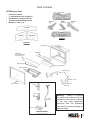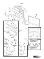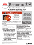
1
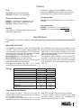
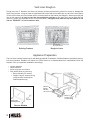
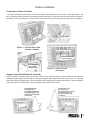
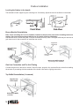
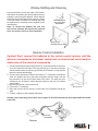
Patents Pending
Model RF24DN/DP
Direct Vent Fireplace Insert
Installation and Owner’s Manual
INSTALLER: Leave this manual with the appliance.
CONSUMER: Retain this manual for future reference.
Please read this manual BEFORE installing and operating this appliance.
WARNING: If the information in these
instructions is not followed exactly, a fire
or explosion may result causing property
damage, personal injury or loss of life.
This appliance may be installed in
an after-market permanently located,
manufactured (mobile) home where not
prohibited by local codes.
Do not store or use gasoline or other
flammable vapors and liquids in the
vicinity of this or any other appliance.
This appliance is only for use with the type
of gas indicated on the rating plate. This
appliance is not convertible for use with
other gases, unless a certified kit is used.
WHAT TO DO IF YOU SMELL GAS
• Do not try to light the appliance.
• Do not touch any electrical switch; do not
use any phone in your building.
• Immediately call your gas supplier from
a neighbor’s phone. Follow the gas
supplier’s instructions.
• If you cannot reach your gas supplier, call
the fire department.
Installation and service must be performed
by a qualified installer, service agency or
the gas supplier.
This appliance is a domestic room-heating
appliance. It must not be used for any
other purposes such as drying clothes,
etc.
This appliance is suitable for installation in
a bedroom or bed sitting room.
Massachusetts: The piping and final
gas connection must be performed by a
licensed plumber or gas fitter in the State
of Massachusetts.
Manufactured by
MILES INDUSTRIES LTD.
British Columbia, Canada
www.milesfireplaces.com
4000607-11
© 2007 Miles Industries Ltd. All rights reserved.
Thank You ...
For purchasing a Retrofire by Miles Industries. Your new radiant gas heater is a
technical appliance that must be installed by a qualified dealer. Each Retrofire is fully
tested during the production process for your safety and comfort.
Your unit has been professionally installed by:
Dealer Name _______________________________________
Phone Number ______________________________________
Should you encounter an operational problem, call your dealer immediately.
Do not try to repair the unit as you may cause an injury or damage the
fireplace.
The information contained in this installation manual is believed to be correct at the time of printing.
Miles Industries Ltd. reserves the right to change or modify any information or specifications without
notice. Miles Industries Ltd. grants no warranty, implied or stated, for the installation or maintenance
of your heater, and assumes no responsibility for any consequential damage(s).
We recommend that our gas
hearth products be installed
and serviced by professionals
who are certified in the
United States by NFI (National
Fireplace Institute®).
2
Contents
Safety and Warning Information...................................................................4
Options ...........................................................................................................5
Specifications ................................................................................................5
Dimensions ....................................................................................................6
Vent Configurations.......................................................................................7
Vent Termination ............................................................................................8
Pack Contents ................................................................................................9
Existing Fireplace Preparation ...................................................................10
Supply Gas ...................................................................................................11
Vent Liner Rough-In.....................................................................................12
Appliance Preparation.................................................................................12
Firebox Installation ......................................................................................13
Ceramic Fuel Bed Installation ....................................................................15
Window Refitting and Checking .................................................................17
Remote Control Installation ........................................................................17
Operation Check and Aeration Adjustment ..............................................18
Cast Iron Fret Installation ...........................................................................18
Owner’s Information ....................................................................................19
Lighting Instructions ...................................................................................22
Warranty .......................................................................................................23
Parts ..............................................................................................................24
3
Safety and Warning Information
READ and UNDERSTAND all instructions carefully
before starting the installation. FAILURE TO FOLLOW
these installation instructions may result in possible fire
hazard and will void the warranty.
Prior to the first firing of the fireplace, READ the Owner’s
Information section of this manual.
DO NOT USE this appliance if any part has been
under water. Immediately, CALL a qualified service
technician to inspect the unit and to replace any part of
the control system and any gas control that has been
under water.
THIS UNIT IS NOT FOR USE WITH SOLID FUEL.
Installation and repair should be PERFORMED by a
qualified service person. The appliance and venting
system should be INSPECTED before initial use and at
least annually by a professional service person. More
frequent cleaning may be required due to excessive
lint from carpeting, bedding, etc. It is IMPERATIVE that
the unit’s control compartment, burner, and circulating
air passageways BE KEPT CLEAN to provide for
adequate combustion and ventilation air.
Always KEEP the appliance clear and free from
combustible materials, gasoline, and other flammable
vapors and liquids.
NEVER OBSTRUCT the flow of combustion and
ventilation air. Keep the front of the appliance CLEAR
of all obstacles and materials for servicing and proper
operation.
Due to the high temperature, the appliance should be
LOCATED out of traffic areas and away from furniture
and draperies. Clothing or flammable material SHOULD
NOT BE PLACED on or near the appliance.
Children and adults should be ALERTED to the hazards
of high surface temperature and should STAY AWAY to
avoid burns or clothing ignition. Young children should
be CAREFULLY SUPERVISED when they are in the
same room as the appliance.
This gas fireplace and vent assembly MUST be
vented directly to the outside and MUST NEVER be
attached to a chimney serving a separate solid fuel
burning appliance. Each gas appliance MUST USE
a separate vent system. Common vent systems are
PROHIBITED.
INSPECT the external vent cap on a regular basis to
make sure that no debris, plants, trees, shrubs are
interfering with the air flow.
The glass door assembly MUST be in place and sealed
before the unit can be placed into safe operation.
DO NOT OPERATE this appliance with the glass door
removed, cracked, or broken. Replacement of the glass
door should be performed by a licensed or qualified
service person. DO NOT strike or slam the glass door.
The glass door assembly SHALL ONLY be replaced
as a complete unit, as supplied by the fireplace
manufacturer. NO SUBSTITUTE material may be
used.
DO NOT USE abrasive cleaners on the glass door
assembly. DO NOT ATTEMPT to clean the glass door
when it is hot.
TURN OFF the gas before servicing this appliance.
It is recommended that a qualified service technician
perform an appliance check-up at the beginning of
each heating season.
Any safety screen or guard removed for servicing MUST
BE REPLACED before operating this appliance.
DO NOT place furniture or any other combustible
household objects within 36” of the fireplace front.
BE CAREFUL not to put any decorating objects
sensitive to heat too close to the fireplace as it gets
very hot when operating.
DO NOT use this heater as a temporary source of heat
during construction.
This unit MUST be used with a vent system as described
in this installation manual. NO OTHER vent system or
components MAY BE USED.
NOTE: When operating your new fireplace for the first time, some vapors may be released due to the burning
of curing compounds used in the manufacture of the appliance. They may cause a slight odor and could cause
the flames to be the full height of the firebox, or even slightly higher, for the first few hours of operation. It is also
possible that these vapors could set off any smoke detection alarms in the immediate vicinity. These vapors are
quite normal on new appliances. We recommend opening a window to vent the room. After a few hours use, the
vapors will have disappeared and the flames will be at their normal height.
4
Options
Fuel
Termination—Miles Industries’ 559CLT Co-Linear
Termination. 559SFK Square Flashing Kit required for
terminating existing masonry chimney applications.
RF24DVN—Natural Gas Installations
RF24DVP—Propane Gas Installations
Circulating Fan
Decorative Cast Iron Frets
555CFK—Circulating Fan Kit with 6’–0” c/w grounded
cord set.
RA24CV—Contemporary, Vintage Iron Finish
RA24AV—Avant-Garde. Vintage Iron Finish
RA24TB—Traditional, Black Finish
Conversion Kits
Venting
RA24NK—to convert from LPG to Natural Gas
RA24PK—to convert from Natural Gas to LPG
Pipe—generic 3” diameter flexible aluminum liner
approved for gas venting.
Specifications
This appliance is intended for installation into existing masonry or factory-built, solid-fuel burning fireplaces
only.
Approvals and Codes
This appliance is certified to ANSI Z21.88-2007/CSA
2.33-2007 Vented Gas Fireplace Heater standard for
use in Canada and the USA and to CGA 2.17-N91 High
Altitude Standard in Canada. This appliance is for direct
vent installation terminating at the roof only.
Model RF24DVN is for use with Natural Gas only.
Model RF24DVP is for use with LPG only.
Conversion between fuels may only be done using the
approved conversion kits listed above.
This appliance complies with CGA P.4.1, Testing
method for measuring annual fireplace efficiencies.
Ratings
Model
Gas
Altitude (Ft.)
Input Max. (Btu/h)
Input Min. (Btu/h)
Manifold pressure (in w.c.)
Min. Supply pressure (in w.c.)
Max. Supply pressure (in w.c.)
Main Burner Injector
Catalogue Number (this is not a drill size)
Pilot Injector
Catalogue Number (this is not a drill size)
The installation must conform to local codes or, in the
absence of local codes with the National Fuel Gas Code,
ANSI Z223.1 or the Canadian Installation Code CAN/
CGA-B149. Only qualified licensed or trained personnel
should install this appliance.
This appliance, when installed , must be electrically
grounded in accordance with local codes, or in the
absence of local codes, with the National Electrical
Code, ANSI/NFPA 70 or the Canadian Electrical Code,
CSA C22.1
RF24DVN
RF24DVP
Natural
Propane
0-4,500 Feet*
24,000
24,000
10,500
10,500
3.95
9.5
5.0
11.0
10.5
14.0
Bray Cat.
Bray Cat.
#82-580
#92-260
S.I.T.
S.I.T.
#62
#30
*High Altitude Installations
Input ratings are shown in BTU per hour and are
certified without deration for elevations up to 4,500 feet
(1,370 m) above sea level.
For elevations above 4,500 feet (1,370 m) in USA,
installations must be in accordance with the current
ANSI Z223.1 and/or local codes having jurisdiction.
In Canada, please consult provincial and/or local
authorities having jurisdiction for installations at
elevations above 4,500 feet (1,370 m).
5
Dimensions
Dimensions
24-1/2”
8”
17-1/4”
3” dia.
Exh
3” dia.
Inlet
RA24TB Fret (Black)
25-1/2”
4-1/2”
11”
10”
Gas Inlet
3/8” NPT Female
Min. 12”
Max 14”
27”
RA24CV Fret (Vintage Iron)
RA24AV Fret (Vintage Iron)
Control Valve
Location
Optional Frets
Min. 12”
Max 14”
24”
Top View
3-1/4”
Fret
Mounting
Brackets
(removeable)
Gas Inlet
3/8” NPT Female
Optional
Cast
Fret
16-1/2”
18-3/4”
Adjustable
Convection
Baffle
19-1/4”
1”
Front Face of
Cast Fret
Optional Fan
Speed Control
Location
(this side at front)
1-3/4”
Control Valve
1-1/4”
12-1/2”
24”
Levelling
Feet
13-3/4”
Front View
Side View
Minimum Cavity Dimensions
The diagram shows minimum dimensions required to
install the RF24. Cavities having a combination of all the
minimum dimensions shown, although possible, may
prove to be difficult installations.
Height to Smoke Curtain
18”
19-1/2”
17”
14”
25-1/2”
Minimum Cavity
6
Vent Configurations
Allowable Vent Configurations
The RF24 is certified for use with approved 3” diameter flexible venting installed into an approved existing solid
fuel burning masonry or factory built chimney system. The venting system must terminate vertically at the roof
using an approved termination cap. Both inlet and exhaust liners must be run continuously from appliance to roof
termination. Where possible, avoid joints in flex pipe. If joints are required, use only connectors approved by the
manufacturer of the flex pipe. Field fabricated joints are not allowed.
Any generic 3” diameter flexible venting approved for venting gas appliances is acceptable.
559CLT
Co-Linear Terminal
10”
40’
10”
35’
25’
20’
15’
9’6”
10’0”
9’0”
8’6”
7’6”
8’0”
7’0”
6’0”
6’6”
5’0”
5’6”
10’
4’6”
Vertical Vent Height
559CLT
Termination
See
Chart
10’ min. - 40‘ max.
30’
3” Inlet & Exhaust
Collars (exhaust collar
is slighthly longer)
Allowable Horizontal Offset
3” Liners
3” min. Bend
Radius
7
Vent Termination
10” dia.
10”
7-5/8” dia.
559CLT
11”
The RF24 is approved for Vertical Co-Linear Termination Only. Two 3” diameter
liners are required from top to bottom. The vent liners must be connected to the proper
collars (intake and exhaust) or the unit will not operate properly. The method of flashing
will depend on whether the liners are installed into a rectangular masonry or round
factory-built solid-fuel burning chimney. It is important to seal the gap at the top
of the chimney in either case to avoid convective air loss up the chimney. The
integrity of the air-cooled function of factory-built chimney systems must be maintained
when installing terminations. Termination of the chimney may need to be completed
after the RF24 firebox is installed and the slack vent liner pulled up—see Section
Installing Firebox.
559CLT Terminal
Existing Square Chimneys
559CLT Co-Linear Terminal and 559SFK Square Flashing Kit are
required. Cut flashing kit to size. Allow extra around perimeter for drip
edge to be formed on site. Seal flashing to top of chimney using sealant
(not supplied). Fasten terminal to flashing using sheet metal screws as
shown.
559SFK Flashing
(cut to required
size and form
drip edge on site)
Fasten to Flashing
with Sheet Metal
Screws (3 locations)
2 - 3” Flex Liners
18
”
”
18
Existing Round Factory-Built Chimneys
The 559CLT terminal is designed to fit existing 7” or 8” diameter factory-built round chimneys without requiring
additional flashing. Ensure the installation of the terminal seals off the top of the chimney space to avoid convective
air loss. The diagrams below show a typical terminal installation for an 8” diameter air-cooled chimney system.
Remove Top
Portion of
Terminal
Maintain Air-Cooled
Function of Existing
Chimney System
Existing Air-Cooled Chimney
(Factory-Built Fireplaces)
559CLT Termination
Identify
which
Liner is
Exhaust
Fasten Terminal
to Flashing
(3 locations)
EXH
EXH.
Install 2 - 3” dia.
Flex Liners
8
Connect Liners to
Corresponding
Collar on Terminal
using Sheet Metal
Screws (longer
collar is exhaust
collar)
Ensure Flashing
Remains over
Air-Cooled
Openings
Ensure Exhaust
Portion of Chimney
is Sealed at Top
Pack Contents
RF24 Engine Pack
Rear Log
•
•
•
•
•
Content as shown
3” dia Stainless Gear Clamps (2)
Fret Retainer Thumbscrews (4)
Convection Baffle Wing nuts (2)
Batteries—4 AA, 1 9V
L/H Cross
Log
R/H Cross
Log
Middle
Cross Log
Rear Brick
Front Log
Left Brick
Right Brick
Log Set
Brick Set
Firebox Unit
Top Baffle
Adjustable
Convection Baffle
(packed loose)
Wingnuts (2)
Rear Log Support
Burner Module
Support Legs
Thumb Screws
Window Unit
Fret Retainer
Brackets
Handset
Handset
Wall
Holder
Wiring
Harness
Receiver
Warning : Failure to position
the parts in accordance with the
diagrams in this manual, or failure
to use only parts specifically
approved with this appliance
may result in property damage or
personal injury
Remote Control
9
Pack Contents
Optional Frets (sold separately)
Choice of cast iron frets available separately. Simply slide into place on fret retainers supplied with engine.
25-1/2”
27”
24-1/2”
RA24TB Fret (Black)
11”
10”
8”
RA24CV Fret (Vintage Iron)
RA24AV Fret (Vintage Iron)
555CFK Circulating Fan Kit (sold separately)
Thermally actuated fan (blower), mounting plate, and variable speed control complete with 6’–0” grounded cord
set. Complete instructions packaged with kit.
Conversion Kits (sold separately)
RA24NK to convert from LPG to Natural Gas.
RA24PK to convert from Natural Gas to LPG.
Kits include main burner orifice, pilot burner orifice, instructions, special screwdriver to access regulator.
Note: A manometer is required to reset pressure regulator on valve.
Existing Fireplace Preparation
A few points must be considered before inserting the RF24 into an existing fireplace cavity. Generally, no
modifications are allowed to the existing fireplace that will compromise the integrity of the existing fireplace.
Components that are bolted or screwed on such as dampers or baffles may be removed to accommodate the
installation of the RF24 engine. Cutting away any sheet metal parts of the existing fireplace to accommodate
the installation of the RF24 is prohibited. Check with local authorities if in doubt.
Clean Fireplace and Chimney
Have the chimney swept and the fireplace cavity cleaned before installing the RF24 heater and vent liners. Any
creosote or soot residue remaining in the fireplace cavity or chimney may cause odors once the RF24 insert is
installed. Consult with chimney sweep for information on how best to clean.
Existing Dampers
Factory-built, zero-clearance fireplaces will require the damper to be removed in order to install the vent liners.
These dampers are usually bolted into place. Dampers in masonry fireplaces must be fixed open and may remain
in place.
Ash Retaining Curbs
Some fireplaces (particularly factory-built) have a raised curb at the front edge to retain ashes. Check the dimensions
carefully to ensure the RF24 engine will fit behind any raised curb (some curbs may be removed separately from
the refractory base). The fret retainers allow for some vertical adjustment of the cast iron fret should the fret need
to sit on top of the curb, otherwise the fret will need to be eliminated or adequate room provided behind the curb.
Gas Line Routing
Plan the routing of the gas line before proceeding. Utilize the existing hole for the gas line. If the factory-built
fireplace has no access hole, carefully drill an access hole of 1.5 inch (38 mm) or less through the lower sides or
bottom of the firebox. The access hole must be plugged with non-combustible insulation after the gas supply line
has been installed. See General Dimension drawing for detailed location of gas inlet. Also, take into consideration
whether or not a fan or shut-off valve will interfere when planning routing of the gas line.
10
Existing Fireplace Preparation
Existing Glass Doors and Wire Screens
Existing glass doors must be permanently removed prior to installing the RF24 insert. Existing wire fire screens
may remain in place or new ones may be added. The RF24 has been tested and approved to operate with wire
fire screens in the closed or open positions.
Combustible Mantels
Combustible mantel clearances must conform to those required for the original solid-fuel fireplace into which the
RF24 is being installed.
Paint Existing Refractory Liners
It may be desirable, for visual reasons, to paint the existing refractory liners in black to blend in with the RF24
insert once installed.
Attach Warning Label to Existing Fireplace (label supplied loose with RF24 heater)
Attach the “This fireplace has been converted...” label to the existing fireplace using screws or other mechanical
means and store any removed parts in back of the existing fireplace for future use.
Supply Gas
•
•
•
•
•
•
•
•
•
•
•
•
•
•
•
It’s preferable to rough-in the gas line at this point before proceeding with the firebox installation.
The gas supply inlet connection is a 3/8” NPT female connector. For detailed location of this connector, see drawing
in section Dimensions. If a circulating fan or isolating valve is to be installed, adjust the routing of the gas line to
suit.
Use only new black iron or steel pipes or copper tubing if acceptable—check local codes. Note that in USA, copper
tubing must be internally tinned for protection against sulfur compounds.
Unions in gas lines should be of ground joint type.
The gas supply line must be sized and installed to provide a supply of gas sufficient to meet the maximum demand
of the appliance without undue loss of pressure.
Sealant used must be resistant to the action of all gas constituents including LP gas. Sealant should be applied
lightly to male threads to ensure excess sealant does not enter gas lines.
The supply line should include a manual shut-off valve and union to allow the appliance to be disconnected for
servicing.
Pressure test the supply line for leaks.
The appliance and its individual shut-off valve must be disconnected from the gas supply piping system during any
pressure testing of that system at test pressures in excess of ½ psig (3.5 kPa).
The appliance must be isolated from the gas supply piping system by closing its individual manual shut-off valve during
any pressure testing of the gas supply piping system at test pressures equal to or less than ½ psig (3.5 kPa).
Failure to either disconnect or isolate the appliance during pressure testing may result in regulator or valve damage.
Consult your dealer in this case.
The minimum supply pressure is given in the section Specifications of
this manual.
All piping and connections must be tested for leaks after installation or
servicing. All leaks must be corrected immediately.
Inlet Pipe
When testing for leaks:
• Make sure that the appliance is turned off.
• Open the manual shut-off valve.
• Test for leaks by applying a liquid detergent or soap solution to all
joints. Bubbles forming indicate a gas leak. Never use an open
Manifold Pressure
flame to check for leaks.
Test Tap
Supply Pressure
• Correct any leak detected immediately.
Test Tap
The pressure test tapping locations are shown in figure above. A built- Loosen screw to check
(tighten afterwards)
in non-adjustable regulator controls the burner manifold pressure. The
Pressure Test Tappings
correct pressure range is shown in the table in section Specifications of
this manual. The pressure check should be made with the burner alight
and at its highest setting. See lighting instruction section for full operating details.
11
Vent Liner Rough-in
EXH.
Rough-in the two 3” diameter vent liners into existing chimney system being careful not to tear or damage the
liners in the process. It may be easier to install both liners at the same time rather than one at a time. Leave plenty
of liner at the bottom end if the Heater will be connected while on the hearth (see diagram). When connecting the
liner in this manner it is best to leave the top termination until later so the slack liner can be lifted after the
insert is in place (see separate section for top termination). Designate and mark the top and bottom of one
liner as “EXHAUST” to avoid confusion later.
Two 3” dia.
Aluminum Liners
Existing Fireplace
Rough-In Liners
Appliance Preparation
The size of the existing fireplace cavity will affect the method of installation. Smaller fireplaces, particularly factorybuilt zero-clearance fireplaces will require the RF24 firebox to be disassembled then reassembled inside the
fireplace. Plan your particular installation accordingly.
•
•
•
Unpack appliance.
Remove window.
Remove log pack from firebox.
• Strip firebox down by removing:
• Burner Module (10 screws),
• Support Legs (2 screws per leg)
(required when inserting into
small fireplaces only)
Remove
Burner
Module
(10 screws)
Spring-loaded
Fastening Studs (2)
1/4 Turn
Remove Window
12
Remove
Support Legs
(2 screws/leg)
Firebox Installation
Connection of liners to firebox
Trim liners if necessary and connect to the firebox either while the firebox is on the hearth or with the firebox in the
cavity. Use gear clamps provided to connect the liners to the firebox. If the liners are connected with the firebox on
the hearth, it will be necessary to pull the slack liner up from the top of the chimney after the firebox is installed.
Gear Clamps
Option 1 - Connect liners with
Firebox on Hearth
Reach Through Front
to Connect Liners
Reach Through
Top or Sides
to Connect Liners
Option 2 - Connect Liners
in Fireplace
Support Legs Reinstallation (if removed)
With the firebox recessed behind the smoke curtain of the existing fireplace, raise the firebox and place the
individual support legs under the firebox. Placing a temporary shim under the firebox, such as a 2” x 4”, may help
while positioning the support legs. Tabs are provided on the support legs to help position them. Fasten the support
legs at the points indicated by the arrows using the bolts provided (2 per side).
Thread thumbscrews
into Support Leg.
Raise right side of firebox
and slip RH Support Leg
Under. Fasten with 2 bolts
as indicated.
Thread thumbscrews
into Support Leg.
Raise left hand side of firebox
and slip LH Support Leg
Under. Fasten with 2 bolts
as indicated.
13
Firebox Installation
Leveling the firebox in the hearth
The backside of each support leg has a leveling bolt. If necessary, adjust the level of the firebox in the hearth.
Fret bracket
Leveling
bolt
Leveling
bolt
Leg
Front
Back
Leveling bolt
Front View
Side View
Burner Module Reinstallation
Note: If the circulating fan is to be installed it should be done at this point before installing the burner
module. See instructions packaged with the fan for details of the fan installation.
Reinstall the burner module using the 10 screws removed previously. Note: The upper baffle may be removed to
gain more room for the screwdriver to install the rear screws.
Edge Fits Into
Cleat at Back
Reinstall Burner
Module
(10 screws)
Remove Top Baffle
(2 screws)
Remove Top Baffle (optional)
(to provide space for a screwdriver)
Gas Line Connection and Fire Unit Testing
Connect the gas line to the burner module. Check for leaks, purge the line, and test-fire the unit before installing
the window or proceeding with the remainder of the install—see section Lighting Instructions.
Top Baffle Reinstallation (if removed)
Edge Fits Into
Cleat at Back
Reinstall Top Baffle
(2 screws)
14
Firebox Installation
Top Convection Baffle Installation
Position the firebox as far back as possible within the existing fireplace to allow ample space at front for the fret
and to allow convection air to flow under the smoke curtain of the existing fireplace. Position the top convection
baffle with the threaded studs pointing downwards into the slots at the top of the firebox. Slide the convection
baffle as far forward as possible, angled down if possible, to force the air under the smoke curtain, and tighten
the wing nuts.
Co
nve
ct
ion
Start wingnuts on studs. Slide
Convection Baffle into slots.
Adjust Baffle Forward to Touch
Back of Smoke Curtain of
Existing Fireplace. Tighten
Wingnuts.
Ba
ffle
Wingnuts (2)
Ceramic Fuel Bed Installation
Ceramic Brick Liner Installation
Install the ceramic brick liner taking care not to damage them as the material is fragile. The top rounded edges of
the side panels should face inwards and the front edge bevelled. Place the side brick panels flat against the side
of the firebox up high and slide downward into place behind the front return edge on the firebox.
Rear Brick
Rest Brick on
Rear Log Support
Side Brick in front of Rear Brick
Rear Brick
Left
Brick
Rear Brick
Left
Brick
Right
Brick
Side Brick Behind
Firebox Return
15
Ceramic Fuel Bed Installation
Ceramic Log Set Installation
Carefully remove the ceramic logs from the packaging taking care not to damage them. Install the logs as described
below. Please note that the Rear Log will have a different position depending of the gas type. The position
of the logs is critical to insure the good performance of the appliance.
NG ONLY: Drop Rear Log into place
behind front log retainers.
Rear Log Touches
Front Log Here
LPG ONLY:
Drop Rear Log into
place centered sideto-side against back
support so the log
sits more vertical.
1
Front Log locating pins
Right Log
Locating Pins
2
Place Font Log onto locating
Pins at Each End
L/H Log Locating Pins
Place R/H Cross Log
Onto Locating Pins
3
4
Place L/H Cross Log
Onto Locating Pins
5
16
Place Middle Cross Log
Across Gap in Front Log
Window Refitting and Checking
Hook the window over the top edge of the firebox,
and fasten the bottom two spring loaded bolts by
pushing in and turning 90 degrees. Check that the
window moves freely against the spring by pulling
out at the bottom. If broken, the window may only
be replaced as a complete unit as supplied by the
manufacturer.
Note: To remove the window, the cast iron
fret and fret retainers will need to be removed
first—see section Cast Iron Fret Installation.
Check that Window
Moves Freely After
Reinstallation
Spring Loaded
Fastening Studs (2)
1/4 Turn
Remote Control Installation
Caution! Don’t connect the batteries to the remote control receiver until the
wires are connected to the burner control unit, as short-circuit could result in
destruction of the electrical components.
1. Connect the wiring harness to the receiver box, by pushing the wire connector
on to the receiver circuit board. The plug will only go on one way so please
ensure that the wires are pointing up and slot in the board is in line with the
tab on the wiring harness plug.
2. Connect wires as shown. Please note that the “L” connectors are different
sizes, the smaller one fits to the lower connection and the larger one the
top connection on the top left hand side of the valve. The other two wire
connectors can be fitted to either terminal located to the left of the flame
control button.
3. Remove the remote control receiver lid.
4. Fit four AA 1.5 V batteries.
5. Place the remote control receiver on the base of the fireplace beside the
valve.
6. Fit the 9 V battery to the handset transmitter.
Remote Receiver
Remote control operating instructions are on pages 19–20 of this manual and are supplied with the remote
control kit.
Push-on
Connector
Receiver
Valve
17
Operation Check and Aeration Adjustment
Turn the fireplace up and down using the remote control to confirm that
the full range of inputs is achieved.
Light the fire and allow to warm up for 10–15 minutes to evaluate the
flame picture. The burner is equipped with an adjustable air shutter to
control primary aeration. See figures below. The shutter is factory-set
at an aeration gap, which will give optimum performance for the vast
majority of installations. In a few unusual installations, flame picture may
be improved by adjusting the aeration. The need for adjustment should be
determined only by operating the appliance with the ceramic fuel effects
and window installed.
Increasing aeration will cause the flame to appear more transparent and
blue making the ceramic fuel effects glow more.
Decreasing aeration will
cause the flames to appear
more yellow or orange
making the fuel effects glow
less.
Too little aeration may
result in black carbon
Air Shutter in
forming and dropping
Open Position
into the firebox.
Air Shutter
Air Shutter Retainer
Air Shutter Components
Air Shutter in
Closed Position
Cast Iron Fret Installation
Note: The fret retainer brackets are designed to maintain
the required space in front of the window to allow the
window to move and relieve during a hard start. It is very
important to ensure this area in front of the window
is kept clear at all times.
Fret Retainer Brackets Installation
Screw 2 thumbscrews into sides of each support leg if not
done previously when support legs were installed. Fit the
slotted holes in the fret retainers over the thumbscrews,
push fret retainers downwards and tighten screws.
Slip Fret Retainer
over thumbscrews
and tighten screws
Drop Fret with Bolt
into Slotted Retainer
(fret adjusts up or down
to suit)
Cast Iron Fret Installation
Adjust screw heads on back of fret to the thickness of
the retainer bracket and drop the fret into place while
guiding the screw heads into the slots in the bracket.
Clip the ash pan cover onto the fret.
18
Owner’s Information
Please read the Safety and Warning Information section at the beginning of this manual.
Operating Your Fire
For your safety, this appliance is fitted with a flame supervision device which will shut-off the gas supply if, for
any reason, the pilot flame goes out. This device incorporates a fixed probe, which senses the heat from the pilot
flame. If the probe is cool, the device will prevent any gas flow unless the burner control knob is kept pushed in at
the PILOT position. See full lighting instructions on page 22 of this manual.
Programmable Remote Control
Your fireplace remote control helps you get the comfort, convenience and
aesthetics you want from your gas fireplace. The remote controls your fireplace
in different ways.
IMPORTANT: BEFORE YOU BEGIN, please note that on this system,
the settings of time, temperature and automatic ON/OFF can only be
programmed when the function display is flashing. Be patient when
programming as it can take a few seconds to set.
Setting the Time
The first thing to do is to set the time.
1. With your thumb, hold down both the AUTO and TIMER buttons until F flashes.
Let go.
2. Note the digital clock on the bottom right hand corner. The ▲
button sets the hour; the ▼ button sets the minutes. Set the time.
Note: You must start setting the time while the F is flashing. If it stops flashing,
go back to 1.
3. The display shows °C/24-hour or °F/12-hour. To change the temperature/hour
display, press on the AUTO button while the display flashes.
4. Let go and wait until the flashing stops. The remote shows the time you set. It
also shows the current temperature.
Setting the Temperature
Use this setting when you come in and want to enjoy a specific temperature.
1. Push the AUTO button until a number and F flash. Let go.
2. While it is still flashing, push the ▲ and ▼ buttons to the temperature you
want. Let go.
Your fireplace will reach that temperature and the remote will check the temperature
every five minutes, adjusting the amount of fuel needed to give you a steady, even
heat.
Setting the Flame
Use this setting when you want a particular flame level. For instance, you want to
watch flames burn at their highest level and you don’t mind if the room is too hot.
1. To raise the flame, press and hold the ▲ button until the flame gets to the
desired level. Let go.
2. To lower the flame, press and hold the ▼ button until the flame gets to the
desired level. Let go.
The flame level will remain just as you set it.
19
Owner’s Information
Automatic ON/OFF
You can set your fireplace to come on before you wake up and turn off after you
leave and then, turn on again just before you come home and turn off after going
to bed.
You can leave it like this for the heating season.
1. Decide what temperature you want your fireplace to be at. Also, decide what
time you want your fireplace to turn on and off. Finally, decide what time you
want it to come back on and off in the afternoon or evening. For the first few
times you set the timer, it’s handy to write these times down.
2. Set the temperature (just as you did in the section Setting the Temperature.)
3. Press the TIMER button and hold it until P1 ☼ appears and flashes. Let go.
While flashing, push the buttons▲ (hour) and ▼ (minutes) to set the time at
which you want your fireplace to turn on in the morning.
4. Press the TIMER button and hold it until P1 ☽ appears and flashes. Let go.
While flashing, push the buttons ▲ (hour) and ▼ (minutes) to set the time at
which you want your fireplace to turn off when you leave.
5. Press the TIMER button and hold it until P2 ☼ appears and flashes. Let go.
While flashing, push the buttons ▲ (hour) and ▼ (minutes) to set the time at
which you want your fireplace will turn back on in the afternoon.
6. Press the TIMER button and hold it until P2 ☽ appears and flashes. Let go.
While flashing, push the buttons ▲ (hour) and ▼ (minutes) to set the time at
which you want your fireplace to turn off in the evening.
Note: If you want to set your fireplace for only one time on and off, set P2 ☼ and
P2 ☽ for the same times as P1 ☽. The remote will record the P1 ☽ off time for
both P2 times.
To temporarily override the timer setting, just press AUTO or ▲ and ▼ to go back
to manual settings. Press TIMER to go back to your settings.
When your remote control displays BATT, you need to replace the battery with a
new 9 volt alkaline battery—6LR61/MN1604.
20
Owner’s Information
Cleaning
It will be necessary to clean the glass periodically. During startup,
condensation, which is normal, forms on the inside of the glass and causes
dust, lint etc. to cling to the glass surface. Initially paint, while curing, may
Check that Window
Moves Freely After
deposit a slight film on the glass. We therefore recommend that, during
Reinstallation
the first few weeks of use, the glass be cleaned two or three times with
non-abrasive common household cleaners and warm water. Ammonia
based cleaners should not be used. Subsequently, the glass should be
cleaned two or three times a season depending on the circumstances.
Do not clean the glass while it is hot. Always securely replace the window
1/4 Turn
before lighting. If broken, the glass pane may only be replaced as a
Spring Loaded
Fastening Studs (2)
complete window unit as supplied by the manufacturer.
It is necessary to remove the cast iron fret and brackets before
removing the window—see section Cast Iron Fret Installation).
The window can be removed for cleaning by rotating the two fastening studs at the bottom corners
90 degrees to release, and swinging the bottom of the window unit outwards to unhook the top edge.
After refitting the window, apply light hand pressure against the window frame sides to bed-in the window seal.
Dust, etc. can be brushed from the ceramic fuel effects and firebox walls after removing the front unit and opening
the window. Dust etc. can also be removed from the burner using a soft brush after removing the ceramic fuel
effects. When cleaning, make sure that no particles are brushed into the slots in the burner.
Checks
Performance of LPG appliances may be affected by the quality
of commercial gas supplied in your area.
Pilot Flame
A periodic check of the pilot and burner flames should be made. Check after the
fire has been on for at least 30 minutes. The pilot flame must cover the tip of
the thermocouple probe. The main burner flame pattern will vary from appliance
to appliance depending on the type of installation and climatic conditions—see
figures at right.
The appliance area must always be kept clear and free from combustible
materials, gasoline and other flammable vapors and liquids.
Inspect the vent terminal outdoors regularly to make sure that, snow,
leaves, bushes, trees, etc, do not obstruct it.
Examine the vent system and terminal regularly. We recommend
annually.
Thermocouple
Probe must be
in Flame
Batteries Replacement
All appliances use four 1.5 V AA batteries for remote control receivers
and the handset uses a 9 V battery.
Correct Flame Picture
Batteries are accessible by removing the lid of the remote control
receiver. Batteries should last one to two seasons, depending on
usage. Removing batteries in the off season will extend battery life. Should the batteries loose power, the control
may be operated by manually turning the control knob at the valve.
General Servicing
If your appliance needs to be serviced, contact your supplier quoting the model number. It will be helpful if the
appliance serial number can also be quoted. This is on the rating plate, which is attached to the unit.
The repair parts are shown in the repair parts list. Please always quote the part number and description when
requesting spare parts.
21
Lighting Instructions
FOR YOUR SAFETY READ BEFORE LIGHTING
WARNING: If you do not follow these instructions exactly, a fire or explosion may result causing
property damage, personal injury or loss of life.
A. This appliance has a pilot, which must be lighted by hand. When lighting the pilot, follow these
instructions exactly. To save energy, turn the pilot off when not using the appliance.
B. BEFORE LIGHTING smell all around the appliance area for gas. Be sure to smell next to the floor
because some gas is heavier than air and will settle on the floor.
WHAT TO DO IF YOU SMELL GAS
•
Do not try to light any appliance.
•
Do not touch any electric switch; do not use any phone in your building.
•
Immediately call your gas supplier from a neighbor’s phone. Follow the gas supplier’s
instructions.
•
If you cannot reach your gas supplier, call the fire department.
C. Use only your hand to push in or turn the control knobs. Never use tools. If the controls will not
push in or turn by hand, don’t try to repair them, call a qualified service technician. Force or
attempted repair may result in a fire or explosion.
D. Do not use this appliance if any part has been under water. Immediately call a qualified service
technician to inspect the appliance and to replace any part of the control system and any gas
control, which has been under water.
LIGHTING INSTRUCTIONS
1. STOP! Read the safety information above.
2. Set the flame adjustment knob as far
as possible*.
clockwise
to OFF.
3. Turn the gas control knob clockwise
NOTE: The knob cannot be turned from PILOT to
OFF unless it is pushed in partially. Do not force.
4. Wait five (5) minutes to clear out any gas, then
smell for gas, including near the floor. If you
smell gas, STOP! Follow “B” in the safety
information above. If you don’t smell gas, go to
the next step.
5. Find the pilot. It is at the left side of the firebox
viewed through slotted hole in front log.
6. Push in and turn the gas control knob counterclockwise until resistance is felt just before the
“IGN” position.
7. Keep pushed in for a few seconds to allow gas to flow then, keeping knob depressed, turn to
“PILOT” to light pilot. Hold knob in for a further 5 seconds then release. The knob should pop
back out. Pilot should remain lit. If pilot goes out repeat steps 3 through 7.
· If knob does not pop out when released, stop and immediately call your service technician or
gas supplier.
· If pilot lights but will not stay lit after several tries, turn the gas control knob to “OFF” and call
your service technician or gas supplier.
8. When pilot is lit, partially depress the knob and turn to “ON” position (Burner alight).
· Do not leave knob set between “PILOT” and “ON”.
9. Set the flame height to desired setting*.
TO TURN OFF GAS TO APPLIANCE
1. Set the flame adjustment knob as far clockwise
as possible*
2. Push in gas control knob slightly and turn clockwise
to “OFF”. Do not force.
* The flame height can be increased or decreased by depressing the remote control hand set
button.
22
Warranty
If you have a problem with this unit, please contact your dealer or supplier immediately. Under no
circumstances should you attempt to service the unit in any way by yourself. The warranties in paragraphs
1 and 2 are provided only to the first purchaser/user of this unit, are not transferable and are subject to the
conditions and limitations in paragraphs 3, 4 and 5. Please review the conditions and limitations carefully
and strictly follow their requirements.
1. Extended Warranty Coverage
For a period of up to ten (10) years, Miles Industries Ltd., (the “Company”) or its appointed distributor will at its option pay the
initial purchaser for the repair of, or will exchange the following parts or components which are found to be defective in material or
workmanship under normal conditions of use and service:
Part or Component
Exterior steel casing
Defect Covered
Corrosion
Maximum Warranty Period
10 years
Glass
Loss of structural integrity
10 years
Cast iron parts
Corrosion
10 years
Firebox and heat exchanger
Corrosion (but not discoloration) causing
loss of structural integrity
10 years
2. Two-Year Parts Warranty
In addition, for two (2) years from the date of purchase, the Company, at its option, can repair or exchange all parts and
components not listed above but that are found to have a bona fide defect in material or workmanship under normal conditions of
use.
3. Conditions and Limitations
a) The warranty registration card must be completed by the initial owner and returned to the Company within 90 days of purchase.
b) Installation and maintenance must be performed by an authorized and trained dealer in accordance with the Company’s
installation instructions.
c) This warranty is void where installation of the unit does not conform to all applicable codes including national and local gas
appliance installation codes and building and fire codes.
d) The owner must comply with all operating instructions.
e) The Company is not responsible for the labor costs to remove defective parts or re-install repaired or replacement parts.
f) The first purchaser or user of the unit will be responsible for any shipping charges for replacement parts as well as travel time
incurred by the dealer to perform the warranty work.
g) This warranty applies to non-commercial use and service and is void if it is apparent that there is abuse, misuse, alteration,
improper installation, accident or lack of maintenance to the unit.
h) This warranty does not cover damage to the unit through:
i)
Improper installation, operational or environmental conditions.
ii) Inadequate ventilation in the area or competition for air from other household equipment or appliances.
iii) Damage due to chemicals, dampness, condensation, or sulphur in the fuel supply lines which exceeds industry
standards.
i) This warranty does not cover glass, log breakage or damage to the unit while in transit.
j) The Company does not allow anyone to extend, alter or modify this warranty and assumes no responsibility for direct, indirect
or consequential damages caused by the unit. State or provincial laws where the first purchaser or user resides may provide
specific rights to extend this warranty and, if so, the Company’s sole obligation under this warranty is to provide labor and/or
materials in accordance with those laws.
4. Discharge of Liability
After two (2) years from the date of purchase, the Company may, at its option, fully discharge all obligations under this warranty by
paying to the first purchaser/user the wholesale price of any defective parts.
5. No Other Warranty
All obligations to repair this unit are defined in this warranty. Some states or provinces may specifically mandate additional
warranties on the part of manufacturers, but in the absence of such specific legislation, there is no other warranty or obligation
expressed or implied.
23
Parts
KEY
DESCRIPTION
1
Firebox Assembly
2
Restrictor (2)
3
Convection Baffle
4
Fret Support LH
5
Wing Nut (2)
6
Leg LH
7
Leveling Bolt (2)
8a
Log Support NG
8b
Log Support LPG
9
Leg RH
10
Fret Support RH
11
Thumbscrew # 10-32x1/2” (4)
12a
Burner Tray Assy DV, NG
12b
Burner Tray Assy DV, LPG
13
Airshutter
14a
Injector Elbow NG 82-580
14b
Injector Elbow LP 92-260
15
Valve Tray, DV
16
Gasket Rear
17
Gasket LH Side
18
Gasket Front
19
Gasket RH Side
20
Burner Support
21
Burner
22
Shutter Slider
23
Front Log Bracket
24
Olive 8mm
25
Olive Nut
26
Pipe Valve to main Burner
27
Tube Nut
28
Valve Mount
29a
190 Series Pilot Assy NG
29b
190 Series Pilot Assy LPG
30
Electrode Nut
31
Pilot Gasket
32
Pilot Bracket 190 Series
Threaded Plug Pilot Bracket
33
Thermocouple
34a
NG Pilot Injector #62
34b
LPG Pilot Injector #30
24
PART
NUMBER
400634AH
400767
4000744
4000693
4000741
4000662
4000242
4000621
4001456
4000663
4000694
4000753
4000635
4000653
4000657
720A580
9730007
4000714
4000642
4000643
4000641
4000644
4000579
4000599
4000759
4000739
519779
523389
4000600
523389
4000141
4000727
4000728
720A200
4000715
4000729
4000726
4000061
4001352
4000736
KEY
DESCRIPTION
35
2-Flame Pilot Hood
36
Electrode
37
Pilot Tube
38
Straight Connector
39
Maxitrol Valve GV34
Valve Cover
Servo Motor
PART
NUMBER
4000730
720A543
4000732
544079
4000056
4000801
4000802
40a
Minimum Rate Screw #160,
NG
4000810
40b
Minimum Rate Screw # 105,
LPG
4000824
41
Inlet Connector
4000746
42
Ignition Wire
43
Remote Control Kit
44
Transmitter
N/A
45
Receiver
N/A
46
Wall Bracket
N/A
47
Wiring Harness
N/A
48
Window Assy
4000604
49
Brick Set, Retrofire
4000648
50
Brick Panel, Rear
4000666
51
Brick Panel, LH
4000668
52
Brick Panel, RH
4000667
53a
Log Set, Retrofire NG
4000603
53b
Log Set Retrofire LPG
4000603P
54a
Rear Log NG
4000688
54b
Rear Log LPG
4000688P
55
RH Log
4000691
56
Centre Log
4000689
57
Front Log
4000692
58
LH Log
4000690
N/A
4000754
Parts
3
4
5
1
2
48
7
9
6
8a, 8b
10
23
22
21
11
13
14a,
14b
20
12a, 12b
15
19
50
49
16
17
18
51
28
35
53a, 53b
24
25
34a,
34b
27
32
31
36
33
30
26
29a, 29b
52
54a, 54b
58
43
55
44
56
37
45
42
41
40a, 40b
57
47
38
39
46
25