1
StarGate
20
REGULATORY
FCC INFORMATION
WARNING
TO PREVENT FIRE OR SHOCK HAZARDS, DO NOT EXPOSE THIS UNIT TO RAIN OR
MOISTURE. ALSO, DO NOT USE THIS UNIT’S POLARIZED AS PLUG WITH AN EXTENSION
CORD RECEPTACLE OR OTHER OUTLETS UNLESS ALL THREE PRONGS CAN BE FULLY
INSERTED
1. Use the power
and video cables
supplied with the
product to help
prevent interference
with radio and television reception. The
use of cables and
adapters may cause
interference with
electronic equipment
in the vicinity of this
unit.
2. Changes or modifi cations not expressly
approved by Z Microsystems could void
user’s warranty.
StarGate
20
CAUTION
RISK OF ELECTRIC SHOCK - DO NOT OPEN
CAUTION: TO REDUCE THE RISK OF ELECTRIC SHOCK DO NOT REMOVE COVER (OR
BACK OF UNIT). NO USER SERVICEABLE PARTS INSIDE. REFER SERVICING TO QUALIFIED PERSONNEL.
This symbol warns the user that insulated voltage within the unit may have sufficient
magnitude to cause electric shock. Therefore, it is dangerous to make any kind of
contact with any part inside this unit.
This symbol alerts the user that important literature concerning the operation and
maintenance of this unit has been included. Therefore it should be read carefully in
order to avoid any problems.
2
Doc# 27-0027UM Rev 1.0 Issued 10/04
TABLE OF CONTENTS
SECTION
PAGE
Introduction ........................................................................................................................4
About This Manual ....................................................................................................4
Safety Precautions....................................................................................................4
Product Description ..................................................................................................5
Installation Instructions .......................................................................................................6
Shipment Contents ...................................................................................................6
Required Tool ............................................................................................................6
Preparations ..............................................................................................................6
Hardware Installation ................................................................................................7
Cable Connections .................................................................................................10
Operations....................................................................................................................... 11
Power Up ................................................................................................................ 11
Display Panel Controls ...........................................................................................12
Display Panel Setup ................................................................................................13
Onscreen Menus.....................................................................................................14
SoftMenus ...............................................................................................................22
Maintenance ...................................................................................................................32
Troubleshooting ..............................................................................................................33
No Main Display Image ...........................................................................................33
No Picture-in-Picture Option Appears on Main Menu............................................34
No Picture-in-Picture Display Image ......................................................................34
Display Image Has Vertical Bars ............................................................................35
Display Image Appears Fuzzy ................................................................................35
Power Light Does Not Illuminate ............................................................................35
Schematics .....................................................................................................................36
Mechanical Outline for StarGate ............................................................................36
Mechanical Outline for StarGate ............................................................................37
Replacements .................................................................................................................38
Appendix .........................................................................................................................39
Specifications for StarGate ....................................................................................39
Warranties .............................................................................................................. 41
Customer Support ...................................................................................................47
Customer Feedback................................................................................................48
StarGate Serial Control ICD ...................................................................................49
3
Doc# 27-0027UM Rev 1.0 Issued 10/04
INTRODUCTION
ABOUT MANUAL
This Manual is also available on the Z Microsystems website (www.zmicro.com). We
recommend you read this manual carefully and follow the instructions in the Installation
chapter for verification of system functions and control settings.
The StarGate has an optional Touch Screen operation. Refer to the ELO touch screen CD
(user manual on the CD) when installing the StarGate.
Safety Precautions
DANGER:
To avoid shock hazard:
• Do not remove the covers around the
StarGate
• Do not connect or disconnect the
StarGate during an electrical storm.
• The power cord plug must be connected
to a properly wired and grounded
power outlet.
• Any equipment to which the StarGate
will be attached must also be connected
to properly wired and grounded power
outlets.
4
Doc# 27-0027UM Rev 1.0 Issued 10/04
INTRODUCTION
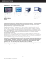
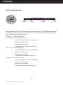
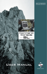
PRODUCT DESCRIPTION
The rugged lightweight StarGate
offers MIL-tailored
high-end liquid
crystal displays
(LCD’s) that can
adapt to specific
needs.
Quick release
levers allow it to
swing open.
Dual locks hold the
StarGate firmly in
the viewing position.
The StarGate can
be opened all the
way for access to
storage items and
other sensitive
equipment.
A StarGate is built to easily withstand harsh environmental conditions. Automatic Phase
Adjust functions lock to drifting graphic generator clocks and the Triple Frame Buffer
allows a wide range of input signal refresh rates.
The StarGate is only 5.5” deep and 15.75” (9U) in height. It attaches to the front of
RETMA rails in standard 19” racks and transit cases and requires no space inside the
rack. Dual locks hold the StarGate firmly in the viewing position. Quick release levers
allow it to swing open for access to storage items and other sensitive equipment behind.
The rugged, light weight design of the StarGate will stand up to the most extreme
environmental conditions.
Available in 20” active display areas, featuring up to 1600 x 1200 pixel resolution, the
StarGate offers an additional PIP option to help with equipment reduction in workspaces.
StarGate displays plug-and-play with any workstation, PC or X-Terminal and with activematrix LCD technology it provides astounding color and clarity.
Packaged in a lightweight aluminum enclosure, the StarGate target application platforms
include airplanes, helicopters, surface ships, submarines, vehicles and mobile shelters.
The StarGate features front control panel, an optional user replaceable safety glass
protective lens, and low power usage extends the life of the display.
The packaging and design of the electronics minimizes its susceptibility and emmissions
of electromagnetic interference.
5
Doc# 27-0027UM Rev 1.0 Issued 10/04
INSTALLATION
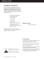
SHIPMENT CONTENTS
Ensure all of the following parts are included in the package received from Z Microsystems. Verify all parts have not been
damaged during shipment. If any of the
parts are missing or damaged, immediately
contact Z Microsystems Customer Service
at 858-657-1000.
• StarGate unit attached to
the mounting plate
• Power Cable
• User Manual
• Video Cable
• Serial Cable
Required Tools
• Rack-mounting hardware
• ELO Software CD for
optional Touch Screen (user
manual on CD)
• Phillips screwdriver
Remember to save the unit’s original
shipping materials. It may be necessary to
move the unit at a later date.
Preparations
In preparation to install the StarGate, take
the following precautionary steps:
Verify the StarGate power switch is OFF.
Do not connect or disconnect the unit during an electrical storm.
The power cord plug must be connected to
a properly grounded power outlet.
NOTE: For the fastest and easiest
installation of the StarGate,
follow these steps in the
sequence they are presented.
Any equipment to which the unit will be attached must also be connected to properly
wired and grounded power outlets.
6
Doc# 27-0027UM Rev 1.0 Issued 10/04
INSTALLATION
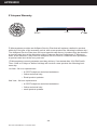
HARDWARE INSTALLATION
The StarGate is a flat LCD
that mounts on the front
of the RETMA rails of a
standard 19” rack.
The dual locks can be
seen on the vertical handle
to the left. The display
controls are located on the
bottom below the display.
On the center left side of
the back is the receptacle
for the power plug for the
cord that leads from the
power supply to the display, as well as the video
connector and host serial
connector.
The StarGate display
swings out to the right.
The bracket that mounts
to the front of the RETMA
rails is on the left.
On the top and bottom of
the mounting bracket is
the receptacle for securing
the display flat against the
rack.
7
Doc# 27-0027UM Rev 1.0 Issued 10/04
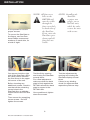
Using both hands, press
and slide the lock releases
inside the handle on the
left side of the display
towards each other to
release the locks and allow
you to swing open the
StarGate.
INSTALLATION
It is important to use the
proper screws.
To secure the StarGate to
the frame, use four Panhead Phillips screws and
washers on each side, for
a total of eight.
One person hold the right
side of the StarGate, while
the other person secures
the first screw in the upper
left corner of the unit.
Before inserting any
additional screws, check to
see that all the remaining
seven holes in the
StarGate line up with the
screw holes in the RETMA
rails.
NOTE: All four screw
holes in the
RETMA rail
must be visible
through the
four screw holes
on both sides of
the StarGate.
If not, move the
StarGate up or
down until all
four holes are
visible.
NOTE: Installing the
StarGate
requires two
people, one to
hold the unit,
while the other
secures the unit
with screws.
Test the fit by opening
and closing the StarGate
several times.
Test the adjustment by
opening and closing the
StarGate display several
times.
For a final adjustment,
make sure that the back
plate is flush against the
RETMA rail and the back
plate is square to the
RETMA rails.
Once positioned, tighten
down the screws.
Then secure the remaining
seven screws. Do NOT
tighten the screws.
8
Doc# 27-0027UM Rev 1.0 Issued 10/04
If there is any binding,
check for alignment and
repeat the previous step.
INSTALLATION
The display protective lens is intended to protect the surface of the screen from damage
while in transit or during storage. The protective lens is not intended to be used while the
StarGate is in operation, but can be used to protect the display if desired.
Make sure the StarGate is
in the closed position.
Move the protective lens
release catch (located
above the display) up.
While holding up the
release catch, slide the
protective lens to the left
or right.
9
Doc# 27-0027UM Rev 1.0 Issued 10/04
Slide the protective lens
off the edge of the display.
To reinstall the display protector during long storage
or shipping, just reverse
this process.
INSTALLATION
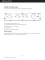
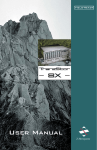
CABLE CONNECTIONS
The connections panel may vary due to non-standard configurations.
J4: DC PWR IN
J1: CH A
J2: HOST
J3: TOUCH
J1= Channel A (primary video feed)
J2= Host (Serial RS232 Connector to Main Controller)
J3= Optional Touch Screen Feature
J4= DC Power In
J5 (not shown)= Optional PIP Card
Panel Options
Either a RGB or NTSC PIP card can be installed in the option panel locations. All cabling
configurations are specific to the chosen panel option.
10
Doc# 27-0027UM Rev 1.0 Issued 10/04
OPERATIONS
POWER UP
When the StarGate is connected, apply power and ensure the main screen appears. If
the display does not turn on within ten seconds, press the Standby button on the display
panel upon completion of cabling. If the main screen does not appear after hardware and
cabling installations are complete, consult the Troubleshooting section of this manual.
11
Doc# 27-0027UM Rev 1.0 Issued 10/04
OPERATIONS
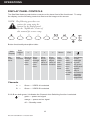
DISPLAY PANEL CONTROLS
The StarGate features push-button controls on the lower front of the front bezel. To setup
the display, use the following controls to fine tune the image on the screen:
NOTE: The following procedures are
written for setup using the
buttons on the display panel.
See the “SoftMenus” section of
this manual for remote setup.
Button functionality description table:
>
Key
Functions
Auto
Adjust
“Z”
<
>
Move
down
through
menu
functions
Move
left to
adjust
value of
function
Move
right to
adjust
value of
function
<
Main
Display
Auto
Move up
Position through
menu
functions
Menu
Activates
menu
and
menu
functions
Exit
Exit
from
main
menu or
return
from
submenu
to main
menu
Hold down
to turn
backlight
on and
off; press
briefly and
repeatedly to
increase or
decrease
backlight
brightness
Channels
A —
Green — VIDEO A is selected
B —
Green — VIDEO B is selected
If A & B are both green, it indicates the Channel Auto Switching function is selected.
—
green — power and signal
orange — power and no signal
off — Standby mode
12
Doc# 27-0027UM Rev 1.0 Issued 10/04
OPERATIONS
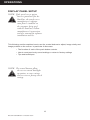
DISPLAY PANEL SETUP
NOTE: If the touch screen option
has been purchased for the
StarGate, the touch screen
manufacturer’s software
must first be installed on
the computer being used
with the StarGate. Follow
manufacturer’s instructions
and user manual for software
installation and use.
This following section explains how to use the control buttons to adjust, image clarity and
image position on the screen. In particular it discusses:
• The function of each of the push-button controls
• How to reset previously saved settings or return to factory settings
• Tips and techniques
NOTE: The control buttons allow
the user to control backlight
operations; to store settings,
and to revert to factory-saved
settings.
13
Doc# 27-0027UM Rev 1.0 Issued 10/04
OPERATIONS
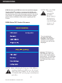
ONSCREEN MENUS
NOTE: When the unit is initially connected, no PIP
screens are enabled, and therefore can not
appear. See section titled “PIP configuration”
for how to enable PIP screens.
To access the onscreen
display main menu, press
the menu button on the
front of the panel. The
StarGate’s functions are
controlled using the Main
Menu’s subtopics.
These submenus can be
accessed using the Up
and Down buttons on the
display panel. See sections
below for specifics regarding the submenus.
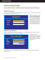
Main Screen Picture Adjust
Use the Up and Down buttons to highlight the “Picture Adjust” option. Press the “Menu”
button to access the submenu.
NOTE: Brightness of the main screen can also be
adjusted without entering the Main Menu
using the up and down display buttons.
14
Doc# 27-0027UM Rev 1.0 Issued 10/04
Use the Up and Down Keys
to highlight the desired option. Use the Left and Right
buttons to increase and decrease the Brightness and
Contrast characteristics of
the screen. Press “Exit” to
return to the Main Menu.
The new adjustments will
be applied automatically.
OPERATIONS
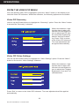
Main Screen Graphics Mode
Use the Up and Down buttons to highlight the “Graphics Mode” option. Press the “Menu”
button to access the “Graphics Mode” submenu.
“Graphics Mode” is used
to adjust the positioning of
the image. Use the Up and
Down Keys to highlight the
desired option. Use the Left
and Right buttons to adjust
the following modes: Horz
Coarse, Horz Fine, H Pos,
and V Pos.
The “Horz Coarse” option
adjusts the horizontal width
of the image.
The “Horz Fine” option adjusts the phase of the video
sampling clock.
Press “Exit” to return to
the Main Menu. The new
adjustments will be applied
automatically.
Main Screen Color Balance
Use the Up and Down buttons to highlight the “Color Balance” option. Press the “Menu” button to access the “Color
Balance” submenu.
Use the Up and Down Keys
to highlight the desired option. Use the Left and Right
buttons to adjust the colors
of the screen image.
Red
Green
Blue
Press “Exit” to return to the Main Menu. The new adjustments will be applied automatically.
15
Doc# 27-0027UM Rev 1.0 Issued 10/04
OPERATIONS
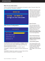
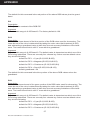
Main Screen Information
Use the Up and Down buttons to highlight the “Information” option. Press the “Menu” button to access the “Information” submenu.
Within this submenu, view
the video mode resolution,
the refresh rate, and the
sync mode. Press “Exit” to
return to the Main Menu.
The Firmware Version and
Build Date are also available on this screen.
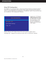
Menu Timeout:
Main Screen Configuration
#/.&)'52!4)/.
-ENU 4IMEOUT
The menu timeout is the
amount of time the menu
will appear while not in use
before it times out. When
the menu times out, it
disappears from the main
screen. Select with Up and
Down keys and adjust with
the Left and Right keys.
2ESET $EFAULT 3ETTINGS
Reset Default Settings:
#HANNEL 3ELECT !UTO
Resets all Main Menu settings to the factory default
settings. Select and press
the Menu button.
+6- #ONTROL /.
Channel Select Auto:
The StarGate has two channel options. Highlight “Channel
Select” and use the Left and Right keys to change channels. If both channels have been configured for use, the
following options are relevant:
AUTO: Automatically selects the available channel.
CHANNEL A: Allows the operator to choose Channel A as
active.
CHANNEL B: Allows the operator to choose Channel B as
active (channel B is optional--not standard).
16
Doc# 27-0027UM Rev 1.0 Issued 10/04
The Channel LEDs on the
front panel display buttons
reveal the active channels,
as well. See the section
regarding “Controls” for
more details on the channel
LEDs.
OPERATIONS
KVM Control (see KVM on screen on previous page):
Toggles ON/OFF to apply or remove preset KVM command features. The preset commands are programmed
as alternate functions of the firmware buttons on the front
of the panel. For predefining the KVM character strains,
please refer to SoftMenu instructions regarding KVM
Control.
RGB/Video PIP Control Screens
NOTE: When the KVM
Control is
turned ON,
the Main
Menu requires
the button be
held down for
extended length
of time to be
made active.
The unit will detect
as many PIPs as are
available. If no PIPs are
installed on the system,
the sub-menu will not be
displayed.
Highlight “PIP Select 1”.
The RGB and Video PIP
menus offer similar adjustment options. The following
sections describe the various RGB and Video menu
options.
NOTE: Before adjusting the Geometry, Color Balance,
or Image Quality of a PIP screen, the desired
PIP needs to be enabled. See the section titled,
“To Enable PIPs” for the proper initialization
procedure.
17
Doc# 27-0027UM Rev 1.0 Issued 10/04
OPERATIONS
FROM THE RGB PIP MENU
Once the desired RGB PIP is highlighted, press the “Menu” button on the display to access the RGB PIP submenu. Within the submenu, the following options are accessible:
RGB PIP Geometry
Use the Up and Down buttons to highlight the “Geometry” option. Press the “Menu” button
to access the “Geometry” submenu.
Within this submenu, highlight the item to alter, and
use the Left and Right buttons to adjust the PIP size,
the Horizontal Positioning
and the Vertical Positioning. Press “Exit” to return
to the RGB PIP submenu.
The new adjustments will
be applied automatically.
RGB PIP Color Balance
Use the Up and Down buttons to highlight the “Color Balance” option. Press the “Menu”
button to access the “Color Balance” submenu.
Within this submenu,
highlight the color to adjust,
and use the Left and Right
buttons to alter the Red,
Green and Blue color characteristics.
Press “Exit” to return to the RGB PIP submenu. The new adjustments will be applied
automatically.
18
Doc# 27-0027UM Rev 1.0 Issued 10/04
OPERATIONS
RGB PIP Image Quality
Use the Up and Down buttons to highlight the “Image Quality” option. Press the “Menu”
button to access the “Image Quality” submenu.
Within this submenu, highlight the item to adjust, and
use the Left and Right buttons to alter the PIP Contrast, the Horz Coarse and
the Horz Fine characteristics. Press “Exit” to return
to the RGB PIP submenu.
The new adjustments will
be applied automatically.
RGB PIP Configuration
PIP ENABLE: From the Main Menu, use the Up and Down buttons to locate the desired
PIP. Once highlighted, press the Menu button again to access the PIP submenu. Use the
Up and Down buttons to highlight the “Configuration” option. Press the Menu button to
enable the “PIP Configuration” submenu.
0)0 #/.&)'52!4)/.
0)0 %NABLE /&&
!UTO !DJUSTMENT
2ESET $EFAULT 3ETTINGS
#HANNEL 3ELECT !UTO
Highlight the “PIP Enable”
option and press the Left
or Right buttons to choose
the “ON” option. The PIP
screen will appear. Exit
the “PIP Configuration”
submenu by pressing the
“Exit” button.
RESET DEFAULT SETTINGS: Resets PIP values
to factory default values.
#+EY /&&
CHANNEL SELECT: Determines the active RGB PIP channel (A, B and Auto). If only one
channel is available, channel B will present no image.
AUTO ADJUSTMENT: Automatically adjusts the RGB PIP image to fit the screen. Undo
the adjustment by choosing the Reset Default Settings option.
CHROMA KEY: Toggles PIP chroma key function OFF or to DEFAULT Settings.
19
Doc# 27-0027UM Rev 1.0 Issued 10/04
OPERATIONS
FROM THE VIDEO PIP MENU
Once the desired Video PIP is highlighted, press the “Menu” button on the display to access the Video PIP submenu. Within the submenu, the following options are accessible:
Video PIP Geometry
Use the Up and Down buttons to highlight the “Geometry” option. Press the “Menu” button
to access the “Geometry” submenu.
50
EN
50
Within this submenu, highlight the item to alter, and
use the Left and Right buttons to adjust the PIP size,
the Horizontal Positioning
and the Vertical Positioning. Press “Exit” to return
to the Video PIP submenu.
The new adjustments will
be applied automatically.
50
Video PIP Video Settings
Use the Up and Down buttons to highlight the “Video Settings” option. Press the “Menu”
button to access the “Video Settings” submenu.
Within this submenu, highlight the item to alter, and
use the Left and Right buttons to adjust the Contrast,
Brightness, Color and Tint
characteristics.
Press “Exit” to return to the Video PIP submenu. The new adjustments will be applied
automatically.
20
Doc# 27-0027UM Rev 1.0 Issued 10/04
OPERATIONS
Video PIP Configuration
PIP ENABLE: From the Main Menu, use the Up and Down buttons to locate the desired
Video PIP. Once highlighted, press the Menu button again to access the PIP submenu.
Use the Up and Down buttons to highlight the “Configuration” option. Press the Menu button to enable the “PIP Configuration” submenu.
Highlight the “PIP Enable”
option and press the Left
or Right buttons to choose
the “ON” option. The PIP
screen will appear. Exit
the “PIP Configuration”
submenu by pressing the
“Exit” button.
0)0 #/.&)'52!4)/.
0)0 %NABLE /&&
2ESET $EFAULT 3ETTINGS
#+EY /&&
RESET DEFAULT SETTINGS: Resets PIP values to factory default values.
CHROMA KEY: Toggles PIP chroma key function OFF or to DEFAULT Settings.
21
Doc# 27-0027UM Rev 1.0 Issued 10/04
OPERATIONS
SOFTMENUS™
SoftMenus™ are control panel dialog screens accessed from the host computer, allowing
flexibility where positioning and environmental demands are a concern.
In order to access the SoftMenu™ features, the host serial port must be accessed at the
rear of the StarGate. The StarGate must be connected to the computer and software must
be installed.
The following initializing screen will appear as the SoftMenu™ software is launched:
Clicking on the “Exit” button will cancel the SoftMenu™ program from opening.
22
Doc# 27-0027UM Rev 1.0 Issued 10/04
OPERATIONS
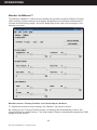
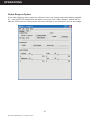
Monitor SoftMenus™
The Monitor SoftMenu™ dialog screen allows the operator to adjust Channel Configuration activity, Default settings, Auto Adjust, Brightness and Contrast characteristics,
Coarse and Positioning range, and Color Balancing of the main screen image in one
easy-to-use menu.
Monitor Screen “Factory Default” and “Auto Adjust” Buttons
To adjust the monitor screen settings, the “Monitor” tab must be active.
By clicking on the “Factory Default” button, all settings will automatically reset to the
prescribed factory default values. The “Auto Adjust” feature automatically adjusts the RGB
image to fit the screen.
23
Doc# 27-0027UM Rev 1.0 Issued 10/04
OPERATIONS
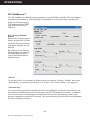
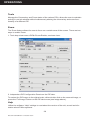
PIP SoftMenus™
The PIP SoftMenu™ tabs allow the operator to choose RGB and NTSC PIP Color Balancing and Image Quality or Video Settings configurations, as well as Factory Default settings and Chroma keying.
The settings for the RGB
and NTSC PIPs will be
different.
PIP “Factory Default”
Button
Before any changes can be
made, choose the PIP tab.
Once the PIP tab screen is
activated, settings can be
altered.
By clicking on the Factory
Default button, all settings
will automatically reset
to the prescribed factory
default values.
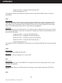
“Zoom”
To use the Zoom, the chroma key feature must be enabled. Click the “Enable” box under
“Chroma Key” to use the Zoom feature. For more on the “Zoom” feature, see page 27.
“Chroma Key”
The chroma keying function will alter the PIP color attributes so that the main screen can
be viewed from beneath the PIP screen when the PIP GUI wrapper is hidden. In addition,
a PIP screen can be viewed from beneath other PIP screens by distilling certain color
pixels to represent pertinent PIP content. The chroma keying functions are only adjustable
from the SoftMenu screens.
24
Doc# 27-0027UM Rev 1.0 Issued 10/04
OPERATIONS
“Enable” and “Hide/
Show Wrapper”
Click the “Enable” box to
enable the chroma keying
function. The “Hide/Show
Wrapper” toggle key, when
enabled, allows the operator to wrap the GUI PIP
wrapper around the PIP
image or hide it.
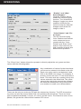
“Color Palette” and “Enter Color”
The PIP chroma keying
Color Palettes and manual
color values can be accessed with the “Color
Palette” and “Enter Color”
buttons. See below for details regarding manual and
default color operation.
The “Enter Color” button allows the operator to directly adjust the red, green and blue
values with the following table:
Any combination of values for the three base
colors can be entered in the fields to the left.
Each color value can be set between 0 and
255 on the RGB color range. For example, if
all three colors are set to “0” the result will be
black. This value acts as a center point to the
values entered in the offset field. The offset
value to the right is the amount the software
will offset the centerpoint color values from
one another to create color differentiation.
There can be only one color per PIP with the chroma key function. The PIP chroma keying color can also be chosen within PIP color palettes (shown below). There are three
types of palettes available: 8 colors, 27 colors, and 64 colors. The fewer the colors in the
palette, the greater the offset will be between PIP colors.
25
Doc# 27-0027UM Rev 1.0 Issued 10/04
OPERATIONS
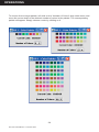
To choose from a larger palette, left click on the “Number of Colors” drop-down menu and
move the cursor down to the desired number of colors in the palette. The corresponding
palette will appear. Simply choose a color by clicking on it.
26
Doc# 27-0027UM Rev 1.0 Issued 10/04
OPERATIONS
Video Resync Option
If the Video Resync option has been chosen for the unit, please note the following capability . If the NTSC PIP image fails and does not recover, the “Video Resync” button will enable the PIP board to reanalyze the video input stream in an attempt to recover the image.
27
Doc# 27-0027UM Rev 1.0 Issued 10/04
OPERATIONS
MENU BAR
The SoftMenus’ menu bar also includes the “Edit” and “Tools” drop-down menus. Left
click on any of the following drop-down menus:
File
Load previously saved display settings and save settings in the “File” drop-down menu.
Multiple users may wish to alter the settings individually with this feature.
Edit
Manage, add, and remove the ports used by SoftMenus for communication with the “Edit”
drop-down menu.
28
Doc# 27-0027UM Rev 1.0 Issued 10/04
OPERATIONS
Tools
Manage the Chroma key and Zoom status of the various PIPs; allows the user to maintain
activity in one tab window while simultaneously altering the chroma key and zoom functionality of a different PIP.
Zoom
The Zoom feature allows the user to focus on a certain area of the screen. There are two
ways to enable Zoom:
1. Tools drop-down menu>PIP#>Zoom>Enable, as shown here:
2. Independent PIP Configuration Panels on the PIP tabs.
To restore the PIP image to its original scale, either double click on the zoomed image, or
press the “Full Image” button on the PIP tab screen (see image above).
Help
Utilize the software “Help” settings to read about the version of the unit, as well as information about Z Microsystems.
29
Doc# 27-0027UM Rev 1.0 Issued 10/04
OPERATIONS
NOTE : While Zoom is enabled in
SoftMenus, the Chroma key
function must remain enabled.
HOT KEYS
Hot Keys are only available on the Linux and Windows versions of Z Microsystems’ software. The following combinations of “hot” keys have been customized for ease of use of
the StarGate.
Ctrl + Tab
Press the “Control” and the “Tab” keys simultaneously to toggle between the Main Monitor
and PIP tabs, from left to right.
Ctrl + PIP # 1, 2, 3, etc.
Press “Control” and the number of the PIP (i.e. “1”) simultaneously to turn on a particular
PIP. Press the two keys again to turn the PIP off.
Ctrl + B
Press the “Control” and the “B” keys simultaneously to turn up the main image’s brightness in small increments.
30
Doc# 27-0027UM Rev 1.0 Issued 10/04
OPERATIONS
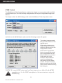
KVM Control
The SoftMenus KVM Control feature enables the display to communicate with the KVM
over the serial port. The ASCII string assignments can only be configured through SoftMenus.
To assign or alter the ASCII strings, click on the SoftMenus’ Tools drop-down menu.
Left click on the “KVM Setup” option and the following screen will appear:
The button images map to
the physical buttons on the
display panel.
Click on the buttons corresponding to the desired
string to gain access to the
assignment screens.
Click on the “Properties”
button to specify the serial
port configuration the display should use to communicate with the KVM.
Click the “OK” button to
save the settings and
exit from the KVM Setup
screen. Click the “Cancel”
button to exit from the KVM
Setup screen without saving
the changes.
NOTE: The exact ASCII strings and serial port properties are defined by the KVM
manufacturer. See the KVM manufacturer’s documentation to assign the
ASCII string.
31
Doc# 27-0027UM Rev 1.0 Issued 10/04
MAINTENANCE
MAINTAINING THE STARGATE
WARNING: Be sure to turn off the
power before you perform any
maintenance on the monitor.
WARNING: To avoid risk of electric
shock, do not disassemble the
monitor cabinet. Users cannot
service the monitor. User
maintenance is restricted to
cleaning as explained below.
CLEANING THE MONITOR
Unplug the monitor from the power outlet
before cleaning.
• To clean the flat panel display screen,
lightly dampen a soft, clean cloth with
water or mild detergent. If possible, use
a special screen cleaning tissue or solution suitable for the display.
• Isopropyl alcohol may also be used to
clean fingerprints or smudges on the
face of the monitor. First apply the alcohol to the soft lint-free cloth before wiping the monitor. Do not apply the alcohol
directly on the monitor.
32
Doc# 27-0027UM Rev 1.0 Issued 10/04
TROUBLESHOOTING
TROUBLESHOOTING THE STARGATE
No Main Display Image
If there is no image on the main screen, a signal will appear on the screen that states, “No
Input, Check Cable”. If the cable from the computer to the display is secure, determine the
color of the standby LED and follow the appropriate procedure below.
Black
Problem:
If the standby LED is black, there is no
power to the unit.
NOTE: These procedures only apply to
the main screen image, not
the picture-in-picture screens.
See next section for PIP screen
troubleshooting guide.
Recovery:
• Ensure the power cable is plugged
into the source.
• Connect the power cable to a
AC outlet. Ensure the AC outlet is
active.
• Wake up the display by pressing
the standby button.
Orange
Problem:
If the standby LED is orange, there is no
video signal.
Recovery:
• If Video A or Video B is selected,
ensure there is a video signal coming into the selected channel.
• Ensure there is a video signal
coming from the computer.
Green
Problem:
When the standby LED is green, there is
both power and a video signal. If there is
no image on the main display, there is a
possible hardware failure.
Recovery:
• Ensure the video signal coming
from the computer is not a black
screen.
• Contact Z Microsystems’ Customer Support Department.
33
Doc# 27-0027UM Rev 1.0 Issued 10/04
TROUBLESHOOTING
No Picture-in-Picture Option Appears on Main Menu
If no PIP menu is available from the Main Menu, the PIP has not been detected by the
controller. Recycle power to the unit by disconnecting power and then reconnecting
power. If no PIP is detected again when the Main Menu is powered up again, call Z Microsystems’ Customer Support Department for assistance.
No Picture-in-Picture Display Image
There are a few scenarios which may cause the image on the PIP to be black. To eliminate these concerns, follow the instructions below in the order they are presented:
1. Ensure the PIP is viewing something with contrast and shape and can be easily detected under normal viewing conditions.
2. If the PIP is viewing something with these qualities, and should be easily detected, the
values associated with Contrast and Color Balance may require adjustment. To ensure
the Contrast and Color Balance values are not the cause of the black screen, set the
values to the factory default settings. See section titled, “PIP SoftMenus™”.
3. In some StarGate configurations, there are two inputs (RGB and Video channels).
Ensure the correct channel is chosen for the desired PIP.
4. If the black screen is for the RGB PIP, perform an Auto Adjust in the PIP submenu.
5. If no PIP image appears, call Z Microsystems’ Customer Support Department for assistance.
34
Doc# 27-0027UM Rev 1.0 Issued 10/04
TROUBLESHOOTING
Display Image Has Vertical Bars
If the main image begins to display vertical bars, adjust the “Horz Coarse”. From the Main
Menu, use the Up and Down buttons to highlight the “Graphics Mode” option. Press the
“Menu” button to access the “Graphics Mode” submenu. Use the Left and Right buttons
to adjust the screen until the number of bars is reduced. Continue adjusting one step at a
time until the bars are no longer visible.
Display Image Appears Fuzzy
If the main image begins to appear fuzzy or “noisy”, adjust the “Horz Fine” until it is
reduced. The “Horz Fine” option adjusts the phase of the video sampling clock. To access
the “Horz Fine” submenu from the Main Menu, use the Up and Down buttons to highlight
the “Graphics Mode” option. Press the “Menu” button to access the “Graphics Mode”
submenu.
Power Light Does Not Illuminate
1. Check that power cable is properly connected to 110 VAC power supply.
2. Check that front panel power switch is on.
3. Check that power switch on back of StarGate display is on.
35
Doc# 27-0027UM Rev 1.0 Issued 10/04
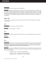
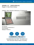
SCHEMATICS
.90
7.80
4.05
15.75
3.05
36
Doc# 27-0027UM Rev 1.0 Issued 10/04
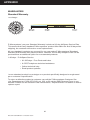
19.00
11.05
7.93
16.27
12.25
5.44
1.40
3.38
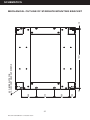
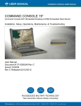
MECHANICAL OUTLINE FOR STARGATE
SCHEMATICS
37
Doc# 27-0027UM Rev 1.0 Issued 10/04
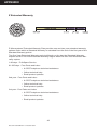
1.50
4.00
4.75
4.00
.10
8X C-BORE SLOTS FOR
10-32 SOCKET HEAD CAP SCREWS
18.21
.10
MECHANICAL OUTLINE OF STARGATE MOUNTING BRACKET
REPLACEMENTS
REPLACING PARTS
If the Z Microsystems Technical Support Engineer determines that the product needs to
be replaced, a Customer Service Representative will issue a Return Material Authorization (RMA) number.
An RMA number is required to return a product to Z Microsystems, regardless of the
reason for the return.
The Z Microsystems Customer Service Department/RMA Request Form will ask the customer to provide the following information:
• model number
• serial number
• problem
• return “ship to” address
• the name and address of the company department to which we will send
the invoice (if product is out of warranty or is different from the “ship to”
address.
• phone number and e-mail address of contact
• purchase order number
You will be given an RMA number and will be asked to send the product to:
Z Microsystems
ATTN.: (RMA#) It is very important to reference the RMA#
5945 Pacific Center Dr., Suite 505
San Diego, CA 92121
38
Doc# 27-0027UM Rev 1.0 Issued 10/04
APPENDIX
SPECIFICATIONS FOR STARGATE
The StarGate is designed to host a choice of LCD’s from several manufacturers based
upon customer requirements. The specifications unique to each particular LCD vary from
manufacturer to manufacturer. These particular specifications are available through our
sales department.
General Display Specifications
Display size
20.1 Inch
Pixels
1600 x 1200
Colors
16.7 Million
Control
Control Panel or SoftMenu
Options
One Picture-in-Picture Availalble
TouchScreen (SAW)
Power Consumption
110 W depending on whether the PIP option is
installed
AC Power Supply
100-240 VAC, 2.0 A, 50/60 Hz, 400 Hz
Power
Cables
Display RGB Cable Standard VGA 15-pin 10’
cable
Options: BNC and MIL-Circular (call factory to
discuss requirements)
RS232 Serial 6’ 9-pin DSUB provided (pins 2, 3, 5
straight through)
Power 6’ Cable, MIL-5015 Circular
Connector Standard (IEC Connector Optional)
Physical
Total Packaging Size
Total Weight
Environmental*
Operating Temp
15.75” H x 19.0” W x 5.44” D
Approximately 23 lbs. with no PIP
0° to 50° C
Extended Operating Temp** -20° to 50° C
Non-Op Temp
-40° to +70° C
Humidity
5%-95% Non-Condensing
Operating Altitude
Up to 15,000 ft.
Non-Op Altitude
Up to 40,000 ft.
Vibration
MIL-STD-167
Shock
MIL-STD-810E, 20 g’s, MIL-S-901D (in isolated
rack)
39
Doc# 27-0027UM Rev 1.0 Issued 10/04
APPENDIX
Fungus
Non-Nutrients/Contaminants
Reliability
MTBF
Display: 20,000 hrs w/ backlight change at 10,000
hrs.
MRRT
<30 minutes
Safety
UL 1950 (Used as a design guideline)
EMI
Options: MIL-STD-461E (call factory to discuss
requirements)
Quality/Workmanship
IPC/ISO 9001:2000 and applicable section of
MIL-HDBK-454
* Results of Environmental Tests pending
** Unit will power up and is legible at -20°C; backlight life is reduced
40
Doc# 27-0027UM Rev 1.0 Issued 10/04
APPENDIX
WARRANTIES
Standard Warranty
-no charge-
Z Microsystems’ one-year Standard Warranty includes a 90-day AirSpare Service Plan.
This means that if any standard Z Microsystems’ product fails within the first 90 days after
shipping, the customer will receive a new replacement.
All non-standard* products are covered for one year under Z Microsystems’ Standard
Warranty that includes free parts and labor. However, the 90-day AirSpare Plan can be
purchased as an additional option for non-standard products.
1-90 days - Z AirSpare Service
• 91-365 days - Free Parts and Labor
• 9-5 EST telephone technical assistance
• Online technical help
• Email product updates
*a non-standard product is a prototype or a product specifically designed or engineered
per a customer’s specification
To return a defective product a customer can call the Z Microsystems Customer Service Department at 1-858-657-1000, ext. 232, or fill out the RMA Request Form on our
website. Please see the section in this manual titled, “Replacements” for details on how to
replace a part.
41
Doc# 27-0027UM Rev 1.0 Issued 10/04
APPENDIX
Z Extended Warranty
Z Microsystems’ Extended Warranty Plan provides one and two year extended warranty
options under which a Standard Warranty is extended from the end of the first year of the
Standard Warranty period.
The One-Year Extended Warranty period will begin on the day the Standard Warranty
expires and the Two-Year Extended Warranty begins when the One-Year Extended Warranty expires.
1-90 days - Z AirSpare Service
91-365 days - Free Parts and Labor
• 9-5 EST telephone technical assistance
• Online technical help
• Email product updates
2nd year - Free Parts and Labor
• 9-5 EST telephone technical assistance
• Online technical help
• Email product updates
3rd year - Free Parts and Labor
• 9-5 EST telephone technical assistance
• Online technical help
• Email product updates
42
Doc# 27-0027UM Rev 1.0 Issued 10/04
APPENDIX
Z Preferred Warranty
Z Microsystems provides a Preferred Service Plan under which Z Microsystems will repair
or replace and return a defective product to the customer within one week of Z Microsystems’ receipt of the defective product.
1-90 days - Z AirSpare Service
91-365 days - Free Parts and Labor
• 9-5 EST telephone technical assistance
• Online technical help
• Email product updates
• Guaranteed One Week Turnaround
2nd year - Free Parts and Labor
• 9-5 EST telephone technical assistance
• Online technical help
• Email product updates
• Guaranteed One Week Turnaround
3rd year - Free Parts and Labor
• 9-5 EST telephone technical assistance
• Online technical help
• Email product updates
• Guaranteed One Week Turnaround
43
Doc# 27-0027UM Rev 1.0 Issued 10/04
APPENDIX
Z Airspare Warranty
365 DAYS
Z Microsystems provides an AirSpare Service Plan that will replace a defective product,
within the first year of the warranty period, with a new product the following business day.*
The AirSpare Service Plan does not cover special order items. A product may be deemed
a special order item at the discretion of the Customer Service Department. Z Microsystems, at its discretion, may offer the AirSpare Service Plan to a customer who purchases
a special order item at the one-year rate.
*Z Microsystems cannot guarantee next day delivery if contacted after 2:00 PM Pacific
Time. Calls on Fridays or before holidays will receive a new product the following business day.
1st Year - 24 hour replacement
• 9-5 EST telephone technical assistance
• Online technical help
• Email product updates
2nd Year - 24 hour replacement
• 9-5 EST telephone technical assistance
• Online technical help
• email product updates
44
Doc# 27-0027UM Rev 1.0 Issued 10/04
APPENDIX
Z On-Site Service
Z Microsystems also provides on site service and consultation to customers who require Z
Microsystems’ technical expertise.
45
Doc# 27-0027UM Rev 1.0 Issued 10/04
APPENDIX
Disclaimer
Z Microsystems warrants that every product is free from defects in materials, workmanship and conforms to Z Microsystems’ stringent specifications.
Z Microsystems calculates the expiration of the warranty period from the date the product
is shipped. This means that the ship date on your invoice is your product ship date unless
Z Microsystems informs you otherwise. During the warranty period, Z Microsystems will
provide warranty service under the type of warranty purchased for the product.
Replacement parts will assume the remaining warranty of the parts they replace. If a
product does not function as warranted during the warranty period, Z Microsystems will
repair or replace the part (with a product that is as a minimum functionally equivalent)
without charge.
If the product is transferred to another user, the warranty service is available to that user
for the remainder of the warranty period.
Z Microsystems’ warranties are voided if the covered product is damaged due to an accident or abuse. The warranty is voided if the product is shipped in sufficient packaging.
Under no circumstances is Z Microsystems liable for any of the following:
1. Third-party claims against you for losses or damages,
2. Loss of, or damage to, your records or data, or
3. Economic consequential damages (including lost profits or savings) or
incidental damages, even if Z Microsystems is informed of their possibility.
Some jurisdictions do not allow the exclusion or limitation of incidental or consequential
damages, so the above limitation or exclusion may not apply to you. This warranty gives
you specific legal rights and you may also have other rights that vary from jurisdiction to
jurisdiction.
Warranty does not take effect until full payment is received by Z Microsystems.
46
Doc# 27-0027UM Rev 1.0 Issued 10/04
APPENDIX
CUSTOMER SUPPORT
NOTE: For image problems, run
AUTO SETUP again before
consulting this section. In most
cases, AUTO SETUP can fix
the problems. See the Auto
Setup section for details.
NOTE: If possible, stay by the computer.
The Z Microsystems Technical
Support Representative may
wish to go through the problem
over the telephone.
If you are unable to correct the problem
yourself, contact:
Z Microsystems at:
(858) 657-1000
Fax: (858) 657-1001
Website: www.zmicro.com
Before calling, please have available as
much of the following information as possible:
1. Model and serial number from the
label on the monitor.
NOTE: More help, late-breaking
news and details of the
latest accessories for these
products may be found on the
worldwide web at: http://
www.zmicro.com
2. Purchase P.O.
3. Description of problem
4. Computer type and model
5. System configuration (hardware fitted, etc.)
6. System BIOS version number
7. Operating System and version
number
8. Display driver version number
9. Video Adapter Type
47
Doc# 27-0027UM Rev 1.0 Issued 10/04
APPENDIX
CUSTOMER FEEDBACK
We value feedback on our products, their performance, problems found, and welcome all
constructive suggestions. Please send such productive information in writing to:
Customer Service
Z Microsystems
5945 Pacific Center Blvd., Suite 505
San Diego, CA 92121
or www.zmicro.com
48
Doc# 27-0027UM Rev 1.0 Issued 10/04
APPENDIX
STARGATE SERIAL CONTROL ICD
The following serial port property settings must be in place in order for the host to have
communication with the display.
SPEED
19,200 BPS
DATA BITS
8
PARITY
None
STOP BITS
1
The serial control ICD commands are presented here for the user’s knowledge. The
commands are written and controlled by Z Microsystems and are not intended for the
customer to use. Any improper use of the commands may place the panel in an unstable
state and may degrade the image quality, thereby voiding the warranty by the user.
Command Structure
The command structure for the majority of the commands for the display follow the following structure:
Z<space>U<PIP#><space><command><space><argument>
where...
“PIP#” = the picture-in-picture (PIP) card on which the command
should act. The main image is PIP number “0”
“command” = the ascii string that represents the command
“argument” = the optional argument to the command
“space” = ascii character 0x32
The command structure must be succeeded by a carriage return (0x13).
The controller returns a string of tildes (‘~’) indicating that the command has been accepted and processed. Some of the commands return other information which will be
specified on a per command basis.
Unless otherwise specified the command strings examined in this document must be
placed in the above structure when being sent to the controller.
The commands will be broken down by the image on which it operates, either the main,
RGB, or NTSC image. There may be overlap between the different images and the commands that work on them.
Main Image—Standard Command Structure
The following commands operate on PIP number “0” otherwise known as the main image.
PAA
Description
PAA has the controller perform its auto adjust algorithm. This often helps the main image
49
Doc# 27-0027UM Rev 1.0 Issued 10/04
APPENDIX
properly position itself if an uncommon image stream is provided to the display.
Argument
No arguments.
PBB
Description
PBB adjusts the blue balance of the main images RGB setting.
Argument
The allowable range is 0-255 base10. The factory default is 128.
PBG
Description
PBG adjusts the green balance of the main images RGB setting.
Argument
The allowable range is 0-255 base10. The factory default is 128.
PBR
Description
PBR adjusts the red balance of the main images RGB setting. On certain displays, a low
brightness setting can cause the backlight to fade to black before reaching “0”.
Argument
The allowable range is 0-255 base10. The factory default is 128.
PCH
Description
PCH selects the channel that the controller should check for input. There are two channels through which that input can be provided—channels A and B. The unit can also be
placed in auto detect mode. The unit does not allow itself to be placed on a dead channel
after it has acquired a signal. If the controller has a good signal coming in on channel A
and the controller is told to listen to channel B and channel B has no signal the controller
will switch back to channel A.
Argument
For Auto mode 66, channel A 88, channel B 99 all base10. Default is Auto mode.
Return
The channel being listened to is returned in the following syntax:
=<mode>~~~
where “mode” = {66,88,99}
50
Doc# 27-0027UM Rev 1.0 Issued 10/04
APPENDIX
PDS
Description
PDS has the display place all of the settings back to the factory defaults.
Argument
No arguments.
PHC
Description
PHC adjusts the horizontal coarse setting.
Argument
The allowable range is 0-255 base10. The factory default is 128.
PHF
Description
PHF adjusts the horizontal fine setting.
Argument
The allowable range is 0-248 base10. The factory default is 119.
PHP
Description
PHP adjusts the horizontal position of the image.
Argument
The allowable range is 76-180 base10. The factory default is 128.
PIC
Description
PIC adjusts the images constrast.
Argument
The allowable range is 0-255 base10. The factory default is 128.
PUA
Description
If the display has been asked to auto adjust with the PAA command the PUA restores the
display’s image prior to the auto adjustment.
Argument
No arguments.
51
Doc# 27-0027UM Rev 1.0 Issued 10/04
APPENDIX
PVP
Description
PVP adjusts the vertical position of the image.
Argument
The allowable range is 106-150 base10. The factory default is 128.
Non-Standard Command Structure
The following commands do NOT use the standard command structure. They are sent “as
is” to the controller, succeeded by a carriage return (CR).
EPROM SAVE
Description
EPROM SAVE instructs the controller to store the display settings. The stored settings will
be used by the display when power is cycled until new settings are stored. This command
must be issued if any changes to the settings are made and the changes need to be maintained between power cycles.
Argument
No arguments.
FRST NTSC
Description
FRST NTSC is used to query the controller for the number of the first NTSC PIP card in
the display’s configuration. If there isn’t an NTSC PIP present in the configuration then
“0” is returned. NTSC PIPs follow RGB PIPs so if there are any RGB PIPs present in the
display’s configuration then the first NTSC number is equal to the last RGB number plus
one.
Argument
No arguments.
Return
The number of the first NTSC PIP card. The syntax for the returned value is the following:
=<value>~~~~
where “value” = the number of the first NTSC PIP.
FRST RGB
Description
FRST RGB is used to query the controller for the number of the first RGB PIP card in the
display’s configuration. If there is not an RGB PIP present in the configuration then “0” is
returned. RGB PIPs are always numbered first in the current display implementation.
Argument
52
Doc# 27-0027UM Rev 1.0 Issued 10/04
APPENDIX
No arguments.
Return
The number of the first RGB PIP card. There are two valid values that this command can
return “0” or “1”. If there is an RGB PIP provided with the display this command is issued
to then “1” will be returned otherwise “0” is returned indicating that there is not an RGB
PIP present. The syntax for the returned value is the following:
=<value>~~~~
where “value” = the number of the first RGB PIP.
LAST NTSC
Description
LAST NTSC is used to query the controller for the number of the last NTSC PIP card in
the display’s configuration. If the FRST NTSC command returned “0”, indicating that no
NTSC PIPs are present, then this command will return “0”.
Argument
No arguments.
Return
The number of the last NTSC PIP card. Valid return values for this command are 0 to
the maximum number of PIPs the display’s configuration can accept. The syntax for the
returned value is the following:
=<value>~~~~
where “value” = the number of the last NTSC PIP.
LAST RGB
Description
LAST RGB is used to query the controller for the number of the last RGB PIP card in the
display’s configuration. If there is not an RGB PIP present in the configuration (the FRST
RGB command returned “0”) then “0” is returned.
Argument
No arguments.
Return
The number of the last RGB PIP card. Valid return values for this command are “0” to
the maximum number of PIPs the display’s configuration can accept. The syntax for the
returned value is the following:
=<value>~~~~
where “value” = the number of the last RGB PIP.
The range of values returned by the FRST, LAST commands represent the values that are
to be used to indicate the PIP number in the command structure. If for example the FRST
RGB command returns a “1” and the LAST RGB command returns a “3” then there are 3
RGB PIPs on which commands can act. Therefore there are four valid values that can be
53
Doc# 27-0027UM Rev 1.0 Issued 10/04
APPENDIX
provide for PIP# in the command structure namely “0”, “1”, “2”, and “3”, where “0” acts on
the main image and “1”, “2”, and “3” act on the RGB PIP specified.
RGB PIP
The following commands are those that act on the RGB PIPs contained in the display’s
configuration.
PBB
Description
PBB adjusts the blue balance of the picture-in-picture’s RGB setting.
Argument
The allowable range is 0-255 base10. The factory default is 128.
PBG
Description
PBG adjusts the green balance of the picture-in-picture’s RGB setting.
Argument
The allowable range is 0-255 base10. The factory default is 128.
PBR
Description
PBR adjusts the red balance of the picture-in-picture’s RGB setting.
Argument
The allowable range is 0-255 base10. The factory default is 128.
PCK
Description
PCK toggles the chroma key feature ON/OFF.
Argument
Provide a “1” for ON and a “0” for OFF.
PDS
Description
PDS has the display place all of the RGB picture-in-picture settings back to the factory
defaults.
54
Doc# 27-0027UM Rev 1.0 Issued 10/04
APPENDIX
Argument
No arguments.
PHB
Description
PHB sets the upper-bound of the blue portion of the RGB value used for chroma key. The
upper-bound of the color is determined by taking the color value that is desired (0-255)
and adding a guardband value to take into account accuracy limitations of the hardware.
The upper-bound limit is still 255 even with the guardband.
Argument
The allowable range is 0-255 base10. The default value is dependent on which one of the
PIPs being addressed. There are currently four chroma key colors used as default colors
they are the following:
default for PIP 1 = Cyan (R:0,G:255,B:255)
default for PIP 2 = Magenta (R:255,G:0,B:255)
default for PIP 3 = Chartreuse (R:135,G:255,B:0)
default for PIP 4 = Sand (R:255,G:204,B:153)
default guardband = 50
The default for this command is the blue portion of the above RGB values plus the guardband.
PHC
Description
PHC adjusts the horizontal coarse setting.
Argument
The allowable range is 0-255 base10. The factory default is 128.
PHF
Description
PHF adjusts the horizontal fine setting.
Argument
The allowable range is 0-248 base10. The factory default is 119.
PHG
Description
PHG sets the upper-bound of the green portion of the RGB value used for chroma key.
The upper-bound of the color is determined by taking the color value that is desired
(0-255) and adding a guardband value to take into account accuracy limitations of the
hardware. The upper-bound limit is still 255 even with the guardband.
55
Doc# 27-0027UM Rev 1.0 Issued 10/04
APPENDIX
Argument
The allowable range is 0-255 base10. The default value is dependent on which one of the
PIPs being addressed. There are currently four chroma key colors used as default colors
they are the following:
default for PIP 1 = Cyan (R:0,G:255,B:255)
default for PIP 2 = Magenta (R:255,G:0,B:255)
default for PIP 3 = Chartreuse (R:135,G:255,B:0)
default for PIP 4 = Sand (R:255,G:204,B:153)
default guardband = 50
The default for this command is the green portion of the above RGB values plus the
guardband.
PHP
Description
PHP adjusts the horizontal location of the RGB PIP.
Argument
The allowable range is 0-800 base10. The position of the PIP is based on a relative location system. Every two display pixels is equal to 1 relative location increment. The origin
(0,0) is the upper-left hand corner of the display, with 800,0 being the upper-right, 0,600 is
the lower-left, and 800,600 being the lower-right. Taking into account the 2:1 ratio, a value
of 400 will place the RGB PIP’s upper-left hand corner at the half way point horizontal on
the display.
PHR
Description
PHR sets the upper-bound of the red portion of the RGB value used for chroma key. The
upper-bound of the color is determined by taking the color value that is desired (0-255)
and adding a guardband value to take into account accuracy limitations of the hardware.
The upper-bound limit is still 255 even with the guardband.
Argument
The allowable range is 0-255 base10. The default value is dependent on which one of the
PIPs being addressed. There are currently four chroma key colors used as default colors
they are the following:
default for PIP 1 = Cyan (R:0,G:255,B:255)
default for PIP 2 = Magenta (R:255,G:0,B:255)
default for PIP 3 = Chartreuse (R:135,G:255,B:0)
default for PIP 4 = Sand (R:255,G:204,B:153)
default guardband = 50
56
Doc# 27-0027UM Rev 1.0 Issued 10/04
APPENDIX
The default for this command is the red portion of the above RGB values plus the guardband.
PIC
Description
PIC adjusts the contrast of the RGB PIP.
Argument
The allowable range is 0-255 base10. The factory default is 128.
PLB
Description
PLB sets the lower-bound of the blue portion of the RGB value used for chroma key. The
lower-bound of the color is determined by taking the color value that is desired (0-255)
and subtracting a guardband value to take into account accuracy limitations of the hardware. The lower-bound limit is still “0” even with the guardband.
Argument
The allowable range is 0-255 base10. The default value is dependent on which one of the
PIPs being addressed. There are currently four chroma key colors used as default colors
they are the following:
default for PIP 1 = Cyan (R:0,G:255,B:255)
default for PIP 2 = Magenta (R:255,G:0,B:255)
default for PIP 3 = Chartreuse (R:135,G:255,B:0)
default for PIP 4 = Sand (R:255,G:204,B:153)
default guardband = 50
The default for this command is the blue portion of the above RGB values minus the
guardband.
PLG
Description
PLG sets the lower-bound of the green portion of the RGB value used for chroma key. The
lower-bound of the color is determined by taking the color value that is desired (0-255)
and subtracting a guardband value to take into account accuracy limitations of the hardware. The lower-bound limit is still “0” even with the guardband.
Argument
The allowable range is 0-255 base10. The default value is dependent on which one of the
PIPs being addressed. There are currently four chroma key colors used as default colors
they are the following:
default for PIP 1 = Cyan (R:0,G:255,B:255)
default for PIP 2 = Magenta (R:255,G:0,B:255)
default for PIP 3 = Chartreuse (R:135,G:255,B:0)
57
Doc# 27-0027UM Rev 1.0 Issued 10/04
APPENDIX
default for PIP 4 = Sand (R:255,G:204,B:153)
default guardband = 50
The default for this command is the green portion of the above RGB values minus the
guardband.
PLR
Description
PLR sets the lower-bound of the red portion of the RGB value used for chroma key. The
lower-bound of the color is determined by taking the color value that is desired (0-255)
and subtracting a guardband value to take into account accuracy limitations of the hardware. The lower-bound limit is still “0” even with the guardband.
Argument
The allowable range is 0-255 base10. The default value is dependent on which one of the
PIPs being addressed. There are currently four chroma key colors used as default colors
they are the following:
default for PIP 1 = Cyan (R:0,G:255,B:255)
default for PIP 2 = Magenta (R:255,G:0,B:255)
default for PIP 3 = Chartreuse (R:135,G:255,B:0)
default for PIP 4 = Sand (R:255,G:204,B:153)
default guardband = 50
The default for this command is the red portion of the above RGB values minus the guardband.
PON
Description
PON toggles the RGB PIP ON/OFF.
Argument
Provide a “1” to turn ON and a “0” to turn OFF.
PPC
Description
PPC changes the size of the RGB PIP. The aspect ratio of the native glass (4:3) is maintained by the display.
Argument
The allowable range is 10-800 base10. Providing a value of 800 makes the PIP fill the
display.
PVP
58
Doc# 27-0027UM Rev 1.0 Issued 10/04
APPENDIX
Description
PVP adjusts the vertical position of the RGB PIP.
Argument
The allowable range is 0-600 base10. The position of the PIP is based on a relative location system. Every two display pixels is equal to “1” relative location increment. The origin
(0,0) is the upper-left hand corner of the display, with 800,0 being the upper-right, 0,600 is
the lower-left, and 800,600 being the lower-right. Taking into account the 2:1 ratio a value
of 300 will place the RGB PIP’s upper-left hand corner at the half way point vertically on
the display.
NTSC PIP
The following commands are those that act on the NTSC PIPs contained in the display
configuration.
PCK
Description
PCK toggles the chroma key feature ON/OFF.
Argument
Provide a “1” for ON and a “0” for OFF.
PDS
Description
PDS has the display place all of the NTSC picture-in-picture settings back to the factory
defaults.
Argument
No arguments.
PHB
Description
PHB sets the upper-bound of the blue portion of the RGB value used for chroma key. The
upper-bound of the color is determined by taking the color value that is desired (0-255)
and adding a guardband value to take into account accuracy limitations of the hardware.
The upper-bound limit is still 255 even with the guardband.
Argument
The allowable range is 0-255 base10. The default value is dependent on which one of the
PIPs being addressed. There are currently four chroma key colors used as default colors
they are the following:
default for PIP 1 = Cyan (R:0,G:255,B:255)
default for PIP 2 = Magenta (R:255,G:0,B:255)
default for PIP 3 = Chartreuse (R:135,G:255,B:0)
59
Doc# 27-0027UM Rev 1.0 Issued 10/04
APPENDIX
default for PIP 4 = Sand (R:255,G:204,B:153)
default guardband = 50
The default for this command is the blue portion of the above RGB values plus the guardband.
PHG
Description
PHG sets the upper-bound of the green portion of the RGB value used for chroma key.
The upper-bound of the color is determined by taking the color value that is desired
(0-255) and adding a guardband value to take into account accuracy limitations of the
hardware. The upper-bound limit is still 255 even with the guardband.
Argument
The allowable range is 0-255 base10. The default value is dependent on which one of the
PIPs being addressed. There are currently four chroma key colors used as default colors
they are the following:
default for PIP 1 = Cyan (R:0,G:255,B:255)
default for PIP 2 = Magenta (R:255,G:0,B:255)
default for PIP 3 = Chartreuse (R:135,G:255,B:0)
default for PIP 4 = Sand (R:255,G:204,B:153)
default guardband = 50
The default for this command is the green portion of the above RGB values plus the
guardband.
PHP
Description
PHP adjusts the horizontal location of the NTSC PIP.
Argument
The allowable range is 0-800 base10. The position of the PIP is based on a relative location system. Every two display pixels is equal to 1 relative location increment. The origin
(0,0) is the upper-left hand corner of the display, with 800,0 being the upper-right, 0,600 is
the lower-left, and 800,600 being the lower-right. Taking into account the 2:1 ratio, a value
of 400 will place the NTSC PIP’s upper-left hand corner at the half way point horizontal on
the display.
PHR
Description
PHR sets the upper-bound of the red portion of the RGB value used for chroma key. The
upper-bound of the color is determined by taking the color value that is desired (0-255)
and adding a guardband value to take into account accuracy limitations of the hardware.
The upper-bound limit is still 255 even with the guardband.
60
Doc# 27-0027UM Rev 1.0 Issued 10/04
APPENDIX
Argument
The allowable range is 0-255 base10. The default value is dependent on which one of the
PIPs being addressed. There are currently four chroma key colors used as default colors
they are the following:
default for PIP 1 = Cyan (R:0,G:255,B:255)
default for PIP 2 = Magenta (R:255,G:0,B:255)
default for PIP 3 = Chartreuse (R:135,G:255,B:0)
default for PIP 4 = Sand (R:255,G:204,B:153)
default guardband = 50
The default for this command is the red portion of the above RGB values plus the guardband.
PLB
Description
PLB sets the lower-bound of the blue portion of the RGB value used for chroma key. The
lower-bound of the color is determined by taking the color value that is desired (0-255)
and subtracting a guardband value to take into account accuracy limitations of the hardware. The lower-bound limit is still “0” even with the guardband.
Argument
The allowable range is 0-255 base10. The default value is dependent on which one of the
PIPs being addressed. There are currently four chroma key colors used as default colors
they are the following:
default for PIP 1 = Cyan (R:0,G:255,B:255)
default for PIP 2 = Magenta (R:255,G:0,B:255)
default for PIP 3 = Chartreuse (R:135,G:255,B:0)
default for PIP 4 = Sand (R:255,G:204,B:153)
default guardband = 50
The default for this command is the blue portion of the above RGB values minus the
guardband.
PLG
Description
PLG sets the lower-bound of the green portion of the RGB value used for chroma key. The
lower-bound of the color is determined by taking the color value that is desired (0-255)
and subtracting a guardband value to take into account accuracy limitations of the hardware. The lower-bound limit is still “0” even with the guardband.
Argument
The allowable range is 0-255 base10. The default value is dependent on which one of the
PIPs being addressed. There are currently four chroma key colors used as default colors
they are the following:
61
Doc# 27-0027UM Rev 1.0 Issued 10/04
APPENDIX
default for PIP 1 = Cyan (R:0,G:255,B:255)
default for PIP 2 = Magenta (R:255,G:0,B:255)
default for PIP 3 = Chartreuse (R:135,G:255,B:0)
default for PIP 4 = Sand (R:255,G:204,B:153)
default guardband = 50
The default for this command is the green portion of the above RGB values minus the
guardband.
PLR
Description
PLR sets the lower-bound of the red portion of the RGB value used for chroma key. The
lower-bound of the color is determined by taking the color value that is desired (0-255)
and subtracting a guardband value to take into account accuracy limitations of the hardware. The lower-bound limit is still “0” even with the guardband.
Argument
The allowable range is 0-255 base10. The default value is dependent on which one of the
PIPs being addressed. There are currently four chroma key colors used as default colors
they are the following:
default for PIP 1 = Cyan (R:0,G:255,B:255)
default for PIP 2 = Magenta (R:255,G:0,B:255)
default for PIP 3 = Chartreuse (R:135,G:255,B:0)
default for PIP 4 = Sand (R:255,G:204,B:153)
default guardband = 50
The default for this command is the red portion of the above RGB values minus the guardband.
PON
Description
PON toggles the NTSC PIP ON/OFF.
Argument
Provide a “1” to turn ON and a “0” to turn OFF.
PPC
Description
PPC changes the size of the NTSC PIP. The aspect ratio of the native glass (4:3) is maintained by the display.
Argument
The allowable range is 10-800 base10. Providing a value of 800 makes the PIP fill the
display.
62
Doc# 27-0027UM Rev 1.0 Issued 10/04
APPENDIX
PVB
Description
PVB adjusts the NTSC PIP image brightness.
Argument
The allowable range is 0-255 base10. The factory default is 128.
PVC
Description
PVC adjusts the NTSC PIP image contrast.
Argument
The allowable range is 0-255 base10. The factory default is 128.
PVP
Description
Adjusts the vertical position of the NTSC PIP.
Argument
The allowable range is 0-600 base10. The position of the PIP is based on a relative location system. Every two display pixels is equal to “1” relative location increment. The origin
(0,0) is the upper-left hand corner of the display, with 800,0 being the upper-right, 0,600 is
the lower-left, and 800,600 being the lower-right. Taking into account the 2:1 ratio, a value
of 300 will place the NTSC PIP’s upper-left hand corner at the half way point vertically on
the display.
PVT
Description
PVT adjusts the NTSC PIP image color.
Argument
The allowable range is 0-255 base10. The factory default is 128.
63
Doc# 27-0027UM Rev 1.0 Issued 10/04
Z Microsystems, Inc.
5945 Pacific Center Blvd., Suite 505
San Diego, CA 92121
Phone: (858) 657-1000
Fax: (858) 657-1001
Website: www.zmicro.com
Copyright 2004 Z Microsystems, Inc. All Rights Reserved