1
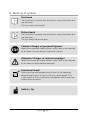
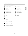
Comfort 220 Einbau- und Bedienungsanleitung GB Installation and Operating Instructions GB Operator System for Garages Anriebssystem für Garagen Anriebssystem für Garagen Anriebssystem für Garagen Anriebssystem für Garagen Einbau- und Bedienungsanleitung NL F Einbau- und Bedienungsanleitung I Einbau- und Bedienungsanleitung English Page 2 A. Contents Contents...............................................................................................3 Meaning of symbols ........................................................................4 - 5 Important safety advice ...................................................................6 - 7 Installation.....................................................................................8 - 16 01. Preparation .................................................................................................8 02. Required tools .............................................................................................8 03. Site requirements ........................................................................................8 04. Connect boom with operator unit...............................................................9 05. Mount suspension clamp to boom ..............................................................9 06. Mount lintel joining plate ..........................................................................10 07. Unlock carriage .........................................................................................10 08. Garage door operator with up-and-over door....................................10 - 11 09. Garage door operator with sectional door .........................................11 - 12 10. Garage door operator with retractable up-and-over door ..................12 - 13 11. Suspension of the operator system............................................................14 12. Installation of bulb ....................................................................................14 13. Quick release .....................................................................................15 - 16 E. Hand transmitter .........................................................................17 - 19 14. Hand transmitter - operation and accessories ............................................17 15. Hand transmitter - programming: ......................................................18 - 19 F. Control unit connections .............................................................20 - 21 16. Module aerial ............................................................................................20 17. Connection of external control elements...................................................21 G. Display functions and programming possibilities ..........................22 - 47 18. 19. 20. 21. 22. 23. 24. 25. 26. 27. 28. Meaning of symbols..................................................................................22 Summary on electronic control unit ..................................................22 - 23 Preparation of programming..............................................................23 - 24 Summary on display functions...................................................................25 Basic functions of the operator ..........................................................26 - 27 Programming of basic level ................................................................28 - 32 Extended operator functions..............................................................33 - 43 Short programming instructions.........................................................44 - 45 Insert cover ...............................................................................................46 Cabling plan .............................................................................................46 Wiring diagram Comfort 220 ............................................................46 - 47 H. Test instructions...........................................................................48 - 49 I. Error numbers .....................................................................................50 J. Initial operation and maintenance.......................................................51 K. Technical details ..................................................................................52 L. Index of illustrations............................................................................53 M. Manufacturer's declaration ..........................................................54 - 55 N. Declaration of conformity ............................................................56 - 57 O. Supply package .................................................................................. English Page 3 GB A. B. C. D. B. Meaning of symbols Text book The instructions comprise two documents, one picture book and one text book. This sign marks the text part. Picture book The instructions comprise two documents, one picture book and one text book. This sign marks the picture part. Caution! Danger of personal injuries! Here follow important safety advices, which have to be observed by all means to avoid danger of personal injuries! Attention! Danger of material damage! Here follow important safety advices, which have to be observed by all means to avoid material damages! Functional check: After mounting and programming of most of the operating elements the function of the control unit can be tested. This is very useful to find out any error immediately and to save time when looking for errors. Advice / tip English Page 4 B. Meaning of symbols Operation, voltage rpm sensor Impulse To control unit Malfunction Cable slack device End position OPEN Connection lead End position CLOSED Wicket door switch Power limit Automatic timer STOP Lighting External control elements Electronic aerial Photocell Transmitter (Optosensor, photocell) Receiver (Optosensor, photocell) Closing edge safety device English Page 5 GB Symbols of control unit, operator etc.: C. Important safety advice Installation and initial operation of this operator may only be carried out by qualified and trained specialist personnel. Qualified and trained specialist personnel in the sense of this description are persons who have been trained and are supervised sufficiently by electricians and therefore are able to recognize the special hazards arising from electricity. Moreover they need to have the following qualifications corresponding to the respective work to be done, especially: • Knowledge of the relevant electro-technical regulations, • Training in use and maintenance of necessary safety equipment. Caution! Before installation of the operator: • Remove all cables or chains that are not necessary. • Put all devices, which are not necessary after the installation of the operator, out of operation. • Test the mechanic situation of the door and check whether it is balanced and can be opened and closed correctly. Caution! Before starting cabling works please disconnect the operator by all means from power supply and keep a safety time of 10 sec. Only after this time period has expired, the operator is without voltage! • Observe local safety regulations! • Always lay mains and control cables separately! Control voltage 24 V DC. Caution! Before initial operations of the control unit please make sure that there are neither persons nor objects in the operation range of the door, as for some settings the door has to be moved! English Page 6 • All impulse and control devices (e.g. radio code keypad) that are fixed to the wall have to be mounted in view of the door, but in a safe distance to the movable parts of the door. The min. mounting height of 1,5 m has to be kept. • All existing emergency command devices have to be tested before initial operation. • The operator may only be mounted when the door is closed! • Before initial operation the operators of the door system or their representatives have to be made familiar with the use of the system. • The warning signs against trapping that are enclosed in the operator package have to be stuck permanently to a well visible place. • After the installation please make sure that no parts of the door project neither to public sidewalks nor streets. Caution! In case these warnings are ignored, personal injuries and material damages may occur Advice! To avoid installation errors and damages to the door and operator, please follow by all means the mounting steps of these installation instructions! Please keep these installation instructions for further reference, they contain important information regarding operational checks and maintenance works. English Page 7 GB C. Important safety advice D. Installation 1 Preparation • Unpack the boom and the motor unit and keep it ready for mounting. 2 Required tools Combination wrench SW 10 Combination wrench SW 13 Socket wrench SW 8 Socket wrench SW 10 Socket wrench SW 13 Screw driver, size 5 Screw driver, size 8 Phillips Screw driver, size 2 Masonry drill ø 6 mm Masonry drill ø 10 mm Metal drill ø 5 mm Pliers Hack saw Electric drill Electric drill Attention! Before drilling, cover the motor unit with foil or cardboard. Drilling dust and chippings can lead to malfunctions. 3 Site requirements • Please suspend the motor unit together with the boom in such a way, that the upper door edge lies approx. 10 mm below the downward horizontal boom edge- measured at the highest point of the opening course (see points 8, 9 and 10). • Mount the unit to the ceiling according to the site requirements. Please observe as well the indicated measurements for wall plug drilling. English Page 8 D. Installation Connect boom with the operator unit • Push the adapter sleeve (A) to the stop onto the fine toothed gear shaft (fig. D.3). If you turn the operator unit by 90°, the installation depth is lessened by 150 mm. For this the reference point switch (B) has to be turned as well to the foreseen position (fig. D.4). • Put the boom in its right position to the adapter sleeve. • Align the boom laterally. • Push the boom onto the operator unit using slight pressure (fig. D.5). Attention! Do not use force! If the boom is aligned parallel to the surface of the operator unit, a short pull on the carriage is sufficient to lower the boom onto the operator unit without force. • Screw the boom to the operator unit using two clamp brackets (C) and four hex screws SW 8 (D) (fig. D.6). 5 Mount suspension clamp to boom • Mount the suspension clamp to the boom (for function and position of the suspension clamp please look up point 3). English Page 9 GB 4 D. Installation 6 Mount the lintel joining plate • To protect the pull element, which is integrated in the boom (chain or toothed drive belt), against unauthorized and forced dismantling from the outside (break-in), push the red securing sleeve (D) over screw (E) (fig. D.8). • Then connect the lintel joining plate (A) and the boom end piece (B) with bolt (C) (fig. D.9). 7 Unlock the carriage • Push the red release pin (B) to the stop into the red opening of the carriage (fig. D.10). • Pull the cable (A) (fig. D.12). • The carriage is now unlocked and can be slid freely in the boom and connected to the door. • For further information regarding the carriage please look up point 13. 8 Garage door operator with up-and-over door • Screw the lintel joining plate (A) together with the boom to the top frame, lintel or ceiling, so that the upper edge of the door leaf lies approx. 10 mm below the downward edge of the horizontal boom - measured at the highest point of the opening course (see as well point 3). • Put the operator unit onto a trestle or another suitable object until it is fixed later to the ceiling. English Page 10 D. Installation • Screw this to the centre of the upper edge of the door leaf using 4 screws (drill ø 5 mm). • Insert the door link (D) together with the bolt (F) into the carriage (E). • Fix it with 2 screws. • Connect the door link and the door link bracket. Advice! Remove the door locks or put them out of function! 9 Garage door operator with sectional door • Screw the lintel joining plate (A) with boom to the lintel or ceiling, so that the upper lamella of the door lies approx. 10 mm below the horizontal downward boom edge - measured from the highest point of the opening course (see as well point 3). • Put the motor unit on a trestle or another suitable object until it is fixed later to the ceiling. • Join two door link brackets (B) to the door connector (C). • Screw this to the centre of the upper edge of the door leaf using 4 screws (drill ø 5 mm). If necessary, the motor unit can be installed 200 mm off-centre. • For wooden sectional doors please use wood-screws Ø 5 x 35 mm (drill ø 3 mm). • Turn two self-tapping screws (D) so far into the door connector, until the points of the screws are in front of the lamella. English Page 11 GB • Connect two door link brackets (B) to the door connector (C). D. Installation • Insert the door link (E) with bolt (G) into the carriage (F). • Fix it with 2 screws. • Connect door link and door link bracket. Advice! Remove the door locks or put them out of operation! Attention! In case the upper door lamella does not contain any stiffening plates or reinforcement straps (e.g. with one-wall doors): Use additionally door connector attachment Special 111, Art.-No. 47 574 (not part of the supply package, compare Fig. D 15). In the other case please only use the door connector elements, because there is enough stability due to the stiffening. 10 Garage door operator for retractable up-and-over door Required accessories: • Adapter arm Special 102, • Photocell Special 613, • Photocell Special 613, • 2-wire photocell, These are not part of the supply package Art.-No. 563 828 Art.-No. 153 550 Art.-No. 152 675 Art.-No. 47 816 Comfort 220. Advice! Remove the door locks or put them out of operation! English Page 12 • Screw the lintel joining plate (A) with boom to the top door frame, lintel or ceiling, so that the upper edge of the door leaf lies approx. 10 mm below the horizontal downward edge of boom - measured from the highest point of the opening course (see as well point 3) (fig. D.16). • Put the motor unit on a trestle or another suitable object until it is fixed later to the ceiling. Fitting the adapter arm: • Screw the support bracket (B) to the upper door edge using 6 self-tapping screws (Drill ø 5 mm) (fig. D.17). • Centre of support bracket equals to the centre of boom. • Put adapter arm (C) into support bracket (B) (fig. D.18). • Screw it to the door cross strut (E) using two angle plates (D) (fig. D.18). Drill ø 5 mm in the door cross strut (4x) Drill ø 7 mm in the adapter arm (2x) • Screw the angle plates to the adapter arm using two screws M6 x 10 and hexagon nuts. • Insert linking bar (G) with bolt (J) into the carriage (F) (fig. D.19). • Fix it with 2 screws. • Open door fully • Connect linking bar (G) with the adapter arm (C) (fig. D.19). • Observe the indicated measurements. While lowering the boom and by extending the linking bar the door opening is enlarged. The linking bar may only be extended so far that the inner pressure rolls (H) do not touch the fixing screws (I). English Page 13 GB D. Installation D. Installation 11 Suspension of the operator system Suspension of motor unit • Fix 1 support plate (A) above the motor unit (see as well point 3). • Bend the plate according to site requirements. Suspension of boom • Push 1 support plate (A) through suspension clamp (B) and bend projecting parts. • Positioning of the suspension of boom (see as well point 3). 12 Installation of the bulb Attention! Please disconnect by all means the unit from power supply before you change the bulb. • Turn in a bulb E14 (max. 40 W). • Clip in the lamp cover. • Turn in the securing screw. After given impulse the bulb is on for approx. 3 min. Advice! Bulbs are not covered by warranty. English Page 14 D. Installation Attention! Actuating the quick release may lead to uncontrolled movements of the door: - in case the door springs are weak or broken. - in case the door is not balanced. When disengaged, the door may only be moved in a moderate speed! When the door is opened by hand, the carriage may collide with the clamp strap of the suspension and with the motor unit. • Limit the door travel in open direction by means of construction works. • Install the pull cord of the quick release in min. 1,8 m height. • Attach the sign 'Instructions to use the pull cord of the quick release' to the pull cord. English Page 15 GB 13 Quick release D. Installation Operational check: After the operator has been mounted, the following tests have to be carried out: - In 'close' direction the door runs against an obstacle of 50 mm that lies on the floor: -> The door has to reverse. For operators for doors with openings in the door wing (diameter of the opening > 50 mm): - A load of 20 kg is put to the middle of the bottom door edge: -> The door stops as soon as the open command is given. Separate door from operator • Pull the cable (A) downward to the stop in order to separate the door from the operator (Fig. D.22). Connect door and operator again • Push the red release pin (B) back in the direction of the arrow (D.24). • Start the door operator. The symbols on the downward side of the carriage show the actual situation: The door is separated from the operator. ->The front edge of the movable slide element (C) is above the arrow of the symbol 'lock open' (fig. D.23). The door is connected to the operator or will be connected automatically after the next door travel. ->The front edge of the movable slide element (C) is above the arrow of the symbol 'lock closed' (fig. D.24). English Page 16 E. Hand transmitter A B C D E Battery - transmission control light Operating buttons Battery cover Battery 3V CR 2032 Coding plug • Please open the cover to change or insert the battery. Observe right poling when changing the battery (fig. E.2). Caution! - Only operate the hand transmitter after you have made sure that there are neither persons nor objects in the operating range of the door. - Children are not allowed to play with hand transmitters! Advice! Batteries are excluded from warranty. Fixing accessories for hand transmitter: Attachment clip, suitable to fix the hand transmitter to a visor in the car (fig. E.3). English Page 17 GB 14 Hand transmitter - Operation and accessories E. Hand transmitter 15 Hand transmitter - Programming: Learn coding (if necessary) This function is meant to transmit a code from an existing hand transmitter to an additional hand transmitter (fig. E.4). Advice! Both sides of the plug connections can be used in an identical way. Attention! When actuating the hand transmitter, the door may be started! Step 1: • Connect both transmitters via the enclosed coding plug. Step 2: • Actuate the existing transmitter and hold the button. The LED in the transmitter is glowing. Step 3: • Actuate the desired button on the new hand transmitter and still hold the button of the existing transmitter. After 1 - 2 sec. the LED on the new transmitter is on permanently. The programming is terminated. The new hand transmitter has now taken over the coding of the existing hand transmitter. • Take out the coding plug. English Page 18 E. Hand transmitter Advice! GB For multi-channel transmitters this procedure has to be carried out separately for every single button. Change coding It is possible to change the coding of the remote control, in case a hand transmitter has gone lost. For this insert the coding plug into the hand transmitter that has to be re-programmed (fig. E.5). Step 4: • Insert the coding plug into the hand transmitter • Short-circuit one of the outer pins of the coding plug with the centre lead (e.g. by means of a screwdriver). • Actuate the desired button on the hand transmitter. The integrated random program generates a new code. The LED is flashing quickly. As soon as the LED on the hand transmitter is on permanently, release the button of the hand transmitter and remove the coding plug. Advice! After a new coding of the hand transmitter the garage door operator has to be re-programmed to the new code, because the old code is lost irrevocably. Advice! For multi-channel transmitters this procedure has to be carried out separately for every single button. English Page 19 F. Control unit connections 16 Module aerial Protection category: only for dry buildings A B Module aerial Holder for aerial • Insert the module aerial into the holder on the operator unit. Advice: Due to the digital safety encryption the operating range may vary. If necessary, the module aerial can be installed outside the building in order to achieve a larger operating range. For this an extension kit, protection category IP 65, is required (not part of the supply package). English Page 20 F. Control unit connections A B C D E Connection lead X 10 for control elements (Marantec system cabling), Connection terminals for control elements on building 1 = GND 2 = Impulse 3 = + 24 V DC max. 50 mA 70 = GND 71 = 2-wire system photocell (Art.-No. 47 816) Control unit Short-circuit plug Socket X 20 (connection for longer module aerial IP 65) Attention! Do not connect the short-circuit plug (D) to the socket (E)! • Before a connection with system cabling please remove the short-circuit plug (D) (fig. F.2). (e.g.: interior button or key switch outside; not part of the Marantec supply package). Please connect control elements on site only to the specially designated connection terminals (B). (fig. F.3). English Page 21 GB 17 Connection of external control elements G. Display functions and programming possibilities 18 Meaning of symbols: LED off LED on LED flashing slowly LED flashing quickly 19 Summary on electronic control unit A B C D E F G H I Sign for external photocell Sign for end position open / door opened - is on, as soon as the end position 'door open' is reached Sign for end position close / door closed - is on, as soon as the end position 'door closed' is reached. Sign for malfunction - is flashing in case of malfunction Sign for power limit: - LED 2 and 6 are flashing: power limit OPEN -LED 2 and 4 are flashing: power limit CLOSE Sign for programming remote control - is on when button is actuated - is flashing on receipt of valid signal from hand transmitter Programming button A / Test button 'OPEN' Programming button B / Test button 'CLOSE' Programming button C (Programming mode, menu selection / save programming) Display for voltage - is on at voltage - goes out for one second if motor stops English Page 22 N O P Connection terminals for external impulse button, 2-wire system photocell (Art.-No. 47 816) Socket for 'external control elements' Socket for 'electronic aerial', 'system photocell' Error messages Advice: To determine the error number add the figures of the irregularly flashing LED’s. See as well point I 'error numbers'. In case of a malfunction the control light MALFUNCTION (D) is flashing. • Shortly press button 쒊 . The current error number is displayed by irregularly flashing LED's (e.g. error 7). 20 Preparation for programming - The operator has to be mounted ready for operation. - The door is not yet closed completely. - If there is a driveway photocell, it should be connected! Advice: If the photocell / photocells are correctly mounted and aligned, the function 'photocell' is recognized automatically during programming! English Page 23 GB G. Display functions and programming possibilities G. Display functions and programming possibilities • Remove the motor cover. • Stick the enclosed sticker 'short programming instructions' inside the cover. • Before programming the operator, insert a battery into your hand transmitter. Programming is carried out with the three buttons (쒊, 팬 or 팫). Advice: The programming is cancelled if none of the three buttons (쒊, 팬, 팫) is actuated during a time period of more than 120 sec. All functions saved before with button 쒊 remain unchanged. When programming is cancelled, LED 6 is flashing. After shortly pressing button 쒊 the error message 7 is displayed. Attention! The operator has two programming levels. For normal operation of the operator you only program the end positions and the remote control in the 1st programming level. Button 쒊 must not be pressed longer than 10 sec. because otherwise some important parameters set by factory will be changed. Changes in the 2nd programming level may only be carried out by specialists. English Page 24 G. Display functions and programming possibilities During normal operation the display shows following door situations: Display functions After having switched on the power supply the control unit carries out a self-test (for approx. 2 sec. all LED’s are on). Display of door situations: Door in end position OPEN Door in end position CLOSED Door passes the reference point Malfunction, current error message Remote control is actuated Button is actuated Operating voltage English Page 25 GB 21 Summary on display functions G. Display functions and programming possibilities 22 Basic functions of the operator Programming sequence: • Press button 쒊 for approx. 2 sec. and release it. The control unit changes from operating state to the programming state of the basic functions. LED 2 flashes and all others are on. Changes in programming menu are carried out by pressing the buttons 팬 or 팫. The current values are saved with button 쒊. The control unit changes to the next programming menu. If the button 쒊 is pressed and no changes via buttons 팬 or 팫 have been carried out, the respective programming menu is skipped and the settings remain unchanged. After the last programming menu the programming of the operator basic functions is terminated, recognizable by all LED’s going off in the sequence 8 - 1. English Page 26 G. Display functions and programming possibilities General advice regarding the programming of control unit If the control unit is in programming mode and none of the three programming buttons (팬, 팫,쒊) is pressed during a time period of 120 sec., the programming procedure is cancelled and the control unit changes to operating mode). Advice: The end positions can only be programmed if there is a valid reference point. For this travel the door electrically once to open or close position. Display of the reference point The operator passes the reference point sensor: • LED 5 shortly glows up. Set the positions Advice: The control unit works without press-and-hold! • Press button 팬 or 팫 to travel the door to the desired door position. English Page 27 GB Advice regarding programming: G. Display functions and programming possibilities 23 Programming of the basic level 1. Programming of 'end position OPEN' • Press button 쒊 for approx. 2 sec. and then release it. LED 2 is flashing and all others are on. • Press button 팬 to set the end position OPEN. Carry out the fine adjustment with button 팬 or 팫. Advice: The reference point has to be passed 1x! • Save the end positions with button 쒊. The control unit changes automatically to the programming of 'end position CLOSE'. English Page 28 G. Display functions and programming possibilities LED 4 is flashing and all others are on: • Press button 팫 to set the end position CLOSE. Carry out the fine adjustment with button 팬 or 팫. Advice: The reference point has to be passed 1x! • Save the end position with button 쒊. The control unit changes automatically to the programming of 'remote control'. English Page 29 GB 2. Programming of the 'end position CLOSE' G. Display functions and programming possibilities 3. Programming of remote control LED 7 is flashing and all others are on. • Actuate the respective button on the hand transmitter until LED 7 is flashing quickly. The control unit has now learned the code of the hand transmitter. • Press button 쒊 to save the code of the remote control. • Press again button 쒊 to terminate the programming. The control unit is now in operating mode (in case of power failure all settings remain unchanged). English Page 30 G. Display functions and programming possibilities All menus can be reset by a RESET function to the original values set by factory. For this carry out the steps described in the point 'Programming of the basic level'. After the remote control has been saved, the control unit changes to the programming menu 'RESET factory settings'. 4. Programming 'RESET factory settings' LED 8 is flashing and all others are on: • Press button 팬 or 팫 to go to function 'reset'. LED 1 is flashing quickly; function 'no reset' is selected. All programmed values remain unchanged. LED 1 is on; function 'reset' is selected. All programmed values are overwritten by the values set from factory. • Press button 쒊 to confirm reset function. When 'reset' has been selected, the control unit carries out a new start, recognizable by all LED's glowing for 2 sec. The control unit is now in operation mode (settings from factory), in case of power failure all settings remain unchanged. English Page 31 GB Advice: G. Display functions and programming possibilities Learning of drive power: Attention! If the operator cuts out during the test run and LED 8 and LED 2 are flashing quickly (error number 10 / automatic cut-out): • Set the automatic cut-out • For this look up point 2: Programming 2nd level, point 2 + 3. • Travel the operator (with door engaged) completely and without interruption two times from door position 'DOOR CLOSED' to door position 'DOOR OPENED' and vice versa. During these two learning travels the operator determines the maximum push and pull force which is required to move the door. After two further complete door travels the operator is definitely ready for operation. These settings remain unchanged even if power supply is interrupted, but they can, nevertheless, if necessary, be changed as described before. Test: • Press button 팬. –> The door must open and travel to the 'door open' position, that has been set by you. • Press button 팫. –> The door must close and travel to the 'door closed' position, that has been set by you. • Shortly press the button on your hand transmitter. -> The operator moves the door to 'OPEN' resp. 'CLOSE' direction. • Press the button on your hand transmitter again during the operator run. -> The operator must stop The next push onto the button causes the operator to run in the opposite direction. English Page 32 G. Display functions and programming possibilities Advice: The values for the automatic cut-out (= max. force) and learning power limit (= power curve) can be set manually in the 2nd programming level. A setting should always be carried out as soon as a less sensitive setting has to be chosen due to door travel properties caused by site conditions, as otherwise the automatic cut-out or power limit would react and cause malfunctions. In general you have to take care that the allowed operating forces according to EN 12445 and EN 12453 are not exceeded. English Page 33 GB 24 Extended operator functions (2nd programming level) G. Display functions and programming possibilities Advice: Changes in the programming levels of the extended operator functions may only be carried out by specialists! Explanation of the extended operator functions: Functions Explanation Settings from factory Menu 1: - programming external Setting whether the operator is photocell no photocell existing run with or without photocell. Menu 2: - power limit OPEN The sensitivity of power limit step 5 can be set in steps from 1 - 16. Menu 3: - power limit CLOSE The sensitivity of power limit step 5 can be set in steps from 1 - 16. Menu 4: - offset learned power limit The sensitivity of power limit step 13 can be set in steps from 2 - 16. Menu 5: - operator speed The speed the door is moved step 16 (max. speed) by the operator can be set English Page 34 G. Display functions and programming possibilities Advice: Still hold the programming button 쒊 when LED 2 starts to flash after 2 sec. In order to come to the 2nd programming level, hold programming button 쒊 for further 8 sec. (LED 2 is then flashing quickly). • Press button 쒊 for more than 10 sec, until LED 2 flashes quickly. • Release button 쒊. LED 1 flashes. • Press button 팬 to make a connection of external photocells possible. - LED 1 is on: Operation with system photocell - LED 1 is on, LED 2 is flashing: Operation with 2-wire photocell - LED's 1 and 2 are on: Operation with system and 2-wire photocell • When pressing button 팫 the operator can be run without external photocell: - LED 1 is flashing. • Save your setting with programming button 쒊. The control unit changes automatically to the programming procedure 'automatic cut-out OPEN'. English Page 35 GB 1. Programming of external photocell G. Display functions and programming possibilities 2. Programming 'automatic cut-out OPEN' Attention! The automatic cut-out is set automatically. Only change it if necessary (error No. 10) When increasing the set value the max. force in OPEN direction is increased and thus the sensitivity of the automatic cut-out is reduced. Attention! Always test the max. allowed operating forces according to EN 12445 and EN 12453! Advice: The setting of the automatic cut-out corresponds to the maximum power of the operator. At the first travel to OPEN or CLOSE direction after 'POWER ON' the automatic cut-out is effective according to the adjustment. For further travels the self-learned power, that is more sensitive, is effective. The automatic cut-out is still the upper limit of power. English Page 36 G. Display functions and programming possibilities • With button 팬 or 팫 the 'automatic cut-out' can be set in steps from 1 (most sensitive value) to 16 (according to table). • Save your setting with programming button 쒊. The control unit changes automatically to programming of 'automatic cut-out CLOSE'. Advice! When re-programming the end positions (1st programming level) the pull force is learned once more. With new setting of the end positions the force values are determined automatically. Depending on the door travel properties increasing of the force values may be necessary. English Page 37 GB LED's 2 and 6 are flashing. G. Display functions and programming possibilities 3. Programming 'automatic cut-out CLOSE' Attention! The automatic cut-out is set automatically. Only change it if necessary (error No. 10) When increasing the set value the max. force in CLOSE direction is increased and thus the sensitivity of the automatic cut-out is reduced. Attention! Always test the max. allowed operating forces according to EN 12445 and EN 12453! Advice: The setting of the automatic cut-out corresponds to the maximum power of the operator. At the first travel to OPEN or CLOSE direction after 'POWER ON' the automatic cut-out is effective according to the adjustment. For further travels the self-learned power, that is more sensitive, is effective. The automatic cut-out is still the upper limit of power. English Page 38 G. Display functions and programming possibilities • With button 팬 or 팫 the 'automatic cut-out' can be set in steps from 1 (most sensitive value) to 16 (according to table). • Save your setting with programming button 쒊. The control unit changes automatically to programming 'offset learned power limit'. Advice! When re-programming the end positions (1st programming level) the pull force is learned once more. With new setting of the end positions the force values are determined automatically. Depending on the door travel properties increasing of the force values may be necessary. English Page 39 GB LED's 4 and 6 are flashing. G. Display functions and programming possibilities 4. Programming 'offset learned power limit' Attention! The learning power limit is set automatically. Only change it if necessary (error No. 28) When increasing the set value the offset in OPEN and CLOSE direction is increased and thus the sensitivity of the learning power limit is reduced. Attention! Always test the max. allowed operating forces according to EN 12445 and EN 12453! LED 6 is flashing. • With button 팬 or 팫 the 'offset learned power limit' can be set in steps from 2 (most sensitive value) to 16 (according to table). • Save your setting with programming button 쒊. The control unit changes automatically to the programming of 'operator speed'. English Page 40 G. Display functions and programming possibilities 5. Programming of 'operator speed' GB LED 7 is flashing. • With button 팬 or 팫 the 'operator speed' can be set in steps from 7 (slowest) to 16 (according to table). • Save your setting with programming button 쒊. After the last programming level the programming of extended operator functions is terminated, recognizable by all LED's going out in sequence 8 - 1. English Page 41 G. Display functions and programming possibilities Adjustable values of the extended operator functions 팫 BUTTON 1 Menu 1: BUTTON 쒊 operation with system and 2-wire photocell 6 7 operation with systemphotocell 2 3 4 5 6 7 2 3 4 5 6 7 Offset learned power limit (sensitivity in steps) OFF Menu 5: operation with 2-wire photocell 5 Automatic cut-out CLOSE (sensitivity in steps) 1 Menu 4: 4 Automatic cut-out OPEN (sensitivity in steps) 1 Menu 3: 3 External photocell operation without photocell Menu 2: 2 2 3 4 5 6 7 cannot be set cannot be set cannot be set cannot be set 7 Operator speed cannot be set cannot be set Legend: LED off LED flashes slowly LED on LED flashes quickly English Page 42 G. Display functions and programming possibilities Advice: GB If an external driveway photocell is connected, the operator has to be re-programmed! BUTTON 팬 8 9 10 11 12 13 14 15 16 8 9 10 11 12 13 14 15 16 8 9 10 11 12 13 14 15 16 8 9 10 11 12 13 14 15 16 8 9 10 11 12 13 14 15 16 Settings from factory not possible English Page 43 G. Display functions and programming possibilities 25 Short programming instructions Short programming instructions of the basic functions: >2 sec. h Menu 1: end position OPEN door g j h Menu 2: end position CLOSED g j door Menu 3: remote control j h g g h h Menu 4: RESET factory settings g j English Page 44 G. Display functions and programming possibilities Short programming instructions of the extended operator functions: GB >10 sec. P P Release h g h g j g h Menu 1: external photocell h g h g j g h Menu 2: automatic cut-out OPEN h g h g j g h Menu 3: automatic cut-out CLOSE h g h g j g h Menu 4: offset learned power limit h g h Menu 5: operator speed g h g j English Page 45 G. Display functions and programming possibilities 26 Insert cover 27 Cabling plan A B C D E Operator Comfort 220 Safety socket 230 V, 50 Hz Module aerial Control circuit board Comfort 220 Interior button with connection lead (not part of the supply package Comfort 220) Key switch (not part of the supply package Comfort 220) F 28 Wiring diagram Comfort 220 H4 M1 S S1b S22 V1 X1 X2 X10 XS10 X3c X20 V20 W20 Operator light Motor Main switch or button 'emergency OFF' (on building) 'IMPULSE' button (on building) Reference point sensor rpm sensor Safety socket (on building) Mains plug Socket for control elements Bedienelemente Connection terminals 'IMPULSE' button / '2-wire system photocell (Art.-No. 47 816)' Socket 'system photocell' System photocell Module aerial English Page 46 G. Display functions and programming possibilities Attention! External voltage on the sockets X10, X20 or screw terminals X3c will destroy the whole electronics. Attention! Observe local safety regulations! Lay power and control leads by all means separately. English Page 47 GB Low voltage! H. Test instructions Error Error message Cause for error • Error • Control light VOLTAGE does not light up. • No voltage • Thermal overload protection in transformer is active. • Control unit defective • No reaction on impulse • Static current circuit • Control light MALFUNCTION is flashing / (operating elements) is interrupted. error No. 36. • Photocell • Photocell defective • Control light MALFUNCTION is flashing / • Photocell interrupted error No. 6 or 15 • Remote control • Control light IMPULSE does not light up when giving impulse by hand transmitter. • Electronic aerial not connected or wrong installation. • Wrong programming of hand transmitter coding. • Empty battery • Power limit - max. power - learning power • Door is too sluggish or is • Control light MALFUNCTION is flashing / blocked. error No. 10 or 28 • Power limit is set too sensitively. • Door can only be opened. • Control light MALFUNCTION • Photocell programmed but not connected. is flashing / error No. 15. • Operator only starts to run shortly. • rpm sensor defective. • Control light MALFUNCTION is flashing / • Door is too sluggish. error No. 9. English Page 48 H. Test instructions Remedies • Check all fuses and plug connections to power. • Have motor aggregate cooled down. • Have control unit checked. • Put short-circuit plug into the socket. • Connect stop button. • Remove obstacle. • Have photocell checked. • Connect aerial or align it again. • Program coding again. • Insert new battery (3V CR2032). • Maintain door system (grease it or similar) or bring the door into a movable condition. • Set power limit less sensitive. • Increase offset learned power limit (2nd programming level/ Menu 4). • Connect photocell or re-program the operator. • Have the operator checked. • Check door. English Page 49 GB • Check voltage. I. Error numbers Error 6: Error 15: Photocell is active. Testing photocell not OK. Error 7: Error 16: Programming cancelled. Testing power sensor not OK. Error 8: Error 26: Reference point not OK. Voltage monitoring is active. Error 9: Error 28: Rpm detection defective / Anti-block device is active. Learned power limit is active. Error 10: Error 35: Power limit is active. Electronics defective. Error 11: Error 36: Excess travel stop is active. Static current circuit is interrupted. English Page 50 J. Initial operation and maintenance Initial operation Power operated windows, doors and gates for industrial use have to be checked before initial operation or if necessary, but at least once a year by a specialist (with written documentation)! Maintenance instructions Please observe the following points in order to guarantee a faultless function: • Check the separate counterbalance of the door regularly. The door has to be moved easily by hand if the operator is disengaged. • The door system, especially cables, springs and fixing components have to be checked regularly for signs of wear, damages or for faulty balance. • The function of automatic cut-out "open" and "close" has to be checked regularly. • Test monthly, if the operator reverses when the door meets an obstacle of 50 mm that is lying on the floor. Correct, if necessary, the adjustment of the reversion function and test it again, because a wrong adjustment could be dangerous. Caution! The door system must not be used during repair or adjustment works. A fault in the system or a wrongly balanced door may cause injuries. English Page 51 GB Attention! K. Technical details Garage door operator Comfort 220 Connected loads: 230 V 250 W (operation with lighting) 3,9 W (at standstill without lighting) Door travel speed: 0,14 m/s with soft start and soft stop Push and pull force: 500 N Excess travel stop: 88 sec. Lighting: 1x 40 W, E14, goes off automatically after 180 sec. Control voltage: Low voltage below 24 V DC. Automatic cut-out: Electronic power limit through microprocessor and voltage sensor. Anti-block system: Through microprocessor and rpm sensor. Device to prevent forced opening of door: Through microprocessor and rpm-sensor. Protection category: Only for dry buildings. English Page 52 Fig. Fig. Fig. Fig. Fig. Fig. Fig. Fig. Fig. Fig. Fig. Fig. Fig. D.1: D.2: D.3: D.4: D.5: D.6: D.7: D.8: D.9: D.10: D.11: D.12: D.13: Fig. D.14: Fig. D.15: Fig. D.16: Fig. D.17: Fig. D.18: Fig. D.19: Fig. D.20: Fig. D.21: Fig. D.22: Fig. D.23: Fig. D.24: Required tools Site requirements Push on adapter sleeve Turn operator unit Boom on operator Screw boom to operator Mount suspension clamp Mount securing sleeve Lintel joining plate at the boom end piece Release pin out of carriage Release pin inside carriage Release the carriage Operator with up-and-over door Operator with sectional door Operator with heavy sectional door Operator with retractable up-and-over door Fixing angle for adapter arm Adapter arm at the door Measurements of adapter arm Suspension of operator system Installation of bulb Separate door from operator-1 Separate door from operator-2 Connect door with operator English Fig. E.1: Fig. E.2: Fig. E.3: Fig. E.4: Fig. E.5: Fig. F.1: Fig. F.2: Fig. F.3: Fig. G.1: Fig. G.2: Fig. G.3: Fig. G.4: Fig. G.5: Fig. O.1: Fig. O.2: Page 53 Hand transmitter Open hand transmitter / Insert battery Attachment clip for hand transmitter Learn hand transmitter coding Change hand transmitter coding Electronic aerial Connection of external control elements Details external control elements Summary on electronic control unit Remove cover Replace cover Cabling plan Comfort 220 Wiring diagram Comfort 220 Supply package-1 Supply package-2 GB L. Index of illustrations (Book of illustrations) Herstellererklärung Manufacturer's Declaration Déclaration du fabricant Fabrikantenverklaring Declaración del fabricante Dichiarazione del produttore Produsenterklæring Fabrikanterklaering Deklaraciä proizvoditelä ¢‹ÏˆÛË Ù Ô˘ Î ·Ù·Û΢·ÛÙ‹ Declaração do Fabricante Hiermit erklären wir, daß das nachfolgend bezeichnete Produkt aufgrund seiner Konzipierung und Bauart sowie in der von uns in Verkehr gebrachten Ausführung den einschlägigen grundlegenden Sicherheits- und Gesundheitsanforderungen der EG-Richtlinie Elektromagnetische Verträglichkeit, der Maschinen-Richtlinie und der Niederspannungsrichtlinie entspricht. Bei einer nicht mit uns abgestimmten Änderung der Produkte verliert diese Erklärung ihre Gültigkeit. Herved erklærer vi at det i det følgende betegnede produktet på grunn av dets konsepsjon og konstruksjon i den versjonen som vi har brakt i handelen er i samsvar med de vedkommende grunnleggende krav til sikkerhet og helse i EF-direktivet Elektromagnetisk kompatibilitet, i Maskindirektivet og i Lavspenningsdirektivet. Ved en endring av produktet som ikke er avstemt med oss, mister denne erklæringen sin gyldighet. Hermed erklærer vi, at efterfølgende opførte produkt på grund af dets koncipering og konstruktion og i den udføreise, som vi har bragt i handelen, opfylder de vedtagne grundlæggende sikkerheds- og sundhedskrav ifølge EF-Direktivet om Elektro-magnetisk kompatibilitet, Maskindirektivet og Lavspændingsdirektivet. Såfremt der foretages ændringer af produktet, der ikke er godkendt af os, bliver nærværebde erklæring ugyldig. We hereby declare that the product referred to below, with reference to its design, construction and to the version as marketed by us, conforms to the relevant safety and health requirements contained in the European Council Directives pertaining to electromagnetic compatibility, machines and low voltage. This declaration becomes null and void in the event of modification or changes tothe product not expressly agreed with us. r nastoäwim obßävläem, hto ukazannaä niΩe produkciä po svoemu proektirovaniœ i konstrukcii, a tak Ωe po ispolæzuemomu nami tipu izgotovleniä sootvetstvuet dejstvuœwim osnovopolagaœwim trebovaniäm po bezopasnosti i oxrane zdorov´ä direktiv ES po qlektromagnitnoj sovmestimosti, oborudovaniü i texnike nizkix napräøenij. V sluhae proizvedeniä nesankcionirovannyx proizvoditelem izmenenij v produkcii, dannaä deklaraciä sçitaetsä nedejstvitel´noj. Par la présente, nous déclarons que le produit sousmentionné correspond, de par sa conception et son type de construction, tout comme la version commercialisée, aux conditions fondamentales exigées pour la sécurité et la santé de la directive CE relative à la compatibilité électromagnétique, de la directive concernant les machines et de celle relative à la basse tension. Cette déclaration perd toute validité en cas de modification des produits, effectuée sans notre accord. Hierbij verklaren wij dat het hierna genoemde product qua ontwerp en constructie alsmede de door ons op de markt gebrachte uitvoering voldoet aan de hiervoor geldende veiligheids- en gezondheidseisen conform de Europese richtlijnen t.w: EMC-richtlijn, Machinerichtlijn en Laagspanningsrichtlijn. Ingeval van wijzigingen aan onze producten die niet met ons afgestemd zijn, verliestdeze verklaring haar geldigheid. ªÂ ÙËÓ ·ÚÔ‡Û· ‰ËÏÒÓÔ˘Ì fiÙÈ ÙÔ ÚÔ˝fiÓ Ôu ÂpÈÁpfiÊÂÙ·È ·p·Î¿Ùˆ, Û‡Ìʈӷ Ì ÙÔ Û¯Â‰È·ÛÌfi Î·È ÙÔÓ Ù‡Ô Î·Ù·Û΢‹˜ ÙÔ˘, ÔÙÔ ÌÔÓÙ¤ÏÔ ou ÎuÎÏoÊop› ÛÙo ÂÌfiÚÈÔ, ÏËp› fiϘ ÙȘ ‚·ÛÈΤ˜ ··ÈÙ‹ÛÂȘ ·ÛÊ·Ï›·˜ Î·È ˘ÁÈÂÈÓ‹˜ Ôu poßϤÔuv Ë √‰ËÁ›· EE Û¯ÂÙÈη Ì ÙËÓ ËÏÂÎÙpoÌ·ÁÓËÙÈ΋ Û˘Ì‚·ÙfiÙËÙ·, Ë ·ÓÙ›ÛÙÔÈ¯Ë √‰ËÁ›· Ì˯·ÓËÌ¿ÙˆÓ Î·È Ë √‰ËÁ›· ¯·ÌËÏ‹˜ Ù¿Û˘. ™Â Âp›ÙˆÛË ÙpÔÔÔ›ËÛ˘ ¯ˆp›˜ ÙËÓ ¤ÁÎpÈÛ‹ Ì·˜, Ë ·pÔ‡Û· ‰‹ÏˆÛË ·‡ÂÈÓ· ÈÛ¯‡ÂÈ. RC Por la presente declaramos que el producto indicado a continuación, en base a su concepción y tipo constructivo, así como en el acabado comercializado por nosotros, cumple con los requisitos básicos obligatorios sanitarios y de seguridad de la directiva de la CE sobre compatibilidad electromagnética, la Directiva de Maquinaria y la Directiva de Baja Tensión. En caso de una modificación del producto no acordada con nosotros, esta declaración perderá su validez. Declaramos por este meio que o produto abaixo descrito corresponde, pela sua concepção e modelo, tal como no modelo por nós comercializado, às respectivas exigências básicas de segurança e de saúde da Directiva CE relativa a Tolerância Electromagnética, da Directiva relativa a Maquinaria e da Directiva sobre Baixa Tensão. Em caso de qualquer tipo de alteração não previamente acordada com a nossa Empresa, a presente declaração perderá a sua validade. Con la presente dichiariamo che il prodotto di seguito descritto, in base alla sua progettazione e tipo e nella versione da noi messa in commercio, rispetta tutti i requisiti essenziali di sicurezza e sanitari che lo concernono previsti dalla direttiva CE sulla compatibilità elettromagnetica, dalla direttiva relativa alle macchine e dalla direttiva relativa alla bassa tensione. In caso di modifica apportata senza nostra autorizzazione, la presente dichiarazione perde la propria validità. 54 Produkt product produit produkt producto prodotto produkt produkt Produkciä poïfiÓ produto Comfort 220 Einschlägige EG-Richtlinien: EG-Richtlinie Elektromagnetische Verträglichkeit (89/336/EWG, 93/68/EWG und 93/44/EWG), Maschinen-Richtlinie (89/392/EWG, 91/368/EWG, 93/68/EWG und 93/44/EWG) und Niederspannungsrichtlinie (73/23/EWG, 93/68/EWG und 93/44/EWG). Relevant European Council Directives pertaining to electromagnetic compatibility (89/336/EEC, 93/68/EEC and 93/44/EEC), machines (89/392/EEC, 91/368/EEC, 93/68/EEC and 93/44/EEC) and low voltage (73/23/EEC, 93/68/EEC and 93/44/EEC). Directives CE se rapportant à la: Directive CE sur la compatibilité électromagnétique (89/336/CEE, 93/68/CEE et 93/44/CEE), de la directive concernant les machines (89/392/CEE, 91/368/CEE, 93/68/CEE et 93/44/CEE) et de celle relative à la basse tension (73/23/CEE, 93/68/CEE et 93/44/CEE). Van toepassing zijnde Europese richtlijnen: EMC-richtlijn (89/336/EEG, 93/68/EEG en 93/44/EEG), Machine richtlijn (89/392/EEG, 91/368/EEG, 93/68/EEG en 93/44/EEG) en Laagspanningsrichtlijn (73/23/EEG, 93/68/EEG en 93/44/EEG). Directivas de la CE obligatorias: Directiva CE sobre Compatibilidad electromagnética (89/336/MCE, 93/68/MCE y 93/44/MCE), la directiva de Maquinaria (89/392/MCE, 91/368/MCE, 93/68/MCE y 93/44/MCE) y la Directiva de Baja Tensión (73/23/MCE, 93/68/MCE y 93/44/MCE). Direttive CE applicate: direttiva CE sulla compatibilità elettromagnetica (89/336/CEE, 93/68/CEE e 93/44/CEE), direttiva relativa alle macchine (89/392/CEE, 91/368/CEE, 93/68/CEE e 93/44/CEE) e direttiva relativa alla bassa tensione (73/23/CEE, 93/68/CEE e 93/44/CEE). Vedkommende EF-direktiver: EF-direktiv Elektromagnetisk kompatibilitet (89/336/EWG, 93/68/EWG og 93/44/EWG), Maskindirektivet (89/392/EWG, 91/368/EWG, 93/68/EWG og 93/44/EWG) og Lavspenningsdirektivet (73/23/EWG, 93/68/EWG og 93/44/EWG). Relevante EF- direktiver: EF- Direktivet om Elektromagnetisk kompatibilitet (89/336/EØF, 93/68/EØF og 93/44/EØF), Maskindirektivet (89/392/EØF, 91/368/EØF, 93/68/EØF og 93/44/EØF) og Lavspændingsdirektivet (73/23/EØF, 93/68/EØF og 93/44/EØF). Sootvetstvuüwie direktivy ES: direktiva ES po qlektromagnitnoj sovmestimosti (89/336/EWG, 93/68/EWG i 93/44/EWG), direktiva po oborudovaniü (89/392/EWG, 91/368/EWG, 93/68/EWG i 93/44/EWG) i direktiva po texnike nizkix napräΩenij (73/23/EWG, 93/68/EWG i 93/44/EWG). ™¯ÂÙÈΤ˜ √‰ËÁ›Â˜ EE: √‰ËÁ›· EE ËÏÂÎÙpÔÌ·ÁÓËÙÈ΋˜ Û˘Ì‚·ÙfiÙËÙ·˜ (89/336/EOK, 93/68/EOK Î·È 93/44/EOK), ÔÈ √‰ËÁ›Â˜ Ì˯·ÓËÌ¿ÙˆÓ (89/392/EOK, 91/368/EOK, 93/68/EOK Î·È 93/44/EOK) Î·È ÔÈ √‰ËÁ›Â˜ ¯·ÌËÏ‹˜ Ù·Û˘ (73/23/EOK, 93/68/EOK Î·È 93/44/EOK). Directivas CE aplicáveis: Directiva CE relativa a Tolerância Electromagnética (89/336/EWG, 93/68/EWG e 93/44/EWG), Directiva relativa a Maquinaria (89/392/EWG, 91/368/EWG, 93/68/EWG e 93/44/EWG) e Directiva sobre Baixa Tensão (73/23/EWG, 93/68/EWG e 93/44/EWG). Angewandte harmonisierte Normen, insbesondere: To agreed standards: Normes harmonisées appliquées, tout spécialement: Toegepaste geharmoniseerde normen, met name: Normas armonizadas aplicadas, en especial: Norme armonizzate applicate: Benyttede harmoniserte normer, spesielt: Anvendte harmoniseredc standarder, især: Sootvetstvie edinym standartam, v çastnosti: ∂Ê·ÚÌÔÛı›Û˜ ÂÓ·ÚÌÔÓÈṲ̂Ó˜ ÚԉȷÁڷʤ˜, ÂȉÈÎfiÙÂÚ·: Normas harmonizadas aplicadas, sobretudo: EN 292-1 EN 50081-1 EN 50082-1 EN 55014 EN 61000-3-2 EN 61000-3-3 EN 60335-1 EN 60335-2-95 EN 12445 EN 12453 EN 300220-1 EN 301489-3 ETS 300683 I-ETS 300200 Angewandte nationale Normen und technische Spezifikationen, insbesondere: To National standard and technical specification: Normes nationales appliquées, et spécifications techniques, tout spécialement: Toegepaste nationale normen en technische specificaties, met name: Normas nacionales y especificaciones técnicas aplicadas, en especial: Specificazioni tecniche a carattere nazionale applicate, in particolare: Benyttede nasjonale normer og tekniske spesifikasjoner spesielt: Anvendte nationale standarder og tekniske specifikationer, især: ZH 494 April 89 VDE 0700-238 Sootvetstvie nacional´nym standartam i texniçeskim specifikaciåm, v çastnosti: ∂Ê·ÚÌÔÛı›Û˜ ÂıÓÈΘ ÓfiÚ̘ Î·È Ù¯ÓÈΤ˜ ÚԉȷÁڷʤ˜ ÂȉÈÎfiÙÂÚ·: Normas nacionais e especificações técnicas aplicadas, sobretudo: 28.10.2002 ppa. Molterer Datum/Unterschrift 55 EG-Konformitätserklärung EC Conformity Declaration Déclaration CE de conformité EG-conformiteitsverklaring Declaración CE de conformidad Dichiarazione CE di conformità EF-konformtetserklæring EU-overensstemmelseserklæring Zaåvlenie o sootvetstvii direktivam ES EOKÈ΋ ‰ ‹ÏˆÛË Â Ó·ÚÌfiÓÈÛ˘ Declaração CE de Conformidade Hiermit erklären wir, daß das nachfolgend bezeichnete Produkt aufgrund seiner Konzipierung und Bauart sowie in der von uns in Verkehr gebrachten Ausführung den einschlägigen grundlegenden Sicherheits- und Gesundheitsanforderungen der EG-Richtlinie Elektromagnetische Verträglichkeit, der Maschinen-Richtlinie und der Niederspannungsrichtlinie entspricht. Bei einer nicht mit uns abgestimmten Änderung der Produkte verliert diese Erklärung ihre Gültigkeit. Herved erklærer vi at det i det følgende betegnede produktet på grunn av dets konsepsjon og konstruksjon i den versjonen som vi har brakt i handelen er i samsvar med de vedkommende grunnleggende krav til sikkerhet og helse i EF-direktivet Elektromagnetisk kompatibilitet, i Maskindirektivet og i Lavspenningsdirektivet. Ved en endring av produktet som ikke er avstemt med oss, mister denne erklæringen sin gyldighet. Hermed erklærer vi, at efterfølgende opførte produkt på grund af dets koncipering og konstruktion og i den udføreise, som vi har bragt i handelen, opfylder de vedtagne grundlæggende sikkerheds- og sundhedskrav ifølge EF-Direktivet om Elektro-magnetisk kompatibilitet, Maskindirektivet og Lavspændingsdirektivet. Såfremt der foretages ændringer af produktet, der ikke er godkendt af os, bliver nærværebde erklæring ugyldig. We hereby declare that the product referred to below, with reference to its design, construction and to the version as marketed by us, conforms to the relevant safety and health requirements contained in the European Council Directives pertaining to electromagnetic compatibility, machines and low voltage. This declaration becomes null and void in the event of modification or changes tothe product not expressly agreed with us. r nastoäwim obßävläem, hto ukazannaä niΩe produkciä po svoemu proektirovaniœ i konstrukcii, a tak Ωe po ispolæzuemomu nami tipu izgotovleniä sootvetstvuet dejstvuœwim osnovopolagaœwim trebovaniäm po bezopasnosti i oxrane zdorov´ä direktiv ES po qlektromagnitnoj sovmestimosti, oborudovaniü i texnike nizkix napräøenij. V sluhae proizvedeniä nesankcionirovannyx proizvoditelem izmenenij v produkcii, dannaä deklaraciä sçitaetsä nedejstvitel´noj. Par la présente, nous déclarons que le produit sousmentionné correspond, de par sa conception et son type de construction, tout comme la version commercialisée, aux conditions fondamentales exigées pour la sécurité et la santé de la directive CE relative à la compatibilité électromagnétique, de la directive concernant les machines et de celle relative à la basse tension. Cette déclaration perd toute validité en cas de modification des produits, effectuée sans notre accord. Hierbij verklaren wij dat het hierna genoemde product qua ontwerp en constructie alsmede de door ons op de markt gebrachte uitvoering voldoet aan de hiervoor geldende veiligheids- en gezondheidseisen conform de Europese richtlijnen t.w: EMC-richtlijn, Machinerichtlijn en Laagspanningsrichtlijn. Ingeval van wijzigingen aan onze producten die niet met ons afgestemd zijn, verliestdeze verklaring haar geldigheid. ªÂ ÙËÓ ·ÚÔ‡Û· ‰ËÏÒÓÔ˘Ì fiÙÈ ÙÔ ÚÔ˝fiÓ Ôu ÂpÈÁpfiÊÂÙ·È ·p·Î¿Ùˆ, Û‡Ìʈӷ Ì ÙÔ Û¯Â‰È·ÛÌfi Î·È ÙÔÓ Ù‡Ô Î·Ù·Û΢‹˜ ÙÔ˘, ÔÙÔ ÌÔÓÙ¤ÏÔ ou ÎuÎÏoÊop› ÛÙo ÂÌfiÚÈÔ, ÏËp› fiϘ ÙȘ ‚·ÛÈΤ˜ ··ÈÙ‹ÛÂȘ ·ÛÊ·Ï›·˜ Î·È ˘ÁÈÂÈÓ‹˜ Ôu poßϤÔuv Ë √‰ËÁ›· EE Û¯ÂÙÈη Ì ÙËÓ ËÏÂÎÙpoÌ·ÁÓËÙÈ΋ Û˘Ì‚·ÙfiÙËÙ·, Ë ·ÓÙ›ÛÙÔÈ¯Ë √‰ËÁ›· Ì˯·ÓËÌ¿ÙˆÓ Î·È Ë √‰ËÁ›· ¯·ÌËÏ‹˜ Ù¿Û˘. ™Â Âp›ÙˆÛË ÙpÔÔÔ›ËÛ˘ ¯ˆp›˜ ÙËÓ ¤ÁÎpÈÛ‹ Ì·˜, Ë ·pÔ‡Û· ‰‹ÏˆÛË ·‡ÂÈÓ· ÈÛ¯‡ÂÈ. RC Por la presente declaramos que el producto indicado a continuación, en base a su concepción y tipo constructivo, así como en el acabado comercializado por nosotros, cumple con los requisitos básicos obligatorios sanitarios y de seguridad de la directiva de la CE sobre compatibilidad electromagnética, la Directiva de Maquinaria y la Directiva de Baja Tensión. En caso de una modificación del producto no acordada con nosotros, esta declaración perderá su validez. Declaramos por este meio que o produto abaixo descrito corresponde, pela sua concepção e modelo, tal como no modelo por nós comercializado, às respectivas exigências básicas de segurança e de saúde da Directiva CE relativa a Tolerância Electromagnética, da Directiva relativa a Maquinaria e da Directiva sobre Baixa Tensão. Em caso de qualquer tipo de alteração não previamente acordada com a nossa Empresa, a presente declaração perderá a sua validade. Con la presente dichiariamo che il prodotto di seguito descritto, in base alla sua progettazione e tipo e nella versione da noi messa in commercio, rispetta tutti i requisiti essenziali di sicurezza e sanitari che lo concernono previsti dalla direttiva CE sulla compatibilità elettromagnetica, dalla direttiva relativa alle macchine e dalla direttiva relativa alla bassa tensione. In caso di modifica apportata senza nostra autorizzazione, la presente dichiarazione perde la propria validità. 56 Produkt product produit produkt producto prodotto produkt produkt Produkciä poïfiÓ produto Einschlägige EG-Richtlinien: EG-Richtlinie Elektromagnetische Verträglichkeit (89/336/EWG, 93/68/EWG und 93/44/EWG), Maschinen-Richtlinie (89/392/EWG, 91/368/EWG, 93/68/EWG und 93/44/EWG) und Niederspannungsrichtlinie (73/23/EWG, 93/68/EWG und 93/44/EWG). Relevant European Council Directives pertaining to electromagnetic compatibility (89/336/EEC, 93/68/EEC and 93/44/EEC), machines (89/392/EEC, 91/368/EEC, 93/68/EEC and 93/44/EEC) and low voltage (73/23/EEC, 93/68/EEC and 93/44/EEC). Directives CE se rapportant à la: Directive CE sur la compatibilité électromagnétique (89/336/CEE, 93/68/CEE et 93/44/CEE), de la directive concernant les machines (89/392/CEE, 91/368/CEE, 93/68/CEE et 93/44/CEE) et de celle relative à la basse tension (73/23/CEE, 93/68/CEE et 93/44/CEE). Van toepassing zijnde Europese richtlijnen: EMC-richtlijn (89/336/EEG, 93/68/EEG en 93/44/EEG), Machine richtlijn (89/392/EEG, 91/368/EEG, 93/68/EEG en 93/44/EEG) en Laagspanningsrichtlijn (73/23/EEG, 93/68/EEG en 93/44/EEG). Directivas de la CE obligatorias: Directiva CE sobre Compatibilidad electromagnética (89/336/MCE, 93/68/MCE y 93/44/MCE), la directiva de Maquinaria (89/392/MCE, 91/368/MCE, 93/68/MCE y 93/44/MCE) y la Directiva de Baja Tensión (73/23/MCE, 93/68/MCE y 93/44/MCE). Direttive CE applicate: direttiva CE sulla compatibilità elettromagnetica (89/336/CEE, 93/68/CEE e 93/44/CEE), direttiva relativa alle macchine (89/392/CEE, 91/368/CEE, 93/68/CEE e 93/44/CEE) e direttiva relativa alla bassa tensione (73/23/CEE, 93/68/CEE e 93/44/CEE). Vedkommende EF-direktiver: EF-direktiv Elektromagnetisk kompatibilitet (89/336/EWG, 93/68/EWG og 93/44/EWG), Maskindirektivet (89/392/EWG, 91/368/EWG, 93/68/EWG og 93/44/EWG) og Lavspenningsdirektivet (73/23/EWG, 93/68/EWG og 93/44/EWG). Relevante EF- direktiver: EF- Direktivet om Elektromagnetisk kompatibilitet (89/336/EØF, 93/68/EØF og 93/44/EØF), Maskindirektivet (89/392/EØF, 91/368/EØF, 93/68/EØF og 93/44/EØF) og Lavspændingsdirektivet (73/23/EØF, 93/68/EØF og 93/44/EØF). Sootvetstvuüwie direktivy ES: direktiva ES po qlektromagnitnoj sovmestimosti (89/336/EWG, 93/68/EWG i 93/44/EWG), direktiva po oborudovaniü (89/392/EWG, 91/368/EWG, 93/68/EWG i 93/44/EWG) i direktiva po texnike nizkix napräΩenij (73/23/EWG, 93/68/EWG i 93/44/EWG). ™¯ÂÙÈΤ˜ √‰ËÁ›Â˜ EE: √‰ËÁ›· EE ËÏÂÎÙpÔÌ·ÁÓËÙÈ΋˜ Û˘Ì‚·ÙfiÙËÙ·˜ (89/336/EOK, 93/68/EOK Î·È 93/44/EOK), ÔÈ √‰ËÁ›Â˜ Ì˯·ÓËÌ¿ÙˆÓ (89/392/EOK, 91/368/EOK, 93/68/EOK Î·È 93/44/EOK) Î·È ÔÈ √‰ËÁ›Â˜ ¯·ÌËÏ‹˜ Ù·Û˘ (73/23/EOK, 93/68/EOK Î·È 93/44/EOK). Directivas CE aplicáveis: Directiva CE relativa a Tolerância Electromagnética (89/336/EWG, 93/68/EWG e 93/44/EWG), Directiva relativa a Maquinaria (89/392/EWG, 91/368/EWG, 93/68/EWG e 93/44/EWG) e Directiva sobre Baixa Tensão (73/23/EWG, 93/68/EWG e 93/44/EWG). Angewandte harmonisierte Normen, insbesondere: To agreed standards: Normes harmonisées appliquées, tout spécialement: Toegepaste geharmoniseerde normen, met name: Normas armonizadas aplicadas, en especial: Norme armonizzate applicate: Benyttede harmoniserte normer, spesielt: Anvendte harmoniseredc standarder, især: Sootvetstvie edinym standartam, v çastnosti: ∂Ê·ÚÌÔÛı›Û˜ ÂÓ·ÚÌÔÓÈṲ̂Ó˜ ÚԉȷÁڷʤ˜, ÂȉÈÎfiÙÂÚ·: Normas harmonizadas aplicadas, sobretudo: EN 292-1 EN 50081-1 EN 50082-1 EN 55014 EN 61000-3-2 EN 61000-3-3 EN 60335-1 EN 60335-2-95 EN 12445 EN 12453 EN 300220-1 EN 301489-3 ETS 300683 I-ETS 300200 Angewandte nationale Normen und technische Spezifikationen, insbesondere: To National standard and technical specification: Normes nationales appliquées, et spécifications techniques, tout spécialement: Toegepaste nationale normen en technische specificaties, met name: Normas nacionales y especificaciones técnicas aplicadas, en especial: Specificazioni tecniche a carattere nazionale applicate, in particolare: Benyttede nasjonale normer og tekniske spesifikasjoner spesielt: Anvendte nationale standarder og tekniske specifikationer, især: ZH 494 April 89 VDE 0700-238 Sootvetstvie nacional´nym standartam i texniçeskim specifikaciåm, v çastnosti: ∂Ê·ÚÌÔÛı›Û˜ ÂıÓÈΘ ÓfiÚ̘ Î·È Ù¯ÓÈΤ˜ ÚԉȷÁڷʤ˜ ÂȉÈÎfiÙÂÚ·: Normas nacionais e especificações técnicas aplicadas, sobretudo: Datum/Unterschrift 57 58 59 Copyright. No part of this manual may be reproduced without our prior approval. Subject to alterations in the interests of technical progress. EN 55011 EN 50081 EN 50082 ETS 300220 Version: 12.2003 #64 744 1 - GB 360206 - M - 0.5 - 0303 ENGLISH