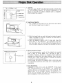
1
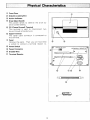
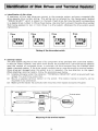
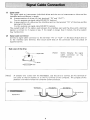
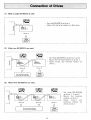
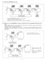
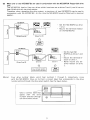
INSTRUCTION MANUAL
-
/'
Note for Users in U K
IMPORTANT
The wires in the mains lead of this apparatus are coloured in accordance with the
following code:
BLUE:
BROWN:
Neutral
Live
As the colours of the wires in the mains lead of this apparatus may not
correspond with the coloured markings identifying the terminals in your plug,
proceed as follows:
* The wire which is coloured BLUE must be connected to the terminal
which is marked with the letter N or coloured BLACK.
* The wire which is coloured BROWN must be connected to the terminal
which is marked with the letter L or coloured RED.
INSTRUCTION
Thank you for purchasing the SHARP Floppy Disk MZ-80SFD. It is a peripheral unit for use with
the SHARP Personal Computer which can operate a maximum of 4 drives. We believe that it will be
very useful as an external memory unit because of its large capacity and high speed access.
Read this instruction manual carefully before using the Floppy Disk so you can use it correctly.
•
•
•
•
•
•
•
•
Page
Precautions .............................................. 1
Physical Characteristics ..................................... 2
Identification of Disk Drives and Terminal Resistor ............... 3
Signal Cable Connection .................................... 4
Connection of Drives .... . . . . . . . . . . . . . . . . . . . . . . . . . . . . . . . . . .• 5
Floppy Disk Operation ..................................... 8
Handling the Diskette ...................................... 9
Specifications ...............................•............ 10
3
1
Precautions
• Terminal resistor
Which drive must or must not be fitted with a terminal resistor is dependent on the combination or number of drives to be used. For prevention of troubles, every drive leaves our plant with
any terminal resistor not attached. When mounting a terminal resistor, read the directions given
later carefully and attach the resistor to a right drive. I mproper attachment could cause damages to
connected drives.
• Upgrading the drive system
A maximum of four MZ-80SFDs can be used in daisy-chain connection or the MZ-80FB or
MZ-80FB K- an extension drive unit for the MZ-80FB- can be used in conjunction with one
or two MZ-80SFDs to upgrade the drive system. When upgrading the drive system, interconnect
necessary drives in the specified manners shown later. Incorrect interconnection will destroy the
drive signal circuit.
• Connection with the computer system
When connecting any drives to the computer system, be sure to switch off the whole system in
advance.
• Power supply
Be sure to use a supply voltage that is shown on the rating plate attached to the back of the
MZ-80SFD. The use of any other supply voltage causes damages to the drive. Also, never connect
the MZ-80SFD to the same electrical outlet where some apparatus that generates a noise - a
heavy-duty motor, etc. - is connected, otherwise the system could malfunction.
• Humidity and dust
The MZ-80SFD, a precIsion engineered gadget, dislikes an excessive humidity. Avoid using this
drive in a location that is subject to high humidity or exposed to much dust.
(Ambient humidity = 20 to 80%)
• Installation requirements and impact
The MZ-80SFD is composed of precision engineered mechanisms and electronical components.
Use it in a location that is not subject to an extreme high or low temperature, abrupt temperature
changes, or heavy vibration or exposed to much dust. Never give any unreasonable impact to this
device by putting something on it or dropping it by mistake. Also, never place it near a speaker,
TV set, or tape recorder because these are generating magnetism. This will cause malfunction ef
the drive or delete data or texts stored in a diskette.
Never operate the MZ-80SFD slanted. This will impede correct writing or reading.
Also, place the signal cables of the system kept as far away as possible from the other associate
devices and the power cords.
• Power cord
Be careful not to place a desk or chair on the power cord or catch it in anything, otherwise the
cord could be damaged. The use of a damaged power cord leads to hazard. When disconnecting the
power cord, be sure to pull it off by holding the plug.
• When the MZ-80SFD is expected not to be operated over an extended period of time
Be sure to disconnect the power cord from the electrical outlet.
• Stain
If the machine is contaminated, gently wipe it with soft cloth soaked in water or cleaning fluid.
Neither use any volatile chemicals such as benzine and thinner nor spread insecticide on the
machine. This will result in discoloration of the cabinet.
1
Physical Characteristics
CD
®
Front Door
Diskette Loading Slot
@ Action Indicator
@ Drive Select Switch
This switch serves to identify the drive by
drive number setting.
@ FG (Frame Ground) Terminal
This terminal is used to interconnect two
drives through a braided wire.
@ Signal Terminal
The signal cable connector is connected to
this terminal.
c=J) Panel
Remove the panel. Then you will find there
a socket to connect a terminal resistor to.
@ Power Switch
DRIVE SELECT
@ Power Connector
®
®
TERMINAL RESISTOR@
Braided Wire
Terminal Resistor
@
2JL--'!~~~~~~~!l.....JLS
®
11
2
Of Disk Drives and Terminal R••lstor
• Identification of disk drives
A maximum of four disk drives can connect to the computer system, and every connected disk
drive requires drive number setting. This setting can be achieved by the 4-gang switch labelled
"DR IVE SE LECT" which is present on the back of each drive. Set only the switch corresponding
to a desired drive number to ON as shown below. Use care then to prevent the same drive number
from being assigned to two or more drives in a drive system, otherwise the drive system would
malfunction.
Drive
Drive
1
2
~.1 2
s 41~
N~~~~
Drive
Drive
S
01 2 S
p.J 2 S 40
N[;]~~~N
4
4.9
N~~~[;]N
01 2 S 40
N[;]~~~N
Setting of the drive select switch
• Terminal resistor
The drive system requires to have one of its component drives provided with a terminal resistor.
It must be noted, however, that which drive should be provided with a terminal resistor depends
upon the number of connected drives. In principle, the drive remotest from the interface alone
needs a terminal resistor. If the drive system contains two or more drives with a terminal resistor,
those drives get damaged when the system is put in operation. Pay due attention to this regard.
When attaching a terminal resistor, follow the procedure given below.
(1) Unscrew the panel under the indication "TERMINAL RESISTOR" which is secured with two
screws. You will find a socket then.
(2) Mount a supplied terminal resistor on the socket. This resistor, having no polarity, can be
mounted in any orientation.
(3) Make sure the resistor has correctly been mounted, then replace and screw the panel.
DRIVE SELECT
~
=
TERMINAL RESISTOR@
Terminal resistor
· ·•·•·•·•
\)A
•••••••
"'" IN ' -_ _ _ _--/
0(.'·······
o (:: .'. ".... -·.·.·.·::)OOUT
FG
@
POWER
OFF ON
I
o
se I
Mounting of the terminal resistor
3
(1)
Signal cable
The signal cable to interconnect individual drives and the one to interconnect a drive and the
interface card are different in length.
(a) Interconnection of drives (or their terminals "IN" and "OUT")
For this purpose use signal cable MZ-80FCK (option).
(b) Interconnection of a drive and the interface card (or the terminal "IN" of the drive and the
terminal of the card)
For this purpose use signal cable MZ-80FC (option).
The overall length of the cables used between the interface card and the drive with a terminal
resistor is limited to 3 meters or less. If the length is longer than 3 meters, the drive system
may malfunction.
(2)
Signal cable connection
Connect a signal cable connector to the terminal "I N" or "OUT" on the back of each drive or
to the interface card terminal, then secure both ends of the connector with two pieces of
suppl ied screws.
Back view of the drive
(Note)
,...,...-----Signal cable
Screw likewise the signal
cable connector on the
interface card.
Screw
~@:::::::::::::~
[Note]
OUT
A braided wire comes with the MZ-80SFD. Use this wire to connect the FG terminal of
one drive to that of another or to the FG terminal of the computer. The purpose of this
practice is to reduce noises the computer system produces.
(Computer)
Braided wire
(MZ·80SFD)
(MZ.80SFD)
_~""'d';."
4
(1)
When a single MZ-80SFD is used:
• Set the MZ-80SFD as drive 1.
Mount the terminal resistor on this drive.
Q)
()
-t
Q)
C
IN
c:::::::J 0 U T
(Drive 1)
(2)
When two MZ-80SFDs are used:
Set these MZ-80SFDs as drives 1 and 2.
Mount the terminal resistor on drive 1.
• Never mount any terminal resistor on
drive 2.
Q)
()
-t
~
c
(Drive 1)
(Drive 2)
(3)
When three MZ-80SFDs are used:
Q)
()
co
1:
~
c
(Drive 3)
(Drive 2)
(Drive 1)
Any term inal resistor
must not be mounted.
5
Set these MZ-80SFDs
as drives 1, 2, and 3.
Mount the terminal
resistor on drive 1.
Never
mount
any
terminal resistor on
drives 2 and 3.
(4)
When four MZ-80SFDs are used:
(Drive 3)
(Drive 4)
(Drive 1)
(Drive 2)
Any term inal resistor
must not be mounted.
• Set these MZ-80SFDs as drives 1,2, 3, and 4.
Mount the terminal resistor on drive 1.
Never mount any terminal resistor on drives 2 through 4.
(5)
When one or two MZ-80SFDs are used in conjunction with the MZ-80FB floppy-disk drive
unit:
The MZ-80FB (option) has two drives which have been set as drives 1 and 2; and it has been
already provided with a terminal resistor.
Therefore, when upgrading the drive system, a maximum of two MZ-80SFDs can be used in
conjunction with the MZ-80FB. At this time no terminal resistor must be mounted on any
MZ-80SFD.
Set the MZ-80SFD as drive 3.
Never mount the terminal resistor.
Q)
u
t
Q)
c
(Drive 3)
(Drives 1 and 2)
MZ-80FB
Set
the two MZ80SFDs as drives 3 and
Q)
u
t
4.
~
c
(Drive 4)
(Drives 1 and 2)
(Drive 3)
Any term inal resistor
must not be mounted.
6
Mount any terminal
resistor on neither of
these drives.
(6)
When one or two MZ-80SFDs are used in conjunction with the MZ-80FBK floppy-disk drive
unit:
The MZ-80FBK (option) has two drives which have been set as drives 3 and 4; and it has not
been fitted with any terminal resistor.
Therefore, when upgrading the drive system, a maximum of two MZ-80SFDs can be used in
conjunction with the MZ-80FBK. At this time the MZ-80SFD must be fitted with a terminal
resistor.
MZ-BOFBK
t~~~~
Set the MZ-80SFD as drive
1 or 2.
Mount the terminal resistor
on the MZ-80SFD.
0'
IN
c:::::J OUT
(Drives 3 and 4)
(Drive 1 or 2)
MZ-BOFBK
Set the two MZ80SFDs as drives 1 and
.,u
~.,
...
2.
Mount the terminal resistor on drive 1.
• Never mount any terminal resistor on drive
c:
(Drives 3 and 4)
2.
[Note]
Four drive number labels, which bear numbers 1 through 4, respectively, come
with the MZ-80SFD. Glue on its front a correct label that corresponds to the drive
number setting through the drive select switch. See the figure below.
-----
Glue a correct Iabel that
agrees with th e drive
number selected through
the drive select switch.
--W
III
@
7
r--133.3mm
rD
-----I
Write-protection
/notch
E
E
Center hole
1 Diskette
This unit uses a 5.25" mini-disk that records on both sides
as the recording medium. Its external appearance is as
shown on the left. It's called a diskette and is a magnetic
sheet covered by a jacket.
M
M
-
Index hole
M
l
0
Head window
2 Inserting a Diskette
1. Put a finger on the bottom of the front door and lightly
put this door toward you to open it.
2. With the label side up and the head window forward,
insert a diskette in the slot. There is no other way to
insert a diskette correctly.
3. Push the diskette lightly until it stops and close the
front door. If the diskette is not inserted all the way,
the front door wi II not close. When this happens do not
force the door closed but re-insert the diskette correctly.
Diskette with write-protection.
G. . . .
Protection seal.
3 Write-protection Notch
If the write-protection notch of the diskette is covered
with a seal of silver paper, etc., writing of data is
forbidden. Reading, however, is possible. Some diskettes
supplied by Sharp that are called Masters have this part
covered with a seal. Never remove it because it prevents
trouble from improper operation.
Do not cover the notch of a diskette that is ordinarily used
for read/write operations with a seal, etc. or writing will be
i mpossib le.
4 Data Read/Write
Operation of this unit is only by ON/OFF of the power
and insertion/removal of a diskette. All reading and
writing of data is controlled by the host computer. For
details refer to the software manual. A maximum of 4
drives can be operated and drives are designated by the
drive numbers on the front of the unit.
8
Do not touch, soil or scratch the recording surface (Head
Window) of the diskette with your finger. This may cause
improper operation or result in no operation.
Do not bend or fold the diskette or it will become unusable.
Do not bring magnetic things near the diskette or the
contents of the diskette will be destroyed. In addition, it's
dangerous to bring a diskette near machines (motors, etc.)
that generate a magnetic field.
Fill in the index label before pasting it on the jacket or use a
soft pointed pen. If you use a ball-point pen or other hard
object on a label already pasted on the jacket, the diskette
will be damaged.
When not using a diskette, put it in an envelope and file it
away. This also prevents trouble caused by scratches and
dust.
~
Envelope
Storage temperatures for the diskette are 4°( to 53°(. Do
not leave the diskette exposed to direct sunlight, or locate it
in a place subject to the temperatures exceeding 53°(. This
may cause the jacket to be deformed and unusable.
When using the diskette, ensure that the temperature range
described on the protective envelope is observed. Environmental conditions may differ between the storage and operation places. This requires the diskette to be placed under the
proper operating environment for a while before use.
9
SpeCifications
Drive-to-drive connection:
Recording medium:
Recording:
Number of tracks:
Sector:
Formatted capacity:
Power supply:
Power Consumption:
Operating conditions:
External dimensions:
Weight:
Daisy-chain system (a maximum of four drives)
5.25-inch both-sides flexible disk
Double or single density
70 tracks
Soft sectored
280K bytes/drive at 16 sectors/track (double density)
140 K bytes/drive at 16 sectors/track (single density)
As shown on the rating plate (This plate bears a voltage value "AC
220V," "AC 240V," or others: Be sure to confirm it carefully.)
30W
5 to 25°C in temperature
20 to 80% in humidity (free of moisture condensation)
Approx. 165(W) x 102(H) x 323(0) mm
4 kg
*Specifications and design subject to change without prior notice for product improvement. In
such cases, items mentioned above may be partially different from the product.
*This apparatus complies with requirements of EEC directive 76/889/EEC.
10
SHARP CORPORATION
- - - - - - - -
Code:
MZ8XM02E
TINSE0040PAZZ
811120-0500-K
Printed in Japan
MZ-80SFD
E1