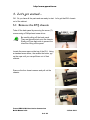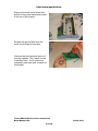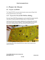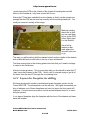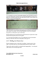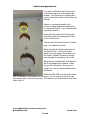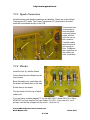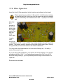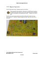
1
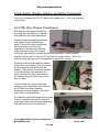
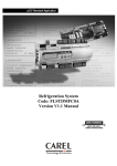
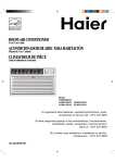
http://www.ppwatt.com
Tweed 5E3
PCB
Valve Junior Conversion
Build Manual
Tweed 5E3 PCB Valve Junior Conversion
Build Manual v3.0
1 of 40
13 Feb 2011
http://www.ppwatt.com
1. Introduction
This manual contains instructions to convert an Epiphone Valve Junior, Harley
Benton GA-5 or Legacy Valve Edition into a 14-18 watt Push Pull tube amplifier
modeled after the legendary Fender Deluxe Model 5E3 (AKA Tweed Deluxe
5E3). The heart of the amp is the Tweed 5E3 PCB, which conveniently lays out
the circuit in a printed circuit board, PCB, package.
This manual provides instruction for the assembly of version 3.3 & 3.4 of the
Tweed 5E3 PCB.
To simplify things,
x The Epiphone Valve Junior, GA-5 & Legacy Valve Edition will collectively
be referred to as the EVJ or VJr
This manual guides you through the conversion which includes:
x removing the stock EVJ chassis from its cabinet,
x extracting the stock EVJ PCB,
x drilling the chassis,
x assembling the Tweed 5E3 PCB,
x installation and hookup of the Tweed 5E3 PCB into the EVJ chassis,
x initial power-up and testing, and
x re-installing the chassis back into the EVJ cabinet to finish up the job.
+HUH¶VWKH7ZHHG(3&% v3.3.
Whilst it is labeled 9HUVLRQLWLVWKHILUVWµSURGXFWLRQ¶UHOHDVHRIWKHERDUG
There were a number of prior prototypes that led to this.
Tweed 5E3 PCB Valve Junior Conversion
Build Manual v3.0
2 of 40
13 Feb 2011
http://www.ppwatt.com
+HUH¶VWKHY3&%
7KH\¶UHYHU\VLPLODU7KHQHZHU3&%LVDOLWWOHQDUURZHUDOORZLQJLWWRILWPRUH
easily in VJr chassis.
They also work really well as the basis for a scratch build in a 16x8x2 chassis.
2. Electrical Shock Warning
Building tube amplifiers involves working with, or
around, high voltages. Working inside a tube
amplifier can be dangerous if you don't know the basic safety practices. Building,
modifying, or repairing tube amplifiers should only be performed by trained
personnel.
Tweed 5E3 PCB Valve Junior Conversion
Build Manual v3.0
3 of 40
13 Feb 2011
http://www.ppwatt.com
3. Disclaimer of Liability
PPWatt.com assumes no liability or responsibility, under any circumstance, for
personal injury or damage to property or personal property.
PPWatt.com reserves the right to make design changes or improvements without
obligation to revise prior versions.
All specifications are subject to change without notice.
The Tweed 5E3 PCB by PPWatt.com is licensed under a Creative Commons
Attribution-Share Alike 3.0 United States License.
Tweed 5E3 PCB Valve Junior Conversion
Build Manual v3.0
4 of 40
13 Feb 2011
http://www.ppwatt.com
Table of Contents
1. Introduction ................................................................................................................. 2 ............................................................................................................................................. 3 2. Electrical Shock Warning ........................................................................................... 3 ............................................................................................................................................. 4 3. Disclaimer of Liability ................................................................................................ 4 4. Project Overview ........................................................................................................ 7 4.1 +HUH¶VZKDW\RX¶OOQHHG ...................................................................................... 7 4.1.1 Parts: ............................................................................................................. 7 4.1.2 Tools: ............................................................................................................ 7 4.1.3 Supplies:........................................................................................................ 7 5. /HW¶VJHWVWDUWHG« ....................................................................................................... 8 5.1 Remove the EVJ chassis ...................................................................................... 8 5.2 5HPRYHWKH(9-¶V6WRFN&RPSRQHQWV ................................................................ 9 5.2.1 Remove the Tubes and Tube Retainers ........................................................ 9 5.2.2 Remove the Output Transformer from the Chassis ...................................... 9 5.2.3 Clean up the Power Transformer ................................................................ 11 5.2.4 Remove the Volume Potentiometer ............................................................ 12 5.2.5 Remove the Stock EVJ Circuit Board ........................................................ 12 6. Prepare the Chassis ................................................................................................... 14 6.1 Layout and Drill ................................................................................................. 14 6.1.1 Layout the Tweed 5E3 PCB for Drilling .................................................... 14 6.1.2 Layout the Faceplate for drilling................................................................. 15 6.1.3 Drilling the Chassis base ............................................................................. 16 7. Tweed 5E3 PCB ........................................................................................................ 18 7.1 Assemble the Tweed 5E3 PCB .......................................................................... 18 7.1.1 PCB Standoffs ............................................................................................. 19 7.1.2 Tube Sockets ............................................................................................... 19 7.1.3 Spade Connectors........................................................................................ 21 7.1.4 Diodes ......................................................................................................... 21 7.1.5 7KH³&DVFDGH3UHDPS´RSWLRQ .................................................................... 22 7.1.6 The Jumpers ................................................................................................ 22 7.1.8 Filter Capacitors .......................................................................................... 22 7.1.9 Bypass Capacitors ....................................................................................... 24 7.1.10 Install the Remaining Components ............................................................. 25 7.1.11 Input Jack complex ..................................................................................... 27 7.1.12 Tone & Volume Potentiometers ................................................................. 28 7.1.13 Connect the Control Leads.......................................................................... 29 8. Putting it all together ................................................................................................. 30 8.1 Install the New Components .............................................................................. 30 8.1.1 Hookup the Tweed 5E3 PCB ...................................................................... 30 8.1.2 The New Output Transformer .......................................................................... 32 8.1.3 The Power Supply connections ........................................................................ 34 Tweed 5E3 PCB Valve Junior Conversion
Build Manual v3.0
5 of 40
13 Feb 2011
http://www.ppwatt.com
9. Turn on the Power ..................................................................................................... 36 9.1 Check Your Work .............................................................................................. 36 9.1.1 Take a Break ............................................................................................... 36 9.1.2 Visual Inspection ........................................................................................ 36 9.2 Power Up without Tubes .................................................................................... 37 9.2.1 The First Power Up ..................................................................................... 37 9.3 Power Up with Tubes ......................................................................................... 39 9.3.1 The Real Test .............................................................................................. 39 10. Finish Things Up.................................................................................................... 40 10.1 Re-Assemble the Amp .................................................................................... 40 Tweed 5E3 PCB Valve Junior Conversion
Build Manual v3.0
6 of 40
13 Feb 2011
http://www.ppwatt.com
4. Project Overview
<RX¶OOILQGWKDWWKLVLVDIXQSURMHFWWKDWFDQEHFRPSOHWHGE\DQ inexperienced
builder in a day or two.
This manual has been put together specifically for the novice builder. So,
DQ\RQHFDQGRLW5HDOO\LW¶VVLPSOHDQGLWGRHVQ¶WUHTXLUHH[SHQVLYHWRROVRU
complex equipment. Even an experienced builder will get value out of reading it
WKURXJK&¶PRQ,VSHQWDJHVZULWLQJWKLV
4.1 +HUH·VZKDW\RX·OOQHHG
4.1.1 Parts:
x
x
The Tweed 5E3 PCB
Misc. parts and components (refer to the Tweed 5E3 PCB parts list
document for a full listing of what parts are needed and where you
can buy them)
4.1.2 Tools:
x
x
x
x
x
x
x
x
Phillips head screw driver
Standard screw driver
Needle nose pliers
Adjustable wrench
Power drill (corded or cordless)
´´´1/2" Metal cutting drill bit
8QLELWVWHSELWRUSXQFKWRGULOOWZRó´PPRQHô´PP
holes)
Soldering iron (30-40 watt power rating)
4.1.3 Supplies:
x
x
Fluxed solder
Roughly 6 ft. 600v rated wire (22-18 AWG)
Tweed 5E3 PCB Valve Junior Conversion
Build Manual v3.0
7 of 40
13 Feb 2011
http://www.ppwatt.com
5. /HW·VJHWVWDUWHG«
OK. So you have aOOWKHSDUWVDQGDUHUHDG\WRVWDUW/HW¶VJHWWKDW(9-FKDVVLV
out of the cabinet.
5.1 Remove the EVJ chassis
Take off the back panel by removing the seven (7)
screws using a Phillips head screw driver.
Be careful pulling off the back panel.
They are typically stuck onto the chassis.
Slowly pull from each side to prevent the
tolex from lifting off the panel.
Locate the screw caps on the top of the EVJ. Using
a standard screw driver, the smaller the better, pry
up the caps until you can pull them out of their
sockets.
Remove the four chassis screws and pull out the
chassis.
Tweed 5E3 PCB Valve Junior Conversion
Build Manual v3.0
8 of 40
13 Feb 2011
http://www.ppwatt.com
5.2 5HPRYHWKH(9-·V6WRFN&RPSRQHQWV
A few of the stock EVJ parts have to be replaced. The tubes, tube retainers, and
stock circuit board need to be removed.
5.2.1 Remove the Tubes and Tube Retainers
,W¶VDVVLPSOHDV
x lift the tube retainer off the power tube,
x turn the retainer shield until the spring lifts the shield off the per-amp tube,
x pull the tubes out, and
x unclip the power tube retainer.
These items can be discarded. They will not be used later in the build.
Now that the tubes and their hardware have been
removed we can take a look inside. This is a version 2
EVJ. You can tell by the green board and the rectified
DC heater supply. Version 3s have a black board.
5.2.2 Remove the Output Transformer from the Chassis
To remove the output transformer,
disconnect its wire leads from the
main amp circuit board and the
output jack circuit board.
Pull these two spade connectors
from the main circuit board.
<RXGRQ¶WQHHGWRODEHOWKHOHDGV
since ZH¶UHJRLQJWRXVHD
Push/Pull OT in the build rather
than the Single Ended OT used
in a VJr.
However, you might want to label them (Input 1,Input 2, 4 out, 8 out, 16 out &
Ground) just in case you want to use it in another SE build at a later time.
Tweed 5E3 PCB Valve Junior Conversion
Build Manual v3.0
9 of 40
13 Feb 2011
http://www.ppwatt.com
,¶YHQHYHUERWKHUHG,W¶Van OK OT DVORQJDV\RX¶UHXVLQJD9(SL, but the
earlier versions are really not so good.)
Unscrew the output jacks from the chassis and
separate the board from the chassis. The board
will be glued to the chassis.
It may require some extra work to pick the glue
off. Be careful not to damage the board or the
output jacks. They will be reused later.
Flow the solder to each transformer lead on the
output jack board and pull the lead out. Remove
the fastening nut at the star grounding post and
remove the output ERDUG¶VJURXQGZLUH
Clean up any remaining solder off the board to
assist in the installation of the new transformer
later in the build. Now that all of the leads are
free, remove the mounting bolts to seperate the
transformer from the chassis.
Keep the nuts & bolts. We use them for the new
OT.
Keep the
output jack
ERDUGZLWKLW¶V
ground wire
attached.
The new OT you are going to use will need a new chassis mounting hole as it is
almost certainly going to be larger than the stock VJr one.
Continue to use the hole closest to the edge of the chassis, and mark where the
new one needs to be drilled. You could drill it now, or do it along with the rest of
the drilling later.
Tweed 5E3 PCB Valve Junior Conversion
Build Manual v3.0
10 of 40
13 Feb 2011
http://www.ppwatt.com
5.2.3 Clean up the Power Transformer
7KHVWRFN(9-¶VSRZHUWUDQVIRUPHUSURYLGHVOHDGVIRUYDULRXVPDLQVVXSSO\
voltages. The extra leads are fastened to dead posts on the stock circuit board
for storage. We are going to clean up the inside of the chassis by pulling any
unused power transformer leads outside of the chassis cavity.
Disconnect these three (3) leads from
the stock EVJ circuit board.
Version 1 and 2 EVJ will
have 12v secondary taps
tied off and tucked inside the
chassis. These need to be
pulled outside and secured
as well.
After the leads are all pulled outside
the chassis, bundle them together and
tie them off.
<RX¶OOKDYHWRXQVFUHZWKH37IURPWKH
chassis to provide enough room to use
the PCB as the drill hole guide.
If you have the money we strongly
advise you to buy a more suitable PT
than the stock unit.
A 300 - 325v CT @ 125mA+ PT will
give you a far better sounding amp.
Tweed 5E3 PCB Valve Junior Conversion
Build Manual v3.0
11 of 40
13 Feb 2011
http://www.ppwatt.com
5.2.4 Remove the Volume Potentiometer
Unscrew the fastening nut from the volume
potentiometer.
Pull the volume pot back into the chassis. Leave it
connected to the stock EVJ circuit board.
The volume pot will be glued to the
chassis. This part will NOT be used later
in the build, so use whatever force you
need.
5.2.5 Remove the Stock EVJ Circuit Board
Disconnect these four (4) leads from
the stock EVJ circuit board.
Lift the ground wire from the star
ground post.
Unplug the input jack wire at the circuit
board.
Remove the six (6) screws fastening
the circuit board to the chassis.
.HHSWKHP<RX¶OOXVHWKHPWRDWWDFK
the new PCB.
Tweed 5E3 PCB Valve Junior Conversion
Build Manual v3.0
12 of 40
13 Feb 2011
http://www.ppwatt.com
Remove the stock circuit board and
pull all of the power transformer leads
to the rim of the chassis.
Salvage the ground wire from the
stock circuit board for use later.
Unscrew the input jack and remove it
from the chassis. Set it aside for use
LQDQRWKHUEXLOG<RX¶OOFRQVWUXFWD
completely new input jack complex for
this project.
Tweed 5E3 PCB Valve Junior Conversion
Build Manual v3.0
13 of 40
13 Feb 2011
http://www.ppwatt.com
6. Prepare the Chassis
6.1 Layout and Drill
The Tweed 5E3 PCB, and control potentiometers require some drilling of both
the front panel & bottom of the chassis.
6.1.1 Layout the Tweed 5E3 PCB for Drilling
Since the Tweed 5E3 PCB was designed to use the stock EVJ chassis standoffs,
one method to mark the additional chassis holes is to install the board.
Lay the circuit board in the chassis, align the stock mounting studs, and install
two or three screws to fasten the board. With the board aligned to the chassis,
mark the two additional stand-off & tube socket drill locations as shown.
You will also drill out the existing EL84 hole to make it wide enough for the
second octal base.
Tweed 5E3 PCB Valve Junior Conversion
Build Manual v3.0
14 of 40
13 Feb 2011
http://www.ppwatt.com
I prefer laying the PCB on the outside of the chassis & marking the new drill
holes on the outside as I only have a hand drill to use.
Notice the PT has been unbolted from the chassis so that it can be moved over
enough that the PCB can be lined up correctly with the existing stand-offs. You
could just remove it entirely at this stage.
Mark the existing
stand-offs so that
you can use them
to line up the PCB
& then lightly tape
it to the chassis.
Use a felt tip
marker to then
mark where the
new drill holes are
to go.
This way you will be able to drill the chassis holes from the outside of the chassis
with a hand drill and not drill holes in the top of your workbench!
7KHEOXHDUURZSRLQWVWRWKHH[LVWLQJSRZHUWXEHKROHWKDW\RX¶OOQHHGWRHQODUJH
to cater for the Octal base.
Note the circled grommet. This is a new hole that you should drill to take the OT
µLQSXW¶ZLUHVWKDWFRQQHFWWRWKH3&%,ILQGLWDELWRIDVTXDVKWU\LQJWRJHWDOORI
the wires from the new OT through the one existing hole.
6.1.2 Layout the Faceplate for drilling
We have developed a number of professional grade faceplate options for the
Tweed 5E3 PCB. The information is on the web site. We highly recommend you
buy or fabricate one of these faceplates and use it to layout the front panel drill
ORFDWLRQV,W¶VPXFKPRUHDFFXUDWHWRXVHWKHDFWXDOIDFHSODWHWKDQLWLVWRXVHD
drill plan printout.
If you have a faceplate, align the faceplate with the front of the chassis and trace
each drill location.
Tweed 5E3 PCB Valve Junior Conversion
Build Manual v3.0
15 of 40
13 Feb 2011
http://www.ppwatt.com
If you are going to use one of the faceplate designs & get it fabricated yourself at
\RXUORFDO7URSK\6WRUHEXWKDYHQ¶WJot it yet) and are desperate to drill the front
panel you could print a copy from your Laser printer & stick it on the chassis front
instead of using the actual plate itself.
I find I still need to use my Dremel (with grinding stone bit fitted) to get the drill
KROHVµSHUIHFW¶HYHQZKHQ,XVHWKHDFWXDOIDFHSODWHVRGRQ¶WEHWRRVWUHVVHG
doing this if you really want to get on with things.
Affix the printed copy to the chassis with a generous amount of glue stick or tape.
Drill the holes using the print out as the guide.
,I\RXDUHXVLQJWKHUHDOSDQHORQFH\RX¶YHPDUNHGWKHFLUFOHVRQWKHFKDVVLV
where you will need to drill, remove the panel, & then go for it.
6.1.3 Drilling the Chassis base
Start by setting the center of each hole to be drilled. A center punch is often
XVHG,I\RXGRQ¶WKDYHRQHXVHDUHDOO\VPDOOGULOOELWILUVWWRVHWWKHµFHQWUH¶
7KHQXVHWKHµULJKW¶VL]HGULOOELWWRHQODUJHWKHKROHDSSURSULDWHO\,XVHDVWHSELW
(AKA Unibit) to do the really large holes.
Tweed 5E3 PCB Valve Junior Conversion
Build Manual v3.0
16 of 40
13 Feb 2011
http://www.ppwatt.com
You want to drill the Noval (9-pin) holes
VRWKDWWKHVRFNHWµOLS¶UHVWVDJDLQVWWKH
chassis. The Octal (8-pin) socket holes
need to allow the socket to slip all the way
through.
Deburr or countersink each hole to
ensure no sharp edges will cause injury
or component failure. I use a Dremel with
a grinding stone bit.
Notice that the existing VJr EL84 power
tube hole needs to be enlarged to cater
for the Octal socket.
7KHVHFRQG2FWDOVRFNHWKROHLVQ¶WVKRZQ
KHUH,W¶VVWDUWHGIURPIUHVK
Make sure that the Octal sockets can fit
through the hole. The Noval socket
wants to rest up against the chassis, but
WKH2FWDOLVµWKLFNHU¶QHHGVWRDFWXDOO\
pass through for everything to fit nicely.
:KHQGRLQJDVFUDWFKEXLOGERWK1RYDO¶V
will fit snug against the chassis. When
doing a VJr conversion, the second is
JRLQJWREHµIUHH¶DVWKHSUH-drilled hole is
quite wide.
Whilst the 5E3 PCB uses the stock standRIIVWKHFLUFOHGRQHVWLOOQHHGVWREHUHPRYHG,W¶VWRRFORVHWRWKHKROHIRUWKH
first noval socket. DRQ¶WZRUU\WKRXJK:HDGGWZRPRUHVWDQG-offs to more than
make up for it.
Tweed 5E3 PCB Valve Junior Conversion
Build Manual v3.0
17 of 40
13 Feb 2011
http://www.ppwatt.com
7. Tweed 5E3 PCB
7.1 Assemble the Tweed 5E3 PCB
7KHDQWLFLSDWLRQKDVEHHQNLOOLQJ\RXKDVQ¶WLW")LQDOO\WKHDVVHPEO\RIWKH
Tweed 5E3 PCB begins.
Did you check you make sure you have all of the
SDUWV\RX¶OOQHHGWRFRPSOHWHWKHDVVHPEO\"
I wish I did.
The graphics used in the assembly of this circuit board will NOT always
be an exact reflection of what your board will look like. Various parts
may have changed. The order of installation may vary from the picture
and this manual. Pictures were taken during various stages of the first
production build. This manual reflects the lessons learned during that build.
'RQ¶WQHFHVVDULO\XVHWKHSLFWXUHVWRFRPSDUHWKHprogress of your build. Follow
the instructions at each stage of the build and compare your work when the
manual specifically calls out a comparison check against a picture.
Tweed 5E3 PCB Valve Junior Conversion
Build Manual v3.0
18 of 40
13 Feb 2011
http://www.ppwatt.com
7.1.1 PCB Standoffs
Install the two (2) additional PCB standoffs on the back side of the board.
7.1.2 Tube Sockets
The tube sockets get installed on the back side of the board, too.
The tube sockets are installed as shown. The noval sockets only go in one way
(on the back side). However, the octal sockets need to be properly oriented with
the circuit board. Position the notch in these sockets so that they are pointing
toward the two noval sockets.
Do not solder them into the board yet !
,I\RXDUHGRLQJD9-UFRQYHUVLRQ\RXRQO\QHHGSXWLQWKHµILUVW¶QRYDO socket. If
you are doing a scratch build, put in both novals. Lift the PCB up into the chassis
guiding the tube socket(s) into the newly drilled out holes into the chassis.
Align the standoffs with their respective chassis holes and fasten them with a
couple of screws.
Now that the tube sockets are sandwiched between the circuit board and the
chassis, flip the chassis over and rest its top side (face down) on your work
bench.
We want to fit the socket(s) to the chassis drill holes. In a sense, it (they) will be
custom, or perfectly, fit to how you drilled the chassis.
Tweed 5E3 PCB Valve Junior Conversion
Build Manual v3.0
19 of 40
13 Feb 2011
http://www.ppwatt.com
7KHRWKHUVRFNHWVQHHGWREHµGURSSHG¶WKURXJKWKHFKDVVLVKROHVLQWRWKH3&%
pin connectors.
Make sure you orient the Octal socket the right way with the notch facing the
Noval sockets !
7DSHWKHVRFNHWVZLWKVWLFN\WDSHµIODW¶WRWKHFKDVVLV<RXDUHJRLQJWRLQYHUW
WKHFKDVVLVEDFNXSWRVROGHUWKHPRQWRWKH3&%VRLI\RXGRQ¶WWKHWXEH
sockets will fall back out again !
Try and tape the sockets such that when the tubes are installed, they will point up
QLFHVWUDLJKW,WZLOOORRNµQHDWHU¶
Flip the chassis. Sit it on a couple of blocks on your work bench so the sockets
DUHµIUHH¶VLWWLQJFRUUHFWO\ZLWKUHVSHFWWRWKHFKDVVLV. Solder the socket lugs to
the circuit board. The holes are through plated so the solder will flow into the hole
and through to the other side of the socket leg creating a very durable connection.
Use a fair bit of solder, but not too much. 7KLQNRIWKHWKUHHEHDUV«
If you just keep pushing solder into the joint it will run down the socket lug on the
other side of the board and may short out across a neighboring lug or run into the
socket itself.
When all of the socket lugs are soldered, remove the circuit board from the
chassis and touch-up any solder joints on the other side (or socket side).
Tweed 5E3 PCB Valve Junior Conversion
Build Manual v3.0
20 of 40
13 Feb 2011
http://www.ppwatt.com
7.1.3 Spade Connectors
Install the three male spade connectors as indicated. These are for the Output
Transformer (OT) leads. The Power Transformer (PT) high tension & heater
leads will be soldered directly to the PCB.
Extra solder time
is necessary to
heat the spade
connector before
solder will flow.
Hold the iron on
the connector.
Feed the solder
when the joint is
hot enough to
flow. Straighten
the connectors as
the solder joint
sets, or hardens.
7.1.4 Diodes
Install the four (4) rectifier diodes.
Orient the diodes as indicated on the
circuit board.
Bend the leads over, insert them into
the board, and bend them to the side.
Solder them to the board.
Trim the leads off at the top of each
solder pool.
If you are using a center-tapped PT, like the MPS 325.2, Weber 025130 or Edcor
XPWR107 \RXRQO\XVHWKHµILUVW¶WZRGLRGHV'',I\RXXVHDOO\RX¶OO
SXWZD\RYHUWKHWRSYROWDJHVLQWRWKHFLUFXLW«'RQ¶WGRLW
Tweed 5E3 PCB Valve Junior Conversion
Build Manual v3.0
21 of 40
13 Feb 2011
http://www.ppwatt.com
If you are XVLQJ7XEHUHFWLILFDWLRQ\RXGRQ¶WLQVWDOOWKH'LRGHV,QVWHDG\RX¶OO
FRQQHFWWKH+7ZLUHIURPWKHWXEHWRWKHµODUJH¶'SDG
7.1.5 7KH´&DVFDGH3UHDPSµRSWLRQ
The Tweed 5E3 PCB can be configured to have a cascaded V1 gain stage along
with many other configurations including tube tremolo & higher power 6L6
versions.
Look in the 5E3 section of PPWatt.com and ask for help from the friendly folk
over there ;-)
(There are many really cool options)
7.1.6 The Jumpers
Use 4 short pieces of insulated wire to connect the 3 jumper runs, J1, J2 & J3
and the V1 cathode connection.
'RQ¶WIRUJHWWKHMXPSHUWRFRQQHFWY¶VSLQV,
GLG«
The amp will still work for the Instrument channel, but
WKH0LFLQSXWVZRQ¶WSURGXFHDQ\VRXQG
Note the circled MXPSHUJRLQJIURPWKHµERWWRP¶VROGHU
pad of R11 to the nearby grounding pad.
You only use this if you DO NOT want a pair of Mic
channels but only want the 2 Instrument channels.
Tweed 5E3 PCB Valve Junior Conversion
Build Manual v3.0
22 of 40
13 Feb 2011
http://www.ppwatt.com
7.1.8 Filter Capacitors
Insert the four (4) filter capacitors in their locations as indicated on the board.
These capacitors are polarized. Be careful to install them by inserting
the positive lead (the longer one) into the square pad and the negative
OHDGDVLQGLFDWHGE\WKHGRZQZDUGDUURZDQG³-³V\PEROLQWKHround
pad.
Note that
C1 ±
pointed to
by the red
arrow, may
be a larger
capcity cap
than the
other 3
22uF caps.
I used a
33uF,
though you
could well use a 47uF or even a 100uF if you really wanted to though it would be
overkill. The greater capacity capacitor will provide slightly better power filtering;
though will also put more of a strain on the Power Transformer.
<RXPD\SUHIHUWKHFKDUDFWHULVWLFVRIDORZHUYDOXHILOWHULQJFDS,W¶VUHDOO\D
matter of personal choice.
If you are using tube rectification, your choices are more restricted. You should
SUREDEO\VWLFNZLWKDX)<RX¶GSUREDEO\JHWDZD\ZLWKDX)EXWDX)
ZRXOGEHUHDOO\SXVKLQJLW\RX¶GSRWHQWLDOO\FKHZWKURXJKUHFWLILHUWXEHVDWD
rapid rate.
Solder and trim the leads.
Tweed 5E3 PCB Valve Junior Conversion
Build Manual v3.0
23 of 40
13 Feb 2011
http://www.ppwatt.com
7.1.9 Bypass Capacitors
Install, solder and trim the 3 bypass capacitors as shown.
These capacitors are polarized. Be careful to install them by inserting
the positive lead (the longer one) into the square pad and the negative
lead (as indicated by the GRZQZDUGDUURZDQG³-³V\PEROLQWKHURXQG
pad.
1RWDOORIWKHFRPSRQHQWVLQWKLVSLFWXUHZLOOORRNOLNHZKDW¶VFDOOHGIRULQWKH
current parts list. I used 22uF bypass capacitors rather than the stock 25uF in
this build.
Tweed 5E3 PCB Valve Junior Conversion
Build Manual v3.0
24 of 40
13 Feb 2011
http://www.ppwatt.com
7.1.10 Install the Remaining Components
Install, solder and trim all of the remaining components in the circuit.
Refer to the latest
version of the schematic
or chassis layout
drawing on PPWatt.com
in the FAQ, the Tweed
5E3 PCB, and/or the
component package to
identify, locate and
position component
values.
If you have one of the
first batch of PCBs
(version 3.3) there is a
labelling error to two of
the components in the
bottom left.
No certain order needs
to be followed.
I generally do the
FRXSOLQJFDSVQH[W,W¶V
just a haELW,¶PLQ
N.B. C8 & C9
± the tone
control caps
are not
installed on the
PCB. They
are attached
between the
Tone &
Volume Pots.
Then do the
power resistors
Tweed 5E3 PCB Valve Junior Conversion
Build Manual v3.0
25 of 40
13 Feb 2011
http://www.ppwatt.com
Finally, the last of the resistors ! Note that R7 & R8 are not installed on the PCB.
They are part of the input jack complex.
I use metal film resistors for the 64K & 1M input resistors rather than carbon
FRPSV,W¶VMXVWSHUVRQDOSUHIHUHQFH,KDYHDEXQFKRIWKHPWKDW,ZDQWWRXVH
up !
+HUH¶VZKDWWKHILQLVKHG7ZHHG(3&%VKRXOGORRN like.
Tweed 5E3 PCB Valve Junior Conversion
Build Manual v3.0
26 of 40
13 Feb 2011
http://www.ppwatt.com
7.1.11 Input Jack complex
The VJr has only one input jack. The Tweed 5E3 has 4. You may as well make
the whole input jack complex with new materials. Save the original VJr input jack
for another project !
Look at the Chassis Layout
diagram to see how you are
going to wire together the
input jacks. I find it easier to
wire them together when
they are connected to the
outside of the chassis in their
actual mounting holes.
The first picture shows my
use of a different input jack to
WKHµVWDQGDUG¶FOLIIMDFNXVHG
on VJrs.
I used them because they
ORRNPRUHµDXWKHQWLF¶WRD
vintage 5E3 from the outside.
It happens to be stereo jack
with a DPDT switch mechanism. Took me ages to work out how to wire it
FRUUHFWO\«DQG,¶PVWLOOQRWVXUH,¶YHGRQHLWFRUUHFWO\
With conventional
cliff jacks, you will
end up with
something like
WKLV«
This is a picture
of the input jack
complex for the
prototype 5E3 I
assembled where
the 1M resistors
were on the PCB
± KHQFH\RXGRQ¶W
see them here.
Tweed 5E3 PCB Valve Junior Conversion
Build Manual v3.0
27 of 40
13 Feb 2011
http://www.ppwatt.com
:LWKP\³)HQGHULVK´ORRNLQJ
sockets it looks like this. Note !
7KLVLVQRWWKHµFRUUHFW¶ZLULQJ,
had to rewire it after doing some
WHVWLQJ«
Such are the trials & tribulations of
the hobby amp builder ;-)
8VHWKH³FOLII´MDFNV«7KH\¶UH
much easier to wire.
7.1.12 Tone & Volume
Potentiometers
I find the easiest way to wire the pots is to mount them on the chassis as well.
Use the layout diagram again to see how the lugs & the tone capacitors are wired
together.
Cut the tab off of each of the pots with a pair of cutters
(side cuts). A pair of pliers can also be used to bend
WKHWDERYHUDQGEUHDNLWRII7KDW¶VZKDW,GR
You should end up with it looking like this: This time ,GLGGRLWULJKWWKHILUVWWLPH«
Tweed 5E3 PCB Valve Junior Conversion
Build Manual v3.0
28 of 40
13 Feb 2011
http://www.ppwatt.com
7.1.13 Connect the Control Leads
Hooking up the circuit board is almost done. We now need to solder the wire
leads from the control potentiometers and input jack complex & the ground wire.
+HUH¶VZKHUHDOORIWKHOHDGconnections are.
The input jack wires connect to the pads marked in yellow.
The volume / tone pot wires connect to the pads marked in green.
The ground wire connects to the pad marked by the blue circle.
You should solder on the ground wire you salvaged earlier now.
This will be connected to the existing ground post. You will note that the mains
ground wire from the IEC connector also connects to this post. Some people say
it is better practice to have a separate ground for that wire than the star ground
for all the others.
If you do choose to use a separate ground, do NOT use one of the transformer
bolts. Personally, I just use the existing star ground.
Tweed 5E3 PCB Valve Junior Conversion
Build Manual v3.0
29 of 40
13 Feb 2011
http://www.ppwatt.com
The populated PCB is now ready to be placed in the chassis so that the leads
can be cut to their correct length & soldered to the PCB.
8. Putting it all together
8.1 Install the New Components
1RZWKDWHYHU\WKLQJLVRXWRIWKHFKDVVLVWKDWZHGRQ¶WQHHGWKHFKDVVLVKDV
been drilled, and the Tweed 5E3 PCB has been assembled, we can prep the
chassis and install all of the new components.
8.1.1 Hookup the Tweed 5E3 PCB
Place the circuit board into the chassis, align the mounting standoffs to their
respective chassis holes and lightly fasten the board to the chassis with a screw.
:H¶OOEHtaking it back out to solder the connecting wires)
Mount the pots inside the chassis as shown: Guide the wires from the pots to their respective solder pads on the PCB. Trim
the wires to length ± not too short, nor too long. You want them to end up nice &
neat.
Tweed 5E3 PCB Valve Junior Conversion
Build Manual v3.0
30 of 40
13 Feb 2011
http://www.ppwatt.com
Repeat the process with the Input Jack
complex. The two Instrument channel
wires & ground are short & connect at the
front of the PCB. The two Mic channel
wires are longer, and connect at the back.
Same principle applies though. Keep the
wires as short as possible ± but not too
short ;-<RXUHDOO\GRQ¶WZDQWWRUHGRRQH
RIWKHIO\LQJOHDGVEHFDXVH\RXFXWLWó´
too short !
Take the PCB, control pots & input jack
back out of the chassis & solder them
together.
It should look like WKHSLFWXUHDERYHZKHQ\RX¶UHGRQH
:H¶UHDOPRVWWKHUHQRZ«-XVWWKHSRZHUOHDGVVZLWFKHVWRJR«
Guide the PCB, Pots & Jacks back in & loosely fit them. They¶OOEHFRPLQJEDFN
out after this last lot of measuring & wire cutting.
Tweed 5E3 PCB Valve Junior Conversion
Build Manual v3.0
31 of 40
13 Feb 2011
http://www.ppwatt.com
Power Supply, Standby, Heaters, and Output Transformer
Have you connected the OT & PT back to the chassis yet ? If not, now would be
a good time !
8.1.2 The New Output Transformer
Relocate the extra power transformer
grommet from the left-front to the new
hole drilled for the output transformer.
Guide the leads through the grommets
and seat the output transformer in
place. Position the output transformer
with its primary to the front and
secondary to the back such that the
output wires go through the original
hole & the input wires go through the new hole as shown. I use a couple of
washers with the bolts to raise the OT up from the chassis a little. I find it sits
better this way with the wires not squashed up against the chassis.
Guide all of the wires through the chassis.
(Learn from our mistakes.) The extra wires
will be secured and stowed inside the
chassis. Their location outside the chassis
is too susceptible to the heat from the
tubes. Secure the output transformer to
the chassis using the stock nuts & bolts
that you kept !
Cut and solder the output transformer
leads onto the output jack board. Refer to
the PPWatt.com layout diagram,
transformer hookup diagram, and output
jack board for hookup details.
Re-Install the output jack board into its stock
location. Guide the ground wire from the
output jack board to the star grounding stud.
This will be secured to the stud later.
Tweed 5E3 PCB Valve Junior Conversion
Build Manual v3.0
32 of 40
13 Feb 2011
http://www.ppwatt.com
6ROGHUDµIHPDOH¶VSDGHTXLFNFRQQHFWWRHDFKRIWKHEURZQUHG27SULPDU\
µLQSXW¶ZLUHV
This shows the wire colours of the MPS OT15PP output transformer. The red is
the B+ lead (T8) & the brown are the 8K leads. The blue wires are the 7K taps.
Other OTs are likely to have different coloured wires.
The MPS OT20PP 8K tap is brown & blue & the 6.6K tap is white & grey.
8K is the recommended impedance, but you may prefer the sound from the lower
impedance WDSV,WZRQ¶WKXUWWKH27RUWXEHVDWWKHORZHUYDOXH You could
put them on a switch. Just make sure not to flick the switch with the amp on full
EODVW<RXFRXOGGDPDJHWKH27«
Twist the brown wires as shown & slide
the newly soldered spade connectors
onto the Tweed 5E3 PCB spade
connectors as shown.
Insulate & tie off the blue OT wires out of
the way.
Tweed 5E3 PCB Valve Junior Conversion
Build Manual v3.0
33 of 40
13 Feb 2011
http://www.ppwatt.com
8.1.3 The Power Supply connections
So close now !
We now need to connect the heater & main HT power to the PCB. These wires
DUHVROGHUHGGLUHFWO\WRWKH3&%1RµTXLFNFRQQHFWV¶IRUWKHVH
Again, neatness is important. If cleanliness is next to godliness, neatness is next
DJDLQ:HZDQWWKHVHµQRLV\¶ZLUHVZHOOWZLVWHGURXWHGZHOODZD\IURPWKH
circuitry.
$SLFWXUHSDLQWVDWKRXVDQGZRUGV«
The orange wires from the PT go to the heater pads. I route them from
underneath & up, soldering from the top side of the PCB. The thin wires you can
see soldered to these same pads go to the 6v Bezel. If you have a 120/240v
ODPS\RX¶GWDNHVRPHWDSVIURPWKHSRZHUVZLWFK
If you are using a stock 9-USRZHUVZLWFK\RXZRQ¶WERWKHUZLWKHLWKHURSWLRQ
Tweed 5E3 PCB Valve Junior Conversion
Build Manual v3.0
34 of 40
13 Feb 2011
http://www.ppwatt.com
7KHWZRUHGZLUHVIURPWKH37JRWRWKH+7SDGV77,WUHDOO\GRHVQ¶W
PDWWHUZKLFK:HGRQ¶WXVHQHJDWLYHIHHGEDFNLQWKLVFLUFXLW
If you are using the stock VJr power switch just solder a jumper between the
standby pads, T3 & T4. If you are using a Stand By switch, wire a pair of
connecting leads as shown.
When wiring the main power switch, remember that the main Active & Neutral
ZLUHVJRWRWKHµFHQWHUSRVWV¶on the switch, and the wires to the PT go from the
µRXWVLGH¶OXJV8VHWKHDSSURSULDWH37ZLUHVIRU\RXUFRXQWULHVYROWDJHV7KH
U.S. would use the 115v taps, yellow & black. Australia & most of Europe would
use the 240v taps, Brown & Black or 230v taps, Blue & Black)
Fasten the ground wires from the Tweed 5E3 PCB and the output transformer to
the star ground screw post.
Tweed 5E3 PCB Valve Junior Conversion
Build Manual v3.0
35 of 40
13 Feb 2011
http://www.ppwatt.com
Good Job!
<RX¶UHDOPRVWGRQH%XWEHIRUH\RXVWDUWFHOHEUDWLQJ\RXVWLOOKDYHWRUHYLHZ
your work, start it up and test the voltages.
9. Turn on the Power
9.1 Check Your Work
9.1.1 Take a Break
Now is a good time to take break. Rest your mind and gather your thoughts.
<RXGRQ¶WZDQWWREHWLUHGRUUXVKHGZKLOHSHUIRUPLQJWKHIROORZLQJVWHSV
9.1.2 Visual Inspection
When you are ready, step through the instructions in this manual again and verify
each step was performed and completed properly.
Look for the following:
x Missing components
x Damaged components or leads
x Solder joints that may have spilled over onto a nearby component or
solder pad.
x Loose connections.
x Stray bits of wire from trimming wire and/or components.
x Components or wire leads shorting against each other or the chassis.
Pay special attention to the volume and tone controls and the
sag resistor.
x
x
Check that the IEC mains power connector is equipped with a good fuse.
The fuse should be rated for 2A Slo-Blo. (1A with 230/240v Mains)
,I\RX¶YHXVHGD9-U37NHSWWKHKHDWHUWDSRUDQJHZLUHVIXVHFheck
its fuse. The fuse should be rated for no more than 4A Slo-Blo. I
SHUVRQDOO\GRQ¶WXVHDKHDWHUVXSSO\IXVHJHWULGRILW,¶PQRWFRQYLQFHG
that it serves a useful purpose. This fuse assembly is a common cause of
problems. Make sure there is continuity across it.
Tweed 5E3 PCB Valve Junior Conversion
Build Manual v3.0
36 of 40
13 Feb 2011
http://www.ppwatt.com
9.2 Power Up without Tubes
9.2.1 The First Power Up
Make sure you are working is a safe area free of any flammable
chemicals or vapors. An assembly error may result in the emission of
sparks.
The tubes should NOT be installed during the initial power up.
Plug the amplifier into a speaker cabinet. Match the speaker
impedance with the appropriate output jack. Failure to connect a
speaker will cause harm and eventual failure of the output transformer.
9HULI\WKHDPS¶VSRZHUVZLWFKLV LQWKH³2II´SRVLWLRQ,QVHUWWKHPDLQVSRZHU
cord in the IEC mains connector.
Secure the black ground lead of your voltmeter to the chassis star ground lug.
6ZLWFKWKHSRZHUVZLWFKWRWKH³21´SRVLWLRQ:LWK\RXUYROWPHWHUFKHFNWKH
following voltages. If a significant deviation from these readings is observed, turn
off the amp, unplug the mains power and investigate.
These measurements will read high since there is no load on the transformer.
Tweed 5E3 PCB Valve Junior Conversion
Build Manual v3.0
37 of 40
13 Feb 2011
http://www.ppwatt.com
The unloaded B+ voltage should measure the same all the way up the power rail.
A slight fluctuation is normal. If a difference greater than 5-10 Vdc is measured,
VRPHWKLQJLVGUDZLQJFXUUHQWZKHQLWVKRXOGQ¶W7XUQRIIWKHDPSDQG
troubleshoot the problem.
Turn OFF the amplifier.
Tweed 5E3 PCB Valve Junior Conversion
Build Manual v3.0
38 of 40
13 Feb 2011
http://www.ppwatt.com
9.3 Power Up with Tubes
9.3.1 The Real Test
Install the tubes!
$UHQ¶WWKH\SUHWW\"
9HULI\WKHDPS¶VSRZHUVZLWFKLVLQWKH
³2))´SRVLWLRQ,QVHUWWKHPDLQVSRZHU
cord in the IEC mains connector.
Secure the black ground lead of your
voltmeter to the chassis star ground lug.
Plug the amplifier into a speaker cabinet.
Match the speaker impedance with the
appropriate output jack. Failure to connect
a speaker will cause harm and eventual
failure of the output transformer.
6ZLWFKWKHDPS¶VSRZHUVZLWFKWRWKH³21´
position. With your voltmeter, check the
following voltages. Your voltages will be
different !
1RWH7KHSLFWXUHVKRZVYDW9¶V
pin 7. This is a mistake. Instead you
should find that probing here causes
µVFUDWFK\QRLVH¶RXWRIWKHVSHDNHU7KLVLV
the signal path.)
However they should be of the same order.
If a significant deviation from these
readings is observed, turn off the amp,
unplug the mains power and investigate.
To check the heater voltage you need to
measure across the two pads, where
VKRZQ<RXFDQ¶WFKHFNZLWKUHIHUHQFHWR
JURXQG,W¶VHOHYDWHG± by design.
,W¶V$&WRR
Turn the power off, disconnect the black
ground lead from the star ground lug, then
power back on & probe with the two. Be
FDUHIXO<RX¶OOSUREDEO\QHHGWRXVHERWKKDQGV
Tweed 5E3 PCB Valve Junior Conversion
Build Manual v3.0
39 of 40
13 Feb 2011
http://www.ppwatt.com
10. Finish Things Up
10.1 Re-Assemble the Amp
Slide the chassis back into the stock cabinet. Fasten the chassis to the cabinet
with the stock bolts. If you have used a StandBy switch in the position shown by
WKHIDFHSODWHV\RX¶OODOPRVWFHUWDLQO\KDYHWRXVHDVKRUWHUEROWWKDQWKHVWRFN
RQHLQWKDW³SRVLWLRQ´7KHVWRFNRQHPD\SXVKRQWRWKHVZLWFKVKRUW1DVW\
Others have had success replacing the standard bolt in this case with one known
DVDQ³M6 x 16 Pan Head machine screw´7KH\¶UHFKHDS«2WKHUZLVHMXVW
GRQ¶WXVHRQH<RX¶OOVWLOOKDYHRIWKHLQXVH6KRXOGEH2.«
Insert the bolt caps back into the sockets. Press them in until they are flush with
the cabinet surface. Attach the back panel with the stock screws.
Congratulations! Your have successfully converted your Epiphone Valve Junior
into a Tweed 5E3. Plug in a guitar and enjoy your new amp.
Tweed 5E3 PCB Valve Junior Conversion
Build Manual v3.0
40 of 40
13 Feb 2011