1
STULZ the natural choice
Instructions
CyberAir 3 CW
Precision Air Conditioning Units
380-415/3/50
Original instructions
Index 18
Issue 8.2011
Contents
1. Safety ...........................................................................................................................3
1.1 Marking..............................................................................................................................................3
1.2 Safety instructions .............................................................................................................................3
1.3 Safety and environmental requirements ............................................................................................4
2. Residual risks .............................................................................................................5
3. Transport / Storage .....................................................................................................7
3.1 Delivery of units .................................................................................................................................7
3.2 Transport............................................................................................................................................7
3.3 Storage ..............................................................................................................................................7
4. Description ..................................................................................................................8
4.1 Type code ..........................................................................................................................................8
4.2 Intended use ......................................................................................................................................9
4.3 Function of the A/C unit .....................................................................................................................9
5. Technical data ...........................................................................................................10
5.1 Application limits ..............................................................................................................................10
5.2 Technical Data - ASD ... CW ............................................................................................................11
5.3 Technical Data - ASU ... CW ............................................................................................................11
5.4 Technical Data - ASD ... CW2 ..........................................................................................................12
5.5 Technical Data - ASU ... CW2 ..........................................................................................................12
5.6 Dimensional drawings .....................................................................................................................13
6. Installation .................................................................................................................15
6.1 Positioning .......................................................................................................................................15
6.2 Water piping connection ..................................................................................................................16
6.2.1 Condensate drain connection...................................................................................................17
6.2.2 Pipe entrance area - Downflow version, single circuit ..............................................................18
6.2.3 Pipe entrance area - Upflow units, single circuit ......................................................................22
6.2.4 Pipe entrance area - Downflow version, dual circuit.................................................................23
6.2.5 Pipe entrance area - Upflow units, dual circuit .........................................................................27
6.3 Electrical connection ......................................................................................................................28
7. Commissioning .........................................................................................................30
8. Maintenance ..............................................................................................................31
8.1 Safety instructions ...........................................................................................................................31
8.2 Maintenance intervals .....................................................................................................................31
8.3 Air circuit ..........................................................................................................................................32
8.4 Water circuit .....................................................................................................................................32
8.5 Unit in general .................................................................................................................................32
9. Malfunction ...............................................................................................................33
10. Dismantling and disposal ......................................................................................34
11. Contents of the CE Declaration of Conformity ....................................................35
12. Options
Subject to technical modifications.
EN /08.2011/18/2
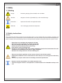
1. Safety
1.1 Marking
Danger
-
threatening danger, grievous bodily harm and death
Attention
-
dangerous situation, light bodily injury and material damage
Information
-
important information and application notice
ESD note
-
risk of damaging electronical components
1.2 Safety instructions
General
These operating instructions contain basic information which is to be complied with for installation, operation and
maintenance. They must therefore be read and complied with by the fitter and the responsible trained staff/operators
before assembly and commissioning. They must be permanently available at the place where the system is used.
-
Works have to be carried out by competent staff only
Observance of the regulations for accident prevention
Stay out of danger when lifting and setting off the unit
Secure the unit to avoid the risk of overturning
Safety devices may not be bypassed.
Respect the corresponding VDE-, EN- and IEC standards for the electrical connection of the unit
and observe the conditions of the power supply companies
- Switch off the voltage from the unit when working on it.
- Observe the national regulations of the country where the unit will be installed
- Cooling water additives have an acidic effect on skin and eyes, wear safety glasses and safety
gloves
- The unit may only be used to cool air according to the Stulz specification.
- Respect material compatibility in the whole hydraulic circuit.
- The male triangular wrench is to be placed in a visible location in the immediate vicinity of the
unit.
EN/01.2010/CW/3
1.3 Safety and environmental requirements
The following requirements relate to the operation of refrigerating plants within the European Community.
- The used components must correspond to the pressure equipment guide-line EC/97/23 and EN 378 part 1-4.
- Independent of the design, the equipment and inspection before the delivery, also the operator of such plants has
duties according to EN 378 and national regulations.
This concerns the installation, the operation and the repeated inspection:
- Installation: according to EN 378
-
Operation:
Determination of emergency measures (accidents, malfunctions)
Creation of an abbreviated instruction and notification (template page)
a. A unit protocol must be kept.
b. To be stored in the proximity of the unit
c. Access for competent staff in case of repairs and repeated inspection must be ensured.
-
Repeated inspection:
according to EN 378
The operator is responsible for the execution.
The operator must ensure that all maintenance, inspection and assembly work is carried out by authorised and
qualified specialist staff who have made an in-depth study of the operating instructions.
It is absolutely essential to comply with the procedure for shutting down the system described in the operating instructions. Before maintenance work, the unit must be switched off at the main switch and a warning sign displayed
to prevent unintentional switching-on.
Independent conversion and manufacture of replacement parts
The system may only be converted or modified after consultation with STULZ. Original replacement parts and replacement parts/accessories authorised by STULZ are an aid to safety.
Unacceptable operating methods
The operating safety of the system is only guaranteed when it is used as intended. The limit values stipulated in the
technical data must not be exceeded under any circumstances.
EN/01.2010/CW/4
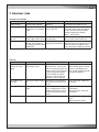
2. Residual risks
Transport, Installation
Area
Cause
Danger
Safety note
Under the unit
Defective lifting device
Bruising
Keep away from under the unit
Beside the unit
Uneven or insufficient
foundation or raised floor
stand
Bruising by tipping
over of the unit
Make sure, the foundation is even
and stable and that the raised floor
stand is correctly mounted. Wear
protective equipment (helmet,
gloves, safety shoes).
In the lower part of
the unit
Heat by soldering flame,
Burns, cuts, concussharp edges, built-in parts sion damage
Wear safety glasses and gloves,
don't put your head into the unit.
Electrical box
Electric shock, cable
Connection cable under
damage at positioning
voltage, sharp edges of
the openings for the cable
introduction
Check and make sure the unit is deenergized. Stand on isolated ground.
Take care that sharp edges are always protected by rubber grommets
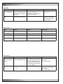
Start-up
Area
Cause
Danger
Safety note
In the lower part
of the unit, water
piping
Leaks in the water lines,
closed stop valves
Discharge of water under
high pressure, contact with
the skin of ethylen glycol, irritation of eyes and respiratory
system by glycol vapours,
increased risk of electric
shock in combination with
electricity, risk of slipping
Open stop valves.
Wear rubber gloves, ethylen
glycol is absorbed by the
skin. Avoid swallowing water
with glycol additives.
Fan outlet of upflow units
Small parts fallen into the
fan
Small parts can be thrown
out of the fan when the unit
starts.
Keep away from above the
fan outlet.
Fan, V-belt drive
Unit operation with open
doors.
Risk of injury by rotating
parts. Hanging parts of the
clothing or long hair can be
wound around the rotating
shaft.
Keep the distance to fan and
V-belt drive.
Tie up long hair, wear hair
protection.
Electrical box
Short circuit
Electric arc, acid vapours
Retighten terminal connections,
Wear protective gloves
EN/01.2010/CW/5
Operation
Area
Cause
Danger
Safety note
Unit bottom, eventually raised floor
Accumulation of condensate and water discharge
by too small or clogged
drain pipe
Corrosion and development of
mould by moistness.
Humidity in combination with
electric connections.
De-energize water discharge area.
Electrical alimentation
Falsely dimensioned cables or protection devices
Short-circuit, fire, acid vapours
Correctly design alimentation cables and protection elements. Wear
protective mask.
Area
Cause
Danger
Safety note
reheat behind heat
exchanger
Heat
Burns in case of contact to
the skin
Wear safety gloves. Avoid
contact to hot unit parts.
Heat exchanger
Sharp edges, fins
Injuries by cutting
Wear safety gloves.
Steam humidifier
Discharge of steam
Burns
Avoid area around the steam
lance.
Electrical box
Live components, supposed to be voltage-free.
Electric shock
Secure master switch against
being switched on again.
Area
Cause
Danger
Safety note
In the lower part
of the unit, water
piping
Discharge of water under
Drain of cooling water by
Unscrewing the water
drain valve.
pipes still under pressure. high pressure, contact with
the skin of ethylen glycol, in- Wear rubber gloves.
creased risk of electric shock
in combination with electricity, risk of slipping
Electrical box
Live electrical alimentation cable
Maintenance
Dismantling
EN/01.2010/CW/6
Electric shock
Check de-energized state
of the alimentation before
dismantling,
Wear safety gloves.
3. Transport / Storage
3.1 Delivery of units
Stulz A/C units are mounted on pallets and packed several times in plastic film. They must always be transported
upright on the pallets.
Construction of protective covering
(from inside to outside)
1.
2.
3.
Neopolene cushioning
Shrink film
Additional board in container shipments
The following information can be found on the packing.
1) Stulz logo
2) Stulz order number
3) Type of unit
4) Packing piece - contents
5) Warning symbols
also upon request
6) Gross weight
7) Net weight
8) Dimensions
9) Customer order number
10) Additional customer requirements
When delivery is accepted, the unit is to be checked against the delivery note for completeness
and checked for external damage which is to be recorded on the consignment note in the presence
of the freight forwarder.
•
•
•
The delivery note can be found on the A/C unit when delivered.
The shipment is made ex works, in case of shipment damages, please assert your claim towards
the carrier.
Hidden damage is to be reported in writing within 6 days of delivery.
3.2 Transport
The Stulz A/C units can be moved by lifting devices with ropes, for this the ropes have to be fixed at the pallet, and
the upper unit edges have to be protected by wooden laths or metal brackets in such a way that they could not be
caved in.
You can move the unit still packaged on the pallet with a fork lift, if you take care that the centre of gravity is within
the fork surface. Take care that the unit is in an upright position at the transport.
Never move the unit on rollers and never transport it without pallet on a fork lift, for the risk of
distorting the frame.
3.3 Storage
If you put the unit into intermediate storage before the installation, the following measures have to be carried out to
protect the unit from damage and corrosion:
• Make sure that the water connections are provided with protective hoods. If the intermediate storage exceeds 2
months, we recommend filling the pipes with nitrogen.
• the temperature at the storage point should not be higher than 42°C, and the site should not be exposed to direct
sunlight.
• the unit should be stored packaged to avoid the risk of corrosion especially of the condenser fins.
EN/01.2010/CW/7
4. Description
4.1 Type code
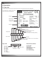
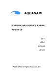
The type code represents the unit variant of your A/C unit and can be found on the rating plate.
The rating plate is located in the door in
front of the electrical compartment.
ASD 800 CW
Unit type
internal part no.
A99648
Water/Glycol
Order number
+ alternative
16
--Serial no.
Product range
Energy index
Airflow direction
Output of unit in kW
Number of refrigeration circuits
Cooling system:
CW: chilled water cooling (directly)
Explanation
A
Unit variants
Page code
Page code:
DE - German
EN - English
FR - French
ES - Spanish
PL - Polish
IT - Italian
PT - Portuguese
EN /08.2011/18/8
S
D
80
0 CW
CW, CW2
0
32, 42, 55, 65, 80, 95, 100, 118, 125, 155, 180, 210
D, U - Downflow, Upflow
S - Standard
A = CyberAir
EN / 08.2011 / 18 / 7
Page number
Date of issue Index
month/year number
Manufacturer address:
STULZ GmbH
Klimatechnik
Holsteiner Chaussee 283
22457 Hamburg
Tel: +49 40 55 85-0
Fax: +49 40 55 85-404
4.2 Intended use
This A/C unit is used to control room temperature and air humidity. The A/C unit is designed for indoor installation. Any use beyond this is not deemed to be use as intended. STULZ is not liable for any damage
resulting from such misuse. The operator alone bears the risk.
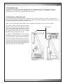
4.3 Function of the A/C unit
The A/C unit is exclusively operated by the controller in the front panel and the main switch in the electric box.
To adapt the airflow to the needs of the system the fan speed can be adjusted gradually at the controller by means
of a 0-10V signal. Minimum speed corresponds to 4V.
At the air inlet a temperature and hunidity sensor is installed. The setpoints can be set at the controller.
To control the supply air temperature the controller
adjusts the 3 way valve, which is part of the chilled
water circuit and controls the amount of chilled
water which flows through the chilled water coil.
For optional heating two variants are available:
electrical heating and hot water reheat
Electrical box
To achieve a dehumidification, the fan speed is
reduced (dehumidifying circuit). A humidification
can be obtained by using the optional humidifier.
The A/C unit control is effected by the on board I/O
controller. The operational conception is designed
such as to allow to control up to 19 units from one
unit. These units can be installed separately with a
maximum control line length of 1000 m.
Downflow unit
Upflow unit
EN /08.2011/18/9
5. Technical data
5.1 Application limits
The STULZ CyberAir 3 CW units are provided for operation within the following ranges:
- Admissible return air conditions:
Temperature:
Lower limit:
18°C
Upper limit:
35°C
Humidity:
Lower limit:
Upper limit:
5,5°C dew point
60% r.h. and 15°C dew point
- Chilled water conditions:
min. temperature at the unit inlet: 5°C
min temp. difference with 5°C EWT: 5 K
max. head pressure: 16 bar
- Storage conditions:
Temperature [°C]:
-20 - +42
Humidity [% rel. h.]:
5 - 95
Atmosphere pressure [kPa]: 70 - 110
- Voltage: Standard
380V / 3ph / 50Hz; N; PE
400V / 3ph / 50Hz; N; PE
415V / 3ph / 50Hz; N; PE
380V / 3ph / 60Hz; N; PE
460V / 3ph / 60Hz; PE
- Voltage tolerance: +/- 10%
- Frequency: 50 Hz +/- 1%
60 Hz +/- 1%
- Hot water conditions for optional heating coil:
max. inlet water temperature: 110°C
max. water head pressure: 8.5 bar
The warranty is invalidated for any possible damage or
malfunction that may occur during or in consequence of
operation outside the application ranges.
Design conditions for technical data:
Electrical connection:
for Downflow units with an external static pressure:
for Upflow units with an external static pressure:
400V/3ph/50Hz
20 Pa
50 Pa
CW Units
Return air conditions for cooling capacity:
EWT - Entering water temperature:
LWT - Leaving water temperature:
Cooling fluid:
24°C, 50% rel. humidity
7°C
12°C
Water, 0% Glycol
The sound pressure levels are valid at a height of 1m and distance of 2m in front of the unit under free field conditions
and with nominal data. The values take into account the effects of all installation and design parts contained in the
standard unit. The values for upflow units assume an installed discharge duct.
EN /08.2011/18/10
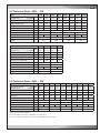
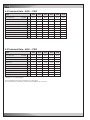
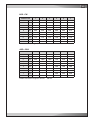
5.2 Technical Data - ASD ... CW
Modell
Type
320
420
550
650
800
950
1000
1180
kW
30,1
26,7
38,2
34,0
54,0
42,9
67,5
54,5
83,7
66,6
100,4
79,7
112,6
85,5
125,9
96,3
m³/h
7000
9000
10000
13000
15500
18500
19000
21500
G4
G4
G4
G4
G4
G4
G4
G4
m³/h
5,2
7,2
9,3
11,7
14,5
17,4
19,5
21,8
Druckverlust,
Pressure loss,wasserseitig
water side
kPa
34
53
55
85
42
61
58
72
CW -valve
Ventilgröße
(3-Wege)
size (3-way)
inch
Zoll
1 1/4"
1 1/2"
Wasserinhalt
Content of water
dm³
20,1
30,7
Schalldruckpegel
Sound
pressure level
dBA
CW-cooling capacity
CW-Kälteleistung
24°C/50% r.H.
r.F.
total
sensible
sens.
Luftvolumenstrom
Airflow
Rückluftfilterklasse
Return air filter class
Wasservolumenstrom
Water flow
Baugröße
Cabinet size
1
50,4
57,1
kg
Type
Modell
58,8
60,4
3
4
503
586
1550
1800
2100
kW
184,0
144,2
214,0
168,8
m³/h
24000
29000
33000
39000
G4
G4
G4
G4
Water
Wasservolumenstrom
flow
m³/h
23,4
27,5
31,8
37,0
Druckverlust,
Pressure
loss,wasserseitig
water side
kPa
74
105
67
91
- Ventilgröße
(3-Wege)
CW valve
size (3-way)
inch
Zoll
Wasserinhalt
Content
of water
dm³
Schalldruckpegel
Sound
pressure level
dBA
Rückluftfilterklasse
Return
air filter class
Baugröße
Cabinet
size
1
2"
Gewicht
Weight
2 1/2"
84,0
59,4
1
kg
63,9
2
159,4
126,1
Luftvolumenstrom
Airflow
60,8
350
1250
total
sensible
sens.
65,0
1
135,2
105,1
CW-cooling
CW-Kälteleistung
capacity
24°C/50% r.H.
r.F.
60,6
72,4
281
1
Gewicht
Weight
53,4
2"
108,5
64,3
61,4
65,5
5
7
688
870
5.3 Technical Data - ASU ... CW
Type
Modell
CW-cooling
CW-Kälteleistung
capacity
24°C/50% r.H.
r.F.
total
sensibel
sensible
Luftvolumenstrom
Airflow
320
420
550
650
800
950
1000
1180
1250
1550
kW
30,1
26,7
38,2
34,0
54,0
42,9
67,5
54,5
77,7
64,9
92,9
77,2
100,3
80,2
115,9
92,7
127,7
102,3
153,9
123,2
m³/h
7000
9000
G4
G4
G4
G4
G4
G4
G4
G4
G4
G4
Rückluftfilterklasse
Return
air filter class
Water
Wasservolumenstrom
flow
m³/h
5,2
6,6
9,3
11,7
13,4
16,1
17,3
20,0
22,1
26,6
Druckverlust,
Pressure
loss,wasserseitig
water side
kPa
33
52
55
85
32
45
54
71
68
97
- Ventilgröße
(3-Wege)
CW valve
size (3-way)
inch
Zoll
1 1/4"
1 1/2"
2"
2"
2"
Wasserinhalt
Content
of water
dm³
20,1
30,7
60,0
73,6
85,2
Schalldruckpegel
Sound
pressure level
dBA
Baugröße
Cabinet
size
1
1
Gewicht(standard)
Weight
1
10000 13000 16000 19000 19000 22000 24000 29000
kg
52,8
59,1
55,4
62,2
55,1
58,9
55,6
58,8
61,2
65,9
1
2
3
4
5
282
351
514
605
721
Dimensions, see following pages.
For electrical data, (fan power consumption) see e-data sheet.
The electrical power consumption of the fans must be added to the room load.
EN /08.2011/18/11
5.4 Technical Data - ASD ... CW2
Modell
Type
CW-Kälteleistung
CW-cooling capacity
24°C/50% r.F.
r.H.
total
sensibel
sensible
Luftvolumenstrom
Airflow
270
510
670
810
1070
1170
kW
31,3
28,3
49,3
42,6
68,2
60,7
86,3
74,7
107,6
93,4
137,2
120,7
m³/h
8500
11500
17500
21000
26000
36000
Rückluftfilterklasse
Return air filter class
G4
G4
G4
G4
G4
G4
Wasservolumenstrom
Water flow
m³/h
5,4
8,5
11,8
14,9
18,6
23,7
Druckverlust,
Pressure loss,wasserseitig
water side
kPa
109
79
69
91
111
85
CW -valve
Ventilgröße
(3-Wege)
size (3-way)
inch
Zoll
1
1 1/4
1 1/2
2
2
2
Wasserinhalt
Content of water
dm³
11,7
28,7
36,6
47,4
56,3
71,6
Schalldruckpegel
Sound pressure level
dBA
55,0
56,7
57,2
57,5
57,7
59,0
1
2
3
4
5
7
293
380
461
553
644
844
270
510
670
810
1070
kW
31,3
28,3
46,1
39,7
66,3
59,1
83,3
71,9
107,6
93,4
m³/h
8500
10500
17000
20000
26000
G4
G4
G4
G4
G4
1 1
Baugröße
Cabinet size
Gewicht
Weight
kg
5.5 Technical Data - ASU ... CW2
Modell
Type
CW-Kälteleistung
CW-cooling capacity
24°C/50% r.F.
r.H.
total
sensibel
sensible
Luftvolumenstrom
Airflow
Rückluftfilterklasse
Return air filter class
Wasservolumenstrom
Water flow
m³/h
5,4
8,0
11,5
14,4
18,6
Druckverlust,
Pressure loss,wasserseitig
water side
kPa
106
73
65
83
120
CW -valve
Ventilgröße
(3-Wege)
size (3-way)
inch
Zoll
1
1 1/4
1 1/2
2
2
Wasserinhalt
Content of water
dm³
11,7
28,7
36,6
47,4
56,3
Schalldruckpegel
Sound pressure level
dBA
57,2
57,4
58,9
58,8
58,9
1
2
3
4
5
296
384
476
573
718
Baugröße
Cabinet size
1
1
Gewicht
Weight
1
kg
Dimensions, see following pages.
For electrical data, (fan power consumption) see e-data sheet.
The electrical power consumption of the fans must be added to the room load.
EN /08.2011/18/12
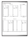
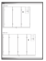
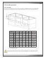
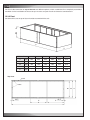
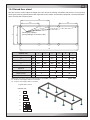
5.6 Dimensional drawings
35
Cabinet size 2
Side view
(for all sizes)
1980
10
Cabinet size 1
950
890/980*
1400
* for cabinet size 7
Cabinet size 3
Cabinet size 4
1750
2200
EN /08.2011/18/13
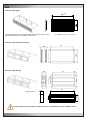
Cabinet size 5
2550
Cabinet size 7
3110
EN /08.2011/18/14
6. Installation
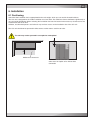
6.1 Positioning
Check that the installation site is appropriated for the unit weight, which you can read in the technical data.
The A/C unit is designed for the inside installation on a level base. The solid base frame contributes significantly to
an even weight distribution. When selecting the installation site take into account the necessary clearances for the
maintenance and the air flow.
Children, unauthorized persons and animals may not have access to the installation site of the A/C unit.
The A/C unit should not be operated in office rooms or other rooms sensitive to noise.
1m
0,5m
The unit may not be operated in an explosive atmosphere!
Maintenance clearance
Air intake area for Downflow units and air
outlet area for Upflow units without duct
connection
EN /08.2011/18/15
6.2 Water piping connection
External water circuit
To seal the water circuit you must connect the unit to a chilled water ring mains, which contains for the generation
of cold water either a chiller or a dry cooler or cooling tower. If the water quality is insufficient, we recommend the
additional installation of a fine mesh strainer.
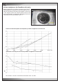
For an efficient protection against corrosion, the anti-freezing agent is mostly sufficient, which should be used if
the water temperature passes under 5°C or if the outside temperature is less than 0°C. We recommend to add the
following quantities of ethylenglycol (indicated as percentage of weight of the water quantity) :
water or outside air temperature
ethylenglycol
from +5 to -5°C
from -5 to -10°C
from -10 to -15°C
from -15 to -20°C
from -20 to -25°C
10%
20%
28%
35%
40%
correction coefficient for the pressure
drop in the water circuit when using
ethylenglycol
1.50
1.45
1.40
1.35
1.30
1.25
50%
1.20
40%
1.15
30%
1.10
20%
1.05
10%
-10
-8
-6
-4
-2
0
2
4
6
8
average chilled water temperature (°C)
For connecting the unit to the external system remove the protective caps or sealing
disks of the screwed connections.
Water remaining from the test run may escape when the protective
caps are removed.
The water connections end with an external thread. Screw the lines of the external
system to the lines of the unit respecting the designation at the unit.
Insulate the water pipes with the diffusion tight insulating material, to prevent the
introduction of ambient air heat and the formation of condensate at the pipes.
Fill and bleed air from the cooling water circuit by means of the filling connections
and the schrader valves for bleeding (see refrigerant diagram).
EN /08.2011/18/16
Connection with external
thread
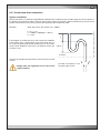
6.2.1 Condensate drain connection
Syphon installation
Ensure that there is a sufficient height difference between the condensate pan and the upper bow of the syphon or
the highest part of the drain tube, in order to avoid a water column in the drain syphon caused by the pressure in the
suction area of the A/C unit, which prevents the draining of the condensate water
Example:
Static pressure in the suction area : -300Pa
h = p / (ρ • g)
h = -300Pa / (1000kg/m³ • 10m/s²)
h = -3 cm
h
If the height h is smaller than 3 cm with a pressure of 300 Pa
in the suction area, a water column rests in the drain, the water is not transported and fills the condensate pan. This water
can be drawn dropwise in the fan or can drop out of the unit
if the pan is full.
>10 cm
unit limit
Connect the condensate water drains to the local waste water
system.
Comply with the regulations of the local water
supply authority.
possible installation at the
customer side: funnel
EN /08.2011/18/17
D
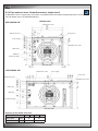
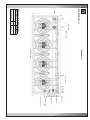
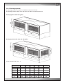
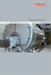
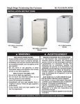
6.2.2 Pipe entrance area - Downflow version, single circuit
At Downflow units the supply pipes and cables are introduced from the bottom through openings in the base plate.
The unit bottom views are displayed following.
Bottom view
ASD 320/420 CW
Chilled water outlet
Chilled water inlet
Control lines
Power supply
Humidifier inlet/ outlet
HWR outlet
HWR inlet
Condensate drain
unit rear side
ASD 550/650 CW
Chilled water outlet
Power supply
Control lines
Chilled water inlet
Humidifier inlet/ outlet
HWR outlet
HWR inlet
Condensate drain
unit rear side
Diameter of the chilled water lines
ASD...CW
320
420
550
650
bauseits
Ø by
client
mm
35
42
external
Außengewinde
thread
inch
Zoll
R 1 1/4
R 1 1/2
EN /08.2011/18/18
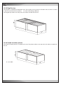
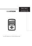
D
Bottom view
ASD 800/950 CW
Water inlet
Power supply
Water outlet
Control lines
HWR inlet
Humidifier inlet/
outlet
HWR outlet
Condensate drain
Unit rear side
ASD 1000/1180 CW
Water inlet
Power supply
Water outlet
Control
lines
HWR
inlet
Humidifier inlet/
outlet
HWR
outlet
Condensate drain
Unit rear side
HWR: Hot water reheat
Diameter of the chilled water lines
ASD...CW
800
950
1000 1180
bauseits
Ø by
client
mm
54
64
external
Außengewinde
thread
inch
Zoll
R2
R2
EN /08.2011/18/19
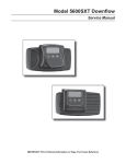
ASD 1250/1550 CW
Water inlet
Diameter of the chilled water lines
mm
R2
64
1250 1550
bauseits
Ø by
client
inch
Zoll
ASD...CW
external
Außengewinde
thread
Water outlet
Bottom view
Unit rear side
Power supply
Control lines
HWR inlet
Humidifier
inlet/ outlet
HWR outlet
Condensate drain
EN /08.2011/18/20
D
Water inlet
Water outlet
bauseits
Ø by
client
inch
Zoll
mm
R 2 1/2
64
1800 2100
external
Außengewinde
thread
ASD...CW
Diameter of the chilled water lines
ASD 1800/2100 CW
D
Bottom view
Unit rear side
Power supply
Control lines
HWR inlet
HWR outlet
Humidifier inlet/
outlet
Condensate drain
EN /08.2011/18/21
U
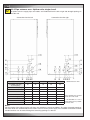
6.2.3 Pipe entrance area - Upflow units, single circuit
At Upflow units the supply pipes and cables are introduced from the left or right side through openings in
the side wall.
Connection from the left
Connection from the right
ASU ... CW
320/420
550/650
800/950
1000/1180 1250/1550
Ø
Ø Kaltwasserleitung,
Chilled water line,
by client [mm]
bauseits
35
42
54
64
64
external
thread [inch]
Außengewinde
[Zoll]
1 1/4"
1 1/2"
2"
2"
2"
Wassereintritt
Water inlet
L4
L4
L10
L10
L10
Wasseraustritt
Water outlet
L1
L1
L9
L9
L9
Kondensatablauf
Condensate
drain
L8
L8
R4
R4
R4
Power supply
Elektro-Einspeisung
R2
R2
R2
R2
R2
PWW-Eintritt
HWR inlet
R4
R4
-*
-*
-*
PWW-Austritt
HWR outlet
R5
R5
-*
-*
-*
Humidifier
Befeuchterzu-/ablauf
inlet/outlet
R8
R8
R8
R8
R8
All dimensions in mm.
The openings R1, R9 and
R10 can not be used.
* the installation of a hot
water reheat is not possible
in these units.
Notes:
For the routing of the piping into the unit there are sometimes several possibilities. The most favourable openings
are those which are recommended in the tables. The lines for the power supply, the humidifier connections and the
condensate drain can be routed through the remaining openings as desired.
EN /08.2011/18/22
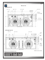
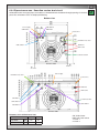
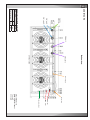
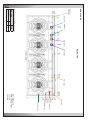
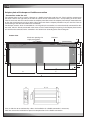
6.2.4 Pipe entrance area - Downflow version, dual circuit
At Downflow units the supply pipes and cables are introduced from the bottom through openings in the base
plate. The unit bottom views are displayed following.
D
Bottom view
CW outlet 2
Power supply
CW inlet 2
CW inlet 1
Control lines
Humidifier inlet/ outlet
CW outlet 1
HWR inlet
HWR outlet
Condensate drain
unit rear side
Power supply
Humidifier inlet/ outlet
Control lines
HWR inlet
HWR outlet
CW inlet 1
Condensate drain
CW outlet 1
CW outlet 2
CW inlet 2
unit rear side
Diameter of the chilled water lines
ASD...CW2
270
510
Ø bauseits
by client
mm
35
42
Außengewinde
external
thread
Zoll
inch
R 1 1/4
R 1 1/2
CW: chilled water
HWR: hot water reheat
1: circuit 1
2: circuit 2
EN /08.2011/18/23
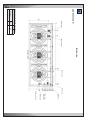
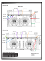
ASD 670 CW2
Bottom view
CW outlet 2
Power supply
Control lines
HWR inlet
Humidifier
inlet/ outlet
CW inlet 1
CW outlet 1
HWR outlet
CW inlet 2
Condensate drain
unit rear side
ASD 810 CW2
CW inlet 2
CW outlet 2
Power supply
Humidifier
inlet/ outlet
Control lines
CW inlet 1
CW outlet 1
unit rear side
HWR inlet
HWR outlet
Condensate drain
Diameter of the chilled water lines
ASD...CW2
670
810
bauseits
Ø by
client
mm
42
54
Außengewinde
external
thread
Zoll
inch
R 1 1/2
R2
EN /08.2011/18/24
CW: chilled water
HWR: hot water reheat
1: circuit 1
2: circuit 2
ASD 1070 CW2
Humidifier
inlet/ outlet
CW inlet 1
CW outlet 1
Diameter of the chilled water lines
mm
R2
64
1070
Ø by
client
bauseits
inch
Zoll
ASD...CW2
external
thread
Außengewinde
CW inlet 2
Bottom view
CW outlet 2
unit rear side
Power supply
Control lines
HWR outlet
HWR inlet
Condensate drain
CW: chilled water
HWR: hot water reheat
1: circuit 1
2: circuit 2
EN /08.2011/18/25
ASD 1170 CW2
Humidifier
inlet/ outlet
CW outlet 1 CW inlet 1
Diameter of the chilled water lines
mm
R2
64
1170
bauseits
Ø by
client
Zoll
inch
ASD...CW2
Außengewinde
external
thread
CW inlet 2
Bottom view
CW outlet 2
unit rear side
Power supply
Control lines
HWR inlet
HWR outlet
Condensate drain
CW: chilled water
HWR: hot water reheat
1: circuit 1
2: circuit 2
EN /08.2011/18/26
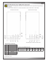
U
6.2.5 Pipe entrance area - Upflow units, dual circuit
At Upflow units the supply pipes and cables are introduced from the left or right side through openings in
the side wall.
In units of version CW2 there are 4 water connections in total (2x water inlet, 2x water outlet).
Connection from the left
Connection from the right
The openings R1 and R5 can not be used.
Designated use of openings
L1
Wassereintritt
Water inlet, circuit
Kreis 22
L2
Water outlet, circuit
Wasseraustritt
Kreis 2
L3
Wassereintritt
Kreis 11
Water inlet, circuit
L4
Wasseraustritt
Kreis 1
Water outlet, circuit
ASU ...
... CW2
CW2
ASU
270
510
670
810
1070
1170
L6
Condensate
drain
Kondensatablauf
R2
Humidifier inlet/outlet
Befeuchterzu-/ablauf
Chilled water line,
ØØKaltwasserleitung,
by client [mm]
[mm]
bauseits
35
42
42
54
64
64
R4
PWW-Eintritt
HWR inlet
R6
PWW-Austritt
HWR outlet
R8
Power supply
Elektro-Einspeisung
Diameter of the chilled water lines
All dimensions in mm.
EN /08.2011/18/27
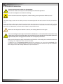
6.3 Electrical connection
Ensure that the electric cables are de-energized.
The electric cables are only to be connected by an authorised specialist.
The unit must dipose of an effective earthing.
Do not touch electronical components, without taking care of protective ESD measures.
The power supply system on site and the pre-fuses must be designed for the total current of the unit (see technical
data).
Route the electric cable into the electrics box from below and connect the hree phases to the main switch, the PE
conductor at the PE rail and the neutral conductor at the neutral terminal, in accordance with the wiring diagram
(part of the unit documents) and secure these cables by the pull relief screw.
Make sure that the phase rotation is correct, the rotating field must turn right !
For use of leakage-current (FI) circuit breakers, EN 50178 5.2.11.2 must be taken into account. Only
type B pulse-current FI circuit breakers are permitted. FI circuit breakers do not provide protection
against bodily harm during operation of the unit or frequency converters.
Make sure that the power supply corresponds to the indications on the rating plate and that the tolerances
according to the "Application limits" are not exceeded.
In addition to this, the asymmetry of phase between the conductors may amount to 2% maximally. The
asymmetry of phase is determined by measuring the voltage difference between the phase conductors.
The average value of the voltage differences may not exceed 8 V.
EN /08.2011/18/28
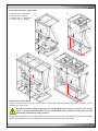
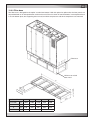
Insertion of the power supply cable
1. cabinet size 1 - Downflow
2. cabinet size 1 - Upflow
3. cabinet size 2-7 - Downflow
4. cabinet size 2-5 - Upflow
3.
1.
2.
4.
System with external pump
Choose a power switch and a contactor in respect of the pump capacity. A power switch and a contactor can be
located in the electric box.
Caution! The power supply of the pump can not be obtained via the master switch as the master
switch is designed according to the current consumption of the standard unit. The pump must be
individually provided with safety elements.
Design the wiring between the controller and the contactor with reference to the connection diagram for the controller
and the wiring between the pump and power switch according to the manufacturer's notes.
EN /08.2011/18/29
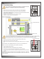
7. Commissioning
The unit must be installed and connected in accordance with the
chapter on "installation" before initial commissioning.
•
•
•
•
•
Make sure that the master switch is off and the unit is de-energized.
Open the electrical compartment door of the unit using the key provided.
Check whether all power switches and control-circuit fuses in the electrical section
of the unit are switched off.
Retighten all screw connections in the electric cabinet.
Verify the smooth function of the contactors.
Power switch off
Electrical compartment
Power switches
Control-circuit fuses
Master switch
Do not turn the adjustment screw beyond the end of the calibrated scale range, as it may result in
overheating and short-circuit at the consumer or in the destruction of the power switch.
•
•
•
Adjustment of the power switches according to electrical data sheet.
Switch on the A/C unit at the master switch.
Switch on the control-circuit fuses and the power switch of the fan in sequence.
The controller is now supplied with power, so you can use it for adjustments.
non-calibrated range
Make sure that the heat rejecting system (chiller) is operating.
•
•
Close all doors of the A/C unit.
Adjust the desired return air temperature at the controller.
•
•
Start the A/C unit by pressing the Start/Stop-key on the controller.
Instruct the operational staff of the controller manipulation (refer to the controller
manual).
The doors can only be opened with the key provided and represent a protective
device. During operation the doors may not be opened and the rear panels may
not be removed.
EN /08.2011/18/30
Switching on power switch
8. Maintenance
8.1 Safety instructions
All maintenance work is to be carried out under strict compliance with the country-specific accident prevention regulations. In particular we refer to the accident prevention regulations for electrical installations, refrigerating machines
and equipment. Non-compliance with the safety instructions can endanger people and the environment.
Maintenance work is only to be carried out on the units by authorized and qualified specialist staff.
Procedure instructions
Work on the system must always only be carried out when it is shut down. To do this, the unit must be
switched off at the controller and at the master switch. A „DO NOT SWITCH ON“ warning sign must be
displayed.
Live electrical components are to be switched to de-energized and checked to ensure that they are in the
de-energized state.
Some verifications must be effected with the unit in operation (measuring the current, pressures, temperatures). In such a case the unit must only be switched on at the master switch after all mechanical connections
have been carried out. The unit must be switched off immediately after the measuring procedure.
Warning notes!
When the master switch is switched on and the controller is stopped the power contactors are live,
even if the components are not operating.
At the fan contactor, dangerous voltages occur. Do not open the unit within the first 5 minutes after
disconnection of all phases. Be sure that the unit is being isolated.
In units with 2 or 3 fans dangerous charges of >50µC can occur between AC line terminals and PE
after disconnection.
The electronics housing can get hot.
The fans have an operation delay after the unit is stopped ! (Risk of injury)
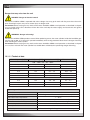
8.2 Maintenance intervals
Component
Maintenance interval
monthly
Air circuit
Heat exchanger
Fan
Air filter
Water circuit
Tightness
Unit in general
Electrics
Mechanics
quarterly
half-yearly
yearly
x
x
x
x
x
x
EN /08.2011/CW/31
8.3 Air circuit
Heat exchanger (CW-coil)
The heat exchanger consists of copper tubes with aluminium fins. If refrigerant leaks occur, they should be searched
for at the heat exchanger. Beyond that, the heat exchanger is exposed to the air pollution, the particles of which
settle at the fins and reduce the heat transmission the same as raise the air resistance. The latter shows when the
fan current increases.
The heat exchanger can be cleaned by pressurized air which has to be blown opposite to the normal air flow direction
along the fins.
Do not distort the fins while cleaning, this also increases the air resistance !
Fan
The bearings of the fans are lifetime lubricated and do not need maintenance. Check the operation current. An increased operation current indicates either a higher air resistance by a clogged pre-filter or a winding short circuit in
the fan motor.
The fans are speed controlled in dependance of the required cooling capacity. You can manually modify the speed
at the controller for test purposes, so as to compare the measured current with the values on the pages with the
technical data or with those of the planning tool.
Air filter
A filter monitor controls the state of the filter. As soon as the pressure loss exceeds an adjustable value, a filter alarm
via the controller is released. The controller can be configured such as to compensate the pressure loss by a higher
fan speed, however you should not wait too long for exchanging the filter. The filters can be accessed by the front
doors, depending on the cabinet size the number of filter elements varies.
The clogged filter elements can not be cleaned with pressurized air, as the filter structure would be destroyed otherwise. When you re-install the filter elements after the exchange, take care that the side with the coloured mark (dirt
side) is turned away from the heat exchanger.
8.4 Water circuit
Tightness
Check the water circuit visually for tightness. Beyond that a level indication at the storage tank, if existant, can give
information about changes of the water quantity. A lack of water in the circuit is replaced by air, which reduces the
heat capacity of the chilled water circuit and is detrimental to the pump.
8.5 Unit in general
Electrics
Check the connection terminals for tight fixation when the unit is installed and once again after an operation time of
30 days.
Mechanics
Clean the unit's inside with a vacuum cleaner. Clean pipes simplify the search for leaks. Check the pipes for a tight
seat. Vibrations of pipes and circuit components can result in leaks. Check also the insulation of the water piping.
Condensing air humidity on cold water pipes means a loss of cooling capacity.
EN /08.2011/CW/32
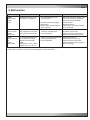
9. Malfunction
Alarm message Cause for alarm
Cause
Elimination
1. Fan motor defective. Fan
speed too low.
Check fan motor on voltage continuity and current consumption.
Fan mechanically blocked?
Check air filter.
Exchange V-belt.
Clean hoses and check whether
they are kinked .
C7000:
Airflow failure
C1002:
FLO#
Differential pressure for airflow switch has triggered.
C7000:
Sensor # error
C1002:
not existant
The tolerance to the average 1. Big difference of measeured
value adjustable in the contvalues in selected zone.
roller has been exceeded.
2. sensor defective.
C7000:
Sensor # defective
C1002:
SE t or SE h
The measured voltage/current is outside the range
defined in the controller.
C1002:
temperature: <3°C or >50°C
humidity: <3% or >97% r.h.
2. Air filter extremely clogged.
3. V-belt worn.
4. Hoses to the airflow monitor
dirty or kinked.
Check room on Hotspots or chilled
air zones, moist zones.
Check measured value with an
external measuring instrument.
1. electrical connection defective. Check connections.
2. sensor cable defective.
Check cable on continuity.
3. sensor defective.
Check measured value with
external thermometer, hygrostat,
pressure gauge.
Depending on the option configured in the controller further alarm messages exist.
# stands for a number in case of several components of the same kind.
EN /08.2011/CW/33
10. Dismantling and disposal
The A/C unit can only be dismantled by qualified specialists.
Switch off the A/C unit at the controller and at the master switch. Switch off power conducting cables to the unit and
secure them against being switched on again. Disconnect the A/C unit from the de-energized network.
If glycol or similar additives had been used, this liquid has to be collected and disposed in an appropriate manner and may under no circumstances be introduced in the local waste water system.
Disconnect the unit from the external water circuit by closing the shut-off valves and drain the water circuit of the
unit.
Disconnect the depressurized cooling water pipes of the unit from the external system.
Move the unit, as described in the chapter "transport", with a lifting device of sufficient load-carrying capacity.
Dispose of the A/C unit in accordance with the disposal and safety regulations applicable on site. We recommend a
recycling company for this. The unit basically contains the raw materials aluminium (heat exchanger), copper (pipelines, wiring), and iron (panelling, mounting panel).
EN /08.2011/CW/34
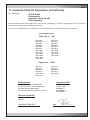
11. Contents of the CE Declaration of Conformity
The undersigned
STULZ GmbH
Klimatechnik
Holsteiner Chaussee 283
22457 Hamburg
hereby confirms that the units listed below, in the version marketed by us, fulfil the requirements of the harmonised
EC directives and EC safety standards listed below.
In the case of a modification of the equipment not co-ordinated with us this declaration loses its validity.
Air conditioning unit
Cyber Air 3 ... CW
ASD 320 ...
ASD 420 ...
ASD 550 ...
ASD 650 ...
ASD 800 ...
ASD 950 ...
ASD 1000 ...
ASD 1180 ...
ASD 1250 ...
ASD 1550 ...
ASD 1800 ...
ASD 2100 ...
/
/
/
/
/
/
/
/
/
/
ASU 320 ...
ASU 420 ...
ASU 550 ...
ASU 650 ...
ASU 800 ...
ASU 950 ...
ASU 1000 ...
ASU 1180 ...
ASU 1250 ...
ASU 1550 ...
Cyber Air 3 ... CW2
ASD 270 ...
ASD 510 ...
ASD 670 ...
ASD 810 ...
ASD 1070 ...
ASD 1170 ...
/
/
/
/
/
ASU 270 ...
ASU 510 ...
ASU 670 ...
ASU 810 ...
ASU 1070 ...
EC-Directives
Harmonised EN
EC machinery directive 2006/42/EC
EC directive for low voltage 2006/95/EC
EC EMC directive 2004/108/EC
EC pressure equipment directive 97/23/EC
EN ISO 12100 -1/2
EN ISO 13857
EN 60204 -1
EN 61000-6-2
EN 61000-6-4
National regulation
BGV A3
BGV D4
Hamburg, 01.09.2011
Place, date
ppa.
Works management: Mr. Panknin
EN /08.2011/CW/35
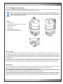
12.1 Steam humidifier
The steam humidifier is an optional extra for your A/C unit. It is installed complete and integrated within the function
and method of operation of the A/C unit. Details concerning the connection assignment for the power supply can be
found in the electrical diagrams in the appendix.
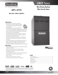
12.1.1 Description
The steam humidifier OEM2 is a pressureless steam generator that utilizes an electrode heating and is designed for
air humidification via a steam distributor (steam distribution pipe, steam nozzle).
Steam generation
Any time steam is requested, the electrodes (2) are supplied with voltage
via main contactor (1). Simultaneously, the inlet valve (7) opens and water
enters the steam cylinder (3) from the bottom via water cup (4) and supply
line (5). As soon as the electrodes come in contact with the water, current
begins to flow between the electrodes, eventually heating and evaporating
the water. The more the electrode surface is exposed to water, the higher is
the current consumption and thus the steam capacity.
Upon reaching the requested steam capacity, the inlet valve closes. If the
steam generation decreases below a certain percentage of the required
capacity, due to lowering of the water level (e.g. because of the evaporation
process or drainage), the inlet valve opens until the required capacity is
available again.
If the required steam capacity is lower than the actual output, the inlet valve
is closed until the desired capacity is achieved by lowering of the water level
(evaporation process).
Level monitoring
A sensor provided in the steam cylinder cover detects when the water level
gets too high. The moment the sensor comes in contact with water, the inlet
valve closes.
Drainage
On/Off control
Proportional control
As a result of the evaporation process, the conductivity of the water increases
due to an escalating mineral concentration. Eventually, an inadmissibly high
current consumption would take place if this concentration process were
permitted to continue. To prevent this concentration from reaching a value,
unsuitably high for the operation, a certain amount of water is periodically
drained from the cylinder and replaced by fresh water.
During the drainage process, the drain valve (6) is opened. Following a predetermined time of drainage, the drain valve is closed again.
Control
With the ECCM/S control unit either On/Off control or proportional control
can be employed for steam production.
Below a minimum controllable steam output, proportional control will work
in two-point operation (on/off control).
X = steam capacity in %
Y = Output signal controller
EN/04.2011/humidifier/1
Danger that may arise from the unit
DANGER! Danger of electric hazard!
The steam humidifier OEM2 is operated with mains voltage. One may get in touch with live parts when the unit is
open. Touching live parts may cause severe injury or danger to life.
Prevention: Before carrying out any work set the steam humidifier OEM2 out of operation as described in chapter
12.1.3.5 (switch off the unit, disconnect it from the mains and stop the water supply) and secure the unit against
inadvertent power-up.
WARNING! Danger of burning!
The steam humidifier OEM2 produces steam. When producing steam, the steam cylinder inside the humidifier gets
very hot (up to 100 °C). If the unit is opened immediately after having produced steam there is danger of burning
when touching the steam cylinder.
Prevention: Before carrying out any work set the steam humidifier OEM2 out of operation as described in chapter
12.1.3.5, then wait until the steam cylinder has cooled down sufficiently thus preventing danger of burning.
12.1.1.1 Technical data
Steam
Dampfleistung
capacity [kg/h]
[kg/h]
Nominal
Nennleistung
power[kW]
[kW]
Nominal
Nennstrom
current
[A][A]
Maximalstrom
Max. current [A]
[A]
200 ... 230V / 1N~ / 50 ... 60Hz
2,0
1,5
7,5 ... 6,5
9,4 ... 8,2
4,0
3,0
15,0 ... 13,0
18,8 ... 16,3
200 ... 230V / 3~ / 50 ... 60Hz
4,0
3,0
8,7 ... 7,5
10,8 ... 9,4
8,0
6,0
17,3 ... 15,1
21,7 ... 18,8
10,0
7,5
21,7 ... 18,8
27,1 ... 23,5
380 ... 460V / 3~ / 50 ... 60Hz
4,0
3,0
4,6 ... 3,8
5,7 ... 4,7
8,0
6,0
9,1 ... 7,5
11,4 ... 9,4
15,0
11,25
17,1 ... 14,1
21,4 ... 17,6
Operating conditions
Admissible water pressure
Water quality
Admissible water temperature
Admissible ambient temperature
Admissible ambient humidity
Adm. back pressure at steam connection
Type of protection
Conformity
EN04.2011/humidifier/2
1 ... 10 bar
Drinking water with a conductivity of 125 - 1250µS/cm
1 ... 40 °C
1 ... 50 °C (control unit 1 ... 40 °C)
max. 75% rh, non-condensing
- 0,5 kPa ... 1,0 kPa
IP00
produced according VDE regulations 0700 and 0700 part 98
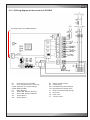
12.1.1.2 Wiring diagram of the control unit ECCM/S
input signal from the C7000 controller
to C7000
alarm input
{
Danger
Mains voltage
B5
F1
F2/Q2
F3/Q3
H1
H2
H3
JP1
JP2
Level sensor steam cylinder
Fuse control board (2 A, time-lag)
Automatic fuse control voltage
MCB humidifier
Red LED: Error
Yellow LED: Service, Warning
Green LED: Steam production
Jumper block 1
Jumper block 2
S1
S2
Sx%
%rH
Y1
Y2
Y3
T1
Rotary switch unit type
Drain/Info key
Potentiometer power limitation
Potentiometer humidity value
Main contactor heating voltage
Inlet valve
Drain valve
Current sensor
EN/04.2011/humidifier/3
12.1.1.3 Configuration of the control unit ECCM/S
Setting the capacity limitation “Sx%”
Use the potentiometer “Sx%” to set the capacity limitation in % of the maximum capacity (setting range: 25...100%,
factory setting: 100%).
Setting the control signal
With the jumpers on jumper block “JP1” you can set the control signal. The control signal is adjusted on 0-10V, none
of the jumpers "mA", "SP", "2P" on jumper block "JP1" may be set for this.
General unit settings
With the jumpers on the jumper blocks “JP1” and “JP2” you can set different unit parameters.
Pos.
with jumper
without jumper
Fi
Connection to a mains supply with ground fault
circuit interrupter **
Connection to a mains supply without ground
fault circuit interrupter
DRN
Increased drain operation factor
Regular drain operation factor **
CDY
Low water conductivity (<125 µS/cm)
Normal water conductivity (≥125 µS/cm) **
DSP
Exchangeable steam cylinder **
Cleanable steam cylinder
K
Fault No. 4 “steam cylinder maintenance due”:
the unit triggers a warning only (the error switch
on the control unit ECCM/S is not activated).
Fault No. 4 “steam cylinder maintenance due”:
72 hours after the warning an error is triggered and
the unit is switched off (red LED lights). However, the
error switch on the control unit ECCM/S is activated
already in warning status. **
L
Fault No. 3 “Fill time”: a warning is triggered after
20 minutes filling time exceeding. After 220 minutes
filling time exceeding an error is triggered and the
unit is switched off (red LED lights and the error
switch on the control unit ECCM/S is activated). **
Fault No. 3 “Fill time”: the unit directly triggers an
error after 20 minutes filling time exceeding (red
LED lights and the error switch on the control unit
ECCM/S is activated). However, the unit is switched
off after 220 minutes filling time exceeding.
Z, M, N
no function (spare)
** Factory settings
EN04.2011/humidifier/4
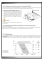
12.1.2 Supply connections
The steam humidifier is installed and electrically connected in the A/C unit. The local regulations of the water supply
company are to be complied with when making the hydraulic connection.
We recommend the installation of an Aqua-stop valve in the water supply of the humidifier. In addition to this, the room, in which the A/C unit with the humidifier is installed, should be equipped
with a water detection system.
Legend:
1 Level sensor
2 Steam outlet connector ø22.5 - 30 mm
3 Heating electrodes
4 Inlet valve
5 Outlet valve
6 Drain connector ø22.1 mm
7 Water supply connector G 3/4“
Water supply
The water connection is made from the cold water mains and is to be equipped with a shut-off valve. It is recommended to install a filter to retain solid particles of pollution. The humidifier can be connected directly to the mains
by a threaded tenon of 3/4" when the water pressure is between 1 and 10 bar. The pipe should have a diameter of
at least 6 mm. In the factory a 680 mm hose with 3/4 inch nut on each side is mounted to simplify the connection to
the piping on site.
If the line pressure is more than 10 bar, the connection must be made via a pressure reducing valve (set to 4-6 bar).
In each case it is to be ensured that the manufactured water pipe upstream of the connection to the humidifier is
flushed properly. We recommend only using copper pipes. The water supply temperature must not exceed 40°C.
Water drain
The drain connection has an outside diameter of 22.1 mm. A plastic hose can be connected to the drain connection
which can be routed out of the unit by means of the openings in the unit provided for this purpose.
When creating the drain, attention is to be paid to provision for cleaning.
As the
the water
waterdrain
drainisisdepressurized,
depressurized,wewe
recommend
routing
drain
hose
first into
an open
collector
funnel and
recommend
routing
thethe
drain
hose
passing
through
a syphon,
as described
in
then
passing
through
a syphonunder
to the"syphon
drainage
system to ensure
the unit
operating
instructions
installation",
into an free
opendischarge.
collector funnel to ensure free discharge.
The drainage pipe should be routed to the sewerage system with sufficient gradient (at least 5%) and should be located
approx. 30 cm below the humidifier. Attention is to be paid to temperature resistance when plastic pipes are used. If
copper pipe is used, it must be earthed. For the drainage pipe an inside diameter of at least 22 mm is required.
EN/04.2011/humidifier/5
12.1.3 Operation
12.1.3.1 Function of the display and operating elements on the control unit ECCM/S
1 Drain/Info key
– press key shortly: opens and closes the drain valve (manual draining).
Note: the drain valve is automatically closed after 10 minutes.
– press key for a extended period of time: activating the info mode
2 Error indication (red LED)
– in normal operating mode
The LED lights in case of a malfunction of the unit. Further operation is no longer possible, the heating
voltage is interrupted. An alarm signal is sent to the C7000 controller. At the C7000AT the alarm "HUMIDIFIER 1 FAILURE" is displayed.
– in info mode
LED blinks in intervals if a malfunction is present. The number of “blinks” per interval indicates the number
of the error (see chapter 12.1.4.3).
3 Warning and info indication (yellow LED)
– in normal operating mode
– The LED blinks, if manual draining is in progress.
– The LED lights if the cylinder maintenance is due or the maintenance indication is not reset after the maintenance.
– in info mode
LED blinks in intervals if a malfunction with status warning is present. The number of “blinks” per interval
indicates the number of the error (see chapter 12.1.4.3).
4 Steam production (green LED)
– in normal operating mode
The LED lights if the unit produces steam.
– in info mode
LED blinks in intervals. The number of “blinks” per interval multiplied by 10 indicates the current steam
output in % (see chapter 12.1.3.3).
EN04.2011/humidifier/6
12.1.3.2 Commissioning
Proceed as follows when putting the unit into operation:
1.
2.
3.
4.
Examine the steam humidifier and installation for possible damage.
Open the shut-off valve (if existant) in the water supply line.
Switch on control fuse and humidifier power switch in electric box. Switch on main switch.
Adjust the humidity set value at the C7000 controller. To force humidifer operation for a functional test you can
either increase the set value or start the humidifier by the manual operation function of the C7000.
After switching on the control unit ECCM/S carries out a system test, during which all the LEDs on the control unit
light up in sequence.
If, after the system test (or during operation) the yellow or red LED lights up, an error has occurred (see information
in chapter 12.1.4 “Fault elimination”).
After switching on the steam humidifier is ready for operation. As soon as the C7000 controller requires humidity,
power is switched on and the green LED lights on the control unit ECCM/S. The inlet valve opens after approx. 60
seconds and the steam cylinder fills with water. The submerged electrodes heat the water up and after a few minutes
(approx. 5–10 minutes, depending on the conductivity of the water) steam is produced.
Note: If the water has low conductivity, it is possible in the first few hours of operation that the maximum steam
output is not achieved. This is normal. As soon as the water reaches adequate conductivity through the vaporization
process, the steam humidifier will work at maximum output.
12.1.3.3 Function of the LEDs in info mode
The info mode is activated by pressing the drain/info key for an extended period of time (> 3 seconds). In info mode
the LED‘s on the control unit indicate the current operating status of the steam humidifier.
Note: The info mode is automatically reset after 15 minutes, or manually by pressing the drain/info key again.
– the green LED blinks. The number of blinks indicates the current steam output in % of the maximum steam capacity:
green LED blinks...
1x
2x
3x
4x
5x
6x
7x
8x
9x
10x
Steam capacity in %
10
20
30
40
50
60
70
80
90
100
12.1.3.4 Manual draining
1. Briefly press the drain/info key. The heating voltage is interrupted and the drain valve opens. The yellow LED
blinks.
Note: the drain valve closes after 10 minutes automatically
2. To stop the drain cycle briefly press the drain/info key again.
12.1.3.5 Taking the unit out of operation
1. If the unit has to be switched off because of a malfunction, please activate the info mode (see chapter 4.4.1) and
note the number (number of blinks of the red LED) of the actual error.
2. Close the shut-off valve in the water supply line.
3. Start manual draining and wait until the steam cylinder is empty (approx. 5-10 minutes).
4. Disconnect the steam humidifier from the mains: Switch off the humidifier power switch in the electric box.
EN/04.2011/humidifier/7
12.1.4 Fault elimination
Important! Most operational malfunctions are not caused by faulty equipment but rather by improper installation or
disregarding of planning guidelines. Therefore, a complete fault diagnosis always involves a thorough examination
of the entire system. Often, the steam hose connection has not been properly executed, or the fault lies with the
humidity control system.
12.1.4.1 Fault indication
LED on control unit ECCM/S
Description
yellow
red
blinks permanently
–––
lights
–––
lights
lights
Steam cylinder maintenance not executed or maintenance indication not
reset.
–––
lights
Fatal malfunction.
Drain/info key has been pressed shortly (manual draining in progress)
Steam cylinder maintenance due or maintenance indication not reset.
If the yellow or red LED lights, press drain/info key (at least 3 seconds) until yellow (“Warning”) or red (“Error”) LED
starts blinking intermittently (info mode). The amount of “blinks” per interval indicates the type of malfunction.
– Yellow LED “Warning” blinks intermittently
A malfunction is present. The control unit checks whether there is a temporary problem (e.g. water supply interrupted
for a short time) or whether it can resolve the problem by taking necessary measures.
– Red LED “Error” blinks intermittently
The control unit, after several attempts, fails to solve the problem (number of attempts depends on the type of
malfunction) or the problem obstructs further operation. In this case the heating voltage is interrupted via the main
contactor.
12.1.4.2 Notes on fault elimination
DANGER! Danger of electric hazard!
For the elimination of faults set the steam humidifier out of operation as described in chapter 12.1.3.5, separate the
unit from the mains (test with voltage tester) and secure it against inadvertent power-up.
Do not touch electronical components, without taking care of protective ESD measures.
EN04.2011/humidifier/8
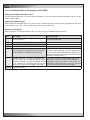
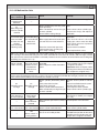
12.1.4.3 Malfunction lists
“Warning”
yellow LED blinks
“Error”
red LED blinks
1x
Control board
defective
---
2x
Max. filling level
of steam cylinder
reached
3x
Permissible filling
time exceeded
for more than 20
minutes
(first automatic
cleaning cycle)
---
Cause
Remedy
Control board defective
Please contact your unit supplier.
Water conductivity too low (after
initial operation).
Water conductivity too low for type
of steam cylinder.
Phase failure heating voltage.
Wait.
3x
Phase failure heating voltage.
Permissible filling
time exceeded for Water supply obstructed, water presmore than
sure too low, inlet valve defective.
220 minutes.
Excessive steam back pressure,
causing water loss via filling cup.
Drain valve is leaking.
Select correct steam cylinder type.
Check mains fuse(s) and replace if
applicable.
Check mains fuse(s) and replace if
applicable.
Open shut-off valve in the water
supply pipe, clean water inlet filter,
check water pressure, inspect/replace inlet valve.
Inspect steam installation.
Clean/replace drain valve.
Note: if the Jumper “L” is removed from the ECCM/S control unit, the unit automatically triggers an error without
prior warning if the admissible filling time has been exceeded for more than 20 minutes (red LED lights and the
error switch on the control unit ECCM/S is activated). However the unit switches off after 220 minutes of filling time
exceeding (see chapter 12.1.1.3).
4x
Steam cylinder
needs servicing
4x
Interval for steam
cylinder service
exceeded for
more than 72
hours
Interval for steam cylinder service
exceeded.
Mineral deposits and/or electrodes
spent.
Replace steam cylinder type A, clean
steam cylinder type D (see chapter
5, original instruction).
Important! Refer to chapter 5.6 for
resetting the maintenance indicator.
(see chapter 5.6, original instr.).
Note: if the Jumper “K” is installed on the ECCM/S control unit, the unit remains in warning status even if the interval
time has been exceeded for more than 72 hours. No error is triggered (red LED does not light) and the error switch
on the control unit ECCM/S is not activated (see chapter 12.1.1.3).
6x
Electrode current
too high
Steam cylinder (electrodes) defective.
6x
Faulty auto-drain function.
Electrode current Faulty drain valve/coil.
too high
Steam cylinder outlet obstructed.
Water conductivity too high for type
of steam cylinder.
7x
Foam detection in
the steam cylinder
7x
Foam control
impossible
---
8x
Main contactor
jammed
Formation of foam in steam cylinder. Empty/flush steam cylinder.
Set jumper on “DRN” (see chapter
12.1.1.3).
Main contactor jammed in activated Check/replace main contactor.
position.
9x
9x
Drain valve blocked or defective.
Drain valve blocked Drain valve blocked Steam cylinder outlet blocked.
---
10x
Rotary switch in
wrong position
Replace steam cylinder or electrodes.
Inspect installation/control system.
Replace drain valve/coil.
Clean/replace steam cylinder.
Select correct steam cylinder type.
Clean/replace drain valve.
Clean steam cylinder outlet.
Rotary switch on control unit ECCM/ Set rotary switch on control unit
S is set to an invalid position.
ECCM/S to the position for the corresponding steam cylinder type (see
chapter 3.4.3, original instruction).
EN/04.2011/humidifier/9
12.1.4.4 Replacement of fine-wire fuse on the control unit ECCM/S
If the fine-wire fuse on the control unit ECCM/S blows this is usually due to a faulty coil of the inlet or drain valve or
the main contactor. Therefore you should test these components before replacing the fuse.
To replace the fine-wire fuse proceed as follows:
1. Set the steam humidifier OEM2 out of operation as described in chapter 12.1.3.5, separate the unit from the
mains and secure it against unintentional switching on.
Take care that the electricity supply to the control unit
ECCM/S is disconnected (check with voltage tester).
2. Replace fine-wire fuse (see figure below) with a fuse
of the given type with the specified nominal current
rating.
2 A, time-lag
CAUTION!
It is not permitted to use repaired fuses or to short-circuit
the fuse holder.
12.1.4.5 Resetting fault indication (red LED lights in normal operating mode)
To reset the error indication:
Disconnect the steam air humidifier from the mains. Wait approx. 5 seconds, then reconnect the unit to the mains.
Note: If the fault has not been eliminated, the error indication reappears after a short while.
12.1.5 Maintenance
You find a detailed description of the maintenance procedures in chapter 5 of the original instruction. Here you can
only see a diagram, which shows the average life cycle of a steam cylinder in dependance of the runtime and the
total hardness.
The humidifier runtime can be read in the Info menu of the C7000AT or by the command "humi h" in the C7000.
Service intervals for steam cylinder
depending on steam production in hours
Life time
range
GH: Gesamthärte
DT: Dureté totale
TH: Total hardness
Time/
hours
EN04.2011/humidifier/10
12.2 Reheat
The reheat is an optional extra for your A/C unit. It is installed complete and integrated in the function and method
of operation of the A/C unit. It is used to heat up the air. The following versions of the heater are available:
- Electrical reheat
- Hot water reheat (HW)
- Hotgas reheat (HG)
Description
Electrical reheat
HW reheat
HG reheat
The HW reheat is to be connected
to an external hot water circuit.
The water supply is controlled via
an electrically actuated HW valve.
The HW valve is controlled via the
controller. The control parameters
are adjusted in the "operate/components/heating/HWR valve" menu on
the controller. Refer to the operating
instructions C7000.
C1002: menu item 12-14 (E, F, H)
C6000: Control/module functions/
Heating/HWR-valve
The hotgas reheat is integrated in
the refrigerant circuit in accordance
with the refrigerant diagram in the
appendix. The refrigerant supply is
controlled via an electrically-actuated
3-way solenoid valve. The solenoid
valve is controlled via the controller.
The control parameters are adjusted
in the "operate/components/heating"
menu on the controller. Refer to the
operating instructions C7000.
C1002: menu item 12-14 (E, F, H)
Cabinet size 1
Cabinet size 2
The reheat is connected in accordance
with the electric diagram. It is controlled and monitored by the controller.
The values for switching on and off are
adjusted in the "operate/components/
heating" menu on the controller. Refer
to the operating instructions C7000.
C1002: menu item 12-14 (E, F, H)
C6000: Control/module functions/Heating/E-heating
Operation
The reheat is controlled and monitored by the controller. No further measures are required for operation.
Maintenance
Clean the reheat annually from contaminations and check it for damage.
EN/01.2010/reheat/1
Installation
The reheats are installed and connected in the A/C unit. The HW reheat is to be connected on site to the external
hot water circuit. The pipelines are to be routed out of the A/C unit. The thread sizes for the connection piping of
the HW reheat are listed in the following table.
Temperatures:
Water inlet:
60°C
Water outlet:
40°C
Air inlet:
13°C
Glycol: 0%
Cabinet size
1
2
3
4
5
7
Pipe - Ø
mm
16
22
22
22
28
28
Thread size
inch
1/2
3/4
3/4
3/4
1
1
Commissioning
The reheats are controlled and monitored by the controller of your A/C unit. No further measures are required for
commissioning.
Malfunction causes
Alarm: Reheat defect
All reheat alarms are received by the controller and can be requested according to the equipment.
C7000-control system:
C7000 advanced terminal:
C1002:
EN/01.2010/reheat/2
no display (display only externally)
indication on the display
display: HEA
12.3 Air side connection
12.3.1 Unit base
L3
E
450
The unit base is available in the versions: open, with damper, with flexible connection or with supply grilles.
The unit base can be installed in two ways, with the opening to the front or with the opening to the rear.
L1
L4
L1
A
B
C
D
T
Cabinet
Baugröße
size
1
2
3
4
5
7
910
1360
1710
2160
2510
3070
210
182
69
173
42,5/65*
A
mm
B
mm 130/47,5*
C
mm
-
-
-
-
993
-/1027,5*
D
mm
-
-
927
1276
1738
1727,5/2190*
E
mm
75/67,5*
68
68
67,5
68
52,5/67,5*
L1
mm 700/815*
1015
615
815
615
1300/815*
L2
mm 700/800*
1000
600
800
600
1300/800*
L3
mm 300/315*
315
315
315
315
345/315*
L4
mm
-
-
-
-
615
1015*
L5
mm
-
-
-
-
600
1000
T
mm
865
865
865
865
865
955
1/1*
1/1*
2/2*
2/2*
3/3*
2/3*
N°
*version with grilles
N°: Number of openings
Caution! Each of the unit base versions must be screwed to the unit by 4x M10 screws!
EN /08.2011/air/1
Unit base with grilles
/ L5
The standard grilles are equipped with horizontal fins which can be
adjusted to conduct the air which is blown out.
L5: middle position for size 5 and 7
Unit base with flexible connection
L2
300
150
Unit base with damper
L2
38
300
120
175
L2
345
Cabinet size 7:
Caution! Each of the unit base versions must be screwed to the unit by 4x M10 screws!
EN /08.2011/air/2
12.3.2 Filter base
The filter base is designed for the option "suction from bottom". With this option for upflow units the front panels are
not provided with an air inlet perforation as otherwise usual. The air is drawn in from the bottom, in consequence there
is no unit bottom plate, but supporting bars instead, on which compressors and other components are mounted.
Filter base
Unit base or raised
floor stand
Construction
Baugrößesize
1
2
3
4
5
unit width
Gerätebreite
mm
1000
1400
1750
2150
2550
A
mm
960
1360
1710
2110
2510
B
mm
270
293
376
376
456
Filteranzahl
N° of filters
mm
3
4
5
EN /08.2011/air/3
For the air side connection on top of the unit exist different options, which are delivered in a completely assembled
condition. On the installation site these set-ups must be set upon the unit and must be connected to it.
12.3.3 Duct
500 / 800
The duct will be set on top of the unit and be screwed with the unit.
The duct is available with two different heights (500 or 800 mm) for all units.
B
A
Cabinet
Baugröße
size
1
2
3
4
5
7
A
mm
884
884
884
884
884
974
A1
mm
840
840
840
840
840
930
A2
mm
784
784
784
784
784
874
B
mm
950
1400
1750
2200
2550
3110
E
mm
-
-
-
-
-
939
Top view:
panel
E
B
E
B
EN /08.2011/air/4
E
A
A1
A2
A=
frame
12.3.4 Discharge plenum
The discharge plenum is availale in two different versions for all units.
The discharge plenum will be set on top of the unit and be screwed with the unit.
500
400
Discharge plenum with front grilles
L1
L1
D
B
C
T
400
500
400
Discharge plenum with front and side grilles
L1
D
B
L1
T1
C
T
Only one front grille for size 1, 2.
Three front grilles for size 7.
Cabinet
Baugröße
size
1
2
3
4
5
7
B
mm
950
1400
1750
2200
2550
3110
C
mm
75
100
45
112,5
100
140
D
mm
-
-
905
1287,5
1450
1770
L1
mm
800
1200
2 x 800
T
mm
884
884
884
884
884
974
T1
mm
600
600
600
600
600
800
2 x 800 2 x 1000 2 x 1200
EN /08.2011/air/5
12.3.5 Bag filter top
500
The bag filter is available for all downflow units. The bag filter serves for the pre- filtration of the air which is sucked
in and can be obtained in the qualities F6, F7 and F9 (according to EN779).
The bag filter top will be set on top of the unit and be screwed with the unit.
B
884
12.3.6 Sound insulation plenum
500/800
The sound insulation plenum is available for all units. The plenum will be set on top of the unit and be screwed with
the unit.
B = unit width
EN /08.2011/air/6
B
884
12.3.7 Adapter plate with damper or flexible connection
- Connection on the unit
The adapter plate serves to attach a damper or a flexible connection on top of the unit or a duct. First install the actuator onto the louver shaft on the right side looking at the unit front. Then fix the louver with the actuator on the adapter
plate. Now mount the adapter plate with pre-mounted louver on the unit top by means of a screw connection.
The damper actuator, which is controlled via a 24 V signal by the controller, has to be electrically connected. For this
the cable, which is already connected at the motor, must be routed through an opening in the adapter plate into the
unit and then be connected at the controller in the electric box according to the electric diagram.
In downflow units route the cable through the side panel.
Adapter plate with damper
Adapter plate with flexible connection
150
120
T
890
D
25
E
25
20
C
C
B
F
A
Baugröße
Cabinet
size
1
2
3
4
5
7
A
mm
950
1400
1750
2200
2550
3110
B
mm
190
287
237
237
275
187
C
mm
650
1000
1400
1800
2000
1200/1300
D
mm
147
107
107
107
107
198
E
mm
650
650
675
675
675
675
F
mm
-
-
-
-
-
1797
T
mm
890
890
890
890
890
980
*Version with flexible duct connection
If the air side has to be continued by a duct, the installation of a flexible connection is necessary.
Take into account the installation of pressure compensations in the flexible connection.
EN /08.2011/air/7
Adapter plate with damper or flexible connection
- Connection under the unit
The adapter plate serves to attach a damper or a flexible connection under the unit. First install the actuator onto
the louver shaft on the right side (at the front for Cyberir 3 CW, construction size 1 and 2) looking at the unit front.
Then fix the louver with the actuator under the adapter plate. Now mount the adapter plate with pre-mounted louver
on the floor stand frame by means of bolts. Please take care that the adapter plate does not pass over the frame to
avoid canting of the floor stand within the raised floor.
The damper actuator, which is controlled via a 24 V signal by the controller, has to be electrically connected. For this
the cable, which is already connected at the motor, must be routed through an opening in the adapter plate into the
unit and then be connected at the controller in the electric box according to the electric diagram.
Bottom view
Unit front
J
D
K
E
890/980*
25
Knock-out openings for
supply connections
20
B
C
G
F
A
C/G
38
E/K
Cabinet size
H
Damper height for all units:
Flexible connection height for all units:
120 mm
150 mm
If the air side has to be continued by a duct, the installation of a flexible connection is necessary.
Take into account the installation of pressure compensations in the flexible connection.
EN /08.2011/air/8
ASD...CW
Cabinet
Baugröße
size
1
2
3
4
5
7
A
mm
950
1400
1750
2200
2550
3110
B
mm
92
145
247
282
257
237
C
mm
675
1005
1400
750
950
1200
D
mm
210
260
258
210
195
185
E
mm
600
550
550
600
600
675
F
mm
-
-
-
1342
1492
1805
G
mm
-
-
-
750
950
1200
H
mm
175
175
175
120
120
120
J
mm
-
-
-
260
245
350
550
550
510
K
mm
Flexible connection height for all units:
150 mm
ASD...CW2
Baugröße
Cabinet
size
1
2
3
4
5
7
A
mm
950
1400
1750
2200
2550
3110
B
mm
174
250
247
220
257
228
C
mm
600
1000
1400
750
950
1200
D
mm
210
300
258
210
195
185
E
mm
550
510
550
600
600
675
F
mm
-
-
-
1342
1492
1805
G
mm
-
-
-
750
950
1200
H
mm
120
120
120
120
120
120
J
mm
-
-
-
260
245
350
K
mm
-
-
-
550
550
510
Flexible connection height for all units:
150 mm
EN /08.2011/air/9
Airflow straightener (for Downflow units only)
With the application of an airflow straightener grid, which is
mounted onto the fan injection nozzle, the sound emission is
reduced. The electrical fan power consumption is increased.
In the diagrams below the absolute power increase and
the sound reduction is displayed in dependance of the air
volume flow for the construction sizes 1-7.
Increase of electrical power consumption by airflow straightener 15x15x15 mm
Reduction of sound pressure level by airflow straightener 15x15x15 mm
The numbers 1-5 and 7 stand for the construction sizes 1-5 and 7.
EN /08.2011/air/10
12.4 Raised floor stand
The floor stand is used to adjust the height of the A/C unit to the existing raised floor and consists of an encircling
rectangular profile of galvanized steel with adjustable screw sockets. Anti vibration compound is recommended between concrete floor and base plate.
L2
L1
Locating the supports
(correspondingly on the other side)
T1
T
L1
B
Cabinet
size
Baugröße
1
2
3
4
5
7
B
mm
910
1360
1710
2160
2510
3070
L1
mm
-
-
815
-
598
738
L2
mm
-
-
-
1040*
1215
1495
T
mm
865
865
865
865
865
955
T1
mm
785
785
785
785
785
875
Supports
Stützen
n°
Stk
4
Rectangular
profiles
x 40
Rechteckprofile
7070
x 40
n°
Stk
4
Mafund strips
Mafundstreifen
n°
Stk
4
Screws M8
x 30
Schrauben
M8
x 30
n°
Stk
8
6
4
10
5
6
12
Dimensions from inner side of the lateral profile to the middle of the support
L1 - Position of the support without cross beam
L2 - Position of the support with cross beam
5
10
14
22
*CW2: 1095
e.g. for size 5 and 7:
Cabinet size:
1
2
3
4
5
with the use of a louver at the pressure
side the middle cross beam must be
removed.
7
EN/07.2011/raisedfloor/1
Connecting the bars
Angle Connection
(View from below)
Butt Joint
Cross Connection
Minimum distances and mounting instructions
-
-
-
Please observe that the floor stand must be decoupled from the surrounding floor plates by damping
insertions and that mafund plates are laid under the
floor supports.
Raised floor stand
Y
The raised floor cutting (notch) should at least be
15° and must not have any contact to the raised floor
stand, which could result in bone-conduction.
Z
(min. 50)
If the floor stand is placed near a wall, a minimum
distance of 50 mm should be respected. The gap
between wall and floor stand should be closed by tin
stripes.
-
The dimensions of the openings in the raised floor
(X and Y) are 10 mm longer than the raised floor
stand. The joint must be closed by customers with a
continuous seal.
-
A concrete foundation is recommended in the area
of the raised floor supports.
Z (min. 50)
X
Z
Z (min. 800)
X/Y = Opening in raised floor
Z = Limit of distance
-
The raised floor supports have to be installed on
vibration dampening material (do not screw down
the supports!).
-
Prior to installation of the A/C unit, the raised floor
must be installed 7 mm higher than the raised floor
plates, as the mafund plates are compressed by the
weight of the A/C unit.
General design of the raised foor stand
Unit width
Raised floor connection
for details, see next page
Continuous seal
Raised floor stand
Raised floor support
Mafund strips
Upper edge of
rough floor
EN/07.2011/raisedfloor/2
Hammer head screw M8 x 30
Recommended concrete
foundations
(no (floor) finish)
Upper support part
Range of adjustment :
± 25mm
Supporting pipe
max 545 min 495
Raised floor
Detail of raised floor connection
1
2
3
4
5
6
7
8
9
10
11
12
13
Raised floor stand
Adjustable support plate
Adjusting nut
Support pipe
Support base
Mafund strips
Raised floor cut out angle
Continuous seal profile
Before unit installation
Raised floor plate
Angled bracket
Permanently elastic seal
Fixing
Sealing detail
when distance Z < 100 mm
Sealing detail
when distance Z > 100 mm
Other mounting options (e.g. louvers)
If louvers shall be installed beneath the unit, these must be first mounted onto the adapter plate. If there are two or
three louvers, the louver shafts are connected by a coupling piece. The louver actuator, which has to be installed on
the shaft, will later be on the right unit side in the proximity of the electric cabinet.
Positioning of the A/C unit on the floor stand
When positioning the A/C unit on the floor stand, it must be brought precisely into the correct position above the floor
stand from the front (under no circumstances diagonally). Hereby use mounting aids to bring in the unit and secure
these by fixing belts. We recommend further to lay in advance at least two securing instruments (e. g. square steel
bars) on the stand to avoid a slip-off.
When the unit is in the right position the securing aids can be taken away and the unit can be set down. Now the
mounting aids can be pulled away under the unit.
Mounting aid
EN/07.2011/raisedfloor/3