1
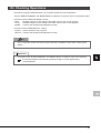
HOW TO READ THIS GUIDE
The following table lists symbols used in this guide with descriptions and examples.
Symbol
P oint
Description
Shows information you need to
know.
Example
The C Controller module executes program operation
regardless of the switch status (RUN/STOP).
Refer to the following.
Reference
Shows reference manuals and
pages on which you can find the
details.
C Controller Module User's Manual
(Hardware Design, Function Explanation)
: SH-080766ENG
Terminology
Caution
[ ]
Shows the explanations of
terminology.
Buffer memory: The memory of an intelligent function
module used to store data (such as
setting values and monitored values)
for communication with a C
Controller module
Shows descriptions that must be
noted.
Power off the system before mounting a module.
Menu names on the menu bar
([ ][ ] shows drop-down menus.)
Select [Project][Properties].
Buttons on the window
Keys on the keyboard
button
F4
key
1
INTRODUCTION
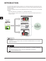
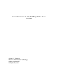
This guide simply explains the basic operations of a C Controller module for the first-time users of the
Mitsubishi programmable controller MELSEC-Q series C Controller module (hereafter abbreviated as C
Controller module).
This guide is targeted for users who use the MELSEC-Q series for the first time and are in the following
situations:
• Users with experience in C language or C++ language programming
• Users considering to replace the microcomputer board or the personal computer system with a C
Controller system
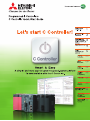
Mounting and wiring modules
Quick Start
Guide
100VAC
24VDC
Creating programs
/* Open the bus.
sRet = QBF_Open( CPU_TYPE, &lPath );
if( sRet != n ){
:
/* Output control and 7-segment LED con
for( i = 0; i < 20; i++ ){
/* Output control
sRet = QBF_Y_Out_WordEx( lPath,
:
All
information is
included!
Checking operations
Reference
● Precautions
For safe use of the C Controller module, read "SAFETY PRECAUTIONS" in the C Controller
Module User's Manual.
Caution
This guide explains operations using the system configuration in "<2> System Configuration"
(P.15).
When designing/operating a system, refer to the manuals listed in the following.
"RELATED MANUALS"(P.12)
2
CONTENTS
1 HOW TO READ THIS GUIDE
1
2 INTRODUCTION
2
3 OPERATIONS THAT CAN BE PERFORMED USING C CONTROLLER MODULE
5
■Sophisticated and high-speed processes and communications with the higher server .............. 5
■Various functions for real-time control ......................................................................................... 6
■Features ...................................................................................................................................... 6
4 RELATED MANUALS
12
■Learning about a C Controller module....................................................................................... 12
■Learning about CW Workbench ................................................................................................ 12
5 USING C CONTROLLER MODULE
13
<1> Preparing for Operation ........................................................................................................ 14
<2> System Configuration............................................................................................................ 15
1) System configuration example.......................................................................................... 15
2) Mounting the modules....................................................................................................... 16
3) Wiring the modules ........................................................................................................... 17
4) Checking the power supply module .................................................................................. 19
<3> Setting the Module ................................................................................................................ 21
1) Initializing the C Controller module ................................................................................... 21
2) Setting parameters............................................................................................................ 23
<4> Knowledge Required for Programming ................................................................................. 26
<5> Programming ........................................................................................................................ 29
1) Creating a project.............................................................................................................. 32
2) Creating a user program ................................................................................................... 36
3) Generating an execution module from the user program ................................................. 37
4) Connecting a C Controller module to CW Workbench...................................................... 38
5) Debugging the user program ............................................................................................ 40
6) Registering an execution module...................................................................................... 45
<6> Checking Operations ............................................................................................................ 47
6 FREQUENTLY-USED FUNCTIONS
50
<1> Checking Errors and Taking Corrective Action ..................................................................... 50
1) How to check an error and take corrective action............................................................. 50
2) Checking error history....................................................................................................... 52
<2> Monitoring Module Status and Testing Operations ............................................................... 53
1) Checking module I/O status and buffer memory status .................................................... 53
2) Testing operations by forced output.................................................................................. 55
3
MEMO
4
OPERATIONS THAT CAN BE PERFORMED
USING C CONTROLLER MODULE
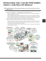
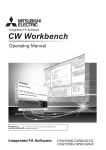
■ Sophisticated and high-speed processes and communications with the
higher server
A C Controller module is a CPU module that supervises MELSEC-Q series modules and controls I/O
devices using C language or C++ language program. This module also can:
• Reuse a C language or C++ language program developed under a microcomputer board and
personal computer environment.
• Perform sophisticated and high-speed operation process, which is hard for ladder programs to
handle, required in the fields such as manufacturing of semiconductor products, FPDs, and solar
cells; and remote monitoring of public infrastructures (e.g. electricity, gas, and water systems).
The C Controller module easily achieves various functions using user programs.
Combined with partner products, the module can also perform the following functions.
• Program-free SECS communication commonly used for semiconductor manufacturing and direct
communication with the higher server without a gateway personal computer can be executed
through a SECS communication software package.
• In collaboration with a vision system, image distinction and product inspection can be performed
without a personal computer.
Semiconductor
manufacturing
FPD manufacturing
Data collection
Equipment controller (for
data collection)
Sensor
network
The
development
cost is reduced by
reusing C language
program
resources.
High-speed
operation process,
which is hard for
ladder programs to
handle, can be
performed.
SECS communication
(Ethernet)
Can be executed only
with tool settings.
A SECS
communication
gateway is
established,
saving cost and
space.
Higher server
Field network
Operation/control
Equipment controller (for
transportation, loading/unloading)
Using the
field network and
the sensor network allows
high-speed data collection
with minimal wiring.
FPD image inspection
Image distinction in collaboration
with the vision system
Image
distinction and
product inspection
can be performed
without a personal
computer.
Motion network
High-speed
synchronized
communications
with a servo amplifier
is available.
Servo
Machine
vision
Spacesaving and
environmentallyresistant
system
Ethernet
The high-speed
(maximum 1Gbps) and
large-capacity controller
network reduces
takt time.
Controller-to-controller
network in equipment
5
■ Various functions for real-time control
The C Controller module equips VxWorks (Wind River Systems, Inc.), real-time OS with many
achievements and high reliability (The runtime license does not cost).
Since VxWorks supports a preemptive system*1, allowing real-time operation and sophisticated process
that require an interrupt and punctuality, which may not be ensured under personal computer
environment.
VxWorks also equips various functions, such as file access, drivers for the network functions, I/O and
communication libraries, and therefore can be used for various purposes.
*1 A system that equally assigns execution time to multiple programs so that the processor (CPU) may
not be dedicated to one program
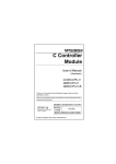
■ Features
1. Flexible system configuration using various MELSEC-Q series modules
In a C Controller system, program resources can be reused and various MELSEC-Q series modules are
available, making system configuration easier.
Microcomputer board and personal
computer environment
Short p
rodu
life cyc ct
le
le
Availab ited
lim
re
a
w
hard
are
n hardw ment
tions o
Restric s and environ
er.
ation
ion hard
specific
extens
makes
C Controller system
I/O
module
High-speed
input, interrupt
input, AC/DC...
More than
44 models
Analog
module
A/D conversion,
D/A conversion,
temperature
control...More
than 26 models
Network
module
Controller-tocontroller
network, wiresaving system,
sensor...More
than 16 models
Positioning Other modules
such as an
module
4 axes, 8 axes, information
16 axes, pulse module
input, differential Logging, MES
output...More
communication,
than 25 models serial communication
...More than 4 models
Discon
tinua
boards tion of
/chips
So hard on
configuring
a system!
Flexible system configuration using
various MELSEC-Q series modules
Power supply module
Trouble
so
remova me installatio
l work
n/
Base unit
longliable,
High-re stable supply
nd
term, a
n base asier.
xtensio
e
Using e es extension
k
a
units m
6
Slotted
in
easily
2. Equipped OS, drivers, and libraries allow you to focus on developing user
programs
Since OS and communication drivers have been equipped with a C Controller module, you are no
longer bothered with troublesome work under microcomputer board and personal computer
environment (OS porting, driver development, OS writing to ROM) and can focus on developing a user
program.
The C Controller module can easily access MELSEC-Q series modules using library functions
dedicated for a C Controller module (bus interface function, MELSEC communication function).
Microcomputer board and personal
computer environment
User
program
and
drivers
ted,and
be crea r each board.
t
s
u
m
An OS
ired fo
are requ
libraries
OS (must be changed
depending on system
configuration.)
Library
Analog
driver
Analog
board
Library
I/O
driver
I/O
board
Must be
co
the syste rrected whene
ver
m is cha
nged.
C Controller system
User program
Library
Analog
I/O
driver
driver
Network
driver
Already
equipped
OS(VxWorks)
Library
Library
Network
board
to
need is gram.
All you
user pro
a
te
a
cre
Library
Network
driver
Access to the modules is...
Much work
Troublesome
Y output
d using
nipulate nctions.
a
m
y
il
Eas
ry fu
ted libra
dedica
Write Y output data.
Easy
Quick start
7
3. Initialization, parameter settings, monitoring, and testing can be executed
without a program
Complex programs for the initialization and the system settings of a C Controller module, and parameter
settings of a network module are not required. The operations can be easily executed on view-friendly
setting/monitoring tool for C Controller module.
Programs to check module status, errors occurred in a C Controller module and in a user program,
cable disconnection, and communication status are also not required.
Microcomputer board and personal
computer environment
Do I have to
create
programs all
over again?
C Controller system
A program
is required for
each operation.
Ethernet
Setting/monitoring tool for
C Controller module
Monitoring
/* Md.31 Status information
printf("Status
[Md.31 ]");
printf("%7s0x%04hX%8s0x%04hX%8s0x
/* Specify the QD75M or the QD75MH.
if( (sType == UNITTYPE_QD75M) || (s
/* Md.108 Servo status information
printf("ServoStatus [Md.108]"
printf("%7s0x%04hX%8s0x%04hX%8s
Diagnostic/
error history
Monitoring
Testing
Parameter settings
Self-making
Initialization
int nRet;
DWORD nLen;
ULONG ulBoardNo = 0;
// Fu
// Bi
// Bo
// Initialize the board numbered "0".
nRet = GpibOpen( ulBoardNo );
if (nRet) {
printf("
printf( : %d\n", n
ulSize = (unsigned long)(PARAM
ulBufSize = 0;
sRet=QBF_ToBuf( lPath, usIoNo / 16,
ulSize, (unsigned s
ulBufSize);
Parameter
settings
/* Judge writing.
if(sRet != 0){
printf("Parameter area write er
Program creation/correction
Troublesome
steps
Parameter settings
Compilation
Download
Debugging
8
If an
error or any
correction is
found, you must
start all over
again.
ulSize = (unsigned long)(PARAM
ulBufSize = 0;
sRet=QBF_ToBuf( lPath, usIoNo / 16,
ulSize, (unsigned s
ulBufSize);
/* Judge writing.
if(sRet != 0){
printf("Parameter area write er
Monitoring
Initialization
/* Md.31 Status information
printf("Status
[Md.31 ]");
printf("%7s0x%04hX%8s0x%04hX%8s0x
int nRet;
DWORD nLen;
ULONG ulBoardNo = 0;
/* Specify the QD75M or the QD75MH.
if( (sType == UNITTYPE_QD75M) || (s
/* Md.108 Servo status information
printf("ServoStatus [Md.108]"
printf("%7s0x%04hX%8s0x%04hX%8s
// Initialize the board numbered "0".
nRet = GpibOpen( ulBoardNo );
if (nRet) {
printf("
printf( : %d\n", n
// Fu
// Bi
// Bo
Included
in one
tool.
Monitoring and settings can be executed
on the view-friendly tool.
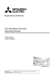
4. Quick start using an integrated development environment, "CW Workbench"
An engineering tool for C Controller, "CW Workbench", equips basic functions such as program editing,
generation of execution module, and debugging. A user program for a C Controller module is easily
developed.
Eclipse-based CW Workbench allows function enhancement using a third-party plug-in software.
"Editor" window
CW Workbench
"Debug" window
Program editing
Debugging
"Project Explorer" window
"Breakpoints" window
Project management and settings
Breakpoint management
"Remote Systems" window
Connection to the C Controller module
Ethernet
"Build Console" window
Display of build progress
Personal computer
The plug-in feature
allows multilingualization of
menu items and source
code management.
"Variables" window
Display of the current local variable value
"Registers" window
Display of the current register value
"Expressions" window
Display of the current variable value
registered for viewing
"Memory Browse" window
Display of the memory dump on
the C Controller module
9
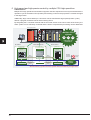
5. High-speed and high-precise control by multiple CPU high speed bus
transmission
Multiple CPU high speed bus transmission supports real-time sequential control synchronized with the
operation cycle of the Motion CPU (0.88ms) and tracking control to keep up with the constant changes
in the target value.
Additionally, large volume data up to 14K words can be transferred at high speed (0.88ms cycles)
without a program, and data can be shared among CPUs.
By integrating the C Controller module with the CPU that serves as the nerve center of the factory, the
entire system can be efficiently controlled and the load of computational processing can be distributed.
Power supply module
Multiple CPU
system
I/O
control
Information control
Programmable
controller CPU
Motion CPU
Motion
program
C language
program
Direct
command
Dedicated library
function
Large
volume data
Shared memory
Servo control
C Controller CPU
(C Controller module)
Ladder
program
High-speed
transfer
Servo
control
Integrates all
controllers!
Ethernet
I/O control
Information
control
Mitsubishi
integrated
FA solution
Direct
command
Large
volume data
Shared memory
High-speed
transfer
Shared memory
-compatible
controllers
0.88ms
cycles
Shared memory system as if the system was controlled by a single CPU
10
6. Wide application using partner products
In combination with the following partner products, higher functionality and easy information link can be
achieved.
(1) Information link with SECS communication software package (CIMOPERATOR SECS+)
Introduction of CIMOPERATOR achieves personal computer-free and program-free SECS
communication (GEM*1/non-GEM) with the higher server, enabling status management and
information collection of manufacturing equipment.
*1 One of the industry-standard communication protocol used in semiconductor manufacturing lines
Microcomputer board and
personal computer environment
Higher
server
C Controller system
Higher
server
SECS communication costs
time, effort, and money.
A
personal
computer
is required.
Personal computer-free
environment
Direct SECS communication can
be performed by implementing
the CIMOPERATOR execution
module on a C Controller module.
A program
performing SECS
communication is
required on a
gateway personal
computer.
Install CIMOPERATOR on the
CompactFlash card.
Personal
computer-free
SECS
communication
Load o
n
a perso operating
nal com
puter
Easy settings without
a program
GEM can be defined only
by tool settings.
By defining a unique frame,
communications using a standard
other than GEM can be made.
p
Hang-u
Failure
Massiv
commu e volume of
nicatio
n progra
ms
Decrease in the cost
and size of the system
costs
pment
Develo ases.
re
inc
Setting the C Controller module
as a SECS communication
gateway leads to cost-saving
and space-saving system.
Installa
tion sp
person
ace fo
al com
puter is r the
require
d.
Manufacturing
equipment
Manufacturing
equipment
Nippon Denno
Co.,Ltd
(2) Collaboration with the vision system (COGNEX In-Sight EZ, In-Sight Micro, and In-Sight5000 series)
Collaboration of the COGNEX machine vision with the C Controller module can easily automate
manufacturing processes including measurement, inspection, and distinction of products.
By sending commands using a C language
program, pictures and images can be imported.
In-Sight EZ series
Collaborating with the integrated
image processor, machine vision.
In-Sight
Micro series
HUB
Ethernet
connection
available
In-Sight 5000 series
One cable serves as both a communication
cable and a power cable.
Cognex Corporation
11
RELATED MANUALS
This guide explains the basic operations of a C Controller module.
To make maximum use of the C Controller module, refer to the following.
■ Learning about a C Controller module
● C Controller Module User's Manual (Hardware Design, Function Explanation)
................................................................................................................................... SH-080766ENG
This manual explains the system configuration, specifications, functions, handling, wiring,
and troubleshooting of a C Controller module.
● C Controller Module User's Manual (Utility Operation, Programming)
.....................................................................................................................................SH-080767ENG
This manual explains the installation and uninstallation of SWPVC-CCPU, utility
operations, and functions and programming using SWPVC-CCPU.
■ Learning about CW Workbench
● CW Workbench Operating Manual ............................................................................ SH-080982ENG
This manual explains the system configuration, installation and uninstallation, specifications,
functions, and troubleshooting of CW Workbench.
12
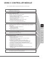
USING C CONTROLLER MODULE
The C Controller module is installed with procedures as shown below.
<1> Preparing for Operation (P.14)
Preparing the necessary devices
<2> System Configuration (P.15)
Installing, wiring, and powering on the devices
1) System configuration example (P.15)
Showing the example of system configuration used in this guide
2) Mounting the modules (P.16)
Mounting the prepared modules on a base unit
3) Wiring the modules (P.17)
Wiring the power supply module and the output module
4) Checking the power supply module (P.19)
Powering on the system and checking module status
<3> Setting the Module (P.21)
Configuring settings to operate the C Controller module using C Controller
setting utility
1) Initializing the C Controller module (P.21)
Preparing a standard RAM
2) Setting parameters (P.23)
Setting parameters for the C Controller module
<4> Knowledge Required for Programming (P.26)
Explaining the bus interface function
<5> Programming (P.29)
Creating a program using CW Workbench
1) Creating a project (P.32)
Starting CW Workbench, creating projects, and configure settings
2) Creating a user program (P.36)
Creating a user program that controls a C Controller system.
3) Generating an execution module from the user program (P.37)
Converting (Building) the created program into an executable module
4) Connecting a C Controller module to CW Workbench (P.38)
Connecting a C Controller module to CW Workbench to perform debugging
5) Debugging the user program (P.40)
Checking operations of the created program
6) Registering an execution module (P.45)
Building the created program for operation and storing the program on the C
Controller module
<6> Checking Operations (P.47)
Executing the program and checking operations
13
<1> Preparing for Operation
Prepare the necessary devices.
1) C Controller system
2) Personal computer
3) SW
PVC-CCPU*2
QY40P
01234567
89ABCDEF
0
1
2
3
4
5
6
7
8
9
A
B
C
D
E
F
COM
12VDC
24VDC
0 . 1A
For modules, refer to the
next page.
4) CW Workbench
Installation*1
Windows -installed
personal computer
5) Ethernet cable
Installation*1
Either a straight cable or
a cross cable
*1 Install SWPVC-CCPU and CW Workbench on the same personal computer beforehand.
Reference
For installation of SWPVC-CCPU, refer to the following.
C Controller Module User's Manual (Utility Operation, Programming): SH-080767ENG
For installation of CW Workbench, refer to the following.
CW Workbench Operating Manual: SH-080982ENG
*2 SWPVC-CCPU is a setting/monitoring tool for C Controller module.
14
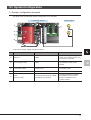
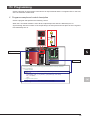
<2> System Configuration
1) System configuration example
This guide uses the following system configuration as an example.
Lamps (output)
C Controller system
1)
4)
2)
3)
5)
*A wire to the power supply module is omitted.
No.
Name
Model
Description
1)
Base unit
Q33B
A unit on which a power supply
module, a C Controller module, and
I/O modules are mounted
2)
Power supply module
Q62P
Supplies power to modules such as
a C Controller module and I/O
modules.
3)
C Controller module
Q12DCCPU-V
Supervises the control process of a
C Controller system.
4)
Output module
QY40P
Cable
An Ethernet cable meeting 10BASET/100BASE-TX standards
5)
(Ethernet cable)
Connects the personal computer
with SWPVC-CCPU and CW
Workbench installed to the C
Controller module.
15
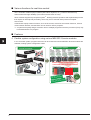
2) Mounting the modules
Mount the prepared modules on a base unit.
When using the C Controller module for the first time, connect a battery connector.
Caution
● Mount a battery before operation.
● Power off the system before mounting a module.
P oint
● Mounting a battery to the C Controller module
1) Open the cover at the bottom
of the C Controller module.
C Controller
module side
connector
2)
2) Insert the battery side
connector into the C Controller
module side connector in
correct orientation.
Battery
Battery side
connector
1)
3) Close the cover at the bottom
of the C Controller module.
End
1) Insert the module fixing
projection into the module
fixing hole on the base unit.
3)
Bottom of
the C Controller module
Base unit
Module
Side view
Base unit
Module fixing
projection
2) Fully insert the module fixing
projection in the arrow direction
and press the module until the
projection snaps into place.
Module
Module fixing
fixing hole
projection
Module
fixing hole
Module
Side view
End
Reference
For how to remove a module, refer to the following.
QCPU User's Manual (Hardware Design, Maintenance and Inspection): SH-080483ENG
16
3) Wiring the modules
Wire the power supply module.
Caution
Power off the system before wiring the module.
Reference
For wiring precautions, refer to the following.
QCPU User's Manual (Hardware Design, Maintenance and Inspection): SH-080483ENG
1. Wiring the power supply module
The following shows an example of wiring the power wire and the ground wire to the base unit.
Provide grounding to prevent electric shock and malfunction.
Power supply module
(Q62P)
1) Connect a 100VACpower supply to the
power input
terminal.
2) Ground LG and
FG terminals.
ERR
2) FG
100VAC
2) LG
1) INPUT
100-120VAC
AC
Ground
wire
Grounding
2. Wiring the output module
The following shows an example of wiring the output module (QY40P).
Lamp 1
Signal: Y00
L
Lamp 2
Signal: Y01
L
+
-
17
P oint
Wire the power supply line of the output device and that of the C Controller system
separately as shown below.
Main
power
supply
100VAC
200VAC
Relay
terminal
block
Power supply of Insulation
the C Controller transformer
system
C Controller
system
T1
Output power supply
Output device
Inside of a control panel
18
4) Checking the power supply module
Check that the power supply module runs normally after installing the system, mounting the modules,
and wiring the system.
Operating procedure
1. Check the following before powering on the system.
• Wiring to the power supply module
• Power supply voltage
2. Set the C Controller module to STOP.
Open the cover on the front of the C Controller
module and set the "RUN/STOP/MODE" switch to
"STOP".
"RUN/STOP/MODE" switch
3. Power on the power supply module.
4. Check that the power supply module runs normally.
Check the front LED on each module.
The following lists the normal status of the LEDs.
1) Power supply module: The "POWER" LED lights in
green.
2) C Controller module: The "MODE" LED lights in
green.
1)
2)
When the C Controller module is the default (the
standard RAM has not been initialized), the 7segment LED displays a flashing "01". However, this
does not mean a problem in this step.
The LED turns off after the module is initialized.
"<3> Setting the Module" (P.21)
Construction of the system is ended.
P oint
If the "POWER" LED of the power supply module remains off even after power-on, check that
the power supply module is correctly wired and mounted.
19
Reference
If the "ERR." LED turns on or starts flashing, troubleshoot with reference to the following.
C Controller Module User's Manual (Hardware Design, Function Explanation)
: SH-080766ENG
20
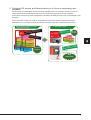
<3> Setting the Module
Configure settings to operate the C Controller module.
1) Initializing the C Controller module
Prepare a standard RAM for the C Controller module.
Caution
All files in the standard RAM are erased by module initialization.
Operating procedure
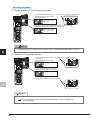
1) Open the cover on the module front and set the
"RESET/SELECT" switch to "RESET".
4) Check that the "MODE" LED lights in "orange", and
the 7-segment LED displays "00".
RUN : OFF
MODE : Lights in orange.
USER : OFF
Set the switch to "RESET".
"RESET/SELECT" switch
5) Release the "RUN/STOP/MODE" switch.
2) Check that the "MODE" LED is off.
The switch returns to the "STOP" position.
6) Repeatedly set the "RESET/SELECT" switch to
RUN : OFF
MODE : OFF
USER : OFF
"SELECT" until the 7-segment LED displays "11"
("module initialization setting" mode).
3) Holding the "RUN/STOP/MODE" switch on the
"MODE" position, set the "RESET/SELECT" switch
to the center.
Repeatedly set the switch to "SELECT".
"RUN/STOP/MODE" switch
Hold the switch on the "MODE" position.
"RESET/SELECT" switch
RUN : OFF
MODE : Lights in orange.
USER : OFF
Return the switch to the center.
"RESET/SELECT" switch
21
7) Set the "RUN/STOP/MODE" switch to "RUN" and
9) Resetting the C Controller module will format the
initialize the module. The "RUN" LED will be
flashing during initialization.
standard RAM.
The "RUN" LED and the "USER" LED start flashing
in green.
"RUN/STOP/MODE" switch
Set the switch to "RUN".
RUN : Flashes in green.
MODE : Lights in green.
USER : Flashes in green.
RUN : Flashes in green.
MODE : Lights in orange.
USER : OFF
10) When the formatting is ended, the "RUN" LED and
the "USER" LED end flashing, and the "MODE"
LED starts flashing in green.
RUN : OFF
MODE : Flashes in green.
USER : OFF
8) Check that the "RUN" LED turns off, and the 7segment LED displays "00". Reset the C Controller
module.
RUN : OFF
MODE : Lights in orange.
USER : OFF
11) Reset the C Controller module.
When the formatting is completed, the "RUN" LED
and the "MODE" LED light in green.
RUN : Lights in green.
MODE : Lights in green.
USER : OFF
P oint
Resetting procedure
1) Set the "RESET/SELECT" switch on the front of the C
Controller module to "RESET".
2) Check that the "MODE" LED
turns off.
[Reset end status]
"RESET/SELECT" switch
MODE: OFF
3) Set the "RESET/SELECT" switch
to the center.
"RESET/SELECT" switch
Caution
Do not operate the switches using a sharp-pointed tool such as a driver.
Doing so may damage the switches.
22
2) Setting parameters
Set parameters for the C Controller module.
Terminology
Parameter: Setting data required for a C Controller system to operate.
Set modules and a network in a C Controller system using C Controller setting
utility.
1. Connecting a C Controller module to a personal computer
Connect CH1 of the C Controller module to a personal computer using an Ethernet cable.
Personal computer
C Controller
module
Caution
The IP address of the C Controller module and that of the personal computer must be set to
the same segment.
Since this guide uses the default IP address for the C Controller module (192.168.3.3), set the
IP address for the personal computer to "192.168.3.* (*: other than 0, 3, and 255)".
Set the subnet mask for the personal computer to "255.255.255.0".
Reference
For how to change an IP address, refer to the following.
C Controller Module User's Manual (Hardware Design, Function Explanation)
: SH-080766ENG
23
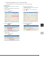
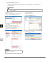
2. Starting C Controller setting utility
Operating procedure
1) Select [start][All Programs][MELSEC][C
Controller][C Controller setting utility].
8) Click the
button.
1)
8)
The "Specify CPU type" window appears.
2) Select "Q12DCCPU-V".
3) Click the
button.
3)
2)
The "Connection settings" window appears.
4) Select the "Write authority" check box.
5) Enter "target".
6) Enter "password".
7) Click the
button.
4)
5)
6)
7)
24
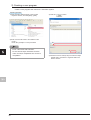
The "C Controller setting utility" window appears.
3. Writing the parameters to the C Controller module
Write the parameters to the C Controller module using C Controller setting utility.
Operating procedure
1) Select the "Online operation" tab in C Controller
setting utility.
2) Select the "Clear all parameters of all drives prior to
writing." check box.
3) Click the
6) Reset the C Controller module.
After resetting the C Controller module, the written
parameters will be valid.
7) Click the
button to exit C Controller setting
utility.
button.
7)
1)
2)
4) Click the
button.
3)
8) The following window appears.
Click the
button.
8)
4)
5) When the writing is completed, the following
window appears.
Click the
button.
5)
25
<4> Knowledge Required for Programming
1. Bus interface functions
The bus interface function is a library function dedicated for a C Controller module.
Using this function in a user program allows a C Controller module to easily control MELSEC-Q series
modules.
(1) Opening/closing a bus
To use the functions, open a bus at the start of the program and close the bus at the end of the program.
Functions to open/close a bus
Name
Function
QBF_Open
Opens a bus.
QBF_Close
Closes a bus.
P oint
Open or close a bus (QBF_Open/QBF_Close functions) once at the start of a program and at
the end of a program, respectively.
By using these functions only once, communication performance will be improved.
(2) I/O access
1-point access and 1-word access are available.
1) 1-point access: A function that treats 1-point data (ON/OFF of switches and lamps)
Example of 1-point access functions
Name
Function
QBF_X_In_BitEx
Reads an input signal (X) in units of one point.
QBF_Y_Out_BitEx
Outputs an output signal (Y) in units of one point.
QBF_Y_In_Bit_Ex
Reads an output signal (Y) in units of one point.
2) 1-word access: A function that treats 1-word (16 bits) data (numeric values, characters)
Example of 1-word access functions
Name
Function
QBF_X_In_WordEx
Reads an input signal (X) in units of words.
QBF_Y_Out_WordEx
Outputs an output signal (Y) in units of words.
QBF_Y_In_WordEx
Reads an output signal (Y) in units of words.
(3) User LED control
USER LED control and 7-segment LED control are available.
Example of user LED control functions
Name
26
Function
QBF_ControlLED
Controls the "USER" LED of a C Controller module.
QBF_Control7SegLED
Controls the 7-segment LED of a C Controller module.
Reference
Only the basic bus interface functions are explained in this section.
Bus interface function for controlling modules and the MELSEC communication function are
also available.
Bus interface function help window and MELSEC communication function help window in
SWPVC-CCPU
C Controller Module User's Manual (Utility Operation, Programming): SH-080767ENG
2. Bus interface functions used in this guide
Basic bus interface functions, output access and 7-segment LED control, are used in the program
created in this guide.
• Opening/closing a bus: QBF_Open/QBF_Close functions
• Output access: QBF_Y_Out_WordEx function
• 7-segment LED control: QBF_Control7SegLED function
27
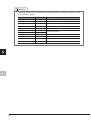
Reference
The following data types are available for C language and C++ language programming used
on a C Controller module.
Data type
Designation
byte
8
Unsigned integer
char
8
Character string
unsigned char
8
Unsigned character string
short
16
Signed short integer
unsigned short
16
Unsigned short integer
int
32
long
32
unsigned long
32
Unsigned (long) integer
float
32
Single-precision real number
double
64
Double-precision real number
void
28
Bit width
-
Signed (long) integer
-
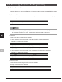
<5> Programming
Create a program in which lamps connected to an output module and the 7-segment LED on the front
of the C Controller module flash.
1. Program example and control description
Create a program that performs the following control.
When the C Controller module is set to RUN, output lamps Y00 and Y01 alternately turn on.
Synchronizing with the on status of the output lamps, the tens place and ones place of the 7-segment
LED alternately turn on.
Y00
Alternately turns on.
Y01
7-segment LED control
Output access
/* Perform an output control and 7-segment LED control in turns by 20 times.
for(i = 0; i < 20; i++){
/* Output control
sRet = QBF_Y_Out_WordEx(lPath, NORMAL_ACCESS, UNIT_XY, WORD, &usDataBuf, DUMMY);
if(sRet != 0){
printf("ERROR : QBF_Y_Out_WordEx_1 [%d(%04hxH)]\n", sRet, sRet);
QBF_Close(lPath);
return;
/* 7-segment LED control
sRet = QBF_Control7SegLED(lPath, MODE_MANUAL, &pcdata[0]);
if(sRet != 0){
29
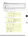
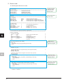
2. Source code
The following describes source codes.
/***********************************************************************************************************************/
/* Function header
*/
/***********************************************************************************************************************/
#include <vxworks.h>
/* VxWorks function header
*/
#include <taskLib.h>
/* VxWorks function header
*/
#include <stdio.h>
/* Standard function header
*/
#include "QbfFunc.h"
/* Bus interface function header
*/
/***********************************************************************************************************************/
/* Definition
*/
/***********************************************************************************************************************/
/* For debugging
*/
#define UNIT_XY
0x0000
/* Start I/O number of the module
*/
#define QY_LED
0x5555
/* Initial output value of Y signal (even bit: on)
*/
#define SEG_LED1
0xFF
/* Initial output value of 7-segment LED (ones place)
*/
#define SEG_LED2
0x00
/* Initial output value of 7-segment LED (tens place)
*/
Declare the file that
defined a function
list for use of the
library function.
Define values used
for the control.
/***********************************************************************************************************************/
/* For QBF function
*/
#define CPU_TYPE
2
/* CPU identification flag (CCPU: 2)
*/
#define WORD
1
/* 1-word specification
*/
#define NORMAL_ACCESS
0
/* General access specification
*/
#define DUMMY
0
/* Dummy
*/
#define MODE_MANUAL
0
/* 7-segment LED control mode
*/
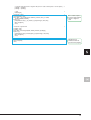
/***********************************************************************************************************************/
/* Process outputs from Y signal and control the 7-segment LED.
*/
/***********************************************************************************************************************/
void Q12_SampleTask()
{
/* Declare local variables.
*/
short
sRet;
/* Return value of the QBF function
*/
long
lPath;
/* Path of a bus
*/
unsigned short usDataBuf;
/* Y signal (in units of words)
*/
unsigned short usEmptyDataBuf;
/* For reset of Y signal
*/
char
pcdata[2];
/* 7-segment LED on value
*/
short
i;
/* For loop
*/
/* Open the bus.
sRet = QBF_Open(CPU_TYPE, &lPath);
if(sRet != 0){
printf("ERROR : QBF_Open [%d(%04hxH)]\n", sRet, sRet);
return;
}
*/
/* Set the output signal (Y) value (turn on the even bit).
usDataBuf = QY_LED;
*/
/* Set the output value of the 7-segment LED (only the ones places are all lit).
pcdata[0] = SEG_LED1;
pcdata[1] = SEG_LED2;
*/
/* Perform an output control and 7-segment LED control in turns by 20 times.
*/
for(i = 0; i < 20; i++){
/* Output control
*/
sRet = QBF_Y_Out_WordEx(lPath, NORMAL_ACCESS, UNIT_XY, WORD, &usDataBuf, DUMMY);
if(sRet != 0){
printf("ERROR : QBF_Y_Out_WordEx_1 [%d(%04hxH)]\n", sRet, sRet);
QBF_Close(lPath);
return;
}
30
/* 7-segment LED control
sRet = QBF_Control7SegLED(lPath, MODE_MANUAL, &pcdata[0]);
if(sRet != 0){
printf("ERROR : QBF_Control7SegLED_1 [%d(%04hxH)]\n", sRet, sRet);
QBF_Close(lPath);
return;
}
*/
/* Invert the output signal (Y) value (turn on the bits in order of odd bit -> even bit ->...).
usDataBuf = ~usDataBuf;
*/
Enable the bus
interface function at the
start of the program.
Control the output
module using the bus
interface function.
Control the 7-segment
LED using the bus
interface function.
/* Invert the output values of the 7-segment LED (turn on in order of all ones places -> all tens places...). */
pcdata[0] = ~pcdata[0];
pcdata[1] = ~pcdata[1];
/* Wait.
taskDelay(40);
}
/* Reset the Y signal.
usEmptyDataBuf = 0x00;
sRet = QBF_Y_Out_WordEx(lPath, NORMAL_ACCESS, UNIT_XY, WORD,
&usEmptyDataBuf, DUMMY);
if(sRet != 0){
printf("ERROR : QBF_Y_Out_WordEx_2 [%d(%04hxH)]\n", sRet, sRet);
QBF_Close(lPath);
return;
}
}
*/
*/
/* Reset the 7-segment LED.
pcdata[0] = 0x00;
pcdata[1] = 0x00;
sRet = QBF_Control7SegLED(lPath, MODE_MANUAL, &pcdata[0]);
if(sRet != 0){
printf("ERROR : QBF_Control7SegLED_2 [%d(%04hxH)]\n", sRet, sRet);
QBF_Close(lPath);
return;
}
*/
/* Close the bus.
QBF_Close(lPath);
return;
*/
Turn off both outputs
from the output module
and the 7-segment
LED.
Disable the bus
interface function at
the end of the program.
31
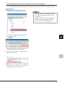
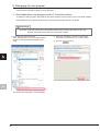
1) Creating a project
1. Starting CW Workbench
Operating procedure
1) Select [start][All Programs][Wind River][CW
Workbench][CW Workbench].
1)
2) Enter the storage location of the workspace.
In this procedure, enter "C:\WindRiver\workspace".
3) Click the
button.
2)
3)
4) Click the
button.
4)
The main window of CW Workbench appears.
32
Reference
• The default window sizes and icon
positions on CW Workbench depends on
a personal computer. If a window size
differs from that shown in this guide,
adjust the size.
• To default an enlarged/deleted window,
select [Window][New Window].
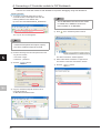
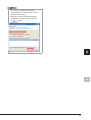
2. Creating a project
Operating procedure
1) Select [File][New][Wind River Workbench
Project...].
6) Enter a project name.
In this procedure, enter "Q12_SampleProject".
1)
7) Click the
button.
6)
2) Select "Wind River VxWorks6.4".
3) Click the
button.
7)
2)
The project has been created.
3)
4) Select "Downloadable Kernel Module".
5) Click the
button.
4)
5)
33
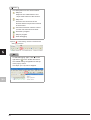
3. Creating a project property
Configure settings to convert (build) the created project into a module that can be executed on a C
Controller module.
Terminology
Build: An operation that compiles source codes according to a processor and links the code to
the include file.
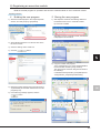
(1) Setting the processor
(2) Setting a include file
1) Select the created project in the "Project Explorer"
window, and click [Project][Properties].
1) Click the "Build Paths" tab.
2) Click the
button.
1)
1)
2)
2) Select "Build Properties" from the tree view to the left
in the window.
3) Click the "Build Support and Specs" tab.
4) Select the "SH7750gnule" check box only in
"Available and enabled build specs:".
5) Select the "Debug mode" check box.
3) Click the
2)
3)
4)
5)
P oint
Clear the "Debug mode" check box for the
actual system operation.
34
button.
3)
4) Select the include folder dedicated for the C
Controller module in the "Select directory" window.
10) If the following message appears after clicking the
button, click the
button.
In this procedure, the folder is the one when
SWPVC-CCPU has been installed on
"C:\MELSEC".
5) Click the
button.
10)
The project property has been set.
4)
5)
6) Check that the folder specified in the "Select
directory" window has been selected.
7) Click the
button.
6)
7)
8) Check that the added include path is displayed in the
"Include paths:" area.
9) Click the
button.
8)
9)
35
2) Creating a user program
Create a user program that controls a C Controller system.
Operating procedure
1) Right-click the created project in the "Project
Explorer" window, and click [New][File].
3) Click the
button.
1)
2) Enter a source file name to be created in "File
name:".
Enter "Q12_Sample.c" in this procedure.
2)
P oint
Enter a file name with extension.
Do not use two-byte characters for a file
name. If used, a compilation error occurs in
compilation.
36
3)
4) Describe "Source code"(P.30) to access the output
module and to control the 7-segment LED in the
"Editor" window.
3) Generating an execution module from the user program
Convert (Build) the created program into a module that can be executed on a C Controller module.
Operating procedure
1) Right-click the created project in the "Project
Explorer" window, and click [Rebuild Project].
P oint
If "Build Finished..." is not displayed and an
error occurs, check the error and correct
the program.
After the correction, perform the operation
again from "3) Generating an execution
module from the user program"(P.37).
1)
2) If the message shown below appears, click the
button.
2)
The project starts to be built. The progress is
displayed in the "Build Console" window.
3) Check that "Build Finished..." is displayed in the
"Build Console" window.
3)
"Build Finished..." indicates the completion of
creation and build of the user program.
37
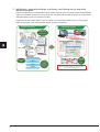
4) Connecting a C Controller module to CW Workbench
Connect a C Controller module to CW Workbench to perform debugging using CW Workbench.
Operating procedure
1) To acquire a VxWorks image file from the C
Controller module, start Explorer and enter the
following address in the address area.
ftp://192.168.3.3/SYSTEMROM/OS_IMAGEFILE/
P oint
The "C:\MELSEC\CCPU\DVx\Tools" folder
is created when SWPVC-CCPU has
been installed on "C:\MELSEC".
1)
5) Click
in the "Remote Systems" window.
The "Log On As" window appears.
P oint
To communicate between the C Controller
module and the personal computer, specify
the same VxWorks image file for both.
5)
2) Enter the following user name and password in the
"Log On As" window.
• User name : target
The "New Connection" window appears.
• Password : password
3) Click the
6) Select "Wind River VxWorks 6.x Target Server
Connection" in the "New Connection" window.
button.
7) Click the
button.
2)
3)
6)
4) Copy the VxWorks image file stored on the C
Controller module to
"C:\MELSEC\CCPU\DVx\Tools".
7)
4)
38
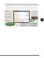
8) Set the following items in "Backend settings".
• Backend
12) Click the
button.
: wdbrpc
• Processor : SH7780 (Click the
button and select the processor.)
• IP address : 192.168.3.3 (default)
• Port
12)
: Blank
9) Select the "File" radio button in "Kernel image".
10) Click the
button.
13) Select the target server added in the "Remote
Systems" window, and click
8)
.
13)
10)
9)
The "Open File" window appears.
11) Select the VxWorks image file copied in the step 4)
(C:\MELSEC\CCPU\DVx\Tools) from the tree view,
and click the
14) After
is clicked, the connection is completed
when "connected - target server running" is
displayed at the bottom of the "Remote Systems"
window.
button.
11)
14)
P oint
If "connected - target server running" is not
displayed, check that the C Controller
module is normally powered on, and
perform the operation again from "4)
Connecting a C Controller module to CW
Workbench"(P.38).
39
5) Debugging the user program
Check that the created program correctly operates.
1. Downloading the user program on the C Controller module
To debug the user program, download the execution module on the memory in the C Controller module.
Downloading a user program allows users to execute the program without a script file.
Terminology
Script file: A file that describes the download location and the startup procedure of the user
program that starts at the start of a C Controller module
1) Right-click the created module file
"Q12_SampleProject.out" in the "Project Explorer"
window, and click [Download VxWorks Kernel
Task].
2) Select the "VxWorks6x_192.168.3.3 (Wind River
VxWorks 6.4)" check box only in "Launch Context:".
3) Click the
button.
2)
3)
1)
The "Download Configurations" window appears.
40
P oint
The "Launch Configuration Selection"
window appears on and after the second
operation of the step 2).
Select the "Launch the selected launch
configuration" radio button and click the
button.
41
2. Debugging the user program
1) Select the created project in the "Project Explorer"
window, and click
toolbar.
on the right side of
on the
6) Select the function that starts debugging
(Q12_SampleTask).
7) Click the
button.
2) Click [Debug Configurations...].
6)
1)
2)
The "Debug Configurations" window appears.
3) Click the downloaded module
"Q12_SampleProject.out" from "VxWorks Kernel
Task".
7)
8) Check that the function name selected in the step
6) has been selected in "Entry Point:".
9) Click the
button.
8)
3)
4) Select the target server indicating connection to the
C Controller module.
5) Click the
9)
button.
10) Debugging starts. Program execution stops at the
start of the function specified in "Entry Point:".
4)
5)
The "Entry Points" window appears.
42
10)
11) Click
in the "Debug" window to perform
debugging by one step.
<Debugging using breakpoint>
As well as debugging in units of one step
described in the step 11) shown to the left,
debugging using a breakpoint is available.
11)
12) By clicking a tab on the bottom right of the
"Variables" window*1. variable values can be
checked and changed.
In this step, check that "sRet", return value of the
"QBF_Open" function, is "0" (normal value).
1) Double-click the left edge of a source file window
and insert a breakpoint.
12)
1)
*1 Depending on a personal computer, the "Variables"
window appears as shown below. Adjust the
window size.
2) Click
.
2)
The program is executed at the position specified
by the breakpoint.
In the steps 11) and 12), debug the entire program.
Reference
If the return value of the bus interface
function is other than "0", troubleshoot with
reference to the following.
Bus interface function help window in
SWPVC-CCPU
C Controller Module User's Manual
(Hardware Design, Function
Explanation): SH-080766ENG
43
Reference
The descriptions of icons are as follows:
: Step Into
Steps into the called function and
stops at the first line of the function.
: Step Over
Executes the current line of the
function and then stops at the next line
of the function.
: Continues execution until the current
function has returned to its caller.
: Executes a program.
: Stops a program.
: Ends debugging.
13) Click
in the "Debug" window to terminate the
debugging session.
13)
P oint
To start debugging again, click
on the
right side of
on the toolbar and select
the created debug configuration at the top
of the pop-up menu.
The steps 1) to 10) can be skipped.
44
6) Registering an execution module
Build the created program for operation and store the created module on the C Controller module.
Operating procedure
1. Building the user program
1) Select the created project in the "Project Explorer"
window, and click [Project][Properties].
2. Storing the user program
1) Start Explorer and enter the following address in
the address area for the C Controller module.
ftp://192.168.3.3/RAM
1)
After login to the C Controller module, the address
is displayed as shown below.
1)
2) Select "Build Properties" from the tree view to the
left in the window.
3) Clear the "Debug mode" check box.
4) Click the
button.
2)
2) Copy the created user program
"Q12_SampleProject.out" on the standard RAM for
the C Controller module by drag and drop.
The user program created in this guide is stored on
the following:
C:\WindRiver\workspace\Q12_SampleProject\SH
7750gnule\Q12_SampleProject\NonDebug
3)
4)
5) Build the program following the procedure shown in
"3) Generating an execution module from the user
program"(P.37).
6) If the following message appears, click the
button.
2)
6)
45
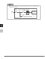
3. Creating and storing a script file
Create a script file that automatically downloads the
execution module at the start of the C Controller
module.
1) Open a text file and describe a script file that
downloads the user program and generates the
task as shown below.
Generate the
"Q12_SampleTask" function
with the default task name (t1)
Download the
"Q12_SampleProject.out"
file from the standard RAM.
2) Name the file as "STARTUP.CMD" and save the
file.
3) Copy the created script file on the standard RAM of
the C Controller module.
ftp://192.168.3.3/RAM
3)
The script file has been created and stored.
P oint
A user program and a script file can be
stored on the CompactFlash card as well.
When a script file is stored both the
standard RAM and the CompactFlash
card, one on the CompactFlash card is
started by priority.
46
<6> Checking Operations
Execute the program registered with the C Controller module and check operations.
Use the "RUN/STOP/MODE" and "RESET/SELECT" switches on the front of the C Controller module.
[Functions of the "RUN/STOP/MODE" switch]
• RUN
: Enables outputs (Y) and writing to the buffer memory from a user program
• STOP
: Disables outputs (Y) and writing to the buffer memory from a user program
• MODE : Used for the hardware self-diagnostic function
[Functions of the "RESET/SELECT" switch]
• RESET : Resets hardware and programs.
• SELECT : Used for the hardware self-diagnostic function
P oint
The C Controller module executes program operation regardless of the switch status (RUN/
STOP).
Reference
For details on the "RUN/STOP/MODE" and "RESET/SELECT" switches, refer to the following.
C Controller Module User's Manual (Hardware Design, Function Explanation)
: SH-080766ENG
47
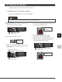
Operating procedure
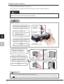
1. Enable outputs (Y) from the user program.
1) Set the "RUN/STOP/MODE" switch on the front of the C Controller module to "RUN".
LED display during the STOP status
(front cover closed)
"RUN/STOP/MODE" switch
MODE: Lights in green.
RUN : OFF
2) When the "RUN" LED lights in green, the program is running normally.
LED display during the RUN status (front cover closed)
MODE: Lights in green.
RUN : Lights in green.
P oint
To disable outputs (Y) from the user program, set the "RUN/STOP/MODE" switch to "STOP".
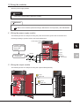
2. Reset the C Controller module.
1) Set the "RESET/SELECT" switch on the front of the C Controller module
to "RESET".
[During reset] (front cover closed)
MODE: Lights in green.
"RESET/SELECT" switch
2) Check that the "MODE" LED turns off.
[Reset completed] (front cover closed)
MODE: OFF
3) Set the "RESET/SELECT" switch to the center.
"RESET/SELECT" switch
Reference
If the "ERR." LED turns on or starts flashing, troubleshoot with reference to the following.
C Controller Module User's Manual (Hardware Design, Function Explanation)
: SH-080766ENG
48
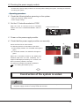
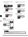
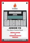
3. Use the 7-segment LED and lamps to check operations.
The 7-segment LED on the front of the C Controller module and output lamps operate as follows:
1) The tens place and ones place of the 7-segment LED alternately turn on by 20 times.
2) Synchronizing with the 7-segment LED, output lamps Y00 and Y01 alternately turn on.
Y00
Y01
QY40P
01234567
89ABCDEF
0
1
2
3
4
5
6
7
8
9
A
B
C
D
E
F
COM
12VDC
24VDC
0 . 1A
0
1
2
3
4
5
6
7
8
9
A
B
C
D
E
F
3) To check the operations again, reset the C Controller module.
Reference
Status of the 7-segment LED and the output lamps also can be checked on C Controller setting
utility. (P.52)
49
FREQUENTLY-USED FUNCTIONS
This chapter describes functions frequently used for the start-up and the maintenance after operation of
a C Controller system.
<1> Checking Errors and Taking Corrective Action
An error can be checked and the corrective action can be taken using C Controller setting utility.
1) How to check an error and take corrective action
Operating procedure
1. Checking for error <Module
3) An error code is displayed in the window.
information>
4) The check boxes of the current errors color in red
(
1) Select[start][All Programs][MELSEC][C
Controller][C Controller setting utility].
The error code is kept updated during monitoring.
1)
3)
4)
C Controller setting utility starts.
2) Click the
button on the "Module
information" tab.
2)
50
).
2. Checking the error cause and the
3. Clearing the error after taking the
1) Click the "Module monitoring" tab.
(1) When the "ERR." LED of the C Controller module is
on
corrective action <Module
monitoring>
2) Click the
corrective action
1) Click the
information" tab.
button.
button in the "Module
1)
2)
1)
The "System information" window appears.
3) The current error is displayed in the window.
4) Click the
2) Check that the error has been cleared.
button.
2)
3)
4)
(2) When the "ERR." LED of the C Controller module is
flashing
After taking the corrective action, reset the C
Controller module.
The help window for the current error appears.
5) Find the possible cause from "Error Contents and
Cause".
6) Take corrective action with reference to "Corrective
Action".
5)
6)
51
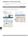
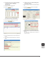
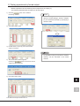
2) Checking error history
Errors occurred up to the present and the error details can be checked.
When and what kind of error occurs can be checked, useful in error analysis.
Operating procedure
1) Start C Controller setting utility.
2) Click the "Event history" tab.
2)
3) Error history and the error details are displayed.
4) To see more details of an error, double-click the
error.
3)
4)
The "Detailed event information" window appears.
5) Clicking the
or the
button will display the details of the previous or the
following error.
6) Clicking the
button will open the help
window on the error.
5)
6)
52
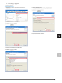
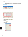
<2> Monitoring Module Status and Testing Operations
Module I/O status and buffer memory status can be checked through C Controller setting utility. I/O
status can be checked and operations can be tested at start-up and maintenance.
1) Checking module I/O status and buffer memory status
The input (X) and output (Y) status of the module and buffer memory status can be monitored.
Terminology
Buffer memory: The memory of an intelligent function module (module such as A/D conversion
module and D/A conversion module having a function other than input and
output) used to store data (such as setting values and monitored values) for
communication with a C Controller module
Operating procedure
1. Start C Controller setting utility.
1) Select [start][All Programs][MELSEC][C
Controller][C Controller setting utility].
1)
1)
C Controller setting utility starts.
2) Click the "Module monitoring" tab.
3) Click the
button.
2)
3)
The "Module monitoring" window appears.
53
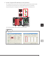
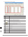
2. Check the "Module monitoring" window.
1)
2)
7)
8)
3)
4)
9)
10)
11)
5)
6)
12)
13)
14)
No.
Name
1)
Slot No.
2)
Start I/O No.
Description
Specify a slot No. to be monitored.
Displays the start I/O No. of the module mounted on the slot specified in 1).
Displays the CPU No. that controls the module mounted on the slot specified in 1).
3)
Control CPU
4)
Type
5)
button,
button
6)
54
button
When C Controller setting utility is connected to the C Controller module that serves as
a control CPU, "*" appears on the right of the CPU No.
Displays the number of I/O points and the type of a module when a module other than
a CPU module is mounted on the slot specified in 1).
Starts or stops monitoring of the C Controller module.
"*" flashes in the upper right of this button during monitoring.
Displays the "System information" window.
Monitors the input (X) of the module mounted on the slot specified in 1).
7)
Input
8)
Output
9)
Buffer memory
Monitors a buffer memory when an intelligent function module is mounted on the slot
specified in 1).
10)
Address format
Select a numeric format for "Offset".
11)
Offset
12)
Latest error
13)
Numeric format
Select a numeric format for a buffer memory or a CPU shared memory.
14)
Display format
Select a display format for a buffer memory or a CPU shared memory.
0: OFF 1: ON
Monitors the output (Y) of the module mounted on the slot specified in 1).
0: OFF 1: ON
Specify the address of a buffer memory area to be monitored.
Displays the error code of the latest error occurred in an intelligent function module.
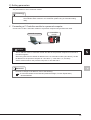
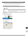
2) Testing operations by forced output
Module operations can be tested by forced output from an output (Y).
The following describes the procedure for forced output.
1) Click the
button in the "Module
monitoring" window.
Reference
1)
Double-clicking an item under "Output" will
open the "Data settings" window. Outputs
(Y) can be batch-selected by specifying a
numeric value.
2) Check the output status.
2)
3) Double-click the output (Y) from which forced
output is executed.
P oint
3)
4) The confirmation window appears.
An operation test by forced write to a buffer
memory can be executed in the same
manner.
Clicking the
button will execute forced
output from the output (Y).
4)
5) Check the output status.
5)
The LED of the output module turns on.
55
Microsoft, Windows, Windows NT, and Windows Vista are registered trademarks of Microsoft Corporation in
the United States and other countries.
Ethernet is a trademark of Xerox Corporation.
CompactFlash is a registered trademark of SanDisk Corporation.
VxWorks is a registered trademark of Wind River Systems, Inc.
Cimoperator is a registered trademark of Nippon Denno Co.,Ltd.
In-Sight is a registered trademark of Cognex Corporation.
All other company names and product names used in this guide are trademarks or registered trademarks of
their respective companies.
56