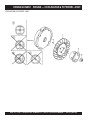
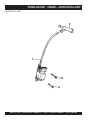
1
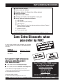
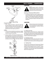
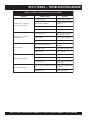
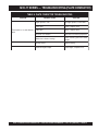
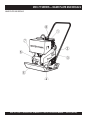
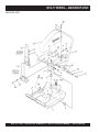
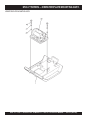
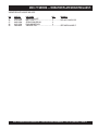
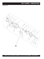
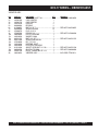
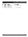
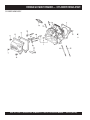
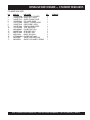
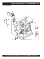
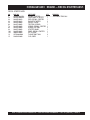
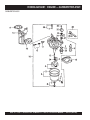
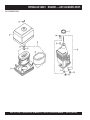
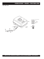
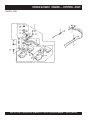
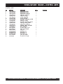
PARTS AND OPERATION MANUAL
© COPYRIGHT 2004, MULTIQUIP INC.
Plate Compactor
Model MVC-77 SERIES
Revision #2 (09/07/04)
MULTIQUIP INC..
PARTS DEPARTMENT:
18910 WILMINGTON AVE.
800-427-1244
CARSON, CALIFORNIA 90746 FAX: 800-672-7877
SERVICE DEPARTMENT/TECHNICAL ASSISTANCE:
310-537-3700
800-421-1244
800-478-1244
FAX: 310-537-3927
FAX: 310-631-5032
E-mail:[email protected] • www:multiquip.com
Atlanta • Boise • Dallas • Houston • Newark
Montreal, Canada • Manchester, UK
Rio De Janiero, Brazil • Guadalajara, Mexico
P/N 16098
l
PAGE 2 — MVC-77 SERIES PLATE COMPACTOR — PARTS & OPERATION MANUAL — REV. #2 (09/07/04)
HERE'S HOW TO GET HELP
PLEASE HAVE THE MODEL AND SERIAL NUMBER
ON-HAND WHEN CALLING
PARTS DEPARTMENT
800-427-1244 or 310-537-3700
FAX: 800-672-7877 or 310-637-3284
SERVICE DEPARTMENT/TECHNICAL ASSISTANCE
800-478-1244 or 310-537-3700
FAX: 310- 537-4259
WARRANTY DEPARTMENT
888-661-4279, or 310-661-4279
FAX: 310- 537-1173
MAIN
800-421-1244 or 310-537-3700
FAX: 310-537-3927
MVC-77 SERIES PLATE COMPACTOR — PARTS & OPERATION MANUAL — REV. #2 (09/07/04) — PAGE 3
TABLE OF CONTENTS
Here's How To Get Help ............................................ 3
Table Of Contents ..................................................... 4
Parts Ordering Procedures ....................................... 5
Safety Message Alert Symbols .............................. 6-7
Rules For Safe Operation ...................................... 8-9
Operation and Safety Decals .................................. 10
Specifications .......................................................... 11
General Information ................................................ 12
Multiquip MVC-77 Series
Plate Compactor
Components (Plate Compactor) ............................. 13
Components (Honda GX160K1 Engine) ................. 14
Inspection ........................................................... 15-16
Initial Start-Up .................................................... 17-18
Operation ................................................................ 19
Maintenance ...................................................... 20-21
Preparation For Long Term Storage ....................... 22
Troubleshooting (Engine) ................................... 23-24
Troubleshooting (Plate Compactor) ........................ 25
Explanation Of Codes In Remarks Column ............ 26
Suggested Spare Parts ........................................... 27
Name Plate and Decals ..................................... 28-29
Main Body Assembly .......................................... 30-31
Engine Pulley/Clutch Assembly.......................... 32-33
Vibrator/Plate Mounting Assembly ..................... 34-35
Vibrator Assembly .............................................. 36-37
Water Tank ......................................................... 38-39
Honda GX160K1QX2
Engine
Cylinder Head Assembly ....................................40-41
Cylinder Barrel (Recoil) Assembly .....................42-43
Crankcase Cover Assembly ...............................44-45
Crankshaft Assembly .........................................46-47
Piston/Rings Assembly.......................................48-49
Camshaft Assembly ...........................................50-51
Recoil Starter .....................................................52-53
Fan Cover Assembly ..........................................54-55
Carburetor Assembly .........................................56-57
Air Cleaner Assembly.........................................58-59
Muffler Assembly ...............................................60-61
Fuel Tank Assembly ...........................................62-63
Cooling Fan & Flywheel Assembly .....................64-65
Ignition Coil Assembly ........................................66-67
Control Assembly ...............................................68-69
Terms and Conditions Of Sale — Parts .................. 70
l
NOTE
Specification and part number
are subject to change without
notice.
PAGE 4 — MVC-77 SERIES PLATE COMPACTOR — PARTS & OPERATION MANUAL — REV. #2 (09/07/04)
PARTS ORDERING PROCEDURES
■
■
■
■
■
■
■
Dealer account number
Dealer name and address
Shipping address (if different than billing address)
Return fax number
Applicable model number
Quantity, part number and description of each part
Specify preferred method of shipment:
•
•
•
•
UPS Ground
UPS Second Day or Third Day*
UPS Next Day*
Federal Express Priority One (please provide us with your Federal
Express account number)*
•
•
Airborne Express*
Truck or parcel post
*Normally shipped the same day the order is received, if prior to 2PM west coast time.
Earn Extra Discounts when
you order by FAX!
All parts orders which include complete part numbers
and are received by fax qualify for the following extra
discounts:
Number of
line items ordered
1-9 items
Additional Discount
3%
10+ items**
5%
Get special freight allowances
when you order 10 or more
line items via FAX!**
■ UPS Ground Service at no charge for freight
■ PS Third Day Service at one-half of actual freight cost
No other allowances on freight shipped by any other carrier.
**Common nuts, bolts and washers (all items under $1.00 list price)
do not count towards the 10+ line items.
*DISCOUNTS ARE SUBJECT TO CHANGE*
ount
c
s
i
D
Fax
Extra
c USA
i
t
s
e
m
for Do
Only
s
r
e
l
a
De
Now! Direct TOLL-FREE access
to our Parts Department!
Toll-free nationwide:
800-421-1244
Toll-free FAX:
800/6-PARTS-7 • 800-672-7877
Fax order discount and UPS special programs revised June 1, 1995
MVC-77 SERIES PLATE COMPACTOR — PARTS & OPERATION MANUAL — REV. #2 (09/07/04) — PAGE 5
MVC-77 SERIES — SAFETY MESSAGE ALERT SYMBOLS
FOR YOUR SAFETY AND THE SAFETY OF OTHERS!
Safety precautions should be followed at all times when
operating this equipment. Failure to read and understand the
Safety Messages and Operating Instructions could result in
injury to yourself and others.
NOTE
This Owner's Manual has been developed to provide
complete instructions for the safe and efficient operation
of the MQ Whiteman Plate Compactor (MVC77). Refer
to the engine manufacturers instructions for data relative
to its safe operation.
Before using this vibratory roller, ensure that the
operating individual has read and understands all
instructions in this manual.
SAFETY MESSAGE ALERT SYMBOLS
The three (3) Safety Messages shown below will inform you
about potential hazards that could injure you or others. The
Safety Messages specifically address the level of exposure to
the operator, and are preceded by one of three words: DANGER,
WARNING, or CAUTION.
DANGER:
You WILL be KILLED or
SERIOUSLY injured if you do not follow
directions.
WARNING: You CAN be KILLED or
l if you do not follow
SERIOUSLY injured
HAZARD SYMBOLS
Lethal Exhaust Gases
Engine exhaust gases contain poisonous
carbon monoxide. This gas is colorless and
odorless, and can cause death if inhaled.
NEVER operate this equipment in a confined
area or enclosed structure that does not
provide ample free flow air.
Explosive Fuel
GASOLINE is extremely flammable, and its
vapors can cause an explosion if ignited. DO
NOT start the engine near spilled fuel or
combustible fluids. DO NOT fill the fuel tank
while the engine is running or hot. DO NOT
overfill tank, since spilled fuel could ignite if it
comes into contact with hot engine parts or
sparks from the ignition system. Store fuel in
approved containers, in well-ventilated areas
and away from sparks and flames. NEVER
use fuel as a cleaning agent.
Burn Hazards
Engine components can generate extreme heat.
To prevent burns, DO NOT touch these areas
while the engine is running or immediately after
operations. Never operate the engine with heat
shields or heat guards removed.
directions.
Rotating Parts
CAUTION: You CAN be injured if you
do not follow directions.
Potential hazards associated with MVC 77 Series Plate
Compactor operation will be referenced with Hazard Symbols
which appear throughout this manual, and will be referenced in
conjunction with Safety Message Alert Symbols.
NEVER operate equipment with covers, or
guards removed. Keep fingers, hands, hair and
clothing away from all moving parts to prevent
injury.
PAGE 6 — MVC-77 SERIES PLATE COMPACTOR — PARTS & OPERATION MANUAL — REV. #2 (09/07/04)
MVC-77 SERIES — SAFETY MESSAGE ALERT SYMBOLS
Accidental Starting
ALWAYS place the engine ON/OFF switch in
the OFF position when the machine is not in
use.
Respiratory Hazard
ALWAYS wear approved respiratory
protection.
Equipment Damage Messages
Sight and Hearing hazard
ALWAYS wear approved eye and hearing
protection.
Other important messages are provided throughout this manual
to help prevent damage to your trash pump, other property, or
the surrounding environment.
NOTE
This plate compactor, other property, or the
surrounding environment could be damaged
if you do not follow instructions.
MVC-77 SERIES PLATE COMPACTOR — PARTS & OPERATION MANUAL — REV. #2 (09/07/04) — PAGE 7
MVC-77 SERIES — RULES FOR SAFE OPERATION
CAUTION:
Failure to follow instructions in this manual
may lead to serious injury or even death!
This equipment is to be operated by trained
and qualified personnel only! This
equipment is for industrial use only.
The following safety guidelines should always be used when
operating the MVC-77 Series Plate Compactor:
GENERAL SAFETY
■ DO NOT operate or service this equipment before
reading this entire manual.
■ This equipment should not be operated by persons under 18
years of age.
■ NEVER operate this equipment without proper
protective clothing, shatterproof glasses, steel-toed
boots and other protective devices required by the
job.
■ NEVER operate this equipment when not feeling
well due to fatigue, illness or taking medicine.
■ NEVER operate this equipment under the
influence or drugs or alcohol.
l
■ NEVER use accessories or attachments,
which are not recommended by Multiquip for this equipment.
Damage to the equipment and/or injury to user may result.
■ ALWAYS wear proper respiratory (mask),
hearing and eye protection equipment
when operating the rammer.
■ Whenever necessary, replace nameplate, operation and
safety decals when they become difficult read.
■ ALWAYS check the machine for loosened threads or bolts
before starting.
■ Manufacture does not assume responsibility for any accident
due to equipment modifications.
■ NEVER touch the hot exhaust
manifold, muffler or cylinder. Allow
these parts to cool before servicing
engine or compactor.
■ High Temperatures – Allow the engine to cool before adding
fuel or performing service and maintenance functions. Contact
with hot components can cause serious burns.
■ The engine section of this compactor requires an adequate
free flow of cooling air. Never operate the compactor in any
enclosed or narrow area
where free flow of the air is
restricted. If the air flow is
restricted it will cause
serious damage to the
compactor or engine and
may cause injury to people.
Remember the compactor's
engine gives off DEADLY
carbon monoxide gas.
■ ALWAYS refuel in a well-ventilated area, away from sparks
and open flames.
■ ALWAYS use extreme caution when working with flammable
liquids. When refueling, stop the engine and allow it to cool.
DO NOT smoke around or near the machine. Fire or explosion
could result from fuel vapors, or if fuel is spilled on a hot
engine.
■ NEVER operate the compactor in an
explosive atmosphere or near combustible
materials. An explosion or fire could result
causing severe bodily harm or even death.
■ Topping-off to filler port is dangerous, as it
tends to spill fuel.
PAGE 8 — MVC-77 SERIES PLATE COMPACTOR — PARTS & OPERATION MANUAL — REV. #2 (09/07/04)
MVC-77 SERIES — RULES FOR SAFE OPERATION
■ NEVER Run engine without air filter. Severe engine may
occur.
■ ALWAYS service air cleaner frequently to prevent carburetor
malfunction.
■ ALWAYS be sure the operator is familiar with proper safety
precautions and operations techniques before using
compactor.
■ ALWAYS store equipment properly when it is not being used.
Equipment should be stored in a clean, dry location out of the
reach of children.
■ NEVER use accessories or attachments, which are not
■ NEVER use accessories or attachments, which are not
recommended by Multiquip for this equipment. Damage to
the equipment and/or injury to user may result.
■ NEVER Run engine without air cleaner. Severe engine
damage may occur.
■ ALWAYS read, understand, and follow procedures in
Operator’s Manual before attempting to operate equipment.
■ ALWAYS be sure the operator is familiar with proper safety
precautions and operations techniques before using pump.
■ ALWAYS store equipment properly when it is not being used.
Equipment should be stored in a clean, dry location out of the
reach of children.
■ Refer to the HONDA or ROBIN Engine Owner's Manual for
engine technical questions or information.
Loading and Unloading (Crane)
■ Before lifting, make sure that machine parts (hook and
vibration insulator) are not damaged and screws are not
loosened or lost.
Transporting
■ ALWAYS shutdown engine before transporting.
■ Tighten fuel tank cap securely and close fuel cock to prevent
fuel from spilling.
■ Drain fuel when transporting compactor over long distances
or bad roads.
■ ALWAYS tie-down the compactor during transportation by
securing the compactor's guard frame with rope.
Emergencies
■ ALWAYS know the location of the nearest fire extinguisher
and first aid kit. Know the location of the nearest telephone.
Also know the phone numbers of the nearest ambulance,
doctor and fire department. This information will be
invaluable in the case of an emergency.
Maintenance Safety
■ NEVER lubricate components or attempt service on a running
machine.
■ ALWAYS allow the machine a proper amount of time to cool
before servicing.
■ Keep the machinery in proper running condition.
■ Fix damage to the machine immediately and always replace
broken parts.
■ Dispose of hazardous waste properly. Examples of potentially
hazardous waste are used motor oil, fuel and fuel filters.
■ DO NOT use plastic containers to dispose of hazardous
waste.
■ DO NOT pour waste, oil or fuel directly onto the ground,
down a drain or into any water source
■ ALWAYS make sure crane or lifting device has been properly
secured to the hook of guard frame on compactor.
■ NEVER lift the machine while the engine is running.
■ Use adequate lifting cable (wire or rope) of sufficient strength.
■ Use one point suspension hook and lift straight upwards.
■ NEVER allow any person or animal to stand underneath the
machine while lifting.
■ Try not to lift machine to unnecessary heights.
MVC-77 SERIES PLATE COMPACTOR — PARTS & OPERATION MANUAL — REV. #2 (09/07/04) — PAGE 9
MVC-77 SERIES — OPERATION AND SAFETY DECALS
Machine Safety Decals
The MVC-77 Series Reversible Plate Compactor is equipped with a number of safety decals. These decals are provided for operator
safety and maintenance information. The illustration below shows these decals as they appear on the machine. Should any of these
decals become unreadable, replacements can be obtained from your dealer.
l
PAGE 10 — MVC-77 SERIES PLATE COMPACTOR — PARTS & OPERATION MANUAL — REV. #2 (09/07/04)
MVC-77 SERIES — SPECIFICATIONS
TABLE 1. COMPACTOR SPECIFICATIONS
Model
MVC-77, S, H and SH
Centrifugal Force
3,350 lbs. (1520 kg)
Number of Vibrations
5,800 vibrations/min
Traveling Speed
82 meters/min (82 ft./min)
Plate Size (LxW)
.49 x .57 cm
(17 x 22 in.)
166 lbs. (75.0 kg.)
195 lbs. ( 88.4 kg.)
Operating Weight
Operating Weight (Water Tank)
Water Tank Capacity
13.7 qt.
6970 sq. ft./hr.
Max. Area Of Compaction
TABLE 2. ENGINE SPECIFICATIONSS
Engine Make
HONDA
ROBIN
Engine Model
GX160K1QX2
EH172YD4020
Engine Type
OHV Gasoline Engine
OHV Gasoline Engine
1
1
Bore/Stroke
68 MM X 45 MM
(2.70 IN X 1.8 IN)
67 MM X 49 MM
(2.64 IN X 1.93 IN)
Displacement
163 cc (9.9 cu. in)
172 cc (10.50 cu. in)
Maximum Output
5.5 H.P./3,600 rpm
6.0 H.P./4,000 rpm
See Table 3
See Table 3
1.3 pints/0.6 liters
1.3 pints/0.6 liters
Unleaded
Unleaded
3.8 qt./3.6 liters
3.8 qt./3.6 liters
Dry Weight
15 kg/33 lbs.
16 kg/35 lbs.
Star ting Method
Recoil Star t
Recoil Star t
Number Of Cylinders
Oil Grade
Oil Capacity
Fuel Type
Fuel Tank Capacity
MVC-77 SERIES PLATE COMPACTOR — PARTS & OPERATION MANUAL — REV. #2 (09/07/04) — PAGE 11
MVC-77 SERIES — GENERAL INFORMATION
Definition of Plate Compactor
Frequency/Speed
The Mikasa MVC-77 Series is a walk behind, plate compactor
designed for the compaction of sand, mixed soils and asphalt.
This plate compactor is a powerful compacting tool capable of
applying a tremendous force in consecutive high frequency
vibrations to a soil surface. Its applications include compacting
for road, embankments and reservoirs as well as backfilling for
gas pipelines, water pipelines and cable installation work.
The compactor's vibrating plate has a frequency range between
5,800 vpm (vibrations per minute). The forward and reverse travel
speed of the compactor is approximately 23 meters/minute (75
ft./minute).
Vibratory Plates
The vibratory plates of the compactor produce low amplitude
high frequency vibrations, designed to compact granular soils
and asphalt.
The resulting vibrations cause forward motion. The engine and
handle are vibration isolated from the vibrating plate.
Engine
The Mikasa MVC-77 Series Plate Compactor is equipped with
either a Honda or Robin air cooled, 4-cycle gasoline engine.
The engine drives an eccentric weight at a high speed to develop
a compaction force.
Controls
Before starting the MVC-77 Series Plate Compactor identify and
understand the function of the controls and components as
indicated on page 13 (Figure 1).
l
PAGE 12 — MVC-77 SERIES PLATE COMPACTOR — PARTS & OPERATION MANUAL — REV. #2 (09/07/04)
MVC-77 SERIES — COMPONENTS (PLATE COMPACTOR)
4
3
2
1
5
11
WATER
TA
NK
9
10
6
sa
ka
Mi
Mikas
a
8
7
Figure 1. MVC-77 Series Plate Compactor Components
Figures 1 and 2 shows the location of the components and
general maintenance parts. The function of each component is
described below:
6.
Belt Cover – Remove this cover to gain acess to the Vbelts. NEVER run the compactor without the V-belt cover. If
the V-belt cover is not installed, the possibility exist that
your hand may get caught between the V-belt and clutch,
thus causing serious injury and bodily harm.
1.
Water Tank Cap – Remove this cap to add water to the
water tank.
2.
Fuel Tank Cap – Remove this cap to add fuel.
7.
3.
Lifting Bale – When lifting of the compactor is required
either by forklift, crane etc., tie rope or chain around this
lifting point.
Vibrating Plate – A flat, open plate made of durable cast
iron construction used in the compacting of soil.
8.
Vibration Case – Encloses the eccentric, gears and
counter weights.
4.
Handle Bar – When operating the compactor use this
handle bar to manuever the compactor.
9.
Water Tube (Sprinkler) – Supplies water to the soil via a
splash plate.
5.
Gasoline Engine – This plate compactor uses a HONDA
GX160K1QX2 or ROBIN EH172YD4020 engine. Refer to
the HONDA or ROBIN owners manual for engine
information and related topics.
10. Water Shut-Off Valve – Turn this valve downward to let
water flow from the water tank to the water tube.
11. Water Tank – Holds 13.7 quarts of water, removable no
tools required.
MVC-77 SERIES PLATE COMPACTOR — PARTS & OPERATION MANUAL — REV. #2 (09/07/04) — PAGE 13
MVC-77 SERIES — COMPONENTS (HONDA GX160K1QX2 ENGINE)
NOTE
This manual is showing an HONDA
engine, component locations may vary
with other engines.
Figure 2. Engine Controls & Components
5.
Fuel Valve Lever – OPEN to let fuel flow, CLOSE to stop
the flow of fuel.
6.
Choke Lever – Used in the starting of a cold engine, or in
cold weather conditions. The choke enriches the fuel
mixture.
7.
Air Cleaner – Prevents dirt and other debris from entering
the fuel system. Remove wing-nut on top of air filter
cannister to gain access to filter element.
INITIAL SERVICING
The engine (Figure 2) must be checked for proper lubrication and
filled with fuel prior to operation. Refer to the manufacturers Engine
manual for instructions & details of operation and servicing.
1.
Fuel Filler Cap – Remove this cap to add unleaded
gasoline to the fuel tank. Make sure cap is tightened
securely. DO NOT over fill.
NOTE
Operating the engine without an air filter,
with a damaged air filter, or a filter in need of
replacement will allow dirt to enter the
engine, causing rapid engine wear.
WARNING
WARNING
Adding fuel to the tank
l should be accomplished only
when the engine is stopped and has had an
opportunity to cool down. In the event of a fuel spill,
DO NOT attempt to start the engine until the fuel residue has been
completely wiped up, and the area surrounding the engine is dry.
2.
Throttle Lever – Used to adjust engine RPM speed (lever
advanced forward SLOW, lever back toward operator
FAST).
3.
Engine ON/OFF Switch – ON position permits engine
starting, OFF position stops engine operations.
4.
Recoil Starter (pull rope) – Manual-starting method. Pull
the starter grip until resistance is felt, then pull briskly and
smoothly.
8.
Spark Plug – Provides spark to the ignition system. Set
spark plug gap to 0.6 - 0.7 mm (0.028 - 0.031 inch) for
HONDA engine, and 0.5 - 0.6 mm (0.020 - 0.024 inch) for
ROBIN engine. Clean spark plug once a week.
9.
Muffler – Used to reduce noise and emissions.
WARNING
Engine components can generate extreme heat.
To prevent burns, DO NOT touch these areas
while the engine is running or immediately after operating. NEVER
operate the engine with the muffler removed.
10. Fuel Tank – Holds unleaded gasoline. For additional
information refer to engine owner's manual.
PAGE 14 — MVC-77 SERIES PLATE COMPACTOR — PARTS & OPERATION MANUAL — REV. #2 (09/07/04)
MVC-77 SERIES — INSPECTION
Before Starting
1. Read safety instructions at the beginning of manual.
2. Clean the compactor, removing dirt and dust. Particularly, the
bottom of the plate, engine cooling air inlet, carburetor and
air cleaner.
3. Check the air filter for dirt and dust. If the air filter is dirty, blow
through the air filter cartridge from the inside, moving a jet of
dry compressed air up and down until all dust is removed.
Otherwise replace air filter with a new one.
4. Check carburetor for external dirt and dust. Clean with dry
compressed air.
NOTE
The Oil Alert system will automatically
stop the engine before the engine falls
below safe limits. Always be sure to check
the engine oil level prior to starting the
engine.
Table 3. Oil Type
Season
Temperature
Oil Type
Summer
25°C or Higher
SAE 10W-30
Spring/Fall
25°C~10°C
SAE 10W-30/20
Winter
0°C or Lower
SAE 10W-10
5. Check fastening nuts and bolts for tightness. Loosened
screws or bolts due to vibration, could lead to unexpected
accident.
Gasoline Check
Engine Oil Check
1. Remove the gasoline cap located on top of fuel tank.
1. To check the engine oil level, place the plate compactor on
secure level ground with the engine stopped.
2. Visually inspect to see if fuel level is low. If fuel is low, replenish
with unleaded fuel.
2. Remove the filler cap/dipstick from the engine oil filler hole
(Figure 3) and wipe it clean.
3. When refueling, be sure to use a strainer for filtration. DO
NOT top-off fuel. Wipe up any spilled fuel.
Vibrator Oil Check
1. Place the MVC-77 Series plate compactor horizontally on a
flat surface. Make sure the compactor is level when checking
the oil in the vibrator assembly.
2. Check vibrator oil level by removing the plug (vibrator oil gauge)
as shown in Figure 5. The oil level should be up to the oil plug.
The vibrator holds 140 cc (approximately 1 pint).IMPORTANT,
if oil is required, replace using only SAE 10W-30 motor oil.
Figure 3. Engine Oil Dipstick
3. Insert and remove the dipstick without screwing it into the filler
neck. Check the oil level shown on the dipstick.
4. If the oil level is low (Figure 4), fill to the edge of the oil filler
hole with the recommended oil type (Table 3). Maximum oil
capacity is 400 cc.
UPPER LIMIT
LOWER LIMIT
Figure 5. Vibrator Oil Plug
Figure 4. Engine Oil Dipstick
MVC-77 SERIES PLATE COMPACTOR — PARTS & OPERATION MANUAL — REV. #2 (09/07/04) — PAGE 15
MVC-77 SERIES — INSPECTION
2. The V-belt tension is proper if the V-belt bends 10 to 15 mm
(Figure 8) when depressed with finger at midway between
the clutch and vibration pulley shafts.
V-Belt Check
CAUTION:
NEVER attempt to check the V-belt with the
engine running. Severe injury can occur of
your hand (Figure 6) gets caught between the
V-belt and the clutch. Always use safety gloves.
CLUTCH
PULLEY
Figure 8. V-Belt Tension
VIBRATOR
PULLEY
Figure 6. V-Belt Hazard
3. A loose V-belt will decrease the power transmission output,
causing reduced compaction and premature wear of the
belt.
4. If the V-belt becomes worn or loose, replace it by using Vbelt part number 070503350
1. To check the V-belt tension, remove the three bolts that
secure the belt cover to the frame as shown in Figure 7.
l
Figure 7. V-Belt Cover Removal
PAGE 16 — MVC-77 SERIES PLATE COMPACTOR — PARTS & OPERATION MANUAL — REV. #2 (09/07/04)
MVC-77 SERIES — INITIAL START-UP
CAUTION:
DO NOT attempt to run the compactor untilDthe
Safety and Initial Start-up sections have been
read,
NOTE
The CLOSED position of the choke lever enriches
the fuel mixture for starting a COLD engine. The
OPEN position provides the correct fuel mixture
for normal operation after starting, and for
restarting a warm engine.
1. Place the fuel valve lever (Figure 9) in the "ON" position.
4. Place the throttle lever (Figure 12) halfway between fast
and slow.
Figure 9. Fuel Valve Lever
2. Place the Engine ON/OFF switch (Figure 10) in the "ON"
position.
Figure 12. Throttle Lever
5. Grasp the starter grip (Figure 13) and slowly pull it out. The
resistance becomes the hardest at a certain position, corresponding the compression point. Rewind the rope a little from
that point and pull out sharply.
CAUTION:
z DO NOT pull the starter rope all the way
to the end.
Figure 10. Engine ON/Off Switch
3. Place the Choke Lever (Figure 11) in the "OPEN" position.
z DO NOT release the starter rope after
pulling. Allow it to rewind as soon as
possible.
Nnnn
Figure 11. Choke Lever
Figure 13. Starter Grip
MVC-77 SERIES PLATE COMPACTOR — PARTS & OPERATION MANUAL — REV. #2 (09/07/04) — PAGE 17
MVC-77 SERIES — INITIAL START-UP
6. If the engine has started, slowly return the choke lever
(Figure 11) to the CLOSED position. If the engine has not
started repeat steps 1 through 5.
7. Before the compactor is put into operation run the engine for
3-5 minutes.
8. Check for abnormal engine noises or fuel leaks.
Stopping the Engine
CAUTION:
z NEVER stop the engine suddenly while
working at high speeds.
1. Place the throttle lever (Figure 12) in slow position, and
listen for the engine speed to decrease.
2. Place the Engine ON/OFF switch (Figure 11) in the "OFF
" position.
3. Place the fuel valve lever (Figure 9) in the "OFF" position.
l
PAGE 18 — MVC-77 SERIES PLATE COMPACTOR — PARTS & OPERATION MANUAL — REV. #2 (09/07/04)
MVC-77 SERIES — OPERATION
Operation
CAUTION:
Make sure to follow all safety rules referenced
in the safety section of this manual before operating compactor. Keep work area clear of debris
and other objects that could cause damage to
the compactor or bodily injury.
1. Once the engine has started, move the engine throttle lever
quickly to the fast position.
2. With the throttle lever in the fast position, the engine speed
should be around 2,300 RPM, therefore engaging the centrifugal clutch.
7. Compactor traveling speed may drop on soils which contain
clay, however there may be cases where traveling speed
drops because the compaction plate does not leave the
ground surface easily due to the composition of the soil. To
rectify this problem do the following:
z Check the bottom plate to see if clay or
equivalent material has been lodge in the
plate mechanism. If so, wash with water and
remove.
z Remember the compactor does not work as
efficiently on clay or soils that have a high
moisture content level.
z If the soil has a high moisture level, dry soil
to appropriate moisture content level or carry
out compaction twice.
NOTE
Always move the throttle lever quickly without
hesitation, because increasing the engine speed
slowly causes the clutch to slip.
5. Firmly gasp the compactor's handle bar with both hands , the
compactor will begin moving forward.
6. Slowly walk behind the compactor and be on the lookout for
any large objects or foreign matter that might cause damage
to the compactor or bodily injury.
MVC-77 SERIES PLATE COMPACTOR — PARTS & OPERATION MANUAL — REV. #2 (09/07/04) — PAGE 19
MVC-77 SERIES — MAINTENANCE
CAUTION:
CAUTION:
These inspection intervals are for operation
under normal conditions. Adjust your inspection
intervals based on the number hours plate
compactor is in use, and particular working
conditions.
Inspection and other services should always
be carried out on hard and level ground with
the engine shutdown.
Inspection and Maintenance Service Tables.
1. To make sure your plate compactor is always in good
working condition before using, carry out the maintenance
inspection in accordance with Tables 4 through 6.
TABLE 4. MACHINE INSPECTION
Item
Hours of Operation
Remarks
(Starting check)
Every 8 hours (every
day)
Loosened or lost
screws
Every 8 hours (every
day)
Damage of any part
Every 8 hours (every
day)
Function of controlling
system part
Every 8 hours (every
day)
Vibrator oil check
Every 100 hours
See page 19.
Vibrator oil
replacement
Every 200 hours
See page 19.
V-belt (clutch) check
Every 200 hour
See page 19.
CAUTION:
Fuel piping and connections should be
replaced every 2 years.
Daily Service
z Check for leakage of fuel or oil.
z Remove soil and clean the bottom of compaction plate.
z Check engine oil, see page 13.
z Check for loose screws including tightness. See Table 6
below (tightening torque ), for retightening:
TABLE 6.
TIGHTENING TORQUE (in. kg/cm) Diameter
Material 6mm
8mm
10mm 12mm 14mm 16mm 18mm 20mm
4T
70
150
300
500
750
1 ,1 0 0
1 ,4 0 0
2,000
6-8T
100
250
500
800
1 ,3 0 0
2,000
2 ,7 0 0
3,800
11T
150
400
800
1,200
2,000
2,900
4 ,2 0 0
5,600
*
100 (6mm) 300 ~ 350 (8mm) 650 ~ 700 (10mm)
* (In case counter-par t is of aluminum)
(Threads in use with this machine are all right handed)
l
TABLE 5. ENGINE CHECK
(For details, see separate Engine Manual)
Item
Material and quality of material is marked on each bolt,
and screw.
Engine Oil Replacement:
Hours of Operation
Leakage of oil or fuel
Every 8 hours (every day)
Tightness of fastening threads
Every 8 hours (every day)
Engine oil check and
replenishment
Every 8 hours (every
day)(Replenish to specified max.
level)
Engine oil replenishment
At first 20 hours, then every 100
hours
Air cleaner cleaning
Every 50 hours
1. Replace engine oil, in first 20 hours of operation and every
100 hours afterwards.
2. Oil may be drained more easily when it is warm after
operation (For more details, see separate HONDA or ROBIN
Owner's Manual).
3. When changing the engine oil, thenold oil can be drained
by removing the oil filler cap, and un-screwing the engine
oil drain plug located at the base of the engine.
4. Remember to refill engine crankcase with the recommended
type of oil as listed in Table 3.
PAGE 20 — MVC-77 SERIES PLATE COMPACTOR — PARTS & OPERATION MANUAL — REV. #2 (09/07/04)
MVC-77 SERIES — MAINTENANCE
CAUTION:
NEVER attempt to check the V-belt with the
engine running. Severe injury can occur if your
hand (Figure 6) gets caught between the V-belt
and the clutch. Always use safety gloves.
Checking and Replacing the V-Belt and Clutch
1. After 200 hours of operation, remove the upper belt cover to
check the V-belt tension. Tension is proper if the belt bends
about 10 mm when depressed strongly with finger between
shafts. Loose or worn V-belts reduces power transmission
efficiency, causing weak compaction and reduces the life of
the belt itself.
Figure 14. Engine Oil Plug
Changing Vibrator Oil
1. When changing the vibrator oil, remove the drain plug
located at the bottom- right of the vibrator (Figure 5), and
simply tip the compactor to drain the oil. Note that the oil will
drain more easily while it is hot. Remember to use only
10W-30 motor oil when replaceing vibrator oil.
Air Filter
1. The air filter element should be cleaned because a clogged
air cleaner can cause poor engine starting, lack of power
and shorten engine life substantially.
2. To clean or replace air filter loosen the wing nut on the air
filter housing (Figure 15), remove the cover and take out air
filter cartridge. If only cleaning of the air filter is desired blow
through the air filter cartridge from the inside, moving a jet of
dry compressed air up and down until all dust is removed.
CAUTION:
Whenever the compactor's vibration becomes
weak or lost during normal operation regardless of operation hours, check the V-belt and
clutch immediately.
z Replacing the V-belt
Remove the upper and lower belt covers. Engage an offset
wrench (13 mm) or the like to vibrator pulley (lower) fastening
bolt. Engage waste cloth or the like at midway of V-belt on the left
side and while pulling it back strongly, rotate the offset wrench
clockwise so that the V-belt will come off.
z Reinstalling the V-belt
Engage V-belt to lower vibrator pulley and push the V-belt to left
side of upper clutch and, in the same manner as in removal,
rotate offset wrench clockwise so that the V-belt goes back on.
z Checking Clutch
Check the clutch simultaneously with V-belt checking. With belt
removed, check outer drum of the clutch for seizure and "V"
groove for wear or damage with your eyes. Clean the "V" groove
as necessary. Wear of lining or shoe should be checked with
running check. If the shoe is worn, power transmission becomes
deficient and slipping will result.
Figure 15. Air Filter
MVC-77 SERIES PLATE COMPACTOR — PARTS & OPERATION MANUAL — REV. #2 (09/07/04) — PAGE 21
MVC-77 SERIES — PREPARATION FOR LONG -TERM STORAGE
Pump Storage
For storage of the pump for over 30 days, the following is
required:
z Drain the fuel tank completely.
z Run the engine until the fuel in the injection system is
completely consumed.
z Completely drain the oil from the engine crankcase and
follow procedures described in the HONDA engine
Owner's Manual for engine storage.
z Completely drain the compactor's hydraulic oil from the
vibrating case.
z Clean entire plate compactor, especially the bottom plate
removing all dirt and foreign matter.
z Cover plate compactor and engine with plastic covering
or equivalent and store in a clean, dry place.
l
PAGE 22 — MVC-77 SERIES PLATE COMPACTOR — PARTS & OPERATION MANUAL — REV. #2 (09/07/04)
MVC-77 SERIES — TROUBLESHOOTING (ENGINE)
TABLE 7. ENGINE TROUBLESHOOTING
SYMPTON
Difficult to star t, "fuel is available, but no
SPARK at spark plug".
POSSIBLE CAUSE
Spark plug bridging?
Check gap, insulation or
replace spark plug.
Carbon deposit on spark plug?
Clean or replace spark plug.
Shor t circuit due to deficient spark plug
insulation?
Check spark plug insulation,
replace if worn.
Improper spark plug gap?
Set to proper gap.
ON/OFF switch is shor ted?
Check switch wiring, replace
switch.
Ignition coil defective?
Replace ignition coil.
Difficult to star t, "fuel is available, and Improper spark gap, points dir try?
SPARK is present at the spark plug".
Difficult to star t, "fuel is available, spark
is present and compression is normal"
Difficult to star t, "fuel is available, spark
is present and compression is low"
No fuel present at carburetor.
SOLUTION
Set correct spark gap and
clean points.
Condenser insulation worn or shor t
circuiting?
Replace condenser.
Spark plug wire broken or shor t circuiting?
R e p l a c e d e fe c t i ve s p a r k p l u g
wiring.
Wrong fuel type?
Flush fuel system, and replace
with correct type of fuel.
Water or dust in fuel system?
Flush fuel system.
Air cleaner dir ty?
Clean or replace air cleaner.
Suction/exhaust valve stuck or protruded?
Re-seat valves.
Piston ring and/or cylinder worn?
Replace piston rings and or
piston.
Cylinder head and/or spark plug not
tightened properly?
Torque cylinder head bolts and
spark plug.
Head gasket and/or spark plug gasket
damaged?
Replace head and spar k plug
gaskets.
Fuel not available in fuel tank?
Fill with correct type of fuel.
Fuel cock does not open properly?
Apply lubr icant to loosen fuel
cock lever, replace if necessary.
Fuel filter clogged?
Replace fuel filter.
Fuel tank cap breather hole clogged?
Clean or replace fuel tank cap.
Air in fuel line?
Bleed fuel line.
MVC-77 SERIES PLATE COMPACTOR — PARTS & OPERATION MANUAL — REV. #2 (09/07/04) — PAGE 23
MVC-77 SERIES — TROUBLESHOOTING (ENGINE)
TABLE 7. ENGINE TROUBLESHOOTING (CONTINUED)
SYMPTON
"Weak in power" compression is
proper and does not misfire.
POSSIBLE CAUSE
SOLUTION
Air cleaner not clean?
Clean or replace air cleaner
Improper level in carburetor?
Check float adjustment, re-build
carbureator.
Defective Spark plug?
Clean or replace spark plug.
Defective Spark plug?
"Weak in power" compression is
proper but misfires.
Engine overheats.
Rotational speed fluctuates.
Recoil star ter malfunction.
Water in fuel system?
Flush fuel system, and replace
with correct type of fuel.
Dir ty spark plug?
Clean or replace spark plug.
Ignition coil defective?
Replace ignition coil.
Spark plug heat value improper?
Replace with correct type of
spark plug.
Correct type of fuel?
Replace with correct type of fuel
Cooling fins dir ty?
Clean cooling fins.
Governor adjusted correctly?
Adjust governor.
Governor spring defective?
Replace governor spring.
Fuel flow restricted?
C h e c k e n t i r e f u e l s y s t e m fo r
leaks or clogs.
Recoil mechanism clogged with dust and
dir t?
Clean recoil assembly with soap
and water.
Sprial spring loose?
Replace sprial spring.
l
PAGE 24 — MVC-77 SERIES PLATE COMPACTOR — PARTS & OPERATION MANUAL — REV. #2 (09/07/04)
MVC-77 SERIES — TROUBLESHOOTING (PLATE COMPACTOR)
TABLE 8. PLATE COMPACTOR TROUBLESHOOTING
SYMPTON
POSSIBLE CAUSE
SOLUTION
Engine speed too low?
Set engine speed to correct RPM.
Clutch slips?
Check or replace clutch.
Travel speed too low, and vibration is V-belt slips?
weak.
Excessive oil in vibrator?
Adjust or replace V-belt.
Drain excess oil and fill to proper level.
Malfunction in vibrator housing?
Check eccentric, gears and counter
weights.
Bearing Failure?
Replace Bearing
Insufficient engine output?
Check engine, compression etc.
MVC-77 SERIES PLATE COMPACTOR — PARTS & OPERATION MANUAL — REV. #2 (09/07/04) — PAGE 25
MVC-77 SERIES — EXPLANATION OF CODE IN REMARKS COLUMN
How to read the marks and remarks used in this parts book.
Section 1: Items Found In the “Remarks” Column
Serial Numbers-Where indicated, this indicates a serial
number range (inclusive) where a particular part is used.
Model Number-Where indicated, this shows that the
corresponding part is utilized only with this specific model
number or model number variant.
Section 2: Items Found In the “Items Number” Column
All parts with same symbol in the number column:
*, #, +, %, or ■, belong to the same assembly or kit.
Note: If more than one of the same reference number is
listed, the last one listed indicates newest (or latest) part
available.
NOTE
If more than one of the same reference number is
listed, the last one listed indicates newest (or latest)
part available.
l
NOTE
The contents of this catalog are
subject to change without notice.
PAGE 26 — MVC-77 SERIES PLATE COMPACTOR — PARTS & OPERATION MANUAL — REV. #2 (09/07/04)
MVC-77 SERIES — SUGGESTED SPARE PARTS
MVC-77 Series1 TO 5 UNITS WITH HONDA
GX160K1QX2 ENGINE
1 to 3 Units
Qty.
P/N
Description
3 ............ 070503350 ............ V-BELT
1 ............ 060403060 ............ OIL SEAL, VIBRATING
2 ............ 050101000 ............ O-RING (FOR HANDLE)
3 ............ 9807956841 .......... SPARK PLUG (HONDA)
1 ............ 28462ZH8003 ....... ROPE, RECOIL STARTER (HONDA)
1 ............ 36100ZE1015 ....... SWITCH ASSY, ENGINE STOP (HONDA)
3 ............ 17210ZE1505 ....... ELEMENT, A/C (HONDA)
1 ............ 17620ZH7023 ....... CAP, FUEL TANK (HONDA)
1 ............ 17672ZE2W01 ...... FUEL FILTER, FUEL TANK (HONDA)
4 ............ 930405011 ............ SHOCK ABSORBER
MVC-77 SERIES PLATE COMPACTOR — PARTS & OPERATION MANUAL — REV. #2 (09/07/04) — PAGE 27
MVC-77 SERIES — NAME PLATE AND DECALS
NAME PLATE AND DECALS
l
PAGE 28 — MVC-77 SERIES PLATE COMPACTOR — PARTS & OPERATION MANUAL — REV. #2 (09/07/04)
MVC-77 SERIES — NAME PLATE AND DECALS
NAME PLATE AND DECALS
NO
PART NO
PART NAME
1
2
3
4
5
6
7
8
920203290
920203060
920201580
920106460
920201950
DECAL:
DECAL:
DECAL:
DECAL:
DECAL:
PLATE:
DECAL:
DECAL:
13118
920203330
CAUTION
CAUTION (START ENG/VIBR)
MQ LOGO
MIKISA LOGO (NAME)
MOTOR OIL
SERIAL NO./MVC-MQ
POWDER COATED
EAR PROTECTION LABEL
QTY.
1
1
2
1
1
1
1
1
REMARKS
DSC01
NPA-306
NPA-158
NPA-507
NPA-195
CONTACT MQ SERVICE DEPT. W/MODEL & S/N
NPA-333
SEE DECAL ILLUSTRATIONS ON PAGE 10.
MVC-77 SERIES PLATE COMPACTOR — PARTS & OPERATION MANUAL — REV. #2 (09/07/04) — PAGE 29
MVC-77 SERIES — MAIN BODY ASSY.
MAIN BODY ASSY.
l
PAGE 30 — MVC-77 SERIES PLATE COMPACTOR — PARTS & OPERATION MANUAL — REV. #2 (09/07/04)
MVC-77 SERIES — MAIN BODY ASSY.
MAIN BODY ASSY.
NO
PART NO
PART NAME
1
2
3
4
4
5
6
7
8
8
9
11
12
13
15
15
16
16
17
18
26
27
28
31
32
33
34
36
45
60
61
62
63
72
408105330
930405011
031110160
408105320
408109390
939010010
020310080
030210250
959404350
959404350
031108160
011008040
011208045
030208200
408420810
408420810
408207200
408209910
050200160
020108060
408404240
408104800
014208020
408206161
952402281
952403450
0105091025
408010030
408010080
001221235
030212300
011208045
030208200
920103260
VIBRATING PLATE, 430/77
1
SHOCK ABSORBER MED-50/S
4
PLAIN WASHER M10
4
BASE .......................................................... 1 ............. ROBIN
BASE .......................................................... 1 ............. HONDA
SHOCK ABSORBER, STOPPER 45
1
NUT M10
9
SPRING WASHER M10
11
SPRING ...................................................... 1 ............. REPLACES 401010020
EARTH WIRE
1
PLAIN WASHER M8
9
BOLT 8X40 T .............................................. 4 ............. REPLACES 001220840
BOLT 8X45 T .............................................. 1 ............. REPLACES 001220845
SPRING WASHER 8M
8
ENGINE NUT ............................................. 1 ............. ROBIN
ENGINE NUT ............................................. 2 ............. HONDA
HOOK ......................................................... 1 ............. ROBIN
HOOK ......................................................... 1 ............. HONDA
O-RING
2
NUT M8, H=5
1
REPLACES 020408050
STOPPER
1
BELT COVER
1
BOLT 8X20 T .............................................. 4 ............. REPLACES 001220820
HANDLE
1
WASHER 21363 (DELRIN)
4
WASHER 11X36X4.5 ................................. 2 ............. REPLACES 952400220
BOLT 10X25 T ............................................ 2 ............. REPLACES 001221025
PLUG 1/4
1
HOSE JOINT 1/4X10D
1
BOLT 12X35 T ............................................ 2 ............. REPLACES 001221235 HONDA
SW M12 ...................................................... 2 ............. HONDA
BOLT 8X45 T .............................................. 2 ............. ROBIN
SPRING WASHER M8 ............................... 2 ............. REPLACES 001220845 ROBIN
PLATE, SERIAL .......................................... 1 ............. CONTACT MULTIQUIP SERVICE DEPT
..................................................................................... WITH MODEL AND SERIAL NUMBER
QTY.
REMARKS
MVC-77 SERIES PLATE COMPACTOR — PARTS & OPERATION MANUAL — REV. #2 (09/07/04) — PAGE 31
MVC-77 SERIES — ENGINE PULLEY/CLUTCH ASSY.
ENGINE PULLEY/CLUTCH ASSY.
l
PAGE 32 — MVC-77 SERIES PLATE COMPACTOR — PARTS & OPERATION MANUAL — REV. #2 (09/07/04)
MVC-77 SERIES — ENGINE PULLEY/CLUTCH ASSY.
ENGINE PULLEY/CLUTCH ASSY.
NO
PART NO
10
10
10
19
19
20
21
22
23
23
24
25
29
30
50
51
52
53
54
55
56
57
58
59
76
78
79
80
81
82
EH172YD4020 ENGINE ASSY. (ROBIN) ............................ 1 ............. REPLACES 911202046
ENGINE ASSY. (HONDA) .......................... 1 ............. GX140Q1B5 NO LONGER AVAILABLE
GX160K1QX2 ENGINE ASSY. (HONDA) .......................... 1 ............. REPLACES 912216002
408420830
CLUTCH SPACER ..................................... 1 ............. ROBIN
408434570
SPACER 20X25X8.4/77H .......................... 1 ............. HONDA
408910020
CLUTCH ASSSY ........................................ 1 ............. REPLACES 16053
408412320
KEY 4.78X4.78X20
1
952403630
WASHER 9X30X3 ...................................... 1 ............. HONDA
009110003
BOLT 5/16-24 UNF-35MM (HONDA) ........ 1 ............. REPLACES 402010150
404010060
BOLT 5/16-24UNF-20MM .......................... 1 ............. HONDA
030208200
SPRING WASHER M8 ............................... 1 ............. HONDA
070503350
V-BELT ( 3VX-335)
1
408010060
SOCKET HEAD BOLT 3/8X32 .................. 1 ............. ROBIN
031110160
WASHER 11253 ......................................... 1 ............. REPLACES 952401440 (ROBIN)
943010010
PULLEY DRUM
1
943020010
CLUTCH SHOE
2
943050010
CLUTCH BOSS/D; 19.05
1
943040010
BEARING COLLAR/D; 19.05
1
JISB2804C25 STOP RING ............................................... 1 ............. REPLACES 080200250
943050020
ARM PIN
2
080300090
STOP RING
4
943030010
CLUTCH SPRING
2
080100520
STOP RING
1
046006250
BEARING (6205 DDU) ............................... 1 ............. REPLACES 046006250
408910020
CLUTCH ROTOR ...................................... 1 ............. REPLACES 16093
16095
BEARING 1.1/8” ID X 2.1/8” OD
1
408910020
DRUM 4.5/8” (INCLUDES ITEMS 77 & 78) 1 ............. REPLACES 16096
EM926029
RETAINING RING 1.1/8” DIA
1
16086
CLUTCH RETAINER
1
2638
FHSC CAP SCREW 5/16-24 X1
1
PART NAME
QTY.
REMARKS
MVC-77 SERIES PLATE COMPACTOR — PARTS & OPERATION MANUAL — REV. #2 (09/07/04) — PAGE 33
MVC-77 SERIES — VIBRATOR/PLATE MOUNTING ASSY.
VIBRATOR/PLATE MOUNTING ASSY.
l
PAGE 34 — MVC-77 SERIES PLATE COMPACTOR — PARTS & OPERATION MANUAL — REV. #2 (09/07/04)
MVC-77 SERIES — VIBRATOR/PLATE MOUNTING ASSY.
VIBRATOR/PLATE MOUNTING ASSY.
NO
PART NO
PART NAME
1
46
47
48
30
408105330
012212035
030212300
031112230
408910010
VIBRATING PLATE
1
BOLT 12X35 T ......................................... 9 ................ REPLACES 001221235
SPRING WASHER M12
9
PLAIN WASHER M12
9
VIBRATOR ASSY. ................................... 1 ................ SEE PAGES 36 AND 37
QTY.
REMARKS
MVC-77 SERIES PLATE COMPACTOR — PARTS & OPERATION MANUAL — REV. #2 (09/07/04) — PAGE 35
MVC-77 SERIES — VIBRATOR ASSY.
VIBRATOR ASSY.
l
PAGE 36 — MVC-77 SERIES PLATE COMPACTOR — PARTS & OPERATION MANUAL — REV. #2 (09/07/04)
MVC-77 SERIES — VIBRATOR ASSY.
VIBRATOR ASSY.
NO
PART NO
PART NAME
1
2
3
4
5
6
7
8
9
10
11
12
13
14
15
16
17
18
20
30
408010057
401301260
401301270
401010190
040406309
011208025
030208200
953400270
953405260
408420840
401010220
001221235
030212300
951010090
401010200
401010240
014212030
060203030
920101190
408910010
VIBRATING CASE/77,90 .......................... 1 .............. REPLACES 408010050
CASE COVER/A
1
CASE COVER/B
1
PACKING
2
BEARING
2
BOLT 8 X 25 T ......................................... 12 .............. REPLACES 001220825
SPRING WASHER
12
PLUG 1/4 X 14
1
PACKING 1/4 ............................................. 1 .............. REPLACES 953400160
PULLEY VIBRATOR
1
WASHER 13406
1
BOLT 12 X 35 T ......................................... 1 .............. REPLACES 001221235
SPRING WASHER M12
1
KEY 7 X7 X 23
1
ROTATOR SHAFT
1
ECCENTRIC ROTATOR
1
SOCKET HEAD BOLT 12 X 30 ................ 2 .............. REPLACES 001521230
OIL SEAL TC-35488 ................................. 1 .............. REPLACES 060403060
DECAL, TURBINE OIL NP -119
1
VIBRATOR ASSY. ..................................... 1 .............. INCLUDES ITEMS W/
*
*
*
*
*
*
*
*
*
*
*
*
*
*
*
*
*
*
*
QTY.
REMARKS
*
MVC-77 SERIES PLATE COMPACTOR — PARTS & OPERATION MANUAL — REV. #2 (09/07/04) — PAGE 37
MVC-77 SERIES — WATER TANK ASSY.
WATER TANK ASSY.
l
PAGE 38 — MVC-77 SERIES PLATE COMPACTOR — PARTS & OPERATION MANUAL — REV. #2 (09/07/04)
MVC-77 SERIES — WATER TANK ASSY.
WATER TANK ASSY.
NO
PART NO
39
40
41
42
43
44
408106380
408316691
408424691
954403240
959403790
402010060
PART NAME
QTY.
REMARKS
WATER TANK
1
CAP, WATER TANK (W/PK) .................... 1 ........ REPLACES 408316690
PACKING, 115D-2T
1
COCK PT 1/4, BH-1211
1
NUT PS-1/4
1
VINYL PIPE 9.5X14X450L ...................... 1 ....... REPLACES 408424840
MVC-77 SERIES PLATE COMPACTOR — PARTS & OPERATION MANUAL — REV. #2 (09/07/04) — PAGE 39
HONDA GX160K1 ENGINE — CYLINDER HEAD ASSY.
CYLINDER HEAD ASSY.
l
PAGE 40 — MVC-77 SERIES PLATE COMPACTOR — PARTS & OPERATION MANUAL — REV. #2 (09/07/04)
HONDA GX160K1 ENGINE — CYLINDER HEAD ASSY.
CYLINDER HEAD ASSY.
NO
PART NO
PART NAME
1
2
4
6
7
8
9
10
11
12
13
14
16
17
17
12210ZH8000
12204ZE01306
12205ZE1315
12216ZE5300
12251ZF1800
12310ZE1010
12391ZE1000
15721ZH8000
90013883000
90043ZE1020
90047ZE1000
9430110160
957230806000
9807956841
9807956854
HEAD COMP., CYLINDER
GUIDE, INLET VALVE
GUIDE, EXHAUST VALVE
CLIP, VLAVE GUIDE
GASKET, CYLINDER HEAD
COVER COMP., HEAD
PACKING, HEAD COVER
TUBE, BREATHER
FLANGE BOLT 6X12
STUD BOLT 6X112
STUD BOLT 8X32
KNOCK PIN 10X16
FLANGE BOLT 8X60
SPARK PLUG BP6ES NGK
SPARK PLUG W20EP-U DENSO
QTY.
REMARKS
1
1
1
1
1
1
1
1
4
2
2
2
4
1
1
MVC-77 SERIES PLATE COMPACTOR — PARTS & OPERATION MANUAL — REV. #2 (09/07/04) — PAGE 41
HONDA GX160K1 ENGINE — CYLINDER BARREL ASSY.
CYLINDER BARREL ASSY.
l
PAGE 42 — MVC-77 SERIES PLATE COMPACTOR — PARTS & OPERATION MANUAL — REV. #2 (09/07/04)
HONDA GX160K1 ENGINE — CYLINDER BARREL ASSY.
CYLINDER BARREL ASSY.
NO
PART NO
PART NAME
2
4
8
9
11
12
13
14
15
18
19
21
12000ZH8010
16510ZE1000
16531ZE1000
16541ZE1000
90131ZE1000
90451ZE1000
90601ZE1000
90602ZE1000
91202883005
9410106800
9425108000
91001ZF1003
BARREL ASSY. CYLINDER ................. 1 ............INCLUDES ITEMS W/
GOVERNOR ASSY.
1
SLIDER, GOVERNOR
1
SHAFT, GOVERNOR ARM
1
BOLT, DRAIN PLUG
2
THRUST WASHER 6MM
1
WASHER, DRAIN PLUG
2
CLIP, GOVERNOR HOLDER
1
OIL SEAL 25X41X6
1
PLAIN WASHER 6MM
2
LOCK PIN 8MM
1
BALL BEARING 6205TMB
1
*
*
QTY.
REMARKS
*
MVC-77 SERIES PLATE COMPACTOR — PARTS & OPERATION MANUAL — REV. #2 (09/07/04) — PAGE 43
HONDA GX160K1 ENGINE — CRANKCASE COVER ASSY.
CRANKCASE COVER ASSY.
l
PAGE 44 — MVC-77 SERIES PLATE COMPACTOR — PARTS & OPERATION MANUAL — REV. #2 (09/07/04)
HONDA GX160K1 ENGINE — CRANKCASE COVER ASSY.
CRANKCASE COVER ASSY.
NO
PART NO
PART NAME
1
4
5
6
8#
9%
13
14
16
17
11300ZZE1633
11381ZH8801
15600ZE1003
15600ZG4003
15625ZE1003
15625ZE1003
91202883005
9430108140
957010803200
961006205000
COVER ASSY. CRANKCASE ...... 1 ............ INCLUDES ITEMS W/
GASKET CRANKCASE
1
OIL GAUGE ASSY. ...................... 1 ............ INCLUDES ITEMS W/%
OIL PLUG ASSY. ......................... 1 ............ INCLUDES ITEMS W/#
PACKING, OIL FILLER CAP
1
PACKING, OIL FILLER CAP
1
OIL SEAL 25X41X6
1
KNOCK PIN 8X14
2
FLANGE BOLT 8X32
6
BALL BEARING 6205
1
*
*
QTY.
REMARKS
*
MVC-77 SERIES PLATE COMPACTOR — PARTS & OPERATION MANUAL — REV. #2 (09/07/04) — PAGE 45
HONDA GX160K1 ENGINE — CRANKSHAFT ASSY.
CRANKSHAFT ASSY.
l
PAGE 46 — MVC-77 SERIES PLATE COMPACTOR — PARTS & OPERATION MANUAL — REV. #2 (09/07/04)
HONDA GX160K1 ENGINE — CRANKSHAFT ASSY.
CRANKSHAFT ASSY.
NO
PART NO
PART NAME
2
13
14
15
13310ZE1000
92101080250A
90473842000
90741883810
CRANKSHAFT COMP.
BOLT
WASHER 8MM
KEY 5X5X33
QTY.
REMARKS
1
1
1
1
MVC-77 SERIES PLATE COMPACTOR — PARTS & OPERATION MANUAL — REV. #2 (09/07/04) — PAGE 47
HONDA GX160K1 ENGINE — PISTON/RINGS ASSY.
PISTON ASSY.
l
PAGE 48 — MVC-77 SERIES PLATE COMPACTOR — PARTS & OPERATION MANUAL — REV. #2 (09/07/04)
HONDA GX160K1 ENGINE — PISTON/RINGS ASSY.
PISTON ASSY.
NO
PART NO
PART NAME
1
1
1
1
2
2
2
2
3
4
5#
6
13010ZH8941
13011ZH8941
13012ZH8941
13013ZH8941
13101ZH8000
13102ZH8000
13103ZH8000
13104ZH8000
13111ZE1000
13200ZE1010
90001ZE1000
90551ZE1000
RING SET, PISTON (STD)
1
RING SET, PISTON (0.25)
1
RING SET, PISTON (0.50)
1
RING SET, PISTON (0.75)
1
PISTON (STD)
1
PISTON (0.25)
1
PISTON (0.50)
1
PISTON (0.75)
1
PISTON PIN
1
CONNECTING ROD ASSY. ............ 1 ................... INCLUDES ITEMS W/#
CONNECTING ROD BOLT
2
CLIP, PISTON PIN 18MM
2
QTY.
REMARKS
MVC-77 SERIES PLATE COMPACTOR — PARTS & OPERATION MANUAL — REV. #2 (09/07/04) — PAGE 49
HONDA GX160K1 ENGINE — CAMSHAFT ASSY.
CAMSHAFT ASSY.
l
PAGE 50 — MVC-77 SERIES PLATE COMPACTOR — PARTS & OPERATION MANUAL — REV. #2 (09/07/04)
HONDA GX160K1 ENGINE — CAMSHAFT ASSY.
CAMSHAFT ASSY.
NO
PART NO
PART NAME
1
3
5
6
7
8#
9
10
11
12
13
14
15
16
17
14100ZE1812
14410ZE1010
14431ZE1000
14441ZE1010
14451ZE1013
14568ZE1000
14711ZF1000
14721ZF1000
14751ZF1000
14771ZE1000
14773ZE1000
14781ZE1000
14791ZE1010
90012ZE0010
90206ZE1000
CAMSHAFT ASSY. ...................... 1 .......... INCLUDES ITEMS W/#
PUSH ROD
2
ARM, VALVE ROCKER
2
VALVE LIFTER
2
PIBOT, ROCKER ARM
2
SPRING, WEIGHT RETURN
1
INLET VALVE
1
EXHAUST VALVE
2
SPRING, VALVE
1
RETAINER, INTAKET VALVE
1
RETAINER, EXHAUST VALVE 1
ROTATOR, VALVE
1
PLATE, PUSH ROD GUIDE
1
PIBOT BOLT 8MM
2
NUT, PIBOT ADJUSTING
2
QTY.
REMARKS
MVC-77 SERIES PLATE COMPACTOR — PARTS & OPERATION MANUAL — REV. #2 (09/07/04) — PAGE 51
HONDA GX160K1 ENGINE — RECOIL STARTER ASSY.
RECOIL STARTER ASSY.
l
PAGE 52 — MVC-77 SERIES PLATE COMPACTOR — PARTS & OPERATION MANUAL — REV. #2 (09/07/04)
HONDA GX160K1 ENGINE — RECOIL STARTER ASSY.
RECOIL STARTER ASSY.
NO
PART NO
PART NAME
1
2#
3#
4#
5#
6#
7#
8#
9#
10#
12#
13
15
28400ZH8013ZA
28410ZH8003ZA
28420ZH8013
28422ZH8013
28433ZH8003
28441ZH8003
28442ZH8003
28443ZH8003
28461ZH8003
28462ZH8003
90003ZH8003
957010600800
32901MA1000
RECOIL STARTER ................... 1 ............INCLUDES ITEMS W/#
CASE COMP., STARTER
1
REEL RECOIL STARTER
1
RACHET STARTER
2
RACHET GUIDE
1
FRICTION SPRING
1
SPRING, RECOIL STARTER 1
SPRING, RETURN
2
STARTER KNOB
1
ROPE, RECOIL STARTER
1
SET SCREW
1
FLANGE BOLT 6X8
3
CLIP, CORD
1
QTY.
REMARKS
MVC-77 SERIES PLATE COMPACTOR — PARTS & OPERATION MANUAL — REV. #2 (09/07/04) — PAGE 53
HONDA GX160K1 ENGINE — FAN COVER ASSY.
FAN COVER ASSY.
l
PAGE 54 — MVC-77 SERIES PLATE COMPACTOR — PARTS & OPERATION MANUAL — REV. #2 (09/07/04)
HONDA GX160K1 ENGINE — FAN COVER ASSY.
FAN COVER ASSY.
NO
PART NO
PART NAME
3
7
10
15
16
21
22
19610ZE1000ZA
19612ZH8000
19630ZH8000
36100ZE1015
36101ZE1010
90013883000
90022888010
FAN COVER COMP.
SIDE PLATE (STD)
SHROUD COMP.
SWITCH ASSY. ENGINE STOP
CORD, STOP SWITCH 370MM
FLANGE BOLT 6X12
FLANGE BOLT 6X20
QTY.
REMARKS
1
1
1
1
1
6
1
MVC-77 SERIES PLATE COMPACTOR — PARTS & OPERATION MANUAL — REV. #2 (09/07/04) — PAGE 55
HONDA GX160K1 ENGINE — CARBURETOR ASSY.
CARBURETOR ASSY.
l
PAGE 56 — MVC-77 SERIES PLATE COMPACTOR — PARTS & OPERATION MANUAL — REV. #2 (09/07/04)
HONDA GX160K1 ENGINE — CARBURETOR ASSY.
CARBURETOR ASSY.
NO
PART NO
PART NAME
2#
3#
4#
5#
6#
7#
8#
9#
10
11#
12#
13#
14
15
16
17
20
24#
25#
26#
27#
28#
30#
33
34#
35#
16010ZE1812
16011ZE0005
16013ZE0005
16015ZE0831
16016ZE0005
16024ZE1811
16028ZE0005
16044ZE0005
16100ZH8822
16124ZE0005
16166ZH8W50
16173001004
16211ZE1000
16220ZE1020
16221ZH8801
16212ZH8800
16610XE1000
16953ZE1812
16954ZE1812
16956ZE1811
16957ZE1812
16967ZE0811
93500030061H
9430520122
99101ZH80700
99204ZE00350
GASKET SET
1
FLOAT VALVE SET
1
FLOAT SET
1
FLOAT CHAMBER SET.................. 1 .......INCLUDES O' RING
PILOT SCREW
1
DRAIN SCREW SET ....................... 1 .......INCLUDES GASKET
SCREW SET ................................... 1 .......INCLUDES GASKET
CHOKE SET
1
CARBURETOR ASSY. .................... 1 .......INCLUDES ITEMS W/#
SCREW, THROTTLE STOP
1
MAIN NOXXLE
1
PACKING, CUP
1
INSULATOR, CARBURETOR
1
SPACER COMP., CARBURETOR 1
PACKING, CARBURETOR
1
PACKING, INSULATOR
1
CHOKE LEVER COMP. .................. 1 .......INCLUDES ITEM W/
LEVER, COCK
1
PLATE, LEVER SETTING
1
SPRING, COCK LEVER
1
PACKING, FUEL COCK
1
CUP, FUEL STRAINER
1
SCREW 3X6
2
SPRING PIN 2X12
1
MAIN JET #70
1
PIOLOT JET SET #35 .................... 1 .......INCLUDES GASKET
*
QTY.
REMARKS
*
MVC-77 SERIES PLATE COMPACTOR — PARTS & OPERATION MANUAL — REV. #2 (09/07/04) — PAGE 57
HONDA GX160K1 ENGINE — AIR CLEANER ASSY.
AIR CLEANER ASSY.
l
PAGE 58 — MVC-77 SERIES PLATE COMPACTOR — PARTS & OPERATION MANUAL — REV. #2 (09/07/04)
HONDA GX160K1 ENGINE — AIR CLEANER ASSY.
AIR CLEANER ASSY.
NO
PART NO
PART NAME
1
2
3
4
5
6
7%
8%
9
12
13
14
15
16271ZE1000
17210ZE1822
17218ZE1821
17230ZE1820
17232891000
17235ZE1831
17238ZE7010
17239ZE1000
17410ZE1020
90325044000
90325044000
957010602000
9405006000
PACKING, ELBOW
1
CLEANER ELEMENT .................... 1 ...................... INCLUDES ITEMS W/
OUTER ELEMENT
1
COVER, AIR CLEANER
1
GROMET, AIR CLEANER
1
NOSE, SILENCER
1
COLLAR, AIR CLEANER
2
COLLAR (B), AIR CLEANER
1
ELBOW COMP., AIR CLEANER ... 1 ...................... INCLUDES ITEMS W/%
NUT
1
NUT
1
FLANGE BOLT 6X20
1
FLANGE BOLT 6MM
2
*
*
QTY.
REMARKS
*
MVC-77 SERIES PLATE COMPACTOR — PARTS & OPERATION MANUAL — REV. #2 (09/07/04) — PAGE 59
HONDA GX160K1 ENGINE — MUFFLER ASSY.
MUFFLER ASSY.
l
PAGE 60 — MVC-77 SERIES PLATE COMPACTOR — PARTS & OPERATION MANUAL — REV. #2 (09/07/04)
HONDA GX160K1 ENGINE — MUFFLER ASSY.
MUFFLER ASSY.
NO
PART NO
PART NAME
2
3
5
7
9
10
11
12
13
14
18310ZF1000
19320ZF1H01
18325ZE1010
18340ZE1010
18381ZH8800
18522ZE1000
90050ZE1000
90055ZE1000
90002ZG0003
94001080000S
MUFFLER COMP.
MUFFLER PROCTOR (STD)
PROCTECTOR, LOWER
DEFLECTOR CP
GASKET, MUFFLER
GUIDE, MUFFLER
TAPPING SCREW 5X8
TAPPING SCREW 4X6
TAPPING SCREW 4X8
NUT
QTY.
REMARKS
1
1
1
1
1
1
4
3
2
2
MVC-77 SERIES PLATE COMPACTOR — PARTS & OPERATION MANUAL — REV. #2 (09/07/04) — PAGE 61
HONDA GX160K1 ENGINE — FUEL TANK ASSY.
FUEL TANK ASSY.
l
PAGE 62 — MVC-77 SERIES PLATE COMPACTOR — PARTS & OPERATION MANUAL — REV. #2 (09/07/04)
HONDA GX160K1 ENGINE — FUEL TANK ASSY.
FUEL TANK ASSY.
NO
PART NO
PART NAME
10
17
20
21
23%
24
29
33
36
40
43
16854ZH8000
16955ZE1000
17510ZE1020ZA
17620ZH7023
17631ZH7003
17672ZE2W01
91353671004
9405006000
950014514040
9500202080
957010602500
RUBBER, SUPPORT (107MM)
JOINT, FUEL TANK
FUEL TANK COMP.
FUEL TANK CAP CP .....................
PACKING
FUEL FILTER
O-RING 14MM
FLANGE NUT 6MM
FUEL TUBE 4.5X140
CLIP, TUBE
FLANGE BOLT 6X25
QTY.
REMARKS
1
1
1
1 ............................ INCLUDES ITEMS W/%
1
1
1
2
1
2
1
MVC-77 SERIES PLATE COMPACTOR — PARTS & OPERATION MANUAL — REV. #2 (09/07/04) — PAGE 63
HONDA GX160K1 ENGINE — COOLING FAN & FLYWHEEL ASSY.
COOLING FAN & FLYWHEEL ASSY.
l
PAGE 64 — MVC-77 SERIES PLATE COMPACTOR — PARTS & OPERATION MANUAL — REV. #2 (09/07/04)
HONDA GX160K1 ENGINE — COOLING FAN & FLYWHEEL ASSY.
COOLING FAN & FLYWHEEL ASSY.
NO
1
5
6
10
11
PART NO
19511ZE1000
28451ZH8003
31100ZE1010
90201878003
13331357000
PART NAME
COOLING FAN
STARTER PULLEY
FLYWHEEL COMP.
SPECIAL NUT 14MM
WOODRUFF KEY 25X18
QTY.
1
1
1
1
1
REMARKS
MVC-77 SERIES PLATE COMPACTOR — PARTS & OPERATION MANUAL — REV. #2 (09/07/04) — PAGE 65
HONDA GX160K1 ENGINE — IGNITION COIL ASSY.
IGNITION COIL ASSY.
l
PAGE 66 — MVC-77 SERIES PLATE COMPACTOR — PARTS & OPERATION MANUAL — REV. #2 (09/07/04)
HONDA GX160K1 ENGINE — IGNITION COIL ASSY.
IGNITION COIL ASSY.
NO
1
2
14
PART NO
30500ZE1033
30600ZE1013
90121952000
PART NAME
IGNITION COIL CP ASSY.
SPARK PLUG CAP ASSY.
FLANGE BOLT 6X25
QTY.
1
1
2
REMARKS
MVC-77 SERIES PLATE COMPACTOR — PARTS & OPERATION MANUAL — REV. #2 (09/07/04) — PAGE 67
HONDA GX160K1 ENGINE — CONTROL ASSY.
CONTROL ASSY.
l
PAGE 68 — MVC-77 SERIES PLATE COMPACTOR — PARTS & OPERATION MANUAL — REV. #2 (09/07/04)
HONDA GX160K1 ENGINE — CONTROL ASSY.
CONTROL ASSY.
NO
PART NO
PART NAME
2
3
4
5
7
9
10
11
12
13
15
16
17
18
21
22
24
26
27
28
29
30
16551ZE0010
16555ZE1000
16561ZE1020
16562ZE1020
16500ZH8812
16571ZH8010
16574ZE1000
16575ZH8000
16576891000
16578ZE1000
16580ZH8812
16584883300
16592ZE1810
16594883010
90013883000
90015ZE5010
90605230000
93500040060H
93500050250H
93500050160A
90114SA0000
940500600
GOVERNOR ARM
GOVERNOR ROD
GOVERNOR SPRING
SRRING, THROTTLE
CONTROL ASSY.
LEVER CONTROL
LEVER SPRING
WASHER, CONTROL LEVER
HOLDER, CABLE
SPACER, CONTROL LEVER
CONTROL BASE COMP.
ADJUSTING SPRING
SPRING, CABLE, RETURN
WIRE HOLDER
FLANGE BOLT 6 X 12
BOLT, GOVERNOR
CIR CLIP
SCREW 4 X 6
SCREW 5X 25
SCREW 5X 16
LOCK NUT 6MM
FLANGE NUT 6MM
QTY.
REMARKS
1
1
1
1
1
1
1
1
1
1
1
1
1
1
2
1
1
1
1
1
1
1
MVC-77 SERIES PLATE COMPACTOR — PARTS & OPERATION MANUAL — REV. #2 (09/07/04) — PAGE 69
TERMS AND CONDITIONS OF SALE — PARTS
Effective: July 1, 2000
PAYMENT TERMS
4.
Terms of payment for parts are net 10 days.
FREIGHT POLICY
All parts orders will be shipped collect or
prepaid with the charges added to the invoice.
All shipments are F.O.B. point of origin.
Multiquip’s responsibility ceases when a signed
manifest has been obtained from the carrier,
and any claim for shortage or damage must be
settled between the consignee and the carrier.
Freight is at the sender’s expense. All
parts must be returned freight prepaid to
Multiquip’s designated receiving point.
5.
Parts must be in new and resalable
condition, in the original Multiquip package
(if any), and with Muiltiquip part numbers
clearly marked.
6.
The following items are not returnable:
MINIMUM ORDER
a.
Obsolete parts. (If an item is listed
in the parts price book as being
replaced by another item, it is
obsolete.)
b.
Any parts with a limited shelf life
(such as gaskets, seals, “O” rings,
and other rubber parts) that were
purchased more than six months
prior to the return date.
PRICING AND REBATES
Prices are subject to change without prior
notice. Price changes are effective on a specific
date and all orders received on or after that date
will be billed at the revised price. Rebates for
price declines and added charges for price
increases will not be made for stock on hand at
the time of any price change.
Multiquip reserves the right to quote and sell
direct to Government agencies, and to Original
Equipment Manufacturer accounts who use
our products as integral parts of their own
products.
SPECIAL EXPEDITING SERVICE
The minimum charge for orders from Multiquip
is $15.00 net. Customers will be asked for
instructions regarding handling of orders not
meeting this requirement.
c.
Any line item with an extended dealer
net price of less than $5.00.
RETURNED GOODS POLICY
d.
Special order items.
Return shipments will be accepted and credit
will be allowed, subject to the following
provisions:
e.
Electrical components.
f.
Paint, chemicals, and lubricants.
LIMITATIONS OF SELLER’S LIABILITY
g.
Decals and paper products.
h.
Items purchased in kits.
Multiquip shall not be liable here under for
damages in excess of the purchase price of the
item with respect to which damages are claimed,
and in no event shall Multiquip be liable for loss
of profit or good will or for any other special,
consequential or incidental damages.
1.
A Returned Material Authorization must
be approved by Multiquip prior to shipment.
2.
To obtain a Return Material Authorization,
a list must be provided to Multiquip Parts
Sales that defines item numbers,
quantities, and descriptions of the items to
be returned.
a.
b.
The parts numbers and descriptions
must match the current parts price
list.
l
The list must be typed or computer
generated.
3.
c.
The list must state the reason(s) for
the return.
d.
The list must reference the sales
order(s) or invoice(s) under which
the items were originally purchased.
e.
The list must include the name and
phone number of the person
requesting the RMA.
A copy of the Return Material
Authorization must accompany the return
shipment.
7.
The sender will be notified of any material
received that is not acceptable.
8.
Such material will be held for 5 working
days from notification, pending
instructions. If a reply is not received
within 5 days, the material will be returned
to the sender at his expense.
9.
Credit on returned parts will be issued at
dealer net price at time of the original
purchase, less a 15% restocking charge.
10. In cases where an item is accepted for
which the original purchase document
can not be determined, the price will be
based on the list price that was effective
twelve months prior to the RMA date.
11. Credit issued will be applied to future
purchases only.
A $20.00 to $50.00 surcharge will be added to
the invoice for special handling including bus
shipments, insured parcel post or in cases
where Multiquip must personally deliver the
parts to the carrier.
LIMITATION OF WARRANTIES
No warranties, express or implied, are made in
connection with the sale of parts or trade
accessories nor as to any engine not
manufactured by Multiquip. Such warranties
made in connection with the sale of new,
complete units are made exclusively by a
statement of warranty packaged with such
units, and Multiquip neither assumes not
authorizes any person to assume for it any
other obligation or liability whatever in
connection with the sale of its products. A part
from such written statement of warranty, there
are no warranties, express, implied or statutory,
which extend beyond the description of the
products on the face hereof.
PAGE 70 — MVC-77 SERIES PLATE COMPACTOR — PARTS & OPERATION MANUAL — REV. #2 (09/07/04)
NOTE PAGE
MVC-77 SERIES PLATE COMPACTOR — PARTS & OPERATION MANUAL — REV. #2 (09/07/04) — PAGE 71
PARTS AND OPERATION MANUAL
HERE'S HOW TO GET HELP
PLEASE HAVE THE MODEL AND SERIAL NUMBER
ON-HAND WHEN CALLING
PARTS DEPARTMENT
800-427-1244 or 310-537-3700
FAX: 800-672-7877 or 310-637-3284
SERVICE DEPARTMENT/TECHNICAL ASSISTANCE
800-478-1244 or 310-537-3700
FAX: 310- 537-4259
WARRANTY DEPARTMENT
888-661-4279, or 310-661-4279
FAX: 310- 537-1173
MAIN
800-421-1244 or 310-537-3700
FAX: 310-537-3927
MULTIQUIP INC.
POST OFFICE BOX 6254
CARSON, CA 90749
310-537-3700 • 800-421-1244
FAX: 310-537-3927
E-MAIL: [email protected]
WWW: multiquip.com
Atlanta • Boise • Dallas • Houston • Newark
Quebec, Canada • Manchester, UK • Rio De Janiero, BR • Guadalajara, MX
manufactured for Multiquip Inc.
by
MIKASA SANGYO CO., LTD. Tokyo, Japan