1
SecureStack C3
Stackable Switches
Configuration Guide
Firmware Version 1.00.xx
P/N 9034313-02
Notice
Enterasys Networks reserves the right to make changes in specifications and other information contained in this document and its web site without prior notice. The reader should in all cases consult Enterasys Networks to determine whether any such changes have been made.
The hardware, firmware, or software described in this document is subject to change without notice.
IN NO EVENT SHALL ENTERASYS NETWORKS BE LIABLE FOR ANY INCIDENTAL, INDIRECT, SPECIAL, OR CONSEQUENTIAL DAMAGES WHATSOEVER (INCLUDING BUT NOT LIMITED TO LOST PROFITS) ARISING OUT OF OR RELATED TO THIS DOCUMENT, WEB SITE, OR THE INFORMATION CONTAINED IN THEM, EVEN IF ENTERASYS NETWORKS HAS BEEN ADVISED OF, KNEW OF, OR SHOULD HAVE KNOWN OF, THE POSSIBILITY OF SUCH DAMAGES.
Enterasys Networks, Inc.
50 Minuteman Road
Andover, MA 01810
© 2007 Enterasys Networks, Inc. All rights reserved.
Part Number: 9034313‐02 March 2007
ENTERASYS NETWORKS, NETSIGHT, WEBVIEW, and any logos associated therewith, are trademarks or registered trademarks of Enterasys Networks, Inc. in the United States and other countries.
All other product names mentioned in this manual may be trademarks or registered trademarks of their respective companies.
Documentation URL: http://www.enterasys.com/support/manuals
Documentacion URL: http://www.enterasys.com/support/manuals
Dokumentation im Internet: http://www.enterasys.com/support/manuals
Version:
Information in this guide refers to SecureStack C3 firmware version 1.00.xx
i
Enterasys Networks, Inc.
Firmware License Agreement
BEFORE OPENING OR UTILIZING THE ENCLOSED PRODUCT,
CAREFULLY READ THIS LICENSE AGREEMENT.
This document is an agreement (“Agreement”) between the end user (“You”) and Enterasys Networks, Inc. on behalf of itself and its Affiliates (as hereinafter defined) (“Enterasys”) that sets forth Your rights and obligations with respect to the Enterasys software program/firmware installed on the Enterasys product (including any accompanying documentation, hardware or media) (“Program”) in the package and prevails over any additional, conflicting or inconsistent terms and conditions appearing on any purchase order or other document submitted by You. “Affiliate” means any person, partnership, corporation, limited liability company, or other form of enterprise that directly or indirectly through one or more intermediaries, controls, or is controlled by, or is under common control with the party specified. This Agreement constitutes the entire understanding between the parties, and supersedes all prior discussions, representations, understandings or agreements, whether oral or in writing, between the parties with respect to the subject matter of this Agreement. The Program may be contained in firmware, chips or other media.
BY INSTALLING OR OTHERWISE USING THE PROGRAM, YOU REPRESENT THAT YOU ARE AUTHORIZED TO ACCEPT THESE TERMS ON BEHALF OF THE END USER (IF THE END USER IS AN ENTITY ON WHOSE BEHALF YOU ARE AUTHORIZED TO ACT, “YOU” AND “YOUR” SHALL BE DEEMED TO REFER TO SUCH ENTITY) AND THAT YOU AGREE THAT YOU ARE BOUND BY THE TERMS OF THIS AGREEMENT, WHICH INCLUDES, AMONG OTHER PROVISIONS, THE LICENSE, THE DISCLAIMER OF WARRANTY AND THE LIMITATION OF LIABILITY. IF YOU DO NOT AGREE TO THE TERMS OF THIS AGREEMENT OR ARE NOT AUTHORIZED TO ENTER INTO THIS AGREEMENT, ENTERASYS IS UNWILLING TO LICENSE THE PROGRAM TO YOU AND YOU AGREE TO RETURN THE UNOPENED PRODUCT TO ENTERASYS OR YOUR DEALER, IF ANY, WITHIN TEN (10) DAYS FOLLOWING THE DATE OF RECEIPT FOR A FULL REFUND.
IF YOU HAVE ANY QUESTIONS ABOUT THIS AGREEMENT, CONTACT ENTERASYS NETWORKS, LEGAL DEPARTMENT AT (978) 684‐1000. You and Enterasys agree as follows:
1.
LICENSE. You have the non‐exclusive and non‐transferable right to use only the one (1) copy of the Program provided in this package subject to the terms and conditions of this Agreement.
2.
RESTRICTIONS. Except as otherwise authorized in writing by Enterasys, You may not, nor may You permit any third party to:
(i)
Reverse engineer, decompile, disassemble or modify the Program, in whole or in part, including for reasons of error correction or
interoperability, except to the extent expressly permitted by applicable law and to the extent the parties shall not be permitted by
that applicable law, such rights are expressly excluded. Information necessary to achieve interoperability or correct errors is
available from Enterasys upon request and upon payment of Enterasys’ applicable fee.
(ii) Incorporate the Program, in whole or in part, in any other product or create derivative works based on the Program, in whole or in
part.
(iii) Publish, disclose, copy, reproduce or transmit the Program, in whole or in part.
(iv) Assign, sell, license, sublicense, rent, lease, encumber by way of security interest, pledge or otherwise transfer the Program, in
whole or in part.
(v) Remove any copyright, trademark, proprietary rights, disclaimer or warning notice included on or embedded in any part of the
Program.
3.
ii
APPLICABLE LAW. This Agreement shall be interpreted and governed under the laws and in the state and federal courts of the Commonwealth of Massachusetts without regard to its conflicts of laws provisions. You accept the personal jurisdiction and venue of the Commonwealth of Massachusetts courts. None of the 1980 United Nations Convention on Contracts for the International Sale of Goods, the United Nations Convention on the Limitation Period in the International Sale of Goods, and the Uniform Computer Information Transactions Act shall apply to this Agreement. 4.
EXPORT RESTRICTIONS. You understand that Enterasys and its Affiliates are subject to regulation by agencies of the U.S. Government, including the U.S. Department of Commerce, which prohibit export or diversion of certain technical products to certain countries, unless a license to export the Program is obtained from the U.S. Government or an exception from obtaining such license may be relied upon by the exporting party.
If the Program is exported from the United States pursuant to the License Exception CIV under the U.S. Export Administration Regulations, You agree that You are a civil end user of the Program and agree that You will use the Program for civil end uses only and not for military purposes.
If the Program is exported from the United States pursuant to the License Exception TSR under the U.S. Export Administration Regulations, in addition to the restriction on transfer set forth in Sections 1 or 2 of this Agreement, You agree not to (i) reexport or release the Program, the source code for the Program or technology to a national of a country in Country Groups D:1 or E:2 (Albania, Armenia, Azerbaijan, Belarus, Bulgaria, Cambodia, Cuba, Estonia, Georgia, Iraq, Kazakhstan, Kyrgyzstan, Laos, Latvia, Libya, Lithuania, Moldova, North Korea, the People’s Republic of China, Romania, Russia, Rwanda, Tajikistan, Turkmenistan, Ukraine, Uzbekistan, Vietnam, or such other countries as may be designated by the United States Government), (ii) export to Country Groups D:1 or E:2 (as defined herein) the direct product of the Program or the technology, if such foreign produced direct product is subject to national security controls as identified on the U.S. Commerce Control List, or (iii) if the direct product of the technology is a complete plant or any major component of a plant, export to Country Groups D:1 or E:2 the direct product of the plant or a major component thereof, if such foreign produced direct product is subject to national security controls as identified on the U.S. Commerce Control List or is subject to State Department controls under the U.S. Munitions List.
5.
UNITED STATES GOVERNMENT RESTRICTED RIGHTS. The enclosed Program (i) was developed solely at private expense; (ii) contains “restricted computer software” submitted with restricted rights in accordance with section 52.227‐19 (a) through (d) of the Commercial Computer Software‐Restricted Rights Clause and its successors, and (iii) in all respects is proprietary data belonging to Enterasys and/or its suppliers. For Department of Defense units, the Program is considered commercial computer software in accordance with DFARS section 227.7202‐3 and its successors, and use, duplication, or disclosure by the Government is subject to restrictions set forth herein. 6.
DISCLAIMER OF WARRANTY. EXCEPT FOR THOSE WARRANTIES EXPRESSLY PROVIDED TO YOU IN WRITING BY ENTERASYS, ENTERASYS DISCLAIMS ALL WARRANTIES, EITHER EXPRESS OR IMPLIED, INCLUDING BUT NOT LIMITED TO IMPLIED WARRANTIES OF MERCHANTABILITY, SATISFACTORY QUALITY, FITNESS FOR A PARTICULAR PURPOSE, TITLE AND NON‐ INFRINGEMENT WITH RESPECT TO THE PROGRAM. IF IMPLIED WARRANTIES MAY NOT BE DISCLAIMED BY APPLICABLE LAW, THEN ANY IMPLIED WARRANTIES ARE LIMITED IN DURATION TO THIRTY (30) DAYS AFTER DELIVERY OF THE PROGRAM TO YOU. 7.
LIMITATION OF LIABILITY. IN NO EVENT SHALL ENTERASYS OR ITS SUPPLIERS BE LIABLE FOR ANY DAMAGES WHATSOEVER (INCLUDING, WITHOUT LIMITATION, DAMAGES FOR LOSS OF BUSINESS, PROFITS, BUSINESS INTERRUPTION, LOSS OF BUSINESS INFORMATION, SPECIAL, INCIDENTAL, CONSEQUENTIAL, OR RELIANCE DAMAGES, OR OTHER LOSS) ARISING OUT OF THE USE OR INABILITY TO USE THE PROGRAM, EVEN IF ENTERASYS HAS BEEN ADVISED OF THE POSSIBILITY OF SUCH DAMAGES. THIS FOREGOING LIMITATION SHALL APPLY REGARDLESS OF THE CAUSE OF ACTION UNDER WHICH DAMAGES ARE SOUGHT.
THE CUMULATIVE LIABILITY OF ENTERASYS TO YOU FOR ALL CLAIMS RELATING TO THE PROGRAM, IN CONTRACT, TORT OR OTHERWISE, SHALL NOT EXCEED THE TOTAL AMOUNT OF FEES PAID TO ENTERASYS BY YOU FOR THE RIGHTS GRANTED HEREIN. 8.
AUDIT RIGHTS. You hereby acknowledge that the intellectual property rights associated with the Program are of critical value to Enterasys and, accordingly, You hereby agree to maintain complete books, records and accounts showing (i) license fees due and paid, and (ii) the use, copying and deployment of the Program. You also grant to Enterasys and its authorized representatives, upon reasonable notice, the right to audit and examine during Your normal business hours, Your books, records, accounts and hardware devices upon which the Program may be deployed to verify compliance with this Agreement, including the verification of the license fees due and paid Enterasys and the use, copying and deployment of the Program. Enterasys’ right of examination shall be exercised reasonably, in good faith and in a manner calculated to not unreasonably interfere with Your business. In the event such audit discovers non‐compliance with this Agreement, including copies of the Program made, used or deployed in breach of this Agreement, You shall promptly pay to Enterasys the appropriate license fees. Enterasys reserves the right, to be exercised in its sole discretion and without prior notice, to terminate this license, effective immediately, for failure to comply with this Agreement. Upon any such termination, You shall immediately cease all use of the Program and shall return to Enterasys the Program and all copies of the Program.
9.
OWNERSHIP. This is a license agreement and not an agreement for sale. You acknowledge and agree that the Program constitutes trade secrets and/or copyrighted material of Enterasys and/or its suppliers. You agree to implement reasonable security measures to protect such trade secrets and copyrighted material. All right, title and interest in and to the Program shall remain with Enterasys and/or its suppliers. All rights not specifically granted to You shall be reserved to Enterasys.
iii
10. ENFORCEMENT. You acknowledge and agree that any breach of Sections 2, 4, or 9 of this Agreement by You may cause Enterasys irreparable damage for which recovery of money damages would be inadequate, and that Enterasys may be entitled to seek timely injunctive relief to protect Enterasys’ rights under this Agreement in addition to any and all remedies available at law. 11. ASSIGNMENT. You may not assign, transfer or sublicense this Agreement or any of Your rights or obligations under this Agreement, except that You may assign this Agreement to any person or entity which acquires substantially all of Your stock or assets. Enterasys may assign this Agreement in its sole discretion. This Agreement shall be binding upon and inure to the benefit of the parties, their legal representatives, permitted transferees, successors and assigns as permitted by this Agreement. Any attempted assignment, transfer or sublicense in violation of the terms of this Agreement shall be void and a breach of this Agreement.
12. WAIVER. A waiver by Enterasys of a breach of any of the terms and conditions of this Agreement must be in writing and will not be construed as a waiver of any subsequent breach of such term or condition. Enterasys’ failure to enforce a term upon Your breach of such term shall not be construed as a waiver of Your breach or prevent enforcement on any other occasion.
13. SEVERABILITY. In the event any provision of this Agreement is found to be invalid, illegal or unenforceable, the validity, legality and enforceability of any of the remaining provisions shall not in any way be affected or impaired thereby, and that provision shall be reformed, construed and enforced to the maximum extent permissible. Any such invalidity, illegality or unenforceability in any jurisdiction shall not invalidate or render illegal or unenforceable such provision in any other jurisdiction.
14. TERMINATION. Enterasys may terminate this Agreement immediately upon Your breach of any of the terms and conditions of this Agreement. Upon any such termination, You shall immediately cease all use of the Program and shall return to Enterasys the Program and all copies of the Program.
iv
Contents
About This Guide
Using This Guide .......................................................................................................................................... xxvii
Structure of This Guide ................................................................................................................................. xxvii
Related Documents ....................................................................................................................................... xxix
Conventions Used in This Guide ................................................................................................................... xxix
Getting Help .................................................................................................................................................... xxx
Chapter 1: Introduction
SecureStack C3 CLI Overview ....................................................................................................................... 1-1
Switch Management Methods ........................................................................................................................ 1-2
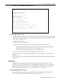
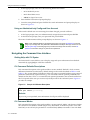
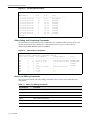
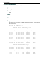
Factory Default Settings ................................................................................................................................. 1-2
Using the Command Line Interface ................................................................................................................ 1-6
Starting a CLI Session ............................................................................................................................. 1-6
Logging In ................................................................................................................................................ 1-7
Navigating the Command Line Interface .................................................................................................. 1-8
Chapter 2: Configuring Switches in a Stack
About SecureStack C3 Switch Operation in a Stack ...................................................................................... 2-1
Installing a New Stackable System of Up to Eight Units ................................................................................ 2-2
Installing Previously-Configured Systems in a Stack ..................................................................................... 2-3
Adding a New Unit to an Existing Stack ......................................................................................................... 2-3
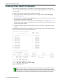
Creating a Virtual Switch Configuration .......................................................................................................... 2-4
Considerations About Using Clear Config in a Stack ..................................................................................... 2-5
Issues Related to Mixed Type Stacks ............................................................................................................ 2-5
Feature Support ....................................................................................................................................... 2-5
Configuration ............................................................................................................................................ 2-5
Stacking Configuration and Management Commands ................................................................................... 2-6
Purpose .................................................................................................................................................... 2-6
Commands ............................................................................................................................................... 2-6
show switch ........................................................................................................................................ 2-7
show switch switchtype ...................................................................................................................... 2-8
show switch stack-ports...................................................................................................................... 2-9
set switch .......................................................................................................................................... 2-10
set switch copy-fw ............................................................................................................................ 2-10
set switch description ....................................................................................................................... 2-11
set switch movemanagement ........................................................................................................... 2-11
set switch member............................................................................................................................ 2-12
clear switch member......................................................................................................................... 2-13
Chapter 3: Basic Configuration
Setting User Accounts and Passwords .......................................................................................................... 3-2
Purpose .................................................................................................................................................... 3-2
Commands ............................................................................................................................................... 3-2
show system login .............................................................................................................................. 3-2
set system login .................................................................................................................................. 3-3
clear system login ............................................................................................................................... 3-4
set password ...................................................................................................................................... 3-4
set system password length ............................................................................................................... 3-5
set system password aging ................................................................................................................3-6
set system password history .............................................................................................................. 3-6
v
show system lockout .......................................................................................................................... 3-7
set system lockout .............................................................................................................................. 3-8
Setting Basic Switch Properties ...................................................................................................................... 3-9
Purpose .................................................................................................................................................... 3-9
Commands ............................................................................................................................................... 3-9
show ip address................................................................................................................................ 3-10
set ip address ................................................................................................................................... 3-10
clear ip address ................................................................................................................................ 3-11
show ip protocol................................................................................................................................ 3-11
set ip protocol ................................................................................................................................... 3-12
show system..................................................................................................................................... 3-12
show system hardware..................................................................................................................... 3-13
show system utilization..................................................................................................................... 3-14
set system enhancedbuffermode ..................................................................................................... 3-15
show time ......................................................................................................................................... 3-15
set time ............................................................................................................................................. 3-16
show summertime ............................................................................................................................ 3-17
set summertime ................................................................................................................................ 3-17
set summertime date ........................................................................................................................ 3-18
set summertime recurring ................................................................................................................. 3-18
clear summertime ............................................................................................................................. 3-19
set prompt......................................................................................................................................... 3-19
show banner motd ............................................................................................................................ 3-20
set banner motd................................................................................................................................ 3-20
clear banner motd............................................................................................................................. 3-21
show version..................................................................................................................................... 3-21
set system name .............................................................................................................................. 3-22
set system location ........................................................................................................................... 3-24
set system contact............................................................................................................................ 3-24
set width ........................................................................................................................................... 3-25
set length .......................................................................................................................................... 3-25
show logout ...................................................................................................................................... 3-26
set logout ......................................................................................................................................... 3-26
show console .................................................................................................................................... 3-27
set console baud .............................................................................................................................. 3-28
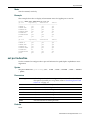
Activating Licensed Features ....................................................................................................................... 3-29
License Key Field Descriptions .............................................................................................................. 3-29
Licensing Procedure in a Stack Environment ........................................................................................ 3-29
Adding a New Member to a Licensed Stack .......................................................................................... 3-30
Clearing, Showing, and Moving Licenses .............................................................................................. 3-30
Commands ............................................................................................................................................. 3-30
set license......................................................................................................................................... 3-31
show license ..................................................................................................................................... 3-32
clear license...................................................................................................................................... 3-33
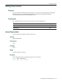
Configuring Power over Ethernet (PoE) ....................................................................................................... 3-34
Purpose .................................................................................................................................................. 3-34
Commands ............................................................................................................................................. 3-34
show inlinepower .............................................................................................................................. 3-35
set inlinepower threshold.................................................................................................................. 3-35
set inlinepower trap .......................................................................................................................... 3-36
show port inlinepower ....................................................................................................................... 3-36
set port inlinepower .......................................................................................................................... 3-37
Downloading a New Firmware Image ........................................................................................................... 3-38
Downloading from a TFTP Server .......................................................................................................... 3-38
Downloading via the Serial Port ............................................................................................................. 3-38
vi
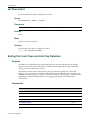
Reviewing and Selecting a Boot Firmware Image ........................................................................................ 3-41
Purpose .................................................................................................................................................. 3-41
Commands ............................................................................................................................................. 3-41
show boot system ............................................................................................................................. 3-41
set boot system ................................................................................................................................ 3-42
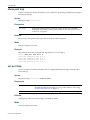
Starting and Configuring Telnet .................................................................................................................... 3-43
Purpose .................................................................................................................................................. 3-43
Commands ............................................................................................................................................. 3-43
show telnet ....................................................................................................................................... 3-43
set telnet ........................................................................................................................................... 3-44
telnet................................................................................................................................................. 3-44
Managing Switch Configuration and Files .................................................................................................... 3-45
Configuration Persistence Mode ............................................................................................................ 3-45
Purpose .................................................................................................................................................. 3-45
Commands ............................................................................................................................................. 3-45
show snmp persistmode ................................................................................................................... 3-46
set snmp persistmode ...................................................................................................................... 3-46
save config ....................................................................................................................................... 3-47
dir...................................................................................................................................................... 3-47
show config....................................................................................................................................... 3-48
configure ........................................................................................................................................... 3-49
copy .................................................................................................................................................. 3-50
delete................................................................................................................................................ 3-50
show tftp settings.............................................................................................................................. 3-51
set tftp timeout .................................................................................................................................. 3-51
clear tftp timeout ............................................................................................................................... 3-52
set tftp retry....................................................................................................................................... 3-52
clear tftp retry.................................................................................................................................... 3-53
Configuring CDP ........................................................................................................................................... 3-54
Purpose .................................................................................................................................................. 3-54
Commands ............................................................................................................................................. 3-54
show cdp .......................................................................................................................................... 3-54
set cdp state ..................................................................................................................................... 3-56
set cdp auth ...................................................................................................................................... 3-56
set cdp interval ................................................................................................................................. 3-57
set cdp hold-time .............................................................................................................................. 3-58
clear cdp ........................................................................................................................................... 3-58
show neighbors ................................................................................................................................ 3-59
Configuring Cisco Discovery Protocol .......................................................................................................... 3-60
Purpose .................................................................................................................................................. 3-60
Commands ............................................................................................................................................. 3-60
show ciscodp .................................................................................................................................... 3-60
show ciscodp port info ...................................................................................................................... 3-61
set ciscodp status ............................................................................................................................. 3-62
set ciscodp timer............................................................................................................................... 3-63
set ciscodp holdtime ......................................................................................................................... 3-63
set ciscodp port ................................................................................................................................ 3-64
clear ciscodp..................................................................................................................................... 3-65
Clearing and Closing the CLI ........................................................................................................................ 3-67
Purpose .................................................................................................................................................. 3-67
Commands ............................................................................................................................................. 3-67
cls (clear screen) .............................................................................................................................. 3-67
exit .................................................................................................................................................... 3-68
Resetting the Switch ..................................................................................................................................... 3-69
Purpose .................................................................................................................................................. 3-69
Commands ............................................................................................................................................. 3-69
vii
reset.................................................................................................................................................. 3-69
clear config ....................................................................................................................................... 3-70
Using and Configuring WebView .................................................................................................................. 3-71
Purpose .................................................................................................................................................. 3-71
Commands ............................................................................................................................................. 3-71
show webview .................................................................................................................................. 3-71
set webview ...................................................................................................................................... 3-72
show ssl............................................................................................................................................ 3-72
set ssl ............................................................................................................................................... 3-73
Chapter 4: Port Configuration
Port Configuration Summary .......................................................................................................................... 4-1
Port String Syntax Used in the CLI .......................................................................................................... 4-1
Reviewing Port Status .................................................................................................................................... 4-2
Purpose .................................................................................................................................................... 4-2
Commands ............................................................................................................................................... 4-2
show port ............................................................................................................................................ 4-3
show port status ................................................................................................................................. 4-4
show port counters ............................................................................................................................. 4-5
Disabling / Enabling and Naming Ports .......................................................................................................... 4-6
Purpose .................................................................................................................................................... 4-6
Commands ............................................................................................................................................... 4-6
set port disable ................................................................................................................................... 4-7
set port enable.................................................................................................................................... 4-8
show port alias.................................................................................................................................... 4-8
set port alias ....................................................................................................................................... 4-9
Setting Speed and Duplex Mode .................................................................................................................... 4-9
Purpose .................................................................................................................................................... 4-9
Commands ............................................................................................................................................... 4-9
show port speed ............................................................................................................................... 4-10
set port speed................................................................................................................................... 4-10
show port duplex .............................................................................................................................. 4-11
set port duplex .................................................................................................................................. 4-11
Enabling / Disabling Jumbo Frame Support ................................................................................................. 4-12
Purpose .................................................................................................................................................. 4-12
Commands ............................................................................................................................................. 4-12
show port jumbo ............................................................................................................................... 4-12
set port jumbo................................................................................................................................... 4-14
clear port jumbo ................................................................................................................................ 4-14
Setting Auto-Negotiation and Advertised Ability ........................................................................................... 4-15
Purpose .................................................................................................................................................. 4-15
Commands ............................................................................................................................................. 4-15
show port negotiation ....................................................................................................................... 4-15
set port negotiation ........................................................................................................................... 4-16
show port advertise .......................................................................................................................... 4-16
set port advertise .............................................................................................................................. 4-17
clear port advertise ........................................................................................................................... 4-18
Setting Flow Control ..................................................................................................................................... 4-19
Purpose .................................................................................................................................................. 4-19
Commands ............................................................................................................................................. 4-19
show flowcontrol ............................................................................................................................... 4-19
set flowcontrol................................................................................................................................... 4-20
Setting Port Link Traps and Link Flap Detection .......................................................................................... 4-20
Purpose .................................................................................................................................................. 4-20
Commands ............................................................................................................................................. 4-20
viii
show port trap................................................................................................................................... 4-22
set port trap ...................................................................................................................................... 4-22
show linkflap ..................................................................................................................................... 4-23
set linkflap globalstate ...................................................................................................................... 4-25
set linkflap portstate.......................................................................................................................... 4-26
set linkflap interval ............................................................................................................................ 4-26
set linkflap action .............................................................................................................................. 4-27
clear linkflap action ........................................................................................................................... 4-27
set linkflap threshold......................................................................................................................... 4-28
set linkflap downtime ........................................................................................................................ 4-28
clear linkflap down ............................................................................................................................ 4-29
clear linkflap...................................................................................................................................... 4-29
Configuring Broadcast Suppression ............................................................................................................. 4-30
Purpose .................................................................................................................................................. 4-30
Commands ............................................................................................................................................. 4-30
show port broadcast ......................................................................................................................... 4-30
set port broadcast............................................................................................................................. 4-31
clear port broadcast.......................................................................................................................... 4-31
Port Mirroring ................................................................................................................................................ 4-33
Mirroring Features .................................................................................................................................. 4-33
Remote Port Mirroring ............................................................................................................................ 4-33
Purpose .................................................................................................................................................. 4-34
Commands ............................................................................................................................................. 4-34
show port mirroring........................................................................................................................... 4-35
set port mirroring .............................................................................................................................. 4-36
clear port mirroring ........................................................................................................................... 4-37
set mirror vlan ................................................................................................................................... 4-37
clear mirror vlan ................................................................................................................................ 4-38
Link Aggregation Control Protocol (LACP) ................................................................................................... 4-38
LACP Operation ..................................................................................................................................... 4-39
LACP Terminology ................................................................................................................................. 4-39
SecureStack C3 Usage Considerations ................................................................................................. 4-40
Commands ............................................................................................................................................. 4-41
show lacp.......................................................................................................................................... 4-41
set lacp ............................................................................................................................................. 4-43
set lacp asyspri................................................................................................................................. 4-44
set lacp aadminkey........................................................................................................................... 4-44
clear lacp .......................................................................................................................................... 4-45
set lacp static.................................................................................................................................... 4-46
clear lacp static ................................................................................................................................. 4-46
set lacp singleportlag........................................................................................................................ 4-47
clear lacp singleportlag..................................................................................................................... 4-48
show port lacp .................................................................................................................................. 4-48
set port lacp ...................................................................................................................................... 4-50
clear port lacp ................................................................................................................................... 4-52
Configuring Protected Ports ......................................................................................................................... 4-53
Protected Port Operation ....................................................................................................................... 4-53
Commands ............................................................................................................................................. 4-53
set port protected.............................................................................................................................. 4-54
show port protected .......................................................................................................................... 4-54
clear port protected........................................................................................................................... 4-55
set port protected name.................................................................................................................... 4-56
show port protected name ................................................................................................................ 4-56
clear port protected name................................................................................................................. 4-57
ix
Chapter 5: SNMP Configuration
SNMP Configuration Summary ...................................................................................................................... 5-1
SNMPv1 and SNMPv2c ........................................................................................................................... 5-1
SNMPv3 ................................................................................................................................................... 5-2
About SNMP Security Models and Levels ............................................................................................... 5-2
Using SNMP Contexts to Access Specific MIBs ...................................................................................... 5-3
Configuration Considerations ................................................................................................................... 5-3
Reviewing SNMP Statistics ............................................................................................................................ 5-4
Purpose .................................................................................................................................................... 5-4
Commands ............................................................................................................................................... 5-4
show snmp engineid........................................................................................................................... 5-4
show snmp counters........................................................................................................................... 5-5
Configuring SNMP Users, Groups, and Communities .................................................................................... 5-8
Purpose .................................................................................................................................................... 5-8
Commands ............................................................................................................................................... 5-8
show snmp user ................................................................................................................................. 5-9
set snmp user ................................................................................................................................... 5-10
clear snmp user ................................................................................................................................ 5-11
show snmp group ............................................................................................................................. 5-11
set snmp group ................................................................................................................................. 5-12
clear snmp group .............................................................................................................................. 5-13
show snmp community ..................................................................................................................... 5-13
set snmp community......................................................................................................................... 5-14
clear snmp community...................................................................................................................... 5-15
Configuring SNMP Access Rights ................................................................................................................ 5-16
Purpose .................................................................................................................................................. 5-16
Commands ............................................................................................................................................. 5-16
show snmp access ........................................................................................................................... 5-16
set snmp access............................................................................................................................... 5-18
clear snmp access............................................................................................................................ 5-19
Configuring SNMP MIB Views ...................................................................................................................... 5-20
Purpose .................................................................................................................................................. 5-20
Commands ............................................................................................................................................. 5-20
show snmp view ............................................................................................................................... 5-20
show snmp context........................................................................................................................... 5-22
set snmp view................................................................................................................................... 5-23
clear snmp view................................................................................................................................ 5-24
Configuring SNMP Target Parameters ......................................................................................................... 5-25
Purpose .................................................................................................................................................. 5-25
Commands ............................................................................................................................................. 5-25
show snmp targetparams ................................................................................................................. 5-25
set snmp targetparams..................................................................................................................... 5-27
clear snmp targetparams.................................................................................................................. 5-28
Configuring SNMP Target Addresses .......................................................................................................... 5-29
Purpose .................................................................................................................................................. 5-29
Commands ............................................................................................................................................. 5-29
show snmp targetaddr ...................................................................................................................... 5-29
set snmp targetaddr.......................................................................................................................... 5-30
clear snmp targetaddr....................................................................................................................... 5-31
Configuring SNMP Notification Parameters ................................................................................................. 5-33
About SNMP Notify Filters ..................................................................................................................... 5-33
Purpose .................................................................................................................................................. 5-33
Commands ............................................................................................................................................. 5-33
show newaddrtrap ............................................................................................................................ 5-34
set newaddrtrap................................................................................................................................ 5-35
x
show snmp notify .............................................................................................................................. 5-36
set snmp notify ................................................................................................................................. 5-37
clear snmp notify .............................................................................................................................. 5-38
show snmp notifyfilter ....................................................................................................................... 5-38
set snmp notifyfilter........................................................................................................................... 5-39
clear snmp notifyfilter........................................................................................................................ 5-40
show snmp notifyprofile .................................................................................................................... 5-40
set snmp notifyprofile........................................................................................................................ 5-41
clear snmp notifyprofile..................................................................................................................... 5-42
Creating a Basic SNMP Trap Configuration ................................................................................................. 5-43
Example ................................................................................................................................................. 5-43
Chapter 6: Spanning Tree Configuration
Spanning Tree Configuration Summary ......................................................................................................... 6-1
Overview: Single, Rapid, and Multiple Spanning Tree Protocols ............................................................. 6-1
Spanning Tree Features .......................................................................................................................... 6-2
Reviewing and Setting Spanning Tree Bridge Parameters ............................................................................ 6-3
Purpose .................................................................................................................................................... 6-3
Commands ............................................................................................................................................... 6-3
show spantree stats............................................................................................................................ 6-5
set spantree........................................................................................................................................ 6-7
show spantree version........................................................................................................................ 6-7
set spantree version ........................................................................................................................... 6-8
clear spantree version ........................................................................................................................ 6-8
show spantree bpdu-forwarding ......................................................................................................... 6-9
set spantree bpdu-forwarding............................................................................................................. 6-9
show spantree bridgeprioritymode ................................................................................................... 6-10
set spantree bridgeprioritymode ....................................................................................................... 6-10
clear spantree bridgeprioritymode .................................................................................................... 6-11
show spantree mstilist ...................................................................................................................... 6-11
set spantree msti .............................................................................................................................. 6-12
clear spantree msti ........................................................................................................................... 6-12
show spantree mstmap .................................................................................................................... 6-13
set spantree mstmap ........................................................................................................................ 6-13
clear spantree mstmap ..................................................................................................................... 6-14
show spantree vlanlist ...................................................................................................................... 6-14
show spantree mstcfgid .................................................................................................................... 6-15
set spantree mstcfgid ....................................................................................................................... 6-16
clear spantree mstcfgid .................................................................................................................... 6-16
set spantree priority .......................................................................................................................... 6-17
clear spantree priority ....................................................................................................................... 6-17
set spantree hello ............................................................................................................................. 6-18
clear spantree hello .......................................................................................................................... 6-18
set spantree maxage ........................................................................................................................ 6-19
clear spantree maxage ..................................................................................................................... 6-19
set spantree fwddelay....................................................................................................................... 6-20
clear spantree fwddelay.................................................................................................................... 6-20
show spantree backuproot ............................................................................................................... 6-21
set spantree backuproot ................................................................................................................... 6-21
clear spantree backuproot ................................................................................................................ 6-22
show spantree tctrapsuppress.......................................................................................................... 6-22
set spantree tctrapsuppress ............................................................................................................. 6-23
clear spantree tctrapsuppress .......................................................................................................... 6-24
set spantree protomigration .............................................................................................................. 6-24
show spantree spanguard ................................................................................................................ 6-25
xi
set spantree spanguard .................................................................................................................... 6-25
clear spantree spanguard ................................................................................................................. 6-26
show spantree spanguardtimeout .................................................................................................... 6-26
set spantree spanguardtimeout ........................................................................................................ 6-27
clear spantree spanguardtimeout ..................................................................................................... 6-27
show spantree spanguardlock .......................................................................................................... 6-28
clear / set spantree spanguardlock................................................................................................... 6-28
show spantree spanguardtrapenable ............................................................................................... 6-29
set spantree spanguardtrapenable ................................................................................................... 6-29
clear spantree spanguardtrapenable ................................................................................................ 6-30
show spantree legacypathcost ......................................................................................................... 6-30
set spantree legacypathcost............................................................................................................. 6-31
clear spantree legacypathcost .......................................................................................................... 6-31
Reviewing and Setting Spanning Tree Port Parameters .............................................................................. 6-32
Purpose .................................................................................................................................................. 6-32
Commands ............................................................................................................................................. 6-32
set spantree portadmin..................................................................................................................... 6-33
clear spantree portadmin.................................................................................................................. 6-33
show spantree portadmin ................................................................................................................. 6-34
show spantree portpri ....................................................................................................................... 6-34
set spantree portpri........................................................................................................................... 6-35
clear spantree portpri........................................................................................................................ 6-35
show spantree adminpathcost .......................................................................................................... 6-36
set spantree adminpathcost ............................................................................................................. 6-37
clear spantree adminpathcost .......................................................................................................... 6-37
show spantree adminedge ............................................................................................................... 6-38
set spantree adminedge ................................................................................................................... 6-38
clear spantree adminedge ................................................................................................................ 6-39
Chapter 7: 802.1Q VLAN Configuration
VLAN Configuration Summary ....................................................................................................................... 7-1
Port String Syntax Used in the CLI .......................................................................................................... 7-1
Creating a Secure Management VLAN .................................................................................................... 7-1
Viewing VLANs ............................................................................................................................................... 7-3
Purpose .................................................................................................................................................... 7-3
Commands ............................................................................................................................................... 7-3
show vlan............................................................................................................................................ 7-3
Creating and Naming Static VLANs ............................................................................................................... 7-5
Purpose .................................................................................................................................................... 7-5
Commands ............................................................................................................................................... 7-5
set vlan ............................................................................................................................................... 7-5
set vlan name ..................................................................................................................................... 7-6
clear vlan ............................................................................................................................................ 7-6
clear vlan name .................................................................................................................................. 7-7
Assigning Port VLAN IDs (PVIDs) and Ingress Filtering ................................................................................ 7-8
Purpose .................................................................................................................................................... 7-8
Commands ............................................................................................................................................... 7-8
show port vlan .................................................................................................................................... 7-8
set port vlan ........................................................................................................................................ 7-9
clear port vlan ................................................................................................................................... 7-10
show port ingress filter...................................................................................................................... 7-10
set port ingress filter ......................................................................................................................... 7-11
show port discard ............................................................................................................................. 7-12
set port discard ................................................................................................................................. 7-13
xii
Configuring the VLAN Egress List ................................................................................................................ 7-14
Purpose .................................................................................................................................................. 7-14
Commands ............................................................................................................................................. 7-14
show port egress .............................................................................................................................. 7-15
set vlan forbidden ............................................................................................................................. 7-15
set vlan egress ................................................................................................................................. 7-16
clear vlan egress .............................................................................................................................. 7-17
show vlan dynamicegress ................................................................................................................ 7-18
set vlan dynamicegress .................................................................................................................... 7-19
Setting the Host VLAN .................................................................................................................................. 7-20
Purpose .................................................................................................................................................. 7-20
Commands ............................................................................................................................................. 7-20
show host vlan.................................................................................................................................. 7-20
set host vlan ..................................................................................................................................... 7-21
clear host vlan .................................................................................................................................. 7-22
Enabling/Disabling GVRP (GARP VLAN Registration Protocol) .................................................................. 7-23
About GARP VLAN Registration Protocol (GVRP) ................................................................................ 7-23
Purpose .................................................................................................................................................. 7-24
Commands ............................................................................................................................................. 7-24
show gvrp ......................................................................................................................................... 7-25
show garp timer ................................................................................................................................ 7-25
set gvrp............................................................................................................................................. 7-27
clear gvrp .......................................................................................................................................... 7-27
set garp timer.................................................................................................................................... 7-28
Chapter 8: Policy Classification Configuration
Policy Classification Configuration Summary ................................................................................................. 8-1
Configuring Policy Profiles .............................................................................................................................. 8-2
Purpose .................................................................................................................................................... 8-2
Commands ............................................................................................................................................... 8-2
show policy profile .............................................................................................................................. 8-2
set policy profile .................................................................................................................................. 8-4
clear policy profile ............................................................................................................................... 8-5
Configuring Classification Rules ..................................................................................................................... 8-6
Purpose .................................................................................................................................................... 8-6
Commands ............................................................................................................................................... 8-6
show policy rule .................................................................................................................................. 8-6
show policy capability ......................................................................................................................... 8-9
set policy rule.................................................................................................................................... 8-11
clear policy rule................................................................................................................................. 8-13
clear policy all-rules .......................................................................................................................... 8-14
Assigning Ports to Policy Profiles ................................................................................................................. 8-15
Purpose .................................................................................................................................................. 8-15
Commands ............................................................................................................................................. 8-15
set policy port ................................................................................................................................... 8-15
clear policy port ................................................................................................................................ 8-16
Configuring Policy Class of Service (CoS) ................................................................................................... 8-17
Using Port-Based or Policy-Based CoS Settings ................................................................................... 8-17
Commands ............................................................................................................................................. 8-17
set cos state ..................................................................................................................................... 8-18
show cos state.................................................................................................................................. 8-18
clear cos state .................................................................................................................................. 8-19
set cos settings................................................................................................................................. 8-19
clear cos settings .............................................................................................................................. 8-20
show cos settings ............................................................................................................................. 8-21
clear cos all-entries........................................................................................................................... 8-21
xiii
Chapter 9: Port Priority Configuration
Port Priority Configuration Summary .............................................................................................................. 9-1
Configuring Port Priority ................................................................................................................................. 9-2
Purpose .................................................................................................................................................... 9-2
Commands ............................................................................................................................................... 9-2
show port priority ................................................................................................................................ 9-2
set port priority.................................................................................................................................... 9-3
clear port priority................................................................................................................................. 9-4
Configuring Priority to Transmit Queue Mapping ........................................................................................... 9-5
Purpose .................................................................................................................................................... 9-5
Commands ............................................................................................................................................... 9-5
show port priority-queue ..................................................................................................................... 9-5
set port priority-queue......................................................................................................................... 9-6
clear port priority-queue...................................................................................................................... 9-7
Configuring Quality of Service (QoS) ............................................................................................................. 9-8
Purpose .................................................................................................................................................... 9-8
Command Descriptions ............................................................................................................................ 9-8
show port txq ...................................................................................................................................... 9-8
set port txq.......................................................................................................................................... 9-9
clear port txq..................................................................................................................................... 9-10
Chapter 10: IGMP Configuration
IGMP Overview ............................................................................................................................................ 10-1
About IP Multicast Group Management ................................................................................................. 10-1
About Multicasting .................................................................................................................................. 10-2
Configuring IGMP at Layer 2 ........................................................................................................................ 10-2
Purpose .................................................................................................................................................. 10-2
Commands ............................................................................................................................................. 10-2
show igmpsnooping .......................................................................................................................... 10-3
set igmpsnooping adminmode.......................................................................................................... 10-3
set igmpsnooping interfacemode...................................................................................................... 10-4
set igmpsnooping groupmembershipinterval .................................................................................... 10-5
set igmpsnooping maxresponse ....................................................................................................... 10-5
set igmpsnooping mcrtrexpiretime.................................................................................................... 10-6
set igmpsnooping add-static ............................................................................................................. 10-7
set igmpsnooping remove-static ....................................................................................................... 10-7
show igmpsnooping static ................................................................................................................ 10-8
show igmpsnooping mfdb ................................................................................................................. 10-9
clear igmpsnooping ........................................................................................................................ 10-10
Configuring IGMP on Routing Interfaces .................................................................................................... 10-11
Purpose ................................................................................................................................................ 10-11
Commands ........................................................................................................................................... 10-11
ip igmp ............................................................................................................................................ 10-12
ip igmp enable ................................................................................................................................ 10-12
ip igmp version ............................................................................................................................... 10-13
show ip igmp interface .................................................................................................................... 10-13
show ip igmp groups....................................................................................................................... 10-14
ip igmp query-interval ..................................................................................................................... 10-15
ip igmp query-max-response-time .................................................................................................. 10-15
ip igmp startup-query-interval ......................................................................................................... 10-16
ip igmp startup-query-count ............................................................................................................10-16
ip igmp last-member-query-interval ................................................................................................ 10-17
ip igmp last-member-query-count ................................................................................................... 10-18
ip igmp robustness ......................................................................................................................... 10-18
xiv
Chapter 11: Logging and Network Management
Configuring System Logging ........................................................................................................................ 11-1
Purpose .................................................................................................................................................. 11-1
Commands ............................................................................................................................................. 11-1
show logging server.......................................................................................................................... 11-2
set logging server ............................................................................................................................. 11-3
clear logging server .......................................................................................................................... 11-4
show logging default......................................................................................................................... 11-4
set logging default ............................................................................................................................ 11-5
clear logging default ......................................................................................................................... 11-6
show logging application .................................................................................................................. 11-7
set logging application ...................................................................................................................... 11-8
clear logging application ................................................................................................................... 11-9
show logging local ............................................................................................................................ 11-9
set logging local.............................................................................................................................. 11-10
clear logging local........................................................................................................................... 11-10
show logging buffer ........................................................................................................................ 11-11
Monitoring Network Events and Status ...................................................................................................... 11-12
Purpose ................................................................................................................................................ 11-12
Commands ........................................................................................................................................... 11-12
history ............................................................................................................................................. 11-12
show history.................................................................................................................................... 11-13
set history ....................................................................................................................................... 11-13
ping................................................................................................................................................. 11-14
show users ..................................................................................................................................... 11-15
disconnect ...................................................................................................................................... 11-15
Managing Switch Network Addresses and Routes ..................................................................................... 11-17
Purpose ................................................................................................................................................ 11-17
Commands ........................................................................................................................................... 11-17
show arp ......................................................................................................................................... 11-17
set arp............................................................................................................................................. 11-18
clear arp.......................................................................................................................................... 11-19
traceroute ....................................................................................................................................... 11-19
show mac ....................................................................................................................................... 11-20
show mac agetime.......................................................................................................................... 11-22
set mac agetime ............................................................................................................................. 11-22
clear mac agetime .......................................................................................................................... 11-23
set mac algorithm ........................................................................................................................... 11-23
show mac algorithm........................................................................................................................ 11-24
clear mac algorithm ........................................................................................................................ 11-24
set mac multicast ............................................................................................................................ 11-25
clear mac address .......................................................................................................................... 11-25
Configuring Simple Network Time Protocol (SNTP) ................................................................................... 11-27
Purpose ................................................................................................................................................ 11-27
Commands ........................................................................................................................................... 11-27
show sntp ....................................................................................................................................... 11-27
set sntp client.................................................................................................................................. 11-29
clear sntp client............................................................................................................................... 11-29
set sntp server ................................................................................................................................ 11-30
clear sntp server ............................................................................................................................. 11-30
set sntp poll-interval........................................................................................................................ 11-31
clear sntp poll-interval..................................................................................................................... 11-31
set sntp poll-retry ............................................................................................................................ 11-32
clear sntp poll-retry ......................................................................................................................... 11-32
set sntp poll-timeout ....................................................................................................................... 11-33
xv
clear sntp poll-timeout .................................................................................................................... 11-33
Configuring Node Aliases ........................................................................................................................... 11-34
Purpose ................................................................................................................................................ 11-34
Commands ........................................................................................................................................... 11-34
show nodealias config .................................................................................................................... 11-34
set nodealias .................................................................................................................................. 11-35
clear nodealias config ..................................................................................................................... 11-36
Chapter 12: Configuring RMON
RMON Monitoring Group Functions ............................................................................................................. 12-1
Statistics Group Commands ......................................................................................................................... 12-3
Purpose .................................................................................................................................................. 12-3
Commands ............................................................................................................................................. 12-3
show rmon stats ............................................................................................................................... 12-3
set rmon stats ................................................................................................................................... 12-5
clear rmon stats ................................................................................................................................ 12-6
History Group Commands ............................................................................................................................ 12-7
Purpose .................................................................................................................................................. 12-7
Commands ............................................................................................................................................. 12-7
show rmon history ............................................................................................................................ 12-7
set rmon history ................................................................................................................................ 12-8
clear rmon history ............................................................................................................................. 12-9
Alarm Group Commands ............................................................................................................................ 12-10
Purpose ................................................................................................................................................ 12-10
Commands ........................................................................................................................................... 12-10
show rmon alarm ............................................................................................................................ 12-10
set rmon alarm properties............................................................................................................... 12-11
set rmon alarm status ..................................................................................................................... 12-13
clear rmon alarm............................................................................................................................. 12-14
Event Group Commands ............................................................................................................................ 12-15
Purpose ................................................................................................................................................ 12-15
Commands ........................................................................................................................................... 12-15
show rmon event ............................................................................................................................ 12-15
set rmon event properties ............................................................................................................... 12-16
set rmon event status ..................................................................................................................... 12-17
clear rmon event............................................................................................................................. 12-18
Filter Group Commands ............................................................................................................................. 12-19
Commands ........................................................................................................................................... 12-19
show rmon channel ........................................................................................................................ 12-19
set rmon channel ............................................................................................................................ 12-20
clear rmon channel ......................................................................................................................... 12-21
show rmon filter .............................................................................................................................. 12-21
set rmon filter .................................................................................................................................. 12-22
clear rmon filter ............................................................................................................................... 12-23
Packet Capture Commands ....................................................................................................................... 12-24
Purpose ................................................................................................................................................ 12-24
Commands ........................................................................................................................................... 12-24
show rmon capture ......................................................................................................................... 12-24
set rmon capture............................................................................................................................. 12-25
clear rmon capture.......................................................................................................................... 12-26
xvi
Chapter 13: Configuring DHCP Server
DHCP Overview ........................................................................................................................................... 13-1
DHCP Relay Agent ................................................................................................................................ 13-1
DHCP Server ......................................................................................................................................... 13-1
DHCP Server Configuration Task List .................................................................................................... 13-2
Configuring General DHCP Server Parameters ........................................................................................... 13-3
Purpose .................................................................................................................................................. 13-3
Commands ............................................................................................................................................. 13-3
set dhcp ............................................................................................................................................ 13-3
set dhcp bootp .................................................................................................................................. 13-4
set dhcp conflict logging ................................................................................................................... 13-4
show dhcp conflict ............................................................................................................................ 13-5
clear dhcp conflict............................................................................................................................. 13-5
set dhcp exclude............................................................................................................................... 13-6
clear dhcp exclude............................................................................................................................ 13-7
set dhcp ping .................................................................................................................................... 13-7
clear dhcp ping ................................................................................................................................. 13-8
show dhcp binding............................................................................................................................ 13-8
clear dhcp binding ............................................................................................................................ 13-9
show dhcp server statistics............................................................................................................... 13-9
clear dhcp server statistics ............................................................................................................. 13-10
Configuring IP Address Pools ..................................................................................................................... 13-11
Manual Pool Configuration Considerations .......................................................................................... 13-11
Purpose ................................................................................................................................................ 13-11
Commands ........................................................................................................................................... 13-11
set dhcp pool .................................................................................................................................. 13-13
clear dhcp pool ............................................................................................................................... 13-13
set dhcp pool network..................................................................................................................... 13-14
clear dhcp pool network.................................................................................................................. 13-14
set dhcp pool hardware-address .................................................................................................... 13-15
clear dhcp pool hardware-address ................................................................................................. 13-16
set dhcp pool host .......................................................................................................................... 13-16
clear dhcp pool host ....................................................................................................................... 13-17
set dhcp pool client-identifier .......................................................................................................... 13-17
clear dhcp pool client-identifier ....................................................................................................... 13-18
set dhcp pool client-name............................................................................................................... 13-19
clear dhcp pool client-name............................................................................................................13-19
set dhcp pool bootfile...................................................................................................................... 13-20
clear dhcp pool bootfile................................................................................................................... 13-20
set dhcp pool next-server ............................................................................................................... 13-21
clear dhcp pool next-server ............................................................................................................13-21
set dhcp pool lease......................................................................................................................... 13-22
clear dhcp pool lease...................................................................................................................... 13-22
set dhcp pool default-router ............................................................................................................13-23
clear dhcp pool default-router......................................................................................................... 13-24
set dhcp pool dns-server ................................................................................................................ 13-24
clear dhcp pool dns-server ............................................................................................................. 13-25
set dhcp pool domain-name ........................................................................................................... 13-25
clear dhcp pool domain-name ........................................................................................................ 13-26
set dhcp pool netbios-name-server ................................................................................................ 13-26
clear dhcp pool netbios-name-server ............................................................................................. 13-27
set dhcp pool netbios-node-type .................................................................................................... 13-27
clear dhcp pool netbios-node-type ................................................................................................. 13-28
set dhcp pool option ....................................................................................................................... 13-28
clear dhcp pool option .................................................................................................................... 13-29
show dhcp pool configuration ......................................................................................................... 13-30
xvii
Chapter 14: Preparing for Router Mode
Pre-Routing Configuration Tasks ................................................................................................................. 14-1
Example ................................................................................................................................................. 14-2
Enabling Router Configuration Modes .......................................................................................................... 14-3
Chapter 15: IP Configuration
Configuring Routing Interface Settings ......................................................................................................... 15-1
Purpose .................................................................................................................................................. 15-1
Commands ............................................................................................................................................. 15-1
show interface .................................................................................................................................. 15-2
interface............................................................................................................................................ 15-3
show ip interface............................................................................................................................... 15-4
ip address ......................................................................................................................................... 15-5
show running-config ......................................................................................................................... 15-6
no shutdown ..................................................................................................................................... 15-7
no ip routing...................................................................................................................................... 15-7
Configuring Tunnel Interfaces ...................................................................................................................... 15-8
Purpose .................................................................................................................................................. 15-8
Commands ............................................................................................................................................. 15-8
interface tunnel ................................................................................................................................. 15-8
tunnel source .................................................................................................................................... 15-9
tunnel destination ............................................................................................................................. 15-9
tunnel mode.................................................................................................................................... 15-10
show interface tunnel...................................................................................................................... 15-11
Reviewing and Configuring the ARP Table ................................................................................................ 15-12
Purpose ................................................................................................................................................ 15-12
Commands ........................................................................................................................................... 15-12
show ip arp ..................................................................................................................................... 15-12
arp .................................................................................................................................................. 15-14
ip proxy-arp..................................................................................................................................... 15-15
arp timeout...................................................................................................................................... 15-15
clear arp-cache ............................................................................................................................... 15-16
Configuring Broadcast Settings .................................................................................................................. 15-17
Purpose ................................................................................................................................................ 15-17
Commands ........................................................................................................................................... 15-17
ip directed-broadcast ...................................................................................................................... 15-17
ip helper-address ............................................................................................................................ 15-18
Reviewing IP Traffic and Configuring Routes ............................................................................................. 15-19
Purpose ................................................................................................................................................ 15-19
Commands ........................................................................................................................................... 15-19
show ip route .................................................................................................................................. 15-19
ip route............................................................................................................................................ 15-20
ping................................................................................................................................................. 15-21
traceroute ....................................................................................................................................... 15-22
Chapter 16: IPv4 Routing Protocol Configuration
Activating Advanced Routing Features ........................................................................................................ 16-1
Configuring RIP ............................................................................................................................................ 16-2
Purpose .................................................................................................................................................. 16-2
RIP Configuration Task List and Commands ......................................................................................... 16-2
router rip ........................................................................................................................................... 16-3
ip rip enable ...................................................................................................................................... 16-3
distance ............................................................................................................................................ 16-4
ip rip send version ............................................................................................................................ 16-5
ip rip receive version......................................................................................................................... 16-5
xviii
ip rip authentication-key.................................................................................................................... 16-6
ip rip message-digest-key................................................................................................................. 16-7
no auto-summary.............................................................................................................................. 16-8
split-horizon poison........................................................................................................................... 16-9
passive-interface .............................................................................................................................. 16-9
receive-interface ............................................................................................................................. 16-10
redistribute...................................................................................................................................... 16-11
Configuring OSPF ...................................................................................................................................... 16-12
Purpose ................................................................................................................................................ 16-12
OSPF Configuration Task List and Commands ................................................................................... 16-12
router id .......................................................................................................................................... 16-14
router ospf ...................................................................................................................................... 16-14
1583compatibility ............................................................................................................................ 16-15
ip ospf enable ................................................................................................................................. 16-16
ip ospf areaid .................................................................................................................................. 16-16
ip ospf cost ..................................................................................................................................... 16-17
ip ospf priority ................................................................................................................................. 16-17
timers spf ........................................................................................................................................ 16-18
ip ospf retransmit-interval ............................................................................................................... 16-19
ip ospf transmit-delay ..................................................................................................................... 16-19
ip ospf hello-interval........................................................................................................................ 16-20
ip ospf dead-interval ....................................................................................................................... 16-21
ip ospf authentication-key ............................................................................................................... 16-21
ip ospf message digest key md5 .................................................................................................... 16-22
distance ospf .................................................................................................................................. 16-23
area range ...................................................................................................................................... 16-24
area stub......................................................................................................................................... 16-24
area default cost ............................................................................................................................. 16-25
area nssa........................................................................................................................................ 16-26
area virtual-link ............................................................................................................................... 16-27
redistribute...................................................................................................................................... 16-28
show ip ospf.................................................................................................................................... 16-29
show ip ospf database.................................................................................................................... 16-30
show ip ospf interface ..................................................................................................................... 16-32
show ip ospf neighbor..................................................................................................................... 16-33
show ip ospf virtual-links................................................................................................................. 16-34
clear ip ospf process....................................................................................................................... 16-35
Configuring DVMRP ................................................................................................................................... 16-36
Purpose ................................................................................................................................................ 16-36
Commands ........................................................................................................................................... 16-36
ip dvmrp.......................................................................................................................................... 16-37
ip dvmrp enable .............................................................................................................................. 16-37
ip dvmrp metric ............................................................................................................................... 16-38
show ip dvmrp ................................................................................................................................ 16-38
Configuring IRDP ........................................................................................................................................ 16-40
Purpose ................................................................................................................................................ 16-40
Commands ........................................................................................................................................... 16-40
ip irdp enable .................................................................................................................................. 16-40
ip irdp maxadvertinterval ................................................................................................................ 16-41
ip irdp minadvertinterval ................................................................................................................. 16-41
ip irdp holdtime ............................................................................................................................... 16-42
ip irdp preference............................................................................................................................ 16-42
ip irdp broadcast ............................................................................................................................. 16-43
show ip irdp .................................................................................................................................... 16-44
xix
Configuring VRRP ...................................................................................................................................... 16-45
Purpose ................................................................................................................................................ 16-45
Commands ........................................................................................................................................... 16-45
router vrrp ....................................................................................................................................... 16-46
create.............................................................................................................................................. 16-47
address........................................................................................................................................... 16-48
priority............................................................................................................................................. 16-49
advertise-interval ............................................................................................................................ 16-50
preempt .......................................................................................................................................... 16-51
enable............................................................................................................................................. 16-52
show ip vrrp .................................................................................................................................... 16-53
Configuring PIM-SM ................................................................................................................................... 16-54
Purpose ................................................................................................................................................ 16-54
Commands ........................................................................................................................................... 16-54
ip pimsm ......................................................................................................................................... 16-55
ip pimsm staticrp............................................................................................................................. 16-55
ip pimsm enable ............................................................................................................................. 16-56
ip pimsm query-interval .................................................................................................................. 16-57
show ip pimsm................................................................................................................................ 16-57
show ip pimsm componenttable ..................................................................................................... 16-58
show ip pimsm interface ................................................................................................................. 16-59
show ip pimsm neighbor ................................................................................................................. 16-61
show ip pimsm rp............................................................................................................................ 16-62
show ip pimsm rphash .................................................................................................................... 16-63
show ip pimsm staticrp ................................................................................................................... 16-63
Chapter 17: IPv6 Management
Purpose .................................................................................................................................................. 17-1
Commands ............................................................................................................................................. 17-1
show ipv6 status ............................................................................................................................... 17-2
set ipv6 ............................................................................................................................................. 17-2
set ipv6 address ............................................................................................................................... 17-3
show ipv6 address............................................................................................................................ 17-4
clear ipv6 address ............................................................................................................................ 17-5
set ipv6 gateway............................................................................................................................... 17-6
clear ipv6 gateway............................................................................................................................ 17-7
show ipv6 neighbors......................................................................................................................... 17-7
show ipv6 netstat.............................................................................................................................. 17-8
ping ipv6 ........................................................................................................................................... 17-9
traceroute ipv6................................................................................................................................ 17-10
Chapter 18: IPv6 Configuration
Overview ....................................................................................................................................................... 18-1
Default Conditions .................................................................................................................................. 18-2
General Configuration Commands ............................................................................................................... 18-3
ipv6 forwarding ................................................................................................................................. 18-3
ipv6 hop-limit .................................................................................................................................... 18-4
ipv6 route.......................................................................................................................................... 18-4
ipv6 route distance ........................................................................................................................... 18-5
ipv6 unicast-routing .......................................................................................................................... 18-6
ping ipv6 ........................................................................................................................................... 18-7
ping ipv6 interface ............................................................................................................................ 18-8
traceroute ipv6.................................................................................................................................. 18-9
Interface Configuration Commands ............................................................................................................ 18-10
ipv6 address ................................................................................................................................... 18-10
xx
ipv6 enable ..................................................................................................................................... 18-11
ipv6 mtu .......................................................................................................................................... 18-12
Neighbor Cache and Neighbor Discovery Commands ............................................................................... 18-14
clear ipv6 neighbors ....................................................................................................................... 18-14
ipv6 nd dad attempts ...................................................................................................................... 18-15
ipv6 nd ns-interval .......................................................................................................................... 18-16
ipv6 nd reachable-time ................................................................................................................... 18-16
ipv6 nd managed-config-flag .......................................................................................................... 18-17
ipv6 nd other-config-flag ................................................................................................................. 18-18
ipv6 nd ra-interval ........................................................................................................................... 18-18
ipv6 nd ra-lifetime ........................................................................................................................... 18-19
ipv6 nd suppress-ra ........................................................................................................................ 18-19
ipv6 nd prefix .................................................................................................................................. 18-20
Query Commands ...................................................................................................................................... 18-22
show ipv6........................................................................................................................................ 18-22
show ipv6 interface......................................................................................................................... 18-23
show ipv6 neighbors....................................................................................................................... 18-24
show ipv6 route .............................................................................................................................. 18-25
show ipv6 route preferences .......................................................................................................... 18-27
show ipv6 route summary............................................................................................................... 18-28
show ipv6 traffic.............................................................................................................................. 18-29
clear ipv6 statistics ......................................................................................................................... 18-35
Chapter 19: DHCPv6 Configuration
Overview ....................................................................................................................................................... 19-1
Default Conditions .................................................................................................................................. 19-2
Global Configuration Commands ................................................................................................................. 19-2
Purpose .................................................................................................................................................. 19-2
Commands ............................................................................................................................................. 19-2
ipv6 dhcp enable .............................................................................................................................. 19-3
ipv6 dhcp relay-agent-info-opt .......................................................................................................... 19-3
ipv6 dhcp relay-agent-info-remote-id-subopt ....................................................................................19-4
ipv6 dhcp pool .................................................................................................................................. 19-4
Address Pool Configuration Commands ...................................................................................................... 19-6
Purpose .................................................................................................................................................. 19-6
Commands ............................................................................................................................................. 19-6
domain-name.................................................................................................................................... 19-6
dns-server......................................................................................................................................... 19-7
prefix-delegation ............................................................................................................................... 19-7
exit .................................................................................................................................................... 19-8
Interface Configuration Commands ............................................................................................................ 19-10
Purpose ................................................................................................................................................ 19-10
Commands ........................................................................................................................................... 19-10
ipv6 dhcp server ............................................................................................................................. 19-10
ipv6 dhcp relay ............................................................................................................................... 19-11
DHCPv6 Show Commands ........................................................................................................................ 19-13
Purpose ................................................................................................................................................ 19-13
Commands ........................................................................................................................................... 19-13
show ipv6 dhcp ............................................................................................................................... 19-13
show ipv6 dhcp interface ................................................................................................................ 19-14
show ipv6 dhcp statistics ................................................................................................................ 19-16
clear ipv6 dhcp statistics................................................................................................................. 19-17
show ipv6 dhcp pool ....................................................................................................................... 19-18
show ipv6 dhcp binding .................................................................................................................. 19-19
xxi
Chapter 20: OSPFv3 Configuration
Overview ....................................................................................................................................................... 20-1
Default Conditions .................................................................................................................................. 20-2
Global OSPFv3 Configuration Commands ................................................................................................... 20-3
Purpose .................................................................................................................................................. 20-3
Command ............................................................................................................................................... 20-3
ipv6 router id..................................................................................................................................... 20-3
ipv6 router ospf................................................................................................................................. 20-4
default-information originate ............................................................................................................. 20-4
default-metric.................................................................................................................................... 20-5
distance ospf .................................................................................................................................... 20-6
exit-overflow-interval......................................................................................................................... 20-7
external-lsdb-limit ............................................................................................................................. 20-7
maximum-paths ................................................................................................................................ 20-8
redistribute........................................................................................................................................ 20-9
Area Configuration Commands .................................................................................................................. 20-10
Purpose ................................................................................................................................................ 20-10
Commands ........................................................................................................................................... 20-10
area default-cost............................................................................................................................. 20-10
area nssa........................................................................................................................................ 20-11
area nssa default-info-originate ...................................................................................................... 20-12
area nssa no-redistribute................................................................................................................ 20-12
area nssa no-summary................................................................................................................... 20-13
area nssa translator role ................................................................................................................. 20-14
area nssa translator-stab-intv ......................................................................................................... 20-15
area range ...................................................................................................................................... 20-15
area stub......................................................................................................................................... 20-16
area stub no-summary.................................................................................................................... 20-17
area virtual-link ............................................................................................................................... 20-18
area virtual-link dead-interval ......................................................................................................... 20-18
area virtual-link hello-interval.......................................................................................................... 20-19
area virtual-link retransmit-interval ................................................................................................. 20-20
area virtual-link transmit-delay........................................................................................................ 20-20
Interface Configuration Commands ............................................................................................................ 20-22
Purpose ................................................................................................................................................ 20-22
Commands ........................................................................................................................................... 20-22
ipv6 ospf enable ............................................................................................................................. 20-22
ipv6 ospf areaid .............................................................................................................................. 20-23
ipv6 ospf cost.................................................................................................................................. 20-24
ipv6 ospf dead-interval ................................................................................................................... 20-24
ipv6 ospf hello-interval.................................................................................................................... 20-25
ipv6 ospf mtu-ignore ....................................................................................................................... 20-26
ipv6 ospf network............................................................................................................................ 20-26
ipv6 ospf priority ............................................................................................................................. 20-27
ipv6 ospf retransmit-interval ........................................................................................................... 20-28
ipv6 ospf transmit-delay.................................................................................................................. 20-28
OSPFv3 Show Commands ......................................................................................................................... 20-30
Purpose ................................................................................................................................................ 20-30
Commands ........................................................................................................................................... 20-30
show ipv6 ospf................................................................................................................................ 20-30
show ipv6 ospf area........................................................................................................................ 20-32
show ipv6 ospf abr.......................................................................................................................... 20-34
show ipv6 ospf asbr ........................................................................................................................ 20-35
show ipv6 ospf database ................................................................................................................ 20-36
show ipv6 ospf database database-summary ................................................................................ 20-39
xxii
show ipv6 ospf interface ................................................................................................................. 20-41
show ipv6 ospf interface stats ........................................................................................................ 20-43
show ipv6 ospf neighbor................................................................................................................. 20-45
show ipv6 ospf range...................................................................................................................... 20-47
show ipv6 ospf stub table ............................................................................................................... 20-48
show ipv6 ospf virtual-link............................................................................................................... 20-49
Chapter 21: Security Configuration
Overview of Security Methods ...................................................................................................................... 21-1
RADIUS Filter-ID Attribute and Dynamic Policy Profile Assignment ...................................................... 21-2
Configuring RADIUS ..................................................................................................................................... 21-4
Purpose .................................................................................................................................................. 21-4
Commands ............................................................................................................................................. 21-4
show radius ...................................................................................................................................... 21-5
set radius .......................................................................................................................................... 21-6
clear radius ....................................................................................................................................... 21-8
show radius accounting .................................................................................................................... 21-9
set radius accounting...................................................................................................................... 21-10
clear radius accounting................................................................................................................... 21-11
Configuring 802.1X Authentication ............................................................................................................. 21-12
Purpose ................................................................................................................................................ 21-12
Commands ........................................................................................................................................... 21-12
show dot1x ..................................................................................................................................... 21-13
show dot1x auth-config................................................................................................................... 21-14
set dot1x ......................................................................................................................................... 21-16
set dot1x auth-config ...................................................................................................................... 21-17
clear dot1x auth-config ................................................................................................................... 21-18
show eapol ..................................................................................................................................... 21-19
set eapol ......................................................................................................................................... 21-21
clear eapol ...................................................................................................................................... 21-22
Configuring MAC Authentication ................................................................................................................ 21-23
Purpose ................................................................................................................................................ 21-23
Commands ........................................................................................................................................... 21-23
show macauthentication ................................................................................................................. 21-24
show macauthentication session .................................................................................................... 21-25
set macauthentication..................................................................................................................... 21-26
set macauthentication password .................................................................................................... 21-27
clear macauthentication password ................................................................................................. 21-27
set macauthentication port ............................................................................................................. 21-28
set macauthentication portinitialize................................................................................................. 21-28
set macauthentication portquietperiod............................................................................................ 21-29
clear macauthentication portquietperiod......................................................................................... 21-29
set macauthentication macinitialize ................................................................................................ 21-30
set macauthentication reauthentication .......................................................................................... 21-30
set macauthentication portreauthenticate.......................................................................................21-31
set macauthentication macreauthenticate ...................................................................................... 21-31
set macauthentication reauthperiod ...............................................................................................21-32
clear macauthentication reauthperiod ............................................................................................ 21-33
Configuring Multiple Authentication Methods ............................................................................................. 21-34
About Multiple Authentication Types .................................................................................................... 21-34
Configuring Multi-User Authentication (User + IP phone) .................................................................... 21-34
Commands ........................................................................................................................................... 21-34
show multiauth................................................................................................................................ 21-36
set multiauth mode ......................................................................................................................... 21-37
clear multiauth mode ...................................................................................................................... 21-37
xxiii
set multiauth precedence ............................................................................................................... 21-38
clear multiauth precedence ............................................................................................................21-38
show multiauth port ........................................................................................................................ 21-39
set multiauth port ............................................................................................................................ 21-40
clear multiauth port ......................................................................................................................... 21-40
show multiauth station .................................................................................................................... 21-41
Configuring VLAN Authorization (RFC 3580) ............................................................................................. 21-42
Purpose ................................................................................................................................................ 21-42
Commands ........................................................................................................................................... 21-42
set vlanauthorization....................................................................................................................... 21-43
set vlanauthorization egress ........................................................................................................... 21-43
clear vlanauthorization.................................................................................................................... 21-44
show vlanauthorization ................................................................................................................... 21-45
Configuring MAC Locking ........................................................................................................................... 21-46
Purpose ................................................................................................................................................ 21-46
Commands ........................................................................................................................................... 21-46
show maclock ................................................................................................................................. 21-47
show maclock stations.................................................................................................................... 21-48
set maclock enable......................................................................................................................... 21-49
set maclock disable ........................................................................................................................ 21-50
set maclock..................................................................................................................................... 21-50
clear maclock.................................................................................................................................. 21-51
set maclock static ........................................................................................................................... 21-52
clear maclock static ........................................................................................................................ 21-52
set maclock firstarrival .................................................................................................................... 21-53
clear maclock firstarrival ................................................................................................................. 21-54
set maclock move ........................................................................................................................... 21-54
set maclock trap ............................................................................................................................. 21-55
Configuring Port Web Authentication (PWA) .............................................................................................. 21-56
About PWA ........................................................................................................................................... 21-56
Purpose ................................................................................................................................................ 21-56
Commands ........................................................................................................................................... 21-56
show pwa........................................................................................................................................ 21-57
set pwa ........................................................................................................................................... 21-59
show pwa banner ........................................................................................................................... 21-59
set pwa banner ............................................................................................................................... 21-60
clear pwa banner ............................................................................................................................ 21-60
set pwa displaylogo ........................................................................................................................ 21-61
set pwa ipaddress........................................................................................................................... 21-61
set pwa protocol ............................................................................................................................. 21-62
set pwa guestname ........................................................................................................................ 21-62
clear pwa guestname ..................................................................................................................... 21-63
set pwa guestpassword .................................................................................................................. 21-63
set pwa gueststatus........................................................................................................................ 21-64
set pwa initialize ............................................................................................................................. 21-64
set pwa quietperiod ........................................................................................................................ 21-65
set pwa maxrequest ....................................................................................................................... 21-65
set pwa portcontrol ......................................................................................................................... 21-66
show pwa session .......................................................................................................................... 21-66
set pwa enhancedmode ................................................................................................................. 21-67
Configuring Secure Shell (SSH) ................................................................................................................. 21-68
Purpose ................................................................................................................................................ 21-68
Commands ........................................................................................................................................... 21-68
show ssh status .............................................................................................................................. 21-68
set ssh ............................................................................................................................................ 21-69
set ssh hostkey............................................................................................................................... 21-69
xxiv
Configuring Access Lists ............................................................................................................................ 21-70
Purpose ................................................................................................................................................ 21-70
Commands ........................................................................................................................................... 21-70
show access-lists............................................................................................................................ 21-70
access-list (standard) ..................................................................................................................... 21-71
access-list (extended)..................................................................................................................... 21-72
ip access-group .............................................................................................................................. 21-74
Index
Figures
1-1
1-2
1-3
1-4
1-5
1-6
7-1
SecureStack C3 Startup Screen......................................................................................................... 1-7
Sample CLI Defaults Description........................................................................................................ 1-8
Performing a Keyword Lookup ........................................................................................................... 1-9
Performing a Partial Keyword Lookup ................................................................................................ 1-9
Scrolling Screen Output.................................................................................................................... 1-10
Abbreviating a Command ................................................................................................................. 1-10
Example of VLAN Propagation via GVRP ........................................................................................ 7-24
Tables
1-1
1-2
1-3
3-1
3-2
3-3
3-4
3-5
3-6
4-1
4-2
4-3
4-4
4-5
4-6
5-1
5-2
5-3
5-4
5-5
5-6
5-7
5-8
5-9
5-10
5-11
6-1
7-1
7-2
7-3
8-1
8-2
8-3
11-1
11-2
Default Settings for Basic Switch Operation ....................................................................................... 1-2
Default Settings for Router Operation ................................................................................................ 1-5
Basic Line Editing Commands.......................................................................................................... 1-10
show system lockout Output Details................................................................................................... 3-7
show system Output Details ............................................................................................................. 3-13
show version Output Details ............................................................................................................. 3-22
show cdp Output Details................................................................................................................... 3-55
show ciscodp Output Details ............................................................................................................ 3-61
show ciscodp port info Output Details .............................................................................................. 3-62
show port status Output Details.......................................................................................................... 4-4
show port counters Output Details ..................................................................................................... 4-6
show linkflap parameters Output Details .......................................................................................... 4-24
show linkflap metrics Output Details................................................................................................. 4-25
LACP Terms and Definitions ............................................................................................................ 4-39
show lacp Output Details.................................................................................................................. 4-42
SNMP Security Levels........................................................................................................................ 5-2
show snmp engineid Output Details ................................................................................................... 5-4
show snmp counters Output Details ................................................................................................... 5-6
show snmp user Output Details........................................................................................................ 5-10
show snmp group Output Details ..................................................................................................... 5-12
show snmp access Output Details ................................................................................................... 5-17
show snmp view Output Details ....................................................................................................... 5-21
show snmp targetparams Output Details ......................................................................................... 5-26
show snmp targetaddr Output Details .............................................................................................. 5-30
show snmp notify Output Details ...................................................................................................... 5-36
Basic SNMP Trap Configuration....................................................................................................... 5-43
show spantree Output Details ............................................................................................................ 6-6
Command Set for Creating a Secure Management VLAN ................................................................. 7-2
show vlan Output Details.................................................................................................................... 7-4
show gvrp configuration Output Details ............................................................................................ 7-26
show policy profile Output Details ...................................................................................................... 8-3
show policy rule Output Details .......................................................................................................... 8-8
Valid Values for Policy Classification Rules ..................................................................................... 8-12
show logging server Output Details.................................................................................................. 11-2
show logging application Output Details........................................................................................... 11-7
xxv
11-3
11-4
11-5
11-6
11-7
12-1
12-2
12-3
12-4
14-1
14-2
15-1
15-2
16-1
16-2
16-3
16-4
16-5
16-6
16-7
16-8
16-9
16-10
16-11
16-12
16-13
18-1
18-2
18-3
18-4
18-5
19-1
19-2
20-1
20-2
20-3
20-4
20-5
20-6
20-7
20-8
20-9
20-10
20-11
20-12
20-13
21-1
21-2
21-3
21-4
21-5
21-6
21-7
21-8
xxvi
Mnemonic Values for Logging Applications...................................................................................... 11-8
show arp Output Details ................................................................................................................. 11-18
show mac Output Details................................................................................................................ 11-21
show sntp Output Details................................................................................................................ 11-28
show nodealias config Output Details ............................................................................................ 11-35
RMON Monitoring Group Functions and Commands ....................................................................... 12-1
show rmon stats Output Details........................................................................................................ 12-4
show rmon alarm Output Details .................................................................................................... 12-11
show rmon event Output Details .................................................................................................... 12-16
Enabling the Switch for Routing ....................................................................................................... 14-2
Router CLI Configuration Modes ...................................................................................................... 14-3
show ip interface Output Details ....................................................................................................... 15-4
show ip arp Output Details ............................................................................................................. 15-13
RIP Configuration Task List and Commands ................................................................................... 16-2
OSPF Configuration Task List and Commands.............................................................................. 16-12
show ip ospf database Output Details ............................................................................................ 16-31
show ip ospf interface Output Details ............................................................................................. 16-32
show ip ospf neighbor Output Details............................................................................................. 16-34
show ip ospf virtual links Output Details ......................................................................................... 16-34
show ip pimsm Output Detail.......................................................................................................... 16-58
show ip pimsm componenettable Output Detail ............................................................................. 16-59
show ip pimsm interface vlan Output Details.................................................................................. 16-60
show ip pimsm interface stats Output Detail .................................................................................. 16-60
show ip pimsm neighbor Output Detail ........................................................................................... 16-61
show ip pimsm rp Output Detail...................................................................................................... 16-62
show ip pimsm staticrp Output Details ........................................................................................... 16-64
Output of show ipv6 neighbor Command ....................................................................................... 18-25
Output of the show ipv6 route Command ....................................................................................... 18-26
Output of the show ipv6 route preferences Command ................................................................... 18-28
Output of the show ipv6 summary Command ................................................................................ 18-29
Output of the show ipv6 traffic Command .................................................................................... 18-31
Output of show ipv6 dhcp interface Command............................................................................... 19-14
Output of show ipv6 dhcp statistics Command............................................................................... 19-16
Output of show ipv6 ospf Command .............................................................................................. 20-31
Output of show ipv6 ospf area Command ...................................................................................... 20-33
Output of show ipv6 ospf abr Command ........................................................................................ 20-34
Output of show ipv6 ospf asbr Command ...................................................................................... 20-35
Output of the show ipv6 ospf database Command ....................................................................... 20-38
Output of show ipv6 ospf database database-summary Command ............................................... 20-40
Output of show ipv6 ospf interface Command................................................................................ 20-42
Output of show ipv6 ospf interface stats Command ....................................................................... 20-44
Output of show ipv6 ospf neighbor Command ............................................................................. 20-45
Output of show ipv6 ospf neighbor routerid Command ................................................................. 20-46
Output of show ipv6 ospf range Command .................................................................................... 20-47
Output of show ipv6 ospf stub table Command .............................................................................. 20-48
Output of show ipv6 ospf virtual-link Command ............................................................................. 20-49
show radius Output Details............................................................................................................... 21-5
show eapol Output Details.............................................................................................................. 21-19
show macauthentication Output Details ......................................................................................... 21-24
show macauthentication session Output Details ............................................................................ 21-26
show vlanauthorization Output Details ........................................................................................... 21-45
show maclock Output Details ......................................................................................................... 21-47
show maclock stations Output Details............................................................................................ 21-49
show pwa Output Details................................................................................................................ 21-58
About This Guide
Welcome to the Enterasys Networks SecureStack C3 Configuration Guide. This manual explains how to access the device’s Command Line Interface (CLI) and how to use it to configure SecureStack C3 switch devices. Important Notice
Depending on the firmware version used in your C3 device, some features described in this
document may not be supported. Refer to the Release Notes shipped with your device to
determine which features are supported.
Using This Guide
A general working knowledge of basic network operations and an understanding of CLI management applications is helpful before configuring the SecureStack device. This manual describes how to do the following:
•
Access the SecureStack CLI.
•
Use CLI commands to perform network management and device configuration operations
•
Establish and manage Virtual Local Area Networks (VLANs).
•
Establish and manage static and dynamically‐assigned policy classifications.
•
Establish and manage priority classification.
•
Configure IP routing and routing protocols, including RIP versions 1 and 2, OSPF, DVMRP, IRDP, and VRRP.
•
Configure IPv6 routing, including OSPFv3.
•
Configure security protocols, including 802.1X and RADIUS, SSHv2, PWA, MAC locking, and MAC authentication.
•
Configure access control lists (ACLs).
Structure of This Guide
The guide is organized as follows: Chapter 1, Introduction, provides an overview of the tasks that can be accomplished using the CLI interface, an overview of local management requirements, an overview of the device’s factory default settings, and information about using the Command Line Interface (CLI).
Chapter 2, Configuring Switches in a Stack, provides information about how to configure and manage stacked switches.
Chapter 3, Basic Configuration, provides how to set basic system properties, how to download a firmware image, how to configure WebView and Telnet, how to manage configuration files, how to set the login password, and how to exit the CLI.
Chapter 4, Port Configuration, describes how to review and configure console port settings, and how to enable or disable switch ports and configure switch port settings, including port speed, SecureStack C3 Configuration Guide
xxvii
Structure of This Guide
duplex mode, auto‐negotiation, flow control, port mirroring, link aggegation and broadcast suppression.
Chapter 5, SNMP Configuration, describes how to configure SNMP users and user groups, access rights, target addresses, and notification parameters.
Chapter 6, Spanning Tree Configuration, describes how to review and set Spanning Tree bridge parameters for the device, including bridge priority, hello time, maximum aging time and forward delay; and how to review and set Spanning Tree port parameters, including port priority and path costs. Chapter 7, 802.1Q VLAN Configuration, describes how to create static VLANs, select the mode of operation for each port, establish VLAN forwarding (egress) lists, route frames according to VLAN ID, display the current ports and port types associated with a VLAN and protocol, create a secure management VLAN, and configure ports on the device as GVRP‐aware ports. Chapter 8, Policy Classification Configuration, describes how to create, change or remove user roles or profiles based on business‐specific use of network services; how to permit or deny access to specific services by creating and assigning classification rules which map user profiles to frame filtering policies; how to classify frames to a VLAN or Class of Service (CoS); and how to assign or unassign ports to policy profiles so that only ports activated for a profile will be allowed to transmit frames accordingly.
Chapter 9, Port Priority Configuration, describes how to set the transmit priority of each port and configure a rate limit for a given port and list of priorities.
Chapter 10, IGMP Configuration, describes how to configure Internet Group Management Protocol (IGMP) settings for multicast filtering.
Chapter 11, Logging and Network Management, describes how to configure Syslog, how to manage general switch settings, how to monitor network events and status,and how to configure SNTP and node aliases.
Chapter 12, Configuring RMON, describes how to use RMON (Remote Network Monitoring), which provides comprehensive network fault diagnosis, planning, and performance tuning information and allows for interoperability between SNMP management stations and monitoring agents. Chapter 13, Configuring DHCP Server, describes how to review and configure DHCP server parameters, how to review and configure DHCP address pools, and how to display DHCP server information.
Chapter 14, Preparing for Router Mode, provides information about router modes and how to activate a license.
Chapter 15, IP Configuration, describes how to enable IP routing for router mode operation, how to configure IP interface settings, how to review and configure the routing ARP table, how to review and configure routing broadcasts, how to configure PIM, and how to configure IP routes.
Chapter 16, IPv4 Routing Protocol Configuration, describes how to configure IPv4 routing and routing protocols, including RIP, OSPF, DVMRP, IRDP, and VRRP.
Chapter 17, IPv6 Management, describes the commands used to configure IPv6 at the switch level.
Chapter 18, IPv6 Configuration, describes the commands used to configure IPv6 at the routing level.
Chapter 19, DHCPv6 Configuration, describes the commands used to configure the Dynamic Host Configuration Protocol for IPv6.
Chapter 20, OSPFv3 Configuration, describes the commands used to configure the Open Shortest Path First routing protocol for IPv6.
xxviii
About This Guide
Related Documents
Chapter 21, Security Configuration, describes how to configure 802.1X authentication using EAPOL, how to configure RADIUS server, Secure Shell server, MAC authentication, MAC locking, Port Web Authentication, and IP access control lists (ACLs).
Related Documents
The following Enterasys Networks documents may help you to set up, control, and manage the SecureStack device:
•
Ethernet Technology Guide
•
Cabling Guide
•
SecureStack C3 Installation Guide(s)
•
SecureStack Redundant Power System Installation Guide
Documents listed above, can be obtained from the World Wide Web in Adobe Acrobat Portable Document Format (PDF) at the following web site:
http://www.enterasys.com/support/manuals/
Conventions Used in This Guide
The following conventions are used in the text of this document:
Convention
Description
Bold font
Indicates mandatory keywords, parameters or keyboard keys.
italic font
Indicates complete document titles.
Courier font
Used for examples of information displayed on the screen.
Courier font in italics
Indicates a user-supplied value, either required or optional.
[]
Square brackets indicate an optional value.
{}
Braces indicate required values. One or more values may be required.
|
A vertical bar indicates a choice in values.
[x | y | z]
Square brackets with a vertical bar indicate a choice of a value.
{x | y | z}
Braces with a vertical bar indicate a choice of a required value.
[x {y | z} ]
A combination of square brackets with braces and vertical bars indicates a
required choice of an optional value.
The following icons are used in this guide:
Note: Calls the reader’s attention to any item of information that may be of special importance.
Router: Calls the reader’s attention to router-specific commands and information.
SecureStack C3 Configuration Guide
xxix
Getting Help
Caution: Contains information essential to avoid damage to the equipment.
Precaución: Contiene información esencial para prevenir dañar el equipo.
Achtung: Verweißt auf wichtige Informationen zum Schutz gegen Beschädigungen.
Getting Help
For additional support related to this switch or document, contact Enterasys Networks using one of the following methods:
World Wide Web
http://www.enterasys.com/services/support
1-800-872-8440 (toll-free in U.S. and Canada)
or 1-978-684-1000
Phone
For the Enterasys Networks Support toll-free number in your country:
http://www.enterasys.com/services/support/contact/
[email protected]
Internet mail
To expedite your message, type [C-SERIES] in the subject line.
To send comments or suggestions concerning this document to the Technical Publications Department:
[email protected]
Make sure to include the document Part Number in the email message.
Before calling Enterasys Networks, have the following information ready:
xxx
•
Your Enterasys Networks service contract number •
A description of the failure
•
A description of any action(s) already taken to resolve the problem (for example, changing mode switches or rebooting the unit)
•
The serial and revision numbers of all involved Enterasys Networks products in the network
•
A description of your network environment (for example, layout, cable type)
•
Network load and frame size at the time of trouble (if known)
•
The switch history (for example, have you returned the switch before, is this a recurring problem?)
•
Any previous Return Material Authorization (RMA) numbers
About This Guide
1
Introduction
This chapter provides an overview of the SecureStack C3’s unique features and functionality, an overview of the tasks that may be accomplished using the CLI interface, an overview of ways to manage the switch, factory default settings, and information about how to use the Command Line Interface to configure the switch.
For information about ...
Refer to page ...
SecureStack C3 CLI Overview
1-1
Switch Management Methods
1-2
Factory Default Settings
1-2
Using the Command Line Interface
1-6
SecureStack C3 CLI Overview
Enterasys Networks’ SecureStack C3 CLI interface allows you to perform a variety of network management tasks, including the following:
•
Use CLI commands to perform network management and switch configuration operations.
•
Download a new firmware image.
•
Assign IP address and subnet mask.
•
Select a default gateway.
•
Establish and manage Virtual Local Area Networks (VLANs).
•
Establish and manage policy profiles and classifications.
•
Establish and manage priority classification.
•
Configure IPv4 routing and routing protocols, including RIP versions 1 and 2, OSPF, DVMRP, IRDP and VRRP.
•
Configure IPv6 routing and routing protocols, including OSPFv3.
•
Configure security protocols, including 802.1X and RADIUS, SSHv2, PWA, MAC locking, and MAC authentication.
•
Configure access control lists (ACLs).
SecureStack C3 Configuration Guide
1-1
Switch Management Methods
Switch Management Methods
The SecureStack C3 switch can be managed using the following methods:
•
Locally using a VT type terminal connected to the console port.
•
Remotely using a VT type terminal connected through a modem.
•
Remotely using an SNMP management station.
•
In‐band through a Telnet connection.
•
In‐band using Enterasys Networks’ NetSight® management application.
•
Remotely using WebView™, Enterasys Networks’ embedded web server application.
The Installation Guide for your SecureStack C3 device provides setup instructions for connecting a terminal or modem to the switch.
Factory Default Settings
The following tables list factory default settings available on the SecureStack C3 switch. Table 1‐1 lists default settings for SecureStack C3 switch operation. Table 1‐2 lists default settings for router mode operation.
Table 1-1
Default Settings for Basic Switch Operation
Feature
Default Setting
CDP discovery protocol
Auto enabled on all ports.
CDP authentication code
Set to 00-00-00-00-00-00-00-00
CDP hold time
Set to 180 seconds.
CDP interval
Transmit frequency of CDP messages set to 60 seconds.
Cisco discovery protocol
Auto enabled on all ports.
Cisco DP hold time
Set to 180 seconds.
Cisco DP interval timer
Set to 60 seconds.
Community name
Public.
Console (serial) port
required settings
Baud rate: 9600
Data bits: 8
Flow control: disabled
Stop bits: 1
Parity: none
1-2
Introduction
DHCP server
Disabled.
EAPOL
Disabled.
EAPOL authentication
mode
When enabled, set to auto for all ports.
GARP timer
Join timer set to 20 centiseconds; leave timer set to 60 centiseconds; leaveall
timer set to 1000 centiseconds.
GVRP
Globally enabled.
History buffer size
20 lines.
IEEE 802.1 authentication
Disabled.
Factory Default Settings
Table 1-1
Default Settings for Basic Switch Operation (Continued)
Feature
Default Setting
IGMP snooping
Disabled. When enabled, query interval is set to 260 seconds and response
time is set to 10 seconds.
IP mask and gateway
Subnet mask set to 0.0.0.0; default gateway set to 0.0.0.0.
IP routes
No static routes configured.
Jumbo frame support
Enabled on all ports.
Link aggregation control
protocol (LACP)
Enabled.
Link aggregation admin
key
Set to 32768 for all ports.
Link aggregation flow
regeneration
Disabled.
Link aggregation system
priority
Set to 32768 for all ports.
Link aggregation outport
algorithm
Set to DIP-SIP.
Lockout
Set to disable Read-Write and Read-Only users, and to lockout the default
admin (Super User) account for 15 minutes, after 3 failed login attempts.
Logging
Syslog port set to UDP port number 514. Logging severity level set to 6
(significant conditions) for all applications.
MAC aging time
Set to 300 seconds.
MAC locking
Disabled (globally and on all ports).
Passwords
Set to an empty string for all default user accounts. User must press ENTER
at the password prompt to access CLI.
Password aging
Disabled.
Password history
No passwords are checked for duplication.
Policy classification
Classification rules are automatically enabled when created.
Port auto-negotiation
Enabled on all ports.
Port advertised ability
Maximum ability advertised on all ports.
Port broadcast suppression Enabled and set to limit broadcast packets to 14,881 per second on all switch
ports
Port duplex mode
Set to half duplex, except for 100BASE-FX and 1000BASE-X, which is set to
full duplex.
Port enable/disable
Enabled.
Port priority
Set to 0.
Port speed
Set to 10 Mbps, except for 1000BASE-X, which is set to 1000 Mbps, and
100BASE-FX, which is set to 100 Mbps.
Port trap
All ports are enabled to send link traps.
Power over Ethernet port
admin state
Administrative state is on (auto).
Priority classification
Classification rules are automatically enabled when created.
SecureStack C3 Configuration Guide
1-3
Factory Default Settings
Table 1-1
1-4
Introduction
Default Settings for Basic Switch Operation (Continued)
Feature
Default Setting
RADIUS client
Disabled.
RADIUS last resort action
When the client is enabled, set to Challenge.
RADIUS retries
When the client is enabled, set to 3.
RADIUS timeout
When the client is enabled, set to 20 seconds.
SNMP
Enabled.
SNTP
Disabled.
Spanning Tree
Globally enabled and enabled on all ports.
Spanning Tree edge port
administrative status
Edge port administrative status begins with the value set to false initially after
the device is powered up. If a Spanning Tree BDPU is not received on the
port within a few seconds, the status setting changes to true.
Spanning Tree edge port
delay
Enabled.
Spanning Tree forward
delay
Set to 15 seconds.
Spanning Tree hello
interval
Set to 2 seconds.
Spanning Tree ID (SID)
Set to 0.
Spanning Tree maximum
aging time
Set to 20 seconds.
Spanning Tree port priority
All ports with bridge priority are set to 128 (medium priority).
Spanning Tree priority
Bridge priority is set to 32768.
Spanning Tree topology
change trap suppression
Enabled.
Spanning Tree version
Set to mstp (Multiple Spanning Tree Protocol).
SSH
Disabled.
System baud rate
Set to 9600 baud.
System contact
Set to empty string.
System location
Set to empty string.
System name
Set to empty string.
Terminal
CLI display set to 80 columns and 24 rows.
Timeout
Set to 5 minutes.
User names
Login accounts set to ro for Read-Only access; rw for Read-Write access;
and admin for Super User access.
VLAN dynamic egress
Disabled on all VLANs.
VLAN ID
All ports use a VLAN identifier of 1.
Host VLAN
Default host VLAN is 1.
Factory Default Settings
Table 1-2
Default Settings for Router Operation
Feature
Default Setting
Access groups (IP security) None configured.
Access lists (IP security)
None configured.
Area authentication
(OSPF)
Disabled.
Area default cost (OSPF)
Set to 1.
Area NSSA (OSPF)
None configured.
Area range (OSPF)
None configured.
ARP table
No permanent entries configured.
ARP timeout
Set to 14,400 seconds.
Authentication key (RIP
and OSPF)
None configured.
Authentication mode (RIP
and OSPF)
None configured.
Dead interval (OSPF)
Set to 40 seconds.
Disable triggered updates
(RIP)
Triggered updates allowed.
Distribute list (RIP)
No filters applied.
DVMRP
Disabled. Metric set to 1.
Hello interval (OSPF)
Set to 10 seconds for broadcast and point-to-point networks. Set to 30
seconds for non-broadcast and point-to-multipoint networks.
ICMP
Enabled for echo-reply and mask-reply modes.
IP-directed broadcasts
Disabled.
IP forward-protocol
Enabled with no port specified.
IP interfaces
Disabled with no IP addresses specified.
IRDP
Disabled on all interfaces. When enabled, maximum advertisement interval is
set to 600 seconds, minimum advertisement interval is set to 450 seconds,
holdtime is set to 1800 seconds, and address preference is set to 0.
MD5 authentication
(OSPF)
Disabled with no password set.
MTU size
Set to 1500 bytes on all interfaces.
OSPF
Disabled.
OSPF cost
Set to 10 for all interfaces.
OSPF network
None configured.
OSPF priority
Set to 1.
Passive interfaces (RIP)
None configured.
Proxy ARP
Enabled on all interfaces.
Receive interfaces (RIP)
Enabled on all interfaces.
SecureStack C3 Configuration Guide
1-5
Using the Command Line Interface
Table 1-2
Default Settings for Router Operation (Continued)
Feature
Default Setting
Retransmit delay (OSPF)
Set to 1 second.
Retransmit interval (OSPF)
Set to 5 seconds.
RIP receive version
Set to accept both version 1 and version 2.
RIP send version
Set to version 1.
RIP offset
No value applied.
SNMP
Enabled.
Split horizon
Enabled for RIP packets without poison reverse.
Stub area (OSPF)
None configured.
Telnet
Enabled.
Telnet port (IP)
Set to port number 23.
Timers (OSPF)
SPF delay set to 5 seconds. SPF holdtime set to 10 seconds.
Transmit delay (OSPF)
Set to 1 second.
VRRP
Disabled.
Using the Command Line Interface
Starting a CLI Session
Connecting Using the Console Port
Connect a terminal to the local console port as described in your SecureStack C3 Installation Guide. The startup screen, Figure 1‐1, will display on the terminal. You can now start the Command Line Interface (CLI) by 1-6
Introduction
•
using a default user account, as described in “Using a Default User Account” on page 1‐7, or •
using an administratively‐assigned user account as described in “Using an Administratively Configured User Account” on page 1‐8.
Using the Command Line Interface
Figure 1-1
SecureStack C3 Startup Screen
Username:admin
Password:
Enterasys SecureStack C3
Command Line Interface
Enterasys Networks, Inc.
50 Minuteman Rd.
Andover, MA 01810-1008 U.S.A.
Phone: +1 978 684 1000
E-mail: [email protected]
WWW: http://www.enterasys.com
(c) Copyright Enterasys Networks, Inc. 2006
Chassis Serial Number:
Chassis Firmware Revision:
041800249041
1.00.xx
C3(su)->
Connecting Using Telnet
Once the SecureStack C3 device has a valid IP address, you can establish a Telnet session from any TCP/IP based node on the network. For information about setting the switch’s IP address, refer to “set ip address” on page 3‐10.
To establish a Telnet session:
1.
Telnet to the switch’s IP address. 2.
Enter login (user name) and password information in one of the following ways:
–
If the switch’s default login and password settings have not been changed, follow the steps listed in “Using a Default User Account” on page 1‐7, or
–
Enter an administratively‐configured user name and password.
The notice of authorization and the prompt displays as shown in Figure 1‐1.
For information about configuring Telnet settings, refer to “Starting and Configuring Telnet” on page 3‐43.
Refer to the instructions included with the Telnet application for information about establishing a Telnet session.
Logging In
By default, the SecureStack C3 switch is configured with three user login accounts—ro for Read‐Only access, rw for Read‐Write access, and admin for super‐user access to all modifiable parameters. The default password is set to a blank string. For information on changing these default settings, refer to “Setting User Accounts and Passwords” on page 3‐2.
Using a Default User Account
If this is the first time you are logging in to the SecureStack C3 switch, or if the default user accounts have not been administratively changed, proceed as follows:
SecureStack C3 Configuration Guide
1-7
Using the Command Line Interface
1.
At the login prompt, enter one of the following default user names:
–
ro for Read‐Only access.
–
rw for Read‐Write access. –
admin for Super User access. 2.
Press ENTER. The Password prompt displays.
3.
Leave this string blank and press ENTER. The switch information and prompt displays as shown in Figure 1‐1.
Using an Administratively Configured User Account
If the switch’s default user account settings have been changed, proceed as follows:
1.
At the login prompt, enter your administratively‐assigned user name and press ENTER.
2.
At the Password prompt, enter your password and press ENTER.
The notice of authorization and the prompt displays as shown in Figure 1‐1.
Note: Users with Read-Write (rw) and Read-Only access can use the set password command
(page 3-4) to change their own passwords. Administrators with Super User (su) access can use
the set system login command (page 3-3) to create and change user accounts, and the set
password command to change any local account password.
Navigating the Command Line Interface
Getting Help with CLI Syntax
The SecureStack C3 switch allows you to display usage and syntax information for individual commands by typing help or ? after the command. CLI Command Defaults Descriptions
Each command description in this guide includes a section entitled “Defaults” which contains different information from the factory default settings on the switch described in Table 1‐1 and Table 1‐2. The section defines CLI behavior if the user enters a command without typing optional parameters (indicated by square brackets [ ]). For commands without optional parameters, the defaults section lists “None”. For commands with optional parameters, this section describes how the CLI responds if the user opts to enter only the keywords of the command syntax. Figure 1‐2 provides an example.
Figure 1-2
Sample CLI Defaults Description
Syntax
show port status [port-string]
Defaults
If port‐string is not specified, status information for all ports will be displayed
CLI Command Modes
Each command description in this guide includes a section entitled “Mode” which states whether the command is executable in Admin (Super User), Read‐Write, or Read‐Only mode. Users with Read‐Only access will only be permitted to view Read‐Only (show) commands. Users with Read‐
1-8
Introduction
Using the Command Line Interface
Write access will be able to modify all modifiable parameters in set and show commands, as well as view Read‐Only commands. Administrators or Super Users will be allowed all Read‐Write and Read‐Only privileges, and will be able to modify local user accounts. The SecureStack C3 switch indicates which mode a user is logged in as by displaying one of the following prompts:
•
Admin: C3(su)‐>
•
Read‐Write: C3(rw)‐>
•
Read‐Only: C3(ro)‐>
Performing Keyword Lookups
Entering a space and a question mark (?) after a keyword will display all commands beginning with the keyword. Figure 1‐3 shows how to perform a keyword lookup for the show snmp command. In this case, four additional keywords are used by the show snmp command. Entering a space and a question mark (?) after any of these parameters (such as show snmp community) will display additional parameters nested within the syntax.
Figure 1-3
Performing a Keyword Lookup
C3(su)->show snmp ?
community
notify
targetaddr
targetparams
SNMP
SNMP
SNMP
SNMP
v1/v2c
notify
target
target
community name configuration.
configuration
address configuration
parameters configuration
Entering a question mark (?) without a space after a partial keyword will display a list of commands that begin with the partial keyword. Figure 1‐4 shows how to use this function for all commands beginning with co:
Figure 1-4
Performing a Partial Keyword Lookup
C3(rw)->co?
configure
C3(su)->co
copy
Note: At the end of the lookup display, the system will repeat the command you entered without the
?.
Displaying Scrolling Screens
If the CLI screen length has been set using the set length command as described on page 3‐25, CLI output requiring more than one screen will display --More-- to indicate continuing screens. To display additional screen output:
•
Press any key other than ENTER to advance the output one screen at a time.
•
Press ENTER to advance the output one line at a time.
The example in Figure 1‐5 shows how the show mac command indicates that output continues on more than one screen.
SecureStack C3 Configuration Guide
1-9
Using the Command Line Interface
Figure 1-5
Scrolling Screen Output
C3(su)->show mac
MAC Address
FID
Port
Type
---------------------------------------------------------00-00-1d-67-68-69
1
host
Management
00-00-02-00-00-00
1
fe.1.2
Learned
00-00-02-00-00-01
1
fe.1.3
Learned
00-00-02-00-00-02
1
fe.1.4
Learned
00-00-02-00-00-03
1
fe.1.5
Learned
00-00-02-00-00-04
1
fe.1.6
Learned
00-00-02-00-00-05
1
fe.1.7
Learned
00-00-02-00-00-06
1
fe.1.8
Learned
00-00-02-00-00-07
1
fe.1.9
Learned
00-00-02-00-00-08
1
fe.1.10
Learned
--More--
Abbreviating and Completing Commands
The SecureStack C3 switch allows you to abbreviate CLI commands and keywords down to the number of characters that will allow for a unique abbreviation. Figure 1‐6 shows how to abbreviate the show netstat command to sh net.
Figure 1-6
Abbreviating a Command
C3(su)->sh net
Active Internet connections (including servers)
Proto Recv-Q Send-Q Local Address
Foreign Address
----- ------ ------ --------------------- --------------------TCP
0
0 10.21.73.13.23
134.141.190.94.51246
TCP
0
275 10.21.73.13.23
134.141.192.119.4724
TCP
0
0 *.80
*.*
TCP
0
0 *.23
*.*
UDP
0
0 10.21.73.13.1030
134.141.89.113.514
UDP
0
0 *.161
*.*
UDP
0
0 *.1025
*.*
UDP
0
0 *.123
*.*
State
------ESTABLISHED
ESTABLISHED
LISTEN
LISTEN
Basic Line Editing Commands
The CLI supports EMACs‐like line editing commands. Table 1‐3 lists some commonly used commands. Table 1-3
1-10
Introduction
Basic Line Editing Commands
Key Sequence
Command
Ctrl+A
Move cursor to beginning of line.
Ctrl+B
Move cursor back one character.
Ctrl+D
Delete a character.
Ctrl+E
Move cursor to end of line.
Ctrl+F
Move cursor forward one character.
Ctrl+H
Delete character to left of cursor.
Ctrl+I or TAB
Complete word.
Using the Command Line Interface
Table 1-3
Basic Line Editing Commands (Continued)
Key Sequence
Command
Ctrl+K
Delete all characters after cursor.
Ctrl+N
Scroll to next command in command history (use the CLI history command to
display the history).
Ctrl+P
Scroll to previous command in command history.
Ctr1+Q
Resume the CLI process.
Ctr1+S
Pause the CLI process (for scrolling).
Ctrl+T
Transpose characters.
Ctrl+U or Ctrl+X
Delete all characters before cursor.
Ctrl+W
Delete word to the left of cursor.
Ctrl+Y
Restore the most recently deleted item.
SecureStack C3 Configuration Guide
1-11
Using the Command Line Interface
1-12
Introduction
2
Configuring Switches in a Stack
This chapter provides information about configuring SecureStack C3 switches in a stack.
For information about ...
Refer to page ...
About SecureStack C3 Switch Operation in a Stack
2-1
Installing a New Stackable System of Up to Eight Units
2-2
Installing Previously-Configured Systems in a Stack
2-3
Adding a New Unit to an Existing Stack
2-3
Creating a Virtual Switch Configuration
2-4
Considerations About Using Clear Config in a Stack
2-5
Issues Related to Mixed Type Stacks
2-5
Stacking Configuration and Management Commands
2-6
About SecureStack C3 Switch Operation in a Stack
The SecureStack C3 products are stackable switches that can be adapted and scaled to help meet your network needs. These switches provide a management platform and uplink to a network backbone for a stacked group of up to eight SecureStack C3 switches. Note: You can mix SecureStack C2 and C3 switches in a single stack, although only the lowest
common denominator of functionality will be supported in a mixed stack. Refer to “Issues Related to
Mixed Type Stacks” on page 2-5 for information about configuring a mixed stack.
Once installed in a stack, the switches behave and perform as a single switch product. As such, you can start with a single unit and add more units as your network expands. You can also mix different products in the family in a single stack to provide a desired combination of port types and functions to match the requirements of individual applications. In all cases, a stack of units performs as one large product, and is managed as a single network entity.
When switches are installed and connected as described in the SecureStack C3 Installation Guides, the following occurs during initialization:
•
The switch that will manage the stack is automatically established. This is known as the manager switch.
•
All other switches are established as members in the stack. •
The hierarchy of the switches that will assume the function of backup manager is also determined in case the current manager malfunctions, is powered down, or is disconnected from the stack. SecureStack C3 Configuration Guide
2-1
Installing a New Stackable System of Up to Eight Units
•
The console port on the manager switch remains active for out‐of‐band (local) switch management, but the console port on each member switch is deactivated. This enables you to set the IP address and system password using a single console port. Now each switch can be configured locally using only the manager’s console port, or inband using a remote device and the CLI set of commands described in this section.
Once a stack is created (more than one switch is interconnected), the following procedure occurs:
1.
By default, unit IDs are arbitrarily assigned on a first‐come, first‐served basis. 2.
Unit IDs are saved against each module. Then, every time a board is power‐cycled, it will initialize with the same unit ID. This is important for port‐specific information (for example: ge.4.12 is the 12th Gigabit Ethernet port on Unit # 4).
3.
The management election process uses the following precedence to assign a management switch:
a.
Previously assigned / elected management unit
b.
Management assigned priority (values 1‐15)
c.
Hardware preference level
d. Highest MAC Address
Use the following recommended procedures when installing a new stackable system or adding a new unit to an existing stack.
Important
The following procedures assume that all units have a clean configuration from manufacturing. When adding
a new unit to an already running stack, it is also assumed that the new unit is using the same firmware image
version as other units in the stack.
Installing a New Stackable System of Up to Eight Units
Use the following procedure for installing a new stack of up to eight units out of the box. 1.
Before applying power, make all physical connections with the stack cables as described in the SecureStack C3 Installation Guides. 2.
Once all of the stack cables have been connected, individually power on each unit from top to bottom. Notes: Ensure that each switch is fully operational before applying power to the next switch.
Since unit IDs are assigned on a first-come, first-served basis, this will ensure that unit IDs are
ordered sequentially.
Once unit IDs are assigned, they are persistent and will be retained during a power cycle to any or
all of the units.
2-2
3.
(Optional) If desired, change the management unit using the set switch movemanagement command as described in “set switch movemanagement” on page 2‐11. 4.
Once the desired master unit has been selected, reset the system using the reset command as described in “reset” on page 3‐69. 5.
After the stack has been configured, you can use the show switch unit command (“show switch” on page 2‐7) to physically identify each unit. When you enter the command with a unit number, the MGR LED of the specified switch will blink for 10 seconds. The normal state of this LED is off for member units and steady green for the manager unit.
Configuring Switches in a Stack
Installing Previously-Configured Systems in a Stack
Installing Previously-Configured Systems in a Stack
If member units in a stack have been previous members of a different stack, you may need to configure the renumbering of the stack as follows:
1.
Stack the units in the method desired, and connect the stack cables.
2.
Power up only the unit you wish to be manager. 3.
Once the management unit is powered up, log into the CLI, and use the show switch command as described in “show switch” on page 2‐7 to display stacking information.
4.
Clear any switches which are listed as “unassigned” using the clear switch member command as described in “clear switch member” on page 2‐13.
5.
Power up the member of the stack you wish to become unit 2. Once the second unit is fully powered, the COM session of the CLI will state that a new CPU was added. 6.
Use the show switch command to redisplay stacking information. a.
If the new member displays as unit 2, you can proceed to repeat this step with the next unit.
b.
If the new member displays a different unit number, you must: (1) Renumber the stack using the set switch renumber command as described in “set switch” on page 2‐10, then
(2) Clear the original unit number using the clear switch member command.
7.
Repeat Step 6 until all members have been renumbered in the order you desire. 8.
After the stack has been reconfigured, you can use the show switch unit command (“show switch” on page 2‐7) to physically confirm the identity of each unit. When you enter the command with a unit number, the MGR LED of the specified switch will blink for 10 seconds. The normal state of this LED is off for member units and steady green for the manager unit.
Adding a New Unit to an Existing Stack
Use the following procedure for installing a new unit to an existing stack configuration. This procedure assumes that the new unit being added has a clean configuration from manufacturing and is running the same firmware image version as other units in the stack.
1.
Ensure that power is off on the new unit being installed.
2.
Use one of the following methods to complete stack cable connections:
3.
–
If the running stack uses a daisy chain topology, make the stack cable connections from the bottom of the stack to the new unit (that is, STACK DOWN port from the bottom unit of the running stack to the STACK UP port on the new unit).
–
If the running stack uses a ring stack topology, break the ring and make the stack cable connections to the new unit to close the ring. Apply power to the new unit.
SecureStack C3 Configuration Guide
2-3
Creating a Virtual Switch Configuration
Creating a Virtual Switch Configuration
You can create a configuration for a SecureStack C3 switch before adding the actual physical device to a stack. This preconfiguration feature includes configuring protocols on the ports of the “virtual switch.” To create a virtual switch configuration in a stack environment:
1.
Display the types of switches supported in the stack, using the show switch switchtype command (page 2‐8). 2.
Using the output of the show switch switchtype command, determine the switch index (SID) of the model of switch being configured.
3.
Add the virtual switch to the stack using the set switch member command (page 2‐12). Use the SID of the switch model, determined in the previous step, and the unit ID that you want to assign to this switch member.
4.
Proceed to configure the ports of the virtual switch as you would do for physically present devices.
The following example adds a C3G124‐24 mode to a stack as unit 2 of the stack. The first port on that virtual switch is then associated with VLAN 555.
C3(su)->show switch switchtype
SID
--1
2
3
4
5
6
7
8
9
10
11
12
Switch Model ID
-------------------------------C2G124-24
C2K122-24
C2G124-48
C2G124-48P
C2H124-48
C2H124-48P
C2G134-24P
C2G170-24
C3G124-24P
C3G124-48P
C3G124-48
C3G124-24
Mgmt
Pref
---1
1
1
1
1
1
1
1
1
1
1
1
Code
Version
--------0xa08245
0xa08245
0xa08245
0xa08245
0xa08245
0xa08245
0xa08245
0xa08245
0xa08245
0xa08245
0xa08245
0xa08245
C3(su)->set switch member 2 12
C3(su)->show switch
Management
Preconfig
Plugged-in
Switch
Switch
Status
Model ID
Model ID
Status
------ ------------ ------------- ------------- --------------------1
Mgmt Switch C3G124-48
C3H124-48
OK
2
Unassigned
C3G124-24
Not Present
Code
Version
-------1.00.xx
00.00.00
C3(su)->set vlan create 555
C3(su)->clear vlan egress 1 fe.2.1
C3(su)->set port vlan fe.2.1 555 untagged
C3(su)->show port vlan fe.2.1
fe.2.1 is set to 555
Note: If you preconfigure a virtual switch and then add a physical switch of a different type to the
stack as that unit number, any configured functionality that cannot be supported on the physical
switch will cause a configuration mismatch status for that device and the ports of the new device will
join detached. You must clear the mismatch before the new device will properly join the stack.
2-4
Configuring Switches in a Stack
Considerations About Using Clear Config in a Stack
Considerations About Using Clear Config in a Stack
When using the clear config command (page 3‐70) to clear configuration parameters in a stack, it is important to remember the following:
•
Use clear config to clear config parameters without clearing stack unit IDs. This command WILL NOT clear stack parameters or the IP address and avoids the process of re‐numbering the stack.
•
Use clear config all when it is necessary to clear all config parameters, including stack unit IDs and switch priority values. This command will not clear the IP address nor will it remove an applied advanced feature license.
•
Use clear ip address to remove the IP address of the stack.
•
Use clear license to remove an applied license from a switch.
Configuration parameters and stacking information can also be cleared on the master unit only by selecting the “restore configuration to factory defaults” option from the boot menu on switch startup. This selection will leave stacking priorities on all other units.
Issues Related to Mixed Type Stacks
Feature Support
Because the SecureStack C2 and C3 switches have different hardware architectures, the functionality supported by the two switch types is different. When the two types of switches are mixed in a stack, the functionality supported will be the lowest common denominator of features supported on all platforms. Refer to the firmware Release Notes for information about supported features.
Configuration
Common Firmware Version
Mixed stacking is only supported by SecureStack C2 firmware version 5.00.xx and higher. In order to mix SecureStack C3 switches with C2 switches, you must install the C2 firmware (version 5.00.xx or higher) on the C3 switch. You can install the C2 firmware first, with the C3 switch in stand‐alone mode, or you can add the C3 switch to the stack and then copy the C2 firmware to the C3 switch using the set switch copy‐fw command (page 2‐10). After copying the C2 firmware to the C3 switch, you must reset the stack.
Switch Manager
It is recommended that a SecureStack C3 switch be made the manager of a mixed stack. Use the set switch movemanagement command (page 2‐11) to change the manager unit.
SecureStack C3 Configuration Guide
2-5
Stacking Configuration and Management Commands
Stacking Configuration and Management Commands
Purpose
To review, individually configure and manage switches in a SecureStack C3 stack. Commands
For information about...
2-6
Refer to page...
show switch
2-7
show switch switchtype
2-8
show switch stack-ports
2-9
set switch
2-10
set switch copy-fw
2-10
set switch description
2-11
set switch movemanagement
2-11
set switch member
2-12
clear switch member
2-13
Configuring Switches in a Stack
show switch
show switch
Use this command to display information about one or more units in the stack. Syntax
show switch [status] [unit]
Parameters
status
(Optional) Displays power and administrative status information for one or more units in the stack.
unit
(Optional) Specifies the unit(s) for which information will display.
Defaults
If not specified, status and other configuration information about all units will be displayed.
Mode
Switch command, read‐only.
Usage
After a stack has been configured, you can use this command to physically confirm the identity of each unit. When you enter the command with a unit number, the MGR LED of the specified switch will blink for 10 seconds. The normal state of this LED is off for member units and steady green for the manager unit.
Examples
This example shows how to display information about all switch units in the stack:
C3(rw)->show switch
Management
Switch
Status
------ -----------1
Mgmt Switch
2
Stack Member
3
Stack Member
4
Stack Member
5
Stack Member
6
Stack Member
7
Stack Member
8
Stack Member
Preconfig
Model ID
------------C3G124-24
C3G124-24
C3G124-24
C3G124-24
C3G124-24
C3G124-24
C3G124-24
C3G124-24
Plugged-in
Model ID
------------C3G124-24
C3G124-24
C3G124-24
C3G124-24
C3G124-24
C3G124-24
C3G124-24
C3G124-24
Switch
Status
--------------------OK
OK
OK
OK
OK
OK
OK
OK
Code
Version
-------01.00.xx
01.00.xx
01.00.xx
01.00.xx
01.00.xx
01.00.xx
01.00.xx
01.00.xx
This example shows how to display information about switch unit 1 in the stack:
C3(ro)->show switch 1
Switch
Management Status
Hardware Management Preference
Admin Management Preference
Switch Type
Preconfigured Model Identifier
Plugged-in Model Identifier
Switch Status
Switch Description
Detected Code Version
1
Management Switch
Unassigned
Unassigned
C3G124-24
C3G124-24
C3G124-24
OK
Enterasys Networks, Inc. C3 -- Model
C3G124-24
01.00.xx
SecureStack C3 Configuration Guide
2-7
show switch switchtype
Detected Code in Flash
Detected Code in Back Image
Up Time
03.01.20
02.01.37
0 days 6 hrs 37 mins 54 secs
This example shows how to display status information for switch unit 1 in the stack:
C3(ro)->show switch status 1
Switch
Switch Status
Admin State
Power State
Inserted Switch:
Model Identifier
Description
Configured Switch:
Model Identifier
Description
1
Full
C3G124-24
Enterasys Networks, Inc. C3 -- Model
C3G124-24
C3G124-24
Enterasys Networks, Inc. C3 -- Model
C3G124-24
show switch switchtype
Use this command to display information about supported switch types in the stack.
Syntax
show switch switchtype [switchindex]
Parameters
switchindex
Specifies the switch index (SID) of the switch type to display.
Defaults
None.
Mode
Switch command, read‐only.
Examples
This example shows how to display switch type information about all switches in the stack:
C3(ro)->show switch switchtype
SID
--1
2
3
4
5
6
7
8
9
10
11
12
2-8
Switch Model ID
-------------------------------C2G124-24
C2K122-24
C2G124-48
C2G124-48P
C2H124-48
C2H124-48P
C2G134-24P
C2G170-24
C3G124-24P
C3G124-48P
C3G124-48
C3G124-24
Configuring Switches in a Stack
Mgmt
Pref
---1
1
1
1
1
1
1
1
1
1
1
1
Code
Version
--------0xa08245
0xa08245
0xa08245
0xa08245
0xa08245
0xa08245
0xa08245
0xa08245
0xa08245
0xa08245
0xa08245
0xa08245
show switch stack-ports
This example shows how to display switch type information about SID1:
C3(ro)->show switch switchtype 1
Switch Type
Model Identifier
Switch Description
Management Preference
Expected Code Version
0x56950200
C2G124-24
Enterasys Networks, Inc. C2 -Model C2G124-24
1
0xa08245
Supported Cards:
Slot
Card Index (CID)
Model Identifier
0
1
C2G124-24
show switch stack-ports
Use this command to display various data flow and error counters on stack ports.
Syntax
show switch stack-ports [unit]
Parameters
unit
Specifies the switch unit ID, an integer ranging from 1 to 8.
Defaults
None.
Mode
Switch command, read‐only.
Example
This example shows how to display data and error information on stack ports:
C3(ro)->show switch stack-ports
------------TX-------------- ------------RX----------Data
Error
Data
Error
Stacking
Rate
Rate
Total
Rate
Rate
Total
Switch
Port
(Mb/s) (Errors/s) Errors
(Mb/s) (Errors/s) Errors
------ ---------- ------ ---------- ---------- ------ ---------- -------1
Up
0
0
0
0
0
0
Down
0
0
0
0
0
0
SecureStack C3 Configuration Guide
2-9
set switch
set switch
Use this command to assign a switch ID, to set a switch’s priority for becoming the management switch if the previous management switch fails, or to change the switch unit ID for a switch in the stack.
Syntax
set switch {unit [priority value | renumber newunit]}
Parameters
unit
Specifies a unit number for the switch. Value can range from 1 to 8.
priority value
Specifies a priority value for the unit. Valid values are 1 to 15 with higher values assigning higher priority.
renumber newunit
Specifies a new number for the unit.
Note: This number must be a previously unassigned unit ID number.
Defaults
None.
Mode
Switch command, read‐write.
Examples
This example shows how to assign priority 3 to switch 5:
C3(su)->set switch 5 priority 3
This example shows how to renumber switch 5 to switch 7:
C3(su)->set switch 5 renumber 7
set switch copy-fw
Use this command to replicate the code image file from the management switch to other switch(es) in the stack.
Syntax
set switch copy-fw [destination-system unit]
Parameters
destination‐system (Optional) Specifies the unit number of unit on which to copy the unit
management image file.
Defaults
If destination‐system is not specified, the management image file will be replicated to all switches in the stack.
2-10
Configuring Switches in a Stack
set switch description
Mode
Switch command, read‐write.
Example
This example shows how to replicate the management image file to all switches in the stack:
C3(su)->set switch copy-fw
Are you sure you want to copy firmware? (y/n) y
Code transfer completed successfully.
set switch description
Use this command to assign a name to a switch in the stack.
Syntax
set switch description unit description
Parameters
unit
Specifies a unit number for the switch.
description
Specifies a text description for the unit.
Defaults
None.
Mode
Switch command, read‐write.
Example
This example shows how to assign the name “FirstUnit” to switch unit 1 in the stack:
C3(su)->set switch description 1 FirstUnit
set switch movemanagement
Use this command to move management switch functionality from one switch to another.
Syntax
set switch movemanagement fromunit tounit
Parameters
fromunit
Specifies the unit number of the current management switch.
tounit
Specifies the unit number of the newly‐designated management switch.
Defaults
None.
SecureStack C3 Configuration Guide
2-11
set switch member
Mode
Switch command, read‐write.
Example
This example shows how to move management functionality from switch 1 to switch 2:
C3(su)->set switch movemenagement 1 2
Moving stack management will unconfigure entire stack including all interfaces.
Are you sure you want to move stack management? (y/n) y
set switch member
Use this command to add a virtual member to a stack. This allows you to preconfigure a switch before the physical device is actually added to the stack.
Syntax
set switch member unit switch-id
Parameters
unit
Specifies a unit number for the switch.
switch‐id
Specifies a switch ID (SID) for the switch. SIDs can be displayed with the show switch switchtype command.
Defaults
None.
Mode
Switch command, read‐write.
Usage
Refer to “Creating a Virtual Switch Configuration” on page 2‐4 for more information about how to add a virtual switch to a stack.
Example
This example shows how to specify a switch as unit 1 with a switch ID of 1:
C3(su)->set switch member 1 1
2-12
Configuring Switches in a Stack
clear switch member
clear switch member
Use this command to remove a member entry from the stack.
Syntax
clear switch member unit
Parameters
unit
Specifies the unit number of the switch. Defaults
None.
Mode
Switch command, read‐write.
Example
This example shows how to remove the switch 5 entry from the stack:
C3(su)->clear switch member 5
SecureStack C3 Configuration Guide
2-13
clear switch member
2-14
Configuring Switches in a Stack
3
Basic Configuration
At startup, the SecureStack C3 switch is configured with many defaults and standard features. This chapter describes how to customize basic system settings to adapt to your work environment.
For information about ...
Refer to page ...
Setting User Accounts and Passwords
3-2
Setting Basic Switch Properties
3-9
Activating Licensed Features
3-29
Configuring Power over Ethernet (PoE)
3-34
Downloading a New Firmware Image
3-38
Reviewing and Selecting a Boot Firmware Image
3-41
Starting and Configuring Telnet
3-43
Managing Switch Configuration and Files
3-45
Configuring CDP
3-54
Configuring Cisco Discovery Protocol
3-60
Clearing and Closing the CLI
3-67
Resetting the Switch
3-69
Using and Configuring WebView
3-71
SecureStack C3 Configuration Guide
3-1
Setting User Accounts and Passwords
Setting User Accounts and Passwords
Purpose
To change the switch’s default user login and password settings, and to add new user accounts and passwords.
Commands
The commands used to configure user accounts and passwords are listed below.
For information about...
Refer to page...
show system login
3-2
set system login
3-3
clear system login
3-4
set password
3-4
set system password length
3-5
set system password aging
3-6
set system password history
3-6
show system lockout
3-7
set system lockout
3-8
show system login
Use this command to display user login account information.
Syntax
show system login
Parameters
None.
Defaults
None.
Mode
Switch command, super user.
Example
This example shows how to display login account information. In this case, switch defaults have not been changed:
C3(su)->show system login
Password history size: 0
Password aging
: disabled
3-2
Basic Configuration
set system login
Username
Access
State
admin
ro
rw
super-user
read-only
read-write
enabled
enabled
enabled
Table 3‐1 provides an explanation of the command output.
Table 3-1
show system login Output Details
Output
What It Displays...
Password history size
Number of previously used user login passwords that will be checked for
duplication when the set password command is executed. Configured with set
system password history (page 3-6).
Password aging
Number of days user passwords will remain valid before aging out. Configured
with set system password aging (page 3-6).
Username
Login user names.
Access
Access assigned to this user account: super-user, read-write or read-only.
State
Whether this user account is enabled or disabled.
set system login
Use this command to create a new user login account, or to disable or enable an existing account. The SecureStack C3 switch supports up to 16 user accounts, including the admin account, which cannot be deleted.
Syntax
set system login username {super-user | read-write | read-only} {enable | disable}
Parameters
username
Specifies a login name for a new or existing user. This string can be a maximum of 80 characters, although a maximum of 16 characters is recommended for proper viewing in the show system login display.
super‐user | read‐write | read‐only
Specifies the access privileges for this user.
enable | disable
Enables or disables the user account. Defaults
None.
Mode
Switch command, super user.
Example
This example shows how to enable a new user account with the login name “netops” with super user access privileges:
C3(su)->set system login netops super-user enable
SecureStack C3 Configuration Guide
3-3
clear system login
clear system login
Use this command to remove a local login user account.
Syntax
clear system login username
Parameters
username
Specifies the login name of the account to be cleared.
Note: The default admin (su) account cannot be deleted.
Defaults
None.
Mode
Switch command, super user.
Example
This example shows how to remove the “netops” user account:
C3(su)->clear system login netops
set password
Use this command to change system default passwords or to set a new login password on the CLI.
Syntax
set password [username]
Parameters
username
(Only available to users with super‐user access.) Specifies a system default or a user‐configured login account name. By default, the SecureStack C3 switch provides the following account names:
ro for Read‐Only access.
rw for Read‐Write access. admin for Super User access. (This access level allows Read‐Write access to all modifiable parameters, including user accounts.)
Defaults
None.
Mode
Switch command, read‐write.
Switch command, super‐user.
3-4
Basic Configuration
set system password length
Usage
Read‐Write users can change their own passwords. Super Users (Admin) can change any password on the system.
Examples
This example shows how a super‐user would change the Read‐Write password from the system default (blank string):
C3(su)->set password rw
Please enter new password: ********
Please re-enter new password: ********
Password changed.
C3(su)->
This example shows how a user with Read‐Write access would change his password:
C3(su)->set password
Please enter old password: ********
Please enter new password: ********
Please re-enter new password: ********
Password changed.
C3(su)->
set system password length
Use this command to set the minimum user login password length.
Syntax
set system password length characters
Parameters
characters
Specifies the minimum number of characters for a user account password. Valid values are 0 to 40.
Defaults
None.
Mode
Switch command, super user.
Example
This example shows how to set the minimum system password length to 8 characters:
C3(su)->set system password length 8
SecureStack C3 Configuration Guide
3-5
set system password aging
set system password aging
Use this command to set the number of days user passwords will remain valid before aging out, or to disable user account password aging.
Syntax
set system password aging {days | disable}
Parameters
days
Specifies the number of days user passwords will remain valid before aging out. Valid values are 1 to 365.
disable
Disables password aging.
Defaults
None.
Mode
Switch command, super user.
Example
This example shows how to set the system password age time to 45 days:
C3(su)->set system password aging 45
set system password history
Use this command to set the number of previously used user login passwords that will be checked for password duplication. This prevents duplicate passwords from being entered into the system with the set password command.
Syntax
set system password history size
Parameters
size
Specifies the number of passwords checked for duplication. Valid values are 0 to 10.
Defaults
None.
Mode
Switch command, super user.
Example
This example shows how to configure the system to check the last 10 passwords for duplication
C3(su)->set system password history 10
3-6
Basic Configuration
show system lockout
show system lockout
Use this command to display settings for locking out users after failed attempts to log in to the system.
Syntax
show system lockout
Parameters
None.
Defaults
None.
Mode
Switch command, super user.
Example
This example shows how to display user lockout settings. In this case, switch defaults have not been changed:
C3(su)->show system lockout
Lockout attempts: 3
Lockout time:
15 minutes.
Table 3‐1 provides an explanation of the command output. These settings are configured with the set system lockout command (“set system lockout” on page 3‐8).
Table 3-1
show system lockout Output Details
Output
What It Displays...
Lockout attempts
Number of failed login attempts allowed before a read-write or read-only user’s
account will be disabled.
Lockout time
Number of minutes the default admin user account will be locked out after the
maximum login attempts.
SecureStack C3 Configuration Guide
3-7
set system lockout
set system lockout
Use this command to set the number of failed login attempts before locking out (disabling) a read‐
write or read‐only user account, and the number of minutes to lockout the default admin super user account after maximum login attempts. Once a user account is locked out, it can only be re‐
enabled by a super user with the set system login command (page 3‐3).
Syntax
set system lockout {[attempts attempts] [time time]}
Parameters
attempts attempts
Specifies the number of failed login attempts allowed before a read‐write or read‐only user’s account will be disabled. Valid values are 1 to 10.
time time
Specifies the number of minutes the default admin user account will be locked out after the maximum login attempts. Valid values are 0 to 60.
Defaults
None.
Mode
Switch command, super user.
Example
This example shows how to set login attempts to 5 and lockout time to 30 minutes:
C3(su)->set system lockout attempts 5 time 30
3-8
Basic Configuration
Setting Basic Switch Properties
Setting Basic Switch Properties
Purpose
To display and set the system IP address and other basic system (switch) properties.
Commands
The commands used to set basic system information are listed below.
For information about...
Refer to page...
show ip address
3-10
set ip address
3-10
clear ip address
3-11
show ip protocol
3-11
set ip protocol
3-12
show system
3-12
show system hardware
3-13
show system utilization
3-14
set system enhancedbuffermode
3-15
show time
3-15
set time
3-16
show summertime
3-17
set summertime
3-17
set summertime date
3-18
set summertime recurring
3-18
clear summertime
3-19
set prompt
3-19
show banner motd
3-20
set banner motd
3-20
clear banner motd
3-21
show version
3-21
set system name
3-22
set system location
3-24
set system contact
3-24
set width
3-25
set length
3-25
show logout
3-26
set logout
3-26
SecureStack C3 Configuration Guide
3-9
show ip address
For information about...
Refer to page...
show console
3-27
set console baud
3-28
show ip address
Use this command to display the system IP address and subnet mask.
Syntax
show ip address
Parameters
None.
Defaults
None.
Mode
Switch command, read‐only.
Example
This example shows how to display the system IP address and subnet mask:
C3(su)->show ip address
Name
---------------host
Address
---------------10.42.13.20
Mask
---------------255.255.0.0
set ip address
Use this command to set the system IP address, subnet mask and default gateway.
Syntax
set ip address ip-address [mask ip-mask] [gateway ip-gateway]
Parameters
ip‐address
Sets the IP address for the system. For SecureStack C3 systems, this is the IP address of the management switch as described in “About SecureStack C3 Switch Operation in a Stack” on page 2‐1.
mask ip‐mask
(Optional) Sets the system’s subnet mask.
gateway ip‐gateway
(Optional) Sets the system’s default gateway (next‐hop device).
Defaults
If not specified, ip‐mask will be set to the natural mask of the ip‐address and ip‐gateway will be set to the ip‐address.
3-10
Basic Configuration
clear ip address
Mode
Switch command, read‐write.
Example
This example shows how to set the system IP address to 10.1.10.1 with a mask of 255.255.128.0 and a default gateway of 10.1.0.1:
C3(su)->set ip address 10.1.10.1 mask 255.255.128.0 gateway 10.1.10.1
clear ip address
Use this command to clear the system IP address.
Syntax
clear ip address Parameters
None.
Defaults
None.
Mode
Switch command, read‐write.
Example
This example shows how to clear the system IP address:
C3(rw)->clear ip address
show ip protocol
Use this command to display the method used to acquire a network IP address for switch management.
Syntax
show ip protocol
Parameters
None.
Defaults
None.
Mode
Switch command, read‐only.
SecureStack C3 Configuration Guide
3-11
set ip protocol
Example
This example shows how to display the method used to acquire a network IP address:
C3(su)->show ip protocol
System IP address acquisition method: dhcp
set ip protocol
Use this command to specify the protocol used to acquire a network IP address for switch management.
Syntax
set ip protocol {bootp | dhcp | none}
Parameters
bootp
Select BOOTP as the protocol to use to acquire the system IP address.
dhcp
Select DHCP as the protocol to use to acquire the system IP address.
none
No protocol will be used to acquire the system IP address.
Defaults
The default is none.
Mode
Switch command, read‐write.
Example
This example shows how to set the method used to acquire a network IP address to DHCP.
C3(su)->set ip protocol dhcp
show system
Use this command to display system information, including contact information, power and fan tray status and uptime.
Syntax
show system
Parameters
None.
Defaults
None.
Mode
Switch command, read‐only.
3-12
Basic Configuration
show system hardware
Example
This example shows how to display system information:
C3(su)->show system
System contact:John Smith
System location:Bldg10 2nd floor East
System name:10-2-C3
Switch 1
-------PS1-Status
---------Ok
Fan1-Status
----------Ok
Uptime d,h:m:s
-------------2,19:57:39
PS2-Status
---------Not Installed and/or Not Operating
Fan2-Status
----------Ok
Logout
------5 min
Table 3‐2 provides an explanation of the command output.
Table 3-2
show system Output Details
Output
What It Displays...
System contact
Contact person for the system. Default of a blank string can be changed with the
set system contact command (“set system contact” on page 3-24).
System location
Where the system is located. Default of a blank string can be changed with the
set system location command (“set system location” on page 3-24).
System name
Name identifying the system. Default of a blank string can be changed with the
set system name command (“set system name” on page 3-22).
PS1 and PS2-Status
Operational status for power supply 1 and, if installed, power supply 2.
Fan Status
Operational status of the fan trays.
Uptime d,h:m:s
System uptime.
Logout
Time an idle console or Telnet CLI session will remain connected before timing
out. Default of 5 minutes can be changed with the set logout command (“set
logout” on page 3-26).
show system hardware
Use this command to display the system’s hardware configuration.
Syntax
show system hardware
Parameters
None.
Defaults
None.
SecureStack C3 Configuration Guide
3-13
show system utilization
Mode
Switch command, read‐only.
Example
This example shows how to display the system’s hardware configuration. Please note that the information you see displayed may differ from this example.
C3(su)->show system hardware
SLOT HARDWARE INFORMATION
-------------------Model:
Serial Number:
Vendor ID:
Base MAC Address:
Hardware Version:
FirmWare Version:
Boot Code Version:
C3G124-24
041800129041
0x0e10
00:01:F4:5F:1D:E0
BCM56504 REV 19
1.00.xx
01.00.17
show system utilization
Use this command to display detailed information about the processor running on the switch, or the overall memory usage of the Flash and SDRAM storage devices on the unit, or the processes running on the switch. Only the memory usage in the master unit of a stack is shown.
Syntax
show system utilization {cpu | storage | process}
Parameters
cpu
Display information about the processor running on the switch.
storage
Display information about the overall memory usage on the switch.
process
Display information about the processes running on the switch.
Defaults
None.
Mode
Switch command, read‐only.
Examples
This example shows how to display the system’s CPU utilization:
C3(ro)->show system utilization cpu
Total CPU Utilization:
Switch
CPU
5 sec
1 min
5 min
----------------------------------------------1
1
3%
1%
1%
This example shows how to display the system’s overall memory usage: C3(ro)->show system utilization storage
3-14
Basic Configuration
set system enhancedbuffermode
Storage Utilization:
Type
Description
Size(Kb)
Available (Kb)
--------------------------------------------------------------RAM
RAM device
262144
97173
Flash
Images, Config, Other
31095
8094
This example shows how to display information about the processes running on the system. Only partial output is shown.
C3(ro)->show system utilization process
TID
Name
5Sec
8d45148 captureTask
0.00%
8e264f8 poe_monitor
0.00%
8ea6d38 poe_read
0.80%
8eb7140 vlanDynEg
0.00%
8f0be10 tcdpSendTask
0.00%
8f1c0e8 tcdpTask
0.00%
...
1Min
0.00%
0.01%
0.22%
0.00%
0.00%
0.00%
5Min
0.00%
0.05%
0.20%
0.00%
0.00%
0.00%
set system enhancedbuffermode
Use this command to enable or disable enhanced buffer mode, which optimizes buffer distribution for non‐stacking single CoS queue operation. Executing this command will reset the switch, so the system prompts you to confirm whether you want to proceed.
Syntax
set system enhancedbuffermode {enable | disable}
Parameters
enable | disable
Enables or disables enhanced buffer mode.
Defaults
None.
Mode
Switch command, read‐write.
Example
This example shows how to enable enhanced buffer mode:
C3(su)->set system enhancedbuffermode enable
Changes in the enhanced buffer mode will require reseting this unit.
Are you sure you want to continue? (y/n)
show time
Use this command to display the current time of day in the system clock.
SecureStack C3 Configuration Guide
3-15
set time
Syntax
show time
Parameters
None.
Defaults
None.
Mode
Switch command, read‐only.
Example
This example shows how to display the current time. The output shows the day of the week, month, day, and the time of day in hours, minutes, and seconds and the year:
C3(su)->show time
THU SEP 05 09:21:57 2002
set time
Use this command to change the time of day on the system clock.
Syntax
set time [mm/dd/yyyy] [hh:mm:ss]
Parameters
[mm/dd/yyyy] [hh:mm:ss]
Sets the time in:
month, day, year and/or 24‐hour format At least one set of time parameters must be entered.
Defaults
None.
Mode
Switch command, read‐write.
Example
This example shows how to set the system clock to 7:50 a.m:
C3(su)->set time 7:50:00
3-16
Basic Configuration
show summertime
show summertime
Use this command to display daylight savings time settings.
Syntax
show summertime
Parameters
None.
Defaults
None.
Mode
Switch command, read‐only.
Example
This example shows how to display daylight savings time settings:
C3(su)->show summertime
Summertime is disabled and set to ''
Start : SUN APR 04 02:00:00 2004
End
: SUN OCT 31 02:00:00 2004
Offset: 60 minutes (1 hours 0 minutes)
Recurring: yes, starting at 2:00 of the first Sunday of April and ending at 2:00
of the last Sunday of October
set summertime
Use this command to enable or disable the daylight savings time function.
Syntax
set summertime {enable | disable} [zone]
Parameters
enable | disable
Enables or disables the daylight savings time function.
zone
(Optional) Applies a name to the daylight savings time settings.
Defaults
If a zone name is not specified, none will be applied.
Mode
Switch command, read‐only.
Example
This example shows how to enable daylight savings time function:
C3(su)->set summertime enable
SecureStack C3 Configuration Guide
3-17
set summertime date
set summertime date
Use this command to configure specific dates to start and stop daylight savings time. These settings will be non‐recurring and will have to be reset annually.
Syntax
set summertime date start_month start_date start_year start_hr_min end_month
end_date end_year end_hr_min [offset_minutes]
Parameters
start_month Specifies the month of the year to start daylight savings time.
start_date Specifies the day of the month to start daylight savings time. start_year Specifies the year to start daylight savings time.
start_hr_min
Specifies the time of day to start daylight savings time. Format is hh:mm.
end_month
Specifies the month of the year to end daylight savings time.
end_date
Specifies the day of the month to end daylight savings time. end_year
Specifies the year to end daylight savings time.
end_hr_min
Specifies the time of day to end daylight savings time. Format is hh:mm.
offset_minutes
(Optional) Specifies the amount of time in minutes to offset daylight savings time from the non‐daylight savings time system setting. Valid values are 1 ‐ 1440.
Defaults
If an offset is not specified, none will be applied.
Mode
Switch command, read‐write.
Example
This example shows how to set a daylight savings time start date of April 4, 2004 at 2 a.m. and an ending date of October 31, 2004 at 2 a.m. with an offset time of one hour:
C3(su)->set summertime date April 4 2004 02:00 October 31 2004 02:00 60
set summertime recurring
Use this command to configure recurring daylight savings time settings. These settings will start and stop daylight savings time at the specified day of the month and hour each year and will not have to be reset annually.
Syntax
set summertime recurring start_week start_day start_month start_hr_min end_week
end_day end_month end_hr_min [offset_minutes]
Parameters
start_week 3-18
Basic Configuration
Specifies the week of the month to restart daylight savings time. Valid values are: first, second, third, fourth, and last.
clear summertime
start_day Specifies the day of the week to restart daylight savings time. start_hr_min
Specifies the time of day to restart daylight savings time. Format is hh:mm.
end_week
Specifies the week of the month to end daylight savings time. end_day
Specifies the day of the week to end daylight savings time.
end_hr_min
Specifies the time of day to end daylight savings time. Format is hh:mm.
offset_minutes
(Optional) Specifies the amount of time in minutes to offset daylight savings time from the non‐daylight savings time system setting. Valid values are 1 ‐ 1440.
Defaults
If an offset is not specified, none will be applied.
Mode
Switch command, read‐write.
Example
This example shows how set daylight savings time to recur starting on the first Sunday of April at 2 a.m. and ending the last Sunday of October at 2 a.m. with an offset time of one hour:
C3(su)->set summertime recurring first Sunday April 02:00 last Sunday October
02:00 60
clear summertime
Use this command to clear the daylight savings time configuration.
Syntax
clear summertime
Parameters
None.
Defaults
None.
Mode
Switch command, read‐write.
Example
This example shows how to clear the daylight savings time configuration:
C3(su)->clear summertime
set prompt
Use this command to modify the command prompt.
SecureStack C3 Configuration Guide
3-19
show banner motd
Syntax
set prompt prompt_string
Parameters
prompt_string
Specifies a text string for the command prompt. Note: A prompt string containing a space in the text must be enclosed
in quotes as shown in the example below.
Defaults
None.
Mode
Switch command, read‐write.
Example
This example shows how to set the command prompt to Switch 1:
C3(su)->set prompt “Switch 1”
Switch 1(su)->
show banner motd
Use this command to show the banner message of the day that will display at session login.
Syntax
show banner motd
Parameters
None.
Defaults
None.
Mode
Switch command, read‐only.
Example
This example shows how to display the banner message of the day:
C3(rw)->show banner motd
O Knights of Ni, you are just and
fair, and we will return with a shrubbery
-King Arthur
set banner motd
Use this command to set the banner message of the day displayed at session login.
3-20
Basic Configuration
clear banner motd
Syntax
set banner motd message
Parameters
message
Specifies a message of the day. This is a text string that needs to be in double quotes if any spaces are used. Use a \n for a new line and \t for a tab (eight spaces).
Defaults
None.
Mode
Switch command, read‐write.
Example
This example shows how to set the message of the day banner to read “O Knights of Ni, you are just and fair, and we will return with a shrubbery ‐ King Arthur”:
C3(rw)->set banner motd "O Knights of Ni, you are just and \n fair, and we will
return with a shrubbery \n \t -King Arthur"
clear banner motd
Use this command to clear the banner message of the day displayed at session login to a blank string.
Syntax
clear banner motd
Parameters
None.
Defaults
None.
Mode
Switch command, read‐write.
Example
This example shows how to clear the message of the day banner to a blank string:
C3(rw)->clear banner motd
show version
Use this command to display hardware and firmware information. Refer to “Downloading a New Firmware Image” on page 3‐38 for instructions on how to download a firmware image.
SecureStack C3 Configuration Guide
3-21
set system name
Syntax
show version
Parameters
None.
Defaults
None.
Mode
Switch command, read‐only.
Example
This example shows how to display version information. Please note that you may see different information displayed, depending on the type of hardware in the stack.
C3(su)->show version
Copyright (c) 2004 by Enterasys Networks, Inc.
Model
-------------C3G124-48P
Serial #
----------------04370007900B
Versions
------------------Hw:BCM5695 REV 17
Bp:01.00.23
Fw:1.00.xx
BuFw:02.01.30
PoE:290_21
Table 3‐3 provides an explanation of the command output.
Table 3-3
show version Output Details
Output
What It Displays...
Model
Switch’s model number.
Serial #
Serial number of the switch.
Versions
• Hw: Hardware version number.
• Bp: BootPROM version.
• Fw: Current firmware version number.
• BuFw: Backup firmware version number.
• PoE: Power over Ethernet driver version. (Displays only for PoE switches.)
set system name
Use this command to configure a name for the system.
Syntax
set system name [string]
3-22
Basic Configuration
set system name
Parameters
string (Optional) Specifies a text string that identifies the system. Note: A name string containing a space in the text must be enclosed in
quotes as shown in the example below.
Defaults
If string is not specified, the system name will be cleared.
Mode
Switch command, read‐write.
Example
This example shows how to set the system name to Information Systems:
C3(su)->set system name “Information Systems”
SecureStack C3 Configuration Guide
3-23
set system location
set system location
Use this command to identify the location of the system.
Syntax
set system location [string]
Parameters
string
(Optional) Specifies a text string that indicates where the system is located. Note: A location string containing a space in the text must be
enclosed in quotes as shown in the example below.
Defaults
If string is not specified, the location name will be cleared.
Mode
Switch command, read‐write.
Example
This example shows how to set the system location string:
C3(su)->set system location “Bldg N32-04 Closet 9”
set system contact
Use this command to identify a contact person for the system.
Syntax
set system contact [string]
Parameters
string
(Optional) Specifies a text string that contains the name of the person to contact for system administration. Note: A contact string containing a space in the text must be enclosed
in quotes as shown in the example below.
Defaults
If string is not specified, the contact name will be cleared.
Mode
Switch command, read‐write.
3-24
Basic Configuration
set width
Example
This example shows how to set the system contact string:
C3(su)->set system contact “Joe Smith”
set width
Use this command to set the number of columns for the terminal connected to the switch’s console port. Syntax
set width screenwidth [default]
Parameters
screenwidth
Sets the number of terminal columns. Valid values are 50 to 150.
default
(Optional) Makes this setting persistent for all future sessions (written to NV‐RAM).
Defaults
None.
Mode
Switch command, read‐write.
Usage
The number of rows of CLI output displayed is set using the set length command as described in “set length” on page 3‐25.
Example
This example shows how to set the terminal columns to 50:
C3(su)->set width 50
set length
Use this command to set the number of lines the CLI will display. This command is persistent (written to NV‐RAM).
Syntax
set length screenlength
SecureStack C3 Configuration Guide
3-25
show logout
Parameters
screenlength
Sets the number of lines in the CLI display. Valid values are 0, which disables the scrolling screen feature described in “Displaying Scrolling Screens” on page 1‐9, and from 5 to 512.
Defaults
None.
Mode
Switch command, read‐write.
Example
This example shows how to set the terminal length to 50:
C3(su)->set length 50
show logout
Use this command to display the time (in seconds) an idle console or Telnet CLI session will remain connected before timing out.
Syntax
show logout
Parameters
None.
Defaults
None.
Mode
Switch command, read‐only.
Example
This example shows how to display the CLI logout setting:
C3(su)->show logout
Logout currently set to: 10 minutes.
set logout
Use this command to set the time (in minutes) an idle console or Telnet CLI session will remain connected before timing out.
Syntax
set logout timeout
3-26
Basic Configuration
show console
Parameters
timeout
Sets the number of minutes the system will remain idle before timing out. Defaults
None.
Mode
Switch command, read‐write.
Example
This example shows how to set the system timeout to 10 minutes:
C3(su)->set logout 10
show console
Use this command to display console settings.
Syntax
show console [baud] [bits] [flowcontrol] [parity] [stopbits]
Parameters
baud
(Optional) Displays the input/output baud rate.
bits
(Optional) Displays the number of bits per character.
flowcontrol
(Optional) Displays the type of flow control.
parity
(Optional) Displays the type of parity.
stopbits
(Optional) Displays the number of stop bits.
Defaults
If no parameters are specified, all settings will be displayed.
Mode
Switch command, read‐only.
Example
This example shows how to display all console settings:
C3(su)->show console
Baud
Flow
Bits
------ ------- ---9600
Disable 8
StopBits
---------1
Parity
-----none
SecureStack C3 Configuration Guide
3-27
set console baud
set console baud
Use this command to set the console port baud rate.
Syntax
set console baud rate
Parameters
rate
Sets the console baud rate. Valid values are: 300, 600, 1200, 2400, 4800, 5760, 9600, 14400, 19200, 38400, and 115200. Defaults
None.
Mode
Switch command, read‐write.
Example
This example shows how to set the console port baud rate to 19200:
C3(su)->set console baud 19200
3-28
Basic Configuration
Activating Licensed Features
Activating Licensed Features
In order to enable the C3 advanced features, such as Advanced Routing, you must purchase and activate a license key. If you have purchased a license, you can proceed to activate your license as described in this section. If you wish to obtain a permanent or evaluation license, use the Enterasys Customer Portal or contact the Enterasys Networks Sales Department.
Note: All members of a stack must be licensed in order to support licensed features in a stack
environment. If the master unit in a stack has an activated license, all member units also must have
an activated license in order to operate. If the master unit in a stack does not have an activated
license, then the licensed functionality will not be available to member units, even if they have
licenses installed.
License Key Field Descriptions
When Enterasys supplies a license, it will be sent to you as a character string similar to the following:
INCREMENT advrouter 2006.0127 27-jan-2011 0123456789AB 0123456789AB
The contents of the six fields, from the left, indicate:
•
Type—the type of license. For the SecureStack C3, the value in this field is always “INCREMENT.”
•
Feature—description of the feature being licensed. For example, ”advrouter” as shown in the character string above.
•
Date‐based version (DBV)—a date‐related string. For the SecureStack C3, the value in this field is not significant.
•
Expiration type—indicates whether the license is a permanent or an evaluation license. If the license is an evaluation license, this field will contain the expiration date of the license. If the license is a permanent license, this field will contain the word “permanent.”
•
Key—the license key.
•
Host ID—the serial number of the switch to which this license applies.
When activating licenses on SecureStack devices, we recommend that you copy and paste the license character string, rather than entering the text manually.
Licensing Procedure in a Stack Environment
The licenses for all members of an operating stack can be activated during a single CLI session, by following these steps:
1.
Obtain valid licenses for all members of the stack from the Enterasys Customer Portal.
2.
Optionally, note the serial numbers of the switches in the stack. You can use the show system hardware command (page 3‐13) to display the switch serial numbers.
Note: Since license keys are applied to the correct stack member switch automatically, based on
the switch serial number that is part of the license string, you should know the serial numbers of the
switches in order to enable the licenses of the member switches first, before the master unit.
3.
Enable the licenses on the stack members first, before enabling the master unit, using the set license command (page 3‐31). For example:
C3(rw)->set license INCREMENT B2Policyadvrouterpolicy 2006.0127 27-jan-2011
0123456789AB 0123456789AB
SecureStack C3 Configuration Guide
3-29
Activating Licensed Features
4.
Enable the license on the switch master unit last, using the set license command.
Adding a New Member to a Licensed Stack
When a SecureStack C3 switch without a license is added to a stack that has licensing enabled, the ports on the new switch will not pass traffic until a license has been applied to the new switch. To add a new member to a licensed stack:
1.
Obtain a license for the new switch from the Enterasys Customer Portal.
2.
Add the new unit to the stack, following the procedure in “Adding a New Unit to an Existing Stack” on page 2‐3.
3.
Use the set license command to install and activate the new switch’s license. The new switch will then join the stack and its ports will be attached.
Alternatively, you can install and activate the new switch’s license first, before adding the switch to the stack.
Clearing, Showing, and Moving Licenses
Licenses can be displayed, applied, and cleared only with the license commands described in this chapter. General configuration commands such as show config or clear config do not apply to licenses.
Every license is associated with a specific hardware platform, based on the serial number of the hardware platform. If you need to move a license from one hardware platform to another, you must contact Enterasys Customer Support to arrange for re‐hosting of the license.
Commands
The commands used to activate and verify licensed features are listed below.
For information about...
3-30
Refer to page...
set license
3-31
show license
3-32
clear license
3-33
Basic Configuration
set license
set license
Use this command to activate the SecureStack C3 licensed features. Syntax
set license type feature DBV expiration key hostid
Parameters
type
Specifies the type of license. For the SecureStack C3, the value in this field is always INCREMENT.
feature
The name of the feature being licensed. DBV
A date‐related string generated as part of the license.
expiration
Indicates whether the license is a permanent or an evaluation license. If the license is an evaluation license, this field will contain the expiration date of the license. If the license is a permanent license, this field will contain the word “permanent.”
key
The license key.
hostid
The serial number of the switch to which this license applies.
Defaults
None.
Mode
Switch command, read‐write.
Usage
If multiple switches are used in a stack, an individual license is required for each stack member. Refer to “Licensing Procedure in a Stack Environment” on page 3‐29 for more information.
When activating licenses with this command, Enterasys Networks recommends that you copy and paste the entire license character string, rather than enter the text manually. If you enter the character string manually, ensure that you exactly match the capitalization of the character string sent to you.
Every license is associated with a specific hardware platform, based on the serial number of the hardware platform. If you need to move a license from one hardware platform to another, you must contact Enterasys Customer Support to arrange for re‐hosting of the license.
Example
This example shows how to activate a permanent license key on the switch with serial number 045100039001. In this example, the switch is a stand‐alone unit so its unit number is 1.
C3(rw)->set license INCREMENT advrouter 2006.0728 permanent 31173CAC6495
045100039001
Validating license on unit 1
License successfully validated and set on unit 1
C3(rw)->
SecureStack C3 Configuration Guide
3-31
show license
show license
Use this command to display license key information for switches with activated licenses.
Syntax
show license [unit number]
Parameters
unit number
(Optional) Specifies the switch in a stack for which to display license information.
Refer to Chapter 2, Configuring Switches in a Stack, for more information about stack unit IDs, or numbers.
Defaults
If no unit number is specified, license key information for all switches in the stack is displayed.
Mode
Switch command, read‐only.
Usage
Licenses can be displayed, applied, and cleared only with the license commands described in this chapter. General configuration commands such as show config or clear config do not affect licenses.
Example
This example shows how to display license key informatioin for switch unit 1 in the stack.
C3(ro)->show license unit 1
unit 1
key: INCREMENT advrouter 2006.0728 permanent 31173CAC6495 045100039001
status: Active
3-32
Basic Configuration
clear license
clear license
Use this command to clear the license key settings. If multiple switches are used in the stack, you can use the all parameter to clear all the switches at once.
Syntax
clear license featureId feature {all | unit number}
Parameters
featureID feature
The name of the feature being cleared.
all
Clears the license key settings on all units in the stack.
unit number
Clears the license key settings on the specified switch. Unit number can range from 1 to 8.
Refer to Chapter 2, Configuring Switches in a Stack for more information about stack unit IDs, or numbers.
Defaults
None.
Mode
Switch command, read‐write.
Usage
If you clear a license from a member unit in a stack while the master unit has an activated license, the status of the member unit will change to “ConfigMismatch” and its ports will be detached from the stack (that is, will not pass traffic).
If you clear a license from the master unit of a stack, the member units will remain attached to the stack but the licensed functionality will no longer be available to the member units, even if they have licenses installed.
Licenses can be displayed, applied, and cleared only with the license commands described in this chapter. General configuration commands such as show config or clear config do not affect licenses.
Examples
This example shows how to clear the Advanced Routing licensed feature on stack unit 3.
C3(rw)->clear license featureId advrouter unit 3
This example shows how to clear the Advanced Routing licensed feature on all the units in a stack:
C3(rw)->clear license featureId advrouter all
SecureStack C3 Configuration Guide
3-33
Configuring Power over Ethernet (PoE)
Configuring Power over Ethernet (PoE)
Important Notice
This section applies only to PoE-equipped SecureStack C3 switches. Consult the Installation Guide shipped
with your product to determine if it is PoE-equipped.
Purpose
To review and set PoE parameters, including the power available to the system, the usage threshold for each module, whether or not SNMP trap messages will be sent when power status changes, and per‐port PoE settings.
Commands
The commands used to review and set PoE port parameters are listed below.
For information about...
3-34
Refer to page...
show inlinepower
3-35
set inlinepower threshold
3-35
set inlinepower trap
3-36
show port inlinepower
3-36
set port inlinepower
3-37
Basic Configuration
show inlinepower
show inlinepower
Use this command to display switch PoE properties.
Syntax
show inlinepower
Parameters
None.
Defaults
None.
Mode
Switch command, read‐only.
Example
This example shows how to display switch PoE properties. In this case, units 1, 3, and 5 are PoE modules, so their power configurations display:
C3(su)->show inlinepower
Unit
---2
4
8
Status
-----auto
auto
auto
Power(W)
-------360
360
360
Consumption(W)
-------------0.00
0.00
5.20
Usage(%)
-------0.00
0.00
1.44
Threshold(%)
-----------80
80
80
Trap
---enable
enable
enable
set inlinepower threshold
Use this command to set the PoE usage threshold on a specified unit.
Syntax
set inlinepower threshold usage-threshold module-number
Parameters
usage‐threshold Specifies a PoE threshold as a percentage of total system power usage. Valid values are 11 to 100. module‐number
Specifies the unit on which to set the PoE threshold. Defaults
None.
Mode
Switch command, read‐write.
SecureStack C3 Configuration Guide
3-35
set inlinepower trap
Example
This example shows how to set the PoE threshold to 50 on unit 1:
C3(su)->set inlinepower threshold 50 1
set inlinepower trap
Use this command to enable or disable the sending of an SNMP trap message for a unit whenever the status of its ports changes, or whenever the unit’s PoE usage threshold is crossed. The unit’s PoE usage threshold must be set using the set inlinepower threshold command as described on page 3‐35.
Syntax
set inlinepower trap {disable | enable} module-number
Parameters
disable | enable
Disables or enables PoE trap messaging.
module‐number
Specifies the unit on which to disable or enable trap messaging. Mode
Switch command, read‐write.
Example
This example shows how to enable PoE trap messaging on unit 1:
C3(su)->set inlinepower trap enable 1
show port inlinepower
Use this command to display all ports supporting PoE. Syntax
show port inlinepower [port-string]
Parameters
port‐string
(Optional) Displays information for specific PoE port(s).
Defaults
If not specified, information for all PoE ports will be displayed.
Mode
Switch command, read‐only.
Example
This example shows how to display PoE information for Fast Ethernet ports 1 through 6 in unit 1. In this case, the ports’ administrative state, PoE priority and class have not been changed from default values:
3-36
Basic Configuration
set port inlinepower
C3(su)->show port
Port
Admin
----------fe.1.1
auto
fe.1.2
auto
fe.1.3
auto
fe.1.4
auto
fe.1.5
auto
fe.1.6
auto
inlinepower fe.1.1-6
Oper
Priority
----------------------searching
low
searching
low
searching
low
searching
low
searching
low
searching
low
Class
----0
0
0
0
0
0
set port inlinepower
Use this command to configure PoE parameters on one or more ports.
Syntax
set port inlinepower port-string {[admin {off | auto}] [priority {critical | high
| low}] [type type]}
Parameters
port‐string
Specifies the port(s) on which to configure PoE.
admin off | auto
Sets the PoE administrative state to off (disabled) or auto (on).
priority critical | high | low
Sets the port(s) priority for the PoE allocation algorithm to critical (highest), high or low.
type type
Specifies a string describing the type of device connected to a port.
Defaults
None.
Mode
Switch command, read‐write.
Example
This example shows how to enable PoE on port fe.3.1 with critical priority:
C3(su)->set port inlinepower fe.3.1 admin auto priority critical
SecureStack C3 Configuration Guide
3-37
Downloading a New Firmware Image
Downloading a New Firmware Image
You can upgrade the operational firmware in the SecureStack C3 switch without physically opening the switch or being in the same location. There are two ways to download firmware to the switch: •
Via TFTP download. This procedure uses a TFTP server connected to the network and downloads the firmware using the TFTP protocol. For details on how to perform a TFTP download using the copy command, refer to “copy” on page 3‐50. For information on setting TFTP timeout and retry parameters, refer to “set tftp timeout” on page 3‐51 and “set tftp retry” on page 3‐52.
•
Via the serial (console) port. This procedure is an out‐of‐band operation that copies the firmware through the serial port to the switch. It should be used in cases when you cannot connect the switch to perform the in‐band copy download procedure via TFTP. Serial console download has been successfully tested with the following applications: –
HyperTerminal Copyright 1999
–
Tera Term Pro Version 2.3
Any other terminal applications may work but are not explicitly supported. The C3 switch allows you to download and store dual images. The backup image can be downloaded and selected as the startup image by using the commands described in this section.
Downloading from a TFTP Server
To perform a TFTP download, proceed as follows:
1.
If you have not already done so, set the switch’s IP address using the set ip address command as detailed in “set ip address” on page 3‐10. 2.
Download a new image file using the copy command as detailed in “copy” on page 3‐50.
Downloading via the Serial Port
To download switch firmware via the serial (console) port, proceed as follows:
1.
With the console port connected, power up the switch. The following message displays:
Version 01.00.29 05-09-2005
Computing MD5 Checksum of operational code...
Select an option. If no selection in 2 seconds then
operational code will start.
1 - Start operational code.
2 - Start Boot Menu.
Select (1, 2):2
Password: *************
2.
Before the boot up completes, type 2 to select “Start Boot Menu”. Use “administrator” for the Password.
Note: The above “Boot Menu” password “administrator” can be changed using boot menu option
11.
3-38
Basic Configuration
Downloading a New Firmware Image
Boot Menu Version 01.00.29 05-09-2005
Options available
1 - Start operational code
2 - Change baud rate
3 - Retrieve event log using XMODEM (64KB).
4 - Load new operational code using XMODEM
5 - Display operational code vital product data
6 - Run Flash Diagnostics
7 - Update Boot Code
8 - Delete operational code
9 - Reset the system
10 - Restore Configuration to factory defaults (delete config files)
11 - Set new Boot Code password
[Boot Menu] 2
3.
Type 2. The following baud rate selection screen displays:
1
2
3
4
5
6
7
8
0
4.
-
1200
2400
4800
9600
19200
38400
57600
115200
no change
Type 8 to set the switch baud rate to 115200. The following message displays: Setting baud rate to 115200, you must change your terminal baud rate.
5.
Set the terminal baud rate to 115200 and press ENTER. 6.
From the boot menu options screen, type 4 to load new operational code using XMODEM. When the XMODEM transfer is complete, the following message and header information will display:
[Boot Menu] 4
Ready to receive the file with XMODEM/CRC....
Ready to RECEIVE File xcode.bin in binary mode
Send several Control-X characters to cCKCKCKCKCKCKCK
XMODEM transfer complete, checking CRC....
Verified operational code CRC.
The following Enterasys Header is in the image:
MD5 Checksum....................fe967970996c4c8c43a10cd1cd7be99a
Boot File Identifier............0x0517
Header Version..................0x0100
Image Type......................0x82
Image Offset....................0x004d
Image length....................0x006053b3
Ident Strings Length............0x0028
Ident Strings...................
C2G124-24
C2G124-48
C2H124-48
C2K124_24
SecureStack C3 Configuration Guide
3-39
Downloading a New Firmware Image
Image Version Length............0x7
Image Version Bytes.............0x30 0x2e 0x35 0x2e 0x30 0x2e 0x34 (0.5.0.4)
7.
From the boot menu options screen, type 2 to display the baud rate selection screen again.
8.
Type 4 set the switch baud rate to 9600. The following message displays:
Setting baud rate to 9600, you must change your terminal baud rate.
9.
Set the terminal baud rate to 9600 and press ENTER. 10. From the boot menu options screen, type 1 to start the new operational code. The following message displays:
Operational Code Date: Tue Jun 29 08:34:05 2004
Uncompressing.....
3-40
Basic Configuration
Reviewing and Selecting a Boot Firmware Image
Reviewing and Selecting a Boot Firmware Image
Purpose
To display and set the image file the switch loads at startup. The C3 switch allows you to download and store a backup image, which can be selected as the startup image by using the commands described in this section.
Commands
The commands used to review and select the switch’s boot image file are listed below.
For information about...
Refer to page...
show boot system
3-41
set boot system
3-42
show boot system
Use this command to display the firmware image the switch loads at startup.
Syntax
show boot system
Parameters
None.
Defaults
None.
Mode
Switch command, read‐only.
Example
This example shows how to display the switch’s boot firmware image:
C3(su)->show boot system
Current system image to boot: bootfile
SecureStack C3 Configuration Guide
3-41
set boot system
set boot system
Use this command to set the firmware image the switch loads at startup. Syntax
set boot system filename
Parameters
filename
Specifies the name of the firmware image file.
Defaults
None.
Mode
Switch command, read‐write.
Example
This example shows how to set the boot firmware image file to “newimage”:
C3(su)->set boot system newimage
3-42
Basic Configuration
Starting and Configuring Telnet
Starting and Configuring Telnet
Purpose
To enable or disable Telnet, and to start a Telnet session to a remote host. The SecureStack C3 switch allows a total of four inbound and / or outbound Telnet session to run simultaneously.
Commands
The commands used to enable, start and configure Telnet are listed below. For information about...
Refer to page...
show telnet
3-43
set telnet
3-44
telnet
3-44
show telnet
Use this command to display the status of Telnet on the switch.
Syntax
show telnet
Parameters
None.
Defaults
None.
Mode
Switch command, read‐only.
Example
This example shows how to display Telnet status:
C3(su)->show telnet
Telnet inbound is currently: ENABLED
Telnet outbound is currently: ENABLED
SecureStack C3 Configuration Guide
3-43
set telnet
set telnet
Use this command to enable or disable Telnet on the switch.
Syntax
set telnet {enable | disable} [inbound | outbound | all]
Parameters
enable | disable
Enables or disables Telnet services.
inbound | outbound | all
(Optional) Specifies inbound service (the ability to Telnet to this switch), outbound service (the ability to Telnet to other devices), or all (both inbound and outbound).
Defaults
If not specified, both inbound and outbound Telnet service will be enabled or disabled.
Mode
Switch command, read‐write.
Example
This example shows how to disable inbound and outbound Telnet services:
C3(su)->set telnet disable all
Disconnect all telnet sessions and disable now (y/n)? [n]: y
All telnet sessions have been terminated, telnet is now disabled.
telnet
Use this command to start a Telnet connection to a remote host. The SecureStack C3 switch allows a total of four inbound and / or outbound Telnet session to run simultaneously.
Syntax
telnet host [port]
Parameters
host
Specifies the name or IP address of the remote host.
port
(Optional) Specifies the server port number.
Defaults
If not specified, the default port number 23 will be used.
Mode
Switch command, read‐write.
Example
This example shows how to start a Telnet session to a host at 10.21.42.13:
C3(su)->telnet 10.21.42.13
3-44
Basic Configuration
Managing Switch Configuration and Files
Managing Switch Configuration and Files
Configuration Persistence Mode
The default state of configuration persistence mode is “auto,” which means that when CLI configuration commands are entered, or when a configuration file stored on the switch is executed, the configuration is saved to NVRAM automatically at the following intervals:
•
On a stand‐alone unit, the configuration is checked every two minutes and saved if there has been a change.
•
On a stack, the configuration is saved across the stack every 30 minutes if there has been a change.
If you want to save a running configuration to NVRAM more often than the automatic intervals, execute the save config command and wait for the system prompt to return. After the prompt returns, the configuration will be persistent.
You can change the persistence mode from “auto” to “manual” with the set snmp persistmode command. If the persistence mode is set to “manual,” configuration commands will not be automatically written to NVRAM. Although the configuration commands will actively modify the running configuration, they will not persist across a reset unless the save config command has been executed.
Purpose
To set and view the persistence mode for CLI configuration commands, manually save the running configuration, view, manage, and execute configuration files and image files, and set and view TFTP parameters.
Commands
For information about...
Refer to page...
show snmp persistmode
3-46
set snmp persistmode
3-46
save config
3-47
dir
3-47
show config
3-48
configure
3-49
copy
3-50
delete
3-50
show tftp settings
3-51
set tftp timeout
3-51
clear tftp timeout
3-52
set tftp retry
3-52
clear tftp retry
3-53
SecureStack C3 Configuration Guide
3-45
show snmp persistmode
show snmp persistmode
Use this command to display the configuration persistence mode setting. By default, the mode is set to “auto save,” which automatically saves configuration changes at specific intervals. If the mode is set to “manual,” configuration commands are never automatically saved. In order to make configuration changes persistent when the mode is manual, the save config command must be issued as described in “Configuration Persistence Mode” on page 3‐45.
Syntax
show snmp persistmode
Parameters
None.
Defaults
None.
Mode
Switch command, read‐only.
Example
This example shows how to display the configuration persistence mode setting. In this case, persistence mode is set to “manual”, which means configuration changes are not being automatically saved. C3(su)->show snmp persistmode
persistmode is manual
set snmp persistmode
Use this command to set the configuration persistence mode, which determines whether user‐
defined configuration changes are saved automatically, or require issuing the save config command. See “Configuration Persistence Mode” on page 3‐45 for more information.
Syntax
set snmp persistmode {auto | manual}
Parameters
auto
Sets the configuration persistence mode to automatic. This is the default state.
manual
Sets the configuration persistence mode to manual. In order to make configuration changes persistent, the save config command must be issued as described in “save config” on page 3‐47. This mode is useful for reverting back to old configurations.
Defaults
None.
3-46
Basic Configuration
save config
Mode
Switch command, read‐write.
Example
This example shows how to set the configuration persistence mode to manual:
C3(su)->set snmp persistmade manual
save config
Use this command to save the running configuration on all switch members in a stack.
Syntax
save config
Parameters
None.
Defaults
None.
Mode
Switch command, read‐write.
Example
This example shows how to save the running configuration on all switch members in a stack:
C3(su)->save config
dir
Use this command to list configuration and image files stored in the file system.
Syntax
dir [filename]
Parameters
filename
(Optional) Specifies the file name or directory to list.
Defaults
If filename is not specified, all files in the system will be displayed.
Mode
Switch command, read‐only.
Example
This example shows how to list all the configuration and image files in the system:
SecureStack C3 Configuration Guide
3-47
show config
C3(su)->dir
Images:
==================================================================
Filename:
C3-series_02.01.30
Version:
1.00.xx
Size:
6873088 (bytes)
Date:
Fri Apr 1 15:23:24 2005
CheckSum:
7eb3dd1118a8ef60cf2c7bb162ac07ee
Compatibility: C3G124-24, C3G124-48, C3H124-48, C3G124-48P, C3H124-48P
C3K122-24, C3G134-24P
Filename:
Version:
Size:
Date:
CheckSum:
Compatibility:
C3-image_02.61.30 (Active) (Boot)
1.00.xx
6883328 (bytes)
Tue Apr 5 16:41:50 2005
37cb8761e1761a7a0e24c33e88138d5a
C3G124-24, C3G124-48, C3G124-48P,
C3G134-24P
Files:
================================
configs:
Monday.cfg
admin1.cfg
logs:
current.log
Size
========
17509
3173
162833
show config
Use this command to display the system configuration or write the configuration to a file.
Syntax
show config [all | facility] [outfile {configs/filename}]
Parameters
all
(Optional) Displays default and non‐default configuration settings.
facility
(Optional) Exact name of one facility for which to show configuration. For example, enter “router” to show router only configuration.
outfile
(Optional) Specifies that the current configuration will be written to a text file in the configs/ directory.
configs/filename
Specifies a filename in the configs/ directory to display.
Defaults
By default, show config will display all non‐default configuration information for all facilities.
Mode
Switch command, read‐only.
3-48
Basic Configuration
configure
Usage
The separate facilities that can be displayed by this command are identified in the display of the current configuration by a # preceding the facility name. For example, “#port” indicates the facility name “port.” Examples
This example shows how to write the current configuration to a file named save_config2:
C3(rw)->show config all outfile configs/save_config2
This example shows how to display configuration for the facility “port”:
C3(rw)->show config port
This command shows non-default configurations only.
Use 'show config all' to show both default and non-default configurations.
begin
!
#***** NON-DEFAULT CONFIGURATION *****
!
!
#port
set port jumbo disable ge.1.1
!
end
configure
Use this command to execute a previously downloaded configuration file stored on the switch.
Syntax
configure filename [append]
Parameters
filename
Specifies the path and file name of the configuration file to execute. append
(Optional) Appends the configuration file contents to the current configuration. This is equivalent to typing the contents of the config file directly into the CLI and can be used, for example, to make incremental adjustments to the current configuration.
Defaults
If append is not specified, the current running configuration will be replaced with the contents of the configuration file, which will require an automated reset of the chassis.
Mode
Switch command, read‐write.
SecureStack C3 Configuration Guide
3-49
copy
Example
This example shows how to execute the “Jan1_2004.cfg” configuration file: C3(su)->configure configs/Jan1_2004.cfg
copy
Use this command to upload or download an image or a CLI configuration file. Syntax
copy source destination
Parameters
source
Specifies location and name of the source file to copy. Options are a local file path in the configs directory, or the URL of a TFTP server.
destination
Specifies location and name of the destination where the file will be copied. Options are a slot location and file name, or the URL of a TFTP server.
Defaults
None.
Mode
Switch command, read‐write.
Examples
This example shows how to download an image via TFTP:
C3(su)->copy tftp://10.1.192.34/version01000 system:image
This example shows how to download a configuration file to the configs directory: C3(su)->copy tftp://10.1.192.1/Jan1_2004.cfg configs/Jan1_2004.cfg
delete
Use this command to remove an image or a CLI configuration file from the SecureStack C3 system.
Syntax
delete filename
Parameters
filename
Defaults
None.
3-50
Basic Configuration
Specifies the local path name to the file. Valid directories are /images and /configs.
show tftp settings
Mode
Switch command, read‐write.
Usage
Use the show config command as described on page 3‐48 to display current image and configuration file names.
Example
This example shows how to delete the “Jan1_2004.cfg” configuration file: C3(su)->delete configs/Jan1_2004.cfg
show tftp settings
Use this command to display TFTP settings used by the switch during data transfers using TFTP. Syntax
show tftp settings
Parameters
None.
Defaults
None.
Mode
Switch command, read‐only.
Usage
The TFTP timeout value can be set with the set tftp timeout command. The TFTP retry value can be set with the set tftp retry command.
Example
This example shows the output of this command.
C3(ro)->show tftp settings
TFTP packet timeout (seconds): 2
TFTP max retry: 5
set tftp timeout
Use this command to configure how long TFTP will wait for a reply of either an acknowledgement packet or a data packet during a data transfer.
Syntax
set tftp timeout seconds
SecureStack C3 Configuration Guide
3-51
clear tftp timeout
Parameters
seconds
Specifies the number of seconds to wait for a reply. The valid range is from 1 to 30 seconds. Default value is 2 seconds.
Defaults
None.
Mode
Switch command, read‐write.
Example
This example sets the timeout period to 4 seconds.
C3(rw)->set tftp timeout 4
clear tftp timeout
Use this command to reset the TFTP timeout value to the default value of 2 seconds.
Syntax
clear tftp timeout
Parameters
None.
Defaults
None.
Mode
Switch command, read‐write.
Example
This example shows how to clear the timeout value to the default of 2 seconds.
C3(rw)-> clear tftp timeout
set tftp retry
Use this command to configure how many times TFTP will resend a packet, either an acknowledgement packet or a data packet.
Syntax
set tftp retry retry
3-52
Basic Configuration
clear tftp retry
Parameters
retry
Specifies the number of times a packet will be resent. The valid range is from 1 to 1000. Default value is 5 retries.
Defaults
None.
Mode
Switch command, read‐write.
Example
This example sets the retry count to 3.
C3(rw)->set tftp retry 3
clear tftp retry
Use this command to reset the TFTP retry value to the default value of 5 retries.
Syntax
clear tftp retry
Parameters
None.
Defaults
None.
Mode
Switch command, read‐write.
Example
This example shows how to clear the retry value to the default of 5 retries.
C3(rw)-> clear tftp retry
SecureStack C3 Configuration Guide
3-53
Configuring CDP
Configuring CDP
Purpose
To review and configure the Enterasys CDP discovery protocol. This protocol is used to discover network topology. When enabled, this protocol allows Enterasys devices to send periodic PDUs about themselves to neighboring devices.
Commands
The commands used to review and configure the CDP discovery protocol are listed below. For information about...
Refer to page...
show cdp
3-54
set cdp state
3-56
set cdp auth
3-56
set cdp interval
3-57
set cdp hold-time
3-58
clear cdp
3-58
show neighbors
3-59
show cdp
Use this command to display the status of the CDP discovery protocol and message interval on one or more ports.
Syntax
show cdp [port-string]
Parameters
port‐string
(Optional) Displays CDP status for a specific port. For a detailed description of possible port‐string values, refer to “Port String Syntax Used in the CLI” on page 4‐1.
Defaults
If port‐string is not specified, all CDP information will be displayed.
Mode
Switch command, read‐only.
Example
This example shows how to display CDP information for ports fe.1.1 through fe.1.9:
C3(su)->show cdp fe.1.1-9
CDP Global Status
:auto-enable
CDP Version Supported
:30 hex
3-54
Basic Configuration
show cdp
CDP Hold Time
CDP Authentication Code
CDP Transmit Frequency
:180
:00 00 00 00 00 00 00 00 00 00 00 00 00 00 00 00 hex
:60
Port
Status
----------------fe.1.1
auto-enable
fe.1.2
auto-enable
fe.1.3
auto-enable
fe.1.4
auto-enable
fe.1.5
auto-enable
fe.1.6
auto-enable
fe.1.7
auto-enable
fe.1.8
auto-enable
fe.1.9
auto-enable
Table 3‐4 provides an explanation of the command output.
Table 3-4
show cdp Output Details
Output
What It Displays...
CDP Global Status
Whether CDP is globally auto-enabled, enabled or disabled. The default state of
auto-enabled can be reset with the set cdp state command. For details, refer to “set
cdp state” on page 3-56.
CDP Versions
Supported
CDP version number(s) supported by the switch.
CDP Hold Time
Minimum time interval (in seconds) at which CDP configuration messages can be
set. The default of 180 seconds can be reset with the set cdp hold-time command.
For details, refer to “set cdp hold-time” on page 3-58.
CDP Authentication
Code
Authentication code for CDP discovery protocol. The default of 00-00-00-00-00-0000-00 can be reset using the set cdp auth command. For details, refer to “set cdp
auth” on page 3-56.
CDP Transmit
Frequency
Frequency (in seconds) at which CDP messages can be transmitted. The default of
60 seconds can be reset with the set cdp interval command. For details, refer to “set
cdp interval” on page 3-57.
Port
Port designation. For a detailed description of possible port-string values, refer to
“Port String Syntax Used in the CLI” on page 4-1.
Status
Whether CDP is enabled, disabled or auto-enabled on the port.
SecureStack C3 Configuration Guide
3-55
set cdp state
set cdp state
Use this command to enable or disable the CDP discovery protocol on one or more ports.
Syntax
set cdp state {auto | disable | enable} [port-string]
Parameters
auto | disable | enable Auto‐enables, disables or enables the CDP protocol on the specified port(s). In auto‐enable mode, which is the default mode for all ports, a port automatically becomes CDP‐enabled upon receiving its first CDP message.
port‐string
(Optional) Enables or disables CDP on specific port(s). For a detailed description of possible port‐string values, refer to “Port String Syntax Used in the CLI” on page 4‐1.
Defaults
If port‐string is not specified, the CDP state will be globally set.
Mode
Switch command, read‐write.
Examples
This example shows how to globally enable CDP:
C3(su)->set cdp state enable
This example shows how to enable the CDP for port fe.1.2:
C3(su)->set cdp state enable fe.1.2
This example shows how to disable the CDP for port fe.1.2:
C3(su)->set cdp state disable fe.1.2
set cdp auth
Use this command to set a global CDP authentication code.
Syntax
set cdp auth auth-code
Parameters
auth‐code
Defaults
None.
3-56
Basic Configuration
Specifies an authentication code for the CDP protocol. This can be up to 16 hexadecimal values separated by commas.
set cdp interval
Mode
Switch command, read‐write.
Usage
The authentication code value determines a switch’s CDP domain. If two or more switches have the same CDP authentication code, they will be entered into each other’s CDP neighbor tables. If they have different authentication codes, they are in different domains and will not be entered into each other’s CDP neighbor tables.
A switch with the default authentication code (16 null characters) will recognize all switches, no matter what their authentication code, and enter them into its CDP neighbor table.
Example
This example shows how to set the CDP authentication code to 1,2,3,4,5,6,7,8:
C3(su)->set cdp auth 1,2,3,4,5,6,7,8:
set cdp interval
Use this command to set the message interval frequency (in seconds) of the CDP discovery protocol.
Syntax
set cdp interval frequency
Parameters
frequency
Specifies the transmit frequency of CDP messages in seconds.Valid values are from 5 to 900 seconds.
Defaults
None.
Mode
Switch command, read‐write.
Example
This example shows how to set the CDP interval frequency to 15 seconds:
C3(su)->set cdp interval 15
SecureStack C3 Configuration Guide
3-57
set cdp hold-time
set cdp hold-time
Use this command to set the hold time value for CDP discovery protocol configuration messages.
Syntax
set cdp hold-time hold-time
Parameters
hold‐time
Specifies the hold time value for CDP messages in seconds.Valid values are from 15 to 600.
Defaults
None.
Mode
Switch command, read‐write.
Example
This example shows how to set CDP hold time to 60 seconds:
C3(su)->set cdp hold-time 60
clear cdp
Use this command to reset CDP discovery protocol settings to defaults. Syntax
clear cdp {[state] [port-state port-string] [interval] [hold-time] [auth-code]}
Parameters
state
(Optional) Resets the global CDP state to auto‐enabled.
port‐state port‐string
(Optional) Resets the port state on specific port(s) to auto‐enabled. interval
(Optional) Resets the message frequency interval to 60 seconds.
hold‐time
(Optional) Resets the hold time value to 180 seconds.
auth‐code
(Optional) Resets the authentication code to 16 bytes of 00 (00‐00‐00‐
00‐00‐00‐00‐00).
Defaults
At least one optional parameter must be entered.
Mode
Switch command, read‐write.
Example
This example shows how to reset the CDP state to auto‐enabled:
C3(su)->clear cdp state
3-58
Basic Configuration
show neighbors
show neighbors
This command displays Neighbor Discovery information for either the CDP or Cisco DP protocols.
Syntax
show neighbors [port-string]
Parameters
port‐string
(Optional) Specifies the port or ports for which to display Neighbor Discovery information.
Defaults
If no port is specified, all Neighbor Discovery information is displayed.
Mode
Switch command, read‐only.
Usage
This command displays information discovered by both the CDP and the Cisco DP protocols.
Example
This example displays Neighbor Discovery information for all ports.
C3(su)->show neighbors
Port
Device ID
Port ID
Type
Network Address
-----------------------------------------------------------------------------ge.1.1
00036b8b1587
12.227.1.176
ciscodp
12.227.1.176
ge.1.6
0001f496126f
140.2.3.1
ciscodp
140.2.3.1
ge.1.6
00-01-f4-00-72-fe
140.2.4.102
cdp
140.2.4.102
ge.1.6
00-01-f4-00-70-8a
140.2.4.104
cdp
140.2.4.104
ge.1.6
00-01-f4-c5-f7-20
140.2.4.101
cdp
140.2.4.101
ge.1.6
00-01-f4-89-4f-ae
140.2.4.105
cdp
140.2.4.105
ge.1.6
00-01-f4-5f-1f-c0
140.2.1.11
cdp
140.2.1.11
ge.1.19
0001f400732e
165.32.100.10
ciscodp
165.32.100.10
SecureStack C3 Configuration Guide
3-59
Configuring Cisco Discovery Protocol
Configuring Cisco Discovery Protocol
Purpose
To review and configure the Cisco discovery protocol. Discovery protocols are used to discover network topology. When enabled, they allow Cisco devices to send periodic PDUs about themselves to neighboring devices. Specifically, this feature enables recognizing PDUs from Cisco phones. A table of information about detected phones is kept by the switch and can be queried by the network administrator. Commands
The commands used to review and configure the Cisco discovery protocol are listed below. Refer also to “show neighbors” on page 3‐59.
For information about...
show ciscodp
3-60
show ciscodp port info
3-61
set ciscodp status
3-62
set ciscodp timer
3-63
set ciscodp holdtime
3-63
set ciscodp port
3-64
clear ciscodp
3-65
show ciscodp
Use this command to display global Cisco discovery protocol information.
Syntax
show ciscodp
Parameters
None.
Defaults
None.
Mode
Switch command, read‐only.
Example
This example shows how to display global Cisco DP information.
C3(su)->show ciscodp
CiscoDP :Enabled
Timer :5
Holdtime (TTl): 180
3-60
Refer to page...
Basic Configuration
show ciscodp port info
Device ID : 001188554A60
Last Change : WED NOV 08 13:19:56 2006
Table 3‐5 provides an explanation of the command output.
Table 3-5
show ciscodp Output Details
Output
What It Displays...
CiscoDP
Whether Cisco DP is globally enabled or disabled. Auto indicates that Cisco DP will
be globally enabled only if Cisco DP PDUs are received.
Default setting of auto-enabled can be reset with the set ciscodp status command.
Timer
The number of seconds between Cisco discovery protocol PDU transmissions. The
default of 60 seconds can be reset with the set ciscodp timer command.
Holdtime
Number of seconds neighboring devices wil hold PDU transmissions from the
sending device. Default value of 180 can be changed with the set ciscodp holdtime
command.
Device ID
The MAC address of the switch.
Last Change
The time that the last Cisco DP neighbor was discovered.
show ciscodp port info
Use this command to display summary information about the Cisco discovery protocol on one or more ports.
Syntax
show ciscodp port info [port-string]
Parameters
port‐string
(Optional) Displays Cisco DP information for a specific port. For a detailed description of possible port‐string values, refer to “Port String Syntax Used in the CLI” on page 4‐1.
Defaults
If port‐string is not specified, Cisco DP information for all ports will be displayed.
Mode
Switch command, read‐only.
Example
This example shows how to display Cisco DP information for Gigabit Ethernet port 1 in unit 1. C3(su)->show ciscodp port info ge.1.1
port
state
vvid
trusted
cos
---------------------------------------------ge.1.1
enable
none
yes
0
Table 3‐6 provides an explanation of the command output.
SecureStack C3 Configuration Guide
3-61
set ciscodp status
Table 3-6
show ciscodp port info Output Details
Output
What It Displays...
Port
Port designation. For a detailed description of possible port-string values, refer to
“Port String Syntax Used in the CLI” on page 4-1.
State
Whether Cisco DP is enabled, disabled or auto-enabled on the port. Default state of
enabled can be changed using the set ciscodp port command.
v vid
Whether a voice VLAN ID has been set on this port. Default of none can be changed
using the set ciscodp port command.
trusted
The trust mode of the port. Default of trusted can be changed using the set ciscodp
port command.
cos
The Class of Service priority value for untrusted traffic. The default of 0 can be
changed using the set ciscodp port command.
set ciscodp status
Use this command to enable or disable the Cisco discovery protocol globally on the switch.
Syntax
set ciscodp state {auto | disable | enable}
Parameters
auto Globally enable only if Cisco DP PDUs are received.
disable
Globally disable Cisco discovery protocol.
enable
Globally enable Cisco discovery protocol.
Defaults
None.
Mode
Switch command, read‐write.
Example
This example shows how to globally enable CiscoDP:
C3(su)->set ciscodp state enable
3-62
Basic Configuration
set ciscodp timer
set ciscodp timer
Use this command to set the number of seconds between Cisco discovery protocol PDU transmissions.
Syntax
set ciscodp timer seconds
Parameters
seconds
Specifies the number of seconds between Cisco DP PDU transmissions. Valid values are from 5 to 254 seconds.
Defaults
None.
Mode
Switch command, read‐write.
Example
This example shows how to set the Cisco DP timer to 120 seconds. C3(su)->set ciscodp timer 120
set ciscodp holdtime
Use this command to set the time to live (TTL) for Cisco discovery protocol PDUs. this is the amount of time, in seconds, neighboring devices will hold PDU transmissions from the sending device.
Syntax
set ciscodp holdtime hold-time
Parameters
hold‐time
Specifies the time to live for Cisco DP PDUs. Valid values are from 10 to 255 seconds.
Defaults
None.
Mode
Switch command, read‐write.
Example
This example shows how to set Cisco DP hold time to 180 seconds:
C3(su)->set ciscodp hold-time 180
SecureStack C3 Configuration Guide
3-63
set ciscodp port
set ciscodp port
Use this command to set the status, voice VLAN, extended trust mode, and CoS priority for untrusted traffic for the Cisco Discovery Protocol on one or more ports.
Syntax
set ciscodp port { [status {disable | enable}] [ vvid {vlan-id | none | dot1p |
untagged}] [trusted {yes | no}] [cos value] } port-string
Parameters
status
Set the CiscoDP port operational status.
disable Do not transmit or process CiscoDP PDUs.
enable Transmit and process CiscoDP PDUs.
vvid Set the port voice VLAN for CiscoDP PDU transmission.
vlan‐id Specify the VLAN ID, range 1‐4094.
none No voice VLAN will be used in CiscoDP PDUs. This is the default.
dot1p Instruct attached phone to send 802.1p tagged frames.
untagged Instruct attached phone to send untagged frames.
trusted
Set the extended trust mode on the port.
yes Instruct attached phone to allow the device connected to it to transmit traffic containing any CoS or Layer 2 802.1p marking. This is the default value. no Instruct attached phone to overwrite the 802.1p tag of traffic transmitted by the device connected to it to 0, by default, or to the value configured with the cos parameter.
cos value
Instruct attached phone to overwrite the 802.1p tag of traffic transmitted by the device connected to it with the specified value, when the trust mode of the port is set to untrusted. Value can range from 0 to 7, with 0 indicating the lowest priority.
port‐string
Specifies the port(s) on which status will be set. Defaults
Status: enabled
Voice VLAN: none
Trust mode: trusted
CoS value: 0
Mode
Switch mode, read‐write.
Usage
The following points describe how the Cisco DP extended trust settings work on the switch.
•
3-64
A Cisco DP port trust status of trusted or untrusted is only meaningful when a Cisco IP phone is connected to a switch port and a PC or other device is connected to the back of the Cisco IP phone. Basic Configuration
clear ciscodp
•
A Cisco DP port state of trusted or untrusted only affects tagged traffic transmitted by the device connected to the Cisco IP phone. Untagged traffic transmitted by the device connected to the Cisco IP phone is unaffected by this setting. •
If the switch port is configured to a Cisco DP trust state of trusted (with the trusted yes parameter of this command), this setting is communicated to the Cisco IP phone instructing it to allow the device connected to it to transmit traffic containing any CoS or Layer 2 802.1p marking. •
If the switch port is configured to a Cisco DP trust state of untrusted (trusted no), this setting is communicated to the Cisco IP phone instructing it to overwrite the 802.1p tag of traffic transmitted by the device connected to it to 0, by default, or to the value specified by the cos parameter of this command.
•
There is a one‐to‐one correlation between the value set with the cos parameter and the 802.1p value assigned to ingressed traffic by the Cisco IP phone. A value of 0 equates to an 802.1p priority of 0. Therefore, a value of 7 is given the highest priority. Note: The Cisco Discovery Protocol must be globally enabled using the set ciscodp status
command before operational status can be set on individual ports.
Examples
This example shows how to set the Cisco DP port voice VLAN ID to 3 on port fe.1.6 and enable the port operational state.
C3(rw)->set ciscodp port status enable vvid 3 fe.1.6
This example shows how to set the Cisco DP extended trust mode to untrusted on port fe.1.5 and set the CoS priority to 1.
C3(rw)->set ciscodp port trusted no cos 1 fe.1.5
clear ciscodp
Use this command to clear the Cisco discovery protocol back to the default values.
Syntax
clear ciscodp [status | timer | holdtime | port {status | vvid | trust | cos}
[port-string] } ]
Parameters
status
Clear global CiscoDP enable status to default of auto.
timer
Clear the time between CiscoDP PDU transmissions to default of 60 seconds.
holdtime
Clear the time‐to‐live for CiscoDP PDU data to default of 180 seconds.
port
Clear the CiscoDP port configuration.
status Clear the individual port operational status to the default of enabled.
vvid Clear the individual port voice VLAN for CiscoDP PDU transmission to 0.
trust Clear the trust mode configuration of the port to trusted.
cos Clear the CoS priority for untrusted traffic of the port to 0.
SecureStack C3 Configuration Guide
3-65
clear ciscodp
port‐string (Optional) Specifies the port(s) on which status will be set. Defaults
If no parameters are entered, all Cisco DP parameters are reset to the defaults globally and for all ports.
Mode
Switch mode, read‐write.
Examples
This example shows how to clear all the Cisco DP parameters back to the default settings.
C3(rw)->clear ciscodp
This example shows how to clear the Cisco DP status on port fe.1.5.
C3(rw)->clear ciscodp port status fe.1.5
3-66
Basic Configuration
Clearing and Closing the CLI
Clearing and Closing the CLI
Purpose
To clear the CLI screen or to close your CLI session.
Commands
The commands used to clear and close the CLI session are listed below.
For information about...
Refer to page...
cls
3-67
exit
3-68
cls (clear screen)
Use this command to clear the screen for the current CLI session.
Syntax
cls
Parameters
None.
Defaults
None.
Mode
Switch command, read‐only.
Example
This example shows how to clear the CLI screen:
C3(su)->cls
SecureStack C3 Configuration Guide
3-67
exit
exit
Use either of these commands to leave a CLI session.
Syntax
exit
Parameters
None.
Defaults
None.
Mode
Switch command, read‐only.
Usage
By default, switch timeout occurs after 15 minutes of user inactivity, automatically closing your CLI session. Use the set logout command (page 3‐26) to change this default. Example
This example shows how to exit a CLI session:
C3(su)->exit
3-68
Basic Configuration
Resetting the Switch
Resetting the Switch
Purpose
To reset one or more switches, and to clear the user‐defined configuration parameters.
Commands
The commands used to reset the switch and clear the configuration are listed below.
For information about...
Refer to page...
reset
3-69
clear config
3-70
reset
Use this command to reset the switch without losing any user‐defined configuration settings.
Syntax
reset [unit]
Parameters
unit
(Optional) Specifies a unit to be reset.
Defaults
If no unit ID is specified, the entire system will be reset.
Mode
Switch command, read‐write.
Usage
A SecureStack C3 switch can also be reset with the RESET button located on its front panel. For information on how to do this, refer to the SecureStack C3 Installation Guide shipped with your switch.
Examples
This example shows how to reset the system:
C3(su)->reset
Are you sure you want to reload the stack? (y/n) y
Saving Configuration to stacking members
Reloading all switches.
This example shows how to reset unit 1 in the stack:
C3(su)->reset 1
Are you sure you want to reload the switch? (y/n) y
SecureStack C3 Configuration Guide
3-69
clear config
Reloading switch 1.
This switch is manager of the stack.
STACK: detach 3 units
clear config
Use this command to clear the user‐defined configuration parameters. Syntax
clear config [all]
Parameters
all
(Optional) Clears user‐defined configuration parameters and stack unit numbers and priorities.
Defaults
If all is not specified, stacking configuration parameters will not be cleared.
Mode
Switch command, read‐write.
Usage
When using the clear config command to clear configuration parameters in a stack, it is important to remember the following:
•
Use clear config to clear configuration parameters without clearing stack unit IDs. This command WILL NOT clear stack parameters and avoids the process of re‐numbering the stack.
•
Use clear config all when it is necessary to clear all configuration parameters, including stack unit IDs and switch priority values.
•
Use the clear ip address command to clear the IP address.
Configuration parameters and stacking information can also be cleared on the master unit only by selecting option 10 (restore configuration to factory defaults) from the boot menu on switch startup. This selection will leave stacking priorities on all other units.
Example
This example shows how to clear configuration parameters including stacking parameters:
C3(su)->clear config all
3-70
Basic Configuration
Using and Configuring WebView
Using and Configuring WebView
Purpose
By default, WebView (The Enterasys Networks embedded web server for switch configuration and management tasks) is enabled on TCP port number 80 on the SecureStack C3 switch. You can verify WebView status, and enable or disable WebView using the commands described in this section. WebView can also be securely used over SSL port 443, if SSL is enabled on the switch. By default, SSL is disabled.
To use WebView, type the IP address of the switch in your browser. To use WebView over SSL, type in https:// then the IP address of the switch. For example, https://172.16.2.10. Commands
The commands to configure WebView and SSL are described below.
For information about...
Refer to page...
show webview
3-71
set webview
3-72
show ssl
3-72
set ssl
3-73
show webview
Use this command to display WebView status.
Syntax
show webview
Parameters
None.
Defaults
None.
Mode
Switch command, read‐only.
Example
This example shows how to display WebView status:
C3(rw)->show webview
WebView is Enabled.
SecureStack C3 Configuration Guide
3-71
set webview
set webview
Use this command to enable or disable WebView on the switch.
Syntax
set webview {enable | disable}
Parameters
enable | disable
Enable or disable WebView on the switch.
Defaults
None.
Mode
Switch command, read‐write.
Usage
It is good practice for security reasons to disable HTTP access on the switch when finished configuring with WebView, and then to only enable WebView on the switch when changes need to be made.
Example
This example shows how to disable WebView on the switch:
C3(rw)->set webview disable
show ssl
Use this command to display SSL status.
Syntax
show ssl
Parameters
None.
Defaults
None.
Mode
Switch command, read‐only.
Example
This example shows how to display SSL status:
C3(rw)->show ssl
SSL status: Enabled
3-72
Basic Configuration
set ssl
set ssl
Use this command to enable or disable the use of WebView over SSL port 443. By default, SSL is disabled on the switch. This command can also be used to reinitialize the hostkey that is used for encryption.
Syntax
set ssl {enabled | disabled | reinitialize | hostkey reinitialize}
Parameters
enabled | disabled
Enable or disable the ability to use WebView over SSL.
reinitialize
Stops and then restarts the SSL process.
hostkey reinitialize
Stops SSL, regenerates new keys, and then restarts SSL.
Defaults
None.
Mode
Switch command, read‐write.
Example
This example shows how to enable SSL:
C3(rw)->set ssl enabled
SecureStack C3 Configuration Guide
3-73
set ssl
3-74
Basic Configuration
4
Port Configuration
This chapter describes the Port Configuration set of commands and how to use them.
For information about...
Refer to page...
Port Configuration Summary
4-1
Reviewing Port Status
4-2
Disabling / Enabling and Naming Ports
4-6
Setting Speed and Duplex Mode
4-9
Enabling / Disabling Jumbo Frame Support
4-12
Setting Auto-Negotiation and Advertised Ability
4-15
Setting Flow Control
4-19
Setting Port Link Traps and Link Flap Detection
4-20
Configuring Broadcast Suppression
4-30
Port Mirroring
4-33
Link Aggregation Control Protocol (LACP)
4-38
Configuring Protected Ports
4-53
Port Configuration Summary
Port String Syntax Used in the CLI
Commands requiring a port‐string parameter use the following syntax to designate port type, slot location, and port number:
port type.unit number.port number
Where port type can be:
fe for 100‐Mbps Ethernet
ge for 1‐Gbps Ethernet
tg for 10‐Gbps Ethernet
host for the host port vlan for vlan interfaces lag for IEEE802.3 link aggregation ports
Unit number can be:
1 ‐ 8 for switch units in a SecureStack C3 stack
SecureStack C3 Configuration Guide
4-1
Reviewing Port Status
Port number can be:
1 – 48 for the C3G124‐48 and C3G124‐48P
1 – 24 for the C3G124‐24, C3G134‐24P
The highest valid port number is dependent on the number of ports in the device and the port type. Examples
Note: You can use a wildcard (*) to indicate all of an item. For example, fe.3.* would represent all
100Mbps Ethernet (fe) ports in unit 3 in the stack.
This example shows the port‐string syntax for specifying the 100‐Mbps Ethernet ports 1 through 10 in unit 1 in the stack.
fe.1.1-10
This example shows the port‐string syntax for specifying the 1‐Gigabit Ethernet port 14 in unit 3 in the stack. ge.3.14
This example shows the port‐string syntax for specifying the first 10‐Gigabit Ethernet port of unit 3 in the stack. tg.3.25
This example shows the port‐string syntax for specifying all 1‐Gigabit Ethernet ports in unit 3 in the stack.
ge.3.*
This example shows the port‐string syntax for specifying all ports (of any interface type) in all units in the stack.
*.*.*
Reviewing Port Status
Purpose
To display operating status, duplex mode, speed, port type, and statistical information about traffic received and transmitted through one or all switch ports on the device.
Commands
The commands used to review port status are listed below.
For information about...
4-2
Refer to page...
show port
4-3
show port status
4-4
show port counters
4-5
Port Configuration
show port
show port
Use this command to display whether or not one or more ports are enabled for switching.
Syntax
show port [port-string]
Parameters
port‐string
(Optional) Displays operational status for specific port(s). For a detailed description of possible port‐string values, refer to “Port String Syntax Used in the CLI” on page 4‐1.
Defaults
If port‐string is not specified, operational status information for all ports will be displayed.
Mode
Switch command, read‐only.
Example
This example shows how to display operational status information for fe.3.14:
C3(su)->show port fe.3.14
Port fe.3.14 enabled
SecureStack C3 Configuration Guide
4-3
show port status
show port status
Use this command to display operating and admin status, speed, duplex mode and port type for one or more ports on the device.
Syntax
show port status [port-string]
Parameters
port‐string
(Optional) Displays status for specific port(s). For a detailed description of possible port‐string values, refer to “Port String Syntax Used in the CLI” on page 4‐1.
Defaults
If port‐string is not specified, status information for all ports will be displayed.
Mode
Switch command, read‐only.
Example
This example shows how to display status information for fe.3.14:
C3(su)->show port status fe.3.14
Port
Alias
(truncated)
------------ -------------fe.3.14
Oper
Status
------up
Admin
Status
------up
Speed
Duplex
Type
-------N/A
------- ------------N/A
BaseT RJ45
Table 4‐1 provides an explanation of the command output.
Table 4-1
4-4
show port status Output Details
Output
What It Displays...
Port
Port designation. For a detailed description of possible port-string values, refer to
“Port String Syntax Used in the CLI” on page 4-1.
Alias (truncated)
Alias configured for the port. For details on using the set port alias command, refer
to “set port alias” on page 4-9.
Oper Status
Operating status (up or down).
Admin Status
Whether the specified port is enabled (up) or disabled (down). For details on using
the set port disable command to change the default port status of enabled, refer to
“set port disable” on page 4-7. For details on using the set port enable command to
re-enable ports, refer to “set port enable” on page 4-8.
Speed
Operational speed in Mbps or Kbps of the specified port. For details on using the set
port speed command to change defaults, refer to “set port speed” on page 4-10.
Duplex
Duplex mode (half or full) of the specified port. For details on using the set port
duplex command to change defaults, refer to “Setting Auto-Negotiation and
Advertised Ability” on page 4-15.
Type
Physical port and interface type.
Port Configuration
show port counters
show port counters
Use this command to display port counter statistics detailing traffic through the device and through all MIB2 network devices.
Syntax
show port counters [port-string] [switch | mib2]
Parameters
port‐string
(Optional) Displays counter statistics for specific port(s). For a detailed description of possible port‐string values, refer to “Port String Syntax Used in the CLI” on page 4‐1.
switch | mib2 (Optional) Displays switch or MIB2 statistics. Switch statistics detail performance of the SecureStack C3 device. MIB2 interface statistics detail performance of all network devices.
Defaults
If port‐string is not specified, counter statistics will be displayed for all ports. If mib2 or switch are not specified, all counter statistics will be displayed for the specified port(s). Mode
Switch command, read‐only.
Examples
This example shows how to display all counter statistics, including MIB2 network traffic and traffic through the device for fe.3.1:
C3(su)->show port counters fe.3.1
Port: fe.3.1
MIB2 Interface: 1
No counter discontinuity time
----------------------------------------------------------------MIB2 Interface Counters
----------------------In Octets
In Unicast Pkts
In Multicast Pkts
In Broadcast Pkts
In Discards
In Errors
Out Octets
Out Unicasts Pkts
Out Multicast Pkts
Out Broadcast Pkts
Out Errors
0
0
0
0
0
0
0
0
0
0
0
802.1Q Switch Counters
---------------------Frames Received
Frames Transmitted
0
0
SecureStack C3 Configuration Guide
4-5
Disabling / Enabling and Naming Ports
This example shows how to display all fe.3.1 port counter statistics related to traffic through the device.
C3(su)->show port counters fe.3.1 switch
Port: fe.3.1
Bridge Port: 2
802.1Q Switch Counters
----------------------Frames Received
0
Frames Transmitted
0
Table 4‐2 provides an explanation of the command output.
Table 4-2
show port counters Output Details
Output
What It Displays...
Port
Port designation. For a detailed description of possible port-string values, refer to
“Port String Syntax Used in the CLI” on page 4-1.
MIB2 Interface
MIB2 interface designation.
Bridge Port
IEEE 802.1D bridge port designation.
MIB2 Interface
Counters
MIB2 network traffic counts
802.1Q Switch
Counters
Counts of frames received, transmitted, and filtered.
Disabling / Enabling and Naming Ports
Purpose
To disable and re‐enable one or more ports, and to assign an alias to a port. By default, all ports are enabled at device startup. You may want to disable ports for security or to troubleshoot network issues. Ports may also be assigned an alias for convenience.
Commands
The commands used to enable, disable, and name ports are listed below. For information about...
4-6
Refer to page...
set port disable
4-7
set port enable
4-8
show port alias
4-8
set port alias
4-9
Port Configuration
set port disable
set port disable
Use this command to administratively disable one or more ports. When this command is executed, in addition to disabling the physical Ethernet link, the port will no longer learn entries in the forwarding database.
Syntax
set port disable port-string
Parameters
port‐string
Specifies the port(s) to disable. For a detailed description of possible port‐
string values, refer to “Port String Syntax Used in the CLI” on page 4‐1.
Defaults
None.
Mode
Switch command, read‐write.
Example
This example shows how to disable fe.1.1:
C3(su)->set port disable fe.1.1
SecureStack C3 Configuration Guide
4-7
set port enable
set port enable
Use this command to administratively enable one or more ports. Syntax
set port enable port-string
Parameters
port‐string
Specifies the port(s) to enable. For a detailed description of possible port‐
string values, refer to “Port String Syntax Used in the CLI” on page 4‐1.
Defaults
None.
Mode
Switch command, read‐write.
Example
This example shows how to enable fe.1.3:
C3(su)->set port enable fe.1.3
show port alias
Use this command to display the alias name for one or more ports.
Syntax
show port alias [port-string]
Parameters
port‐string
(Optional) Displays alias name(s) for specific port(s). For a detailed description of possible port‐string values, refer to “Port String Syntax Used in the CLI” on page 4‐1.
Defaults
If port‐string is not specified, aliases for all ports will be displayed.
Mode
Switch command, read‐only.
Example
This example shows how to display alias information for ports 1‐3 on unit 3:
C3(rw)->show
Port ge.3.1
Port ge.3.2
Port ge.3.3
4-8
Port Configuration
port alias ge.3.1-3
user
user
Admin
set port alias
set port alias
Use this command to assign an alias name to a port.
Syntax
set port alias port-string [name]
Parameters
port‐string
Specifies the port to which an alias will be assigned. For a detailed description of possible port‐string values, refer to “Port String Syntax Used in the CLI” on page 4‐1.
name
(Optional) Assigns an alias name to the port. If the alias name contains spaces, the text string must be surrounded by double quotes. Maximum length is 60 characters.
Defaults
If name is not specified, the alias assigned to the port will be cleared.
Mode
Switch command, read‐write.
Examples
This example shows how to assign the alias “Admin” to ge.3.3:
C3(rw)->set port alias ge.3.3 Admin
This example shows how to clear the alias for ge.3.3:
C3(rw)->set port alias ge.3.3
Setting Speed and Duplex Mode
Purpose
To review and set the operational speed in Mbps and the default duplex mode: Half, for half duplex, or Full, for full duplex for one or more ports.
Note: These settings only take effect on ports that have auto-negotiation disabled.
Commands
The commands used to review and set port speed and duplex mode are listed below.
For information about...
Refer to page...
show port speed
4-10
set port speed
4-10
SecureStack C3 Configuration Guide
4-9
show port speed
For information about...
Refer to page...
show port duplex
4-11
set port duplex
4-15
show port speed
Use this command to display the default speed setting on one or more ports.
Syntax
show port speed [port-string]
Parameters
port‐string
(Optional) Displays default speed setting(s) for specific port(s). For a detailed description of possible port‐string values, refer to “Port String Syntax Used in the CLI” on page 4‐1.
Defaults
If port‐string is not specified, default speed settings for all ports will display.
Mode
Switch command, read‐only.
Example
This example shows how to display the default speed setting for 1‐Gigabit Ethernet port 14 in unit 3:
C3(su)->show port speed ge.3.14
default speed is 10 on port ge.3.14.
set port speed
Use this command to set the default speed of one or more ports. This setting only takes effect on ports that have auto‐negotiation disabled.
Syntax
set port speed port-string {10 | 100 | 1000}
Parameters
port‐string
Specifies the port(s) for which to a speed value will be set. For a detailed description of possible port‐string values, refer to “Port String Syntax Used in the CLI” on page 4‐1.
10 | 100 | 1000
Specifies the port speed. Valid values are: 10 Mbps, 100 Mbps, or 1000 Mbps.
Defaults
None.
4-10
Port Configuration
show port duplex
Mode
Switch command, read‐write.
Example
This example shows how to set fe.3.3 to a port speed of 10 Mbps:
C3(su)->set port speed fe.3.3 10
show port duplex
Use this command to display the default duplex setting (half or full) for one or more ports.
Syntax
show port duplex [port-string]
Parameters
port‐string
(Optional) Displays default duplex setting(s) for specific port(s). For a detailed description of possible port‐string values, refer to “Port String Syntax Used in the CLI” on page 4‐1.
Defaults
If port‐string is not specified, default duplex settings for all ports will be displayed.
Mode
Switch command, read‐only.
Example
This example shows how to display the default duplex setting for Gigabit Ethernet port 14 in unit 3:
C3(su)->show port duplex ge.3.14
default duplex mode is full on port ge.3.14.
set port duplex
Use this command to set the default duplex type for one or more ports. This command will only take effect on ports that have auto‐negotiation disabled.
Syntax
set port duplex port-string {full | half}
Parameters
port‐string
Specifies the port(s) for which duplex type will be set. For a detailed description of possible port‐string values, refer to “Port String Syntax Used in the CLI” on page 4‐1.
full | half
Sets the port(s) to full‐duplex or half‐duplex operation.
SecureStack C3 Configuration Guide
4-11
Enabling / Disabling Jumbo Frame Support
Defaults
None.
Mode
Switch command, read‐write.
Example
This example shows how to set Fast Ethernet port 17 in unit 1 to full duplex:
C3(su)->set port duplex fe.1.17 full
Enabling / Disabling Jumbo Frame Support
Purpose
To review, enable, and disable jumbo frame support on one or more ports. This allows Gigabit Ethernet ports to transmit frames up to 10 KB in size.
Commands
The commands used to review, enable and disable jumbo frame support are listed below.
For information about...
Refer to page...
show port jumbo
4-12
set port jumbo
4-14
clear port jumbo
4-14
show port jumbo
Use this command to display the status of jumbo frame support and maximum transmission units (MTU) on one or more ports.
Syntax
show port jumbo [port-string]
Parameters
port‐string
(Optional) Displays the status of jumbo frame support for specific port(s). For a detailed description of possible port‐string values, refer to “Port String Syntax Used in the CLI” on page 4‐1.
Defaults
If port‐string is not specified, jumbo frame support status for all ports will display.
Mode
Switch command, read‐only.
4-12
Port Configuration
show port jumbo
Example
This example shows how to display the status of jumbo frame support for ge.1.1: C3(su)->show port jumbo ge.1.1
Port Number
Jumbo Status
Max Frame Size
------------- --------------- -----------------ge.1.1
Enable
9216
SecureStack C3 Configuration Guide
4-13
set port jumbo
set port jumbo
Use this command to enable or disable jumbo frame support on one or more ports.
Syntax
set port jumbo {enable | disable} [port-string]
Parameters
enable | disable
Enables or disables jumbo frame support.
port‐string
(Optional) Specifies the port(s) on which to disable or enable jumbo frame support. For a detailed description of possible port‐string values, refer to “Port String Syntax Used in the CLI” on page 4‐1.
Defaults
If port‐string is not specified, jumbo frame support will be enabled or disabled on all ports.
Mode
Switch command, read‐write.
Example
This example shows how to enable jumbo frame support for Gigabit Ethernet port 14 in unit 3:
C3(su)->set port jumbo enable ge.3.14
clear port jumbo
Use this command to reset jumbo frame support status to enabled on one or more ports.
Syntax
clear port jumbo [port-string]
Parameters
port‐string
(Optional) Specifies the port(s) on which to reset jumbo frame support status to enabled. For a detailed description of possible port‐string values, refer to “Port String Syntax Used in the CLI” on page 4‐1.
Defaults
If port‐string is not specified, jumbo frame support status will be reset on all ports.
Mode
Switch command, read‐write.
Example
This example shows how to reset jumbo frame support status for Gigabit Ethernet port 14 in unit 3:
C3(su)->clear port jumbo ge.3.14
4-14
Port Configuration
Setting Auto-Negotiation and Advertised Ability
Setting Auto-Negotiation and Advertised Ability
Purpose
To review, disable or enable auto‐negotiation, and to configure port advertisement for speed and duplex.
During auto‐negotiation, the port “tells” the device at the other end of the segment what its capabilities and mode of operation are. If auto‐negotiation is disabled, the port reverts to the values specified by default speed, default duplex, and the port flow control commands. In normal operation, with all capabilities enabled, advertised ability enables a port to “advertise” that it has the ability to operate in any mode. The user may choose to configure a port so that only a portion of its capabilities are advertised and the others are disabled.
Note: Advertised ability can be activated only on ports that have auto-negotiation enabled.
Commands
The commands used to review and configure auto‐negotiation and advertised ability are listed below:
For information about...
Refer to page...
show port negotiation
4-15
set port negotiation
4-16
show port advertise
4-16
set port advertise
4-17
clear port advertise
4-18
show port negotiation
Use this command to display the status of auto‐negotiation for one or more ports.
Syntax
show port negotiation [port-string]
Parameters
port‐string
(Optional) Displays auto‐negotiation status for specific port(s). For a detailed description of possible port‐string values, refer to “Port String Syntax Used in the CLI” on page 4‐1.
Defaults
If port‐string is not specified, auto‐negotiation status for all ports will be displayed.
Mode
Switch command, read‐only.
SecureStack C3 Configuration Guide
4-15
set port negotiation
Example
This example shows how to display auto‐negotiation status for 1‐Gigabit Ethernet port 14 in unit 3:
C3(su)->show port negotiation ge.3.14
auto-negotiation is enabled on port ge.3.14.
set port negotiation
Use this command to enable or disable auto‐negotiation on one or more ports.
Syntax
set port negotiation port-string {enable | disable}
Parameters
port‐string
Specifies the port(s) for which to enable or disable auto‐negotiation. For a detailed description of possible port‐string values, refer to “Port String Syntax Used in the CLI” on page 4‐1.
enable | disable Enables or disables auto‐negotiation.
Defaults
None.
Mode
Switch command, read‐write.
Example
This example shows how to disable auto‐negotiation on 1‐Gigabit Ethernet port 3 in unit 14:
C3(su)->set port negotiation ge.3.14 disable
show port advertise
Use this command to display port capability and advertisement as far as speed and duplex for auto‐negotiation.
Syntax
show port advertise [port-string]
Parameters
port‐string
(Optional) Displays advertised ability for specific port(s). For a detailed description of possible port‐string values, refer to “Port String Syntax Used in the CLI” on page 4‐1.
Defaults
If port‐string is not specified, advertisement for all ports will be displayed.
4-16
Port Configuration
set port advertise
Mode
Switch command, read‐only.
Example
This example shows how to display advertisement status for Gigabit ports 13 and 14: C3(su)->show port advertise ge.1.13-14
ge.1.13
capability
advertised
remote
------------------------------------------------10BASE-T
yes
yes
yes
10BASE-TFD
yes
yes
yes
100BASE-TX
yes
yes
yes
100BASE-TXFD
yes
yes
yes
1000BASE-T
no
no
no
1000BASE-TFD
yes
yes
yes
pause
yes
yes
no
ge.1.14
capability
advertised
remote
------------------------------------------------10BASE-T
yes
yes
yes
10BASE-TFD
yes
yes
yes
100BASE-TX
yes
yes
yes
100BASE-TXFD
yes
yes
yes
1000BASE-T
no
no
no
1000BASE-TFD
yes
yes
yes
pause
yes
yes
no
set port advertise
Use this command to configure what a port will advertise for speed/duplex capabilities in auto‐
negotiation.
Syntax
set port advertise {port-string}{10t | 10tfd | 100tx | 100txfd | 1000t | 1000tfd
| pause}
Parameters
port‐string
Select the ports for which to configure advertisements. For a detailed description of possible port‐string values, refer to “Port String Syntax Used in the CLI” on page 4‐1.
10t
Advertise 10BASE‐T half duplex mode.
10tfd
Advertise 10BASE‐T full duplex mode.
100tx
Advertise 100BASE‐TX half duplex mode.
100txfd
Advertise 100BASE‐TX full duplex mode.
1000t
Advertise 1000BASE‐T half duplex mode.
1000tfd
Advertise 1000BASE‐T full duplex mode.
pause
Advertise PAUSE for full‐duplex links.
Defaults
None.
SecureStack C3 Configuration Guide
4-17
clear port advertise
Mode
Switch command, read‐write.
Example
This example shows how to configure port 1 to advertise 1000BASE‐T full duplex: C3(su)->set port advertise ge.1.1 1000tfd
clear port advertise
Use this command to configure a port to not advertise a specific speed/duplex capability when auto‐negotiating with another port.
Syntax
clear port advertise {port-string}{10t | 10tfd | 100tx | 100txfd | 1000t | 1000tfd
| pause}
Parameters
port‐string
Clear advertisements for specific port(s). For a detailed description of possible port‐string values, refer to “Port String Syntax Used in the CLI” on page 4‐1.
10t
Do not advertise 10BASE‐T half duplex mode.
10tfd
Do not advertise 10BASE‐T full duplex mode.
100tx
Do not advertise 100BASE‐TX half duplex mode.
100txfd
Do not advertise 100BASE‐TX full duplex mode.
1000t
Do not advertise 1000BASE‐T half duplex mode.
1000tfd
Do not advertise 1000BASE‐T full duplex mode.
pause
Do not advertise PAUSE for full‐duplex links.
Defaults
None.
Mode
Switch command, read‐write.
Example
This example shows how to configure port 1 to not advertise 10 MB capability for auto‐
negotiation: C3(su)->clear port advertise ge.1.1 10t 10tfd
4-18
Port Configuration
Setting Flow Control
Setting Flow Control
Purpose
To review, enable or disable port flow control. Flow control is used to manage the transmission between two devices as specified by IEEE 802.3x to prevent receiving ports from being overwhelmed by frames from transmitting devices. Commands
The commands used to review and set port flow control are listed below:
For information about...
Refer to page...
show flowcontrol
4-19
set flowcontrol
4-20
show flowcontrol
Use this command to display the flow control state.
Syntax
show flowcontrol
Parameters
None.
Defaults
None.
Mode
Switch command, read‐only.
Example
This example shows how to display the port flow control state:
C3(su)->show flowcontrol
Flow control status: enabled
SecureStack C3 Configuration Guide
4-19
set flowcontrol
set flowcontrol
Use this command to enable or disable flow control.
Syntax
set flowcontrol {enable | disable}
Parameters
enable | disable
Enables or disables flow control settings.
Defaults
None.
Mode
Switch command, read‐write.
Example
This example shows how to enable flow control:
C3(su)->set flowcontrol enable
Setting Port Link Traps and Link Flap Detection
Purpose
To disable or re‐enable link traps, display link trap status, and to configure the link flapping detection function. By default, all ports are enabled to send SNMP trap messages indicating changes to their link status (up or down). The link flap function detects when a link is going up and down rapidly (also called “link flapping”) on a physical port, and takes the required actions (disable port, and eventually send notification trap) to stop such a condition. If left unresolved, the “link flapping” condition can be detrimental to network stability because it can trigger Spanning Tree and routing table recalculation.
Commands
For information about...
4-20
Refer to page...
show port trap
4-22
set port trap
4-22
show linkflap
4-23
set linkflap globalstate
4-25
set linkflap portstate
4-26
set linkflap interval
4-26
set linkflap action
4-27
Port Configuration
Setting Port Link Traps and Link Flap Detection
For information about...
Refer to page...
clear linkflap action
4-27
set linkflap threshold
4-28
set linkflap downtime
4-28
clear linkflap down
4-29
clear linkflap
4-29
SecureStack C3 Configuration Guide
4-21
show port trap
show port trap
Use this command to display whether the port is enabled for generating an SNMP trap message if its link state changes.
Syntax
show port trap [port-string]
Parameters
port‐string
(Optional) Displays link trap status for specific port(s). For a detailed description of possible port‐string values, refer to “Port String Syntax Used in the CLI” on page 4‐1.
Defaults
If port‐string is not specified, the trap status for all ports will be displayed.
Mode
Switch command, read‐write.
Example
This example shows how to display link trap status for fe.3.1 through 4:
C3(su)->show port trap fe.3.1-4
Link traps enabled on port fe.3.1.
Link traps enabled on port fe.3.2.
Link traps enabled on port fe.3.3.
Link traps enabled on port fe.3.4.
set port trap
Use this command to enable of disable ports for sending SNMP trap messages when their link status changes.
Syntax
set port trap port-string {enable|disable}
Parameters
port‐string
Specifies the port(s) for which to enable or disable port traps. For a detailed description of possible port‐string values, refer to “Port String Syntax Used in the CLI” on page 4‐1.
enable | disable
Enables or disables sending trap messages when link status changes.
Defaults
Sending traps when link status changes is enabled by default.
Mode
Switch command, read‐write.
4-22
Port Configuration
show linkflap
Example
The following example disables sending trap on Fast Ethernet port 1 on unit 3.
C3(su)->set port trap fe.3.1 disable
show linkflap
Use this command to display link flap detection state and configuration information.
Syntax
show linkflap {globalstate | portstate | parameters | metrics | portsupported |
actsupported | maximum | downports | action | operstatus | threshold | interval]
| downtime | currentcount | totalcount | timelapsed | violations [port-string]}
Parameters
globalstate
Displays the global enable state of link flap detection.
portstate
Displays the port enable state of link flap detection.
parameters
Displays the current value of settable link flap detection parameters.
metrics
Displays linkflap detection metrics.
portsupported
Displays ports which can support the link flap detection function.
actsupported
Displays link flap detection actions supported by system hardware.
maximum
Displays the maximum allowed linkdowns per 10 seconds supported by system hardware.
downports
Displays ports disabled by link flap detection due to a violation.
action Displays linkflap actions taken on violating port(s).
operstatus
Displays whether linkflap has deactivated port(s).
threshold Displays the number of allowed link down transitions before action is taken.
interval
Displays the time period for counting link down transitions.
downtime
Displays how long violating port(s) are deactivated.
currentcount
Displays how many linkdown transitions are in the current interval.
totalcount
Displays how many linkdown transitions have occurred since the last reset.
timelapsed Displays the time period since the last link down event or reset.
violations
Displays the number of link flap violations since the last reset.
port‐string
(Optional) Displays information for specific port(s). Defaults
•
If not specified, information about all link flap detection settings will be displayed.
•
If port‐string is not specified, information for all ports will be displayed.
Mode
Switch mode, read‐only.
SecureStack C3 Configuration Guide
4-23
show linkflap
Usage
The linkflap default conditions are shown in the following table. Linkflap Parameter
Default Condition
Linkflap global state
Disabled
Linkflap port state
Disabled
Linkflap action
None
Linkflap interval
5
Linkflap maximum allowed link downs per 10 seconds
20
Linkflap threshold
(number of allowed link down transitions before action is taken)
10
Examples
This example shows how to display the global status of the link trap detection function:
C3(rw)->show linkflap globalstate
Linkflap feature globally disabled
This example shows how to display ports disabled by link flap detection due to a violation:
C3(rw)->show linkflap downports
Ports currently held DOWN for Linkflap violations:
None.
This example shows how to display the link flap parameters table:
C3(rw)->show linkflap parameters
Linkflap Port Settable Parameter Table (X
Port
LF Status Actions Threshold
-------- --------- ------- ---------ge.1.1
disabled
....... 10
ge.1.2
enabled
D..S..T 3
ge.1.3
disabled
...S..T 10
means error
Interval
---------5
5
5
occurred)
Downtime
---------300
300
300
Table 4‐3 provides an explanation of the show linkflap parameters command output.
Table 4-3
show linkflap parameters Output Details
Output...
What it displays...
Port
Port designation.
LF Status
Link flap enabled state.
Actions
Actions to be taken if the port violates allowed link flap behavior.
D = disabled, S = Syslog entry will be generated, T= SNMP trap
will be generated.
4-24
Threshold
Number of link down transitions necessary to trigger the link flap
action.
Interval
Time interval (in seconds) for accumulating link down transitions.
Downtime
Interval (in seconds) port(s) will be held down after a link flap
violation.
Port Configuration
set linkflap globalstate
This example shows how to display the link flap metrics table:
C3(rw)->show linkflap metrics
Port
LinkStatus
CurrentCount
-------- ----------- -----------ge.1.1
operational 0
ge.1.2
disabled
4
ge.1.3
operational 3
TotalCount
---------0
15
3
TimeElapsed Violations
----------- ------------241437
0
147
5
241402
0
Table 4‐4 provides an explanation of the show linkflap metrics command output.
Table 4-4
show linkflap metrics Output Details
Output...
What it displays...
Port
Port designation.
LinkStatus
Link status according to the link flap function.
CurrentCount
Link down count accruing toward the link flap threshold.
TotalCount
Number of link downs since system start,
TimeElapsed
Time (in seconds) since the last link down event.
Violations
Number of link flap violations on listed ports since system start.
set linkflap globalstate
Use this command to globally enable or disable the link flap detection function. Syntax
set linkflap globalstate {disable | enable}
Parameters
disable | enable
Globally disables or enables the link flap detection function.
Defaults
By default, the function is disabled globally and on all ports. Mode
Switch mode, read‐write.
Usage
By default, the function is disabled globally and on all ports. If disabled globally after per‐port settings have been configured using the linkflap commands, per‐port settings will be retained.
Example
This example shows how to globally enable the link trap detection function.
C3(rw)->set linkflap globalstate enable
SecureStack C3 Configuration Guide
4-25
set linkflap portstate
set linkflap portstate
Use this command to enable or disable link flap monitoring on one or more ports.
Syntax
set linkflap portstate {disable | enable} [port-string]
Parameters
disable | enable
Disables or enables the link flap detection function.
port‐string
(Optional) Specifies the port or ports on which to disable or enable monitoring.
Defaults
If port‐string is not specified, all ports are enabled or disabled.
Mode
Switch command, read‐write.
Example
This example shows how to enable the link trap monitoring on all ports.
C3(rw)->set linkflap portstate enable
set linkflap interval
Use this command to set the time interval (in seconds) for accumulating link down transitions.
Syntax
set linkflap interval port-string interval-value
Parameters
port‐string
Specifies the port(s) on which to set the link flap interval. interval‐value
Specifies an interval in seconds. A value of 0 will set the interval to forever.
Defaults
None.
Mode
Switch command, read‐write.
Example
This example shows how to set the link flap interval on port fe.1.4 to 1000 seconds.
C3(rw)->set linkflap interval fe.1.4 1000
4-26
Port Configuration
set linkflap action
set linkflap action
Use this command to set reactions to a link flap violation. Syntax
set linkflap action port-string {disableInterface | gensyslogentry | gentrap |
all}
Parameters
port‐string
Specifies the port(s) on which to set the link flap action. disableInterface
Sets the reaction as disabling the interface. gensyslogentry
Sets the reaction as generating a syslog entry.
gentrap
Sets the reaction as generating an SNMP trap.
all
Sets the reaction as all of the above. Defaults
None.
Mode
Switch mode, read‐write.
Example
This example shows how to set the link flap violation action on port fe.1.4 to generating a Syslog entry.
C3(rw)->set linkflap action fe.1.4 gensyslogentry
clear linkflap action
Use this command to clear reactions to a link flap violation.
Syntax
clear linkflap action [port-string] {disableInterface | gensyslogentry | gentrap
| all}
Parameters
port‐string
(Optional) Specifies the port(s) on which to clear the link flap action. disableInterface
Clears the reaction as disabling the interface. gensyslogentry
Clears the reaction as generating a syslog entry.
gentrap
Clears the reaction as generating an SNMP trap.
all
Clears the reaction as all of the above. Defaults
If port‐string is not specified, actions will be cleared on all ports.
SecureStack C3 Configuration Guide
4-27
set linkflap threshold
Mode
Switch mode, read‐write.
Example
This example shows how to clear the link flap violation action on port fe.1.4 to generating a Syslog entry.
C3(rw)->clear linkflap action fe.1.4 gensyslogentry
set linkflap threshold
Use this command to set the link flap action trigger count.
Syntax
set linkflap threshold port-string threshold-value
Parameters
port‐string
Specifies the port(s) on which to set the link flap action trigger count. threshold‐value
Specifies the number of link down transitions necessary to trigger the link flap action. A minimum of 1 must be configured.
Defaults
None.
Mode
Switch mode, read‐write.
Example
This example shows how to set the link flap threshold on port fe.1.4 to 5.
C3(rw)->set linkflap threshold fe.1.4 5
set linkflap downtime
Use this command to set the time interval (in seconds) one or more ports will be held down after a link flap violation.
Syntax
set linkflap downtime port-string downtime-value
Parameters
port‐string
Specifies the port(s) on which to set the link flap downtime.
downtime‐value
Specifies a downtime in seconds. A value of 0 will set the downtime to forever.
Defaults
None.
4-28
Port Configuration
clear linkflap down
Mode
Switch mode, read‐write.
Example
This example shows how to set the link flap downtime on port fe.1.4 to 5000 seconds.
C3(rw)->set linkflap downtime fe.1.4 5000
clear linkflap down
Use this command to toggle link flap disabled ports to operational.
Syntax
clear linkflap down [port-string]
Parameters
port‐string
(Optional) Specifies the ports to make operational.
Defaults
If port‐string is not specified, all ports disabled by a link flap violation will be made operational.
Mode
Switch mode, read‐write.
Example
This example shows how to make disabled port fe.1.4 operational.
C3(rw)->clear linkflap down fe.1.4
clear linkflap
Use this command to clear all link flap options and / or statistics on one or more ports.
Syntax
clear linkflap {all | stats [port-string] | parameter port-string {threshold |
interval | downtime | all}
Parameters
all | stats
Clears all options and statistics, or clears only statistics.
parameter
Clears link flap parameters.
threshold | interval | Clears link flap threshold, interval, downtime or all parameters.
downtime | all
port‐string
(Optional unless parameter is specified) Specifies the port(s) on which to clear settings. SecureStack C3 Configuration Guide
4-29
Configuring Broadcast Suppression
Defaults
If port‐string is not specified, settings and/or statistics will be cleared on all ports.
Mode
Switch mode, read‐write.
Example
This example shows how to clear all link flap options on port fe.1.4.
C3(rw)->clear linkflap all fe.1.4
Configuring Broadcast Suppression
Purpose
To review and set the broadcast suppression threshold for one or more ports. This feature limits the number of received broadcast frames the switch will accept per port. Broadcast suppression thresholds apply only to broadcast traffic—multicast traffic is not affected. By default, a broadcast suppression threshold of 14881 packets per second (pps) will be used, regardless of actual port speed. Broadcast suppression protects against broadcast storms and ARP sweeps.
Commands
The commands used to review and configure port broadcast suppression are listed below.
For information about...
Refer to page...
show port broadcast
4-30
set port broadcast
4-31
clear port broadcast
4-31
show port broadcast
Use this command to display port broadcast suppression thresholds.
Syntax
show port broadcast [port-string]
Parameters
port‐string
(Optional) Select the ports for which to show broadcast suppression thresholds. For a detailed description of possible port‐string values, refer to “Port String Syntax Used in the CLI” on page 4‐1.
Defaults
If port‐string is not specified, broadcast status of all ports will be displayed.
4-30
Port Configuration
set port broadcast
Mode
Switch command, read‐only.
Example
This example shows how to display the broadcast suppression thresholds for ports 1 through 4:
C3(su)->show port broadcast ge.1.1-4
Port
Total BC
Threshold
Packets
(pkts/s)
---------------------------------------ge.1.1
0
50
ge.1.2
0
50
ge.1.3
0
40
ge.1.4
0
14881
set port broadcast
Use this command to set the broadcast suppression threshold, in packets per second, on one or more ports. This sets a threshold on the broadcast traffic that is received and switched out to other ports.
Syntax
set port broadcast port-string threshold-val
Parameters
port‐string Select the ports for which to configure broadcast suppression thresholds. For a detailed description of possible port‐string values, refer to “Port String Syntax Used in the CLI” on page 4‐1.
threshold‐val
Sets the packets per second threshold on broadcast traffic. Maximum value is 148810 for Fast Ethernet ports and 1488100 for Gigabit ports.
Defaults
None.
Mode
Switch command, read‐write.
Example
This example configures ports 1 through 5 with a broadcast limit of 50 pps:
C3(su)->set port broadcast ge.1.1-5 50
clear port broadcast
Use this command to clear the broadcast threshold limit to the default value of 14881 for the selected port.
Syntax
clear port broadcast port-string threshold
SecureStack C3 Configuration Guide
4-31
clear port broadcast
Parameters
port‐string Select the ports for which to clear broadcast suppression thresholds. For a detailed description of possible port‐string values, refer to “Port String Syntax Used in the CLI” on page 4‐1.
Defaults
None.
Mode
Switch command, read‐write.
4-32
Port Configuration
Port Mirroring
Example
This example clears the broadcast threshold limit to 14881 pps for ports 1 through 5:
C3(su)->clear port broadcast ge.1.1-5 threshold
Port Mirroring
Caution: Port mirroring configuration should be performed only by personnel who are
knowledgeable about the effects of port mirroring and its impact on network operation.
The SecureStack C3 device allows you to mirror (or redirect) the traffic being switched on a port for the purposes of network traffic analysis and connection assurance. When port mirroring is enabled, one port becomes a monitor port for another port within the device. Mirroring Features
The SecureStack C3 device supports the following mirroring features:
•
Mirroring can be configured in a many‐to‐one configuration so that one target (destination) port can monitor traffic on up to source ports. Only one mirror destination port can be configured per stack.
•
Both transmit and receive traffic will be mirrored.
•
A mirroring session which is configured to be active (enabled) will be operationally active only if both a destination port and at least one source port have been configured. •
A destination port will only act as a mirroring port when the session is operationally active. If the mirroring session is not operationally active, then the destination port will act as a normal port and participate in all normal operation with respect to transmitting traffic and participating in protocols.
Remote Port Mirroring
Remote port mirroring is an extension to port mirroring which facilitates simultaneous mirroring of multiple source ports on multiple switches across a network to one or more remote destination ports. Note: This functionality is not supported on SecureStack A2, B2, or C2 products.
Remote port mirroring involves configuration of the following port mirroring related parameters: 1.
Configuration of normal port mirroring source ports and one destination port on all switches, as described above. 2.
Configuration of a mirror VLAN, which is a unique VLAN on which mirrored packets traverse across the network. The mirror VLAN has to be configured on ALL switches across the network along which mirrored traffic traverses, from the switch where the source ports reside to the switch where the mirrored packets are sniffed and/or captured. You must ensure that switches involved are properly configured to facilitate correct remote port mirroring operation. The following points in particular need to be observed:
•
On the source switch, the correct destination port must be chosen to ensure that there is an egress path from that port to the desired remote destination(s). SecureStack C3 Configuration Guide
4-33
Port Mirroring
•
All ports on the path from the source port to the remote destination must be members of the mirror VLAN. •
On switches on the path from the source port to the remote destination, egress tagging has to be enabled on potential egress ports for the mirror VLAN. With the introduction of remote port mirroring:
•
Configured mirror destination ports will NOT lose their switching or routing properties as they do on SecureStack A2, B2, or C2 products.
•
On switches where the mirror VLAN has been configured, any traffic on that VLAN will be flooded on the VLAN. It will never be unicast, even if the source address of the traffic as been learned on the switch. Purpose
To review and configure port mirroring on the device.
Commands
The commands used to review and configure port mirroring are listed below.
For information about...
4-34
Refer to page...
show port mirroring
4-35
set port mirroring
4-36
clear port mirroring
4-37
set mirror vlan
4-37
clear mirror vlan
4-38
Port Configuration
show port mirroring
show port mirroring
Use this command to display the source and target ports for mirroring, and whether mirroring is currently enabled or disabled for those ports.
Syntax
show port mirroring
Parameters
None.
Defaults
None.
Mode
Switch command, read‐only.
Example
This example shows how to display port mirroring information. In this case, fe.1.4 is configured as a source port and fe.1.11 is a target and mirroring has been enabled between these ports:
C3(su)->show port mirroring
Port Mirroring
==============
Source Port = fe.1.4
Target Port = fe.1.11
Frames Mirrored = Rx and Tx
Port Mirroring status enabled.
SecureStack C3 Configuration Guide
4-35
set port mirroring
set port mirroring
Use this command to create a new mirroring relationship or to enable or disable an existing mirroring relationship between two ports.
Syntax
set port mirroring {create | disable | enable} source destination}
Parameters
create | disable | enable
Creates, disables or enables mirroring settings on the specified ports. source
Specifies the source port designation. This is the port on which the traffic will be monitored. For a detailed description of possible port‐string values, refer to “Port String Syntax Used in the CLI” on page 4‐1.
destination
Specifies the target port designation. This is the port that will duplicate or “mirror” all the traffic on the monitored port. Only one destination port can be configured per stack.
For a detailed description of possible port‐string values, refer to “Port String Syntax Used in the CLI” on page 4‐1.
Defaults
None.
Mode
Switch command, read‐write.
Usage
Note that LAG ports and their underlying physical ports, as described in “Link Aggregation Control Protocol (LACP)” on page 4‐38, cannot be mirrored.
Example
This example shows how to create and enable port mirroring with fe.1.4 as the source port, and fe.1.11 as the target port:
C3(su)->set port mirroring create fe.1.4 fe.1.11
C3(su)->set port mirroring enable fe.1.4 fe.1.11
4-36
Port Configuration
clear port mirroring
clear port mirroring
Use this command to clear a port mirroring relationship. Syntax
clear port mirroring source destination
Parameters
source
Specifies the source port of the mirroring configuration to be cleared. For a detailed description of possible port‐string values, refer to “Port String Syntax Used in the CLI” on page 4‐1.
destination
Specifies the target port of the mirroring configuration to be cleared. Defaults
None.
Mode
Switch command, read‐write.
Example
This example shows how to clear port mirroring between source port fe.1.4 and target port fe.1.11:
C3(su)->clear port mirroring fe.1.4 fe.1.11
set mirror vlan
Assigns a VLAN to be reserved for mirroring traffic. If a mirrored VLAN is created, all mirrored traffic will egress VLAN tagged. All traffic on the mirror VLAN will be flooded.
Syntax
set mirror vlan vlan-id
Parameters
vlan‐id
Specifies the VLAN to be used for remote port mirroring. The ID can range from 2 to 4093.
Defaults
None.
Mode
Switch command, read‐write.
Usage
Refer to “Remote Port Mirroring” on page 4‐33 for information about configuring mirror VLANs.
Use the show port mirroring command to display the VLANs configured for remote port mirroring.
SecureStack C3 Configuration Guide
4-37
clear mirror vlan
Example
The following example assigns a VLAN for mirroring traffic and then shows the configured port mirroring with the show port mirror command.
C3(su)->set mirror vlan 2
C3(su)->show port mirroring
Port Mirroring
==============
Source Port
= ge.1.1
Target Port
= ge.1.10
Frames Mirrored = Rx and Tx
Port Mirroring status enabled
Mirror Vlan
= 2
clear mirror vlan
Use this command to clear the VLAN to be reserved for mirroring traffic.
Syntax
clear mirror vlan vlan-id
Parameters
vlan‐id
Specifies the VLAN to be cleared. The ID can range from 2 to 4093.
Defaults
None.
Mode
Switch command, read‐write.
Example
The following example clears VLAN 2 from being used for remote port mirroring.
C3(su)->clear mirror vlan 2
Link Aggregation Control Protocol (LACP)
Caution: Link aggregation configuration should only be performed by personnel who are
knowledgeable about Spanning Tree and Link Aggregation, and fully understand the ramifications
of modifications beyond device defaults. Otherwise, the proper operation of the network could be
at risk.
Using multiple links simultaneously to increase bandwidth is a desirable switch feature, which can be accomplished if both sides agree on a set of ports that are being used as a Link Aggregation Group (LAG). Once a LAG is formed from selected ports, problems with looping can be avoided since the Spanning Tree can treat this LAG as a single port.
Enabled by default, the Link Aggregation Control Protocol (LACP) logically groups interfaces together to create a greater bandwidth uplink, or link aggregation, according to the IEEE 802.3ad standard. This standard allows the switch to determine which ports are in LAGs and configure 4-38
Port Configuration
Link Aggregation Control Protocol (LACP)
them dynamically. Since the protocol is based on the IEEE 802.3ad specification, any switch from any vendor that supports this standard can aggregate links automatically.
802.3ad LACP aggregations can also be run to end‐users (that is, a server) or to a router.
Note: Earlier (proprietary) implementations of port aggregation referred to groups of aggregated
ports as "trunks".
LACP Operation
For each aggregatable port in the device, LACP:
•
Maintains configuration information (reflecting the inherent properties of the individual links as well as those established by management) to control aggregation.
•
Exchanges configuration information with other devices to allocate the link to a Link Aggregation Group (LAG).
Note: A given link is allocated to, at most, one Link Aggregation Group (LAG) at a time. The
allocation mechanism attempts to maximize aggregation, subject to management controls.
•
Attaches the port to the aggregator used by the LAG, and detaches the port from the aggregator when it is no longer used by the LAG.
•
Uses information from the partner device’s link aggregation control entity to decide whether to aggregate ports.
The operation of LACP involves the following activities:
•
Checking that candidate links can actually be aggregated.
•
Controlling the addition of a link to a LAG, and the creation of the group if necessary.
•
Monitoring the status of aggregated links to ensure that the aggregation is still valid.
•
Removing a link from a LAG if its membership is no longer valid, and removing the group if it no longer has any member links.
In order to allow LACP to determine whether a set of links connect to the same device, and to determine whether those links are compatible from the point of view of aggregation, it is necessary to be able to establish
•
A globally unique identifier for each device that participates in link aggregation.
•
A means of identifying the set of capabilities associated with each port and with each aggregator, as understood by a given device.
•
A means of identifying a LAG and its associated aggregator.
LACP Terminology
Table 4‐5 defines key terminology used in LACP configuration.
Table 4-5
LACP Terms and Definitions
Term
Definition
Aggregator
Virtual port that controls link aggregation for underlying physical ports. Each
SecureStack C3 module provides 6 aggregator ports, which are designated in
the CLI as lag.0.1 through lag.0.6.
SecureStack C3 Configuration Guide
4-39
Link Aggregation Control Protocol (LACP)
Table 4-5
LACP Terms and Definitions (Continued)
Term
Definition
LAG
Link Aggregation Group. Once underlying physical ports (for example, fe.x.x,
or ge.x.x) are associated with an aggregator port, the resulting aggregation
will be represented as one LAG with a lag.x.x port designation.
SecureStack C3 LAGs can have up to associated physical ports.
LACPDU
Link Aggregation Control Protocol Data Unit. The protocol exchanges
aggregation state/mode information by way of a port’s actor and partner
operational states. LACPDUs sent by the first party (the actor) convey to the
second party (the actor’s protocol partner) what the actor knows, both about
its own state and that of its partner.
Actor and Partner
An actor is the local device sending LACPDUs. Its protocol partner is the
device on the other end of the link aggregation. Each maintains current status
of the other via LACPDUs containing information about their ports’ LACP
status and operational state.
Admin Key
Value assigned to aggregator ports and physical ports that are candidates for
joining a LAG. The LACP implementation on SecureStack C3 devices will use
this value to form an oper key and will determine which underlying physical
ports are capable of aggregating by comparing oper keys. Aggregator ports
allow only underlying ports with oper keys matching theirs to join their LAG.
On SecureStack C3 devices, the default admin key value is 32768.
System Priority
Value used to build a LAG ID, which determines aggregation precedence. If
there are two partner devices competing for the same aggregator, LACP
compares the LAG IDs for each grouping of ports. The LAG with the lower
LAG ID is given precedence and will be allowed to use the aggregator.
Note: Only one LACP system priority can be set on a
SecureStack C3 device, using either the set lacp asyspri
command (page 4-44), or the set port lacp command
(page 4-50).
SecureStack C3 Usage Considerations
In normal usage (and typical implementations) there is no need to modify any of the default LACP parameters on the switch. The default values will result in the maximum number of aggregations possible. If the switch is placed in a configuration with its peers not running the protocol, no dynamic link aggregations will be formed and the switch will function normally (that is, will block redundant paths). For information about building static aggregations, refer to set lacp static (page 4‐46).
Each SecureStack C3 module provides six virtual link aggregator ports, which are designated in the CLI as lag.0.1 through lag.0.6. Each LAG can have up to associated physical ports. Once underlying physical ports (for example, fe.x.x, or ge.x.x) are associated with an aggregator port, the resulting aggregation will be represented as one LAG with a lag.x.x port designation. LACP determines which underlying physical ports are capable of aggregating by comparing operational keys. Aggregator ports allow only underlying ports with keys matching theirs to join their LAG.
LACP uses a system priority value to build a LAG ID, which determines aggregation precedence. If there are two partner devices competing for the same aggregator, LACP compares the LAG IDs for each grouping of ports. The LAG with the lower LAG ID is given precedence and will be allowed to use the aggregator.
There are a few cases in which ports will not aggregate:
•
4-40
Port Configuration
An underlying physical port is attached to another port on this same switch (loopback). show lacp
•
There is no available aggregator for two or more ports with the same LAG ID. This can happen if there are simply no available aggregators, or if none of the aggregators have a matching admin key and system priority.
•
802.1x authentication is enabled using the set eapol command (page 21‐21) and ports that would otherwise aggregate are not 802.1X authorized.
The LACP implementation on the SecureStack C3 device will allow up to physical ports into a LAG. The device with the lowest LAG ID determines which underlying physical ports are allowed into a LAG based on the ports’ LAG port priority. Ports with the lowest LAG port priority values are allowed into the LAG and all other speed groupings go into a standby state.
When an existing dynamically created LAG is reduced to one port, the SecureStack C3 removes the LAG from its VLAN and adds the remaining underlying port to the VLAN. For this reason, you should ensure that the LAG and all the ports in the LAG are assigned to the egress list of the desired VLAN. Otherwise, when the LAG is removed, the remaining port may be assigned to the wrong VLAN. The other option is to enable the singleportlag feature as described in “set lacp singleportlag” on page 4‐47.
Note: To aggregate, underlying physical ports must be running in full duplex mode and must be of
the same operating speed.
Commands
The commands used to review and configure LACP are listed below.
For information about...
Refer to page...
show lacp
4-41
set lacp
4-43
set lacp asyspri
4-44
set lacp aadminkey
4-44
clear lacp
4-45
set lacp static
4-46
clear lacp static
4-46
set lacp singleportlag
4-47
clear lacp singleportlag
4-46
show port lacp
4-48
set port lacp
4-50
clear port lacp
4-52
show lacp
Use this command to display information about one or more aggregator ports. Syntax
show lacp [port-string]
SecureStack C3 Configuration Guide
4-41
show lacp
Parameters
port‐string
(Optional) Displays LACP information for specific LAG port(s). Valid port designations are lag.0.1 ‐ 6.
Defaults
If port‐string is not specified, link aggregation information for all LAGs will be displayed.
Mode
Switch command, read‐only.
Usage
Each SecureStack C3 module provides 6 virtual link aggregator ports, which are designated in the CLI as lag.0.1 through lag.0.6. Once underlying physical ports (that is, fe.x.x, ge.x.x) are associated with an aggregator port, the resulting aggregation will be represented as one Link Aggregation Group (LAG) with a lag.x.x port designation.
Example
This example shows how to display lacp information for lag.0.1: C3(su)->show lacp lag.0.1
Global Link Aggregation state: enabled
Single Port LAGs:
disabled
Aggregator: lag.0.1
System Identifier:
System Priority:
Admin Key:
Oper Key:
Attached Ports:
Actor
00:01:F4:5F:1E:20
32768
32768
32768
ge.1.1
ge.1.3
Partner
00:11:88:11:74:F9
32768
0
Table 4‐6 provides an explanation of the command output.
Table 4-6
4-42
show lacp Output Details
Output
What It Displays...
Global Link
Aggregation state
Shows if LACP is enabled or disabled on the switch.
Single Port LAGs
Displays if the single port LAG feature has been enabled on the switch. See “set lacp
singleportlag” on page 4-47 for more about single port LAG.
Aggregator
LAG port designation. Each SecureStack C3 module provides 6 virtual link
aggregator ports, which are designated in the CLI as lag.0.1 through lag.0.6. Once
underlying physical ports (for example, fe.x.x, ge.x.x) are associated with an
aggregator port, the resulting Link Aggregation Group (LAG) is represented with a
lag.x.x port designation.
Actor
Local device participating in LACP negotiation.
Partner
Remote device participating in LACP negotiation.
System Identifier
MAC addresses for actor and partner.
Port Configuration
set lacp
Table 4-6
show lacp Output Details (Continued)
Output
What It Displays...
System Priority
System priority value which determines aggregation precedence. Only one LACP
system priority can be set on a SecureStack C3 device, using either the set lacp
asyspri command (page 4-44), or the set port lacp command (page 4-50).
Admin Key
Port’s assigned key. SecureStack C3 devices provide a default admin key value of
32768 for all LAG ports (lag.0.1 though lag.0.6).
Oper Key
Port’s operational key, derived from the admin key. Only underlying physical ports
with oper keys matching the aggregator’s will be allowed to aggregate.
Attached Ports
Underlying physical ports associated with this aggregator.
set lacp
Use this command to disable or enable the Link Aggregation Control Protocol (LACP) on the device.
Syntax
set lacp {disable | enable}
Parameters
disable | enable
Disables or enables LACP.
Defaults
None.
Mode
Switch command, read‐write.
Example
This example shows how to disable LACP:
C3(su)->set lacp disable
SecureStack C3 Configuration Guide
4-43
set lacp asyspri
set lacp asyspri
Use this command to set the LACP system priority. Syntax
set lacp asyspri value
Parameters
asyspri Sets the system priority to be used in creating a LAG (Link Aggregation Group) ID. Valid values are 0 to 65535.
value
Specifies a system priority value. Valid values are 0 to 65535, with precedence given to lower values.
Defaults
None.
Mode
Switch command, read‐write.
Usage
LACP uses this value to determine aggregation precedence. If there are two partner devices competing for the same aggregator, LACP compares the LAG IDs for each grouping of ports. The LAG with the lower LAG ID is given precedence and will be allowed to use the aggregator.
Example
This example shows how to set the LACP system priority to 1000:
C3(su)->set lacp asyspri 1000
set lacp aadminkey
Use this command to set the administratively assigned key for one or more aggregator ports. Syntax
set lacp aadminkey port-string value
Parameters
port‐string
Specifies the LAG port(s) on which to assign an admin key. value
Specifies an admin key value to set. Valid values are 0 to 65535. The default admin key value is 32768.
Defaults
None.
Mode
Switch command, read‐write.
4-44
Port Configuration
clear lacp
Usage
LACP will use this value to form an oper key. Only underlying physical ports with oper keys matching those of their aggregators will be allowed to aggregate. The default admin key value for all LAG ports is 32768.
Example
This example shows how to set the LACP admin key to 2000 for LAG port 6: C3(su)->set lacp aadminkey lag.0.6 2000
clear lacp
Use this command to clear LACP system priority or admin key settings.
Syntax
clear lacp {[asyspri] [aadminkey port-string]}
Parameters
asyspri Clears system priority.
aadminkey port‐string
Resets admin keys for one or more ports to the default value of 32768.
Defaults
None.
Mode
Switch command, read‐write.
Example
This example shows how to clear the actor admin key for LAG port 6: C3(su)->clear lacp aadminkey lag.0.6
SecureStack C3 Configuration Guide
4-45
set lacp static
set lacp static
Use this command to disable or enable static link aggregation, or to assign one or more underlying physical ports to a Link Aggregation Group (LAG). Syntax
set lacp static {disable | enable} | lagportstring [key] port-string
Parameters
disable | enable
Disables or enables static link aggregation.
lagportstring Specifies the LAG aggregator port to which new ports will be assigned.
key
(Optional) Specifies the new member port and LAG port aggregator admin key value. Only ports with matching keys are allowed to aggregate. Valid values are 0 ‐ 65535.
Note: This key value must be unique. If ports other than the desired
underlying physical ports share the same admin key value, aggregation
will fail or undesired aggregations will form.
port‐string
Specifies the member port(s) to add to the LAG. For a detailed description of possible port‐string values, refer to “Port String Syntax Used in the CLI” on page 4‐1.
Defaults
If not specified, a key will be assigned according to the specified aggregator. For example a key of 4 would be assigned to lag.0.4. Mode
Switch command, read‐write.
Example
This example shows how to add port fe.1.6 to the LAG of aggregator port 6: C3(su)->set lacp static lag.0.6 fe.1.6
clear lacp static
Use this command to remove specific ports from a Link Aggregation Group.
Syntax
clear lacp static lagportstring port-string
Parameters
4-46
lagportstring Specifies the LAG aggregator port from which ports will be removed.
port‐string
Specifies the port(s) to remove from the LAG. For a detailed description of possible port‐string values, refer to “Port String Syntax Used in the CLI” on page 4‐1.
Port Configuration
set lacp singleportlag
Defaults
None.
Mode
Switch command, read‐write.
Example
This example shows how to remove fe.1.6 from the LAG of aggregator port 6: C3(su)->clear lacp static lag.0.6 fe.1.6
set lacp singleportlag
Use this command to enable or disable the formation of single port LAGs. Syntax
set lacp singleportlag {enable | disable}
Parameters
disable | enable
Enables or disables the formation of single port LAGs.
Defaults
None.
Mode
Switch command, read‐write.
Usage
When single port LAGs are enabled, LAGs are maintained when only one port is receiving protocol transmissions from a partner. If single port LAGs are not enabled and a LAG goes down to one port, the LAG (lag.x.x) will not be used but instead the port’s syntax will be used (for example, fe.3.24). This could cause problems if the LAG and the port have different configurations (the LAG and the port may have different VLAN or Policy configurations).
Example
This example shows how to enable single port LAGs: C3(su)->set lacp singleportlag enable
SecureStack C3 Configuration Guide
4-47
clear lacp singleportlag
clear lacp singleportlag
Use this command to reset the single port LAG function back to the default state of disabled.
Syntax
clear lacp singleportlag
Parameters
None.
Defaults
None.
Mode
Switch command, read‐write.
Example
This example shows how to reset the single port LAG function back to disabled: C3(su)->clear lacp singleportlag
show port lacp
Use this command to display link aggregation information for one or more underlying physical ports.
Syntax
show port lacp port port-string {[status {detail | summary}] | [counters]}
Parameters
port port‐string
Displays LACP information for specific port(s). For a detailed description of possible port‐string values, refer to “Port String Syntax Used in the CLI” on page 4‐1.
status detail | summary Displays LACP status in detailed or summary information.
counters
Displays LACP counter information.
Defaults
None.
Mode
Switch command, read‐only.
Usage
State definitions, such as ActorAdminState and Partner AdminState, are indicated with letter abbreviations. If the show port lacp command displays one or more of the following letters, it means the state is true for the associated actor or partner ports:
4-48
Port Configuration
show port lacp
•
E = Expired •
F = Defaulted
•
D = Distributing (tx enabled)
•
C = Collecting (rx enabled)
•
S = Synchronized (actor and partner agree)
•
G = Aggregation allowed
•
S/l = Short/Long LACP timeout
•
A/p = Active/Passive LACP For more information about these states, refer to set port lacp (page 4‐50) and the IEEE 802.3 2002 specification.
Examples
This example shows how to display detailed LACP status information for port fe.1.12: C3(su)-> show port lacp port fe.1.12 status detail
Port Instance:
fe.1.12
ActorPort:
1411 PartnerAdminPort:
1411
ActorSystemPriority:
32768 PartnerOperPort:
1411
ActorPortPriority:
32768 PartnerAdminSystemPriority:
32768
ActorAdminKey:
32768 PartnerOperSystemPriority:
32768
ActorOperKey:
32768 PartnerAdminPortPriority:
32768
ActorAdminState:
-----GlA PartnerOperPortPriority:
32768
ActorOperState:
-F----lA PartnerAdminKey:
1411
ActorSystemID:
00-e0-63-9d-b5-87 PartnerOperKey:
1411
SelectedAggID:
none PartnerAdminState:
--DCSGlp
AttachedAggID:
none PartnerOperState:
--DC-Glp
MuxState:
Detached PartnerAdminSystemID: 00-00-00-00-00-00
DebugRxState:
port Disabled PartnerOperSystemID:
00-00-00-00-00-00
This example shows how to display summarized LACP status information for port fe.1.12:
C3(su)->show port lacp port fe.1.12 status summary
Port
Aggr
Actor System
Partner System
Pri:
System ID: Key:
Pri: System ID:
Key:
fe.1.12
none [(32768,00e0639db587,32768),(32768,000000000000, 1411)]
This example shows how to display LACP counters for port fe.1.12:
C3(su)->show port lacp port fe.1.12 counters
Port Instance:
fe.1.12
LACPDUsRx:
11067
LACPDUsTx:
0
IllegalRx:
0
UnknownRx:
0
MarkerPDUsRx:
0
MarkerPDUsTx:
0
MarkerResponsePDUsRx:
0
MarkerResponsePDUsTx:
374
SecureStack C3 Configuration Guide
4-49
set port lacp
set port lacp
Use this command to set link aggregation parameters for one or more ports. These settings will determine the specified underlying physical ports’ ability to join a LAG, and their administrative state once aggregated.
Syntax
set port lacp port port-string {[aadminkey aadminkey] [aadminstate {lacpactive |
lacptimeout | lacpagg | lacpsync | lacpcollect | lacpdist | lacpdef | lacpexpire}]
[aportpri aportpri] [asyspri asyspri] [enable | [disable] [padminkey padminkey]
[padminport padminport] [padminportpri padminportpri] [padminstate {lacpactive |
lacptimeout | lacpagg | lacpsync | lacpcollect | lacpdist | lacpdef | lacpexpire}]
[padminsysid padminsysid] [padminsyspri padminsyspri]
Parameters
port port‐string
Specifies the physical port(s) on which to configure LACP. For a detailed description of possible port‐string values, refer to “Port String Syntax Used in the CLI” on page 4‐1.
aadminkey aadminkey
Sets the port’s actor admin key. LACP will use this value to form an oper key and will determine which underlying physical ports are capable of aggregating by comparing oper keys. Aggregator ports allow only underlying ports with oper keys matching theirs to join their LAG. Valid values are 1 ‐ 65535. The default key value is 32768.
aadminstate lacpactive | lacptimeout | lacpagg | lacpsync | lacpcollect | lacpdist | lacpdef | lacpexpire Sets the port’s actor LACP administrative state to allow for: lacpactive ‐ Transmitting LACP PDUs. lacptimeout ‐ Transmitting LACP PDUs every 1 sec. vs 30 sec. (default).
lacpagg ‐ Aggregation on this port. lacpsync ‐ Transition to synchronization state. lacpcollect ‐ Transition to collection state.
lacpdist ‐ Transition to distribution state.
lacpdef ‐ Transition to defaulted state.
lacpexpire ‐ Transition to expired state.
aportpri aportpri
Sets the port’s actor port priority. Valid values are 0 ‐ 65535, with lower values designating higher priority.
asyspri asyspri
Sets the port’s actor system priority. The LACP implementation on the SecureStack C3 device uses this value to determine aggregation precedence when there are two devices competing for the same aggregator. Valid values are 0 ‐ 65535, with higher precedence given to lower values.
Note: Only one LACP system priority can be set on a SecureStack
C3 device, using either this command, or the set lacp asyspri
command (“set lacp asyspri” on page 4-44).
4-50
enable
(Optional) Enables LACPDU processing on this port.
disable
(Optional) Disables LACPDU processing on this port.
padminkey padminkey
Sets a default value to use as the port’s partner admin key. Only ports with matching admin keys are allowed to aggregate. Valid values are 1 ‐ 65535.
Port Configuration
set port lacp
padminport padminport
Sets a a default value to use as the port’s partner admin value. Valid values are 1 ‐ 65535. padminportpri padminportpri
Sets a a default value to use as the port’s partner port priority. Valid values are 0 ‐ 65535, with lower values given higher priority.
padminstate Sets a port’s partner LACP administrative state. See aadminstate for valid lacpactive | options.
lacptimeout | lacpagg | lacpsync | lacpcollect | lacpdist | lacpdef | lacpexpire
padminsysid padminsysid
Sets a default value to use as the port’s partner system ID. This is a MAC address.
padminsyspri padminsyspri
Sets a default value to use as the port’s partner priority. Valid values are 0 ‐ 65535, with lower values given higher priority.
Defaults
At least one parameter must be entered per port‐string.
If enable or disable are not specified, port(s) will be enabled with the LACP parameters entered.
Mode
Switch command, read‐write.
Usage
LACP commands and parameters beginning with an “a” (such as aadminkey) set actor values. Corresponding commands and parameters beginning with a “p” (such as padminkey) set corresponding partner values. Actor refers to the local device participating in LACP negotiation, while partner refers to its remote device partner at the other end of the negotiation. Actors and partners maintain current status of the other via LACPDUs containing information about their ports’ LACP status and operational state.
Example
This example shows how to set the actor admin key to 3555 for port ge.3.16:
C3(su)->set port lacp ge.3.16 aadminkey 3555
SecureStack C3 Configuration Guide
4-51
clear port lacp
clear port lacp
Use this command to clear link aggregation settings for one or more ports.
Syntax
clear port lacp port port-string {[aadminkey] [aportpri] [asyspri] [aadminstate
{lacpactive | lacptimeout | lacpagg | lacpsync | lacpcollect | lacpdist | lacpdef
| lacpexpire | all}] [padminsyspri] [padminsysid] [padminkey] [padminportpri]
[padminport] [padminstate {lacpactive | lacptimeout | lacpagg | lacpsync |
lacpcollect | lacpdist | lacpdef | lacpexpire | all}]}
Parameters
port port‐string
Specifies the physical port(s) on which LACP settings will be cleared. For a detailed description of possible port‐string values, refer to “Port String Syntax Used in the CLI” on page 4‐1.
aadminkey Clears a port’s actor admin key.
aportpri Clears a port’s actor port priority.
asyspri Clears the port’s actor system priority.
Clears a port’s specific actor admin state, or all actor admin state(s). For aadminstate descriptions of specific states, refer to the set port lacp command (“set lacpactive | port lacp” on page 4‐50).
lacptimeout | lacpagg | lacpsync | lacpcollect | lacpdist | lacpdef | lacpexpire | all
padminsyspri Clears the port’s default partner priority value.
padminsysid Clears the port’s default partner system ID.
padminkey Clears the port’s default partner admin key.
padminportpri Clears the port’s default partner port priority.
padminport Deletes a partner port from the LACP configuration.
padminstate Clears the port’s specific partner admin state, or all partner admin state(s).
lacpactive | lacptimeout | lacpagg | lacpsync | lacpcollect | lacpdist | lacpdef | lacpexpire | all
Defaults
None.
Mode
Switch command, read‐write.
Example
This example shows how to clear all link aggregation parameters for port ge.3.16: C3(su)->clear port lacp port ge.3.16
4-52
Port Configuration
Configuring Protected Ports
Configuring Protected Ports
The Protected Port feature is used to prevent ports from forwarding traffic to each other, even when they are on the same VLAN. Ports may be designated as either protected or unprotected. Ports are unprotected by default. Multiple groups of protected ports are supported. Protected Port Operation
Ports that are configured to be protected cannot forward traffic to other protected ports in the same group, regardless of having the same VLAN membership. However, protected ports can forward traffic to ports which are unprotected (not listed in any group). Protected ports can also forward traffic to protected ports in a different group, if they are in the same VLAN. Unprotected ports can forward traffic to both protected and unprotected ports. A port may belong to only one group of protected ports. This feature only applies to ports within a switch. It does not apply across multiple switches in a network.
Commands
For information about...
Refer to page...
set port protected
4-54
show port protected
4-54
clear port protected
4-55
set port protected name
4-56
show port protected name
4-56
clear port protected name
4-57
SecureStack C3 Configuration Guide
4-53
set port protected
set port protected
Use this command to specify a port to be protected and assign the port to a group of protected ports. A port can be assigned to only one group.
Syntax
set port protected port-string group-id
Parameters
port‐string
Specifies the port or ports to be protected. group‐id
Specifies the id of the group to which the ports should be assigned. Id can range from 0 to 2.
Defaults
None.
Mode
Switch command, read‐write.
Example
This example shows how to assign ports ge.1.1 through ge.1.3 to protected port group 1: C3(rw)->set port protected ge.1.1-3 1
show port protected
Use this command to display information about the ports configured for protected mode.
Syntax
show port protected [port-string] | [group-id]
Parameters
port‐string
(Optional) Specifies the port or ports for which to display information. group‐id
(Optional) Specifies the id of the group for which to display information. Id can range from 0 to 2.
Defaults
If no parameters are entered, information about all protected ports is displayed.
Mode
Read‐only.
4-54
Port Configuration
clear port protected
Example
This example shows how to display information about all protected ports:
C3(ro)->show port protected
Group id
Port
---------------------1
ge.1.1
1
ge.1.2
1
ge.1.3
clear port protected
Use this command to remove a port or group from protected mode.
Syntax
clear port protected [port-string] | [group-id]
Parameters
port‐string
(Optional) Specifies the port or ports to remove from protected mode. group‐id
(Optional) Specifies the id of the group to remove from protected mode. Id can range from 0 to 2.
Defaults
If no parameters are entered, all protected ports and groups are cleared.
Mode
Switch command, read‐write.
Example
This example shows how to clear protected ports ge.1.1 through ge.1.3:
C3(rw)->clear port protected ge.1.1-3
SecureStack C3 Configuration Guide
4-55
set port protected name
set port protected name
Use this command to assign a name to a protected port group id.
Syntax
set port protected name group-id name
Parameters
group‐id
Specifies the id of this group. Id can range from 0 to 2.
name
Specifies a name for the group. The name can be up to 32 characters in length.
Defaults
None.
Mode
Switch command, read‐write.
Example
This example shows how to assign the name “group1” to protected port group 1:
C3(rw)->set port protected name 1 group1
show port protected name
Use this command to display the name for the group ids specified.
Syntax
show port protected name group-id
Parameters
group‐id
Specifies the id of the group to display. Id can range from 0 to 2.
Defaults
None.
Mode
Read‐only.
Example
This example shows how to show the name of protected port group 1: C3(ro)->show port protected name 1
Group ID
Group Name
----------------------------1
group1
4-56
Port Configuration
clear port protected name
clear port protected name
Use this command to clear the name of a protected group.
Syntax
clear port protected name group-id
Parameters
group‐id
Specifies the id of the group for which to clear the name. Id can range from 0 to 2.
Defaults
None.
Mode
Switch command, read‐write.
Example
This example shows how to clear the name of protected port group 1: C3(rw)->clear port protected name 1
SecureStack C3 Configuration Guide
4-57
clear port protected name
4-58
Port Configuration
5
SNMP Configuration
This chapter describes the Simple Network Management Protocol (SNMP) set of commands and how to use them.
For information about...
Refer to page...
SNMP Configuration Summary
5-1
Reviewing SNMP Statistics
5-4
Configuring SNMP Users, Groups, and Communities
5-8
Configuring SNMP Access Rights
5-16
Configuring SNMP MIB Views
5-20
Configuring SNMP Target Parameters
5-25
Configuring SNMP Target Addresses
5-29
Configuring SNMP Notification Parameters
5-33
Creating a Basic SNMP Trap Configuration
5-43
SNMP Configuration Summary
SNMP is an application‐layer protocol that facilitates the exchange of management information between network devices. SNMP enables network administrators to manage network performance, find and solve network problems, and plan for network growth. SecureStack C3 devices support three versions of SNMP: •
Version 1 (SNMPv1) — This is the initial implementation of SNMP. Refer to RFC 1157 for a full description of functionality. •
Version 2 (SNMPv2c) — The second release of SNMP, described in RFC 1907, has additions and enhancements to data types, counter size, and protocol operations.
•
Version 3 (SNMPv3) — This is the most recent version of SNMP, and includes significant enhancements to administration and security. SNMPv3 is fully described in RFC 2571, RFC 2572, RFC 2573, RFC 2574, and RFC 2575.
SNMPv1 and SNMPv2c
The components of SNMPv1 and SNMPv2c network management fall into three categories: •
Managed devices (such as a switch). •
SNMP agents and MIBs, including SNMP traps, community strings, and Remote Monitoring (RMON) MIBs, which run on managed devices. SecureStack C3 Configuration Guide
5-1
SNMP Configuration Summary
•
SNMP network management applications, such as Enterasys Networks’ NetSight Atlas, which communicate with agents to get statistics and alerts from the managed devices. SNMPv3
SNMPv3 is an interoperable standards‐based protocol that provides secure access to devices by authenticating and encrypting frames over the network. The advanced security features provided in SNMPv3 are as follows: –
Message integrity — Collects data securely without being tampered with or corrupted. –
Authentication — Determines the message is from a valid source. –
Encryption — Scrambles the contents of a frame to prevent it from being seen by an unauthorized source. Unlike SNMPv1 and SNMPv2c, in SNMPv3, the concept of SNMP agents and SNMP managers no longer apply. These concepts have been combined into an SNMP entity. An SNMP entity consists of an SNMP engine and SNMP applications. An SNMP engine consists of the following four components: •
Dispatcher — This component sends and receives messages. •
Message processing subsystem — This component accepts outgoing PDUs from the dispatcher and prepares them for transmission by wrapping them in a message header and returning them to the dispatcher. The message processing subsystem also accepts incoming messages from the dispatcher, processes each message header, and returns the enclosed PDU to the dispatcher.
•
Security subsystem — This component authenticates and encrypts messages.
•
Access control subsystem — This component determines which users and which operations are allowed access to managed objects.
About SNMP Security Models and Levels
An SNMP security model is an authentication strategy that is set up for a user and the group in which the user resides. A security level is the permitted level of security within a security model. The three levels of SNMP security are: No authentication required (NoAuthNoPriv); authentication required (AuthNoPriv); and privacy (authPriv). A combination of a security model and a security level determines which security mechanism is employed when handling an SNMP frame. Table 5‐1 identifies the levels of SNMP security available on SecureStack C3 devices and authentication required within each model. Table 5-1
5-2
SNMP Security Levels
Model
Security Level
Authentication
Encryption
How It Works
v1
NoAuthNoPriv
Community string
None
Uses a community string match for
authentication.
v2c
NoAuthNoPriv
Community string
None
Uses a community string match for
authentication.
SNMP Configuration
SNMP Configuration Summary
Table 5-1
SNMP Security Levels (Continued)
Model
Security Level
Authentication
Encryption
How It Works
v3
NoAuthNoPriv
User name
None
Uses a user name match for
authentication.
AuthNoPriv
MD5 or SHA
None
Provides authentication based on
the HMAC-MD5 or HMAC-SHA
algorithms.
authPriv
MD5 or SHA
DES
Provides authentication based on
the HMAC-MD5 or HMAC-SHA
algorithms. Provides DES 56-bit
encryption in addition to
authentication based on the CBCDES (DES-56) standard.
Using SNMP Contexts to Access Specific MIBs
By default, when operating from the switch CLI, SecureStack C3 devices allow access to all SNMP MIBs or contexts. A context is a collection of MIB objects, often associated with a particular physical or logical device. If no optional context parameters are configured for v1 and v2 “community” names and v3 “user” groups, these groups are able to access all SNMP MIB objects when in switch mode. Specifying a context parameter when setting up SNMP user group would permit or restrict the group’s switch management access to the MIB(s) specified by the context (MIB object ID) value.
All SNMP contexts known to the device can be displayed using the show snmp context command as described in “show snmp context” on page 5‐22.
Example
This example permits the “powergroup” to manage all MIBs via SNMPv3:
C3(su)->set snmp access powergroup security-model usm
Configuration Considerations
Commands for configuring SNMP on the SecureStack C3 device are independent during the SNMP setup process. For instance, target parameters can be specified when setting up optional notification filters — even though these parameters have not yet been created with the set snmp targetparams command. SecureStack C3 Configuration Guide
5-3
Reviewing SNMP Statistics
Reviewing SNMP Statistics
Purpose
To review SNMP statistics. Commands
The commands used to review SNMP statistics are listed below.
For information about...
Refer to page...
show snmp engineid
5-4
show snmp counters
5-5
show snmp engineid
Use this command to display the SNMP local engine ID. This is the SNMP v3 engine’s administratively unique identifier. Syntax
show snmp engineid
Parameters
None.
Defaults
None.
Mode
Switch command, read‐only.
Example
This example shows how to display SNMP engine properties:
C3(su)->show snmp engineid
EngineId: 80:00:15:f8:03:00:e0:63:9d:b5:87
Engine Boots
= 12
Engine Time
= 162181
Max Msg Size
= 2048
Table 5‐2 shows a detailed explanation of the command output.
Table 5-2
5-4
show snmp engineid Output Details
Output
What It Displays...
EngineId
String identifying the SNMP agent on the device.
Engine Boots
Number of times the SNMP engine has been started or reinitialized.
SNMP Configuration
show snmp counters
Table 5-2
show snmp engineid Output Details (Continued)
Output
What It Displays...
Engine Time
Time in seconds since last reboot.
Max Msg Size
Maximum accepted length, in bytes, of SNMP frame.
show snmp counters
Use this command to display SNMP traffic counter values.
Syntax
show snmp counters
Parameters
None.
Defaults
None.
Mode
Switch command, read‐only.
Example
This example shows how to display SNMP counter values
C3(su)->show snmp counters
--- mib2 SNMP group counters:
snmpInPkts
= 396601
snmpOutPkts
= 396601
snmpInBadVersions
= 0
snmpInBadCommunityNames = 0
snmpInBadCommunityUses = 0
snmpInASNParseErrs
= 0
snmpInTooBigs
= 0
snmpInNoSuchNames
= 0
snmpInBadValues
= 0
snmpInReadOnlys
= 0
snmpInGenErrs
= 0
snmpInTotalReqVars
= 403661
snmpInTotalSetVars
= 534
snmpInGetRequests
= 290
snmpInGetNexts
= 396279
snmpInSetRequests
= 32
snmpInGetResponses
= 0
snmpInTraps
= 0
snmpOutTooBigs
= 0
snmpOutNoSuchNames
= 11
snmpOutBadValues
= 0
snmpOutGenErrs
= 0
snmpOutGetRequests
= 0
snmpOutGetNexts
= 0
snmpOutSetRequests
= 0
snmpOutGetResponses
= 396601
SecureStack C3 Configuration Guide
5-5
show snmp counters
snmpOutTraps
snmpSilentDrops
snmpProxyDrops
= 0
= 0
= 0
--- USM Stats counters:
usmStatsUnsupportedSecLevels
usmStatsNotInTimeWindows
usmStatsUnknownUserNames
usmStatsUnknownEngineIDs
usmStatsWrongDigests
usmStatsDecryptionErrors
=
=
=
=
=
=
0
0
0
0
0
0
Table 5‐3 shows a detailed explanation of the command output.
Table 5-3
5-6
show snmp counters Output Details
Output
What It Displays...
snmpInPkts
Number of messages delivered to the SNMP entity from the transport
service.
snmpOutPkts
Number of SNMP messages passed from the SNMP protocol entity to
the transport service.
snmpInBadVersions
Number of SNMP messages delivered to the SNMP entity for an
unsupported SNMP version.
snmpInBadCommunityNames
Number of SNMP messages delivered to the SNMP entity that used an
SNMP community name not known to the entity.
snmpInBadCommunityUses
Number of SNMP messages delivered to the SNMP entity that
represented an SNMP operation not allowed by the SNMP community
named in the message.
snmpInASNParseErrs
Number of ASN.1 (Abstract Syntax Notation) or BER (Basic Encoding
Rules) errors encountered by the SNMP entity when decoding received
SNMP messages.
snmpInTooBigs
Number of SNMP PDUs delivered to the SNMP protocol entity with the
value of the error-status field as "tooBig."
snmpInNoSuchNames
Number of SNMP PDUs delivered to the SNMP protocol entity with the
value of the error-status field as "noSuchName."
snmpInBadValues
Number of SNMP PDUs delivered to the SNMP protocol entity with the
value of the error-status field as "badValue."
snmpInReadOnlys
Number of valid SNMP PDUs delivered to the SNMP protocol entity with
the value of the error-status field as "readOnly."
snmpInGenErrs
Number of SNMP PDUs delivered to the SNMP protocol entity with the
value of the error-status field as "genErr."
snmpInTotalReqVars
Number of MIB objects retrieved successfully by the SNMP protocol
entity as the result of receiving valid SNMP Get-Request and Get-Next
PDUs.
snmpInTotalSetVars
Number of MIB objects altered successfully by the SNMP protocol entity
as the result of receiving valid SNMP Set-Request PDUs.
snmpInGetRequests
Number of SNMP Get-Request PDUs accepted and processed by the
SNMP protocol entity.
snmpInGetNexts
Number of SNMP Get-Next PDUs accepted and processed by the
SNMP protocol entity.
snmpInSetRequests
Number of SNMP Set-Request PDUs accepted and processed by the
SNMP protocol entity.
SNMP Configuration
show snmp counters
Table 5-3
show snmp counters Output Details (Continued)
Output
What It Displays...
snmpInGetResponses
Number of SNMP Get-Response PDUs accepted and processed by the
SNMP protocol entity.
snmpInTraps
Number of SNMP Trap PDUs accepted and processed by the SNMP
protocol entity.
snmpOutTooBigs
Number of SNMP PDUs generated by the SNMP protocol entity with the
value of the error-status field as "tooBig."
snmpOutNoSuchNames
Number of SNMP PDUs generated by the SNMP protocol entity with the
value of the error-status as "noSuchName."
snmpOutBadValues
Number of SNMP PDUs generated by the SNMP protocol entity with the
value of the error-status field as "badValue."
snmpOutGenErrs
Number of SNMP PDUs generated by the SNMP protocol entity with the
value of the error-status field as "genErr."
snmpOutGetRequests
Number of SNMP Get-Request PDUs generated by the SNMP protocol
entity.
snmpOutGetNexts
Number of SNMP Get-Next PDUs generated by the SNMP protocol
entity.
snmpOutSetRequests
Number of SNMP Set-Request PDUs generated by the SNMP protocol
entity.
snmpOutGetResponses
Number of SNMP Get-Response PDUs generated by the SNMP
protocol entity.
snmpOutTraps
Number of SNMP Trap PDUs generated by the SNMP protocol entity.
snmpSilentDrops
Number of SNMP Get, Set, or Inform request error messages that were
dropped because the reply was larger than the requestor’s maximum
message size.
snmpProxyDrops
Number of SNMP Get, Set, or Inform request error messages that were
dropped because the reply was larger than the proxy target’s maximum
message size.
usmStatsUnsupportedSec
Levels
Number of packets received by the SNMP engine that were dropped
because they requested a security level that was unknown to the SNMP
engine or otherwise unavailable.
usmStatsNotInTimeWindows
Number of packets received by the SNMP engine that were dropped
because they appeared outside of the authoritative SNMP engine's
window.
usmStatsUnknownUserNames
Number of packets received by the SNMP engine that were dropped
because they referenced a user that was not known to the SNMP
engine.
usmStatsUnknownEngineIDs
Number of packets received by the SNMP engine that were dropped
because they referenced an snmpEngineID that was not known to the
SNMP engine.
usmStatsWrongDigests
Number of packets received by the SNMP engine that were dropped
because they did not contain the expected digest value.
usmStatsDecriptionErrors
Number of packets received by the SNMP engine that were dropped
because they could not be decrypted.
SecureStack C3 Configuration Guide
5-7
Configuring SNMP Users, Groups, and Communities
Configuring SNMP Users, Groups, and Communities
Purpose
To review and configure SNMP users, groups, and v1 and v2 communities. These are defined as follows:
•
User — A person registered in SNMPv3 to access SNMP management.
•
Group — A collection of users who share the same SNMP access privileges.
•
Community — A name used to authenticate SNMPv1 and v2 users.
Commands
The commands used to review and configure SNMP users, groups, and communities are listed below.
For information about...
5-8
Refer to page...
show snmp user
5-9
set snmp user
5-10
clear snmp user
5-11
show snmp group
5-11
set snmp group
5-12
clear snmp group
5-13
show snmp community
5-13
set snmp community
5-14
clear snmp community
5-15
SNMP Configuration
show snmp user
show snmp user
Use this command to display information about SNMP users. These are people registered to access SNMP management.
Syntax
show snmp user [list] | [user] | [remote remote] [volatile | nonvolatile | readonly]
Parameters
list
(Optional) Displays a list of registered SNMP user names.
user
(Optional) Displays information about a specific user. remote remote (Optional) Displays information about users on a specific remote SNMP engine.
volatile | nonvolatile (Optional) Displays user information for a specified storage type.
| read‐only
Defaults
If list is not specified, detailed SNMP information will be displayed.
If user is not specified, information about all SNMP users will be displayed.
If remote is not specified, user information about the local SNMP engine will be displayed.
If not specified, user information for all storage types will be displayed.
Mode
Switch command, read‐only.
Examples
This example shows how to display an SNMP user list:
(su)->show snmp user list
--- SNMP user information ----- List of registered users:
Guest
admin1
admin2
netops
This example shows how to display information for the SNMP “guest” user:
(su)->show snmp user guest
--- SNMP user information --EngineId: 00:00:00:63:00:00:00:a1:00:00:00:00
Username
= Guest
Auth protocol
= usmNoAuthProtocol
Privacy protocol
= usmNoPrivProtocol
Storage type
= nonVolatile
Row status
= active
Table 5‐4 shows a detailed explanation of the command output.
SecureStack C3 Configuration Guide
5-9
set snmp user
Table 5-4
show snmp user Output Details
Output
What It Displays...
EngineId
SNMP local engine identifier.
Username
SNMPv1 or v2 community name or SNMPv3 user name.
Auth protocol
Type of authentication protocol applied to this user.
Privacy protocol
Whether a privacy protocol is applied when authentication protocol is in
use.
Storage type
Whether entry is stored in volatile, nonvolatile or read-only memory.
Row status
Status of this entry: active, notInService, or notReady.
set snmp user
Use this command to create a new SNMPv3 user.
Syntax
set snmp user user [remote remoteid] [authentication {md5 | sha}] [authpassword]
[privacy privpassword] [volatile | nonvolatile]
Parameters
user
Specifies a name for the SNMPv3 user.
remote remoteid (Optional) Registers the user on a specific remote SNMP engine.
authentication md5 (Optional) Specifies the authentication type required for this user as MD5 | sha
or SHA.
authpassword
(Optional) Specifies a password for this user when authentication is required. Minimum of 8 characters.
privacy privpassword (Optional) Applies encryption and specifies an encryption password. Minimum of 8 character. s
volatile | nonvolatile (Optional) Specifies a storage type for this user entry.
Defaults
If remote is not specified, the user will be registered for the local SNMP engine.
If authentication is not specified, no authentication will be applied.
If privacy is not specified, no encryption will be applied.
If storage type is not specified, nonvolatile will be applied.
Mode
Switch command, read‐write.
Example
This example shows how to create a new SNMP user named “netops”. By default, this user will be registered on the local SNMP engine without authentication and encryption. Entries related to this user will be stored in permanent (nonvolatile) memory:
C3(su)->set snmp user netops
5-10
SNMP Configuration
clear snmp user
clear snmp user
Use this command to remove a user from the SNMPv3 security‐model list. Syntax
clear snmp user user [remote remote]
Parameters
user
Specifies an SNMPv3 user to remove.
remote remote (Optional) Removes the user from a specific remote SNMP engine.
Defaults
If remote is not specified, the user will be removed from the local SNMP engine.
Mode
Switch command, read‐write.
Example
This example shows how to remove the SNMP user named “bill”:
C3(su)->clear snmp user bill
show snmp group
Use this command to display an SNMP group configuration. An SNMP group is a collection of SNMPv3 users who share the same access privileges.
Syntax
show snmp group [groupname groupname] [user user] [security-model {v1 | v2c | usm}]
[volatile | nonvolatile | read-only]
Parameters
groupname groupname
(Optional) Displays information for a specific SNMP group.
user user
(Optional) Displays information about users within the specified group.
security‐model v1 | (Optional) Displays information about groups assigned to a specific v2c | usm
security SNMP model.
volatile | nonvolatile | read‐
only
(Optional) Displays SNMP group information for a specified storage type.
Defaults
If groupname is not specified, information about all SNMP groups will be displayed.
If user is not specified, information about all SNMP users will be displayed.
If security‐model is not specified, user information about all SNMP versions will be displayed.
If not specified, information for all storage types will be displayed.
SecureStack C3 Configuration Guide
5-11
set snmp group
Mode
Switch command, read‐only.
Example
This example shows how to display SNMP group information:
C3(su)->show snmp group
--- SNMP group information --Security model
= SNMPv1
Security/user name
= public
Group name
= Anyone
Storage type
= nonVolatile
Row status
= active
Security model
Security/user name
Group name
Storage type
Row status
=
=
=
=
=
SNMPv1
public.router1
Anyone
nonVolatile
active
Table 5‐5 shows a detailed explanation of the command output.
Table 5-5
show snmp group Output Details
Output
What It Displays...
Security model
SNMP version associated with this group.
Security/user name
User belonging to the SNMP group.
Group name
Name of SNMP group.
Storage type
Whether entry is stored in volatile, nonvolatile or read-only memory.
Row status
Status of this entry: active, notInService, or notReady.
set snmp group
Use this command to create an SNMP group. This associates SNMPv3 users to a group that shares common access privileges.
Syntax
set snmp group groupname user user security-model {v1 | v2c | usm} [volatile |
nonvolatile]
Parameters
groupname
Specifies an SNMP group name to create.
user user
Specifies an SNMPv3 user name to assign to the group.
security‐model v1 | Specifies an SNMP security model to assign to the group.
v2c | usm
volatile | nonvolatile
(Optional) Specifies a storage type for SNMP entries associated with the group.
Defaults
If storage type is not specified, nonvolatile storage will be applied.
5-12
SNMP Configuration
clear snmp group
Mode
Switch command, read‐write.
Example
This example shows how to create an SNMP group called “anyone”, assign a user named “public” and assign SNMPv3 security to the group:
C3(su)->set snmp group anyone user public security-model usm
clear snmp group
Use this command to clear SNMP group settings globally or for a specific SNMP group and user.
Syntax
clear snmp group groupname user [security-model {v1 | v2c | usm}]
Parameters
groupname
Specifies the SNMP group to be cleared.
user
Specifies the SNMP user to be cleared.
security‐model v1 | (Optional) Clears the settings associated with a specific security model.
v2c | usm
Defaults
If not specified, settings related to all security models will be cleared.
Mode
Switch command, read‐write.
Example
This example shows how to clear all settings assigned to the “public” user within the SNMP group “anyone”:
C3(su)->clear snmp group anyone public
show snmp community
Use this command to display SNMP community names and status. In SNMPv1 and v2, community names act as passwords to remote management. Syntax
show snmp community [name]
Parameters
name
(Optional) Displays SNMP information for a specific community name.
Defaults
If name is not specified, information will be displayed for all SNMP communities.
SecureStack C3 Configuration Guide
5-13
set snmp community
Mode
Switch command, read‐only.
Example
This example shows how to display information about the SNMP “public” community name. For a description of this output, refer to set snmp community (page 5‐14).
C3(su)->show snmp community public
--- Configured community strings --Name
Security name
Context
Transport tag
Storage type
Status
=
=
=
=
=
=
public
public
nonVolatile
active
set snmp community
Use this command to configure an SNMP community group.
Syntax
set snmp community community [securityname securityname] [context context]
[transport transport] [volatile | nonvolatile]
Parameters
community
Specifies a community group name. securityname securityname
(Optional) Specifies an SNMP security name to associate with this community.
context context
(Optional) Specifies a subset of management information this community will be allowed to access. Valid values are full or partial context names. To review all contexts configured for the device, use the show snmp context command as described in “show snmp context” on page 5‐22.
transport transport
(Optional) Specifies the set of transport endpoints from which SNMP request with this community name will be accepted. Makes a link to a target address table.
volatile | nonvolatile
(Optional) Specifies the storage type for these entries.
Defaults
If securityname is not specified, the community name will be used.
If context is not specified, access will be granted for the default context.
If transport tag is not specified, none will be applied.
If storage type is not specified, nonvolatile will be applied.
Mode
Switch command, read‐write.
5-14
SNMP Configuration
clear snmp community
Example
This example shows how to set an SNMP community name called “vip”
C3(su)->set snmp community vip
clear snmp community
Use this command to delete an SNMP community name.
Syntax
clear snmp community name
Parameters
name
Specifies the SNMP community name to clear. Defaults
None.
Mode
Switch command, read‐write.
Example
This example shows how to delete the community name “vip.”
C3(su)->clear snmp community vip
SecureStack C3 Configuration Guide
5-15
Configuring SNMP Access Rights
Configuring SNMP Access Rights
Purpose
To review and configure SNMP access rights, assigning viewing privileges and security levels to SNMP user groups.
Commands
The commands used to review and configure SNMP access are listed below.
For information about...
Refer to page...
show snmp access
5-16
set snmp access
5-18
clear snmp access
5-19
show snmp access
Use this command to display access rights and security levels configured for SNMP one or more groups. Syntax
show snmp access [groupname] [security-model {v1 | v2c | usm}] [noauthentication
| authentication | privacy] [context context] [volatile | nonvolatile | read-only]
Parameters
groupname
(Optional) Displays access information for a specific SNMPv3 group.
security‐model v1 | (Optional) Displays access information for SNMP security model version v2c | usm
1, 2c or 3 (usm).
noauthentication | authentication | privacy
(Optional) Displays access information for a specific security level. context context
(Optional) Displays access information for a specific context. For a description of how to specify SNMP contexts, refer to “Using SNMP Contexts to Access Specific MIBs” on page 5‐3.
volatile | nonvolatile | read‐
only
(Optional) Displays access entries for a specific storage type. Defaults
If groupname is not specified, access information for all SNMP groups will be displayed.
If security‐model is not specified, access information for all SNMP versions will be displayed.
If noauthentication, authentication or privacy are not specified, access information for all security levels will be displayed.
If context is not specified, all contexts will be displayed.
5-16
SNMP Configuration
show snmp access
If volatile, nonvolatile or read‐only are not specified, all entries of all storage types will be displayed. Mode
Switch command, read‐only.
Example
This example shows how to display SNMP access information:
C3(su)->show snmp
Group
=
Security model =
Security level =
Read View
=
Write View
=
Notify View
=
Context match
=
Storage type
=
Row status
=
access
SystemAdmin
USM
noAuthNoPriv
All
Group
Security model
Security level
Read View
Write View
Notify View
Context match
Storage type
Row status
NightOperator
USM
noAuthNoPriv
All
=
=
=
=
=
=
=
=
=
All
exact match
nonVolatile
active
All
exact match
nonVolatile
active
Table 5‐6 shows a detailed explanation of the command output.
Table 5-6
show snmp access Output Details
Output
What It Displays...
Group
SNMP group name.
Security model
Security model applied to this group. Valid types are: SNMPv1,
SNMPv2c, and SNMPv3 (User based - USM).
Security level
Security level applied to this group. Valid levels are:
• noAuthNoPrivacy (no authentication required)
• AuthNoPrivacy (authentication required)
• authPriv (privacy -- most secure level)
Read View
Name of the view that allows this group to view SNMP MIB objects.
Write View
Name of the view that allows this group to configure the contents of the
SNMP agent.
Notify View
Name of the view that allows this group to send an SNMP trap message.
Context match
Whether or not SNMP context match must be exact (full context name
match) or a partial match with a given prefix.
Storage type
Whether access entries for this group are stored in volatile, nonvolatile
or read-only memory.
Row status
Status of this entry: active, notInService, or notReady.
SecureStack C3 Configuration Guide
5-17
set snmp access
set snmp access
Use this command to set an SNMP access configuration. Syntax
set snmp access groupname security-model {v1 | v2c | usm} [noauthentication |
authentication | privacy] [context context] [exact | prefix] [read read] [write
write] [notify notify] [volatile | nonvolatile]
Parameters
groupname
Specifies a name for an SNMPv3 group.
security‐model v1 | Specifies SNMP version 1, 2c or 3 (usm).
v2c | usm
noauthentication | authentication | privacy
(Optional) Applies SNMP security level as no authentication, authentication (without privacy) or privacy. Privacy specifies that messages sent on behalf of the user are protected from disclosure.
context context exact (Optional) Sets the context for this access configuration and specifies that | prefix
the match must be exact (matching the whole context string) or a prefix match only. Context is a subset of management information this SNMP group will be allowed to access. Valid values are full or partial context names. To review all contexts configured for the device, use the show snmp context command as described in “show snmp context” on page 5‐22.
read read
(Optional) Specifies a read access view. write write
(Optional) Specifies a write access view.
notify notify
(Optional) Specifies a notify access view.
volatile | nonvolatile | read‐
only
(Optional) Stores associated SNMP entries as temporary or permanent, or read‐only. Defaults
If security level is not specified, no authentication will be applied.
If context is not specified, access will be enabled for the default context. If context is specified without a context match, exact match will be applied.
If read view is not specified none will be applied.
If write view is not specified, none will be applied.
If notify view is not specified, none will be applied.
If storage type is not specified, entries will be stored as permanent and will be held through device reboot.
Mode
Switch command, read‐write.
Example
This example permits the “powergroup” to manage all MIBs via SNMPv3:
C3(su)->set snmp access powergroup security-model usm
5-18
SNMP Configuration
clear snmp access
clear snmp access
Use this command to clear the SNMP access entry of a specific group, including its set SNMP security‐model, and level of security.
Syntax
clear snmp access groupname security-model {v1 | v2c | usm} [noauthentication |
authentication | privacy] [context context]
Parameters
groupname
Specifies the name of the SNMP group for which to clear access.
security‐model v1 | Specifies the security model to be cleared for the SNMP access group.
v2c | usm
noauthentication | authentication | privacy
(Optional) Clears a specific security level for the SNMP access group.
context context (Optional) Clears a specific context for the SNMP access group. Enter / ‐ / to clear the default context.
Defaults
If security level is not specified, all levels will be cleared.
If context is not specified, none will be applied.
Mode
Switch command, read‐write.
Example
This example shows how to clear SNMP version 3 access for the “mis‐group” via the authentication protocol:
C3(su)->clear snmp access mis-group security-model usm authentication
SecureStack C3 Configuration Guide
5-19
Configuring SNMP MIB Views
Configuring SNMP MIB Views
Purpose
To review and configure SNMP MIB views. SNMP views map SNMP objects to access rights.
Commands
The commands used to review and configure SNMP MIB views are listed below.
For information about...
Refer to page...
show snmp view
5-20
show snmp context
5-22
set snmp view
5-23
clear snmp view
5-24
show snmp view
Use this command to display the MIB configuration for SNMPv3 view‐based access (VACM). Syntax
show snmp view [viewname] [subtree oid-or-mibobject] [volatile | nonvolatile |
read-only]
Parameters
viewname
(Optional) Displays information for a specific MIB view.
subtree oid‐or‐mibobject
(Optional) Displays information for a specific MIB subtree when viewname is specified.
volatile | nonvolatile | read‐only
(Optional) Displays entries for a specific storage type. Defaults
If no parameters are specified, all SNMP MIB view configuration information will be displayed.
Mode
Switch command, read‐only.
Example
This example shows how to display SNMP MIB view configuration information:
C3(su)->show snmp view
--- SNMP MIB View information --View Name
= All
Subtree OID
= 1
Subtree mask
=
View Type
= included
5-20
SNMP Configuration
show snmp view
Storage type
Row status
= nonVolatile
= active
View Name
Subtree OID
Subtree mask
View Type
Storage type
Row status
=
=
=
=
=
=
All
0.0
View Name
Subtree OID
Subtree mask
View Type
Storage type
Row status
=
=
=
=
=
=
Network
1.3.6.1.2.1
included
nonVolatile
active
included
nonVolatile
active
Table 5‐7 provides an explanation of the command output. For details on using the set snmp view command to assign variables, refer to “set snmp view” on page 5‐23.
Table 5-7
show snmp view Output Details
Output
What It Displays...
View Name
Name assigned to a MIB view.
Subtree OID
Name identifying a MIB subtree.
Subtree mask
Bitmask applied to a MIB subtree.
View Type
Whether or not subtree use must be included or excluded for this view.
Storage type
Whether storage is in nonVolatile or Volatile memory
Row status
Status of this entry: active, notInService, or notReady.
SecureStack C3 Configuration Guide
5-21
show snmp context
show snmp context
Use this command to display the context list configuration for SNMP’s view‐based access control. Syntax
show snmp context
Parameters
None.
Defaults
None.
Mode
Switch command, read‐only.
Usage
An SNMP context is a collection of management information that can be accessed by an SNMP agent or entity. The default context allows all SNMP agents to access all management information (MIBs). When created using the set snmp access command (“set snmp access” on page 5‐18), other contexts can be applied to limit access to a subset of management information.
Example
This example shows how to display a list of all SNMP contexts known to the device:
C3(su)->show snmp context
--- Configured contexts:
default context (all mibs)
5-22
SNMP Configuration
set snmp view
set snmp view
Use this command to set a MIB configuration for SNMPv3 view‐based access (VACM).
Syntax
set snmp view viewname viewname subtree subtree [mask mask] [included | excluded]
[volatile | nonvolatile]
Parameters
viewname viewname Specifies a name for a MIB view. subtree subtree
Specifies a MIB subtree name.
mask mask
(Optional) Specifies a bitmask for a subtree. included | excluded
(Optional) Specifies subtree use (default) or no subtree use.
volatile | nonvolatile
(Optional) Specifies the use of temporary or permanent (default) storage.
Defaults
If not specified, mask will be set to 255.255.255.255
If not specified, subtree use will be included.
If storage type is not specified, nonvolatile (permanent) will be applied.
Mode
Switch command, read‐write.
Example
This example shows how to set an SNMP MIB view to “public” with a subtree name of 1.3.6.1 included:
C3(su)->set snmp view viewname public subtree 1.3.6.1 included
SecureStack C3 Configuration Guide
5-23
clear snmp view
clear snmp view
Use this command to delete an SNMPv3 MIB view.
Syntax
clear snmp view viewname subtree
Parameters
viewname
Specifies the MIB view name to be deleted.
subtree
Specifies the subtree name of the MIB view to be deleted.
Defaults
None.
Mode
Switch command, read‐write.
Example
This example shows how to delete SNMP MIB view “public”:
C3(su)->clear snmp view public 1.3.6.1
5-24
SNMP Configuration
Configuring SNMP Target Parameters
Configuring SNMP Target Parameters
Purpose
To review and configure SNMP target parameters. This controls where and under what circumstances SNMP notifications will be sent. A target parameter entry can be bound to a target IP address allowed to receive SNMP notification messages with the set snmp targetaddr command (“set snmp targetaddr” on page 5‐30).
Commands
The commands used to review and configure SNMP target parameters are listed below.
For information about...
Refer to page...
show snmp targetparams
5-25
set snmp targetparams
5-27
clear snmp targetparams
5-28
show snmp targetparams
Use this command to display SNMP parameters used to generate a message to a target.
Syntax
show snmp targetparams [targetParams] [volatile | nonvolatile | read-only]
Parameters
targetParams
(Optional) Displays entries for a specific target parameter.
volatile | nonvolatile | read‐only
(Optional) Displays target parameter entries for a specific storage type.
Defaults
If targetParams is not specified, entries associated with all target parameters will be displayed.
If not specified, entries of all storage types will be displayed.
Mode
Switch command, read‐only.
Example
This example shows how to display SNMP target parameters information:
C3(su)->show snmp targetparams
--- SNMP TargetParams information --Target Parameter Name
= v1ExampleParams
Security Name
= public
Message Proc. Model
= SNMPv1
Security Level
= noAuthNoPriv
SecureStack C3 Configuration Guide
5-25
show snmp targetparams
Storage type
Row status
= nonVolatile
= active
Target Parameter Name
Security Name
Message Proc. Model
Security Level
Storage type
Row status
=
=
=
=
=
=
v2cExampleParams
public
SNMPv2c
noAuthNoPriv
nonVolatile
active
Target Parameter Name
Security Name
Message Proc. Model
Security Level
Storage type
Row status
=
=
=
=
=
=
v3ExampleParams
CharlieDChief
USM
authNoPriv
nonVolatile
active
Table 5‐8 shows a detailed explanation of the command output.
Table 5-8
5-26
show snmp targetparams Output Details
Output
What It Displays...
Target Parameter Name
Unique identifier for the parameter in the SNMP target parameters table.
Maximum length is 32 bytes.
Security Name
Security string definition.
Message Proc. Model
SNMP version.
Security Level
Type of security level (auth: security level is set to use authentication
protocol, noauth: security level is not set to use authentication protocol,
or privacy).
Storage type
Whether entry is stored in volatile, nonvolatile or read-only memory.
Row status
Status of this entry: active, notInService, or notReady.
SNMP Configuration
set snmp targetparams
set snmp targetparams
Use this command to set SNMP target parameters, a named set of security/authorization criteria used to generate a message to a target. Syntax
set snmp targetparams paramsname user user security-model {v1 | v2c | usm} messageprocessing {v1 | v2c | v3} [noauthentication | authentication | privacy] [volatile
| nonvolatile]
Parameters
paramsname
Specifies a name identifying parameters used to generate SNMP messages to a particular target.
user user Specifies an SNMPv1 or v2 community name or an SNMPv3 user name. Maximum length is 32 bytes.
security‐model v1 | Specifies the SNMP security model applied to this target parameter as v2c | usm
version 1, 2c or 3 (usm).
message‐
Specifies the SNMP message processing model applied to this target processing v1 | v2c parameter as version 1, 2c or 3.
| v3
noauthentication | authentication | privacy
(Optional) Specifies the SNMP security level applied to this target parameter as no authentication, authentication (without privacy) or privacy. Privacy specifies that messages sent on behalf of the user are protected from disclosure.
volatile | nonvolatile (Optional) Specifies the storage type applied to this target parameter.
Defaults
None.
If not specified, security level will be set to noauthentication. If not specified, storage type will be set to nonvolatile.
Mode
Switch command, read‐write.
Example
This example shows how to set SNMP target parameters named “v1ExampleParams” for a user named “fred” using version 3 security model and message processing, and authentication:
C3(su)->set snmp targetparams v1ExampleParams user fred security-model usm
message-processing v3 authentication
SecureStack C3 Configuration Guide
5-27
clear snmp targetparams
clear snmp targetparams
Use this command to clear the SNMP target parameter configuration.
Syntax
clear snmp targetparams targetParams
Parameters
targetParams
Specifies the name of the parameter in the SNMP target parameters table to be cleared.
Defaults
None.
Mode
Switch command, read‐write.
Example
This example shows how to clear SNMP target parameters named “v1ExampleParams”:
C3(su)->clear snmp targetparams v1ExampleParams
5-28
SNMP Configuration
Configuring SNMP Target Addresses
Configuring SNMP Target Addresses
Purpose
To review and configure SNMP target addresses which will receive SNMP notification messages. An address configuration can be linked to optional SNMP transmit, or target, parameters (such as timeout, retry count, and UDP port) set with the set snmp targetparams command ((page 5‐27)).
Commands
The commands used to review and configure SNMP target addresses are listed below.
For information about...
Refer to page...
show snmp targetaddr
5-29
set snmp targetaddr
5-30
clear snmp targetaddr
5-31
show snmp targetaddr
Use this command to display SNMP target address information.
Syntax
show snmp targetaddr [targetAddr] [volatile | nonvolatile | read-only]
Parameters
targetAddr
(Optional) Displays information for a specific target address name. volatile | nonvolatile (Optional) When target address is specified, displays target address | read‐only
information for a specific storage type.
Defaults
If targetAddr is not specified, entries for all target address names will be displayed.
If not specified, entries of all storage types will be displayed for a target address.
Mode
Switch command, read‐only.
Example
This example shows how to display SNMP target address information:
C3(su)->show snmp targetaddr
Target Address Name
= labmachine
Tag List
= v2cTrap
IP Address
= 10.2.3.116
UDP Port#
= 162
Target Mask
= 255.255.255.255
Timeout
= 1500
Retry count
= 4
SecureStack C3 Configuration Guide
5-29
set snmp targetaddr
Parameters
Storage type
Row status
= v2cParams
= nonVolatile
= active
Table 5‐9 shows a detailed explanation of the command output.
Table 5-9
show snmp targetaddr Output Details
Output
What It Displays...
Target Address Name
Unique identifier in the snmpTargetAddressTable.
Tag List
Tags a location to the target address as a place to send notifications.
IP Address
Target IP address.
UDP Port#
Number of the UDP port of the target host to use.
Target Mask
Target IP address mask.
Timeout
Timeout setting for the target address.
Retry count
Retry setting for the target address.
Parameters
Entry in the snmpTargetParamsTable.
Storage type
Whether entry is stored in volatile, nonvolatile or read-only memory.
Row status
Status of this entry: active, notInService, or notReady.
set snmp targetaddr
Use this command to configure an SNMP target address. The target address is a unique identifier and a specific IP address that will receive SNMP notification messages and determine which community strings will be accepted. This address configuration can be linked to optional SNMP transmit parameters (such as timeout, retry count, and UDP port).
Syntax
set snmp targetaddr targetaddr ipaddr param param [udpport udpport] [mask mask]
[timeout timeout] [retries retries] [taglist taglist] [volatile | nonvolatile]
Parameters
5-30
targetaddr
Specifies a unique identifier to index the snmpTargetAddrTable. Maximum length is 32 bytes.
ipaddr
Specifies the IP address of the target.
param param
Specifies an entry in the SNMP target parameters table, which is used when generating a message to the target. Maximum length is 32 bytes. udpport udpport
(Optional) Specifies which UDP port of the target host to use.
mask mask
(Optional) Specifies the IP mask of the target.
timeout timeout
(Optional) Specifies the maximum round trip time allowed to communicate to this target address. This value is in .01 seconds and the default is 1500 (15 seconds.)
retries retries
(Optional) Specifies the number of message retries allowed if a response is not received. Default is 3.
SNMP Configuration
clear snmp targetaddr
taglist taglist
(Optional) Specifies a list of SNMP notify tag values. This tags a location to the target address as a place to send notifications. List must be enclosed in quotes and tag values must be separated by a space (for example, “tag 1 tag 2”).
volatile | nonvolatile
(Optional) Specifies temporary (default), or permanent storage for SNMP entries.
Defaults
If not specified, udpport will be set to 162.
If not specified, mask will be set to 255.255.255.255
If not specified, timeout will be set to 1500.
If not specified, number of retries will be set to 3.
If taglist is not specified, none will be set.
If not specified, storage type will be nonvolatile.
Mode
Switch command, read‐write.
Example
This example shows how to configure a trap notification called “TrapSink.” This trap notification will be sent to the workstation 192.168.190.80 (which is target address “tr”). It will use security and authorization criteria contained in a target parameters entry called “v2cExampleParams”. For more information on configuring a basic SNMP trap, refer to “Creating a Basic SNMP Trap Configuration” on page 5‐43:
C3(su)->set snmp targetaddr tr 192.168.190.80 param v2cExampleParams taglist
TrapSink
clear snmp targetaddr
Use this command to delete an SNMP target address entry.
Syntax
clear snmp targetaddr targetAddr
Parameters
targetAddr
Specifies the target address entry to delete.
Defaults
None.
Mode
Switch command, read‐write.
SecureStack C3 Configuration Guide
5-31
clear snmp targetaddr
Example
This example shows how to clear SNMP target address entry “tr”:
C3(su)->clear snmp targetaddr tr
5-32
SNMP Configuration
Configuring SNMP Notification Parameters
Configuring SNMP Notification Parameters
About SNMP Notify Filters
Profiles indicating which targets should not receive SNMP notification messages are kept in the NotifyFilter table. If this table is empty, meaning that no filtering is associated with any SNMP target, then no filtering will take place. “Traps” or “informs” notifications will be sent to all destinations in the SNMP targetAddrTable that have tags matching those found in the NotifyTable.
When the NotifyFilter table contains profile entries, the SNMP agent will find any filter profile name that corresponds to the target parameter name contained in an outgoing notification message. It will then apply the appropriate subtree‐specific filter when generating notification messages.
Purpose
To configure SNMP notification parameters and optional filters. Notifications are entities which handle the generation of SNMP v1 and v2 “traps” or SNMP v3 “informs” messages to select management targets. Optional notification filters identify which targets should not receive notifications. For a sample SNMP trap configuration showing how SNMP notification parameters are associated with security and authorization criteria (target parameters) and mapped to a management target address, refer to “Creating a Basic SNMP Trap Configuration” on page 5‐43.
Commands
The commands used to configure SNMP notification parameters and filters are listed below.
For information about...
Refer to page...
show newaddrtrap
5-34
set newaddrtrap
5-35
show snmp notify
5-36
set snmp notify
5-37
clear snmp notify
5-38
show snmp notifyfilter
5-38
set snmp notifyfilter
5-39
clear snmp notifyfilter
5-40
show snmp notifyprofile
5-40
set snmp notifyprofile
5-41
clear snmp notifyprofile
5-42
SecureStack C3 Configuration Guide
5-33
show newaddrtrap
show newaddrtrap
Use this command to display the global and port‐specific status of the SNMP new MAC addresses trap function.
Syntax
show newaddrtrap [port-string]
Parameters
port‐string
(Optional) Displays the status of the new MAC addresses trap function on specific ports.
Defaults
If port‐string is not specified, the status of the new MAC addresses trap function will be displayed for all ports.
Mode
Switch command, read‐only.
Usage
By default, this function is disabled globally and per port.
Example
This example displays the status for Gigabit Ethernet ports 1 through 5 on unit 1.
C3(ro)->show newaddrtrap ge.1.1-5
New Address Traps Globally disabled
Port
--------ge.1.1
ge.1.2
ge.1.3
ge.1.4
ge.1.5
5-34
SNMP Configuration
Enable State
-----------disabled
disabled
disabled
disabled
disabled
set newaddrtrap
set newaddrtrap
Use this command to enable or disable SNMP trap messaging, globally or on one or more ports, when new source MAC addresses are detected.
Syntax
set newaddrtrap [port-string] { enable | disable }
Parameters
port‐string
(Optional) Enable or disable the new MAC addresses trap function on specific ports. enable | disable
Enable or disable the new MAC addresses trap function. If entered without the port‐string parameter, enables or disable the function globally. When entered with the port‐string parameter, enables or disables the function on specific ports.
Defaults
If port‐string is not specified, the trap function is set globally.
Mode
Switch mode, read‐write.
Usage
This command enables and disables sending SNMP trap messages when a new source MAC address is detected by a port. If the port is a CDP port, however, traps for new source MAC addresses will not be sent.
The default mode is disabled globally and per port.
Example
This example enables the trap function globally and then on Gigabit Ethernet ports 1 through 5 on unit 1.
C3(rw)->set newaddrtrap enable
C3(rw)->set newaddrtrap ge.1.1-5 enable
SecureStack C3 Configuration Guide
5-35
show snmp notify
show snmp notify
Use this command to display the SNMP notify configuration, which determines which management targets will receive SNMP notifications. Syntax
show snmp notify [notify] [volatile | nonvolatile | read-only]
Parameters
notify
(Optional) Displays notify entries for a specific notify name.
volatile | nonvolatile | read‐
only
(Optional) Displays notify entries for a specific storage type.
Defaults
If a notify name is not specified, all entries will be displayed.
If volatile, nonvolatile or read‐only are not specified, all storage type entries will be displayed.
Mode
Switch command, read‐only.
Example
This example shows how to display the SNMP notify information:
C3(su)->show snmp notify
--- SNMP notifyTable information --Notify name
= 1
Notify Tag
= Console
Notify Type
= trap
Storage type
= nonVolatile
Row status
= active
Notify name
Notify Tag
Notify Type
Storage type
Row status
=
=
=
=
=
2
TrapSink
trap
nonVolatile
active
Table 5‐10 shows a detailed explanation of the command output.
Table 5-10
5-36
show snmp notify Output Details
Output
What It Displays...
Notify name
A unique identifier used to index the SNMP notify table.
Notify Tag
Name of the entry in the SNMP notify table.
Notify Type
Type of notification: SNMPv1 or v2 trap or SNMPv3 InformRequest
message.
Storage type
Whether access entry is stored in volatile, nonvolatile or read-only
memory.
Row status
Status of this entry: active, notInService, or notReady.
SNMP Configuration
set snmp notify
set snmp notify
Use this command to set the SNMP notify configuration. This creates an entry in the SNMP notify table, which is used to select management targets who should receive notification messages. This command’s tag parameter can be used to bind each entry to a target address using the set snmp targetaddr command (“set snmp targetaddr” on page 5‐30).
Syntax
set snmp notify notify tag tag [trap | inform] [volatile | nonvolatile]
Parameters
notify
Specifies an SNMP notify name.
tag tag
Specifies an SNMP notify tag. This binds the notify name to the SNMP target address table.
trap | inform
(Optional) Specifies SNMPv1 or v2 Trap messages (default) or SNMP v3 InformRequest messages. volatile | nonvolatile (Optional) Specifies temporary (default), or permanent storage for SNMP entries.
Defaults
If not specified, message type will be set to trap.
If not specified, storage type will be set to nonvolatile.
Mode
Switch command, read‐write.
Example
This example shows how to set an SNMP notify configuration with a notify name of “hello” and a notify tag of “world”. Notifications will be sent as trap messages and storage type will automatically default to permanent:
C3(su)->set snmp notify hello tag world trap
SecureStack C3 Configuration Guide
5-37
clear snmp notify
clear snmp notify
Use this command to clear an SNMP notify configuration.
Syntax
clear snmp notify notify
Parameters
notify
Specifies an SNMP notify name to clear.
Defaults
None.
Mode
Switch command, read‐write.
Example
This example shows how to clear the SNMP notify configuration for “hello”:
C3(su)->clear snmp notify hello
show snmp notifyfilter
Use this command to display SNMP notify filter information, identifying which profiles will not receive SNMP notifications.
Syntax
show snmp notifyfilter [profile] [subtree oid-or-mibobject] [volatile |
nonvolatile | read-only]
Parameters
profile
(Optional) Displays a specific notify filter.
subtree oid‐or‐
mibobject
(Optional) Displays a notify filter within a specific subtree.
volatile | nonvolatile | read‐
only
(Optional) Displays notify filter entries of a specific storage type.
Defaults
If no parameters are specified, all notify filter information will be displayed.
Mode
Switch command, read‐only.
Usage
See “About SNMP Notify Filters” on page 5‐33 for more information about notify filters.
5-38
SNMP Configuration
set snmp notifyfilter
Example
This example shows how to display SNMP notify filter information. In this case, the notify profile “pilot1” in subtree 1.3.6 will not receive SNMP notification messages:
C3(su)->show snmp notifyfilter
--- SNMP notifyFilter information --Profile
= pilot1
Subtree
= 1.3.6
Filter type
= included
Storage type
= nonVolatile
Row status
= active
set snmp notifyfilter
Use this command to create an SNMP notify filter configuration. This identifies which management targets should NOT receive notification messages, which is useful for fine‐tuning the amount of SNMP traffic generated.
Syntax
set snmp notifyfilter profile subtree oid-or-mibobject [mask mask] [included |
excluded] [volatile | nonvolatile]
Parameters
profile
Specifies an SNMP filter notify name.
subtree oid‐or‐
mibobject
Specifies a MIB subtree ID target for the filter.
mask mask
(Optional) Applies a subtree mask.
included | excluded
(Optional) Specifies that subtree is included or excluded.
volatile | nonvolatile (Optional) Specifies a storage type.
Defaults
If not specified, mask is not set.
If not specified, subtree will be included.
If storage type is not specified, nonvolatile (permanent) will be applied.
Mode
Switch command, read‐write.
Usage
See “About SNMP Notify Filters” on page 5‐33 for more information about notify filters.
Example
This example shows how to create an SNMP notify filter called “pilot1” with a MIB subtree ID of 1.3.6:
C3(su)->set snmp notifyfilter pilot1 subtree 1.3.6
SecureStack C3 Configuration Guide
5-39
clear snmp notifyfilter
clear snmp notifyfilter
Use this command to delete an SNMP notify filter configuration.
Syntax
clear snmp notifyfilter profile subtree oid-or-mibobject
Parameters
profile
Specifies an SNMP filter notify name to delete.
subtree oid‐or‐
mibobject
Specifies a MIB subtree ID containing the filter to be deleted.
Defaults
None.
Mode
Switch command, read‐write.
Example
This example shows how to delete the SNMP notify filter “pilot1”:
C3(su)->clear snmp notifyfilter pilot1 subtree 1.3.6
show snmp notifyprofile
Use this command to display SNMP notify profile information. This associates target parameters to an SNMP notify filter to determine who should not receive SNMP notifications.
Syntax
show snmp notifyprofile [profile] [targetparam targetparam] [volatile |
nonvolatile | read-only]
Parameters
profile
(Optional) Displays a specific notify profile.
targetparam targetparam
(Optional) Displays entries for a specific target parameter. volatile | nonvolatile | read‐
only
(Optional) Displays notify filter entries of a specific storage type.
Defaults
If no parameters are specified, all notify profile information will be displayed.
Mode
Switch command, read‐only.
5-40
SNMP Configuration
set snmp notifyprofile
Example
This example shows how to display SNMP notify information for the profile named “area51”:
C3(su)->show snmp notifyprofile area51
--- SNMP notifyProfile information --Notify Profile = area51
TargetParam
= v3ExampleParams
Storage type
= nonVolatile
Row status
= active
set snmp notifyprofile
Use this command to create an SNMP notify filter profile configuration. This associates a notification filter, created with the set snmp notifyfilter command (“set snmp notifyfilter” on page 5‐39), to a set of SNMP target parameters to determine which management targets should not receive SNMP notifications.
Syntax
set snmp notifyprofile profile targetparam targetparam [volatile | nonvolatile]
Parameters
profile
Specifies an SNMP filter notify name.
targetparam targetparam
Specifies an associated entry in the SNMP Target Params Table.
volatile | nonvolatile (Optional) Specifies a storage type.
Defaults
If storage type is not specified, nonvolatile (permanent) will be applied.
Mode
Switch command, read‐write.
Example
This example shows how to create an SNMP notify profile named area51 and associate a target parameters entry.
C3(su)->set snmp notifyprofile area51 targetparam v3ExampleParams
SecureStack C3 Configuration Guide
5-41
clear snmp notifyprofile
clear snmp notifyprofile
Use this command to delete an SNMP notify profile configuration.
Syntax
clear snmp notifyprofile profile targetparam targetparam
Parameters
profile
Specifies an SNMP filter notify name to delete.
targetparam targetparam
Specifies an associated entry in the snmpTargetParamsTable.
Defaults
None.
Mode
Switch command, read‐write.
Example
This example shows how to delete SNMP notify profile “area51”:
C3(su)->clear snmp notifyprofile area51 targetparam v3ExampleParams
5-42
SNMP Configuration
Creating a Basic SNMP Trap Configuration
Creating a Basic SNMP Trap Configuration
Traps are notification messages sent by an SNMPv1 or v2 agent to a network management station, a console, or a terminal to indicate the occurrence of a significant event, such as when a port or device goes up or down, when there are authentication failures, and when power supply errors occur. The following configuration example shows how to use CLI commands to associate SNMP notification parameters with security and authorization criteria (target parameters), and map the parameters to a management target address.
Note: This example illustrates how to configure an SNMPv2 trap notification. Creating an
SNMPv1 or v3 Trap, or an SNMPv3 Inform notification would require using the same commands
with different parameters, where appropriate. Always ensure that v1/v2 communities or v3 users
used for generating traps or informs are pre-configured with enough privileges to access
corresponding MIBs.
Complete an SNMPv2 trap configuration on a SecureStack C3 device as follows:
1.
Create a community name that will act as an SNMP user password.
2.
Create an SNMP target parameters entry to associate security and authorization criteria to the users in the community created in Step 1.
3.
Verify if any applicable SNMP notification entries exist, or create a new one. You will use this entry to send SNMP notification messages to the appropriate management targets created in Step 2.
4.
Create a target address entry to bind a management IP address to:
–
The notification entry and tag name created in Step 3 and
–
The target parameters entry created in Step 2.
Table 5‐11 shows the commands used to complete an SNMPv2 trap configuration on a SecureStack C3 device. Table 5-11
Basic SNMP Trap Configuration
To do this ...
Use these commands ...
Create a community name.
set snmp community (“set snmp community” on
page 5-14)
Create an SNMP target parameters entry.
set snmp targetparams (“set snmp targetparams” on
page 5-27)
Verify if any applicable SNMP notification
entries exist.
show snmp notify (“show snmp notify” on page 5-36)
Create a new notification entry.
set snmp notify (“set snmp notify” on page 5-37)
Create a target address entry.
set snmp targetaddr (“set snmp targetaddr” on
page 5-30)
Example
This example shows how to: •
Create an SNMP community called mgmt.
•
Configure a trap notification called TrapSink. SecureStack C3 Configuration Guide
5-43
Creating a Basic SNMP Trap Configuration
This trap notification will be sent with the community name mgmt to the workstation 192.168.190.80 (which is target address tr). It will use security and authorization criteria contained in a target parameters entry called v2cExampleParams.
C3(su)->set snmp community mgmt
C3(su)->set snmp targetparams v2cExampleParams user mgmt
security-model v2c message-processing v2c
C3(su)->set snmp notify entry1 tag TrapSink
C3(su)->set snmp targetaddr tr 192.168.190.80 param v2cExampleParams taglist
TrapSink
How SNMP Will Use This Configuration
In order to send a trap/notification requested by a MIB code, the SNMP agent requires the equivalent of a trap “door”, a “key” to unlock the door, and a “procedure” for crossing the doorstep. To determine if all these elements are in place, the SNMP agent proceeds as follows:
5-44
1.
Determines if the “keys” for trap “doors” do exist. In the example configuration above, the key that SNMP is looking for is the notification entry created with the set snmp notify command which, in this case, is a key labeled entry1. 2.
Searches for the doors matching such a key. For example, the parameters set for the entry1 key shows that it opens only the door TrapSink.
3.
Verifies that the specified door TrapSink is, in fact, available. In this case it was built using the set snmp targetaddr command. This command also specifies that this door leads to the management station 192.168.190.80, and the “procedure” (targetparams) to cross the doorstep is called v2ExampleParams. 4.
Verifies that the v2ExampleParams description of how to step through the door is, in fact, there. The agent checks targetparams entries and determines this description was made with the set snmp targetparams command, which tells exactly which SNMP protocol to use and what community name to provide. In this case, the community name is mgmt.
5.
Verifies that the mgmt community name is available. In this case, it has been configured using the set snmp community command. 6.
Sends the trap notification message.
SNMP Configuration
6
Spanning Tree Configuration
This chapter describes the Spanning Tree Configuration set of commands and how to use them.
For information about...
Refer to page...
Spanning Tree Configuration Summary
6-1
Reviewing and Setting Spanning Tree Bridge Parameters
6-3
Reviewing and Setting Spanning Tree Port Parameters
6-32
Caution: Spanning Tree configuration should be performed only by personnel who are very
knowledgeable about Spanning Trees and the configuration of the Spanning Tree Algorithm.
Otherwise, the proper operation of the network could be at risk.
Spanning Tree Configuration Summary
Overview: Single, Rapid, and Multiple Spanning Tree Protocols
The IEEE 802.1D Spanning Tree Protocol (STP) resolves the problems of physical loops in a network by establishing one primary path between any two devices in a network. Any duplicate paths are barred from use and become standby or blocked paths until the original path fails, at which point they can be brought into service.
RSTP
The IEEE 802.1w Rapid Spanning Protocol (RSTP), an evolution of 802.1D, can achieve much faster convergence than legacy STP in a properly configured network. RSTP significantly reduces the time to reconfigure the network’s active topology when physical topology or configuration parameter changes occur. It selects one switch as the root of a Spanning Tree‐connected active topology and assigns port roles to individual ports on the switch, depending on whether that port is part of the active topology. RSTP provides rapid connectivity following the failure of a switch, switch port, or a LAN. A new root port and the designated port on the other side of the bridge transition to forwarding through an explicit handshake between them. By default, user ports are configured to rapidly transition to forwarding in RSTP.
MSTP
The IEEE 802.1s Multiple Spanning Tree Protocol (MSTP) builds upon 802.1D and RSTP by optimizing utilization of redundant links between switches in a network. When redundant links exist between a pair of switches running single STP, one link is forwarding while the others are blocking for all traffic flowing between the two switches. The blocking links are effectively used SecureStack C3 Configuration Guide
6-1
Spanning Tree Configuration Summary
only if the forwarding link goes down. MSTP assigns each VLAN present on the network to a particular Spanning Tree instance, allowing each switch port to be in a distinct state for each such instance: blocking for one Spanning Tree while forwarding for another. Thus, traffic associated with one set of VLANs can traverse a particular inter‐switch link, while traffic associated with another set of VLANs can be blocked on that link. If VLANs are assigned to Spanning Trees wisely, no inter‐switch link will be completely idle, maximizing network utilization. For details on creating Spanning Tree instances, refer to “set spantree msti” on page 6‐12.
For details on mapping Spanning Tree instances to VLANs, refer to “set spantree mstmap” on page 6‐13.
Note: MSTP and RSTP are fully compatible and interoperable with each other and with legacy
STP 802.1D.
Spanning Tree Features
The SecureStack C3 device meets the requirements of the Spanning Tree Protocols by performing the following functions:
•
Creating a single Spanning Tree from any arrangement of switching or bridging elements. •
Compensating automatically for the failure, removal, or addition of any device in an active data path.
•
Achieving port changes in short time intervals, which establishes a stable active topology quickly with minimal network disturbance.
•
Using a minimum amount of communications bandwidth to accomplish the operation of the Spanning Tree Protocol.
•
Reconfiguring the active topology in a manner that is transparent to stations transmitting and receiving data packets.
•
Managing the topology in a consistent and reproducible manner through the use of Spanning Tree Protocol parameters.
Note: The term “bridge” is used as an equivalent to the term “switch” or “device” in this document.
6-2
Spanning Tree Configuration
Reviewing and Setting Spanning Tree Bridge Parameters
Reviewing and Setting Spanning Tree Bridge Parameters
Purpose
To display and set Spanning Tree bridge parameters, including device priorities, hello time, maximum wait time, forward delay, path cost, and topology change trap suppression.
Commands
The commands used to review and set Spanning Tree bridge parameters are listed below.
For information about...
Refer to page...
show spantree stats
6-5
set spantree
6-7
show spantree version
6-7
set spantree version
6-8
clear spantree version
6-8
show spantree bpdu-forwarding
6-9
set spantree bpdu-forwarding
6-9
show spantree bridgeprioritymode
6-10
set spantree bridgeprioritymode
6-10
clear spantree bridgeprioritymode
6-11
show spantree mstilist
6-11
set spantree msti
6-12
clear spantree msti
6-12
show spantree mstmap
6-13
set spantree mstmap
6-13
clear spantree mstmap
6-14
show spantree vlanlist
6-14
show spantree mstcfgid
6-15
set spantree mstcfgid
6-16
clear spantree mstcfgid
6-16
set spantree priority
6-17
clear spantree priority
6-17
set spantree hello
6-18
clear spantree hello
6-18
set spantree maxage
6-19
clear spantree maxage
6-19
set spantree fwddelay
6-20
SecureStack C3 Configuration Guide
6-3
Reviewing and Setting Spanning Tree Bridge Parameters
For information about...
6-4
Refer to page...
clear spantree fwddelay
6-20
show spantree backuproot
6-21
set spantree backuproot
6-21
clear spantree backuproot
6-22
show spantree tctrapsuppress
6-22
set spantree tctrapsuppress
6-23
clear spantree tctrapsuppress
6-24
set spantree protomigration
6-24
show spantree spanguard
6-25
set spantree spanguard
6-25
clear spantree spanguard
6-26
show spantree spanguardtimeout
6-26
set spantree spanguardtimeout
6-27
clear spantree spanguardtimeout
6-27
show spantree spanguardlock
6-28
clear/set spantree spanguardlock
6-28
show spanstree spanguardtrapenable
6-29
set spanstree spanguardtrapenable
6-29
clear spanstree spanguardtrapenable
6-30
show spantree legacypathcost
6-30
set spantree legacypathcost
6-31
clear spantree legacypathcost
6-31
Spanning Tree Configuration
show spantree stats
show spantree stats
Use this command to display Spanning Tree information for one or more ports.
Syntax
show spantree stats [port port-string] [sid sid] [active]
Parameters
port port‐string
(Optional) Displays information for the specified port(s). For a detailed description of possible port‐‐string values, refer to “Port String Syntax Used in the CLI” on page 4‐1.
sid sid
(Optional) Displays information for a specific Spanning Tree identifier. If not specified, SID 0 is assumed.
active
(Optional) Displays information for ports that have received STP BPDUs since boot.
Defaults
If port‐string is not specified, Spanning Tree information for all ports will be displayed.
If sid is not specified, information for Spanning Tree 0 will be displayed.
If active is not specified information for all ports will be displayed regardless of whether or not they have received BPDUs.
Mode
Switch command, read‐only.
Example
This example shows how to display the device’s Spanning Tree configuration:
C3(su)->show spantree stats
Spanning tree status
Spanning tree instance
Designated Root MacAddr
Designated Root Priority
Designated Root Cost
Designated Root Port
Root Max Age
Root Hello Time
Root Forward Delay
Bridge ID MAC Address
Bridge ID Priority
Bridge Max Age
Bridge Hello Time
Bridge Forward Delay
Topology Change Count
Time Since Top Change
Max Hops
-
enabled
0
00-e0-63-9d-c1-c8
0
10000
lag.0.1
20 sec
2 sec
15 sec
00-01-f4-da-5e-3d
32768
20 sec
2 sec
15 sec
7
00 days 03:19:15
20
Table 6‐1 shows a detailed explanation of command output.
SecureStack C3 Configuration Guide
6-5
show spantree stats
Table 6-1
6-6
show spantree Output Details
Output
What It Displays...
Spanning tree instance
Spanning Tree ID.
Spanning tree status
Whether Spanning Tree is enabled or disabled.
Designated Root MacAddr
MAC address of the designated Spanning Tree root bridge.
Designated Root Port
Port through which the root bridge can be reached.
Designated Root Priority
Priority of the designated root bridge.
Designated Root Cost
Total path cost to reach the root.
Root Max Age
Amount of time (in seconds) a BPDU packet should be considered valid.
Root Hello Time
Interval (in seconds) at which the root device sends BPDU (Bridge Protocol
Data Unit) packets.
Root Forward Delay
Amount of time (in seconds) the root device spends in listening or learning
mode.
Bridge ID MAC Address
Unique bridge MAC address, recognized by all bridges in the network.
Bridge ID Priority
Bridge priority, which is a default value, or is assigned using the set
spantree priority command. For details, refer to “set spantree priority” on
page 6-17.
Bridge Max Age
Maximum time (in seconds) the bridge can wait without receiving a
configuration message (bridge “hello”) before attempting to reconfigure.
This is a default value, or is assigned using the set spantree maxage
command. For details, refer to “set spantree maxage” on page 6-19.
Bridge Hello Time
Amount of time (in seconds) the bridge sends BPDUs. This is a default
value, or is assigned using the set spantree hello command. For details,
refer to “set spantree hello” on page 6-18.
Bridge Forward Delay
Amount of time (in seconds) the bridge spends in listening or learning
mode. This is a default value, or is assigned using the set spantree
fwddelay command. For details, refer to “set spantree fwddelay” on
page 6-20.
Topology Change Count
Number of times topology has changed on the bridge.
Time Since Top Change
Amount of time (in days, hours, minutes and seconds) since the last
topology change.
Max Hops
Maximum number of hops information for a particular Spanning Tree
instance may traverse (via relay of BPDUs within the applicable MST
region) before being discarded.
Spanning Tree Configuration
set spantree
set spantree
Use this command to globally enable or disable the Spanning Tree protocol on the switch.
Syntax
set spantree {disable | enable}
Parameters
disable | enable
Globally disables or enables Spanning Tree.
Defaults
None.
Mode
Switch command, read‐write.
Example
This example shows how to disable Spanning Tree on the device:
C3(su)->set spantree disable
show spantree version
Use this command to display the current version of the Spanning Tree protocol running on the device.
Syntax
show spantree version
Parameters
None.
Defaults
None.
Mode
Switch command, read‐only.
Example
This example shows how to display Spanning Tree version information for the device:
C3(su)->show spantree version
Force Version is mstp
SecureStack C3 Configuration Guide
6-7
set spantree version
set spantree version
Use this command to set the version of the Spanning Tree protocol to MSTP (Multiple Spanning Tree Protocol), RSTP (Rapid Spanning Tree Protocol) or to STP 802.1D‐compatible.
Syntax
set spantree version {mstp | stpcompatible | rstp}
Parameters
mstp
Sets the version to STP 802.1s‐compatible.
stpcompatible
Sets the version to STP 802.1D‐compatible.
rstp
Sets the version to 802.1w‐compatible.
Defaults
None.
Mode
Switch command, read‐write.
Usage
In most networks, Spanning Tree version should not be changed from its default setting of mstp (Multiple Spanning Tree Protocol) mode. MSTP mode is fully compatible and interoperable with legacy STP 802.1D and Rapid Spanning Tree (RSTP) bridges. Setting the version to stpcompatible mode will cause the bridge to transmit only 802.1D BPDUs, and will prevent non‐edge ports from rapidly transitioning to forwarding state. Example
This example shows how to globally change the Spanning Tree version from the default of MSTP to RSTP:
C3(su)->set spantree version rstp
clear spantree version
Use this command to reset the Spanning Tree version to MSTP mode.
Syntax
clear spantree version
Parameters
None.
Defaults
None.
Mode
Switch command, read‐write.
6-8
Spanning Tree Configuration
show spantree bpdu-forwarding
Example
This example shows how to reset the Spanning Tree version:
C3(su)->clear spantree version
show spantree bpdu-forwarding
Use this command to display the Spanning Tree BPDU forwarding mode.
Syntax
show spantree bpdu-forwarding
Parameters
None.
Defaults
None.
Mode
Switch command, read‐only.
Example
This example shows how to display the Spanning Tree BPDU forwarding mode:
C3(su)->show spantree bpdu-forwarding
BPDU forwarding is disabled.
set spantree bpdu-forwarding
Use this command to enable or disable Spanning Tree BPDU forwarding. By default BPDU forwarding is disabled.
Syntax
set spantree bpdu-forwarding {disable | enable}
Parameters
disable | enable
Disables or enables BPDU forwarding;.
Defaults
By default BPDU forwarding is disabled.
Mode
Switch command, read‐write.
Usage
The Spanning Tree protocol must be disabled (set spantree disable) for this feature to take effect.
SecureStack C3 Configuration Guide
6-9
show spantree bridgeprioritymode
Example
This example shows how to enable BPDU forwarding:
C3(rw)-> set spantree bpdu-forwarding enable
show spantree bridgeprioritymode
Use this command to display the Spanning Tree bridge priority mode setting.
Syntax
show spantree bridgeprioritymode
Parameters
None.
Defaults
None.
Mode
Switch command, read‐only.
Example
This example shows how to display the Spanning Tree bridge priority mode setting: C3(rw)->show spantree bridgeprioritymode
Bridge Priority Mode is set to IEEE802.1t mode.
set spantree bridgeprioritymode
Use this command to set the Spanning Tree bridge priority mode to 802.1D (legacy) or 802.1t.
Syntax
set spantree bridgeprioritymode {8021d | 8021t}
Parameters
8021d
Sets the bridge priority mode to use 802.1D (legacy) values, which are 0 ‐ 65535.
8021t
Sets the bridge priority mode to use 802.1t values, which are 0 to 61440, in increments of 4096. Values will automatically be rounded up or down, depending on the 802.1t value to which the entered value is closest.
This is the default bridge priority mode.
Defaults
None
Mode
Switch command, read‐write.
6-10
Spanning Tree Configuration
clear spantree bridgeprioritymode
Usage
The mode affects the range of priority values used to determine which device is selected as the Spanning Tree root as described in set spantree priority (“set spantree priority” on page 6‐17). The default for the switch is to use 802.1t bridge priority mode.
Example
This example shows how to set the bridge priority mode to 802.1D: C3(rw)->set spantree bridgeprioritymode 8021d
clear spantree bridgeprioritymode
Use this command to reset the Spanning Tree bridge priority mode to the default setting of 802.1t.
Syntax
clear spantree bridgeprioritymode
Parameters
None.
Defaults
None.
Mode
Switch command, read‐write.
Example
This example shows how to reset the bridge priority mode to 802.1t:
C3(rw)->clear spantree bridgeprioritymode
show spantree mstilist
Use this command to display a list of Multiple Spanning Tree (MST) instances configured on the device.
Syntax
show spantree mstilist
Parameters
None.
Defaults
None.
Mode
Switch command, read‐only.
SecureStack C3 Configuration Guide
6-11
set spantree msti
Example
This example shows how to display a list of MST instances. In this case, SID 2 has been configured:
C3(su)->show spantree mstilist
Configured Multiple Spanning Tree instances:
2
set spantree msti
Use this command to create or delete a Multiple Spanning Tree instance.
Syntax
set spantree msti sid sid {create | delete}
Parameters
sid sid
Sets the Multiple Spanning Tree ID. Valid values are 1 ‐ 4094.
SecureStack C3 devices will support up to 4 MST instances.
create | delete
Creates or deletes an MST instance.
Defaults
None.
Mode
Switch command, read‐write.
Example
This example shows how to create an MST instance 2: C3(su)->set spantree msti sid 2 create
clear spantree msti
Use this command to delete one or more Multiple Spanning Tree instances.
Syntax
clear spantree msti [sid sid]
Parameters
sid sid
(Optional) Deletes a specific multiple Spanning Tree ID. Defaults
If sid is not specified, all MST instances will be cleared.
Mode
Switch command, read‐write.
6-12
Spanning Tree Configuration
show spantree mstmap
Example
This example shows how to delete all MST instances: C3(su)->clear spantree msti
show spantree mstmap
Use this command to display the mapping of a filtering database ID (FID) to a Spanning Trees. Since VLANs are mapped to FIDs, this shows to which SID a VLAN is mapped.
Syntax
show spantree mstmap [fid fid]
Parameters
fid fid
(Optional) Displays information for specific FIDs.
Defaults
If fid is not specified, information for all assigned FIDs will be displayed.
Mode
Switch command, read‐only.
Example
This example shows how to display SID to FID mapping information for FID 1. In this case, no new mappings have been configured:
C3(su)->show spantree mstmap fid 1
FID:
SID:
1
0
set spantree mstmap
Use this command to map one or more filtering database IDs (FIDs) to a SID. Since VLANs are mapped to FIDs, this essentially maps one or more VLAN IDs to a Spanning Tree (SID).
Syntax
set spantree mstmap fid [sid sid]
Parameters
fid
Specifies one or more FIDs to assign to the MST. Valid values are 1 ‐ 4093, and must correspond to a VLAN ID created using the set vlan command.
sid sid
(Optional) Specifies a Multiple Spanning Tree ID. Valid values are 1 ‐ 4094, and must correspond to a SID created using the set msti command.
Defaults
If sid is not specified, FID(s) will be mapped to Spanning Tree 0.
SecureStack C3 Configuration Guide
6-13
clear spantree mstmap
Mode
Switch command, read‐write.
Example
This example shows how to map FID 3 to SID 2: C3(su)->set spantree mstmap 3 sid 2
clear spantree mstmap
Use this command to map a FID back to SID 0.
Syntax
clear spantree mstmap fid
Parameters
fid
Specifies one or more FIDs to reset to 0.
Defaults
If fid is not specified, all SID to FID mappings will be reset.
Mode
Switch command, read‐write.
Example
This example shows how to map FID 2 back to SID 0: C3(su)->clear spantree mstmap 2
show spantree vlanlist
Use this command to display the Spanning Tree ID(s) assigned to one or more VLANs.
Syntax
show spantree vlanlist [vlan-list]
Parameters
vlan‐list
(Optional) Displays SIDs assigned to specific VLAN(s).
Defaults
If not specified, SID assignment will be displayed for all VLANs.
Mode
Switch command, read‐only.
6-14
Spanning Tree Configuration
show spantree mstcfgid
Example
This example shows how to display the SIDs mapped to VLAN 1. In this case, SIDs 2, 16 and 42 are mapped to VLAN 1. For this information to display, the SID instance must be created using the set spantree msti command as described in “set spantree msti” on page 6‐12, and the FIDs must be mapped to SID 1 using the set spantree mstmap command as described in “set spantree mstmap” on page 6‐13:
C3(su)->show spantree vlanlist 1
The following SIDS are assigned to VLAN 1: 2 16 42
show spantree mstcfgid
Use this command to display the MST configuration identifier elements, including format selector, configuration name, revision level, and configuration digest.
Syntax
show spantree mstcfgid
Parameters
None.
Defaults
None.
Mode
Switch command, read‐only.
Example
This example shows how to display the MST configuration identifier elements. In this case, the default revision level of 0, and the default configuration name (a string representing the bridge MAC address) have not been changed. For information on using the set spantree mstcfgid command to change these settings, refer to “set spantree mstcfgid” on page 6‐16:
C3(su)->show spantree mstcfgid
MST Configuration Identifier:
Format Selector: 0
Configuration Name: 00:01:f4:89:51:94
Revision Level: 0
Configuration Digest: ac:36:17:7f:50:28:3c:d4:b8:38:21:d8:ab:26:de:62
SecureStack C3 Configuration Guide
6-15
set spantree mstcfgid
set spantree mstcfgid
Use this command to set the MST configuration name and/or revision level.
Syntax
set spantree mstcfgid {cfgname name | rev level}
Parameters
cfgname name
Specifies an MST configuration name. rev level
Specifies an MST revision level. Valid values are 0 ‐ 65535.
Defaults
None.
Mode
Switch command, read‐write.
Example
This example shows how to set the MST configuration name to “mstconfig”:
C3(su)->set spantree mstconfigid cfgname mstconfig
clear spantree mstcfgid
Use this command to reset the MST revision level to a default value of 0, and the configuration name to a default string representing the bridge MAC address.
Syntax
clear spantree mstcfgid
Parameters
None.
Defaults
None.
Mode
Switch command, read‐write.
Example
This example shows how to reset the MST configuration identifier elements to default values:
C3(su)->clear spantree mstcfgid
6-16
Spanning Tree Configuration
set spantree priority
set spantree priority
Use this command to set the device’s Spanning Tree priority. Syntax
set spantree priority priority [sid]
Parameters
priority
Specifies the priority of the bridge. Valid values are from 0 to 61440 (in increments of 4096), with 0 indicating highest priority and 61440 lowest priority.
sid
(Optional) Sets the priority on a specific Spanning Tree. Valid values are 0 ‐ 4094. If not specified, SID 0 is assumed.
Defaults
If sid is not specified, priority will be set on Spanning Tree 0.
Mode
Switch command, read‐write.
Usage
The device with the highest priority (lowest numerical value) becomes the Spanning Tree root device. If all devices have the same priority, the device with the lowest MAC address will then become the root device. Depending on the bridge priority mode (set with the set spantree bridgeprioritymode command described in “set spantree bridgeprioritymode” on page 6‐10, some priority values may be rounded up or down.
Example
This example shows how to set the bridge priority to 4096 on SID 1:
C3(su)->set spantree priority 4096 1
clear spantree priority
Use this command to reset the Spanning Tree priority to the default value of 32768.
Syntax
clear spantree priority [sid]
Parameters
sid
(Optional) Resets the priority on a specific Spanning Tree. Valid values are 0 ‐ 4094. If not specified, SID 0 is assumed.
Defaults
If sid is not specified, priority will be reset on Spanning Tree 0.
Mode
Switch command, read‐write.
SecureStack C3 Configuration Guide
6-17
set spantree hello
Example
This example shows how to reset the bridge priority on SID 1:
C3(su)->clear spantree priority 1
set spantree hello
Use this command to set the device’s Spanning Tree hello time, This is the time interval (in seconds) the device will transmit BPDUs indicating it is active.
Syntax
set spantree hello interval
Parameters
interval
Specifies the number of seconds the system waits before broadcasting a bridge hello message (a multicast message indicating that the system is active). Valid values are 1 ‐ 10.
Defaults
None.
Mode
Switch command, read‐write.
Example
This example shows how to globally set the Spanning Tree hello time to 10 seconds:
C3(su)->set spantree hello 10
clear spantree hello
Use this command to reset the Spanning Tree hello time to the default value of 2 seconds. Syntax
clear spantree hello
Parameters
None.
Defaults
None.
Mode
Switch command, read‐write.
Example
This example shows how to globally reset the Spanning Tree hello time:
C3(su)->clear spantree hello
6-18
Spanning Tree Configuration
set spantree maxage
set spantree maxage
Use this command to set the bridge maximum aging time. Syntax
set spantree maxage agingtime
Parameters
agingtime
Specifies the maximum number of seconds that the system retains the information received from other bridges through STP. Valid values are 6 ‐ 40.
Defaults
None.
Mode
Switch command, read‐write.
Usage
The bridge maximum aging time is the maximum time (in seconds) a device can wait without receiving a configuration message (bridge “hello”) before attempting to reconfigure. All device ports (except for designated ports) should receive configuration messages at regular intervals. Any port that ages out STP information provided in the last configuration message becomes the designated port for the attached LAN. If it is a root port, a new root port is selected from among the device ports attached to the network.
Example
This example shows how to set the maximum aging time to 25 seconds:
C3(su)->set spantree maxage 25
clear spantree maxage
Use this command to reset the maximum aging time for a Spanning Tree to the default value of 20 seconds.
Syntax
clear spantree maxage
Parameters
None.
Defaults
None.
Mode
Switch command, read‐write.
SecureStack C3 Configuration Guide
6-19
set spantree fwddelay
Example
This example shows how to globally reset the maximum aging time:
C3(su)->clear spantree maxage
set spantree fwddelay
Use this command to set the Spanning Tree forward delay. Syntax
set spantree fwddelay delay
Parameters
delay
Specifies the number of seconds for the bridge forward delay. Valid values are 4 ‐ 30.
Defaults
None.
Mode
Switch command, read‐write.
Usage
The forward delay is the maximum time (in seconds) the root device will wait before changing states (i.e., listening to learning to forwarding). This delay is required because every device must receive information about topology changes before it starts to forward frames. In addition, each port needs time to listen for conflicting information that would make it return to a blocking state; otherwise, temporary data loops might result.
Example
This example shows how to globally set the bridge forward delay to 16 seconds:
C3(su)->set spantree fwddelay 16
clear spantree fwddelay
Use this command to reset the Spanning Tree forward delay to the default setting of 15 seconds. Syntax
clear spantree fwddelay
Parameters
None.
Defaults
None.
6-20
Spanning Tree Configuration
show spantree backuproot
Mode
Switch command, read‐write.
Example
This example shows how to globally reset the bridge forward delay:
C3(su)->clear spantree fwddelay
show spantree backuproot
Use this command to display the backup root status for an MST instance.
Syntax
show spantree backuproot [sid]
Parameters
sid
(Optional) Display backup root status for a specific Spanning Tree identifier. Valid values are 0 ‐ 4094. If not specified, SID 0 is assumed.
Defaults
If a SID is not specified, then status will be shown for Spanning Tree instance 0.
Mode
Switch command, read‐only.
Example
This example shows how to display the status of the backup root function on SID 0:
C3(rw)->show spantree backuproot
Backup root is set to disable on sid 0
set spantree backuproot
Use this command to enable or disable the Spanning Tree backup root function on the switch. Syntax
set spantree backuproot sid {disable | enable}
Parameters
sid
Specifies the Spanning Tree instance on which to enable or disable the backup root function.Valid values are 0 ‐ 4094.
disable | enable
Enables or disables the backup root function.
Defaults
None.
SecureStack C3 Configuration Guide
6-21
clear spantree backuproot
Mode
Switch command, read‐write.
Usage
The Spanning Tree backup root function is disabled by default on the SecureStack C3. When this feature is enabled and the switch is directly connected to the root bridge, stale Spanning Tree information is prevented from circulating if the root bridge is lost. If the root bridge is lost, the backup root will dynamically lower its bridge priority so that it will be selected as the new root over the lost root bridge.
Example
This example shows how to enable the backup root function on SID 2:
C3(rw)->set spantree backuproot 2 enable
clear spantree backuproot
Use this command to reset the Spanning Tree backup root function to the default state of disabled.
Syntax
clear spantree backuproot sid
Parameters
sid
Specifies the Spanning Tree on which to clear the backup root function.Valid values are 0 ‐ 4094.
Defaults
None.
Mode
Switch command, read‐write.
Example
This example shows how to reset the backup root function to disabled on SID 2:
C3(rw)->clear spantree backuproot 2
show spantree tctrapsuppress
Use this command to display the status of topology change trap suppression on Rapid Spanning Tree edge ports. Syntax
show spantree tctrapsuppress
Parameters
None.
6-22
Spanning Tree Configuration
set spantree tctrapsuppress
Defaults
None.
Mode
Switch command, read‐only.
Example
This example shows how to display the status of topology change trap suppression:
C3(rw)->show spantree tctrapsuppress
Topology change Trap Suppression is set to enabled
set spantree tctrapsuppress
Use this command to disable or enable topology change trap suppression on Rapid Spanning Tree edge ports. Syntax
set spantree tctrapsuppress {disable | enable}
Parameters
disable | enable
Disables or enables topology change trap suppression.
Defaults
None.
Mode
Switch command, read‐write.
Usage
By default, RSTP non‐edge (bridge) ports that transition to forwarding or blocking cause the switch to issue a topology change trap. When topology change trap suppression is enabled, which is the device default, edge ports (such as end station PCs) are prevented from sending topology change traps. This is because there is usually no need for network management to monitor edge port STP transition states, such as when PCs are powered on. When topology change trap suppression is disabled, all ports, including edge and bridge ports, will transmit topology change traps.
Example
This example shows how to allow Rapid Spanning Tree edge ports to transmit topology change traps:
C3(rw)->set spantree tctrapsuppress disable
SecureStack C3 Configuration Guide
6-23
clear spantree tctrapsuppress
clear spantree tctrapsuppress
Use this command to clear the status of topology change trap suppression on Rapid Spanning Tree edge ports to the default state of enabled (edge port topology changes do not generate traps). Syntax
clear spantree tctrapsuppress
Parameters
None.
Defaults
None.
Mode
Switch command, read‐write.
Example
This example shows how to clear topology change trap suppression setting:
C3(rw)->clear spantree tctrapsuppress
set spantree protomigration
Use this command to reset the protocol state migration machine for one or more Spanning Tree ports. When operating in RSTP mode, this forces a port to transmit MSTP BPDUs.
Syntax
set spantree protomigration <port-string>
Parameters
port‐string
Reset the protocol state migration machine for specific port(s). For a detailed description of possible port‐string values, refer to “Port String Syntax Used in the CLI” on page 4‐1.
Defaults
None.
Mode
Switch command, read‐write.
Example
This example shows how to reset the protocol state migration machine on port 20:
C3(su)->set spantree protomigration ge.1.20
6-24
Spanning Tree Configuration
show spantree spanguard
show spantree spanguard
Use this command to display the status of the Spanning Tree span guard function.
Syntax
show spantree spanguard
Parameters
None.
Defaults
None.
Mode
Switch command, read‐only.
Example
This example shows how to display the span guard function status:
C3(su)->show spantree spanguard
Spanguard is disabled
set spantree spanguard
Use this command to enable or disable the Spanning Tree span guard function. Syntax
set spantree spanguard {enable | disable}
Parameters
enable | disable
Enables or disables the span guard function.
Defaults
None.
Mode
Switch command, read‐write.
Usage
Span guard is designed to disable, or lock out an ʺedgeʺ port when an unexpected BPDU is received. The port can be configured to be re‐enabled after a set time period, or only after manual intervention. A port can be defined as an edge (user) port using the set spantree adminedge command, described in “set spantree adminedge” on page 6‐38. A port designated as an edge port is expected to be connected to a workstation or other end‐user type of device, and not to another switch in the network. When Spanguard is enabled, if a non‐loopback BPDU is received on an edge port, the Spanning Tree state of that port will be changed to ʺblockingʺ and will no longer forward traffic. The port will remain disabled until the amount of time defined by set spantree SecureStack C3 Configuration Guide
6-25
clear spantree spanguard
spanguardtimeout (“set spantree spanguardtimeout” on page 6‐27) has passed since the last seen BPDU, the port is manually unlocked (set or clear spantree spanguardlock, “clear / set spantree spanguardlock” on page 6‐28), the configuration of the port is changed so it is not longer an edge port, or the span guard function is disabled.
Span guard is enabled and disabled only on a global basis across the stack. By default, span guard is disabled and span guard traps are enabled.
Example
This example shows how to enable the span guard function:
C3(rw)->set spantree spanguard enable
clear spantree spanguard
Use this command to reset the status of the Spanning Tree span guard function to disabled.
Syntax
clear spantree spanguard
Parameters
None.
Defaults
None.
Mode
Switch command, read‐write.
Example
This example shows how to reset the status of the span guard function to disabled:
C3(rw)->clear spantree spanguard
show spantree spanguardtimeout
Use this command to display the Spanning Tree span guard timeout setting.
Syntax
show spantree spanguardtimeout
Parameters
None.
Defaults
None.
Mode
Switch command, read‐only.
6-26
Spanning Tree Configuration
set spantree spanguardtimeout
Example
This example shows how to display the span guard timeout setting:
C3(su)->show spantree spanguardtimeout
Spanguard timeout: 300
set spantree spanguardtimeout
Use this command to set the amount of time (in seconds) an edge port will remain locked by the span guard function.
Syntax
set spantree spanguardtimeout timeout
Parameters
timeout
Specifies a timeout value in seconds. Valid values are 0 to 65535.
A value of 0 will keep the port locked until manually unlocked. The default value is 300 seconds.
Defaults
None.
Mode
Switch command, read‐write.
Example
This example shows how to set the span guard timeout to 600 seconds:
C3(su)->set spantree spanguardtimeout 600
clear spantree spanguardtimeout
Use this command to reset the Spanning Tree span guard timeout to the default value of 300 seconds.
Syntax
clear spantree spanguardtimeout
Parameters
None.
Defaults
None.
Mode
Switch command, read‐write.
SecureStack C3 Configuration Guide
6-27
show spantree spanguardlock
Example
This example shows how to reset the span guard timeout to 300 seconds:
C3(rw)->clear spantree spanguardtimeout
show spantree spanguardlock
Use this command to display the span guard lock status of one or more ports.
Syntax
show spantree spanguardlock [port-string]
Parameters
port‐string
(Optional) Specifies the port(s) for which to show span guard lock status. For a detailed description of possible port‐string values, refer to “Port String Syntax Used in the CLI” on page 4‐1.
Defaults
If no port string is specified, the span guard lock status for all ports is displayed.
Mode
Switch command, read‐only.
Example
This example shows how to display the span guard lock status for ge.1.1:
C3(su)->show spantree spanguardlock ge.1.1
Port ge.1.1 is Unlocked
clear / set spantree spanguardlock
Use either of these commands to unlock one or more ports locked by the Spanning Tree span guard function. When span guard is enabled, it locks ports that receive BPDUs when those ports have been defined as edge (user) ports (as described in “set spantree adminedge” on page 6‐38).
Syntax
clear spantree spanguardlock port-string
set spantree spanguardlock port-string
Parameters
port‐string
Specifies port(s) to unlock. For a detailed description of possible port‐string values, refer to “Port String Syntax Used in the CLI” on page 4‐1.
Defaults
None.
Mode
Switch command, read‐write.
6-28
Spanning Tree Configuration
show spantree spanguardtrapenable
Example
This example shows how to unlock port ge.1.16:
C3(rw)->clear spantree spanguardlock ge.1.16
show spantree spanguardtrapenable
Use this command to displays the state of the Spanning Tree span guard trap function.
Syntax
show spantree spanguardtrapenable
Parameters
None.
Defaults
None.
Mode
Switch command, read‐only.
Example
This example shows how to display the state of the span guard trap function:
C3(ro)->show spantree spanguardtrapenable
Spanguard SNMP traps are enabled
set spantree spanguardtrapenable
Use this command to enable or disable the sending of an SNMP trap message when span guard has locked a port.
Syntax
set spantree spanguardtrapenable {disable | enable}
Parameters
disable | enable
Disables or enables sending span guard traps. By default, sending traps is enabled.
Defaults
None.
Mode
Switch command, read‐write.
Example
This example shows how to disable the span guard trap function:
C3(su)->set spantree spanguardtrapenable disable
SecureStack C3 Configuration Guide
6-29
clear spantree spanguardtrapenable
clear spantree spanguardtrapenable
Use this command to reset the Spanning Tree span guard trap function back to the default state of enabled.
Syntax
clear spantree spanguardtrapenable
Parameters
None.
Defaults
None.
Mode
Switch command, read‐write.
Example
This example shows how to reset the span guard trap function to enabled:
C3(rw)->clear spantree spanguardtrapenable
show spantree legacypathcost
Use this command to display the default Spanning Tree path cost setting.
Syntax
show spantree legacypathcost
Parameters
None.
Defaults
None.
Mode
Switch command, read‐only.
Example
This example shows how to display the default Spanning Tree path cost setting.
C3(su)->show spantree legacypathcost
Legacy Path Cost is disabled.
6-30
Spanning Tree Configuration
set spantree legacypathcost
set spantree legacypathcost
Use this command to enable or disable legacy (802.1D) path cost values.
Syntax
set spantree legacypathcost {disable | enable}
Parameters
disable
Use 802.1t2001 values to calculate path cost.
enable
Use 802.1d1998 values to calculate path cost.
Defaults
None.
Mode
Switch command, read‐write.
Usage
By default, legacy path cost is disabled. Enabling the device to calculate legacy path costs affects the range of valid values that can be entered in the set spantree adminpathcost command.
Example
This example shows how to set the default path cost values to 802.1D.
C3(rw)->set spantree adminpathcost enable
clear spantree legacypathcost
Use this command to set the Spanning Tree default value for legacy path cost to 802.1t values.
Syntax
clear spantree legacypathcost
Defaults
None.
Mode
Switch command, read‐write.
Example
This example clears the legacy path cost to 802.1t values.
C3(rw)->clear spantree legacypathcost
SecureStack C3 Configuration Guide
6-31
Reviewing and Setting Spanning Tree Port Parameters
Reviewing and Setting Spanning Tree Port Parameters
Purpose
To display and set Spanning Tree port parameters.
Commands
The commands used to review and set Spanning Tree port parameters are listed below.
For information about...
6-32
Refer to page...
set spantree portadmin
6-33
clear spantree portadmin
6-33
show spantree portadmin
6-34
show spantree portpri
6-34
set spantree portpri
6-35
clear spantree portpri
6-35
show spantree adminpathcost
6-36
set spantree adminpathcost
6-37
clear spantree adminpathcost
6-37
show spantree adminedge
6-38
set spantree adminedge
6-38
clear spantree adminedge
6-39
Spanning Tree Configuration
set spantree portadmin
set spantree portadmin
Use this command to disable or enable the Spanning Tree algorithm on one or more ports.
Syntax
set spantree portadmin port-string {disable | enable}
Parameters
port‐string
Specifies the port(s) for which to enable or disable Spanning Tree. For a detailed description of possible port‐string values, refer to “Port String Syntax Used in the CLI” on page 4‐1.
disable | enable
Disables or enables Spanning Tree.
Defaults
None.
Mode
Switch command, read‐write.
Example
This example shows how to disable Spanning Tree on fe.1.5:
C3(rw)->set spantree portadmin fe.1.5 disable
clear spantree portadmin
Use this command to reset the default Spanning Tree admin status to enable on one or more ports.
Syntax
clear spantree portadmin port-string
Parameters
port‐string
Resets the default admin status on specific port(s). For a detailed description of possible port‐string values, refer to “Port String Syntax Used in the CLI” on page 4‐1.
Defaults
None.
Mode
Switch command, read‐write.
Example
This example shows how to reset the default Spanning Tree admin state to enable on fe.1.12:
C3(rw)->clear spantree portadmin fe.1.12
SecureStack C3 Configuration Guide
6-33
show spantree portadmin
show spantree portadmin
Use this command to display the status of the Spanning Tree algorithm on one or more ports.
Syntax
show spantree portadmin [port port-string]
Parameters
port port‐string
(Optional) Displays status for specific port(s). For a detailed description of possible port‐string values, refer to “Port String Syntax Used in the CLI” on page 4‐1.
Defaults
If port‐string is not specified, status will be displayed for all ports.
Mode
Switch command, read‐only.
Example
This example shows how to display port admin status for ge.1.1:
C3(ro)->show spantree portadmin port ge.1.1
Port ge.1.1 has portadmin set to enabled
show spantree portpri
Use this command to show the Spanning Tree priority for one or more ports. ort priority is a component of the port ID, which is one element used in determining Spanning Tree port roles.
Syntax
show spantree portpri [port port-string] [sid sid]
Parameters
port port‐string
(Optional) Specifies the port(s) for which to display Spanning Tree priority. For a detailed description of possible port‐string values, refer to “Port String Syntax Used in the CLI” on page 4‐1.
sid sid
(Optional) Displays port priority for a specific Spanning Tree identifier. Valid values are 0 ‐ 4094. If not specified, SID 0 is assumed.
Defaults
If port‐string is not specified, port priority will be displayed for all Spanning Tree ports.
If sid is not specified, port priority will be displayed for Spanning Tree 0.
Mode
Switch command, read‐only.
6-34
Spanning Tree Configuration
set spantree portpri
Example
This example shows how to display the port priority for fe.2.7:
C3(su)->show spantree portpri port fe.2.7
Port fe.2.7 has a Port Priority of 128 on SID 0
set spantree portpri
Use this command to set a port’s Spanning Tree priority. Syntax
set spantree portpri port-string priority [sid sid]
Parameters
port‐string
Specifies the port(s) for which to set Spanning Tree port priority. For a detailed description of possible port‐string values, refer to “Port String Syntax Used in the CLI” on page 4‐1.
priority
Specifies a number that represents the priority of a link in a Spanning Tree bridge. Valid values are from 0 to 240 (in increments of 16) with 0 indicating high priority.
sid sid
(Optional) Sets port priority for a specific Spanning Tree identifier. Valid values are 0 ‐ 4094. If not specified, SID 0 is assumed.
Defaults
If sid is not specified, port priority will be set for Spanning Tree 0.
Mode
Switch command, read‐write.
Example
This example shows how to set the priority of fe.1.3 to 240 on SID 1
C3(su)->set spantree portpri fe.1.3 240 sid 1
clear spantree portpri
Use this command to reset the bridge priority of a Spanning Tree port to a default value of 128. Syntax
clear spantree portpri port-string [sid sid]
Parameters
port‐string
Specifies the port(s) for which to set Spanning Tree port priority. For a detailed description of possible port‐string values, refer to “Port String Syntax Used in the CLI” on page 4‐1.
sid sid
(Optional) Resets the port priority for a specific Spanning Tree identifier. Valid values are 0 ‐ 4094. If not specified, SID 0 will be assumed.
SecureStack C3 Configuration Guide
6-35
show spantree adminpathcost
Defaults
If sid is not specified, port priority will be set for Spanning Tree 0.
Mode
Switch command, read‐write.
Example
This example shows how to reset the priority of fe.1.3 to 128 on SID 1
C3(su)->clear spantree portpri fe.1.3 sid 1
show spantree adminpathcost
Use this command to display the admin path cost for a port on one or more Spanning Trees. Syntax
show spantree adminpathcost [port port-string] [sid sid]
Parameters
port port‐string
(Optional) Displays the admin path cost value for specific port(s). For a detailed description of possible port‐string values, refer to “Port String Syntax Used in the CLI” on page 4‐1.
sid sid
(Optional) Displays the admin path cost for a specific Spanning Tree identifier. Valid values are 0 ‐ 4094. If not specified, SID 0 will be assumed.
Defaults
If port‐string is not specified, admin path cost for all Spanning Tree ports will be displayed.
If sid is not specified, admin path cost for Spanning Tree 0 will be displayed.
Mode
Switch command, read‐only.
Example
This example shows how to display the admin path cost for fe.3.4 on SID 1:
C3(su)->show spantree adminpathcost port fe.3.4 sid 1
Port fe.3.4 has a Port Admin Path Cost of 0 on SID 1
6-36
Spanning Tree Configuration
set spantree adminpathcost
set spantree adminpathcost
Use this command to set the administrative path cost on a port and one or more Spanning Trees.
Syntax
set spantree adminpathcost port-string cost [sid sid]
Parameters
port‐string
Specifies the port(s) on which to set an admin path cost. For a detailed description of possible port‐string values, refer to “Port String Syntax Used in the CLI” on page 4‐1.
cost
Specifies the port path cost. Va1id values are 0 ‐ 200000000.
sid sid
(Optional) Sets the admin path cost for a specific Spanning Tree identifier. Valid values are 0 ‐ 4094. If not specified, SID 0 will be assumed.
Defaults
If sid is not specified, admin path cost will be set for Spanning Tree 0.
Mode
Switch command, read‐write.
Example
This example shows how to set the admin path cost to 200 for fe.3.2 on SID 1:
C3(su)->set spantree adminpathcost fe.3.2 200 sid 1
clear spantree adminpathcost
Use this command to reset the Spanning Tree default value for port admin path cost to 0.
Syntax
clear spantree adminpathcost port-string [sid sid]
Parameters
port‐string
Specifies the port(s) for which to reset admin path cost. For a detailed description of possible port‐string values, refer to “Port String Syntax Used in the CLI” on page 4‐1.
sid sid
(Optional) Resets the admin path cost for specific Spanning Tree(s). Valid values are 0 ‐ 4094. If not specified, SID 0 is assumed.
Defaults
If sid is not specified, admin path cost will be reset for Spanning Tree 0.
Mode
Switch command, read‐write.
SecureStack C3 Configuration Guide
6-37
show spantree adminedge
Example
This example shows how to reset the admin path cost to 0 for fe.3.2 on SID 1:
C3(su)->clear spantree adminpathcost fe.3.2 sid 1
show spantree adminedge
Use this command to display the edge port administrative status for a port.
Syntax
show spantree adminedge [port port-string]
Parameters
port‐string
(Optional) Displays edge port administrative status for specific port(s). For a detailed description of possible port‐string values, refer to “Port String Syntax Used in the CLI” on page 4‐1.
Defaults
If port‐string is not specified edge port administrative status will be displayed for all Spanning Tree ports.
Mode
Switch command, read‐only.
Example
This example shows how to display the edge port status for fe.3.2:
C3(su)->show spantree adminedge port fe.3.2
Port fe.3.2 has a Port Admin Edge of Edge-Port
set spantree adminedge
Use this command to set the edge port administrative status on a Spanning Tree port.
Syntax
set spantree adminedge port-string {true | false}
Parameters
port‐string
Specifies the edge port. For a detailed description of possible port‐string values, refer to “Port String Syntax Used in the CLI” on page 4‐1.
true | false
Enables (true) or disables (false) the specified port as a Spanning Tree edge port.
Defaults
None.
6-38
Spanning Tree Configuration
clear spantree adminedge
Mode
Switch command, read‐write.
Usage
The default behavior of the edge port administrative status begins with the value set to false initially after the device is powered up. If a Spanning Tree BDPU is not received on the port within a few seconds, the status setting changes to true. Example
This example shows how to set fe.1.11 as an edge port:
C3(su)->set spantree adminedge fe.1.11 true
clear spantree adminedge
Use this command to reset a Spanning Tree port to non‐edge status.
Syntax
clear spantree adminedge port-string
Parameters
port‐string
Specifies port(s) on which to reset edge port status. For a detailed description of possible port‐string values, refer to “Port String Syntax Used in the CLI” on page 4‐1.
Defaults
None.
Mode
Switch command, read‐write.
Example
This example shows how to reset fe.1.11 as a non‐edge port:
C3(su)->clear spantree adminedge fe.1.11
SecureStack C3 Configuration Guide
6-39
clear spantree adminedge
6-40
Spanning Tree Configuration
7
802.1Q VLAN Configuration
This chapter describes the SecureStack C3 system’s capabilities to implement 802.1Q virtual LANs (VLANs). For information about...
Refer to page...
VLAN Configuration Summary
7-1
Viewing VLANs
7-3
Creating and Naming Static VLANs
7-5
Assigning Port VLAN IDs (PVIDs) and Ingress Filtering
7-8
Configuring the VLAN Egress List
7-14
Setting the Host VLAN
7-20
Enabling/Disabling GVRP (GARP VLAN Registration Protocol)
7-23
VLAN Configuration Summary
Virtual LANs allow the network administrator to partition network traffic into logical groups and control the flow of that traffic through the network. Once the traffic and, in effect, the users creating the traffic, are assigned to a VLAN, then broadcast and multicast traffic is contained within the VLAN and users can be allowed or denied access to any of the network’s resources. Also, some or all of the ports on the device can be configured as GVRP ports, which enable frames received with a particular VLAN ID and protocol to be transmitted on a limited number of ports. This keeps the traffic associated with a particular VLAN and protocol isolated from the other parts of the network.
Note: The device can support up to 1024 802.1Q VLANs. The allowable range for VLAN IDs is 1
to 4093. As a default, all ports on the device are assigned to VLAN ID 1, untagged.
Port String Syntax Used in the CLI
For information on how to designate VLANs and port numbers in the CLI syntax, refer to “Port String Syntax Used in the CLI” on page 4‐1.
Creating a Secure Management VLAN
By default at startup, there is one VLAN configured on the SecureStack C3 device. It is VLAN ID 1, the DEFAULT VLAN. The default community name, which determines remote access for SNMP management, is set to “public” with read‐write access.
SecureStack C3 Configuration Guide
7-1
VLAN Configuration Summary
If the SecureStack C3 device is to be configured for multiple VLANs, it may be desirable to configure a management‐only VLAN. This allows a station connected to the management VLAN to manage the device. It also makes management secure by preventing configuration via ports assigned to other VLANs.
To create a secure management VLAN, you must:
Step
Task
Refer to page...
1.
Create a new VLAN.
7-5
2.
Set the PVID for the desired switch port to the VLAN created in Step 1.
7-9
3.
Add the desired switch port to the egress list for the VLAN created in
Step 1.
7-16
4.
Assign host status to the VLAN.
7-21
5.
Set a private community name and access policy.
5-14
The commands used to create a secure management VLAN are listed in Table 7‐1. This example assumes the management station is attached to fe.1.1 and wants untagged frames.
The process described here would be repeated on every device that is connected in the network to ensure that each device has a secure management VLAN. Table 7-1
Command Set for Creating a Secure Management VLAN
To do this...
Use these commands...
Create a new VLAN and confirm settings.
set vlan create 2 (“set vlan” on page 7-5)
(Optional) show vlan 2 (“show vlan” on page 7-3)
Set the PVID to the new VLAN.
set port vlan fe.1.1 2 (“set port vlan” on page 7-9)
Add the port to the new VLAN’s egress list.
set vlan egress 2 fe.1.1 untagged (“set vlan egress” on
page 7-16)
Remove the port from the default VLAN’s
egress list.
clear vlan egress 1 fe.1.1 (“clear vlan egress” on
page 7-17)
Assign host status to the VLAN.
set host vlan 2 (“set host vlan” on page 7-21)
Set a private community name and access
policy and confirm settings.
set snmp community private (“set snmp community”
on page 5-14)
(Optional) show snmp community (“show snmp
community” on page 5-13)
7-2
802.1Q VLAN Configuration
Viewing VLANs
Viewing VLANs
Purpose
To display a list of VLANs currently configured on the device, to determine how one or more VLANs were created, the ports allowed and disallowed to transmit traffic belonging to VLAN(s), and if those ports will transmit the traffic with a VLAN tag included.
Commands
The command used to view VLANs is listed below.
For information about...
Refer to page...
show vlan
7-3
show vlan
Use this command to display all information related to one or more VLANs.
Syntax
show vlan [static] [vlan-list] [portinfo [vlan vlan-list | vlan-name] [port portstring]]
Parameters
static
(Optional) Displays information related to static VLANs. Static VLANs are manually created using the set vlan command (“set vlan” on page 7‐5), SNMP MIBs, or the WebView management application. The default VLAN, VLAN 1, is always statically configured and can’t be deleted. Only ports that use a specified VLAN as their default VLAN (PVID) will be displayed.
vlan‐list (Optional) Displays information for a specific VLAN or range of VLANs. portinfo (Optional) Displays VLAN attributes related to one or more ports.
vlan vlan‐list | vlan‐name
(Optional) Displays port information for one or more VLANs.
port port‐string
(Optional) Displays port information for one or more ports.
Defaults
If no options are specified, all information related to static and dynamic VLANs will be displayed.
Mode
Switch command, read‐only.
Example
This example shows how to display information for VLAN 1. In this case, VLAN 1 is named “DEFAULT VLAN”. Ports allowed to transmit frames belonging to VLAN 1 are listed as egress ports. Ports that won’t include a VLAN tag in their transmitted frames are listed as untagged ports. There are no forbidden ports (prevented from transmitted frames) on VLAN 1:
SecureStack C3 Configuration Guide
7-3
show vlan
C3(su)->show vlan 1
VLAN: 1
NAME: DEFAULT VLAN
VLAN Type: Default
Egress Ports
fe.1.1-10, ge.2.1-4, fe.3.1-7,
Forbidden Egress Ports
None.
Untagged Ports
fe.1.1-10, ge.2.1-4, fe.3.1-7,
Table 7‐2 provides an explanation of the command output.
Table 7-2
7-4
show vlan Output Details
Output
What It Displays...
VLAN
VLAN ID.
NAME
Name assigned to the VLAN.
Status
Whether it is enabled or disabled.
VLAN Type
Whether it is permanent (static) or dynamic.
Egress Ports
Ports configured to transmit frames for this VLAN.
Forbidden Egress
Ports
Ports prevented from transmitted frames for this VLAN.
Untagged Ports
Ports configured to transmit untagged frames for this VLAN.
802.1Q VLAN Configuration
Creating and Naming Static VLANs
Creating and Naming Static VLANs
Purpose
To create a new static VLAN, or to enable or disable existing VLAN(s).
Commands
The commands used to create and name static VLANs are listed below.
For information about...
Refer to page...
set vlan
7-5
set vlan name
7-6
clear vlan
7-6
clear vlan name
7-7
set vlan
Use this command to create a new static IEEE 802.1Q VLAN, or to enable or disable an existing VLAN. Syntax
set vlan {create | enable | disable} vlan-list
Parameters
create | enable | disable
Creates, enables or disables VLAN(s).
vlan‐list
Specifies one or more VLAN IDs to be created, enabled or disabled.
Defaults
None.
Mode
Switch command, read‐write.
Usage
Once a VLAN is created, you can assign it a name using the set vlan name command described in “set vlan name” on page 7‐6.
Each VLAN ID must be unique. If a duplicate VLAN ID is entered, the device assumes that the Administrator intends to modify the existing VLAN.
Enter the VLAN ID using a unique number between 1 and 4093. The VLAN IDs of 0 and 4094 and higher may not be used for user‐defined VLANs.
SecureStack C3 Configuration Guide
7-5
set vlan name
Examples
This example shows how to create VLAN 3:
C3(su)->set vlan create 3
This example shows how to disable VLAN 3:
C3(su)->set vlan disable 3
set vlan name
Use this command to set or change the ASCII name for a new or existing VLAN. Syntax
set vlan name vlan-list vlan-name
Parameters
vlan‐list
Specifies the VLAN ID of the VLAN(s) to be named.
vlan‐name
Specifies the string used as the name of the VLAN (1 to 32 characters).
Defaults
None.
Mode
Switch command, read‐write.
Example
This example shows how to set the name for VLAN 7 to green:
C3(su)->set vlan name 7 green
clear vlan
Use this command to remove a static VLAN from the list of VLANs recognized by the device.
Syntax
clear vlan vlan-list
Parameters
vlan‐list
Specifies the VLAN ID of the VLAN(s) to be removed. Defaults
None.
Mode
Switch command, read‐write.
7-6
802.1Q VLAN Configuration
clear vlan name
Example
This example shows how to remove a static VLAN 9 from the device’s VLAN list:
C3(su)->clear vlan 9
clear vlan name
Use this command to remove the name of a VLAN from the VLAN list.
Syntax
clear vlan name vlan-list
Parameters
vlan‐list Specifies the VLAN ID of the VLAN(s) for which the name will be cleared.
Defaults
None.
Mode
Switch command, read‐write.
Example
This example shows how to clear the name for VLAN 9:
C3(su)->clear vlan name 9
SecureStack C3 Configuration Guide
7-7
Assigning Port VLAN IDs (PVIDs) and Ingress Filtering
Assigning Port VLAN IDs (PVIDs) and Ingress Filtering
Purpose
To assign default VLAN IDs to untagged frames on one or more ports, to configure VLAN ingress filtering and constraints, and to set the frame discard mode. Commands
The commands used to configure port VLAN IDs and ingress filtering are listed below.
For information about...
Refer to page...
show port vlan
7-8
set port vlan
7-9
clear port vlan
7-10
show port ingress filter
7-10
set port ingress filter
7-11
show port discard
7-12
set port discard
7-13
show port vlan
Use this command to display port VLAN identifier (PVID) information. PVID determines the VLAN to which all untagged frames received on one or more ports will be classified.
Syntax
show port vlan [port-string]
Parameters
port‐string
(Optional) Displays PVID information for specific port(s). For a detailed description of possible port‐string values, refer to “Port String Syntax Used in the CLI” on page 4‐1.
Defaults
If port ‐string is not specified, port VLAN information for all ports will be displayed.
Mode
Switch command, read‐only.
Example
This example shows how to display PVIDs assigned to Fast Ethernet ports 1 through 6 in unit 2. In this case, untagged frames received on these ports will be classified to VLAN 1:
C3(su)->show port vlan fe.2.1-6
fe.2.1 is set to 1
fe.2.2 is set to 1
7-8
802.1Q VLAN Configuration
set port vlan
fe.2.3
fe.2.4
fe.2.5
fe.2.6
is
is
is
is
set
set
set
set
to
to
to
to
1
1
1
1
set port vlan
Use this command to configure the PVID (port VLAN identifier) for one or more ports. Syntax
set port vlan port-string pvid [modify-egress | no-modify-egress]
Parameters
port‐string
Specifies the port(s) for which to configure a VLAN identifier. For a detailed description of possible port‐string values, refer to “Port String Syntax Used in the CLI” on page 4‐1.
pvid
Specifies the VLAN ID of the VLAN to which port(s) will be added.
modify‐egress
(Optional) Adds port(s) to VLANʹs untagged egress list and removes them from other untagged egress lists.
no‐modify‐egress
(Optional) Does not prompt for or make egress list changes.
Defaults
None.
Mode
Switch command, read‐write.
Usage
The PVID is used to classify untagged frames as they ingress into a given port. If the specified VLAN has not already been created, this command will create it. It will prompt the user to add the VLAN to the port’s egress list as untagged, and to remove the default VLAN from the port’s egress list.
Example
This example shows how to add Fast Ethernet port 10 in unit 1 to the port VLAN list of VLAN 4 (PVID 4). Since VLAN 4 is a new VLAN, it is created. Then port fe.1.10 is added to VLAN 4’s untagged egress list. The port must then be cleared from the egress list of VLAN 1 (the default VLAN) as shown:
C3(su)->set port vlan fe.1.10 4
C3(su)->set vlan 4 create
C3(su)->set vlan egress 4 fe.1.10 untagged
C3(su)->clear vlan egress 1 fe.1.10
SecureStack C3 Configuration Guide
7-9
clear port vlan
clear port vlan
Use this command to reset a port’s 802.1Q port VLAN ID (PVID) to the host VLAN ID 1.
Syntax
clear port vlan port-string
Parameters
port‐string
Specifies the port(s) to be reset to the host VLAN ID 1. For a detailed description of possible port‐string values, refer to “Port String Syntax Used in the CLI” on page 4‐1.
Defaults
None.
Mode
Switch command, read‐write.
Example
This example shows how to reset ports fe.1.3 through 11 to a VLAN ID of 1 (Host VLAN):
C3(su)->clear port vlan fe.1.3-11
show port ingress filter
Use this command to show all ports that are enabled for port ingress filtering, which limits incoming VLAN ID frames according to a port VLAN egress list. If the VLAN ID specified in the received frame is not on the port’s VLAN egress list, then that frame is dropped and not forwarded.
Syntax
show port ingress-filter [port-string]
Parameters
port‐string
(Optional) Specifies the port(s) for which to display ingress filtering status. For a detailed description of possible port‐string values, refer to “Port String Syntax Used in the CLI” on page 4‐1.
Defaults
If port‐string is not specified, ingress filtering status for all ports will be displayed.
Mode
Switch command, read‐only.
Example
This example shows how to display the port ingress filter status for Fast Ethernet ports 10 through 15 in unit 1. In this case, the ports are disabled for ingress filtering:
7-10
802.1Q VLAN Configuration
set port ingress filter
C3(su)->show port ingress-filter fe.1.10-15
Port
State
-------- --------fe.1.10 disabled
fe.1.11 disabled
fe.1.12 disabled
fe.1.13 disabled
fe.1.14 disabled
fe.1.15 disabled
set port ingress filter
Use this command to discard all frames received with a VLAN ID that don’t match the port’s VLAN egress list. Syntax
set port ingress-filter port-string {disable | enable}
Parameters
port‐string
Specifies the port(s) on which to enable of disable ingress filtering. For a detailed description of possible port‐string values, refer to “Port String Syntax Used in the CLI” on page 4‐1.
disable | enable
Disables or enables ingress filtering.
Defaults
None.
Mode
Switch command, read‐write.
Usage
When ingress filtering is enabled on a port, the VLAN IDs of incoming frames are compared to the port’s egress list. If the received VLAN ID does not match a VLAN ID on the port’s egress list, then the frame is dropped.
Ingress filtering is implemented according to the IEEE 802.1Q standard.
Example
This example shows how to enable port ingress filtering on fe.1.3:
C3(su)->set port ingress-filter fe.1.3 enable
SecureStack C3 Configuration Guide
7-11
show port discard
show port discard
Use this command to display the frame discard mode for one or more ports. Ports can be set to discard frames based on whether or not the frame contains a VLAN tag. They can also be set to discard both tagged and untagged frames, or neither.
Syntax
show port discard [port-string]
Parameters
port‐string
(Optional) Displays the frame discard mode for specific port(s). For a detailed description of possible port‐string values, refer to “Port String Syntax Used in the CLI” on page 4‐1.
Defaults
If port-string is not specified, frame discard mode will be displayed for all
ports.
Mode
Switch command, read‐only.
Example
This example shows how to display the frame discard mode for Fast Ethernet port 7 in unit 2. In this case, the port has been set to discard all tagged frames:
C3(su)->show port discard fe.2.7
Port
Discard Mode
------------ ------------fe.2.7
tagged
7-12
802.1Q VLAN Configuration
set port discard
set port discard
Use this command to set the frame discard mode on one or more ports. Syntax
set port discard port-string {tagged | untagged | both | none}
Parameters
port‐string
Specifies the port(s) for which to set frame discard mode. For a detailed description of possible port‐string values, refer to “Port String Syntax Used in the CLI” on page 4‐1.
tagged | •
untagged | both | none
•
Tagged ‐ Discard all incoming (received) tagged packets on the defined port(s).
Untagged ‐ Discard all incoming untagged packets.
•
Both ‐ All traffic will be discarded (tagged and untagged).
•
None ‐ No packets will be discarded.
Defaults
None.
Mode
Switch command, read‐write.
Usage
The options are to discard all incoming tagged frames, all incoming untagged frames, neither (essentially allow all traffic), or both (essentially discarding all traffic).
A common practice is to discard all tagged packet on user ports. Typically an Administrator does not want the end users defining what VLAN they use for communication.
Example
This example shows how to discard all tagged frames received on port ge.3.3:
C3(su)->set port discard ge.3.3 tagged
SecureStack C3 Configuration Guide
7-13
Configuring the VLAN Egress List
Configuring the VLAN Egress List
Purpose
To assign or remove ports on the egress list of a particular VLAN. This determines which ports on the switch will be eligible to transmit frames for a particular VLAN. For example, ports 1, 5, 7, 8 could be allowed to transmit frames belonging to VLAN 20 and ports 7,8, 9, 10 could be allowed to transmit frames tagged with VLAN 30 (a port can belong to multiple VLAN Egress lists). Note that the Port Egress list for ports 7 and 8 would contain both VLAN 20 and 30.
The port egress type for all ports can be set to tagged, forbidden, or untagged. In general, VLANs have no egress (except for VLAN 1) until they are configured by static administration, or through dynamic mechanisms such as GVRP. Setting a port to forbidden prevents it from participating in the specified VLAN and ensures that any dynamic requests (either through GVRP or dynamic egress) for the port to join the VLAN will be ignored. Setting a port to untagged allows it to transmit frames without a tag header. This setting is usually used to configure a port connected to an end user device. Frames sent between VLAN aware switches are typically tagged.
The default VLAN defaults its egress to untagged for all ports.
Commands
The commands used to configure VLAN egress and dynamic VLAN egress are listed below.
For information about...
7-14
Refer to page...
show port egress
7-15
set vlan forbidden
7-15
set vlan egress
7-16
clear vlan egress
7-17
show vlan dynamicegress
7-18
set vlan dynamicegress
7-19
802.1Q VLAN Configuration
show port egress
show port egress
Use this command to display the VLAN membership for one or more ports.
Syntax
show port egress [port-string]
Parameters
port‐string
(Optional) Displays VLAN membership for specific port(s). For a detailed description of possible port‐string values, refer to “Port String Syntax Used in the CLI” on page 4‐1.
Defaults
If port‐string is not specified, VLAN membership will be displayed for all ports.
Mode
Switch command, read‐write. Example
This example shows you how to show VLAN egress information for fe.1.1 through 3. In this case, all three ports are allowed to transmit VLAN 1 frames as tagged and VLAN 10 frames as untagged. Both are static VLANs:
C3(su)->show port egress fe.1.1-3
Port
Vlan
Egress
Registration
Number
Id
Status
Status
------------------------------------------------------fe.1.1
1
tagged
static
fe.1.1
10
untagged
static
fe.1.2
1
tagged
static
fe.1.2
10
untagged
static
fe.1.3
1
tagged
static
fe.1.3
10
untagged
static
set vlan forbidden
Use this command to prevent one or more ports from participating in a VLAN. This setting instructs the device to ignore dynamic requests (either through GVRP or dynamic egress) for the port to join the VLAN.
Syntax
set vlan forbidden vlan-id port-string
Parameters
vlan‐id
Specifies the VLAN for which to set forbidden port(s).
port‐string
Specifies the port(s) to set as forbidden for the specified vlan‐id. Defaults
None.
SecureStack C3 Configuration Guide
7-15
set vlan egress
Mode
Switch command, read‐write.
Example
This example shows you how to set fe.1.3 to forbidden for VLAN 6:
C3(su)->set vlan forbidden 6 fe.1.3
set vlan egress
Use this command to add ports to the VLAN egress list for the device, or to prevent one or more ports from participating in a VLAN. This determines which ports will transmit frames for a particular VLAN.
Syntax
set vlan egress vlan-list port-string [untagged | forbidden | tagged]
Parameters
vlan‐list
Specifies the VLAN where a port(s) will be added to the egress list.
port‐string
Specifies one or more ports to add to the VLAN egress list of the specified vlan‐list. For a detailed description of possible port‐string values, refer to “Port String Syntax Used in the CLI” on page 4‐1.
untagged | forbidden | tagged
(Optional) Adds the specified ports as: •
untagged — Causes the port(s) to transmit frames without an IEEE 802.1Q header tag. •
forbidden — Instructs the device to ignore dynamic requests (either through GVRP or dynamic egress) from the port(s) to join the VLAN and disallows egress on that port.
•
tagged — Causes the port(s) to transmit 802.1Q tagged frames.
Defaults
If untagged, forbidden or tagged is not specified, the port will be added to the VLAN egress list as tagged.
Mode
Switch command, read‐write.
Examples
This example shows how to add fe.1.5 through 10 to the egress list of VLAN 7. This means that these ports will transmit VLAN 7 frames as tagged:
C3(su)->set vlan egress 7 fe.1.5-10
This example shows how to forbid Fast Ethernet ports 13 through 15 in unit 1 from joining VLAN 7 and disallow egress on those ports:
C3(su)->set vlan egress 7 fe.1.13-15 forbidden
7-16
802.1Q VLAN Configuration
clear vlan egress
This example shows how to allow Fast Ethernet port 2 in unit 1 to transmit VLAN 7 frames as untagged:
C3(su)->set vlan egress 7 fe.1.2 untagged
clear vlan egress
Use this command to remove ports from a VLAN’s egress list.
Syntax
clear vlan egress vlan-list port-string [forbidden]
Parameters
vlan‐list
Specifies the number of the VLAN from which a port(s) will be removed from the egress list.
port‐string
Specifies one or more ports to be removed from the VLAN egress list of the specified vlan‐list. For a detailed description of possible port‐string values, refer to “Port String Syntax Used in the CLI” on page 4‐1.
forbidden
(Optional) Clears the forbidden setting from the specified port(s) and resets the port(s) as able to egress frames if so configured by either static or dynamic means.
Defaults
If forbidden is not specified, tagged and untagged settings will be cleared.
Mode
Switch command, read‐write.
Examples
This example shows how to remove fe.3.14 from the egress list of VLAN 9:
C3(su)->clear vlan egress 9 fe.3.14
This example shows how to remove all Fast Ethernet ports in unit 2 from the egress list of VLAN 4:
C3(su)->clear vlan egress 4 fe.2.*
SecureStack C3 Configuration Guide
7-17
show vlan dynamicegress
show vlan dynamicegress
Use this command to display the status of dynamic egress (enabled or disabled) for one or more. VLANs.
Syntax
show vlan dynamicegress [vlan-list]
Parameters
vlan‐list
(Optional) Displays dynamic egress status for specific VLAN(s).
Defaults
If vlan‐list is not specified, the dynamic egress status for all VLANs will be displayed.
Mode
Switch command, read‐write.
Example
This example shows how to display the dynamic egress status for VLANs 50‐55:
C3(rw)->show vlan dynamicegress 50-55
VLAN 50 is disabled
VLAN 51 is disabled
VLAN 52 is disabled
VLAN 53 is enabled
VLAN 54 is enabled
VLAN 55 is enabled
7-18
802.1Q VLAN Configuration
set vlan dynamicegress
set vlan dynamicegress
Use this command to administratively set the dynamic egress status for one or more VLANs. Syntax
set vlan dynamicegress vlan-list {enable | disable}
Parameters
vlan‐list
Specify the VLANs by ID to enable or disable dynamic egress.
enable | disable
Enables or disables dynamic egress.
Defaults
None.
Mode
Switch command, read‐write.
Usage
If dynamic egress is enabled for a particular VLAN, when a port receives a frame tagged with that VLAN’s ID, the switch will add the receiving port to that VLAN’s egress list. Dynamic egress is disabled on the SecureStack C3 by default.
For example, assume you have 20 AppleTalk users on your network who are mobile users (that is, use different ports every day), but you want to keep the AppleTalk traffic isolated in its own VLAN. You can create an AppleTalk VLAN with a VLAN ID of 55 with a classification rule that all AppleTalk traffic gets tagged with VLAN ID 55. Then, you enable dynamic egress for VLAN 55. Now, when an AppleTalk user plugs into port ge.3.5 and sends an AppleTalk packet, the switch will tag the packet to VLAN 55 and also add port ge.3.5 to VLAN 55’s egress list, which allows the AppleTalk user to receive AppleTalk traffic.
Example
This example shows how to enable dynamic egress on VLAN 55:
C3(rw)->set vlan dynamicegress 55 enable
SecureStack C3 Configuration Guide
7-19
Setting the Host VLAN
Setting the Host VLAN
Purpose
To configure a host VLAN that only select devices are allowed to access. This secures the host port for management‐only tasks. Note: The host port is the management entity of the device. Refer to “Creating a Secure
Management VLAN” on page 7-1 for more information.
Commands
The commands needed to configure host VLANs are listed below.
For information about...
show host vlan
7-20
set host vlan
7-21
clear host vlan
7-22
show host vlan
Use this command to display the current host VLAN. Syntax
show host vlan
Parameters
None.
Defaults
None.
Mode
Switch command, read‐only.
Example
This example shows how to display the host VLAN:
C3(su)->show host vlan
Host vlan is 7.
7-20
Refer to page...
802.1Q VLAN Configuration
set host vlan
set host vlan
Use this command to assign host status to a VLAN. Syntax
set host vlan vlan-id
Parameters
vlan‐id
Specifies the number of the VLAN to set as the host VLAN. Defaults
None.
Mode
Switch command, read‐write.
Usage
The host VLAN should be a secure VLAN where only designated users are allowed access. For example, a host VLAN could be specifically created for device management. This would allow a management station connected to the management VLAN to manage all ports on the device and make management secure by preventing management via ports assigned to other VLANs.
Note: Before you can designate a VLAN as the host VLAN, you must create a VLAN using the set
of commands described in “Creating and Naming Static VLANs” on page 7-5.
Example
This example shows how to set VLAN 7 as the host VLAN:
C3(su)->set host vlan 7
SecureStack C3 Configuration Guide
7-21
clear host vlan
clear host vlan
Use this command to reset the host VLAN to the default setting of 1.
Syntax
clear host vlan
Parameters
None.
Defaults
None.
Mode
Switch command, read‐write.
Example
This example shows how to set the host VLAN to the default setting:
C3(su)->clear host vlan
7-22
802.1Q VLAN Configuration
Enabling/Disabling GVRP (GARP VLAN Registration Protocol)
Enabling/Disabling GVRP (GARP VLAN Registration Protocol)
About GARP VLAN Registration Protocol (GVRP)
The following sections describe the device operation when its ports are operating under the Generic Attribute Registration Protocol (GARP) application – GARP VLAN Registration Protocol (GVRP).
Overview
The purpose of GVRP is to dynamically create VLANs across a switched network. When a VLAN is declared, the information is transmitted out GVRP configured ports on the device in a GARP formatted frame using the GVRP multicast MAC address. A switch that receives this frame, examines the frame, and extracts the VLAN IDs. GVRP then creates the VLANs and adds the receiving port to its tagged member list for the extracted VLAN ID (s). The information is then transmitted out the other GVRP configured ports of the device. Figure 7‐1 shows an example of how VLAN blue from end station A would be propagated across a switch network. How It Works
In Figure 7‐1 on page 7‐24, Switch 4, port 1 is registered as being a member of VLAN Blue and then declares this fact out all its ports (2 and 3) to Switch 1 and Switch 2. These two devices register this in the port egress lists of the ports (Switch 1, port 1 and Switch 2, port 1) that received the frames with the information. Switch 2, which is connected to Switch 3 and Switch 5 declares the same information to those two devices and the port egress list of each port is updated with the new information, accordingly.
Configuring a VLAN on an 802.1Q switch creates a static VLAN entry. The entry will always remain registered and will not time out. However, dynamic entries will time‐out and their registrations will be removed from the member list if the end station A is removed. This ensures that, if switches are disconnected or if end stations are removed, the registered information remains accurate.
The end result is that the port egress list of a port is updated with information about VLANs that reside on that port, even if the actual station on the VLAN is several hops away.
SecureStack C3 Configuration Guide
7-23
Enabling/Disabling GVRP (GARP VLAN Registration Protocol)
Figure 7-1
Example of VLAN Propagation via GVRP
Switch 3
Switch 2
R 2D
1
3
1
D
R
Switch 1
1
R
2
End
Station A
D 3 D
1
R
D
Switch 4
1
R Switch 5
R
= Port registered as a member of VLAN Blue
= Port declaring VLAN Blue
Purpose
To dynamically create VLANs across a switched network. The GVRP command set is used to display GVRP configuration information, the current global GVRP state setting, individual port settings (enable or disable) and timer settings. By default, GVRP is enabled globally on the device, but disabled on all ports. Commands
The commands used to configure GVRP are listed below.
For information about...
7-24
Refer to page...
show gvrp
7-25
show garp timer
7-25
set gvrp
7-27
clear gvrp
7-27
set garp timer
7-28
802.1Q VLAN Configuration
show gvrp
show gvrp
Use this command to display GVRP configuration information.
Syntax
show gvrp [port-string]
Parameters
port‐string
(Optional) Displays GVRP configuration information for specific port(s). For a detailed description of possible port‐string values, refer to “Port String Syntax Used in the CLI” on page 4‐1.
Defaults
If port‐string is not specified, GVRP configuration information will be displayed for all ports and the device.
Mode
Switch command, read‐only.
Example
This example shows how to display GVRP status for the device and for fw.2.1:
C3(su)->show gvrp fe.2.1
Global GVRP status is enabled.
Port Number
----------fe.2.1
GVRP status
----------disabled
show garp timer
Use this command to display GARP timer values for one or more ports.
Syntax
show garp timer [port-string]
Parameters
port‐string
(Optional) Displays GARP timer information for specific port(s). For a detailed description of possible port‐string values, refer to “Port String Syntax Used in the CLI” on page 4‐1.
Defaults
If port‐string is not specified, GARP timer information will be displayed for all ports.
Mode
Switch command, read‐only.
SecureStack C3 Configuration Guide
7-25
show garp timer
Example
This example shows how to display GARP timer information on Fast Ethernet ports 1 through 10 in unit 1:
Note: For a functional description of the terms join, leave, and leaveall timers, refer to the
standard IEEE 802.1Q documentation, which is not supplied with this device.
C3(su)->show garp timer fe.1.1-10
Port based GARP Configuration: (Timer units are centiseconds)
Port Number
Join
Leave
Leaveall
----------- ---------- ---------- ---------fe.1.1
20
60
1000
fe.1.2
20
60
1000
fe.1.3
20
60
1000
fe.1.4
20
60
1000
fe.1.5
20
60
1000
fe.1.6
20
60
1000
fe.1.7
20
60
1000
fe.1.8
20
60
1000
fe.1.9
20
60
1000
fe.1.10
20
60
1000
Table 7‐3 provides an explanation of the command output. For details on using the set gvrp command to enable or disable GVRP, refer to “set gvrp” on page 7‐27. For details on using the set garp timer command to change default timer values, refer to “set garp timer” on page 7‐28.
Table 7-3
7-26
show gvrp configuration Output Details
Output
What It Displays...
Port Number
Port designation. For a detailed description of possible port-string values, refer to
“Port String Syntax Used in the CLI” on page 4-1.
Join
Join timer setting.
Leave
Leave timer setting.
Leaveall
Leavall timer setting.
802.1Q VLAN Configuration
set gvrp
set gvrp
Use this command to enable or disable GVRP globally on the device or on one or more ports.
Syntax
set gvrp {enable | disable} [port-string]
Parameters
disable | enable
Disables or enables GVRP on the device.
port‐string
(Optional) Disables or enables GVRP on specific port(s). For a detailed description of possible port‐string values, refer to “Port String Syntax Used in the CLI” on page 4‐1.
Defaults
If port‐string is not specified, GVRP will be disabled or enabled for all ports.
Mode
Switch command, read‐write.
Examples
This example shows how to enable GVRP globally on the device:
C3(su)->set gvrp enable
This example shows how to disable GVRP globally on the device:
C3(su)->set gvrp disable
This example shows how to enable GVRP on fe.1.3:
C3(su)->set gvrp enable fe.1.3
clear gvrp
Use this command to clear GVRP status or on one or more ports.
Syntax
clear gvrp [port-string]
Parameters
port‐string
(Optional) Clears GVRP status on specific port(s). For a detailed description of possible port‐string values, refer to “Port String Syntax Used in the CLI” on page 4‐1.
Defaults
If port‐string is not specified, GVRP status will be cleared for all ports.
Mode
Switch command, read‐write.
SecureStack C3 Configuration Guide
7-27
set garp timer
Example
This example shows how to clear GVRP status globally on the device:
C3(su)->clear gvrp
set garp timer
Use this command to adjust the values of the join, leave, and leaveall timers. Syntax
set garp timer {[join timer-value] [leave timer-value] [leaveall timer-value]}
port-string
Parameters
join timer‐value
Sets the GARP join timer in centiseconds (Refer to 802.1Q standard.)
leave timer‐value
Sets the GARP leave timer in centiseconds (Refer to 802.1Q standard.)
leaveall timer‐
value
Sets the GARP leaveall timer in centiseconds (Refer to 802.1Q standard.)
port‐string
Specifies the port(s) on which to configure GARP timer settings. For a detailed description of possible port‐string values, refer to “Port String Syntax Used in the CLI” on page 4‐1.
Defaults
None.
Mode
Switch command, read‐write.
Usage
The setting of these timers is critical and should only be changed by personnel familiar with the 802.1Q standards documentation, which is not supplied with this device.
Examples
This example shows how to set the GARP join timer value to 100 centiseconds for all ports:
C3(su)->set garp timer join 100 *.*.*
This example shows how to set the leave timer value to 300 centiseconds for all ports:
C3(su)->set garp timer leave 300 *.*.*
This example shows how to set the leaveall timer value to 20000 centiseconds for all ports:
C3(su)->set garp timer leaveall 20000 *.*.*
7-28
802.1Q VLAN Configuration
8
Policy Classification Configuration
This chapter describes the Policy Classification set of commands and how to use them.
For information about...
Refer to page...
Policy Classification Configuration Summary
8-1
Configuring Policy Profiles
8-2
Configuring Classification Rules
8-6
Assigning Ports to Policy Profiles
8-15
Configuring Policy Class of Service (CoS)
8-17
Policy Classification Configuration Summary
SecureStack C3 devices support policy profile‐based provisioning of network resources by allowing IT administrators to:
•
Create, change or remove policy profiles based on business‐specific use of network services.
•
Permit or deny access to specific services by creating and assigning classification rules which map user profiles to protocol‐based frame filtering policies configured for a particular VLAN or Class of Service (CoS).
•
Assign or unassign ports to policy profiles so that only ports activated for a profile will be allowed to transmit frames accordingly.
Note: It is recommended that you use Enterasys Networks NetSight Policy Manager as an
alternative to CLI for configuring policy classification on the SecureStack C3 devices.
SecureStack C3 Configuration Guide
8-1
Configuring Policy Profiles
Configuring Policy Profiles
Purpose
To review, create, change and remove user profiles that relate to business‐driven policies for managing network resources.
Commands
The commands used to review and configure policy profiles are listed below.
For information about...
Refer to page...
show policy profile
8-2
set policy profile
8-4
clear policy profile
8-5
show policy profile
Use this command to display policy profile information. Syntax
show policy profile {all | profile-index [consecutive-pids] [-verbose]}
Parameters
all | profile‐index
Displays policy information for all profile indexes or a specific profile index. consecutive‐pids
(Optional) Displays information for specified consecutive profile indexes.
‐verbose
(Optional) Displays detailed information.
Defaults
If optional parameters are not specified, summary information will be displayed for the specified index or all indices.
Mode
Switch command, read‐only.
Example
This example shows how to display policy information for profile 11: C3(su)->show policy profile 11
Profile Index
: 11
Profile Name
: MacAuth1
Row Status
: active
Port VID Status
: Enable
Port VID Override
: 11
CoS
: 0
CoS Status
: Disable
Egress Vlans
: none
Forbidden Vlans
: none
8-2
Policy Classification Configuration
show policy profile
Untagged Vlans
Replace TCI Status
Rule Precedence
Admin Profile Usage
Oper Profile Usage
Dynamic Profile Usage
: none
: Disable
: 1-31
:MACSource(1),MACDest(2),Unknown(3),
:Unknown(4),Unknown(5),Unknown(6),
:Unknown(7),Unknown(8),Unknown(9),
:Unknown(10),Unknown(11),IPSource(12),
:IPDest(13),IPFrag(14),UDPSrcPort(15),
:UDPDestPort(16),TCPSrcPort(17),TCPDestPort(18),
:ICMPType(19),Unknown(20),IPTOS(21),
:IPProto(22),Unknown(23),Unknown(24),
:Ether(25),Unknown(26),VLANTag(27),
:Unknown(28),Unknown(29),Unknown(30),
:port(31)
: none
: none
: none
Table 8‐1 provides an explanation of the command output.
Table 8-1
show policy profile Output Details
Output
What It Displays...
Profile Index
Number of the profile.
Profile Name
User-supplied name assigned to this policy profile.
Row Status
Whether or not the policy profile is enabled (active) or disabled.
Port VID Status
Whether or not PVID override is enabled or disabled for this profile. If all
classification rules associated with this profile are missed, then this parameter, if
specified, determines default behavior.
Port VID Override
The PVID assigned to packets, if PVID override is enabled.
CoS
CoS priority value to assign to packets, if CoS override is enabled.
CoS Status
Whether or not Class of Service override is enabled or disabled for this profile. If all
classification rules associated with this profile are missed, then this parameter, if
specified, determines default behavior.
Egress VLANs
VLAN(s) that ports to which the policy profile is assigned can use for tagged egress.
Forbidden VLANs
VLAN(s) forbidden to ports to which the policy profile is assigned.
Untagged VLANs
VLAN(s) that ports to which the policy profile is assigned can use for untagged
egress.
Replace TCI Status
Whether or not the TCI overwrite function is enabled or disabled for this profile.
Rule Precedence
Displays the precedence of types of rules.
Admin Profile Usage Ports administratively assigned to use this policy profile.
Oper Profile Usage
Ports currently assigned to use this policy profile.
Dynamic Profile
Usage
Port dynamically assigned to use this policy profile.
SecureStack C3 Configuration Guide
8-3
set policy profile
set policy profile
Use this command to create a policy profile entry.
Syntax
set policy profile profile-index [name name] [pvid-status {enable | disable}]
[pvid pvid] [cos-status {enable | disable}] [cos cos] [egress-vlans egress-vlans]
[forbidden-vlans forbidden-vlans] [untagged-vlans untagged-vlans] [append]
[clear] [tci-overwrite {enable | disable}] [precedence precedence-list]
Parameters
profile‐index
Specifies an index number for the policy profile. Valid values are 1 ‐ 255.
name name
(Optional) Specifies a name for the policy profile. This is a string from 1 to 64 characters.
pvid‐status enable | disable
(Optional) Enables or disables PVID override for this profile. If all classification rules associated with this profile are missed, then this parameter, if specified, determines default behavior.
pvid pvid
(Optional) Specifies the PVID to packets, if PVID override is enabled and invoked as default behavior.
cos‐status enable | disable
(Optional) Enables or disables Class of Service override for this profile. If all classification rules associated with this profile are missed, then this parameter, if specified, determines default behavior.
cos cos
(Optional) Specifies a CoS value to assign to packets, if CoS override is enabled and invoked as default behavior. Valid values are 0 to 7.
egress‐vlans egress‐vlans
(Optional) Specifies that the port to which this policy profile is applied should be added to the egress list of the VLANs defined by egress‐vlans. Packets will be formatted as tagged.
forbidden‐vlans forbidden‐vlans
(Optional) Specifies that the port to which this policy profile is applied should be added as forbidden to the egress list of the VLANs defined by forbidden‐vlans. Packets from this port will not be allowed to participate in the listed VLANs.
untagged‐vlans untagged‐vlans
(Optional) Specifies that the port to which this policy profile is applied should be added to the egress list of the VLANs defined by untagged‐vlans. Packets will be formatted as untagged.
append
(Optional) Appends this policy profile setting to settings previously specified for this policy profile by the egress‐vlans, forbidden‐vlans, or untagged‐vlans parameters.
If append is not used, previous VLAN settings are replaced.
8-4
clear
(Optional) Appends this policy profile setting from settings previously specified for this policy profile by the egress‐vlans, forbidden‐vlans, or untagged‐vlans parameters.
tci‐overwrite enable | disable
(Optional) Enables or disables TCI (tag control information) overwrite for this profile. When enabled, rules configured for this profile are allowed to overwrite user priority and other classification information in the VLAN tag’s TCI field.
precedence precedence‐list
(Optional) Assigns a rule precedence to this profile. Lower values will be given higher precedence.
Policy Classification Configuration
clear policy profile
Defaults
If optional parameters are not specified, none will be applied.
Mode
Switch command, read‐write.
Example
This example shows how to create a policy profile 1 named “netadmin” with PVID override enabled for PVID 10, and Class‐of‐Service override enabled for CoS 5. This profile can use VLAN 10 for untagged egress: C3(su)->set policy profile 1 name netadmin pvid-status enable pvid 10 cos-status
enable cos 5 untagged-vlans 10
clear policy profile
Use this command to delete a policy profile entry.
Syntax
clear policy profile profile-index
Parameters
profile‐index
Specifies the index number of the profile entry to be deleted. Valid values are 1 to 255.
Defaults
None.
Mode
Switch command, read‐write.
Example
This example shows how to delete policy profile 8: C3(su)->clear policy profile 8
SecureStack C3 Configuration Guide
8-5
Configuring Classification Rules
Configuring Classification Rules
Purpose
To review, create, assign, and unassign classification rules to policy profiles. This maps user profiles to protocol‐based frame filtering policies.
Commands
The commands used to review, assign and unassign classification rules to user profiles and ports are listed below.
For information about...
Refer to page...
show policy rule
8-6
show policy capability
8-9
set policy rule
8-11
clear policy rule
8-13
clear policy all-rules
8-14
show policy rule
Use this command to display policy classification rule information.
Syntax
show policy rule [all | admin-profile | profile-index] [ ipproto | ipdestsocket |
ipsourcesocket | iptos | port | tcpdestport | tcpsourceport | udpdestport |
udpsourceport] [data] [mask mask] [port-string port-string] [rule-status {active
| not-in-service | not-ready}] [storage-type {non-volatile | volatile}] [vlan
vlan] | [drop | forward] [dynamic-pid dynamic-pid] [cos cos] [admin-pid admin-pid]
[-verbose] [usage-list] [display-if-used]
Parameters
8-6
all | admin‐
profile | profile‐
index Displays policy classification rules for all profiles, profile ID 0 (admin‐
profile), or for a specific profile index number. Valid values are 1 ‐ 1023.
ipproto
Displays IP protocol field in IP packet rules.
ipdestsocket
Displays IP destination address rules.
ipsourcesocket
Displays IP source address rules.
iptos
Displays Type of Service rules.
port
Displays port related rules.
tcpdestport
Displays TCP destination port rules.
tcpsourceport Displays TCP source port rules.
udpdestport Displays UDP destination port rules.
udpsourceport Displays UDP source port rules.
Policy Classification Configuration
show policy rule
data
Displays rules for a predefined classifier. This value is dependent on the classification type entered. Refer to Table 8‐3 for valid values for each classification type.
mask mask
(Optional) Displays rules for a specific data mask. Refer to Table 8‐3 for valid values for each classification type and data value.
port‐string port‐
string
(Optional) Displays rules related to a specific ingress port.
rule‐status active (Optional) Displays rules related to a specific rules status.
| not‐in‐service | not‐ready
storage‐type non‐
volatile | volatile
(Optional) Displays rules configured for either non‐volatile or volatile storage.
vlan vlan
(Optional) Displays rules for a specific VLAN ID.
drop | forward
Displays rules based on whether matching packets will be dropped or forwarded.
dynamic‐pid dynamic‐pid
Displays rules associated with a specific dynamic policy ID.
cos cos
(Optional) Displays rules for a Class‐of‐Service value. admin‐pid admin‐pid
Displays rules associated with a specific administrative policy ID [1..1023]. ‐verbose
(Optional) Displays detailed information.
usage‐list
(Optional) If selected, each ruleʹs usage‐list shall be checked and shall display only those ports which have applied this rule.
display‐if‐used
(Optional) Displays rule(s) only if they are applied to at least one port.
Defaults
If verbose is not specified, summary information will be displayed.
Mode
Switch command, read‐only.
Example
This example shows how to display policy classification information for administrative rule 1
C3(su)->show policy rule admin-pid 1
|Admin|Rule Type
|Rule Data
|admin|Port
|ge.1.1
|admin|Port
|ge.1.2
|admin|Port
|ge.1.3
|admin|Port
|ge.1.4
|admin|Port
|ge.1.5
|admin|Port
|ge.1.6
|admin|Port
|ge.1.7
|admin|Port
|ge.1.8
|admin|Port
|ge.1.9
|admin|Port
|ge.1.10
|admin|Port
|ge.1.11
|admin|Port
|ge.1.12
|Mk|PortStr
|16|ge.1.1
|16|ge.1.2
|16|ge.1.3
|16|ge.1.4
|16|ge.1.5
|16|ge.1.6
|16|ge.1.7
|16|ge.1.8
|16|ge.1.9
|16|ge.1.10
|16|ge.1.11
|16|ge.1.12
|RS|ST|dPID|aPID|U|
| A|NV|
|
1|?|
| A|NV|
|
1|?|
| A|NV|
|
1|?|
| A|NV|
|
1|?|
| A|NV|
|
1|?|
| A|NV|
|
1|?|
| A|NV|
|
1|?|
| A|NV|
|
1|?|
| A|NV|
|
1|?|
| A|NV|
|
1|?|
| A|NV|
|
1|?|
| A|NV|
|
1|?|
Table 8‐2 provides an explanation of the command output.
SecureStack C3 Configuration Guide
8-7
show policy rule
Table 8-2
8-8
show policy rule Output Details
Output
What It Displays...
PID
Profile index number. Assigned to this classification rule with the set policy profile
command (“set policy profile” on page 8-4).
Rule Type
Type of classification rule. Refer to Table 8-3 for valid types.
Rule Data
Rule data value. Refer to Table 8-3 for valid values for each classification type.
Mk
Rule data mask. Refer to Table 8-3 for valid values for each classification data value.
PortStr
Ingress port(s) to which this rule applies.
RS
Whether or not the status of this rule is active (A), not in service or not ready.
ST
Whether or not this rule’s storage type is non-volatile (NV) or volatile (V).
VLAN
VLAN ID to which this rule applies and whether or not matching packets will be
dropped or forwarded.
CoS
If applicable, Class of Service value to which this rule applies.
U
Whether or not this rule has been used.
dPID
Whether or not this is a dynamic profile ID.
aPID
Whether or not this is an administrative profile ID.
Policy Classification Configuration
show policy capability
show policy capability
Use this command to display detailed policy classification capabilities supported by your SecureStack C3 device. Syntax
show policy capability
Parameters
None.
Defaults
None.
Mode
Switch command, read‐only.
Usage
Use this command to display detailed policy classification capabilities supported by your SecureStack C3 device. The output of this command shows a table listing classifiable traffic attributes and the type of actions, by rule type, that can be executed relative to each attribute. Above the table is a list of all the actions possible on this device.
The left‐most column of the table lists all possible classifiable traffic attributes. The next two columns from the left indicate how policy profiles may be assigned, either administratively or dynamically. The next four columns from the left indicate the actions that may be performed. The last three columns indicate auditing options.
An x in an action column for a traffic attribute row indicates that your system has the capability to perform that action for traffic classified by that attribute.
Example
This example shows how to display the device’s policy classification capabilities. Refer to “set policy rule” on page 8‐11 for a description of the parameters displayed: C3(su)->show policy capability
The following supports related to policy are supported in this device:
VLAN Forwarding
Priority
Permit
Deny
Precedence Reordering
TCI Overwrite
Rules Table
Rule-Use Notification
Longest Prefix Rules
=============================================================
|
| D |
|
|
|
| F |
|
| D |
|
| Y |
|
|
|
| O | S |
| I |
|
| N | A |
|
|
| R | Y |
| S |
|
| A | D | V |
| D | W | S | T | A |
|
| M | M | L | C | R | A | L | R | B |
|
| I | I | A | O | O | R | O | A | L |
| SUPPORTED RULE TYPES
| C | N | N | S | P | D | G | P | E |
=============================================================
|MAC source address
|
|
|
|
|
|
|
|
|
|
|MAC destination address |
|
|
|
|
|
|
|
|
|
|IPX source address
|
|
|
|
|
|
|
|
|
|
|IPX destination address |
|
|
|
|
|
|
|
|
|
|IPX source socket
|
|
|
|
|
|
|
|
|
|
SecureStack C3 Configuration Guide
8-9
show policy capability
|IPX destination socket
|
|
|
|
|
|
|
|
|
|
|IPX transmission control |
|
|
|
|
|
|
|
|
|
|IPX type field
|
|
|
|
|
|
|
|
|
|
|IPv6 source address
|
|
|
|
|
|
|
|
|
|
|IPv6 destination address |
|
|
|
|
|
|
|
|
|
|IPv6 flow label
|
|
|
|
|
|
|
|
|
|
|IP source address
| X | X |
| X | X | X |
|
|
|
|IP destination address
| X | X |
| X | X | X |
|
|
|
|IP fragmentation
|
|
|
|
|
|
|
|
|
|
|UDP port source
| X | X |
| X | X | X |
|
|
|
|UDP port destination
| X | X |
| X | X | X |
|
|
|
|TCP port source
| X | X |
| X | X | X |
|
|
|
|TCP port destination
| X | X |
| X | X | X |
|
|
|
|ICMP packet type
|
|
|
|
|
|
|
|
|
|
|TTL
| X | X |
| X | X | X |
|
|
|
|IP type of service
| X | X |
| X | X | X |
|
|
|
|IP proto
| X | X |
| X | X | X |
|
|
|
|Ether II packet type
|
|
|
|
|
|
|
|
|
|
|LLC DSAP/SSAP/CTRL
|
|
|
|
|
|
|
|
|
|
|VLAN tag
| X | X |
| X | X | X |
|
|
|
|Replace tci
|
|
|
|
|
|
|
|
|
|
|Port string
| X | X |
| X | X | X |
|
|
|
===============================================================
8-10
Policy Classification Configuration
set policy rule
set policy rule
Use this command to assign incoming untagged frames to a specific policy profile and to VLAN or Class‐of‐Service classification rules.
Syntax
This command has two forms of syntax—one to create an admin rule (for policy ID 0), and the other to create a classification rule and attach it to a policy profile.
set policy rule admin-profile {vlantag data [mask mask] admin-pid profile-index}
[port-string port-string]
set policy rule profile-index {ipproto | ipdestsocket | ipsourcesocket | iptos |
tcpdestport | tcpsourceport | udpdestport | udpsourceport} data [mask mask] [vlan
vlan] [cos cos] | [drop | forward]
Note: Classification rules are automatically enabled when created.
Parameters
The following parameters apply to creating an admin rule.
admin‐profile
Specifies that this is an admin rule for policy ID 0.
vlantag data
Classifies based on VLAN tag specified by data. Value of data can range from 1 to 4094 or 0xFFF.
mask mask
(Optional) Specifies the number of significant bits to match, dependent on the data value entered. Value of mask can range from 1 to 12. Refer to Table 8‐3 for valid values for each classification type and data value. admin‐pid profile‐index
Associates this admin rule with a policy profile, identified by its index number. Policy profiles are configured with the set policy profile command as described in “set policy profile” on page 8‐4. Valid profile‐index values are 1‐ 255.
port‐string port‐string
(Optional) Assigns this rule to the specified policy profile on specific ingress port(s). Rule would not be used until policy is assigned to the specified port(s) using the set policy port command as described in “set policy port” on page 8‐15.
The following parameters apply to creating a classification rule.
profile‐index Specifies a policy profile number to which this rule will be assigned. Policy profiles are configured with the set policy profile command as described in “set policy profile” on page 8‐4. Valid profile‐index values are 1‐ 255.
ipproto
Classifies based on Protocol field in IP packet.
ipdestsocket
Classifies based on destination IP address with optional post‐fixed port.
ipsourcesocket
Classifies based on source IP address, with optional post‐fixed port. iptos
Classifies based on Type of Service field in IP packet.
tcpdestport
Classifies based on TCP destination port.
SecureStack C3 Configuration Guide
8-11
set policy rule
tcpsourceport Classifies based on TCP source port.
udpdestport Classifies based on UDP destination port.
udpsourceport Classifies based on UDP source port.
data
Specifies the code for a predefined classifier. This value is dependent on the classification type entered. Refer to Table 8‐3 for valid values for each classification type.
mask mask
(Optional) Specifies the number of significant bits to match, dependent on the data value entered. Refer to Table 8‐3 for valid values for each classification type and data value.
vlan vlan Classifies to a VLAN ID.
cos cos
Specifies that this rule will classify to a Class‐of‐Service ID. Valid values are 0 ‐ 4095. A value of ‐1 indicates that no CoS forwarding behavior modification is desired.
drop | forward
Specifies that packets within this classification will be dropped or forwarded.
Defaults
None.
Mode
Switch command, read‐write.
Usage
Table 8‐3 provides the set policy rule data values that can be entered for a particular classification type, and the mask bits that can be entered for each classifier associated with that parameter.
Table 8-3
8-12
Valid Values for Policy Classification Rules
Classification Rule Parameter
data value
mask bits
ipproto
Protocol field in IP packet:
0 - 255 or 0 - 0xFF
1- 8
Destination or Source IP Address:
ipdestsocket
ipsourcesocket
IP Address in dotted decimal
format: 000.000.000.000 and
(Optional) post-fixed port: 0 65535
1 - 48
iptos
Type of Service field in IP packet:
0 - 255 or 0 - 0xFF
1- 8
Destination or Source TCP port:
tcpdestport
tcpsourceport
TCP Port Number:
0 - 65535 or 0 - 0xFFFF
1 - 16
Destination or Source UDP port:
udpsourceport
udpdestport
UDP Port Number:
0 - 65535 or 0 - 0xFFFF
1 - 16
vlantag
VLAN tag: 1- 4094
1 -12
Policy Classification Configuration
clear policy rule
Examples
This example shows how to use Table 8‐3 to assign a rule to policy profile 5 that will forward UDP frames from source port 45:
C3(su)->set policy rule 5 udpportsource 45 forward
This example shows how to use Table 8‐3 to assign a rule to policy profile 1 that will drop IP source traffic from IP address 1.2.3.4. If mask 32 is not specified as shown, a default mask of 48 bits (IP address + port) would be applied:
C3(su)->set policy rule 1 ipsourcesocket 1.2.3.4 mask 32 drop
clear policy rule
Use this command to delete policy classification rule entries.
Syntax
This command has two forms of syntax—one to clear an admin rule (for policy ID 0), and the other to clear a classification rule.
clear policy rule admin-profile {vlantag data [mask mask]
clear policy rule profile-index {all-pid-entries | { ipproto| ipdestsocket|
ipsourcesocket | iptos | tcpdestport | tcpsourceport | udpdestport |
udpsourceport} }
Parameters
The following parameters apply to deleting an admin rule.
admin‐profile
Specifies that the rule to be deleted is an admin rule for policy ID 0.
vlantag data
Deletes the rule based on VLAN tag specified by data. Value of data can range from 1 to 4094 or 0xFFF.
mask mask
(Optional) Specifies the number of significant bits to match, dependent on the data value entered. Value of mask can range from 1 to 12. Refer to Table 8‐3 for valid values for each classification type and data value. The following parameters apply to deleting a classification rule.
profile‐index Specifies a policy profile for which to delete classification rules. Valid profile‐index values are 1 ‐ 255.
all‐pid‐entries
Deletes all entries associated with the specified policy profile.
ipproto
Deletes associated IP protocol classification rule.
ipdestsocket
Deletes associated IP destination classification rule.
ipsourcesocket
Deletes associated IP source classification rule.
iptos
Deletes associated IP Type of Service classification rule.
tcpdestport
Deletes associated TCP destination port classification rule.
tcpsourceport Deletes associated TCP source port classification rule.
udpdestport Deletes associated UDP destination port classification rule.
SecureStack C3 Configuration Guide
8-13
clear policy all-rules
udpsourceport Deletes associated UDP source port classification rule.
Defaults
When applicable, data and mask must be specified for individual rules to be cleared.
Mode
Switch command, read‐write.
Example
This example shows how to remove a rule from policy profile 5 that will forward UDP frames from source port 45:
C3(su)->clear policy rule 5 udpportsource 45 forward
clear policy all-rules
Use this command to remove all policy classification rules.
Syntax
clear policy all-rules
Parameters
None.
Defaults
None.
Mode
Switch command, read‐write.
Example
This example shows how to remove all administrative and policy index rules:
C3(su)->clear policy all-rules
8-14
Policy Classification Configuration
Assigning Ports to Policy Profiles
Assigning Ports to Policy Profiles
Purpose
To assign and unassign ports to policy profiles.
Commands
The commands used to assign ports to policy profiles are listed below.
For information about...
Refer to page...
set policy port
8-15
clear policy port
8-16
set policy port
Use this command to assign ports to a policy profile.
Syntax
set policy port port-string profile-index
Parameters
port‐string
Specifies the port(s) to add to the policy profile. For a detailed description of possible port‐string values, refer to “Port String Syntax Used in the CLI” on page 4‐1.
profile‐index
Specifies the ID of the policy profile (role) to which the port(s) will be added. This value must match the profile‐index value assigned using the set policy profile command (“set policy profile” on page 8‐4) in order for a policy profile to be active on the specified port.
Defaults
None.
Mode
Switch command, read‐write.
Example
This example shows how to allow Gigabit Ethernet ports 5 through 15 in slot 1 to transmit frames according to policy profile 1:
C3(su)->set policy port ge.1.5-15 1
SecureStack C3 Configuration Guide
8-15
clear policy port
clear policy port
Use this command to remove a policy profile from one or more ports.
Syntax
clear policy port port-string profile-index
Parameters
port‐string
Specifies the port(s) from which to remove the policy profile. For a detailed description of possible port‐string values, refer to “Port String Syntax Used in the CLI” on page 4‐1.
profile‐index
Specifies the ID of the policy profile (role) to which the port(s) will be added. This value must match the profile‐index value assigned using the set policy profile command (“set policy profile” on page 8‐4) in order for a policy profile to be active on the specified port.
Defaults
None.
Mode
Switch command, read‐write.
Example
This example shows how to remove policy profile 10 from Fast Ethernet port 21 in slot 1:
C3(rw)->clear policy port fe.1.21 10
8-16
Policy Classification Configuration
Configuring Policy Class of Service (CoS)
Configuring Policy Class of Service (CoS)
Using Port-Based or Policy-Based CoS Settings
Note: It is recommended that you use Enterasys Networks NetSight Policy Manager as an
alternative to CLI for configuring policy-based CoS on the switches.
The SecureStack C3 supports Class of Service (CoS), which allows you to assign mission‐critical data to a higher priority through the device by delaying less critical traffic during periods of congestion. The higher priority traffic going through the device is serviced first (before lower priority traffic). The Class of Service capability of the device is implemented by a priority queueing mechanism. Class of Service is based on the IEEE 802.1D (802.1p) standard specification, and allows you to define eight priorities (0‐7, with 7 granted highest priority) and up to 8 transmit queues (0‐7) for each port.
By default, policy‐based CoS is disabled on the device, and default or user‐assigned port‐based 802.1D (802.1p) settings are used to determine transmit queues. When policy‐based CoS is enabled, the default and user‐assigned policy‐based settings will override port‐based settings described in Chapter 9.
Commands
The commands used to configure policy‐based Class of Service are listed below. For information about...
Refer to page...
set cos state
8-18
show cos state
8-18
clear cos state
8-19
set cos settings
8-19
clear cos settings
8-20
show cos settings
8-21
clear cos all-entries
8-21
SecureStack C3 Configuration Guide
8-17
set cos state
set cos state
Use this command to enable or disable Class of Service.
Syntax
set cos state {enable | disable}
Parameters
enable | disable
Enables or disables Class of Service on the switch. Default state is disabled.
Defaults
None.
Mode
Switch command, read‐write.
Usage
The CoS state is a global setting which is set to disabled by default. When CoS is enabled, controls configured for CoS will supersede port‐level control for priority queue mapping, port rate limiting, and transmit queue mapping. Although port‐level settings can be configured, they will have no effect while CoS is enabled. Disabling CoS will restore any existing port‐level settings.
Example
This example shows how to enable Class of Service: C3(rw)->set cos state enable
show cos state
Use this command to display the Class of Service enable state.
Syntax
show cos state
Parameters
None.
Defaults
None.
Mode
Switch command, read‐only.
Example
This example shows how to show the Class of Service enable state: C3(rw)->show cos state
Class-of-Service application is enabled
8-18
Policy Classification Configuration
clear cos state
clear cos state
Use this command to set CoS state back to its default setting of disabled.
Syntax
clear cos state
Parameters
None.
Defaults
None.
Mode
Switch command, read‐write.
Example
This example shows how to clear the CoS state back to its default setting of disabled: C3(su)->clear cos state
set cos settings
Use this command to configure a Class of Service entry in the CoS settings table.
Syntax
set cos settings cos-index priority priority [tos-value tos-value]
Parameters
cos‐index
Specifies a Class of Service entry. Valid values are 0 to 255.
priority priority
Specifies an 802.1d priority value. Valid values are 0 to 7, with 0 being the lowest priority. See Usage section below for more information.
tos‐value tos‐value
(Optional) Specifies a Type of Service value. Valid values are 0 to 255. See Usage section below for more information.
Defaults
If no optional parameters are specified, none will be applied.
Mode
Switch command, read‐write.
Usage
The CoS settings table takes individual class of service features and displays them as belonging to a CoS entry. Essentially, it is used for CoS feature assignment. Each class of service entry consists of an index, 802.1p priority, an optional ToS value.
SecureStack C3 Configuration Guide
8-19
clear cos settings
•
CoS Index
Indexes are unique identifiers for each CoS setting. CoS indexes 0 through 7 are created by default and mapped directly to 802.1p priority for backwards compatibility. These entries cannot be removed, and 802.1p priority values cannot be changed. When CoS is enabled, indexes are assigned. Up to 256 CoS indexes or entries can be configured.
•
Priority
802.1p priority can be applied per CoS index. For each new CoS index created, the user has the option to assign an 802.1p priority value 0 to 7 for the class of service. CoS indexes 0 through 7 map directly to 802.1p priorities and cannot be changed as they exist for backward compatibility.
•
ToS
This value can be set per class of service, but is not required. When a frame is assigned to a class of service for which this value is configured, the ToS field of the incoming IP packet will be overwritten to the user‐defined value. ToS bits 0‐255 can be set, making the entire ToS field rewritable. ToS can be set for CoS indexes 0 through 7.
Example
This example shows how to create CoS entry 8 with a priority value of 3:
C3(rw)->set cos settings 8 priority 3
clear cos settings
Use this command to clear Class of Service entry settings.
Syntax
clear cos settings cos-list {[all] | [priority] [tos-value]}
Parameters
cos‐list
Specifies a Class of Service entry to clear.
all
Clears all settings associated with this entry.
priority Clears the priority value associated with this entry.
tos‐value
Clears the Type of Service value associated with this entry.
Defaults
None.
Mode
Switch command, read‐write.
Example
This example shows how to clear the priority for CoS entry 8:
C3(rw)->clear cos settings 8 priority
8-20
Policy Classification Configuration
show cos settings
show cos settings
Use this command to display Class of Service parameters.
Syntax
show cos settings [cos-list]
Parameters
cos‐list
(Optional) Specifies a Class of Service entry to display.
Defaults
If not specified, all CoS entries will be displayed.
Mode
Switch command, read‐only.
Example
This example shows how to show all CoS settings:
C3(su)->show cos settings
CoS Index Priority
ToS
IRL
--------- ---------- ------- ----0
0
*
*
1
1
*
*
2
2
*
*
3
3
*
*
4
4
*
*
5
5
*
*
6
6
*
*
7
7
*
*
clear cos all-entries
Use this command to clear all Class of Service entries except entries 0‐7.
Syntax
clear cos all-entries
Parameters
None.
Defaults
None.
Mode
Switch command, read‐write.
SecureStack C3 Configuration Guide
8-21
clear cos all-entries
Example
This example shows how to clear the CoS configuration for all entries except entries 0‐7:
C3(su)->clear cos all-entries
8-22
Policy Classification Configuration
9
Port Priority Configuration
This chapter describes the Port Priority set of commands and how to use them. For information about...
Refer to page...
Port Priority Configuration Summary
9-1
Configuring Port Priority
9-2
Configuring Priority to Transmit Queue Mapping
9-5
Configuring Quality of Service (QoS)
9-8
Port Priority Configuration Summary
The SecureStack C3 device supports Class of Service (CoS), which allows you to assign mission‐
critical data to higher priority through the device by delaying less critical traffic during periods of congestion. The higher priority traffic through the device is serviced first before lower priority traffic. The Class of Service capability of the device is implemented by a priority queueing mechanism. Class of Service is based on the IEEE 802.1D (802.1p) standard specification, and allows you to define eight priorities (0 through 7) and assign them to transmit queues for each port.
A priority 0 through 7 can be set on each port, with 0 being the lowest priority. A port receiving a frame without priority information in its tag header is assigned a priority according to the default priority setting on the port. For example, if the priority of a port is set to 4, the frames received through that port without a priority indicated in their tag header are classified as a priority 4 and transmitted according to that priority.
Note: When CoS override is enabled using the set policy profile command as described in “set
policy profile” on page 8-4, CoS-based classification rules will take precedence over priority
settings configured with the set port priority command described in this section.
SecureStack C3 Configuration Guide
9-1
Configuring Port Priority
Configuring Port Priority
Purpose
To view or configure port priority characteristics as follows:
•
Display or change the port default Class‐of Service (CoS) transmit priority (0 through 7) of each port for frames that are received (ingress) without priority information in their tag header.
•
Display the current traffic class mapping‐to‐priority of each port.
•
Set each port to transmit frames according to 802.1D (802.1p) priority set in the frame header.
Commands
The commands to configure port priority are listed below.
For information about...
Refer to page...
show port priority
9-5
set port priority
9-3
clear port priority
9-4
show port priority
Use this command to display the 802.1D priority for one or more ports.
Syntax
show port priority [port-string]
Parameters
port‐string
(Optional) Displays priority information for a specific port. For a detailed description of possible port‐string values, refer to “Port String Syntax Used in the CLI” on page 4‐1.
Defaults
If port-string is not specified, priority for all ports will be displayed.
Mode
Switch command, read‐only.
Example
This example shows how to display the port priority for the fe.2.1 through 5.
C3(su)->show port priority fe.2.1-5
fe.2.1 is set to 0
fe.2.2 is set to 0
fe.2.3 is set to 0
fe.2.4 is set to 0
fe.2.5 is set to 0
9-2
Port Priority Configuration
set port priority
set port priority
Use this command to set the 802.1D (802.1p) Class‐of‐Service transmit priority (0 through 7) on each port. A port receiving a frame without priority information in its tag header is assigned a priority according to the priority setting on the port. For example, if the priority of a port is set to 5, the frames received through that port without a priority indicated in their tag header are classified as a priority 5.
A frame with priority information in its tag header is transmitted according to that priority.
Syntax
set port priority port-string priority
Parameters
port‐string
Specifies the port for which to set priority. For a detailed description of possible port‐string values, refer to “Port String Syntax Used in the CLI” on page 4‐1.
priority
Specifies a value of 0 to 7 to set the CoS priority for the port entered in the port‐string. Priority value of 0 is the lowest priority. Defaults
None.
Mode
Switch command, read‐write.
Example
This example shows how to set a default priority of 6 on fe.1.3. Frames received by this port without priority information in their frame header are set to the default setting of 6:
C3(su)->set port priority fe.1.3 6
SecureStack C3 Configuration Guide
9-3
clear port priority
clear port priority
Use this command to reset the current CoS port priority setting to 0. This will cause all frames received without a priority value in its header to be set to priority 0.
Syntax
clear port priority port-string
Parameters
port‐string Specifies the port for which to clear priority. For a detailed description of possible port‐string values, refer to “Port String Syntax Used in the CLI” on page 4‐1.
Defaults
None.
Mode
Switch command, read‐write. Example
This example shows how to reset fe.1.11 to the default priority:
C3(rw)->clear port priority fe.1.11
9-4
Port Priority Configuration
Configuring Priority to Transmit Queue Mapping
Configuring Priority to Transmit Queue Mapping
Purpose
To perform the following:
•
View the current priority to transmit queue mapping of each physical port.
•
Configure each port to either transmit frames according to the port priority, set using the set port priority command described in “set port priority” on page 9‐3, or according to a priority based on a percentage of port transmission capacity, assigned to transmit queues using the set port txq command described in “set port txq” on page 9‐9.
•
Clear current port priority queue settings for one or more ports.
Note: Priority to transmit queue mapping on an individual port basis can only be configured on
Gigabit Ethernet ports (ge.x.x). When you use the set port priority-queue command to configure
a Fast Ethernet port (fe.x.x), the mapping values are applied globally to all Fast Ethernet ports on
the stack.
Commands
The commands used in configuring transmit priority queues are listed below.
For information about...
Refer to page...
show port priority-queue
9-5
set port priority-queue
9-6
clear port priority-queue
9-7
show port priority-queue
Use this command to display the port priority levels (0 through 7, with 0 as the lowest level) associated with the current transmit queues (0 being the lowest priority) for each selected port. A frame with a certain port priority is transmitted according to the settings entered using the set port priority‐queue command described in “set port priority‐queue” on page 9‐6.
Syntax
show port priority-queue [port-string]
Parameters
port‐string
(Optional) Displays the mapping of priorities to transmit queues for one or more ports.
Defaults
If port-string is not specified, priority queue information for all ports will be
displayed.
Mode
Switch command, read‐only.
SecureStack C3 Configuration Guide
9-5
set port priority-queue
Example
This example shows how to display priority queue information for ge.1.1. In this case, frames with a priority of 0 are associated with transmit queue 1; frames with 1 or 2 priority, are associated with transmit queue 0; and so forth:
C3(su)->show
Port
P0
--------- -ge.1.1
1
port priority-queue ge.1.1
P1 P2 P3 P4 P5 P6 P7
-- -- -- -- -- -- -0 0 2 3 4 5 5
set port priority-queue
Use this command to map 802.1D (802.1p) priorities to transmit queues. This enables you to change the transmit queue (0 to 5, with 0 being the lowest priority queue) for each port priority of the selected port. You can apply the new settings to one or more ports.
Syntax
set port priority-queue port-string priority queue
Parameters
port‐string
Specifies the port(s) for which to set priority‐to‐queue mappings. For a detailed description of possible port‐string values, refer to “Port String Syntax Used in the CLI” on page 4‐1.
priority
Specifies a value of 0 through 7 (0 is the lowest level) that determines what priority frames will be transmitted on the transmit queue entered in this command.
queue
Specifies a value of 0 through 5 (0 is the lowest level) that determines the queue on which to transmit the frames with the port priority entered in this command. Defaults
None.
Mode
Switch command, read‐write.
Usage
Although there are eight queues implemented in the switch hardware, only six are available for use in prioritizing various data and control traffic. The 7th and 8th queues are reserved for stacking and network control‐related communications. Refer to “Configuring Quality of Service (QoS)” on page 9‐8 for more information about configuring the priority mode and weight for these queues.
Priority to transmit queue mapping on an individual port basis can only be configured on Gigabit Ethernet ports (ge.x.x). When you use the set port priority‐queue command to configure a Fast Ethernet port (fe.x.x), the mapping values are applied globally to all Fast Ethernet ports on the stack.
9-6
Port Priority Configuration
clear port priority-queue
Example
This example shows how to set priority 5 frames received on ge.2.12 to transmit on queue 0.
C3(su)->set port priority-queue ge.2.12 5 0
clear port priority-queue
Use this command to reset port priority queue settings back to defaults for one or more ports.
Syntax
clear port priority-queue port-string
Parameters
port‐string
Specifies the port for which to clear priority‐to‐queue mappings. For a detailed description of possible port‐string values, refer to “Port String Syntax Used in the CLI” on page 4‐1.
Defaults
None.
Mode
Switch command, read‐write.
Example
This example shows how to clear the priority queue settings on ge.2.12:
C3(su)->clear port priority-queue ge.2.12
SecureStack C3 Configuration Guide
9-7
Configuring Quality of Service (QoS)
Configuring Quality of Service (QoS)
Purpose
Eight transmit queues are implemented in the switch hardware for each port, but only six are available for use in prioritizing various data and control traffic. The seventh and eighth queues are reserved for stacking and network control related communications. The commands in this section allow you to set the priority mode and weight for each of the available six queues (queues 0 through 5) for each physical port on the switch. Priority mode and weight cannot be configured on LAGs, only on the physical ports that make up the LAG.
Command Descriptions
The commands to configure the Quality of Service are listed below.
For information about...
Refer to page...
show port txq
9-8
set port txq
9-9
clear port txq
9-10
show port txq
Use this command to display QoS transmit queue information for one or more physical ports.
Syntax
show port txq [port-string]
Parameters
port‐string
(Optional) Specifies port(s) for which to display QoS settings. For a detailed description of possible port‐string values, refer to “Port String Syntax Used in the CLI” on page 4‐1.
Only physical ports will be displayed. LAG ports have no transmit queue information.
Defaults
If the port‐string is not specified, the QoS setting of all physical ports will be displayed.
Mode
Switch command, read‐only.
9-8
Port Priority Configuration
set port txq
Example
This example shows how to display the current algorithm and transmit queue weights configured on ports ge.1.10 through 24: C3(su)->show port txq ge.1.10-24
Port
Alg Q0 Q1 Q2 Q3 Q4 Q5
------- --- --- --- --- --- --ge.1.10 WRR 2
10 15 20 24 29
ge.1.11 WRR 2
10 15 20 24 29
ge.1.12 WRR 2
10 15 20 24 29
ge.1.13 WRR 2
10 15 20 24 29
ge.1.14 WRR 2
10 15 20 24 29
ge.1.15 WRR 2
10 15 20 24 29
ge.1.16 WRR 2
10 15 20 24 29
ge.1.17 WRR 2
10 15 20 24 29
ge.1.18 WRR 2
10 15 20 24 29
ge.1.19 WRR 2
10 15 20 24 29
ge.1.20 WRR 2
10 15 20 24 29
ge.1.21 WRR 2
10 15 20 24 29
ge.1.22 WRR 2
10 15 20 24 29
ge.1.23 WRR 2
10 15 20 24 29
ge.1.24 WRR 2
10 15 20 24 29
Q6
--SP
SP
SP
SP
SP
SP
SP
SP
SP
SP
SP
SP
SP
SP
SP
Q7
--SP
SP
SP
SP
SP
SP
SP
SP
SP
SP
SP
SP
SP
SP
SP
set port txq
Use this command to set QoS transmit queue arbitration values for physical ports.
Syntax
set port txq port-string value0 value1 value2 value3 value4 value5
Parameters
port‐string
Specifies port(s) on which to set queue arbitration values. For a detailed description of possible port‐string values, refer to “Port String Syntax Used in the CLI” on page 4‐1.
Only physical ports can be configured with this command. LAG ports cannot be configured.
value0 ‐ value5 Specifies percentage to allocate to a specific transmit queue. The values must total 100 percent.
Defaults
None.
Mode
Switch command, read‐write.
Usage
Eight transmit queues are implemented in the switch hardware for each physical port, but only six are available for use in prioritizing various data and control traffic. The seventh and eighth queues are reserved for stacking and network control related communications and cannot be configured. SecureStack C3 Configuration Guide
9-9
clear port txq
Queues can be set for strict priority (SP) or weighted round‐robin (WRR). If set for WRR mode, weights may be assigned to those queues with this command. Weights are specified in the range of 0 to 100 percent. Weights specified for queues 0 through 5 on any port must total 100 percent. Queues 0 through 5 can be changed to strict priority by configuring queues 0 through 4 at 0 percent and queue 5 at 100 percent. Queues can be changed back to WRR by changing the weight of queues 0 through 5, or by issuing the clear port txq command. Examples
This example shows how to change the arbitration values for the six transmit queues belonging to ge.1.1: C3(su)->set port txq ge.1.1 17 17 17 17 16 16
This example shows how to change the algorithm to strict priority for the six transmit queues belonging to ge.1.1: C3(su)->set port txq ge.1.1 0 0 0 0 0 100
C3(su)->show port txq ge.1.1
Port
Alg Q0 Q1 Q2 Q3 Q4 Q5 Q6 Q7
------- --- --- --- --- --- --- --- --ge.1.1 STR SP SP SP SP SP SP SP SP
clear port txq
Use this command to clear port transmit queue values back to their default values.
Syntax
clear port txq port-string
Parameters
port‐string
Clears transmit queue values on specific port(s) back to their default values. For a detailed description of possible port‐string values, refer to “Port String Syntax Used in the CLI” on page 4‐1.
Only physical ports can be configured with this command. LAG ports cannot be configured.
Defaults
By default, transmit queues are defined as follows:
Queue
Mode
Weight
Queue
Mode
Weight
0
WRR
1
4
WRR
5
1
WRR
2
5
WRR
6
2
WRR
3
6
Strict (not configurable)
–
3
WRR
4
7
Strict (not configurable)
–
Mode
Switch command, read‐write.
9-10
Port Priority Configuration
clear port txq
Example
This example shows how to clear transmit queue values on ge.1.1: C3(su)->clear port txq ge.1.1
C3(su)->show port txq ge.1.1
Port
Alg Q0 Q1 Q2 Q3 Q4 Q5 Q6 Q7
------- --- --- --- --- --- --- --- --ge.1.1 WRR 2
10 15 20 24 29 SP SP
SecureStack C3 Configuration Guide
9-11
clear port txq
9-12
Port Priority Configuration
10
IGMP Configuration
This chapter describes the IGMP Configuration set of commands and how to use them. For information about...
Refer to page...
IGMP Overview
10-1
Configuring IGMP at Layer 2
10-2
Configuring IGMP on Routing Interfaces
10-11
IGMP Overview
About IP Multicast Group Management
The Internet Group Management Protocol (IGMP) runs between hosts and their immediately neighboring multicast device. The protocol’s mechanisms allow a host to inform its local device that it wants to receive transmissions addressed to a specific multicast group.
A multicast‐enabled device can periodically ask its hosts if they want to receive multicast traffic. If there is more than one device on the LAN performing IP multicasting, one of these devices is elected “querier” and assumes the responsibility of querying the LAN for group members.
Based on the group membership information learned from IGMP, a device can determine which (if any) multicast traffic needs to be forwarded to each of its ports. At Layer‐3, multicast devices use this information, along with a multicast routing protocol, to support IP multicasting across the Internet.
IGMP provides the final step in an IP multicast packet delivery service, since it is only concerned with forwarding multicast traffic from the local device to group members on a directly attached subnetwork or LAN segment.
This device supports IP multicast group management by passively snooping on the IGMP query and IGMP report packets transferred between IP multicast devices and IP multicast host groups to learn IP multicast group members.
The purpose of IP multicast group management is to optimize a switched network’s performance so multicast packets will only be forwarded to those ports containing multicast group hosts or multicast devices instead of flooding to all ports in the subnet (VLAN).
In addition to passively monitoring IGMP query and report messages, the SecureStack C3 can also actively send IGMP query messages to learn locations of multicast devices and member hosts in multicast groups within each VLAN.
However, note that IGMP neither alters nor routes any IP multicast packets. Since IGMP is not concerned with the delivery of IP multicast packets across subnetworks, an external IP multicast device is needed if IP multicast packets have to be routed across different subnetworks.
SecureStack C3 Configuration Guide
10-1
Configuring IGMP at Layer 2
About Multicasting
Multicasting is used to support real‐time applications such as video conferences or streaming audio. A multicast server does not have to establish a separate connection with each client. It merely broadcasts its service to the network, and any hosts that want to receive the multicast register with their local multicast switch/router. Although this approach reduces the network overhead required by a multicast server, the broadcast traffic must be carefully pruned at every multicast switch/router it passes through to ensure that traffic is only passed to the hosts that subscribed to this service.
The SecureStack C3 switch device uses IGMP (Internet Group Management Protocol) to query for any attached hosts who want to receive a specific multicast service. The device looks up the IP Multicast Group used for this service and adds any port that received a similar request to that group. It then propagates the service request on to any neighboring multicast switch/router to ensure that it will continue to receive the multicast service. Configuring IGMP at Layer 2
Purpose
To configure IGMP snooping from the switch CLI.
Commands
The commands used to configure switch‐related IGMP snooping are listed below.
For information about...
10-2
Refer to page...
show igmpsnooping
10-3
set igmpsnooping adminmode
10-3
set igmpsnooping interfacemode
10-4
set igmpsnooping groupmembershipinterval
10-5
set igmpsnooping maxresponse
10-5
set igmpsnooping mcrtrexpiretime
10-6
set igmpsnooping add-static
10-7
set igmpsnooping remove-static
10-7
show igmpsnooping static
10-8
show igmpsnooping mfdb
10-9
clear igmpsnooping
10-10
IGMP Configuration
show igmpsnooping
show igmpsnooping
Use this command to display IGMP snooping information. Syntax
show igmpsnooping
Parameters
None.
Defaults
None.
Mode
Switch command, read‐only.
Usage
Configured information is displayed whether or not IGMP snooping is enabled. Status information is displayed only when the function is enabled. For information on enabling IGMP on the system, refer to “set igmpsnooping adminmode” on page 10‐3. For information on enabling IGMP on one or more ports, refer to “set igmpsnooping interfacemode” on page 10‐4.
Example
This example shows how to display IGMP snooping information:
C3(su)->show igmpsnooping
Admin Mode.....................................
Group Membership Interval......................
Max Response Time..............................
Multicast Router Present Expiration Time.......
Interfaces Enabled for IGMP Snooping...........
Enable
260
100
0
fe.1.1,fe.1.2,fe.1.3
fe.1.4,fe.1.5,fe.1.6
Multicast Control Frame Count..................0
Data Frames Forwarded by the CPU...............0
set igmpsnooping adminmode
Use this command to enable or disable IGMP on the system. Syntax
set igmpsnooping adminmode {enable | disable}
Parameters
enable | disable
Enables or disables IGMP snooping on the system.
Defaults
None.
SecureStack C3 Configuration Guide
10-3
set igmpsnooping interfacemode
Mode
Switch command, read‐write.
Usage
In order for IGMP snooping to be enabled on one or all ports, it must be globally enabled on the device with this command, and then enabled on a port(s) using the set igmpsnooping interface mode command as described in “set igmpsnooping interfacemode” on page 10‐4.
Example
This example shows how to enable IGMP on the system:
C3(su)->set igmpsnooping adminmode enable
set igmpsnooping interfacemode
Use this command to enable or disable IGMP on one or all ports. Syntax
set igmpsnooping interfacemode port-string {enable | disable}
Parameters
port‐string Specifies one or more ports on which to enable or disable IGMP.
enable | disable
Enables or disables IGMP.
Defaults
None.
Mode
Switch command, read‐write.
Usage
In order for IGMP snooping to be enabled on one or all ports, it must be globally enabled on the device using the set igmpsnooping adminmode command as described in “set igmpsnooping adminmode” on page 10‐3, and then enabled on a port(s) using this command.
Example
This example shows how to enable IGMP on ports ge.1‐10:
C3(su)->set igmpsnooping interfacemode ge.1-10 enable
10-4
IGMP Configuration
set igmpsnooping groupmembershipinterval
set igmpsnooping groupmembershipinterval
Use this command to configure the IGMP group membership interval time for the system. Syntax
set igmpsnooping groupmembershipinterval time
Parameters
time
Specifies the IGMP group membership interval. Valid values are 2 ‐ 3600 seconds. This value works together with the set igmpsnooping maxresponsetime command to remove ports from an IGMP group and must be greater than the max response time value. Defaults
None.
Mode
Switch command, read‐write.
Usage
The IGMP group membership interval time sets the frequency of host‐query frame transmissions and must be greater than the IGMP maximum response time as described in “set igmpsnooping maxresponse” on page 10‐5.
Example
This example shows how to set the IGMP group membership interval to 250 seconds:
C3(su)->set igmpsnooping groupmembershipinterval 250
set igmpsnooping maxresponse
Use this command to configure the IGMP query maximum response time for the system. Syntax
set igmpsnooping maxresponse time
Parameters
time
Specifies the IGMP maximum query response time. Valid values are 100 ‐ 255 seconds. The default value is 100 seconds.
This value works together with the set igmpsnooping groupmembershipinterval command to remove ports from an IGMP group and must be lesser than the group membership interval value. Defaults
None.
SecureStack C3 Configuration Guide
10-5
set igmpsnooping mcrtrexpiretime
Mode
Switch command, read‐write.
Usage
This value must be less than the IGMP maximum response time described in “set igmpsnooping groupmembershipinterval” on page 10‐5.
Example
This example shows how to set the IGMP maximum response time to 100 seconds:
C3(su)->set igmpsnooping maxresponse 100
set igmpsnooping mcrtrexpiretime
Use this command to configure the IGMP multicast router expiration time for the system. Syntax
set igmpsnooping mcrtrexpire time
Parameters
time
Specifies the IGMP multicast router expiration time. Valid values are 0 ‐ 3600 seconds. A value of 0 will configure the system with an infinite expiration time. The default value is 0.
Defaults
None.
Mode
Switch command, read‐write.
Usage
This timer is for expiring the switch from the multicast database. If the timer expires, and the only address left is the multicast switch, then the entry will be removed. Example
This example shows how to set the IGMP multicast router expiration time to infinity:
C3(su)->set igmpsnooping mcrtrexpiretime 0
10-6
IGMP Configuration
set igmpsnooping add-static
set igmpsnooping add-static
This command creates a new static IGMP entry or adds one or more new ports to an existing entry.
Syntax
set igmpsnooping add-static group vlan-list [modify] [port-string]
Parameters
group
Specifies the multicast group IP address for the entry.
vlan‐list
Specifies the VLANs on which to configure the entry.
modify
(Optional) Adds the specified port or ports to an existing entry.
port‐string
(Optional) Specifies the port or ports to add to the entry.
Defaults
If no ports are specified, all ports are added to the entry.
If modify is not specified, a new entry is created.
Mode
Switch command, read‐write.
Usage
Use this command to create and configure Layer 2 IGMP entries.
Example
This example creates an IGMP entry for the multicast group with IP address of 233.11.22.33 configured on VLAN 20 configured with the port ge.1.1.
C3(su)->set igmpsnooping add-static 233.11.22.33 20 ge.1.1
set igmpsnooping remove-static
This command deletes a static IGMP entry or removes one or more new ports from an existing entry.
Syntax
set igmpsnooping remove-static group vlan-list [modify] [port-string]
Parameters
group
Specifies the multicast group IP address of the entry.
vlan‐list
Specifies the VLANs on which the entry is configured.
modify
(Optional) Removes the specified port or ports from an existing entry.
port‐string
(Optional) Specifies the port or ports to remove from the entry.
Defaults
If no ports are specified, all ports are removed from the entry.
SecureStack C3 Configuration Guide
10-7
show igmpsnooping static
Mode
Switch command, read‐write.
Example
This example removes port ge.1.1 from the entry for the multicast group with IP address of 233.11.22.33 configured on VLAN 20.
C3(su)->set igmpsnooping remove-static 233.11.22.33 20 ge.1.1
show igmpsnooping static
This command displays static IGMP ports for one or more VLANs or IGMP groups.
Syntax
show igmpsnooping static vlan-list [group group]
Parameters
vlan‐list
Specifies the VLAN for which to display static IGMP ports.
group group
(Optional) Specifies the IGMP group for which to display static IGMP ports.
Defaults
If no group is specified, information for all groups is displayed.
Mode
Switch command, read‐only.
Example
This example displays the static IGMP ports for VLAN 20.
120.8.10.1(su)->show igmpsnooping static 20
-------------------------------------------------------------------------------Vlan Id
= 20
Static Multicast Group Address = 233.11.22.33
Type = IGMP
IGMP Port List = ge.1.1
10-8
IGMP Configuration
show igmpsnooping mfdb
show igmpsnooping mfdb
Use this command to display multicast forwarding database (MFDB) information.
Syntax
show igmpsnooping mfdb [stats]
Parameters
stats
(Optional) Displays MFDB statistics.
Defaults
If stats is not specified, all MFDB table entries will be displayed.
Mode
Switch command, read‐only.
Examples
This example shows how to display multicast forwarding database entries:
C3(su)->show igmpsnooping mfdb
MAC Address
Type
Description
Interfaces
----------------------- ------- ---------------- ------------------------00:14:01:00:5E:02:CD:B0 Dynamic Network Assist
Fwd: ge.1.1,ge.3.1,ge.4.1,
ge.5.1,ge.6.2,ge.6.3, ge.7.1,ge.8.1
00:32:01:00:5E:37:96:D0 Dynamic Network Assist
Fwd: ge.4.7
00:32:01:00:5E:7F:FF:FA Dynamic Network Assist
Fwd: ge.4.7
This example shows how to display multicast forwarding database statistics:
C3(su)->show igmpsnooping mfdb stats
Max MFDB Table Entries......................... 256
Most MFDB Entries Since Last Reset............. 1
Current Entries................................ 0
SecureStack C3 Configuration Guide
10-9
clear igmpsnooping
clear igmpsnooping
Use this command to clear all IGMP snooping entries. Syntax
clear igmpsnooping
Parameters
None.
Defaults
None.
Mode
Switch command, read‐write.
Example
This example shows how to clear all IGMP snooping entries:
C3(su)->clear igmpsnooping
Are you sure you want to clear all IGMP snooping entries? (y/n)y
IGMP Snooping Entries Cleared.
10-10
IGMP Configuration
Configuring IGMP on Routing Interfaces
Configuring IGMP on Routing Interfaces
Router: The commands covered in this section can be executed only when the device is in router
mode. For details on how to enable router configuration modes, refer to “Enabling Router
Configuration Modes” on page 14-3.
Purpose
To configure IGMP on routing interfaces.
Commands
For information about...
Refer to page...
ip igmp
10-12
ip igmp enable
10-12
ip igmp version
10-13
show ip igmp interface
10-13
show ip igmp groups
10-14
ip igmp query-interval
10-15
ip igmp query-max-response-time
10-15
ip igmp startup-query-interval
10-16
ip igmp startup-query-count
10-16
ip igmp last-member-query-interval
10-17
ip igmp last-member-query-count
10-18
ip igmp robustness
10-18
SecureStack C3 Configuration Guide
10-11
ip igmp
ip igmp
Use this command to enable IGMP on the router. The no form of this command disables IGMP on the router.
Syntax
ip igmp
no ip igmp
Parameters
None.
Defaults
None.
Mode
Global configuration: C3(su)‐>router(Config)#
Example
This example shows how to enable IGMP on the router:
C3(su)->router(Config)#ip igmp
ip igmp enable
Use this command to enable IGMP on an interface. The no form of this command disables IGMP on an interface.
Syntax
ip igmp enable
no ip igmp enable
Parameters
None.
Defaults
None.
Mode
Interface configuration: C3(su)‐>router(Config‐if(Vlan 1))#
Example
This example shows how to enable IGMP on the VLAN 1 interface:
C3(su)->router(Config)#interface vlan 1
C3(su)->router(Config-if(Vlan 1))#ip igmp enable
10-12
IGMP Configuration
ip igmp version
ip igmp version
Use this command to set the version of IGMP running on the router. The no form of this command resets IGMP to the default version of 2 (IGMPv2).
Syntax
ip igmp version version
no ip igmp
Parameters
version
Specifies the IGMP version number to run on the router. Valid values are 1, 2, or 3.
Defaults
None.
Mode
Interface configuration: C3(su)‐>router(Config‐if(Vlan 1))#
Example
This example shows how to set the IGMP version to version 1 on VLAN 1:
C3(su)->router(Config)#interface vlan 1
C3(su)->router(Config-if(Vlan 1))#ip igmp version 1
show ip igmp interface
Use this command to display information about one or more IGMP routing interfaces.
Syntax
show ip igmp interface [vlan vlan-id]
Parameters
vlan vlan‐id
(Optional) Displays information for one or more VLANs.
Defaults
If not specified, information will be displayed for all VLANs configured for IGMP routing.
Mode
Any router mode.
Example
This example shows how to display IGMP routing information for VLAN 1:
C3(su)->router#show ip igmp interface vlan 1
Vlan 1 is Admin UP
Vlan 1 is Oper UP
IGMP is configured via the Switch
IGMP ACL currently not supported
SecureStack C3 Configuration Guide
10-13
show ip igmp groups
Multicast TTL currently defaults to 1
IGMP Version is 2
Query Interval is 125 (secs)
Query Max Response Time is 100 (1/10 of a second)
Robustness is 2
Startup Query Interval is 31 (secs)
Startup Query Count is 2
Last Member Query Interval is 10 (1/10 of a second)
Last Member Query Count is 2
show ip igmp groups
Use this command to display a list of IGMP streams and client connection ports. Syntax
show ip igmp groups
Parameters
None.
Defaults
None.
Mode
Any router mode.
Example
This example shows how to display information about IGMP groups:
C3(su)->router#show ip igmp groups
REGISTERED MULTICAST GROUP DETAILS
Multicast
IP Address
Last Reporter
Up Time Expiry Time Host Timer
--------------- --------------- ------- ------------ -----------228.1.1.1
12.12.12.2
27
10-14
IGMP Configuration
Version1
----------
ip igmp query-interval
ip igmp query-interval
Use this command to set the IGMP query interval on a routing interface. The no form of this command resets the IGMP query interval to the default value of 125 seconds.
Syntax
ip igmp query-interval time
no ip igmp query-interval
Parameters
time
Specifies the IGMP query interval. Valid values are from 1 to 3600 seconds. Default is 125 seconds.
Defaults
None.
Mode
Interface configuration: C3(su)‐>router(Config‐if(Vlan 1))#
Example
This example shows how to set the IGMP query interval to 1800 seconds on VLAN 1:
C3(su)->router(Config)#interface vlan 1
C3(su)->router(Config-if(Vlan 1))#ip igmp query-interval 1800
ip igmp query-max-response-time
Use this command to set the maximum response time interval advertised in IGMPv2 queries. The
no form of this command resets the IGMP maximum response time to the default value of 100
(one tenth of a second).
Syntax
ip igmp query-max-response-time time
no ip igmp query-max-response-time
Parameters
time
Specifies the IGMP maximum response time interval. Valid values are from 0 to 255 tenths of a second. The default value is 100 (one tenth of a
second).
Defaults
None.
Mode
Interface configuration: C3(su)‐>router(Config‐if(Vlan 1))#
SecureStack C3 Configuration Guide
10-15
ip igmp startup-query-interval
Example
This example shows how to set the IGMP query maximum response time interval to 200 (2 tenths of a second) on VLAN 1:
C3(su)->router(Config)#interface vlan 1
C3(su)->router(Config-if(Vlan 1))#ip igmp query-max-response-time 200
ip igmp startup-query-interval
Use this command to set the interval between general IGMP queries sent on startup. The no form of this command resets the IGMP startup query interval to the default value of 31 seconds.
Syntax
ip igmp startup-query-interval time
no ip igmp startup-query-interval
Parameters
time
Specifies the IGMP startup query interval. Valid values are from 1 to 300 seconds. The default value is 31 seconds. Defaults
None.
Mode
Interface configuration: C3(su)‐>router(Config‐if(Vlan 1))#
Example
This example shows how to set the IGMP startup query interval to 100 seconds on VLAN 1:
C3(su)->router(Config)#interface vlan 1
C3(su)->router(Config-if(Vlan 1))#ip igmp startup-query-interval 100
ip igmp startup-query-count
Use this command to set the number of IGMP queries sent out on startup, separated by the startup‐query‐interval (as described in “ip igmp startup‐query‐interval” on page 10‐16). The no form of this command resets the IGMP startup query count to the default value of 2.
Syntax
ip igmp startup-query-count count
no ip igmp startup-query-count
Parameters
count
Defaults
None.
10-16
IGMP Configuration
Specifies the number of IGMP startup queries. Valid values are from 1 to 20. The default value is 2.
ip igmp last-member-query-interval
Mode
Interface configuration: C3(su)‐>router(Config‐if(Vlan 1))#
Example
This example shows how to set the IGMP startup query count to 10 onVLAN 1: C3(su)->router(Config)#interface vlan 1
C3(su)->router(Config-if(Vlan 1))#ip igmp startup-query-count 10
ip igmp last-member-query-interval
Use this command to set the maximum response time being inserted into group‐specific queries sent in response to leave group messages. The no form of this command resets the IGMP last member query interval to the default value of 1 second.
Syntax
ip igmp last-member-query-interval time
no ip igmp last-member-query-interval
Parameters
time
Specifies the IGMP last member query interval. Valid values are from 0 to 255 seconds. The default value is 1 second.
Defaults
None.
Mode
Interface configuration: C3(su)‐>router(Config‐if(Vlan 1))#
Example
This example shows how to set the IGMP last member query interval to 10 seconds on VLAN 1:
C3(su)->router(Config)#interface vlan 1
C3(su)->router(Config-if(Vlan 1))#ip igmp last-member-query-interval 10
SecureStack C3 Configuration Guide
10-17
ip igmp last-member-query-count
ip igmp last-member-query-count
Use this command to set the number of group‐specific queries sent before assuming there are no local members. The no form of this command resets the IGMP last member query count to the default value of 2.
Syntax
ip igmp last-member-query-count count
no ip igmp last-member-query-count
Parameters
count
Specifies the number of IGMP startup queries. Valid values are from 1 to 20. The default value is 2.
Defaults
None.
Mode
Interface configuration: C3(su)‐>router(Config‐if(Vlan 1))#
Example
This example shows how to set the IGMP last member query count to 10 on VLAN 1:
C3(su)->router(Config)#interface vlan 1
C3(su)->router(Config-if(Vlan 1))#ip igmp last-member-query-count 10
ip igmp robustness
Use this command to configure the robustness tuning for expected packet loss on an IGMP routing interface. The no form of this command resets the IGMP robustness value to the default of 2.
Syntax
ip igmp robustness robustness
no ip igmp robustness
Parameters
robustness
Specifies the IGMP robustness value. Valid values are from 1 to 255. The default value is 2. Defaults
None.
Mode
Interface configuration: C3(su)‐>router(Config‐if(Vlan 1))# 10-18
IGMP Configuration
ip igmp robustness
Usage
This value determines how many times IGMP messages will be sent. A higher number will mean that end stations will be more likely to see the packet. After the robustness value is reached, IGMP will assume there is no response to queries. Example
This example shows how to set the IGMP robustness value to 5 on VLAN 1:
C3(su)->router(Config)#interface vlan 1
C3(su)->router(Config-if(Vlan 1))#ip igmp robustness 5
SecureStack C3 Configuration Guide
10-19
ip igmp robustness
10-20
IGMP Configuration
11
Logging and Network Management
This chapter describes switch‐related logging and network management commands and how to use them. Note: The commands in this chapter pertain to network management of the SecureStack C3
device from the switch CLI only. For information on router-related network management tasks,
including reviewing router ARP tables and IP traffic, refer to Chapter 15.
For information about...
Refer to page...
Configuring System Logging
11-1
Monitoring Network Events and Status
11-12
Managing Switch Network Addresses and Routes
11-17
Configuring Simple Network Time Protocol (SNTP)
11-27
Configuring Node Aliases
11-34
Configuring System Logging
Purpose
To display and configure system logging, including Syslog server settings, Syslog default settings, and the logging buffer.
Commands
Commands to configure system logging are listed below.
For information about...
Refer to page...
show logging server
11-2
set logging server
11-3
clear logging server
11-4
show logging default
11-4
set logging default
11-5
clear logging default
11-6
show logging application
11-7
SecureStack C3 Configuration Guide
11-1
show logging server
For information about...
Refer to page...
set logging application
11-8
clear logging application
11-9
show logging local
11-9
set logging local
11-10
clear logging local
11-10
show logging buffer
11-11
show logging server
Use this command to display the Syslog configuration for a particular server.
Syntax
show logging server [index]
Parameters
index
(Optional) Displays Syslog information pertaining to a specific server table entry. Valid values are 1‐8.
Defaults
If index is not specified, all Syslog server information will be displayed.
Mode
Switch command, read‐only.
Example
This example shows how to display Syslog server configuration information:
C3(ro)->show logging server
IP Address
Facility Severity
Description
Port Status
------------------------------------------------------------------------1 132.140.82.111 local4 warning(5)
default
514 enabled
2 132.140.90.84 local4 warning(5)
default
514 enabled
Table 11‐1 provides an explanation of the command output. Table 11-1
11-2
show logging server Output Details
Output
What It Displays...
IP Address
Syslog server’s IP address. For details on setting this using the set logging server
command, refer to “set logging server” on page 11-3.
Facility
Syslog facility that will be encoded in messages sent to this server. Valid values are:
local0 to local7.
Severity
Severity level at which the server is logging messages.
Description
Text string description of this facility/server.
Logging and Network Management
set logging server
Table 11-1
show logging server Output Details (Continued)
Output
What It Displays...
Port
UDP port the client uses to send to the server.
Status
Whether or not this Syslog configuration is currently enabled or disabled.
set logging server
Use this command to configure a Syslog server.
Syntax
set logging server index [ip-addr ip-addr] [facility facility] [severity severity]
[descr descr] [port port] [state {enable | disable}]
Parameters
index
Specifies the server table index number for this server. Valid values are 1 ‐ 8.
ip‐addr ip‐addr
(Optional) Specifies the Syslog message server’s IP address.
facility facility
(Optional) Specifies the server’s facility name. Valid values are: local0 to local7.
severity severity
(Optional) Specifies the severity level at which the server will log messages. Valid values and corresponding levels are:
1 — emergencies (system is unusable)
2 — alerts (immediate action required)
3 — critical conditions
4 — error conditions
5 — warning conditions
6 — notifications (significant conditions)
7 — informational messages
8 — debugging messages
descr descr
(Optional) Specifies a textual string description of this facility/server.
port port
(Optional) Specifies the default UDP port the client uses to send to the server.
state enable | disable
(Optional) Enables or disables this facility/server configuration.
Defaults
If ip‐addr is not specified, an entry in the Syslog server table will be created with the specified index number and a message will display indicating that no IP address has been assigned.
If not specified, facility, severity and port will be set to defaults configured with the set logging default command (“set logging default” on page 11‐5).
If state is not specified, the server will not be enabled or disabled.
SecureStack C3 Configuration Guide
11-3
clear logging server
Mode
Switch command, read‐write.
Example
This command shows how to enable a Syslog server configuration for index 1, IP address 134.141.89.113, facility local4, severity level 3 on port 514:
C3(su)->set logging server 1 ip-addr 134.141.89.113 facility local4 severity 3
port 514 state enable
clear logging server
Use this command to remove a server from the Syslog server table.
Syntax
clear logging server index
Parameters
index
Specifies the server table index number for the server to be removed. Valid values are 1 ‐ 8.
Defaults
None.
Mode
Switch command, read‐write.
Example
This command shows how to remove the Syslog server with index 1 from the server table:
C3(su)->clear logging server 1
show logging default
Use this command to display the Syslog server default values.
Syntax
show logging default
Parameters
None.
Defaults
None.
Mode
Switch command, read‐only.
11-4
Logging and Network Management
set logging default
Example
This command shows how to display the Syslog server default values. For an explanation of the command output, refer back to Table 11‐1 on page 11‐2.
C3(su)->show logging default
Defaults:
Facility
Severity
Port
----------------------------------------local4
warning(5)
514
set logging default
Use this command to set logging default values.
Syntax
set logging default {[facility facility] [severity severity] port port]}
Parameters
facility facility
Specifies the default facility name. Valid values are: local0 to local7.
severity severity
Specifies the default logging severity level. Valid values and corresponding levels are:
1 — emergencies (system is unusable)
2 — alerts (immediate action required)
3 — critical conditions
4 — error conditions
5 — warning conditions
6 — notifications (significant conditions)
7 — informational messages
8 — debugging messages
port port
Specifies the default UDP port the client uses to send to the server.
Defaults
None.
Mode
Switch command, read‐write.
Example
This example shows how to set the Syslog default facility name to local2 and the severity level to 4 (error logging):
C3(su)->set logging default facility local2 severity 4
SecureStack C3 Configuration Guide
11-5
clear logging default
clear logging default
Use this command to reset logging default values.
Syntax
clear logging default {[facility] [severity] [port]}
Parameters
facility (Optional) Resets the default facility name to local4.
severity (Optional) Resets the default logging severity level to 6 (notifications of significant conditions).
port
(Optional) Resets the default UDP port the client uses to send to the server to 514.
Defaults
At least one optional parameter must be entered.
All three optional keywords must be entered to reset all logging values to defaults.
Mode
Switch command, read‐write.
Example
This example shows how to reset the Syslog default severity level to 6:
C3(su)->clear logging default severity
11-6
Logging and Network Management
show logging application
show logging application
Use this command to display the severity level of Syslog messages for one or all applications configured for logging on your system.
Syntax
show logging application [mnemonic | all]
Parameters
mnemonic
(Optional) Displays severity level for one application configured for logging. Mnemonics will vary depending on the number and types of applications running on your system. Sample mnemonics and their corresponding applications are listed in Table 11‐3 on page 11‐8.
Note: Mnemonic values are case sensitive and must be typed as they appear in
Table 11-3.
all
(Optional) Displays severity level for all applications configured for logging.
Defaults
If no parameter is specified, information for all applications will be displayed.
Mode
Switch command, read‐only.
Example
This example shows how to display system logging information pertaining to the SNMP application. Table 11‐2 describes the output of this command.
C3(ro)->show logging application SNMP
Application
Current Severity Level
--------------------------------------------90
SNMP
6
1(emergencies)
4(errors)
7(information)
Table 11-2
2(alerts)
5(warnings)
8(debugging)
3(critical)
6(notifications)
show logging application Output Details
Output...
What it displays...
Application
A mnemonic abbreviation of the textual description for
applications being logged.
Current Severity Level
Severity level at which the server is logging messages for the
listed application. This range (from 1 to 8) and its associated
severity list is shown in the CLI output. For a description of these
entries, which are set using the set logging application
command, refer to “set logging application” on page 11-8.
SecureStack C3 Configuration Guide
11-7
set logging application
set logging application
Use this command to set the severity level of log messages for one or all applications.
Syntax
set logging application {[mnemonic | all]} [level level]
Parameters
mnemonic
Specifies a case sensitive mnemonic abbreviation of an application to be logged. This parameter will vary depending on the number and types of applications running on your system. To display a complete list, use the show logging application command as described in “show logging application” on page 11‐7. Sample mnemonics and their corresponding applications are listed in Table 11‐3 on page 11‐8.
Note: Mnemonic values are case sensitive and must be typed as they appear in
Table 11-3.
all
Sets the logging severity level for all applications.
level level
(Optional) Specifies the severity level at which the server will log messages for applications. Valid values and corresponding levels are:
1 — emergencies (system is unusable)
2 — alerts (immediate action required)
3 — critical conditions
4 — error conditions
5 — warning conditions
6 — notifications (significant conditions)
7 — informational messages
8 — debugging messages
Table 11-3
Mnemonic Values for Logging Applications
Mnemonic
Application
CLIWEB
Command Line Interface and Webview management
SNMP
Simple Network Management Protocol
STP
Spanning Tree Protocol
Driver
Hardware drivers
System
Non-application items such as general chassis management
Stacking
Stacking management
UPN
User Personalized Networking
Router
Router
Defaults
If level is not specified, none will be applied.
11-8
Logging and Network Management
clear logging application
Mode
Switch command, read‐write.
Example
This example shows how to set the severity level for SNMP to 4 so that error conditions will be logged for that application.
C3(rw)->set logging application SNMP level 4
clear logging application
Use this command to reset the logging severity level for one or all applications to the default value of 6 (notifications of significant conditions).
Syntax
clear logging application {mnemonic | all}
Parameters
mnemonic Resets the severity level for a specific application to 6. Valid mnemonic values and their corresponding applications are listed in Table 11‐3 on page 11‐8.
all
Resets the severity level for all applications to 6.
Defaults
None.
Mode
Switch command, read‐write.
Example
This example shows how to reset the logging severity level to 6 for SNMP.
C3(rw)->clear logging application SNMP
show logging local
Use this command to display the state of message logging to the console and a persistent file.
Syntax
show logging local
Parameters
None.
Defaults
None.
SecureStack C3 Configuration Guide
11-9
set logging local
Mode
Switch command, read‐only.
Example
This example shows how to display the state of message logging. In this case, logging to the console is enabled and logging to a persistent file is disabled.
C3(su)->show logging local
Syslog Console Logging enabled
Syslog File Logging disabled
set logging local
Use this command to configure log messages to the console and a persistent file.
Syntax
set logging local console {enable | disable} file {enable | disable}
Parameters
console enable | disable
Enables or disables logging to the console.
file enable | disable
Enables or disables logging to a persistent file.
Defaults
None.
Mode
Switch command, read‐write.
Example
This command shows how to enable logging to the console and disable logging to a persistent file:
C3(su)->set logging local console enable file disable
clear logging local
Use this command to clear the console and persistent store logging for the local session.
Syntax
clear logging local
Parameters
None.
Defaults
None.
Mode
Switch command, read‐write.
11-10
Logging and Network Management
show logging buffer
Example
This example shows how to clear local logging:
C3(su)->clear logging local
show logging buffer
Use this command to display the last 256 messages logged.
Syntax
show logging buffer
Parameters
None.
Defaults
None.
Mode
Switch command, read‐only.
Example
This example shows a portion of the information displayed with the show logging buffer command:
C3(su)->show logging buffer
<165>Sep 4 07:43:09 10.42.71.13 CLI[5]User:rw logged in from 10.2.1.122 (telnet)
<165>Sep 4 07:43:24 10.42.71.13 CLI[5]User: debug failed login from 10.4.1.100
(telnet)
SecureStack C3 Configuration Guide
11-11
Monitoring Network Events and Status
Monitoring Network Events and Status
Purpose
To display switch events and command history, to set the size of the history buffer, and to display and disconnect current user sessions.
Commands
Commands to monitor switch network events and status are listed below.
For information about...
Refer to page...
history
11-12
show history
11-13
set history
11-13
ping
11-14
show users
11-15
disconnect
11-15
history
Use this command to display the contents of the command history buffer. The command history buffer includes all the switch commands entered up to a maximum of 100, as specified in the set history command (“set history” on page 11‐13).
Syntax
history
Parameters
None.
Defaults
None.
Mode
Switch command, read‐only.
Example
This example shows how to display the contents of the command history buffer. It shows there are five commands in the buffer:
C3(su)->history
1 hist
2 show gvrp
3 show vlan
4 show igmp
5 show ip address
11-12
Logging and Network Management
show history
show history
Use this command to display the size (in lines) of the history buffer.
Syntax
show history
Parameters
None.
Defaults
None.
Mode
Switch command, read‐only.
Example
This example shows how to display the size of the history buffer:
C3(su)->show history
History buffer size: 20
set history
Use this command to set the size of the history buffer.
Syntax
set history size [default]
Parameters
size
Specifies the size of the history buffer in lines. Valid values are 1 to 100. default
(Optional) Makes this setting persistent for all future sessions.
Defaults
None.
Mode
Switch command, read‐write.
Example
This example shows how to set the size of the command history buffer to 30 lines:
C3(su)->set history 30
SecureStack C3 Configuration Guide
11-13
ping
ping
Use this command to send ICMP echo‐request packets to another node on the network from the switch CLI. Syntax
ping host
Parameters
host Specifies the IP address of the device to which the ping will be sent.
Defaults
None.
Mode
Switch command, read‐write. Examples
This example shows how to ping IP address 134.141.89.29. In this case, this host is alive:
C3(su)->ping 134.141.89.29
134.141.89.29 is alive
In this example, the host at IP address is not responding:
C3(su)->ping 134.141.89.255
no answer from 134.141.89.255
11-14
Logging and Network Management
show users
show users
Use this command to display information about the active console port or Telnet session(s) logged in to the switch.
Syntax
show users
Parameters
None.
Defaults
None.
Mode
Switch command, read‐only.
Example
This example shows how to use the show users command. In this output, there are two Telnet users logged in with Read‐Write access privileges from IP addresses 134.141.192.119 and 134.141.192.18: C3(su)->show users
Session User Location
-------- ----- -------------------------* telnet
rw
134.141.192.119
telnet
rw
134.141.192.18
disconnect
Use this command to close an active console port or Telnet session from the switch CLI.
Syntax
disconnect { ip‐addr | console }
Parameters
ip‐addr
Specifies the IP address of the Telnet session to be disconnected. This address is displayed in the output shown in “show users” on page 12‐15.
console
Closes an active console port.
Defaults
None.
Mode
Switch command, read‐write. SecureStack C3 Configuration Guide
11-15
disconnect
Examples
This example shows how to close a Telnet session to host 134.141.192.119:
C3(su)->disconnect 134.141.192.119
This example shows how to close the current console session:
C3(su)->disconnect console
11-16
Logging and Network Management
Managing Switch Network Addresses and Routes
Managing Switch Network Addresses and Routes
Purpose
To display or delete switch ARP table entries, and to display MAC address information.
Commands
Commands to manage switch network addresses and routes are listed below.
For information about...
Refer to page...
show arp
11-17
set arp
11-18
clear arp
11-19
traceroute
11-19
show mac
11-20
show mac agetime
11-22
set mac agetime
11-22
clear mac agetime
11-23
set mac algorithm
11-23
show mac algorithm
11-24
clear mac algorithm
11-24
set mac multicast
11-25
clear mac address
11-25
show arp
Use this command to display the switch’s ARP table.
Syntax
show arp
Parameters
None.
Defaults
None.
Mode
Switch command, read‐only.
SecureStack C3 Configuration Guide
11-17
set arp
Example
This example shows how to display the ARP table: C3(su)->show arp
LINK LEVEL ARP TABLE
IP Address
Phys Address
Flags
Interface
----------------------------------------------------10.20.1.1
00-00-5e-00-01-1
S
host
134.142.21.194
00-00-5e-00-01-1
S
host
134.142.191.192 00-00-5e-00-01-1
S
host
134.142.192.18
00-00-5e-00-01-1
S
host
134.142.192.119 00-00-5e-00-01-1
S
host
-----------------------------------------------------
Table 11‐4 provides an explanation of the command output.
Table 11-4
show arp Output Details
Output
What It Displays...
IP Address
IP address mapped to MAC address.
Phys Address
MAC address mapped to IP address.
Flags
Route status. Possible values and their definitions include:
S - manually configured entry (static)
P - respond to ARP requests for this entry
set arp
Use this command to add mapping entries to the switch’s ARP table.
Syntax
set arp ip-address mac-address
Parameters
ip‐address
Specifies the IP address to map to the MAC address and add to the ARP table.
mac‐address
Specifies the MAC address to map to the IP address and add to the ARP table. The MAC address can be formatted as xx:xx:xx:xx:xx:xx or xx‐xx‐
xx‐xx‐xx‐xx.
Defaults
None.
Mode
Switch command, read‐write.
Example
This example shows how to map IP address 192.168.219.232 to MAC address 00‐00‐0c‐40‐0f‐bc: C3(su)->set arp 192.168.219.232 00-00-0c-40-0f-bc
11-18
Logging and Network Management
clear arp
clear arp
Use this command to delete a specific entry or all entries from the switch’s ARP table.
Syntax
clear arp {ip‐address | all}
Parameters
ip‐address | all
Specifies the IP address in the ARP table to be cleared, or clears all ARP entries. Defaults
None.
Mode
Switch command, read‐write.
Example
This example shows how to delete entry 10.1.10.10 from the ARP table:
C3(su)->clear arp 10.1.10.10
traceroute
Use this command to display a hop‐by‐hop path through an IP network from the device to a specific destination host. Three UDP or ICMP probes will be transmitted for each hop between the source and the traceroute destination.
traceroute [-w waittime] [-f first-ttl] [-m max-ttl] [-p port] [-q nqueries] [-r]
[-d] [-n] [-v] host
Parameters
‐w waittime
(Optional) Specifies time in seconds to wait for a response to a probe.
‐f first‐ttl
(Optional) Specifies the time to live (TTL) of the first outgoing probe packet.
‐m max‐ttl
(Optional) Specifies the maximum time to live (TTL) used in outgoing probe packets.
‐p port
(Optional) Specifies the base UDP port number used in probes.
‐q nqueries
(Optional) Specifies the number of probe inquiries.
‐r
(Optional) Bypasses the normal host routing tables.
‐d
(Optional) Sets the debug socket option.
‐n
(Optional) Displays hop addresses numerically. (Supported in a future release.)
‐v
(Optional) Displays verbose output, including the size and destination of each response.
host
Specifies the host to which the route of an IP packet will be traced.
SecureStack C3 Configuration Guide
11-19
show mac
Defaults
If not specified, waittime will be set to 5 seconds.
If not specified, first‐ttl will be set to 1 second.
If not specified, max‐ttl will be set to 30 seconds.
If not specified, port will be set to 33434.
If not specified, nqueries will be set to 3.
If ‐r is not specified, normal host routing tables will be used.
If ‐d is not specified, the debug socket option will not be used.
If ‐v is not specified, summary output will be displayed.
Mode
Switch command, read‐only.
Example
This example shows how to use traceroute to display a round trip path to host 192.167.252.17. In this case, hop 1 is the SecureStack C3 switch, hop 2 is 14.1.0.45, and hop 3 is back to the host IP address. Round trip times for each of the three UDP probes are displayed next to each hop:
C3(su)->traceroute 192.167.252.17
traceroute to 192.167.252.17 (192.167.252.17), 30 hops max, 40 byte packets
1 matrix.enterasys.com (192.167.201.40) 20.000 ms 20.000 ms 20.000 ms
2 14.1.0.45 (14.1.0.45) 40.000 ms 10.000 ms 20.000 ms
3 192.167.252.17 (192.167.252.17) 50.000 ms 0.000 ms 20.000 ms
show mac
Use this command to display MAC addresses in the switch’s filtering database. These are addresses learned on a port through the switching process. Syntax
show mac [address mac‐address] [fid fid] [port port‐string] [type {other | learned | self | mgmt}]
Parameters
address mac‐address
(Optional) Displays a specific MAC address (if it is known by the device).
fid fid
(Optional) Displays MAC addresses for a specific filter database identifier.
port port‐string
(Optional) Displays MAC addresses for specific port(s).
type other |learned | self | mgmt
(Optional) Displays information related to other, learned, self or mgmt (management) address type. Defaults
If no parameters are specified, all MAC addresses for the device will be displayed.
Mode
Switch command, read‐only.
11-20
Logging and Network Management
show mac
Examples
This example shows how to display MAC address information for ge.3.1:
C3(su)->show mac port ge.3.1
MAC Address
FID Port
Type
----------------- ---- ------------- -------00-09-6B-0F-13-E6 15
ge.3.1
Learned
MAC Address
VLAN Port
Type
Status Egress Ports
----------------- ---- ------------- ------- ------- --------------------------01-01-23-34-45-56 20
any
mcast
perm
ge.3.1
Table 11‐5 provides an explanation of the command output.
Table 11-5
show mac Output Details
Output
What It Displays...
MAC Address
MAC addresses mapped to the port(s) shown.
FID
Filter database identifier.
Port
Port designation.
Type
Address type. Valid types are:
• Learned
• Self
• Management
• Other
• mcast (multicast)
VLAN
The VLAN ID configured for the multicast MAC address.
Status
The status of the multicast address.
Egress Ports
The ports which have been added to the egress ports list.
SecureStack C3 Configuration Guide
11-21
show mac agetime
show mac agetime
Use this command to display the timeout period for aging learned MAC entries.
Syntax
show mac agetime
Parameters
None.
Defaults
None.
Mode
Switch command, read‐only.
Example
This example shows how to display the MAC timeout period:
C3(su)->show mac agetime
Aging time: 300 seconds
set mac agetime
Use This command to set the timeout period for aging learned MAC entries.
Syntax
set mac agetime time
Parameters
time
Specifies the timeout period in seconds for agoning learned MAC addresses. Valid values are 10 to 1,000,000 seconds. Default value is 300 seconds.
Defaults
None.
Mode
Switch command, read‐only.
Example
This example shows how to set the MAC timeout period:
C3(su)->set mac agetime 250
11-22
Logging and Network Management
clear mac agetime
clear mac agetime
Use this command to reset the timeout period for aging learned MAC entries to the default value of 300 seconds.
Syntax
clear mac agetime
Parameters
None.
Defaults
None.
Mode
Switch command, read‐only.
Example
This example shows how to reset the MAC timeout period to the default value of 300 seconds.
C3(su)->clear mac agetime
set mac algorithm
Use this command to set the MAC algorithm mode, which determines the has mechanism used by the device when performing Layer 2 lookups on received frames.
Syntax
set mac algorithm {mac-crc16-lowerbits | mac-crc16-upperbits |
mac-crc32-lowerbits | mac-crc32-upperbits}
Parameters
mac‐crc16‐lowerbits
Select the MAC CRC 16 lower bits algorithm for hashing.
mac‐crc16‐upperbits
Select the MAC CRC 16 upper bits algorithm for hashing.
mac‐crc32‐lowerbits
Select the MAC CRC 32 lower bits algorithm for hashing.
mac‐crc32‐upperbits
Select the MAC CRC 32 upper bits algorithm for hashing.
Defaults
The default MAC algorithm is mac‐crc16‐upperbits.
Mode
Switch command, read‐write.
Usage
Each algorithm is optimized for a different spread of MAC addresses. When changing this mode, the switch will display a warning message and prompt you to restart the device.
The default MAC algorithm is mac‐crc16‐upperbits.
SecureStack C3 Configuration Guide
11-23
show mac algorithm
Example
This example sets the hashing algorithm to mac‐crc32‐upperbits.
C3(rw)->set mac algorithm mac-crc32-upperbits
show mac algorithm
This command displays the currently selected MAC algorithm mode.
Syntax
show mac algorithm
Parameters
None.
Defaults
None.
Mode
Switch command, read‐only.
Example
This example shows the output of this command.
C3(su)->show mac algorithm
Mac hashing algorithm is mac-crc16-upperbits.
clear mac algorithm
Use this command to return the MAC hashing algorithm to the default value of mac‐crc16‐
upperbits.
Syntax
clear mac algorithm
Parameters
None.
Defaults
None.
Mode
Switch command, read‐write.
Example
This example resets the MAC hashing algorithm to the default value.
C3(su)->clear mac algorithm
11-24
Logging and Network Management
set mac multicast
set mac multicast
Use this command to define what ports within a VLAN a multicast address can be dynamically learned on or on what ports a frame with the specified MAC address can be flooded. Also, use this command to append ports to or clear ports from the egress ports list.
Syntax
set mac multicast mac-address vlan-id [port-string] [{append | clear} port-string]
Parameters
mac‐address
Specify the multicast MAC address. The MAC address can be formatted as xx:xx:xx:xx:xx:xx or xx‐xx‐xx‐xx‐xx‐xx.
vlan‐id
Specify the VLAN ID containing the ports.
port‐string
Specify the port or range of ports the multicast MAC address can be learned on or flooded to.
append | clear
Append or clear the port or range of ports from the egress port list.
Defaults
If no port‐string is defined, the command will apply to all ports.
Mode
Switch command, read‐write.
Example
This example configures multicast MAC address 01‐01‐22‐33‐44‐55 for VLAN 24.
C3(su)->set mac multicast 01-01-22-33-44-55 24
clear mac address
Use this command to remove a multicast MAC address.
Syntax
clear mac address mac-address [vlan-id]
Parameters
mac‐address
Specify the multicast MAC address to be cleared. The MAC address can be formatted as xx:xx:xx:xx:xx:xx or xx‐xx‐xx‐xx‐xx‐xx.
vlan‐id
(Optional) Specify the VLAN ID from which to clear the static multicast MAC address..
Defaults
If no vlan‐id is specified, the multicast MAC address is cleared from all VLANs.
Mode
Switch command, read‐write.
SecureStack C3 Configuration Guide
11-25
clear mac address
Example
This example clears multicast MAC address 01‐01‐22‐33‐44‐55 from VLAN 24.
C3(su)->clear mac multicast 01-01-22-33-44-55 24
11-26
Logging and Network Management
Configuring Simple Network Time Protocol (SNTP)
Configuring Simple Network Time Protocol (SNTP)
Purpose
To configure the Simple Network Time Protocol (SNTP), which synchronizes device clocks in a network.
Commands
For information about...
Refer to page...
show sntp
11-27
set sntp client
11-29
clear sntp client
11-29
set sntp server
11-30
clear sntp server
11-30
set sntp poll-interval
11-31
clear sntp poll-interval
11-31
set sntp poll-retry
11-32
clear sntp poll-retry
11-32
set sntp poll-timeout
11-33
clear sntp poll-timeout
11-33
show sntp
Use this command to display SNTP client settings.
Syntax
show sntp
Parameters
None.
Defaults
None.
Mode
Switch command, read‐only.
Example
This example shows how to display SNTP client settings:
C3(su)->show sntp
SNTP Version: 3
Current Time: TUE SEP 09 16:13:33 2003
SecureStack C3 Configuration Guide
11-27
show sntp
Timezone: 'EST', offset from UTC is -4 hours and 0 minutes
Client Mode: unicast
Broadcast Count: 0
Poll Interval: 512 seconds
Poll Retry: 1
Poll Timeout: 5 seconds
SNTP Poll Requests: 1175
Last SNTP Update: TUE SEP 09 16:05:24 2003
Last SNTP Request: TUE SEP 09 16:05:24 2003
Last SNTP Status: Success
SNTP-Server
Precedence
Status
------------------------------------------10.2.8.6
2
Active
144.111.29.19
1
Active
Table 11‐6 provides an explanation of the command output.
Table 11-6
show sntp Output Details
Output
What It Displays...
SNTP Version
SNTP version number.
Current Time
Current time on the system clock.
Timezone
Time zone name and amount it is offset from UTC (Universal Time).
Client Mode
Whether SNTP client is operating in unicast or broadcast mode. Set using set sntp
client command (“set sntp client” on page 11-29).
Broadcast Count
Number of SNTP broadcast frames received.
Poll Interval
Interval between SNTP unicast requests. Default of 512 seconds can be reset using
the set sntp poll-interval command (“set sntp poll-interval” on page 11-31).
Poll Retry
Number of poll retries to a unicast SNTP server. Default of 1 can be reset using the
set sntp poll-retry command (“set sntp poll-retry” on page 11-32).
Poll Timeout
Timeout for a response to a unicast SNTP request. Default of 5 seconds can be
reset using set sntp poll-timeout command (“set sntp poll-timeout” on page 11-33).
SNTP Poll Requests Total number of SNTP poll requests.
11-28
Last SNTP Update
Date and time of most recent SNTP update.
Last SNTP Request
Date and time of most recent SNTP request.
Last SNTP Status
Whether or not broadcast reception or unicast transmission and reception was
successful.
SNTP-Server
IP address(es) of SNTP server(s).
Precedence
Precedence level of SNTP server in relation to its peers. Highest precedence is 1
and lowest is 10. Default of 1 can be reset using the set sntp server command (“set
sntp server” on page 11-30).
Status
Whether or not the SNTP server is active.
Logging and Network Management
set sntp client
set sntp client
Use this command to set the SNTP operation mode.
Syntax
set sntp client {broadcast | unicast | disable}
Parameters
broadcast Enables SNTP in broadcast client mode.
unicast Enables SNTP in unicast (point‐to‐point) client mode. In this mode, the client must supply the IP address from which to retrieve the current time.
disable
Disables SNTP.
Defaults
None.
Mode
Switch command, read‐write.
Example
This example shows how to enable SNTP in broadcast mode:
C3(su)->set sntp client broadcast
clear sntp client
Use this command to clear the SNTP client’s operational mode.
Syntax
clear sntp client
Parameters
None.
Defaults
None.
Mode
Switch command, read‐write.
Example
This example shows how to clear the SNTP client’s operational mode:
C3(su)->clear sntp client
SecureStack C3 Configuration Guide
11-29
set sntp server
set sntp server
Use this command to add a server from which the SNTP client will retrieve the current time when operating in unicast mode. Up to 10 servers can be set as SNTP servers.
Syntax
set sntp server ip-address [precedence]
Parameters
ip‐address
Specifies the SNTP server’s IP address.
precedence
(Optional) Specifies this SNTP server’s precedence in relation to its peers. Valid values are 1 (highest) to 10 (lowest).
Defaults
If precedence is not specified, 1 will be applied. Mode
Switch command, read‐write.
Example
This example shows how to set the server at IP address 10.21.1.100 as an SNTP server:
C3(su)->set sntp server 10.21.1.100
clear sntp server
Use this command to remove one or all servers from the SNTP server list.
Syntax
clear sntp server {ip-address | all}
Parameters
ip‐address Specifies the IP address of a server to remove from the SNTP server list.
all
Removes all servers from the SNTP server list.
Defaults
None.
Mode
Switch command, read‐write.
Example
This example shows how to remove the server at IP address 10.21.1.100 from the SNTP server list:
C3(su)->clear sntp server 10.21.1.100
11-30
Logging and Network Management
set sntp poll-interval
set sntp poll-interval
Use this command to set the poll interval between SNTP unicast requests.
Syntax
set sntp poll-interval interval
Parameters
interval
Specifies the poll interval in seconds. Valid values are 16 to 16284. Defaults
None.
Mode
Switch command, read‐write.
Example
This example shows how to set the SNTP poll interval to 30 seconds:
C3(su)->set sntp poll-interval 30
clear sntp poll-interval
Use this command to clear the poll interval between unicast SNTP requests.
Syntax
clear sntp poll-interval
Parameters
None.
Defaults
None.
Mode
Switch command, read‐write.
Example
This example shows how to clear the SNTP poll interval:
C3(su)->clear sntp poll-interval
SecureStack C3 Configuration Guide
11-31
set sntp poll-retry
set sntp poll-retry
Use this command to set the number of poll retries to a unicast SNTP server.
Syntax
set sntp poll-retry retry
Parameters
retry
Specifies the number of retries. Valid values are 0 to 10.
Defaults
None.
Mode
Switch command, read‐write.
Example
This example shows how to set the number of SNTP poll retries to 5:
C3(su)->set sntp poll-retry 5
clear sntp poll-retry
Use this command to clear the number of poll retries to a unicast SNTP server.
clear sntp poll-retry
Parameters
None.
Defaults
None.
Mode
Switch command, read‐write.
Example
This example shows how to clear the number of SNTP poll retries:
C3(su)->clear sntp poll-retry
11-32
Logging and Network Management
set sntp poll-timeout
set sntp poll-timeout
Use this command to set the poll timeout (in seconds) for a response to a unicast SNTP request.
set sntp poll-timeout timeout
Parameters
timeout
Specifies the poll timeout in seconds. Valid values are 1 to 30. Defaults
None.
Mode
Switch command, read‐write.
Example
This example shows how to set the SNTP poll timeout to 10 seconds:
C3(su)->set sntp poll-timeout 10
clear sntp poll-timeout
Use this command to clear the SNTP poll timeout.
clear sntp poll-timeout
Parameters
None.
Defaults
None.
Mode
Switch command, read‐write.
Example
This example shows how to clear the SNTP poll timeout:
C3(su)->clear sntp poll-timeout
SecureStack C3 Configuration Guide
11-33
Configuring Node Aliases
Configuring Node Aliases
Purpose
To review, disable, and re‐enable node (port) alias functionality, which determines what network protocols are running on one or more ports.
Commands
For information about...
Refer to page...
show nodealias config
11-34
set nodealias
11-35
clear nodealias config
11-36
show nodealias config
Use this command to display node alias configuration settings on one or more ports.
Syntax
show nodealias config [port-string]
Parameters
port‐string
(Optional) Displays node alias configuration settings for specific port(s). Defaults
If port‐string is not specified, node alias configurations will be displayed for all ports.
Mode
Switch command, read‐only.
Example
This example shows how to display node alias configuration settings for ports fe.2.1 through 9:
C3(rw)->show nodealias config fe.2.1-9
Port Number
Max Entries
--------------------fe.2.1
16
fe.2.2
47
fe.2.3
47
fe.2.4
47
fe.2.5
47
fe.2.6
47
fe.2.7
47
fe.2.8
47
fe.2.9
4000
Used Entries
-----------0
0
2
0
0
2
0
0
1
Table 11‐7 provides an explanation of the command output.
11-34
Logging and Network Management
Status
-----Enable
Enable
Enable
Enable
Enable
Enable
Enable
Enable
Enable
set nodealias
Table 11-7
show nodealias config Output Details
Output
What It Displays...
Port Number
Port designation.
Max Entries
Maximum number of alias entries configured for this port.
Used Entries
Number of alias entries (out of the maximum amount configured) already used by
this port.
Status
Whether or not a node alias agent is enabled (default) or disabled on this port.
set nodealias
Use this command to enable or disable a node alias agent on one or more ports, or set the maximum number of alias entries per port.
Syntax
set nodealias {enable | disable | maxentries maxentries} port-string
Parameters
enable | disable
Enables or disables a node alias agent.
maxentries maxentries
Set the maximum number of alias entries per ports. Valid range is 0 to 4096. The default value is 32.
port‐string
Specifies the port(s) on which to enable/disable node alias agent or set a maximum number of entries. Defaults
None.
Mode
Switch command, read‐write.
Usage
Upon packet reception, node aliases are dynamically assigned to ports enabled with an alias agent, which is the default setting on SecureStack C3 devices. Node aliases cannot be statically created, but can be deleted using the clear node alias command as described in “clear nodealias config” on page 11‐36.
Example
This example shows how to disable the node alias agent on fe.1.3:
C3(su)->set nodealias disable fe.1.3
SecureStack C3 Configuration Guide
11-35
clear nodealias config
clear nodealias config
Use this command to reset node alias state to enabled and clear the maximum entries value.
Syntax
clear nodealias config port-string
Parameters
port‐string
Specifies the port(s) on which to reset the node alias configuration. Defaults
None.
Mode
Switch command, read‐write.
Example
This example shows how to reset the node alias configuration on fe.1.3:
C3(su)->clear nodealias config fe.1.3
11-36
Logging and Network Management
12
Configuring RMON
This chapter describes the commands used to configure RMON on a SecureStack C3 switch.
For information about...
Refer to page...
RMON Monitoring Group Functions
12-1
Statistics Group Commands
12-3
History Group Commands
12-7
Alarm Group Commands
12-10
Event Group Commands
12-15
Filter Group Commands
12-19
Packet Capture Commands
12-24
RMON Monitoring Group Functions
RMON (Remote Network Monitoring) provides comprehensive network fault diagnosis, planning, and performance tuning information and allows for interoperability between SNMP management stations and monitoring agents. RMON extends the SNMP MIB capability by defining additional MIBs that generate a much richer set of data about network usage. These MIB “groups” each gather specific sets of data to meet common network monitoring requirements. Table 12‐1 lists the RMON monitoring groups supported on SecureStack C3 devices, each group’s function and the elements it monitors, and the associated configuration commands needed.
Table 12-1
RMON
Group
Statistics
RMON Monitoring Group Functions and Commands
What It Does...
What It Monitors...
CLI Command(s)
Records statistics
measured by the RMON
probe for each monitored
interface on the device.
Packets dropped, packets
sent, bytes sent (octets),
broadcast and multicast
packets, CRC errors,
oversized and undersized
packets, fragments, jabbers,
and counters for packets.
“show rmon stats” on
page 12-3
“set rmon stats” on
page 12-5
“clear rmon stats” on
page 12-6
SecureStack C3 Configuration Guide
12-1
RMON Monitoring Group Functions
Table 12-1
RMON
Group
History
RMON Monitoring Group Functions and Commands (Continued)
What It Does...
What It Monitors...
CLI Command(s)
Records periodic statistical
samples from a network.
Sample period, number of
samples and item(s) sampled.
“show rmon history” on
page 12-7
“set rmon history” on
page 12-8
“clear rmon history” on
page 12-9
Alarm
Event
Periodically gathers
statistical samples from
variables in the probe and
compares them with
previously configured
thresholds. If the monitored
variable crosses a
threshold, an event is
generated.
Alarm type, interval, starting
threshold, stop threshold.
Controls the generation and
notification of events from
the device.
Event type, description, last
time event was sent.
“show rmon alarm” on
page 12-10
“set rmon alarm properties”
on page 12-11
“set rmon alarm status” on
page 12-13
“clear rmon alarm” on
page 12-14
“show rmon event” on
page 12-15
“set rmon event properties”
on page 12-16
“set rmon event status” on
page 12-17
“clear rmon event” on
page 12-18
Filter
Allows packets to be
matched by a filter
equation. These matched
packets form a data stream
or “channel” that may be
captured.
Packets matching the filter
configuration.
“show rmon channel” on
page 12-19
“set rmon channel” on
page 12-20
“clear rmon channel” on
page 12-21
“show rmon filter” on
page 12-21
“set rmon filter” on
page 12-22
“clear rmon filter” on
page 12-23
Packet
Capture
Allows packets to be
captured upon a filter
match.
Packets matching the filter
configuration.
“show rmon capture” on
page 12-24
“set rmon capture” on
page 12-25
“clear rmon capture” on
page 12-26
12-2
Configuring RMON
Statistics Group Commands
Statistics Group Commands
Purpose
To display, configure, and clear RMON statistics.
Commands
For information about...
Refer to page...
show rmon stats
12-3
set rmon stats
12-5
clear rmon stats
12-6
show rmon stats
Use this command to display RMON statistics measured for one or more ports. Syntax
show rmon stats [port-string]
Parameters
port‐string
(Optional) Displays RMON statistics for specific port(s). Defaults
If port‐string is not specified, RMON stats will be displayed for all ports.
Mode
Switch command, read‐only.
Example
This example shows how to display RMON statistics for Gigabit Ethernet port 1 in switch 1.
C3(su)->show rmon stats ge.1.1
:
Port: ge.1.1
------------------------------------Index
= 1
Owner
= monitor
Data Source
= ifIndex.1
Drop Events
Collisions
Jabbers
Broadcast Pkts
Multicast Pkts
CRC Errors
Undersize Pkts
Oversize Pkts
Fragments
=
=
=
=
=
=
=
=
=
0
0
0
0
0
0
0
0
0
Packets
Octets
0
64
65
- 127
128 - 255
256 - 511
512 - 1023
1024 - 1518
Octets
Octets
Octets
Octets
Octets
Octets
=
=
=
=
=
=
=
=
0
0
0
0
0
0
0
0
SecureStack C3 Configuration Guide
12-3
show rmon stats
Table 12‐2 provides an explanation of the command output.
Table 12-2
12-4
show rmon stats Output Details
Output
What It Displays...
Port
Port designation.
Owner
Name of the entity that configured this entry. Monitor is default.
Data Source
Data source of the statistics being displayed.
Drop Events
Total number of times that the switch was forced to discard frames due to lack of
available switch device resources. This does not display the number of frames
dropped, only the number of times the switch was forced to discard frames.
Collisions
Total number of collisions that have occurred on this interface.
Jabbers
Total number of frames that were greater than 1518 bytes and had either a bad FCS
or a bad CRC.
Packets
Total number of frames (including bad frames, broadcast frames, and multicast
frames) received on this interface.
Broadcast Pkts
Total number of good frames that were directed to the broadcast address. This value
does not include multicast frames.
Multicast Pkts
Total number of good frames that were directed to the multicast address. This value
does not include broadcast frames.
CRC Errors
Number of frames with bad Cyclic Redundancy Checks (CRC) received from the
network. The CRC is a 4-byte field in the data frame that ensures that the data
received is the same as the data that was originally sent.
Undersize Pkts
Number of frames received containing less than the minimum Ethernet frame size of
64 bytes (not including the preamble) but having a valid CRC.
Oversize Pkts
Number of frames received that exceeded 1518 data bytes (not including the
preamble) but had a valid CRC.
Fragments
Number of received frames that are not the minimum number of bytes in length, or
received frames that had a bad or missing Frame Check Sequence (FCS), were less
than 64 bytes in length (excluding framing bits, but including FCS bytes) and had an
invalid CRC. It is normal for this value to increment since fragments are a normal
result of collisions in a half-duplex network.
Packets
Total number of packets, including bad, broadcast and multicast.
Octets
Total number of octets (bytes) of data, including those in bad frames, received on this
interface.
0 – 64 Octets
Total number of frames, including bad frames, received that were 64 bytes in length
(excluding framing bits, but including FCS bytes).
65 – 127 Octets
Total number of frames, including bad frames, received that were between 65 and
127 bytes in length (excluding framing bits, but including FCS bytes).
128 – 255 Octets
Total number of frames, including bad frames, received that were between 128 and
255 bytes in length (excluding framing bits, but including FCS bytes).
256 – 511 Octets
Total number of frames, including bad frames, received that were between 256 and
511 bytes in length (excluding framing bits, but including FCS bytes).
512 – 1023 Octets
Total number of frames, including bad frames, received that were between 512 and
1023 bytes in length (excluding framing bits, but including FCS bytes).
1024 – 1518 Octets
Total number of frames, including bad frames, received that were between 1024 and
1518 bytes in length (excluding framing bits, but including FCS bytes).
Configuring RMON
set rmon stats
set rmon stats
Use this command to configure an RMON statistics entry.
Syntax
set rmon stats index port-string [owner]
Parameters
index
Specifies an index for this statistics entry.
port‐string
Specifies port(s) to which this entry will be assigned.
owner
(Optional) Assigns an owner for this entry.
Defaults
If owner is not specified, monitor will be applied.
Mode
Switch command, read‐write.
Example
This example shows how to configure RMON statistics entry 2 for ge.1.20:
C3(rw)->set rmon stats 2 ge.1.20
SecureStack C3 Configuration Guide
12-5
clear rmon stats
clear rmon stats
Use this command to delete one or more RMON statistics entries.
Syntax
clear rmon stats {index-list | to-defaults}
Parameters
index‐list
Specifies one or more stats entries to be deleted, causing them to disappear from any future RMON queries.
to‐defaults
Resets all history entries to default values. This will cause entries to reappear in RMON queries.
Defaults
None.
Mode
Switch command, read‐write.
Example
This example shows how to delete RMON statistics entry 2:
C3(rw)->clear rmon stats 2
12-6
Configuring RMON
History Group Commands
History Group Commands
Purpose
To display, configure, and clear RMON history properties and statistics.
Commands
For information about...
Refer to page...
show rmon history
12-7
set rmon history
12-8
clear rmon history
12-9
show rmon history
Use this command to display RMON history properties and statistics. The RMON history group records periodic statistical samples from a network.
Syntax
show rmon history [port-string]
Parameters
port‐string
(Optional) Displays RMON history entries for specific port(s).
Defaults
If port‐string is not specified, information about all RMON history entries will be displayed.
Mode
Switch command, read‐only.
Example
This example shows how to display RMON history entries for Gigabit Ethernet port 1 in switch 1. A control entry displays first, followed by actual entries corresponding to the control entry. In this case, the default settings for entry owner, sampling interval, and maximum number of entries. (buckets) have not been changed from their default values. For a description of the types of statistics shown, refer to Table 12‐2.
C3(su)->show rmon history ge.1.1
:
Port: ge.1.1
------------------------------------Index 1
Owner
= monitor
Status
= valid
Data Source
= ifIndex.1
Interval
= 30
Buckets Requested = 50
Buckets Granted
= 10
SecureStack C3 Configuration Guide
12-7
set rmon history
Sample 2779
Drop Events
Octets
Packets
Broadcast Pkts
Multicast Pkts
CRC Align Errors
=
=
=
=
=
=
Interval Start: 1 days 0 hours 2 minutes 22 seconds
0
Undersize Pkts
= 0
0
Oversize Pkts
= 0
0
Fragments
= 0
0
Jabbers
= 0
0
Collisions
= 0
0
Utilization(%)
= 0
set rmon history
Use this command to configure an RMON history entry.
Syntax
set rmon history index [port-string] [buckets buckets] [interval interval] [owner
owner]
Parameters
index‐list
Specifies an index number for this entry.
port‐string
(Optional) Assigns this entry to a specific port.
buckets buckets
(Optional) Specifies the maximum number of entries to maintain.
interval interval
(Optional) Specifies the sampling interval in seconds.
owner owner
(Optional) Specifies an owner for this entry.
Defaults
If buckets is not specified, the maximum number of entries maintained will be 50.
If not specified, interval will be set to 30 seconds.
If owner is not specified, monitor will be applied.
Mode
Switch command, read‐write.
Example
This example shows how configure RMON history entry 1 on port fe.2.1 to sample every 20 seconds:
C3(rw)->set rmon history 1 fe.2.1 interval 20
12-8
Configuring RMON
clear rmon history
clear rmon history
Use this command to delete one or more RMON history entries or reset one or more entries to default values. For specific values, refer to “set rmon history” on page 12‐8.
Syntax
clear rmon history {index-list | to-defaults}
Parameters
index‐list
Specifies one or more history entries to be deleted, causing them to disappear from any future RMON queries.
to‐defaults
Resets all history entries to default values. This will cause entries to reappear in RMON queries.
Defaults
None.
Mode
Switch command, read‐write.
Example
This example shows how to delete RMON history entry 1:
C3(rw)->clear rmon history 1
SecureStack C3 Configuration Guide
12-9
Alarm Group Commands
Alarm Group Commands
Purpose
To display, configure, and clear RMON alarm entries and properties.
Commands
For information about...
Refer to page...
show rmon alarm
12-10
set rmon alarm properties
12-11
set rmon alarm status
12-13
clear rmon alarm
12-14
show rmon alarm
Use this command to display RMON alarm entries. The RMON alarm group periodically takes statistical samples from RMON variables and compares them with previously configured thresholds. If the monitored variable crosses a threshold an RMON event is generated.
Syntax
show rmon alarm [index]
Parameters
index
(Optional) Displays RMON alarm entries for a specific entry index ID.
Defaults
If index is not specified, information about all RMON alarm entries will be displayed.
Mode
Switch command, read‐only.
Example
This example shows how to display RMON alarm entry 3:
C3(rw)->show rmon alarm 3
Index 3
--------------------Owner
=
Status
=
Variable
=
Sample Type
=
Interval
=
Rising Threshold
=
Rising Event Index =
Manager
valid
1.3.6.1.4.1.5624.1.2.29.1.2.1.0
delta
Startup Alarm
30
Value
1
Falling Threshold
2
Falling Event Index
Table 12‐3 provides an explanation of the command output.
12-10
Configuring RMON
=
=
=
=
rising
0
0
0
set rmon alarm properties
Table 12-3
show rmon alarm Output Details
Output
What It Displays...
Index
Index number for this alarm entry.
Owner
Text string identifying who configured this entry.
Status
Whether this event entry is enabled (valid) or disabled.
Variable
MIB object to be monitored.
Sample Type
Whether the monitoring method is an absolute or a delta sampling.
Startup Alarm
Whether alarm generated when this entry is first enabled is rising, falling, or either.
Interval
Interval in seconds at which RMON will conduct sample monitoring.
Rising Threshold
Minimum threshold for causing a rising alarm.
Falling Threshold
Maximum threshold for causing a falling alarm.
Rising Event Index
Index number of the RMON event to be triggered when the rising threshold is
crossed.
Falling Event Index
Index number of the RMON event to be triggered when the falling threshold is
crossed.
set rmon alarm properties
Use this command to configure an RMON alarm entry, or to create a new alarm entry with an unused alarm index number. Syntax
set rmon alarm properties index [interval interval] [object object] [type
{absolute | delta}] [startup {rising | falling | either}] [rthresh rthresh]
[fthresh fthresh] [revent revent] [fevent fevent] [owner owner]
Parameters
index
Specifies an index number for this entry. Maximum number or entries is 50. Maximum value is 65535.
interval interval
(Optional) Specifies an interval (in seconds) for RMON to conduct sample monitoring. object object
(Optional) Specifies a MIB object to be monitored.
Note: This parameter is not mandatory for executing the command, but
must be specified in order to enable the alarm entry configuration.
type absolute | delta
(Optional) Specifies the monitoring method as: sampling the absolute value of the object, or the difference (delta) between object samples.
SecureStack C3 Configuration Guide
12-11
set rmon alarm properties
startup rising | falling | either
(Optional) Specifies the type of alarm generated when this event is first enabled as:
•
Rising ‐ Sends alarm when an RMON event reaches a maximum threshold condition is reached, for example, more than 30 collisions per second.
•
Falling ‐ Sends alarm when RMON event falls below a minimum threshold condition, for example when the network is behaving normally again.
•
Either ‐ Sends alarm when either a rising or falling threshold is reached.
rthresh rthresh
(Optional) Specifies a minimum threshold for causing a rising alarm. fthresh fthresh
Specifies a maximum threshold for causing a falling alarm.
revent revent
Specifies the index number of the RMON event to be triggered when the rising threshold is crossed.
fevent fevent
Specifies the index number of the RMON event to be triggered when the falling threshold is crossed.
owner owner
(Optional) Specifies the name of the entity that configured this alarm entry.
Defaults
interval ‐ 3600 seconds
type ‐ absolute
startup ‐ rising
rthresh ‐ 0
fthresh ‐ 0
revent ‐ 0
fevent ‐ 0
owner ‐ monitor
Mode
Switch command, read‐write.
Example
This example shows how to configure a rising RMON alarm. This entry will conduct monitoring of the delta between samples every 30 seconds:
C3(rw)->set rmon alarm properties 3 interval 30 object
1.3.6.1.4.1.5624.1.2.29.1.2.1.0 type delta rthresh 1 revent 2 owner Manager
12-12
Configuring RMON
set rmon alarm status
set rmon alarm status
Use this command to enable an RMON alarm entry. An alarm is a notification that a statistical sample of a monitored variable has crossed a configured threshold. Syntax
set rmon alarm status index enable
Parameters
index
Specifies an index number for this entry. Maximum number or entries is 50. Maximum value is 65535.
enable
Enables this alarm entry.
Defaults
None.
Mode
Switch command, read‐write.
Usage
An RMON alarm entry can be created using this command, configured using the set rmon alarm properties command (“set rmon alarm properties” on page 12‐11), then enabled using this command. An RMON alarm entry can be created and configured at the same time by specifying an unused index with the set rmon alarm properties command.
Example
This example shows how to enable RMON alarm entry 3:
C3(rw)->set rmon alarm status 3 enable
SecureStack C3 Configuration Guide
12-13
clear rmon alarm
clear rmon alarm
Use this command to delete an RMON alarm entry.
Syntax
clear rmon alarm index
Parameters
index
Specifies the index number of entry to be cleared.
Defaults
None.
Mode
Switch command, read‐write.
Example
This example shows how to clear RMON alarm entry 1:
C3(rw)->clear rmon alarm 1
12-14
Configuring RMON
Event Group Commands
Event Group Commands
Purpose
To display and clear RMON events, and to configure RMON event properties.
Commands
For information about...
Refer to page...
show rmon event
12-15
set rmon event properties
12-16
set rmon event status
12-17
clear rmon event
12-18
show rmon event
Use this command to display RMON event entry properties.
Syntax
show rmon event [index]
Parameters
index
(Optional) Displays RMON properties and log entries for a specific entry index ID.
Defaults
If index is not specified, information about all RMON entries will be displayed.
Mode
Switch command, read‐only.
Example
This example shows how to display RMON event entry 3:
C3(rw)->show rmon event 3
Index 3
---------------Owner
=
Status
=
Description
=
Type
=
Community
=
Last Time Sent =
Manager
valid
STP Topology change
log-and-trap
public
0 days 0 hours 0 minutes 37 seconds
Table 12‐4 provides an explanation of the command output.
SecureStack C3 Configuration Guide
12-15
set rmon event properties
Table 12-4
show rmon event Output Details
Output
What It Displays...
Index
Index number for this event entry.
Owner
Text string identifying who configured this entry.
Status
Whether this event entry is enabled (valid) or disabled.
Description
Text string description of this event.
Type
Whether the event notification will be a log entry, and SNMP trap, both, or none.
Community
SNMP community name if message type is set to trap.
Last Time Sent
When an event notification matching this entry was sent.
set rmon event properties
Use this command to configure an RMON event entry, or to create a new event entry with an unused event index number. Syntax
set rmon event properties index [description description] [type {none | log | trap
| both}] [community community] [owner owner]
Parameters
index
Specifies an index number for this entry. Maximum number of entries is 100. Maximum value is 65535.
description description
(Optional) Specifies a text string description of this event.
type none | log | trap | both
(Optional) Specifies the type of RMON event notification as: none, a log table entry, an SNMP trap, or both a log entry and a trap message.
community community
(Optional) Specifies an SNMP community name to use if the message type is set to trap. For details on setting SNMP traps and community names, refer to “Creating a Basic SNMP Trap Configuration” on page 5‐43.
owner owner
(Optional) Specifies the name of the entity that configured this entry.
Defaults
If description is not specified, none will be applied.
If not specified, type none will be applied.
If owner is not specified, monitor will be applied.
Mode
Switch command, read‐write.
12-16
Configuring RMON
set rmon event status
Example
This example shows how to create and enable an RMON event entry called “STP topology change” that will send both a log entry and an SNMP trap message to the “public” community:
C3(rw)->set rmon event properties 2 description "STP topology change" type both
community public owner Manager
set rmon event status
Use this command to enable an RMON event entry. An event entry describes the parameters of an RMON event that can be triggered. Events can be fired by RMON alarms and can be configured to create a log entry, generate a trap, or both. Syntax
set rmon event status index enable
Parameters
index
Specifies an index number for this entry. Maximum number of entries is 100. Maximum value is 65535.
enable
Enables this event entry.
Defaults
None.
Mode
Switch command, read‐write.
Usage
An RMON event entry can be created using this command, configured using the set rmon event properties command (“set rmon event properties” on page 12‐16), then enabled using this command. An RMON event entry can be created and configured at the same time by specifying an unused index with the set rmon event properties command.
Example
This example shows how to enable RMON event entry 1:
C3(rw)->set rmon event status 1 enable
SecureStack C3 Configuration Guide
12-17
clear rmon event
clear rmon event
Use this command to delete an RMON event entry and any associated log entries.
Syntax
clear rmon event index
Parameters
index
Specifies the index number of the entry to be cleared.
Defaults
None.
Mode
Switch command, read‐write.
Example
This example shows how to clear RMON event 1:
C3(rw)->clear rmon event 1
12-18
Configuring RMON
Filter Group Commands
Filter Group Commands
The packet capture and filter function is disabled by default. When it is enabled, the SecureStack C3 switch will capture 100 frames as close to sequentially as possible. These 100 frames will be placed into a buffer for inspection. If there is data in the buffer when the function is started, the buffer will be overwritten. Once 100 frames have been captured, the capture will stop. Filtering will be performed on the frames captured in the buffer. Note: Packet capture filter is sampling only and does not guarantee receipt of back to back
packets.
One channel at a time can be supported, with up to three filters. Configured channel, filter, and buffer control information will be saved across resets, but captured frames will not.
This function cannot be used concurrently with port mirroring. The system will check to prevent concurrently enabling both functions, and a warning will be generated in the CLI if attempted.
Commands
For information about...
Refer to page...
show rmon channel
12-19
set rmon channel
12-20
clear rmon channel
12-21
show rmon filter
12-21
set rmon filter
12-22
clear rmon filter
12-23
show rmon channel
Use this command to display RMON channel entries for one or more ports.
Syntax
show rmon channel [port-string]
Parameters
port‐string
(Optional) Displays RMON channel entries for a specific port(s).
Defaults
If port‐string is not specified, information about all channels will be displayed.
Mode
Switch command, read‐only.
Example
This example shows how to display RMON channel information for fe.2.12:
SecureStack C3 Configuration Guide
12-19
set rmon channel
C3(rw)->show rmon channel fe.2.12
Port fe.2.12
Channel index= 628
EntryStatus= valid
---------------------------------------------------------Control
off
AcceptType
matched
OnEventIndex
0
OffEventIndex
0
EventIndex
0
Status
ready
Matches
4498
Description
Thu Dec 16 12:57:32 EST 2004
Owner
NetSight smith
set rmon channel
Use this command to configure an RMON channel entry.
Syntax
set rmon channel index port-string [accept {matched | failed}] [control {on | off}]
[description description] [owner owner]
Parameters
index
Specifies an index number for this entry. An entry will automatically be created if an unused index number is chosen. Maximum number of entries is 2. Maximum value is 65535. port‐string
Specifies the port on which traffic will be monitored.
accept matched | failed
(Optional) Specifies the action of the filters on this channel as:
•
matched ‐ Packets will be accepted on filter matches
•
failed ‐ Packets will be accepted if they fail a match
control on | off
(Optional) Enables or disables control of the flow of data through the channel.
description description
(Optional) Specifies a description for this channel.
owner owner
(Optional) Specifies the name of the entity that configured this entry.
Defaults
If an action is not specified, packets will be accepted on filter matches.
If not specified, control will be set to off.
If a description is not specified, none will be applied.
If owner is not specified, it will be set to monitor.
Mode
Switch command, read‐write.
Example
This example shows how to create an RMON channel entry:
C3(rw)->set rmon channel 54313 fe.2.12 accept failed control on description
"capture all"
12-20
Configuring RMON
clear rmon channel
clear rmon channel
Use this command to clear an RMON channel entry.
Syntax
clear rmon channel index
Parameters
index
Specifies the channel entry to be cleared.
Defaults
None.
Mode
Switch command, read‐write.
Example
This example shows how to clear RMON channel entry 2:
C3(rw)->clear rmon channel 2
show rmon filter
Use this command to display one or more RMON filter entries.
Syntax
show rmon filter [index index | channel channel]
Parameters
index index | channel channel
(Optional) Displays information about a specific filter entry, or about all filters which belong to a specific channel.
Defaults
If no options are specified, information for all filter entries will be displayed.
Mode
Switch command, read‐only.
Example
This example shows how to display all RMON filter entries and channel information:
C3(rw)->show rmon filter
Index= 55508
Channel Index= 628
EntryStatus= valid
---------------------------------------------------------Data Offset
0
PktStatus
0
PktStatusMask
0
PktStatusNotMask
0
Owner
ETS,NAC-D
-----------------------------
SecureStack C3 Configuration Guide
12-21
set rmon filter
Data
ff ff ff ff ff ff
----------------------------DataMask
ff ff ff ff ff ff
----------------------------DataNotMask
00 00 00 00 00 00
set rmon filter
Use this command to configure an RMON filter entry.
Syntax
set rmon filter index channel-index [offset offset] [status status] [smask smask]
[snotmask snotmask] [data data] [dmask dmask] [dnotmask dnotmask] [owner owner]
Parameters
index
Specifies an index number for this entry. An entry will automatically be created if an unused index number is chosen. Maximum number of entries is 10. Maximum value is 65535. channel‐index
Specifies the channel to which this filter will be applied.
offset offset
(Optional) Specifies an offset from the beginning of the packet to look for matches.
status status
(Optional) Specifies packet status bits that are to be matched.
smask smask
(Optional) Specifies the mask applied to status to indicate which bits are significant.
snotmask snotmask
(Optional) Specifies the inversion mask that indicates which bits should be set or not set
data data
(Optional) Specifies the data to be matched.
dmask dmask
(Optional) Specifies the mask applied to data to indicate which bits are significant.
dnotmask dnotmask
(Optional) Specifies the inversion mask that indicates which bits should be set or not set.
owner
(Optional) Specifies the name of the entity that configured this entry.
Defaults
If owner is not specified, it will be set to monitor. If no other options are specified, none (0) will be applied.
Mode
Switch command, read‐write.
Example
This example shows how to create RMON filter 1 and apply it to channel 9:
C3(rw)->set rmon filter 1 9 offset 30 data 0a154305 dmask ffffffff
12-22
Configuring RMON
clear rmon filter
clear rmon filter
Use this command to clear an RMON filter entry.
Syntax
clear rmon filter {index index | channel channel}
Parameters
index index | channel channel
Clears a specific filter entry, or all entries belonging to a specific channel.
Defaults
None.
Mode
Switch command, read‐write.
Example
This example shows how to clear RMON filter entry 1:
C3(rw)->clear rmon filter index 1
SecureStack C3 Configuration Guide
12-23
Packet Capture Commands
Packet Capture Commands
Note that packet capture filter is sampling only and does not guarantee receipt of back to back packets.
Purpose
To display RMON capture entries, configure, enable, or disable capture entries, and clear capture entries.
Commands
For information about...
Refer to page...
show rmon capture
12-24
set rmon capture
12-25
clear rmon capture
12-26
show rmon capture
Use this command to display RMON capture entries and associated buffer control entries.
Syntax
show rmon capture [index [nodata]]
Parameters
index
(Optional) Displays the specified buffer control entry and all captured packets associated with that entry.
nodata
(Optional) Displays only the buffer control entry specified by index.
Defaults
If no options are specified, all buffer control entries and associated captured packets will be displayed.
Mode
Switch command, read‐only.
Example
This example shows how to display RMON capture entries and associated buffer entries:
C3(rw)->show rmon capture
Buf.control= 28062 Channel= 38283
EntryStatus= valid
---------------------------------------------------------FullStatus
avail
FullAction
lock
Captured packets
251
Capture slice
1518
Download size
100
Download offset
0
Max Octet Requested 50000
Max Octet Granted
50000
Start time
1 days 0 hours 51 minutes 15 seconds
12-24
Configuring RMON
set rmon capture
Owner
monitor
captureEntry= 1
Buff.control= 28062
-------------------------------------------Pkt ID
9
Pkt time
1 days 0 hours 51 minutes 15 seconds
Pkt Length 93
Pkt status 0
Data:
00 00 5e 00 01 01 00 01 f4 00 7d ce 08 00 45 00
00 4b b4 b9 00 00 40 11 32 5c 0a 15 43 05 86 8d
bf e5 00 a1 0e 2b 00 37 cf ca 30 2d 02 01 00 04
06 70 75 62 6c 69 63 a2 20 02 02 0c 92 02 01 00
02 01 00 30 14 30 12 06 0d 2b 06 01 02 01 10 07
01 01 0b 81 fd 1c 02 01 01 00 11 0b 00
set rmon capture
Use this command to configure an RMON capture entry.
Syntax
set rmon capture index {channel [action {lock}] [slice slice] [loadsize loadsize]
[offset offset] [asksize asksize] [owner owner]}
Parameters
index
Specifies a buffer control entry.
channel
Specifies the channel to which this capture entry will be applied.
action lock (Optional) Specifies the action of the buffer when it is full as:
•
lock ‐ Packets will cease to be accepted
slice slice
(Optional) Specifies the maximum octets from each packet to be saved in a buffer. (default: 1518)
loadsize loadsize
(Optional) Specifies the maximum octets from each packet to be downloaded from the buffer (default: 100)
offset offset
(Optional) Specifies that the first octet from each packet that will be retrieved.
asksize asksize
(Optional) Specifies the requested maximum octets to be saved in this buffer.
owner
(Optional) Specifies the name of the entity that configured this entry.
Defaults
If not specified, action defaults to lock.
If not specified, offset defaults to 0.
If not specified, asksize defaults to 1 (which will request as many octets as possible)
If slice is not specified, 1518 will be applied.
If loadsize is not specified, 100 will be applied.
If owner is not specified, it will be set to monitor.
SecureStack C3 Configuration Guide
12-25
clear rmon capture
Mode
Switch command, read‐write.
Example
This example shows how to create RMON capture entry 1 to “listen” on channel 628:
C3(rw)->set rmon capture 1 628
clear rmon capture
Use this command to clears an RMON capture entry.
Syntax
clear rmon capture index
Parameters
index Specifies the capture entry to be cleared.
Defaults
None.
Mode
Switch command, read‐write.
Example
This example shows how to clear RMON capture entry 1:
C3(rw)->clear rmon capture 1
12-26
Configuring RMON
13
Configuring DHCP Server
This chapter describes the commands to configure the IPv4 DHCP server functionality on a SecureStack C3 switch.
For information about...
Refer to page...
DHCP Overview
13-1
Configuring General DHCP Server Parameters
13-3
Configuring IP Address Pools
13-11
DHCP Overview
Dynamic Host Configuration Protocol (DHCP) for IPv4 is a network layer protocol that implements automatic or manual assignment of IP addresses and other configuration information to client devices by servers. A DHCP server manages a user‐configured pool of IP addresses from which it can make assignments upon client requests. A relay agent passes DHCP messages between clients and servers which are on different physical subnets.
DHCP Relay Agent
The DHCP/BOOTP relay agent function can be configured on all of the SecureStack C3’s routing interfaces. The relay agent can forward a DHCP client’s request to a DHCP server located on a different network if the address of the server is configured as a helper address on the receiving interface. The relay agent interface must be a VLAN which is configured with an IP address. Refer to “About DHCP/BOOTP Relay” on page 15‐18 and the ip helper‐address command (“ip helper‐
address” on page 15‐18) for more information. DHCP Server
DHCP server functionality allows the SecureStack C3 switch to provide basic IP configuration information to a client on the network who requests such information using the DHCP protocol. DHCP provides the following mechanisms for IP address allocation by a DHCP server:
•
Automatic—DHCP server assigns an IP address to a client for a limited period of time (or until the client explicitly relinquishes the address) from a defined pool of IP addresses configured on the server. •
Manual—A client’s IP address is assigned by the network administrator, and DHCP is used simply to convey the assigned address to the client. This is managed by means of “static” address pools configured on the server.
SecureStack C3 Configuration Guide
13-1
DHCP Overview
The amount of time that a particular IP address is valid for a system is called a lease. The SecureStack C3 maintains a lease database which contains information about each assigned IP address, the MAC address to which it is assigned, the lease expiration, and whether the address assignment is dynamic (automatic) or static (,manual). The DHCP lease database is stored in flash memory. In addition to assigning IP addresses, the DHCP server can also be configured to assign the following to requesting clients:
•
Default router(s)
•
DNS server(s) and domain name
•
NetBIOS WINS server(s) and node name
•
Boot file
•
DHCP options as defined by RFC 2132
Note: A total of 16 address pools, dynamic and/or static, can be configured on the SecureStack C3.
DHCP Server Configuration Task List
Configuration tasks include:
1.
Configuring IP address pools for dynamic IP address assignment. The only required steps are to name the pool and define the network number and mask for the pool. For example:
set dhcp pool auto-pool network 192.168.1.0 255.255.255.0
2.
You can limit the scope of addresses assigned to a pool for dynamic address assignment with the set dhcp exclude command. Up to 128 non‐overlapping address ranges can be excluded on the SecureStack C3. For example:
set dhcp exclude 192.168.1.88 192.168.1.100
3.
Configuring static address pools for manual address assignment. The only required steps are to name the pool, configure either the hardware address of the client or the client identifier, and configure the IP address and mask for the manual binding. For example:
set dhcp pool static-pool hardware-address 0011.2233.4455
set dhcp pool static-pool host 192.168.1.200 255.255.255.0
4.
Setting other DHCP server parameters such as the number of ping packets to be sent before assigning an IP address, or enabling conflict logging.
5.
Enabling the DHCP server.
“Configuring General DHCP Server Parameters” on page 13‐3 describes the commands used to enable/disable the DHCP server, configure excluded address ranges, and set other server parameters.
“Configuring IP Address Pools” on page 13‐11 describes the commands used to configure and display address pools. 13-2
Configuring DHCP Server
Configuring General DHCP Server Parameters
Configuring General DHCP Server Parameters
Purpose
To configure DHCP server parameters, and to display and clear address binding information, server statistics, and conflict information.
Commands
Commands to configure DHCP server parameters and to display and clear DHCP server information are listed below.
For information about...
Refer to page...
set dhcp
13-3
set dhcp bootp
13-4
set dhcp conflict logging
13-4
show dhcp conflict
13-5
clear dhcp conflict
13-5
set dhcp exclude
13-6
clear dhcp exclude
13-7
set dhcp ping
13-7
clear dhcp ping
13-8
show dhcp binding
13-8
clear dhcp binding
13-9
show dhcp server statistics
13-9
clear dhcp server statistics
13-10
set dhcp
Use this command to enable or disable the DHCP server functionality on the SecureStack C3.
Syntax
set dhcp {enable | disable}
Parameters
enable | disable
Enable or disable DHCP server functionality. By default, DHCP server is disabled.
Defaults
None.
Mode
Switch command, read‐write.
SecureStack C3 Configuration Guide
13-3
set dhcp bootp
Example
This example enables DHCP server functionality.
C3(rw)->set dhcp enable
set dhcp bootp
Use this command to enable or disable automatic address allocation for BOOTP clients. By default, address allocation for BOOTP clients is disabled. Refer to RFC 1534, “Interoperation Between DHCP and BOOTP,” for more information.
Syntax
set dhcp bootp {enable | disable}
Parameters
enable | disable
Enable or disable address allocation for BOOTP clients.
Defaults
None.
Mode
Switch command, read‐write.
Example
This example enables address allocation for BOOTP clients.
C3(rw)->set dhcp bootp enable
set dhcp conflict logging
Use this command to enable conflict logging. By default, conflict logging is enabled. Use the clear dhcp conflict logging command to disable conflict logging.
Syntax
set dhcp conflict logging
Parameters
None.
Defaults
None.
Mode
Switch command, read‐write.
Example
This example enables DHCP conflict logging. C3(rw)->set dhcp conflict logging
13-4
Configuring DHCP Server
show dhcp conflict
show dhcp conflict
Use this command to display conflict information, for one address or all addresses.
Syntax
show dhcp conflict [address]
Parameters
address
[Optional] Specifies the address for which to display conflict information.
Defaults
If no address is specified, conflict information for all addresses is displayed.
Mode
Read‐only.
Example
This example displays conflict information for all addresses. Note that ping is the only detection method used.
C3(ro)->show dhcp conflict
IP address
----------192.0.0.2
192.0.0.3
192.0.0.4
192.0.0.12
Detection Method
----------------Ping
Ping
Ping
Ping
Detection Time
--------------0 days 19h:01m:23s
0 days 19h:00m:46s
0 days 19h:01m:25s
0 days 19h:01m:26s
clear dhcp conflict
Use this command to clear conflict information for one or all addresses, or to disable conflict logging.
Syntax
clear dhcp conflict {logging | ip-address| *}
Parameters
logging
Disable conflict logging.
ip‐address
Clear the conflict information for the specified IP address.
*
Clear the conflict information for all IP addresses.
Defaults
None.
Mode
Switch command, read‐write.
SecureStack C3 Configuration Guide
13-5
set dhcp exclude
Examples
This example disables DHCP conflict logging. C3(rw)->clear dhcp conflict logging
This example clears the conflict information for the IP address 192.0.0.2.
C3(rw)->clear dhcp conflict 192.0.0.2
set dhcp exclude
Use this command to configure the IP addresses that the DHCP server should not assign to DHCP clients. Multiple address ranges can be configured but the ranges cannot overlap. Up to 128 non‐
overlapping address ranges can be excluded.
Syntax
set dhcp exclude low-ipaddr [high-ipaddr]
Parameters
low‐ipaddr
Specifies the first IP address in the address range to be excluded from assignment.
high‐ipaddr
(Optional) Specifies the last IP address in the address range to be excluded.
Defaults
None.
Mode
Switch command, read‐write.
Example
This example first configures the address pool named “auto1” with 255 addresses for the Class C network 172,20.28.0, with the set dhcp pool network command. Then, the example limits the scope of the addresses that can be assigned by a DHCP server by excluding addresses 172.20.28.80 – 100, with the set dhcp exclude command.
C3(rw)set dhcp pool auto1 network 172.20.28.0 24
C3(rw)->set dhcp exclude 172.20.28.80 172.20.28.100
13-6
Configuring DHCP Server
clear dhcp exclude
clear dhcp exclude
Use this command to clear the configured IP addresses that the DHCP server should not assign to DHCP clients.
Syntax
clear dhcp exclude low-ipaddr [high-ipaddr]
Parameters
low‐ipaddr
Specifies the first IP address in the address range to be cleared.
high‐ipaddr
(Optional) Specifies the last IP address in the address range to be cleared.
Defaults
None.
Mode
Switch command, read‐write.
Example
This example clears the previously excluded range of IP addresses between 192.168.1.88 through 192.168.1.100.
C3(rw)->clear dhcp exclude 192.168.1.88 192.168.1.100
set dhcp ping
Use this command to configure the number of ping packets the DHCP server sends to an IP address before assigning the address to a requesting client.
Syntax
set dhcp ping packets number
Parameters
packets number
Specifies the number of ping packets to be sent. The value of number can be 0, or range from 2 to 10. Entering 0 disables this function. The default value is 2 packets.
Defaults
None.
Mode
Switch command, read‐write.
Example
This example sets the number of ping packets sent to 3.
C3(rw)->set dhcp ping packets 3
SecureStack C3 Configuration Guide
13-7
clear dhcp ping
clear dhcp ping
Use this command to reset the number of ping packets sent by the DHCP server back to the default value of 2.
Syntax
clear dhcp ping packets
Parameters
None.
Defaults
None.
Mode
Switch command, read‐write.
Example
This example resets the number of ping packets sent back to the default value.
C3(rw)->clear dhcp ping packets
show dhcp binding
Use this command to display binding information for one or all IP addresses.
Syntax
show dhcp binding [ip-address]
Parameters
ip‐address
(Optional) Specifies the IP address for which to display binding information.
Defaults
If no IP address is specified, binding information for all addresses is displayed.
Mode
Read‐only.
Example
This example displays binding information about all addresses.
C3(rw)->show dhcp binding
IP address
Hardware Address
--------------------------192.0.0.6
00:33:44:56:22:39
192.0.0.8
00:33:44:56:22:33
192.0.0.10
00:33:44:56:22:34
192.0.0.11
00:33:44:56:22:35
192.0.0.12
00:33:44:56:22:36
13-8
Configuring DHCP Server
Lease Expiration
----------------00:11:02
00:10:22
00:09:11
00:10:05
00:10:30
Type
----Automatic
Automatic
Automatic
Automatic
Automatic
clear dhcp binding
192.0.0.13
00:33:44:56:22:37
192.0.0.14 00:33:44:56:22:38
infinite
infinite
Manual
Manual
clear dhcp binding
Use this command to clear (delete) one or all DHCP address bindings.
Syntax
clear dhcp binding {ip-addr | *}
Parameters
ip‐addr
Specifies the IP address for which to clear/delete the DHCP binding.
*
Delete all address bindings.
Defaults
None.
Mode
Switch command, read‐write.
Example
This example deletes the DHCP address binding for IP address 192.168.1.1.
C3(rw)->clear dhcp binding 192.168.1.1
show dhcp server statistics
Use this command to display DHCP server statistics.
Syntax
show dhcp server statistics
Parameters
None.
Defaults
None.
Mode
Read‐only.
Example
This example displays server statistics.
C3(ro)->show dhcp server statistics
Automatic Bindings
Expired Bindings
Malformed Bindings
36
6
0
SecureStack C3 Configuration Guide
13-9
clear dhcp server statistics
Messages
---------DHCP DISCOVER
DHCP REQUEST
DHCP DECLINE
DHCP RELEASE
DHCP INFORM
Received
---------382
3855
0
67
1
Messages
---------DHCP OFFER
DHCP ACK
DHCP NACK
clear dhcp server statistics
Use this command to clear all DHCP server counters.
Syntax
clear dhcp server statistics
Parameters
None.
Defaults
None.
Mode
Switch command, read‐write.
Example
This example clears all DHCP server counters.
C3(rw)->clear dhcp server statistics
13-10
Configuring DHCP Server
Sent
-----381
727
2
Configuring IP Address Pools
Configuring IP Address Pools
Manual Pool Configuration Considerations
•
The subnet of the IP address being issued should be on the same subnet as the ingress interface (that is, the subnet of the host IP address of the switch, or if routing interfaces are configured, the subnet of the routing interface).
•
A manual pool can be configured using either the client’s hardware address (set dhcp pool hardware‐address) or the client’s client‐identifier (set dhcp pool client‐identifier), but using both is not recommended.
•
If the incoming DHCP request packet contains a client‐identifier, then a manual pool configured with that client‐identifier must exist on the switch in order for the request to be processed. The hardware address is not checked.
•
If a manual pool is configured with a client‐identifier, then the incoming DHCP request packet from that client must include that client‐identifier in order for the request to be processed. The hardware address is not checked.
•
A hardware address and type (Ethernet or IEEE 802) configured in a manual pool is checked only when a client‐identifier is not also configured for the pool and the incoming DHCP request packet does not include a client‐identifier option.
Purpose
To configure and clear DHCP address pool parameters, and to display address pool configuration information. Note: A total of 16 address pools, dynamic and/or static, can be configured on the SecureStack C3.
Commands
Commands to configure DHCP dynamic (automatic) and static (manual) address pools and to display DHCP address pool configurations are listed below. For information about...
Refer to page...
set dhcp pool
13-13
clear dhcp pool
13-13
set dhcp pool network
13-14
clear dhcp pool network
13-14
set dhcp pool hardware-address
13-15
clear dhcp pool hardware-address
13-16
set dhcp pool host
13-16
clear dhcp pool host
13-17
set dhcp pool client-identifier
13-17
clear dhcp pool client-identifier
13-18
SecureStack C3 Configuration Guide
13-11
Configuring IP Address Pools
13-12
For information about...
Refer to page...
set dhcp pool client-name
13-19
clear dhcp pool client-name
13-19
set dhcp pool bootfile
13-20
clear dhcp pool bootfile
13-20
set dhcp pool next-server
13-21
clear dhcp pool next-server
13-21
set dhcp pool lease
13-22
clear dhcp pool lease
13-22
set dhcp pool default-router
13-23
clear dhcp pool default-router
13-24
set dhcp pool dns-server
13-24
clear dhcp pool dns-server
13-25
set dhcp pool domain-name
13-25
clear dhcp pool domain-name
13-26
set dhcp pool netbios-name-server
13-26
clear dhcp pool netbios-name-server
13-27
set dhcp pool netbios-node-type
13-27
clear dhcp pool netbios-node-type
13-28
set dhcp pool option
13-28
clear dhcp pool option
13-29
show dhcp pool configuration
13-30
Configuring DHCP Server
set dhcp pool
set dhcp pool
Use this command to create and assign a name to a DHCP server pool of addresses. Up to 16 address pools may be configured on a SecureStack C3. Note that entering this command is not required to create an address pool before configuring other address pool parameters.
Syntax
set dhcp pool poolname
Parameters
poolname
Specifies the name of the address pool. Pool names may be up to 31 characters in length.
Defaults
None.
Mode
Switch command, read‐write.
Example
This example creates an address pool named “auto1.”
C3(rw)->set dhcp pool auto1
clear dhcp pool
Use this command to delete a DHCP server pool of addresses. Syntax
clear dhcp pool poolname
Parameters
poolname
Specifies the name of the address pool. Pool names may be up to 31 characters in length.
Defaults
None.
Mode
Switch command, read‐write.
Example
This example deletes the address pool named “auto1.”
C3(rw)->clear dhcp pool auto1
SecureStack C3 Configuration Guide
13-13
set dhcp pool network
set dhcp pool network
Use this command to configure the subnet number and mask for an automatic DHCP address pool.
Syntax
set dhcp pool poolname network number {mask | prefix-length}
Parameters
poolname
Specifies the name of the address pool. Pool names may be up to 31 characters in length.
number
Specifies an IP subnet for the address pool.
mask
Specifies the subnet mask in dotted quad notation.
prefix‐length
Specifies the subnet mask as an integer.
Defaults
None.
Mode
Switch command, read‐write.
Usage
Use this command to configure a set of IP addresses to be assigned by the DHCP server using the specified address pool. In order to limit the scope of the addresses configured with this command, use the set dhcp exclude command described on page 13‐6. Examples
This example configures the IP subnet 172.20.28.0 with a prefix length of 24 for the automatic DHCP pool named “auto1.” Alternatively, the mask could have been specified as 255.255.255.0.
C3(rw)set dhcp pool auto1 network 172.20.28.0 24
This example limits the scope of 255 addresses created for the Class C network 172,20.28.0 by the previous example, by excluding addresses 172.20.28.80 – 100.
C3(rw)set dhcp exclude 172.20.28.80 172.20.28.100
clear dhcp pool network
Use this command to remove the network number and mask of a DHCP server pool of addresses. Syntax
clear dhcp pool poolname network
Parameters
poolname
13-14
Configuring DHCP Server
Specifies the name of the address pool. Pool names may be up to 31 characters in length.
set dhcp pool hardware-address
Defaults
None.
Mode
Switch command, read‐write.
Example
This example deletes the network and mask from the address pool named “auto1.”
C3(rw)->clear dhcp pool auto1 network
set dhcp pool hardware-address
Use this command to configure the MAC address of the DHCP client and create an address pool for manual binding. You can use either this command or the set dhcp pool client‐identifier command to create a manual binding pool, but using both is not recommended. Syntax
set dhcp pool poolname hardware-address hw-addr [type]
Parameters
poolname
Specifies the name of the address pool. Pool names may be up to 31 characters in length.
hw‐addr
Specifies the MAC address of the client’s hardware platform. This value can be entered using dotted hexadecimal notation or colons.
type
(Optional) Specifies the protocol of the hardware platform. Valid values are 1 for Ethernet or 6 for IEEE 802. Default value is 1, Ethernet.
Defaults
If no type is specified, Ethernet is assumed.
Mode
Switch command, read‐write.
Example
This example specifies 0001.f401.2710 as the Ethernet MAC address for the manual address pool named “manual1.” Alternatively, the MAC address could have be entered as 00:01:f4:01:27:10.
C3(rw)->set dhcp pool manual1 hardware-address 0001.f401.2710
SecureStack C3 Configuration Guide
13-15
clear dhcp pool hardware-address
clear dhcp pool hardware-address
Use this command to remove the hardware address of a DHCP client from a manual binding address pool. Syntax
clear dhcp pool poolname hardware-address
Parameters
poolname
Specifies the name of the address pool. Pool names may be up to 31 characters in length.
Defaults
None.
Mode
Switch command, read‐write.
Example
This example deletes the client hardware address from the address pool named “manual1.”
C3(rw)->clear dhcp pool manual1 hardware-address
set dhcp pool host
Use this command to configure an IP address and network mask for a manual DHCP binding.
Syntax
set dhcp pool poolname host ip-address [mask | prefix-length]
Parameters
poolname
Specifies the name of the address pool. Pool names may be up to 31 characters in length.
ip‐address
Specifies the IP address for manual binding.
mask
(Optional) Specifies the subnet mask in dotted quad notation.
prefix‐length
(Optional) Specifies the subnet mask as an integer.
Defaults
If a mask or prefix is not specified, the class A, B, or C natural mask will be used.
Mode
Switch command, read‐write.
Example
This example shows how to configure the minimum requirements for a manual binding address pool. First, the hardware address of the client’s hardware platform is configured, followed by configuration of the address to be assigned to that client manually.
13-16
Configuring DHCP Server
clear dhcp pool host
C3(rw)->set dhcp pool manual1 hardware-address 0001.f401.2710
C3(rw)->set dhcp pool manual1 host 15.12.1.99 255.255.248.0
clear dhcp pool host
Use this command to remove the host IP address from a manual binding address pool. Syntax
clear dhcp pool poolname host
Parameters
poolname
Specifies the name of the address pool. Pool names may be up to 31 characters in length.
Defaults
None.
Mode
Switch command, read‐write.
Example
This example deletes the host IP address from the address pool named “manual1.”
C3(rw)->clear dhcp pool manual1 host
set dhcp pool client-identifier
Use this command to configure the client identifier of the DHCP client and create an address pool for manual binding. You can use either this command or the set dhcp pool hardware‐address command to create a manual binding pool, but using both is not recommended. Syntax
set dhcp pool poolname client-identifier id
Parameters
poolname
Specifies the name of the address pool. Pool names may be up to 31 characters in length.
id
Specifies the unique client identifier for this client. The value must be entered in xx:xx:xx:xx:xx:xx format.
Defaults
None.
Mode
Switch command, read‐write.
SecureStack C3 Configuration Guide
13-17
clear dhcp pool client-identifier
Usage
The client identifier is formed by concatenating the media type and the MAC address. For example, if the client hardware type is Ethernet and the client MAC address is 00:01:22:33:44:55, then the client identifier configured with this command must be 01:00:01:22:33:44:55.
Example
This example shows how to configure the minimum requirements for a manual binding address pool, using a client identifier rather than the hardware address of the client’s hardware platform. C3(rw)->set dhcp pool manual2 client-identifier 01:00:01:22:33:44:55
C3(rw)->set dhcp pool manual2 host 10.12.1.10 255.255.255.0
clear dhcp pool client-identifier
Use this command to remove the unique identifier of a DHCP client from a manual binding address pool. Syntax
clear dhcp pool poolname client-identifier
Parameters
poolname
Specifies the name of the address pool. Pool names may be up to 31 characters in length.
Defaults
None.
Mode
Switch command, read‐write.
Example
This example deletes the client identifier from the address pool named “manual1.”
C3(rw)->clear dhcp pool manual1 client-identifier
13-18
Configuring DHCP Server
set dhcp pool client-name
set dhcp pool client-name
Use this command to assign a name to a DHCP client when creating an address pool for manual binding.
Syntax
set dhcp pool poolname client-name name
Parameters
poolname
Specifies the name of the address pool. Pool names may be up to 31 characters in length.
name
Specifies the name to be assigned to this client. Client names may be up to 31 characters in length.
Defaults
None.
Mode
Switch command, read‐write.
Example
This example configures the client name “appsvr1” to the manual binding pool “manual2.”
C3(rw)->set dhcp pool manual2 client-identifier 01:22:33:44:55:66
C3(rw)->set dhcp pool manual2 host 10.12.1.10 255.255.255.0
C3(rw)->set dhcp pool manual2 client-name appsvr1
clear dhcp pool client-name
Use this command to delete a DHCP client name from an address pool for manual binding.
Syntax
clear dhcp pool poolname client-name
Parameters
poolname
Specifies the name of the address pool. Pool names may be up to 31 characters in length.
Defaults
None.
Mode
Switch command, read‐write.
Example
This example deletes the client name from the manual binding pool “manual2.”
C3(rw)->clear dhcp pool manual2 client-name
SecureStack C3 Configuration Guide
13-19
set dhcp pool bootfile
set dhcp pool bootfile
Use this command to specify a default boot image for the DHCP clients who will be served by the address pool being configured.
Syntax
set dhcp pool poolname bootfile filename
Parameters
poolname
Specifies the name of the address pool. Pool names may be up to 31 characters in length.
filename
Specifies the boot image file name.
Defaults
None.
Mode
Switch command, read‐write.
Example
This example sets the boot image filename for address pool named “auto1.”
C3(rw)->set dhcp pool auto1 bootfile image1.img
clear dhcp pool bootfile
Use this command to remove a default boot image from the address pool being configured.
Syntax
clear dhcp pool poolname bootfile
Parameters
poolname
Specifies the name of the address pool. Pool names may be up to 31 characters in length.
Defaults
None.
Mode
Switch command, read‐write.
Example
This example removes the boot image filename from address pool named “auto1.”
C3(rw)->clear dhcp pool auto1 bootfile
13-20
Configuring DHCP Server
set dhcp pool next-server
set dhcp pool next-server
Use this command to specify the file server from which the default boot image is to be loaded by the client. Syntax
set dhcp pool poolname next-server ip-address
Parameters
poolname
Specifies the name of the address pool. Pool names may be up to 31 characters in length.
ip‐address
Specifies the IP address of the file server the DHCP client should contact to load the default boot image. Defaults
None.
Mode
Switch command, read‐write.
Example
This example specifies the file server from which clients being served by address pool “auto1” should download the boot image file “image1.img.”
C3(rw)->set dhcp pool auto1 bootfile image1.img
C3(rw)->set dhcp pool auto1 next-server 10.1.1.10
clear dhcp pool next-server
Use this command to remove the boot image file server from the address pool being configured.
Syntax
clear dhcp pool poolname next-server
Parameters
poolname
Specifies the name of the address pool. Pool names may be up to 31 characters in length.
Defaults
None.
Mode
Switch command, read‐write.
Example
This example removes the file server from address pool “auto1.” C3(rw)->clear dhcp pool auto1 next-server
SecureStack C3 Configuration Guide
13-21
set dhcp pool lease
set dhcp pool lease
Use this command to specify the duration of the lease for an IP address assigned by the DHCP server from the address pool being configured.
Syntax
set dhcp pool poolname lease {days [hours [minutes]] | infinite}
Parameters
poolname
Specifies the name of the address pool. Pool names may be up to 31 characters in length.
days
Specifies the number of days an address lease will remain valid. Value can range from 0 to 59.
hours
(Optional) When a days value has been assigned, specifies the number of hours an address lease will remain valid. Value can range from 0 to 1439.
minutes
(Optional) When a days value and an hours value have been assigned, specifies the number of minute an address lease will remain valid. Value can range from 0 to 86399.
infinite
Specifies that the duration of the lease will be unlimited.
Defaults
If no lease time is specified, a lease duration of 1 day is configured.
Mode
Switch command, read‐write.
Example
This example configures a lease duration of 12 hours for the address pool being configured. Note that to configure a lease time less than one day, enter 0 for days, then the number of hours and minutes.
C3(rw)->set dhcp pool auto1 lease 0 12
clear dhcp pool lease
Use this command to restore the default lease time value of one day for the address pool being configured.
Syntax
clear dhcp pool poolname lease
Parameters
poolname
Specifies the name of the address pool. Pool names may be up to 31 characters in length.
Defaults
Clears the lease time for this address pool to the default value of one day.
13-22
Configuring DHCP Server
set dhcp pool default-router
Mode
Switch command, read‐write.
Example
This example restores the default lease duration of one day for address pool “auto1.” C3(rw)->clear dhcp pool auto1 lease
set dhcp pool default-router
Use this command to specify a default router list for the DHCP clients served by the address pool being configured. Up to 8 default routers can be configured.
Syntax
set dhcp pool poolname default-router address [address2 ... address8]
Parameters
poolname
Specifies the name of the address pool. Pool names may be up to 31 characters in length.
address
Specifies the IP address of a default router. address2 ... address8 (Optional) Specifies, in order of preference, up to 7 additional default router addresses.
Defaults
None.
Mode
Switch command, read‐write.
Example
This example assigns a default router at 10.10.10.1 to the address pool named “auto1.”
C3(rw)->set dhcp pool auto1 default-router 10.10.10.1
SecureStack C3 Configuration Guide
13-23
clear dhcp pool default-router
clear dhcp pool default-router
Use this command to delete the default routers configured for this address pool.
Syntax
clear dhcp pool poolname default-router
Parameters
poolname
Specifies the name of the address pool. Pool names may be up to 31 characters in length.
Defaults
None.
Mode
Switch command, read‐write.
Example
This example removes the default router from the address pool “auto1.”
C3(rw)->clear dhcp pool auto1 default-router
set dhcp pool dns-server
Use this command to specify one or more DNS servers for the DHCP clients served by the address pool being configured. Up to 8 DNS servers can be configured.
Syntax
set dhcp pool poolname dns-server address [address2 ... address8]
Parameters
poolname
Specifies the name of the address pool. Pool names may be up to 31 characters in length.
address
Specifies the IP address of a DNS server. address2 ... address8 (Optional) Specifies, in order of preference, up to 7 additional DNS server addresses.
Defaults
None.
Mode
Switch command, read‐write.
Example
This example assigns a DNS server at 10.14.10.1 to the address pool “‘auto1.”
C3(rw)->set dhcp pool auto1 dns-server 10.14.10.1
13-24
Configuring DHCP Server
clear dhcp pool dns-server
clear dhcp pool dns-server
Use this command to remove the DNS server list from the address pool being configured.
Syntax
clear dhcp pool poolname dns-server
Parameters
poolname
Specifies the name of the address pool. Pool names may be up to 31 characters in length.
Defaults
None.
Mode
Switch command, read‐write.
Example
This example removes the DNS server list from the address pool “auto1.”
C3(rw)->clear dhcp pool auto1 dns-server
set dhcp pool domain-name
Use this command to specify a domain name to be assigned to DHCP clients served by the address pool being configured.
Syntax
set dhcp pool poolname domain-name domain
Parameters
poolname
Specifies the name of the address pool. Pool names may be up to 31 characters in length.
domain
Specifies the domain name string. The domain name can be up to 255 characters in length.
Defaults
None.
Mode
Switch command, read‐write.
Example
This example assigns the “mycompany.com” domain name to the address pool “auto1.” C3(rw)->set dhcp pool auto1 domain-name mycompany.com
SecureStack C3 Configuration Guide
13-25
clear dhcp pool domain-name
clear dhcp pool domain-name
Use this command to remove the domain name from the address pool being configured.
Syntax
clear dhcp pool poolname domain-name
Parameters
poolname
Specifies the name of the address pool. Pool names may be up to 31 characters in length.
Defaults
None.
Mode
Switch command, read‐write.
Example
This example removes the domain name from the address pool “auto1.”
C3(rw)->clear dhcp pool auto1 domain-name
set dhcp pool netbios-name-server
Use this command to assign one or more NetBIOS name servers for the DHCP clients served by the address pool being configured. Up to 8 NetBIOS name servers can be configured.
Syntax
set dhcp pool poolname netbios-name-server address [address2 ... address8]
Parameters
poolname
Specifies the name of the address pool. Pool names may be up to 31 characters in length.
address
Specifies the IP address of a NetBIOS name server. address2 ... address8 (Optional) Specifies, in order of preference, up to 7 additional NetBIOS name server addresses.
Defaults
None.
Mode
Switch command, read‐write.
Example
This example assigns a NetBIOS name server at 10.15.10.1 to the address pool being configured.
C3(rw)->set dhcp pool auto1 netbios-name-server 10.15.10.1
13-26
Configuring DHCP Server
clear dhcp pool netbios-name-server
clear dhcp pool netbios-name-server
Use this command to remove the NetBIOS namer server list from the address pool being configured.
clear dhcp pool poolname netbios-name-server
Parameters
poolname
Specifies the name of the address pool. Pool names may be up to 31 characters in length.
Defaults
None.
Mode
Switch command, read‐write.
Example
This example removes the NetBIOS name server list from the address pool auto1.
C3(rw)->clear dhcp pool auto1 netbios-name-server
set dhcp pool netbios-node-type
Use this command to specify a NetBIOS node (server) type for the DHCP clients served by the address pool being configured. Syntax
set dhcp pool poolname netbios-node-type {b-node | h-node | p-node | m-node}
Parameters
poolname
Specifies the name of the address pool. Pool names may be up to 31 characters in length.
b‐node
Specifies the NetBIOs node type to be broadcast (no WINS).
h‐node
Specifies the NetBIOs node type to be hybrid (WINS, then broadcast).
p‐node
Specifies the NetBIOs node type to be peer (WINS only).
m‐node
Specifies the NetBIOs node type to be mixed (broadcast, then WINS).
Defaults
None.
Mode
Switch command, read‐write.
Example
This example specifies hybrid as the NetBIOS node type for the address pool “auto1.”
C3(rw)->set dhcp pool auto1 netbios-node-type h-node
SecureStack C3 Configuration Guide
13-27
clear dhcp pool netbios-node-type
clear dhcp pool netbios-node-type
Use this command to remove the NetBIOS node type from the address pool being configured.
Syntax
clear dhcp pool poolname netbios-node-type
Parameters
poolname
Specifies the name of the address pool. Pool names may be up to 31 characters in length.
Defaults
None.
Mode
Switch command, read‐write.
Example
This example removes the NetBIOS node type from the address pool “auto1.”
C3(rw)->clear dhcp pool auto1 netbios-node-type
set dhcp pool option
Use this command to configure DHCP options, described in RFC 2132.
Syntax
set dhcp pool poolname option code {ascii string | hex string-list | ip addresslist}
Parameters
poolname
Specifies the name of the address pool. Pool names may be up to 31 characters in length.
code
Specifies the DHCP option code, as defined in RFC 2132. Value can range from 1 to 254.
ascii string
Specify the data in ASCII format. An ASCII character string containing a space must be enclosed in quotations.
hex string‐list
Specify the data in HEX format. Up to 8 HEX strings can be entered.
ip address‐list
Specify the data in IP address format. Up to 8 IP addresses can be entered.
Defaults
None.
Mode
Switch command, read‐write.
13-28
Configuring DHCP Server
clear dhcp pool option
Examples
This example configures DHCP option 19, which specifies whether the client should configure its IP layer for packet forwarding. In this case, IP forwarding is enabled with the 01 value.
C3(rw)->set dhcp pool auto1 option 19 hex 01
This example configures DHCP option 72, which assigns one or more Web servers for DHCP clients. In this case, two Web server addresses are configured.
C3(rw)->set dhcp pool auto1 option 72 ip 168.24.3.252 168.24.3.253
clear dhcp pool option
Use this command to remove a DHCP option from the address pool being configured.
Syntax
clear dhcp pool poolname option code
Parameters
poolname
Specifies the name of the address pool. Pool names may be up to 31 characters in length.
code
Specifies the DHCP option code, as defined in RFC 2132. Value can range from 1 to 254.
Defaults
None.
Mode
Switch command, read‐write.
Example
This example removes option 19 from address pool “auto1.”
C3(rw)->clear dhcp pool auto1 option 19
SecureStack C3 Configuration Guide
13-29
show dhcp pool configuration
show dhcp pool configuration
Use this command to display configuration information for one or all address pools.
Syntax
show dhcp pool configuration {poolname | all}
Parameters
poolname
Specifies the name of the address pool. Pool names may be up to 31 characters in length.
Defaults
None.
Mode
Read‐only.
Example
This example displays configuration information for all address pools.
C3(rw)->show dhcp pool configuration all
13-30
Pool: Atg_Pool
Pool Type
Network
Lease Time
Default Routers
Dynamic
192.0.0.0 255.255.255.0
1 days 0 hrs 0 mins
192.0.0.1
Pool: static1
Pool Type
Client Name
Client Identifier
Host
Lease Time
Option
Manual
appsvr1
01:00:01:f4:01:27:10
10.1.1.1 255.0.0.0
infinite
19 hex 01
Pool: static2
Pool Type
Hardware Address
Hardware Address Type
Host
Lease Time
Manual
00:01:f4:01:27:10
ieee802
192.168.10.1 255.255.255.0
infinite
Configuring DHCP Server
14
Preparing for Router Mode
This chapter describes how to prepare the switch for routing.
For information about ...
Refer to page ...
Pre-Routing Configuration Tasks
14-1
Enabling Router Configuration Modes
14-3
Pre-Routing Configuration Tasks
Startup and general configuration of the SecureStack C3 switch must occur from the switch CLI. For details on how to start the switch and configure general platform settings, refer to Chapter 1, Introduction, Chapter 2, Configuring Switches in a Stack, and Chapter 3, Basic Configuration.
Once startup and general switch settings are complete, IP configuration and other router‐specific commands can be executed when the switch is in router mode. For details on how to enable router mode from the switch CLI, refer to Table 14‐2 in Enabling Router Configuration Modes.
The following pre‐routing tasks must be performed from the switch CLI:
•
Starting up the CLI. (“Using the Command Line Interface” on page 1‐6)
•
Setting the system password. (“set password” on page 3‐4)
•
Configuring basic platform settings, such as host name, system clock, and terminal display settings. (“Setting Basic Switch Properties” on page 3‐9)
•
Setting the system IP address. (“set ip address” on page 3‐10)
•
Creating and enabling VLANs. (Chapter 7)
•
File management tasks, including uploading or downloading flash or text configuration files, and displaying directory and file contents. (“Managing Switch Configuration and Files” on page 3‐45)
•
Configuring the switch to run in router mode. (“Enabling Router Configuration Modes” on page 14‐3)
Note: The command prompts used as examples in Table 14-1 and throughout this guide show
switch operation for a user in admin (su) access mode, and a system where the VLAN 1 interface
has been configured for routing. The prompt changes depending on your current configuration
mode, your specific SecureStack switch, and the interface types and numbers configured for routing
on your system.
SecureStack C3 Configuration Guide
14-1
Pre-Routing Configuration Tasks
Table 14-1
Enabling the Switch for Routing
To do this task...
Type this command...
At this prompt...
For details, see...
Step 1
From admin (su) mode,
enable router mode.
router
Switch:
C3(su)->
Step 2
Enable router Privileged
EXEC mode.
enable
Router:
C3(su)->router>
Step 3
Enable global router
configuration mode.
configure
Router:
C3(su)->router#
Step 4
Enable interface
configuration mode using the
routing VLAN or loopback id.
interface {vlan vlan-id | loopback
loop-id}
Router:
C3(su)>router(Config)#
“interface” on
page 15-3
Step 5
Assign an IP address to the
routing interface.
ip address {ip-address ip-mask}
Router:
C3(su)->router (Config-if
(Vlan 1))#
“interface” on
page 15-3
Step 6
Enable the interface for IP
routing.
no shutdown
Router:
C3(su)->router(Config-if
(Vlan 1))#
“no shutdown” on
page 15-7
Example
The following example shows how to configure VLAN 1 on IP address 182.127.63.1 255.255.255.0 as a routing interface.
C3(su)->router
C3(su)->router>enable
C3(su)->router#configure
Enter configuration commands:
C3(su)->router(Config)#interface vlan 1
C3(su)->router(Config-if(Vlan 1))#ip address 182.127.63.1 255.255.255.0
C3(su)->router(Config-if(Vlan 1))#no shutdown
14-2
Preparing for Router Mode
Enabling Router Configuration Modes
Enabling Router Configuration Modes
The SecureStack C3 CLI provides different modes of router operation for issuing a subset of commands from each mode. Table 14‐2 describes these modes of operation.
Table 14-2
Router CLI Configuration Modes
Use this mode...
To...
Access method...
Resulting Prompt...
Privileged EXEC
Mode
Set system operating
parameters
From the switch CLI:
Type router, then
C3(su)->router>
Show configuration
parameters
Type enable.
C3(su)->router#
Save/copy
configurations
Global Configuration
Mode
Set system-wide
parameters.
Type configure from
Privileged EXEC mode.
C3(su)->router (Config)#
Interface
Configuration Mode
Configure router
interfaces.
Type interface vlan or
loopback and the
interface’s id from Global
Configuration mode.
C3(su)->router(Config-if
(Vlan 1))#
Type router and the
protocol name (and, for
OSPF, the instance ID)
from Global or Interface
Configuration mode.
C3(su)->router(Config-router)#
Router Configuration
Mode
Set IP protocol
parameters.
C3(su)->router(Config-if
(Lpbk 1))#
Note: To jump to a lower configuration mode, type exit at the command prompt. To revert back to
switch CLI, type exit from Privileged EXEC router mode.
SecureStack C3 Configuration Guide
14-3
Enabling Router Configuration Modes
14-4
Preparing for Router Mode
15
IP Configuration
This chapter describes the Internet Protocol (IP) configuration set of commands and how to use them.
Router: Unless otherwise noted, the commands covered in this chapter can be executed only
when the device is in router mode. For details on how to enable router configuration modes, refer
to “Enabling Router Configuration Modes” on page 14-3.
For information about...
Refer to page...
Configuring Routing Interface Settings
15-1
Configuring Tunnel Interfaces
15-8
Reviewing and Configuring the ARP Table
15-12
Configuring Broadcast Settings
15-17
Reviewing IP Traffic and Configuring Routes
15-19
Configuring Routing Interface Settings
Purpose
To enable routing interface configuration mode on the device, to create routing interfaces, to review the usability status of interfaces configured for IP, to set IP addresses for interfaces, to enable interfaces for IP routing at device startup, and to review the running configuration.
Note: For information about configuring tunnel interfaces, see “Configuring Tunnel Interfaces” on
page 15-8.
Commands
The commands used to review and configure interface settings are listed below:
For information about...
Refer to page...
show interface
15-2
interface
15-3
show ip interface
15-4
ip address
15-5
SecureStack C3 Configuration Guide
15-1
show interface
For information about...
Refer to page...
show running-config
15-6
no shutdown
15-7
no ip routing
15-7
show interface
Use this command to display information about one or more interfaces (VLANs or loopbacks) configured on the router. Syntax
show interface [vlan vlan-id ] [loopback loop-id]
Parameters
vlan vlan‐id (Optional) Displays interface information for a specific VLAN interface. This interface must be configured for IP routing as described in “Pre‐
Routing Configuration Tasks” on page 14‐1.
loopback loop‐id
(Optional) Displays interface information for a specific loopback interface.
Defaults
If interface type is not specified, information for all routing interfaces will be displayed. Mode
Any router mode.
Examples
This example shows how to display information for all interfaces configured on the router. For a detailed description of this output, refer to Table 15‐1:
C3(su)->router#show interface
Vlan 1 is Administratively DOWN
Vlan 1 is Operationally DOWN
Mac Address is: 0001.f4da.2cba
The name of this device is Vlan 1
The MTU is 1500 bytes
The bandwidth is 10000 Mb/s
Encapsulation ARPA, Loopback not set
ARP type: ARPA, ARP Timeout: 14400 seconds
This example shows how to display information for loopback interface 1.
C3(su)->router#show interface loopback 1
Loopback 1 is Administratively UP
Loopback 1 is Operationally UP
Internet Address is 10.1.192.100 , Subnet Mask is
The name of this device is Loopback 1
The MTU is 1500 bytes
15-2
IP Configuration
255.255.255.0
interface
interface
Use this command to configure interfaces for IP routing. Syntax
interface vlan vlan-id | loopback loop-id
Parameters
vlan vlan‐id Specifies the number of the VLAN interface to be configured for routing. This interface must be configured for IP routing as described in “Pre‐
Routing Configuration Tasks” on page 14‐1.
loopback loop‐id
Specifies the number of the loopback interface to be configured for routing. The value of loop‐id can range from 0 to 7.
Defaults
None.
Mode
Router global configuration mode: C3(su)‐>router(Config)#
Usage
This command enables interface configuration mode from global configuration mode, and, if the interface has not previously been created, this command creates a new routing interface. For details on configuration modes supported by the SecureStack C3 device and their uses, refer to Table 14‐2 in “Enabling Router Configuration Modes” on page 14‐3.
VLANs must be created from the switch CLI before they can be configured for IP routing. For details on creating VLANs and configuring them for IP, refer to “Enabling Router Configuration Modes” on page 14‐3.
Each VLAN interface must be configured for routing separately using the interface command. To end configuration on one interface before configuring another, type exit at the command prompt. Enabling interface configuration mode is required for completing interface‐specific configuration tasks. For an example of how these commands are used, refer to “Pre‐Routing Configuration Tasks” on page 14‐1.
A loopback interface is always expected to be up. This interface can provide the source address for sent packets and can receive both local and remote packets. The loopback interface is typically used by routing protocols. Each SecureStack C3 system can support up to 256 routing interfaces. Each interface can be configured for the RIP and/or OSPF routing protocols.
Note: For information about configuring tunnel interfaces, see “Configuring Tunnel Interfaces” on
page 15-8.
Examples
This example shows how to enter configuration mode for VLAN 1:
C3(su)->router#configure
C3(su)->router(Config)#interface vlan 1
C3(su)->router(Config-if(Vlan 1))#
SecureStack C3 Configuration Guide
15-3
show ip interface
This example shows how to enter configuration mode for loopback 1:
C3(su)->router#configure
C3(su)->router(Config)#interface loopback 1
C3(su)->router(Config-if(Lpbk 1))#
show ip interface
Use this command to display information, including administrative status, IP address, MTU (Maximum Transmission Unit) size and bandwidth, and ACL configurations, for interfaces configured for IP. Syntax
show ip interface [vlan vlan-id] [loopback loop-id]
Parameters
vlan vlan‐id (Optional) Displays information for a specific VLAN interface. This interface must be configured for IP routing as described in “Pre‐Routing Configuration Tasks” on page 14‐1.
loopback loop‐id
(Optional) Displays interface information for a specific loopback interface.
Defaults
If interface type is not specified, status information for all routing interfaces will be displayed. Mode
Any router mode.
Example
This example shows how to display configuration information for VLAN 1: C3(su)->router#show ip interface vlan 1
Vlan 1 is Admin DOWN
Vlan 1 is Oper DOWN
Primary IP Address is 192.168.10.1
Frame Type Ethernet
MAC-Address 0001.F45C.C993
Incoming Accesslist is not set
Outgoing AccessList is not set
MTU is 6145 bytes
ARP Timeout is 1 seconds
Direct Broadcast Disabled
Proxy ARP is Disabled
Mask
255.255.255.0
Table 15‐1 provides an explanation of the command output.
Table 15-1
15-4
show ip interface Output Details
Output
What It Displays...
Vlan N
Whether the interface is administratively and operationally up or down.
IP Address
Interface’s IP address and mask. Set using the ip address command as described in
“ip address” on page 15-5.
IP Configuration
ip address
Table 15-1
show ip interface Output Details (Continued)
Output
What It Displays...
Frame Type
Encapsulation type used by this interface. Set using the arp command as described
in “arp” on page 15-14.
MAC-Address
MAC address mapped to this interface.
Incoming Access
List
Whether or not an access control list (ACL) has been configured for ingress on this
interface using the commands described in “Configuring Access Lists” on
page 21-70.
Outgoing Access
List
Not applicable.
MTU
Interface’s Maximum Transmission Unit size.
ARP Timeout
Duration for entries to stay in the ARP table before expiring. Set using the arp
timeout command as described in “arp timeout” on page 15-15.
Direct Broadcast
Whether or not IP directed broadcast is enabled. Set using the ip directed-broadcast
command described in “ip directed-broadcast” on page 15-17.
Proxy Arp
Whether or not proxy ARP is enabled or disabled for this interface. Set using the ip
proxy arp command as described in “ip proxy-arp” on page 15-15.
ip address
Use this command to set, remove, or disable a primary or secondary IP address for an interface. The no form of this command removes the specified IP address and disables the interface for IP processing.
Syntax
ip address ip-address ip-mask [secondary]
no ip address ip-address ip-mask
Parameters
ip‐address
Specifies the IP address of the interface to be added or removed. ip‐mask
Specifies the mask for the associated IP subnet.
secondary
(Optional) Specifies that the configured IP address is a secondary address. Defaults
If secondary is not specified, the configured address will be the primary address for the interface.
Mode
Router interface configuration: C3(su)‐>router(Config‐if(Vlan 1))# Usage
Each SecureStack C3 system supports up to 256 routing interfaces, with up to 50 secondary addresses (200 maximum per router) allowed for each primary IP address. SecureStack C3 Configuration Guide
15-5
show running-config
Example
This example sets the IP address to 192.168.1.1 and the network mask to 255.255.255.0 for VLAN 1:
C3(su)->router(Config)#interface vlan 1
C3(su)->router(Config-if(Vlan 1))#ip address 192.168.1.1 255.255.255.0
show running-config
Use this command to display the non‐default, user‐supplied commands entered while configuring the device. Syntax
show running-config
Parameters
None.
Defaults
None.
Mode
Any router mode.
Example
This example shows how to display the current router operating configuration:
C3(su)->router#show running-config
!
interface vlan 10
ip address 99.99.2.10 255.255.255.0
no shutdown
!
router ospf 1
network 99.99.2.0
0.0.0.255 area 0.0.0.0
network 192.168.100.1 0.0.0.0
area 0.0.0.0
15-6
IP Configuration
no shutdown
no shutdown
Use this command to enable an interface for IP routing and to allow the interface to automatically be enabled at device startup.
Syntax
no shutdown
shutdown
Parameters
None.
Defaults
None.
Mode
Interface configuration: C3(su)‐>router(Config‐if(Vlan 1))#
Usage
The shutdown form of this command disables an interface for IP routing.
Example
This example shows how to enable VLAN 1 for IP routing:
C3(su)->router(Config)#interface vlan 1
C3(su)->router(Config-if(Vlan 1))#no shutdown
no ip routing
Use this command to disable IP routing on the device and remove the routing configuration. By default, IP routing is enabled when interfaces are configured for it as described in “Configuring Routing Interface Settings” on page 15‐1.
Syntax
no ip routing
Parameters
None.
Mode
Global configuration: C3(su)‐>router(Config)#
Defaults
None.
Example
This example shows how to disable IP routing on the device:
C3(su)->router(Config)#no ip routing
SecureStack C3 Configuration Guide
15-7
Configuring Tunnel Interfaces
Configuring Tunnel Interfaces
Purpose
The commands in this section describe how to create, delete, and manage tunnel interfaces. Several different types of tunnels provide functionality to facilitate the transition of IPv4 networks to IPv6 networks. These tunnels are divided into two classes: configured and automatic. The distinction is that configured tunnels are explicitly configured with a destination or endpoint of the tunnel. Automatic tunnels, in contrast, infer the endpoint of the tunnel from the destination address of packets routed into the tunnel. For information about configuring IPv6 parameters on tunnel interfaces, such as an IPv6 address, see Chapter 18, IPv6 Configuration.
Commands
For information about...
Refer to page...
interface tunnel
15-8
tunnel source
15-9
tunnel destination
15-9
tunnel mode
15-10
show interface tunnel
15-11
interface tunnel
Use this command to configure a tunnel interface.
Syntax
interface tunnel tunnel-id
no interface tunnel tunnel-id
Parameters
tunnel‐id Specifies the number of the tunnel interface to be configured for routing. The value of tunnel‐id can range from 0 to 7.
Defaults
None.
Mode
Router global configuration mode: C3(su)‐>router(Config)#
Usage
This command enables tunnel interface configuration mode from global configuration mode, and, if the interface has not previously been created, this command creates a new tunnel routing interface.
15-8
IP Configuration
tunnel source
The no form of this command removes the tunnel interface and associated configuration parameters.
Example
This example creates a configured tunnel interface 1.
C3(su)->router(Config)# interface tunnel 1
C3(su)->router(Config-if(Tnnl 1))#
tunnel source
This command specifies the IPv4 source transport address of the tunnel.
Syntax
tunnel source {ipv4-addr | interface vlan vlan-id}
no tunnel source
Parameters
ipv4‐addr
The IPv4 source address of the tunnel.
interface vlan vlan‐id
Specify an interface to use a link‐local address. The VLAN must be configured in switch mode.
Defaults
None.
Mode
Router interface configuration: C3(su)‐>router(Config‐if(Tnnl 1))#
Usage
The no form of this command removes the source IPv4 address for the tunnel interface being configured.
Example
The following example configures the source IPv4 address for tunnel 1.
C3(su)->router(Config)# interface tunnel 1
C3(su)->router(Config-if(Tnnl 1))#
C3(su)->router(Config-if(Tnnl 1))# tunnel source 192.168.10.10
tunnel destination
This command specifies the IPv4 destination transport address of the tunnel.
Syntax
tunnel destination ipv4-addr
no tunnel destination
Parameters
ipv4‐addr
The IPv4 destination address of the tunnel.
SecureStack C3 Configuration Guide
15-9
tunnel mode
Defaults
None.
Mode
Router interface configuration: C3(su)‐>router(Config‐if(Tnnl 1))#
Usage
The no form of this command removes the destination IPv4 address for the tunnel interface being configured.
Example
The following example configures the destination IPv4 address for tunnel 1.
C3(su)->router(Config)# interface tunnel 1
C3(su)->router(Config-if(Tnnl 1))#
C3(su)->router(Config-if(Tnnl 1))# tunnel destination 192.168.10.20
tunnel mode
This command specifies the mode of the tunnel interface.
Syntax
tunnel mode ipv6ip
no tunnel mode ipv6ip
Parameters
ipv6ip
Specifies that the tunnel mode is IPv6 over IPv4
Defaults
None.
Mode
Router interface configuration: C3(su)‐>router(Config‐if(Tnnl 1))#
Usage
The no form of this command removes the mode of the tunnel.
Example
This example sets the tunnel mode to IPv6 over IPv4.
C3(su)->router(Config)# interface tunnel 1
C3(su)->router(Config-if(Tnnl 1))#
C3(su)->router(Config-if(Tnnl 1))# tunnel mode ipv6ip
15-10
IP Configuration
show interface tunnel
show interface tunnel
This command displays information about a configured tunnel interface.
Syntax
show interface tunnel tunnel-id
Parameters
tunnel‐id
Specifies the tunnel for which to display information.
Defaults
None.
Mode
Router global configuration: C3(su)‐>router(Config)#
Router privileged exec: C3(su)‐>router#
Usage
Use this command to display general interface information. Refer to “Query Commands” on page 18‐22 in Chapter 18, IPv6 Configuration for a description of the show ipv6 interface tunnel command.
Example
This example shows the output of this command.
C3(su)->router(Config)#show interface tunnel 1
Tunnel 1 is Operationally DOWN
The name of this device is Tunnel 1
The MTU is 1480 bytes
SecureStack C3 Configuration Guide
15-11
Reviewing and Configuring the ARP Table
Reviewing and Configuring the ARP Table
Purpose
To review and configure the routing ARP table, to enable proxy ARP on an interface, and to set a MAC address on an interface.
Commands
The commands used to review and configure the ARP table are listed below:
For information about...
Refer to page...
show ip arp
15-12
arp
15-14
ip proxy-arp
15-15
arp timeout
15-15
clear arp-cache
15-16
show ip arp
Use this command to display entries in the ARP (Address Resolution Protocol) table. ARP converts an IP address into a physical address.
Syntax
show ip arp [ip-address] [vlan vlan-id] [output-modifier]
Parameters
ip‐address
(Optional) Displays ARP entries related to a specific IP address.
vlan vlan‐id
(Optional) Displays only ARP entries learned through a specific VLAN interface. This VLAN must be configured for IP routing as described in “Pre‐Routing Configuration Tasks” on page 14‐1.
output‐modifier
(Optional) Displays ARP entries within a specific range. Options are:
–
| begin ip‐address — Displays only ARP entries that begin with the specified IP address.
–
| exclude ip‐address — Excludes ARP entries matching the specified IP address.
–
| include ip‐address — Includes ARP entries matching the specified IP address.
Defaults
If no parameters are specified, all entries in the ARP cache will be displayed. Mode
Any router mode.
15-12
IP Configuration
show ip arp
Example
This example shows how to use the show ip arp command:
C3(su)->router#show ip arp
Protocol
Address
Age (min) Hardware Addr
Type
Interface
-----------------------------------------------------------------------------Internet
134.141.235.251
0
0003.4712.7a99
ARPA
Vlan1
Internet
134.141.235.165
-
0002.1664.a5b3
ARPA
Vlan1
Internet
134.141.235.167
4
00d0.cf00.4b74
ARPA
Vlan2
C3(su)->router#show ip arp 134.141.235.165
Protocol
Address
Age (min)
Hardware Addr Type
Interface
-----------------------------------------------------------------------------Internet
134.141.235.165
-
0002.1664.a5b3
ARPA
Vlan2
C3(su)->router#show ip arp vlan 2
Protocol
Address
Age (min) Hardware Addr Type
Interface
-----------------------------------------------------------------------------Internet
134.141.235.251
0
0003.4712.7a99 ARPA
Vlan2
Table 15‐2 provides an explanation of the command output.
Table 15-2
show ip arp Output Details
Output
What It Displays...
Protocol
ARP entry’s type of network address.
Address
Network address mapped to the entry’s MAC address.
Age (min)
Interval (in minutes) since the entry was entered in the table.
Hardware Addr
MAC address mapped to the entry’s network address.
Type
Encapsulation type used for the entry’s network address.
Interface
Interface (VLAN or loopback) through which the entry was learned.
SecureStack C3 Configuration Guide
15-13
arp
arp
Use this command to add or remove permanent (static) ARP table entries. Up to 1,000 static ARP entries are supported per SecureStack C3 system. A multicast MAC address can be used in a static ARP entry. The no form of this command removes the specified permanent ARP entry:
Syntax
arp ip-address mac-address arpa
no arp ip-address
Parameters
ip‐address
Specifies the IP address of a device on the network. Valid values are IP addresses in dotted decimal notation.
mac‐address
Specifies the 48‐bit hardware address corresponding to the ip‐address expressed in hexadecimal notation.
arpa
Specifies ARPA as the type of ARP mapping.
Defaults
None.
Mode
Global configuration: C3(su)‐>router(Config)#
Example
This example shows how to add a permanent ARP entry for the IP address 130.2.3.1 and MAC address 0003.4712.7a99:
C3(su)->router(Config)#arp 130.2.3.1 0003.4712.7a99 arpa
15-14
IP Configuration
ip proxy-arp
ip proxy-arp
Use this command to enable proxy ARP on an interface. The no form of this command disables proxy ARP.
Syntax
ip proxy-arp
no ip proxy-arp
Parameters
None.
Defaults
Disabled. Mode
Interface configuration: C3(su)‐>router(Config‐if(Vlan 1))#
Usage
This variation of the ARP protocol allows the router to send an ARP response on behalf of an end node to the requesting host. Proxy ARP can be used to resolve routing issues on end stations that are unable to route in the subnetted environment. TheSecureStack C3 will answer to ARP requests on behalf of targeted end stations on neighboring networks. It is disabled by default.
Example
This example shows how to enable proxy ARPon VLAN 1:
C3(su)->router(Config)#interface vlan 1
C3(su)->router(Config-if(Vlan 1))#ip proxy-arp
arp timeout
Use this command to set the duration (in seconds) for dynamically learned entries to remain in the ARP table before expiring. The no form of this command restores the default value of 14,400 seconds.
arp timeout seconds
no arp timeout
Parameters
seconds
Specifies the time in seconds that an entry remains in the ARP cache. Valid values are 0 ‐ 65535. A value of 0 specifies that ARP entries will never be aged out.
Defaults
14,400 seconds.
Mode
Global configuration: C3(su)‐>router(Config)#
SecureStack C3 Configuration Guide
15-15
clear arp-cache
Example
This example shows how to set the ARP timeout to 7200 seconds:
C3(su)->router(Config)#arp timeout 7200
clear arp-cache
Use this command to delete all nonstatic (dynamic) entries from the ARP table.
clear arp-cache
Parameters
None.
Mode
Privileged EXEC: C3(su)‐>router#
Defaults
None.
Example
This example shows how to delete all dynamic entries from the ARP table:
C3(su)->router#clear arp-cache
15-16
IP Configuration
Configuring Broadcast Settings
Configuring Broadcast Settings
Purpose
To configure IP broadcast settings.
Commands
The commands used to configure IP broadcast settings are listed below:
For information about...
Refer to page...
ip directed-broadcast
15-17
ip helper-address
15-18
ip directed-broadcast
Use this command to enable or disable IP directed broadcasts on an interface. The no form of this command disables IP directed broadcast globally.
Syntax
ip directed-broadcast
no ip directed-broadcast
Parameters
None.
Defaults
None.
Mode
Interface configuration: C3(su)‐>Router1(Config‐if(Vlan 1))#
Example
This example shows how to enable IP directed broadcasts on VLAN 1:
C3(su)->router(Config)#interface vlan 1
C3(su)->router(Config-if(Vlan 1))#ip directed-broadcast
SecureStack C3 Configuration Guide
15-17
ip helper-address
ip helper-address
Use this command to enable DHCP/BOOTP relay and the forwarding of local UDP broadcasts specifying a new destination address on a routing interface. Up to 3 IP helper addresses may be configured per interface. The no form of this command disables the forwarding of UDP datagrams to the specified address.
Syntax
ip helper-address address
no ip helper-address address
Parameters
address
Address of the host where UDP broadcast packets should be forwarded.
Defaults
None.
Mode
Interface configuration: C3(su)‐>Router1(Config‐if(Vlan 1))#
Usage
About DHCP/BOOTP Relay
DHCP/BOOTP relay functionality is applied with the help of IP broadcast forwarding. A typical situation occurs when a host requests an IP address with no DHCP server located on that segment. A router can forward the DHCP request to a server located on another network if the address of the DHCP server is configured as a helper address on the receiving interface of the router forwarding the request, using this command (ip helper‐address). The DHCP/BOOTP relay function will detect the DHCP request and make the necessary changes to the header, replacing the destination address with the address of the server, and the source with its own address, and send it to the server. When the response comes from the server, the DHCP/
BOOTP relay function sends it to the host.
Example
This example shows how to forward DHCP/BOOTP broadcasts to a DHCP/BOOTP server with an IP address of 191.168.1.23 on VLAN 1:
C3(su)->router(Config)#interface vlan 1
C3(su)->router(Config-if(Vlan 1))#ip helper-address 192.168.1.28
15-18
IP Configuration
Reviewing IP Traffic and Configuring Routes
Reviewing IP Traffic and Configuring Routes
Purpose
To review IP traffic and configure routes, to send router ICMP (ping) messages, and to execute traceroute.
Commands
The commands used to review IP traffic and configure routes are listed below:
For information about...
Refer to page...
show ip route
15-19
ip route
15-20
ping
15-21
traceroute
15-22
show ip route
Use this command to display information about IP routes.
Syntax
show ip route [destination-prefix destination-prefix-mask longer-prefixes |
connected | ospf | rip | static | summary]
Parameters
destination‐prefix destination‐prefix‐ mask longer‐
prefixes
(Optional) Converts the specified address and mask into a prefix and displays any routes that match the prefix.
connected
(Optional) Displays connected routes.
ospf
(Optional) Displays routes configured for the OSPF routing protocol. For details on configuring OSPF, refer to “Configuring OSPF” on page 16‐12.
rip
(Optional) Displays routes configured for the RIP routing protocol. For details on configuring RIP, refer to “Configuring RIP” on page 16‐2.
static
(Optional) Displays static routes.
summary
(Optional) Displays a summary of the IP routing table.
Defaults
If no parameters are specified, all IP route information will be displayed. Mode
Any router mode.
SecureStack C3 Configuration Guide
15-19
ip route
Usage
Routes are managed by the RTM (Route Table Manager), and are contained in the RIB (Route Information Base). This database contains all the active static routes, all the RIP routes, and up to three best routes to each network as determined by OSPF. The RTM selects up to three of the best routes to each network and installs these routes in the FIB (Forwarding Information Base). Example
This example shows how to display all IP route information. In this case, there are routes directly connected to VLANs 1 and 2, two static routes connected to VLAN 1 (one indirectly, and one via another network IP), and one RIP route. Distance/cost is displayed as [x/y]: C3(su)->router#show ip route
Codes: C – connected, S – static, R – RIP, O – OSPF, IA – OSPF inter area, N1
– OSPF NSSA external type 1, N2 – OSPF NSSA external type 2, E1 – OSPF external
type 1, E2 – OSPF external type 2, * - candidate default, U – per user static route
C
C
S
S
R
192.168.27.0/24
192.168.32.0/24
2.0.0.0/8
3.0.0.0/8
1.0.0.0/8
[
[
[
[
[
0/0001]
0/0001]
65/0001]
0/0001]
70/0002]
directly connected, vlan 1
directly connected, vlan 2
via 192.168.72.1, vlan 1
directly connected vlan 1
via 192.168.72.22 vlan 1
ip route
Use this command to add or remove a static IP route. The no form of this command removes the static IP route.
ip route prefix mask dest-addr [distance]
no ip route prefix mask forward-addr
Parameters
prefix
Specifies a destination IP address prefix.
mask Specifies a destination prefix mask.
dest‐addr Specifies a forwarding (gateway) IP address.
distance
(Optional) Specifies an administrative distance metric for this route. Valid values are 1 (default) to 255. Routes with lower values receive higher preference in route selection.
Defaults
If distance is not specified, the default value of 1 will be applied.
Mode
Global configuration: C3(su)‐>router(Config)#
Example
This example shows how to set IP address 10.1.2.3 as the next hop gateway to destination address 10.0.0.0:
C3(su)->router(Config)#ip route 10.0.0.0 255.0.0.0 10.1.2.3
15-20
IP Configuration
ping
ping
Use this command to test routing network connectivity by sending IP ping requests. Syntax
ping ip-address
Parameters
ip‐address
Specifies the IP address of the system to ping.
Defaults
None.
Mode
Privileged EXEC: C3(su)‐>router#
Usage
This command is also available in switch mode.
Examples
This example shows output from a successful ping to IP address 182.127.63.23:
C3(su)->router#ping 182.127.63.23
182.127.63.23 is alive
This example shows output from an unsuccessful ping to IP address 182.127.63.24:
C3(su)->router#ping 182.127.63.24
no answer from 182.127.63.24
SecureStack C3 Configuration Guide
15-21
traceroute
traceroute
Use this command to display a hop‐by‐hop path through an IP network from the device to a specific destination host. Three ICMP probes will be transmitted for each hop between the source and the traceroute destination.
Syntax
traceroute host
Parameters
host
Specifies a host to which the route of an IP packet will be traced.
Defaults
None.
Mode
Privileged EXEC: C3(su)‐>router#
Usage
There is also a traceroute command available in switch mode.
Example
This example shows how to use traceroute to display a round trip path to host 192.141.90.183.
C3(su)->router#traceroute 192.141.90.183
Traceroute to 192.141.90.183, 30 hops max, 40 byte packets
1 10.1.56.1
0.000 ms
0.000 ms
2 10.1.48.254
10.000 ms
0.000 ms
3 10.1.0.2
0.000 ms
0.000 ms
4 192.141.89.17
0.000 ms
0.000 ms
5 192.141.100.13
0.000 ms
10.000 ms
6 192.141.100.6
0.000 ms
0.000 ms
7 192.141.90.183
0.000 ms
0.000 ms
15-22
IP Configuration
0.000
0.000
0.000
10.000
0.000
10.000
0.000
ms
ms
ms
ms
ms
ms
ms
16
IPv4 Routing Protocol Configuration
This chapter describes the IPv4 Routing Protocol Configuration set of commands and how to use them.
Router: The commands covered in this chapter can be executed only when the device is in router
mode. For details on how to enable router configuration modes, refer to “Enabling Router
Configuration Modes” on page 14-3.
For information about...
Refer to page...
Activating Advanced Routing Features
16-1
Configuring RIP
16-2
Configuring OSPF
16-12
Configuring DVMRP
16-36
Configuring IRDP
16-40
Configuring VRRP
16-45
Configuring PIM-SM
16-54
Activating Advanced Routing Features
In order to enable advanced routing protocols, such as OSPF, DVMRP, VRRP, PIM‐SM, and extended ACLs, on a SecureStack C3 device, you must purchase and activate a license key. If you have purchased an advanced routing license, and have enabled routing on the device as described in previous chapters, you can activate your license as described in “Activating Licensed Features” on page 3‐29. If you wish to purchase an advanced routing license, contact Enterasys Networks Sales.
Note: The command prompts used in examples throughout this guide show a system where the
VLAN 1 interface has been configured for routing. The prompt changes depending on your current
configuration mode, your specific device, and the interface types and numbers configured for
routing on your system.
SecureStack C3 Configuration Guide
16-1
Configuring RIP
Configuring RIP
Purpose
To enable and configure the Routing Information Protocol (RIP).
RIP Configuration Task List and Commands
Table 16‐1 lists the tasks and commands associated with RIP configuration. Commands are described in the associated section as shown.
Table 16-1
16-2
RIP Configuration Task List and Commands
To do this...
Use these commands...
Enable RIP configuration mode.
“router rip” on page 16-3
Enable RIP on an interface.
“ip rip enable” on page 16-3
Configure an administrative distance.
“distance” on page 16-4
Allow reception of a RIP version.
“ip rip send version” on page 16-5
Allow transmission of a RIP version.
“ip rip receive version” on page 16-5
Configure RIP simple authentication.
“ip rip authentication-key” on page 16-6
Configure RIP encrypted authentication.
“ip rip message-digest-key” on page 16-7
Disable automatic route summarization
(necessary for enabling CIDR)
“no auto-summary” on page 16-8
Activate split horizon or poison-reverse.
“split-horizon poison” on page 16-9
Suppress sending routing updates.
“passive-interface” on page 16-9
Control reception of routing updates
“receive-interface” on page 16-10
Control advertising non-RIP routes.
“redistribute” on page 16-11
IPv4 Routing Protocol Configuration
router rip
router rip
Use this command to enable or disable RIP configuration mode. The no form of this command disables RIP.
Syntax
router rip
no router rip
Parameters
None.
Defaults
None.
Mode
Global configuration: C3(su)‐>router(Config)#
Usage
You must execute the router rip command to enable the protocol before completing many RIP‐
specific configuration tasks. For details on enabling configuration modes, refer to Table 14‐2 in “Enabling Router Configuration Modes” on page 14‐3. Example
This example shows how to enable RIP:
C3(su)->router#configure
C3(su)->router(Config)#router rip
C3(su)->router(Config-router)#
ip rip enable
Use this command to enable RIP on an interface. The no form of this command disables RIP on an interface:
Syntax
ip rip enable
no ip rip enable
Parameters
None.
Defaults
None.
Mode
Interface configuration: C3(su)‐>router(Config‐if(Vlan 1))#
SecureStack C3 Configuration Guide
16-3
distance
Example
This example shows how to enable RIP on the VLAN 1 interface:
C3(su)->router(Config)#interface vlan 1
C3(su)->router(Config-if(Vlan 1))#ip rip enable
distance
Use this command to configure the administrative distance for RIP routes. The no form of this command resets RIP administrative distance to the default value of 120.
Syntax
distance weight
no distance [weight]
Parameters
weight
Specifies an administrative distance for RIP routes. Valid values are 1 ‐ 255.
Defaults
None.
Mode
Router configuration: C3(su)‐>router(Config‐router)# Usage
If several routes (coming from different protocols) are presented to the SecureStack C3 Route Table Manager (RTM), the protocol with the lowest administrative distance will be chosen for route installation. By default, RIP administrative distance is set to 120. The distance command can be used to change this value, resetting RIP’s route preference in relation to other routes as shown in the table below.
Route Source
Default Distance
Connected
0
Static
1
OSPF
110
RIP
120
Example
This example shows how to change the default administrative distance for RIP to 1001:
C3(su)->router(Config)#router rip
C3(su)->router(Config-router)#distance 100
16-4
IPv4 Routing Protocol Configuration
ip rip send version
ip rip send version
Use this command to set the RIP version(s) for update packets transmitted on an interface. The no form of this command restores the version of update packets that was transmitted by the RIP router.
Syntax
ip rip send version {1 | 2 | r1compatible}
no ip rip send version
Parameters
1
Specifies RIP version 1.
2
Specifies RIP version 2. This is the default setting.
r1compatible
Specifies that packets be sent as version 2 packets, but transmits these as broadcast packets rather than multicast packets so that systems which only understand RIP version 1 can receive them.
Defaults
None.
Mode
Interface configuration: C3(su)‐>router(Config‐if(Vlan 1))#
Example
This example shows how to set the RIP send version to 2 for packets transmitted on the VLAN 1 interface:
C3(su)->router(Config)#interface vlan 1
C3(su)->router(Config-if(Vlan 1))#ip rip send version 2
ip rip receive version
Use this command to set the RIP version(s) for update packets accepted on the interface. The no form of this command restores the default version of the RIP router update packets that are accepted on the interface.
Syntax
ip rip receive version {1 | 2 | 1 2 | none}
no ip rip receive version
Parameters
1 Specifies RIP version 1.
2
Specifies RIP version 2. This is the default setting.
1 2
Specifies RIP versions 1 and 2.
none
Specifies that no RIP routes will be processed on this interface.
SecureStack C3 Configuration Guide
16-5
ip rip authentication-key
Mode
Interface configuration: C3(su)‐>router(Config‐if(Vlan 1))#
Defaults
None.
Example
This example shows how to set the RIP receive version to 2 for update packets received on the VLAN 1 interface:
C3(su)->router(Config)#interface vlan 1
C3(su)->router(Config-if(Vlan 1))#ip rip receive version 2
ip rip authentication-key
Use this command to enable or disable a RIP authentication key (password) for use on an interface. The no form of this command prevents RIP from using authentication.
Syntax
ip rip authentication-key name
no ip rip authentication key
Parameters
name
Specifies the password to enable or disable for RIP authentication.
Defaults
None.
Mode
Interface configuration: C3(su)‐>router(Config‐if(Vlan 1))#
Examples
This example shows how to set the RIP authentication key chain to “password” on the VLAN 1 interface:
C3(su)->router(Config)#interface vlan 1
C3(su)->router(Config-if(Vlan 1))#ip rip authentication-key password
16-6
IPv4 Routing Protocol Configuration
ip rip message-digest-key
ip rip message-digest-key
Use this command to enable or disable a RIP MD5 authentication key (password) for use on an interface. The no form of this command prevents RIP from using authentication.
Syntax
ip rip message-digest-key keyid md5 key
no ip rip message-digest-key keyid
Parameters
keyid
Specifies the key ID to enable or disable for RIP authentication. Valid values are 1 to 255.
md5 Specifies use of the MD5 algorithm.
key
Specifies the RIP authentication password.
Mode
Interface configuration: C3(su)‐>router(Config‐if(Vlan 1))#
Defaults
None.
Examples
This example shows how to set the MD5 authentication ID to 5 for the RIP authentication key set on the VLAN 1 interface:
C3(su)->router(Config)#interface vlan 1
C3(su)->router(Config-if(Vlan 1))#ip rip message-digest-key 5 md5 password
SecureStack C3 Configuration Guide
16-7
no auto-summary
no auto-summary
Use this command to disable automatic route summarization. Syntax
no auto-summary
auto-summary
Parameters
None.
Defaults
None.
Mode
Router configuration: C3(su)‐>router(Config‐router)#
Usage
By default, RIP version 2 supports automatic route summarization, which summarizes subprefixes to the classful network boundary when crossing network boundaries. Disabling automatic route summarization enables CIDR, allowing RIP to advertise all subnets and host routing information on the SecureStack C3 device. To verify which routes are summarized for an interface, use the show ip route command as described in “show ip route” on page 15‐19. The reverse of the command re‐enables automatic route summarization.
Note: This command is necessary for enabling CIDR for RIP on the SecureStack C3 device.
Example
This example shows how to disable RIP automatic route summarization:
C3(su)->router(Config)#router rip
C3(su)->router(Config-router)#no auto-summary
16-8
IPv4 Routing Protocol Configuration
split-horizon poison
split-horizon poison
Use this command to enable or disable split horizon poison‐reverse mode for RIP packets. The no form of this command disables split horizon poison reverse.
Syntax
split-horizon poison
no split-horizon poison
Parameters
None.
Defaults
None.
Mode
Router configuration: C3(su)‐>router(Config‐router)#
Usage
Split horizon prevents packets from exiting through the same interface on which they were received. Poison‐reverse explicitly indicates that a network is unreachable, rather than implying it by not including the network in routing updates. Example
This example shows how to disable split horizon poison reverse for RIP packets transmitted on the VLAN 1 interface:
C3(su)->router(Config)#router rip
C3(su)->Router1(Config-router)#no split-horizon poison
passive-interface
Use this command to prevent RIP from transmitting update packets on an interface. The no form of this command disables passive interface.
Syntax
passive-interface vlan vlan-id
no passive-interface vlan vlan-id
Parameters
vlan vlan‐id
Specifies the number of the VLAN to make a passive interface. This VLAN must be configured for IP routing as described in “Pre‐Routing Configuration Tasks” on page 14‐1.
Defaults
None.
Mode
Router configuration: C3(su)‐>router(Config‐router)#
SecureStack C3 Configuration Guide
16-9
receive-interface
Usage
This command does not prevent RIP from monitoring updates on the interface.
Example
This example shows how to set VLAN 2 as a passive interface. No RIP updates will be transmitted on VLAN 2:
C3(su)->router(Config)#router rip
C3(su)->router(Config-router)#passive-interface vlan 2
receive-interface
Use this command to allow RIP to receive update packets on an interface. The no form of this command denies the reception of RIP updates.
Syntax
receive-interface vlan vlan-id
no receive-interface vlan vlan-id
Parameters
vlan vlan‐id
Specifies the number of the VLAN to make a receive interface. This VLAN must be configured for IP routing as described in “Pre‐Routing Configuration Tasks” on page 14‐1.
Defaults
None.
Mode
Router configuration: C3(su)‐>router(Config‐router)#
Usage
This command does not affect the sending of RIP updates on the specified interface. Example
This example shows how to deny the reception of RIP updates on VLAN 2:
C3(su)->router(Config)#router rip
C3(su)->router(Config-router)#no receive-interface vlan 2
16-10
IPv4 Routing Protocol Configuration
redistribute
redistribute
Use this command to allow routing information discovered through non‐RIP protocols to be distributed in RIP update messages. The no form of this command clears redistribution parameters.
Syntax
redistribute {connected | ospf process-id | static} [metric metric value]
[subnets]
no redistribute {connected | ospf process-id | static}
Parameters
connected
Specifies that non‐RIP routing information discovered via directly connected interfaces will be redistributed. ospf Specifies that OSPF routing information will be redistributed in RIP.
process‐id
Specifies the process ID, an internally used identification number for each instance of the OSPF routing process run on a router. Valid values are 1 to 65535.
static Specifies that non‐RIP routing information discovered via static routes will be redistributed. Static routes are those created using the ip route command detailed in “ip route” on page 15‐20.
metric metric value
(Optional) Specifies a metric for the connected, OSPF or static redistribution route. This value should be consistent with the designation protocol.
subnets
(Optional) Specifies that connected, OSPF or static routes that are subnetted will be redistributed.
Mode
Router configuration: C3(su)‐>router(Config‐router)#
Defaults
If metric value is not specified, 1 will be applied.
If subnets is not specified, only non‐subnetted routes will be redistributed.
Example
This example shows how to redistribute routing information discovered through OSPF process ID 1 non‐subnetted routes into RIP update messages:
C3(su)->router(Config)#router rip
C3(su)->router(Config-router)#redistribute ospf 1
SecureStack C3 Configuration Guide
16-11
Configuring OSPF
Configuring OSPF
* Advanced License Required *
OSPF is an advanced routing feature that must be enabled with a license key. If you have purchased an
advanced license key, and have enabled routing on the device, you must activate your license as described in
“Activating Licensed Features” on page 3-29 in order to enable the OSPF command set. If you wish to
purchase an advanced routing license, contact Enterasys Networks Sales.
Purpose
To enable and configure the Open Shortest Path First (OSPF) routing protocol.
OSPF Configuration Task List and Commands
Table 16‐2 lists the tasks and commands associated with OSPF configuration. Commands are described in the associated section as shown.
Table 16-2
OSPF Configuration Task List and Commands
To do this...
Use these commands...
If necessary, activate your advanced routing
license.
See “Activating Licensed Features” on page 3-29.
Enable OSPF configuration mode.
“router id” on page 16-14
“router ospf” on page 16-14
Enable or disable RFC 1583 compatibility.
“1583compatibility” on page 16-15
Configure OSPF Interface Parameters.
Enable OSPF on the interface.
“ip ospf enable” on page 16-16
Configure an OSPF area.
“ip ospf areaid” on page 16-16
• Set the cost of sending a packet on an
OSPF interface.
“ip ospf cost” on page 16-17
• Set a priority to help determine the OSPF
designated router for the network.
“ip ospf priority” on page 16-17
• Adjust timers and message intervals.
“timers spf” on page 16-18
“ip ospf retransmit-interval” on page 16-19
“ip ospf transmit-delay” on page 16-19
“ip ospf hello-interval” on page 16-20
“ip ospf dead-interval” on page 16-21
• Configure OSPF authentication.
“ip ospf authentication-key” on page 16-21
“ip ospf message digest key md5” on page 16-22
Configure OSPF Areas.
16-12
• Configure an administrative distance.
“distance ospf” on page 16-23
• Define the range of addresses to be used
by Area Boundary Routers (ABRs).
“area range” on page 16-24
IPv4 Routing Protocol Configuration
Configuring OSPF
Table 16-2
OSPF Configuration Task List and Commands (Continued)
To do this...
Use these commands...
• Define an area as a stub area.
“area stub” on page 16-24
• Set the cost value for the default route that
is sent into a stub area.
“area default cost” on page 16-25
• Define an area as an NSSA.
“area nssa” on page 16-26
Create virtual links.
“area virtual-link” on page 16-27
Enable redistribution from non-OSPF
routes.
“redistribute” on page 16-28
Monitor and maintain OSPF.
“show ip ospf” on page 16-29
“show ip ospf neighbor” on page 16-33
“show ip ospf interface” on page 16-32
“show ip ospf neighbor” on page 16-33
“show ip ospf virtual-links” on page 16-34
“clear ip ospf process” on page 16-35
SecureStack C3 Configuration Guide
16-13
router id
router id
Use this command to set the OSPF router ID for the device. This IP address must be set manually in order to run OSPF. The no form of this command removes the router ID for the device.
Syntax
router id ip-address
no router id
Parameters
ip‐address
Specifies the IP address that OSPF will use as the router ID.
Defaults
None.
Mode
Router configuration: C3(su)‐>router(Config‐router)#
Example
This example shows how to set the OSPF router ID to IP address 182.127.62.1:
C3(su)->router(Config-router)#router id 182.127.62.1
router ospf
Use this command to enable or disable Open Shortest Path First (OSPF) configuration mode. The no form of this command disables OSPF configuration mode.
Syntax
router ospf process-id
no router ospf process-id
Parameters
process‐id
Specifies the process ID, an internally used identification number for an OSPF routing process run on a router. Only one OSPF process is allowed per stack. Valid values are 1 to 65535.
Defaults
None.
Mode
Global configuration: C3(su)‐>router(Config)# Usage
You must execute the router ospf command to enable the protocol before completing many OSPF‐
specific configuration tasks. For details on enabling configuration modes, refer to Table 14‐2 in “Enabling Router Configuration Modes” on page 14‐3. Only one OSPF process (process‐id) is allowed per SecureStack C3 router.
16-14
IPv4 Routing Protocol Configuration
1583compatibility
Example
This example shows how to enable routing for OSPF process 1:
C3(su)->router#conf terminal
C3(su)->router(Config)#router ospf 1
C3(su)->router(Config-router)#
1583compatibility
Use this command to enable RFC 1583 compatibility on OSPF interfaces. The no form of this command disables RFC 1583 compatibility on OSPF interfaces.
Syntax
1583compatability
no 1583compatability
Parameters
None.
Defaults
None.
Mode
Router configuration: C3(su)‐>router(Config‐router)#
Example
This example shows how to enable RFC 1583 compatibility:
C3(su)->router(Config)#router ospf 1
C3(su)->router(Config-router)#1583compatability
SecureStack C3 Configuration Guide
16-15
ip ospf enable
ip ospf enable
Use this command to enable OSPF on an interface. The no form of this command disables OSPF on an interface.
Syntax
ip ospf enable
no ip ospf enable
Parameters
None.
Defaults
None.
Mode
Interface configuration: C3(su)‐>router(Config‐if(Vlan 1))#
Example
This example shows how to enable OSPF on the VLAN 1 interface:
C3(su)->router(Config)#interface vlan 1
C3(su)->router(Config-if(Vlan 1))#ip ospf enable
ip ospf areaid
Use this command to configure area IDs for OSPF interfaces. If OSPF is enabled on an interface as described in “ip ospf enable” on page 16‐16, the OSPF area will default to 0.0.0.0. The no form of this command removes OSPF routing for the interfaces.
Syntax
ip ospf areaid area-id
no ip ospf areaid
Parameters
area‐id
Specifies the area‐id to be associated with the OSPF interface. Valid values are decimal values or IP addresses. Defaults
None.
Mode
Interface configuration: C3(su)‐>router(Config‐if(Vlan 1))#
Example
This example shows how to configure the VLAN 1 interface as area 0.0.0.31:
C3(su)->router(Config)#interface vlan 1
C3(su)->router(Config-if(Vlan 1))#ip ospf areaid 0.0.0.31
16-16
IPv4 Routing Protocol Configuration
ip ospf cost
ip ospf cost
Use this command to set the cost of sending an OSPF packet on an interface. The no form of this command resets the OSPF cost to the default of 10.
Syntax
ip ospf cost cost
no ip ospf cost
Parameters
cost
Specifies the cost of sending a packet. Valid values range from 1 to 65535.
Defaults
None.
Mode
Interface configuration: C3(su)‐>router(Config‐if(Vlan 1))# Usage
Each router interface that participates in OSPF routing is assigned a default cost. This command overwrites the default of 10. Example
This example shows how to set the OSPF cost to 20 for the VLAN 1 interface:
C3(su)->router(Config)#interface vlan 1
C3(su)->router(Config-if(Vlan 1))#ip ospf cost 20
ip ospf priority
Use this command to set the OSPF priority value for router interfaces. The no form of this command resets the value to the default of 1.
Syntax
ip ospf priority number
no ip ospf priority
Parameters
number
Specifies the router’s OSPF priority in a range from 0 to 255. Default value is 1.
Defaults
None.
Mode
Interface configuration: C3(su)‐>router(Config‐if(Vlan 1))# SecureStack C3 Configuration Guide
16-17
timers spf
Usage
The priority value is communicated between routers by means of hello messages and influences the election of a designated router. Example
This example shows how to set the OSPF priority to 20 for the VLAN 1 interface:
C3(su)->router(Config)#interface vlan 1
C3(su)->router(Config-if(Vlan 1))#ip ospf priority 20
timers spf
Use this command to change OSPF timer values to fine‐tune the OSPF network. The no form of this command restores the default timer values (5 seconds for delay and 10 seconds for holdtime).
Syntax
timers spf spf-delay spf-hold
no timers spf
Parameters
spf‐delay
Specifies the delay, in seconds, between the receipt of an update and the SPF execution. Valid values are 0 to 4294967295.
spf‐hold
Specifies the minimum amount of time, in seconds, between two consecutive OSPF calculations. Valid values are 0 to 4294967295. A value of 0 means that two consecutive OSPF calculations are performed one immediately after the other.
Defaults
None.
Mode
Router configuration: C3(su)‐>router(Config‐router)#
Example
This example shows how to set SPF delay time to 7 seconds and hold time to 3: C3(su)->router(Config)#router ospf 1
C3(su)->router(Config-router)#timers spf 7 3
16-18
IPv4 Routing Protocol Configuration
ip ospf retransmit-interval
ip ospf retransmit-interval
Use this command to set the amount of time between retransmissions of link state advertisements (LSAs) for adjacencies that belong to an interface. The no form of this command resets the retransmit interval value to the default, 5 seconds.
Syntax
ip ospf retransmit-interval seconds
no ip ospf retransmit-interval
Parameters
seconds
Specifies the retransmit time in seconds. Valid values are 1 to 65535.
Defaults
None.
Mode
Interface configuration: C3(su)‐>router(Config‐if(Vlan 1))#
Example
This example shows how to set the OSPF retransmit interval for the VLAN 1 interface to 20:
C3(su)->router(Config)#interface vlan 1
C3(su)->router(Config-if(Vlan 1))#ip ospf retransmit-interval 20
ip ospf transmit-delay
Use this command to set the amount of time required to transmit a link state update packet on an interface. The no form of this command resets the retransmit interval value to the default, 1 second.
Syntax
ip ospf transmit-delay seconds
no ip ospf transmit-delay
Parameters
seconds
Specifies the transmit delay in seconds. Valid values are from 1 to 65535.
Defaults
None.
Mode
Interface configuration: C3(su)‐>router(Config‐if(Vlan 1))#
SecureStack C3 Configuration Guide
16-19
ip ospf hello-interval
Example
This example shows how to set the time required to transmit a link state update packet on the VLAN 1 interface at 20 seconds:
C3(su)->router(Config)#interface vlan 1
C3(su)->router(Config-if(Vlan 1))#ip ospf transmit-delay 20
ip ospf hello-interval
Use this command to set the number of seconds a router must wait before sending a hello packet to neighbor routers on an interface. The no form of this command sets the hello interval value to the default value of 10 seconds.
Syntax
ip ospf hello-interval seconds
no ip ospf hello-interval
Parameters
seconds
Specifies the hello interval in seconds. Hello interval must be the same on neighboring routers (on a specific subnet), but can vary between subnets. This parameter is an unsigned integer with valid values between 1 and 65535.
Defaults
None.
Mode
Interface configuration: C3(su)‐>router(Config‐if(Vlan 1))#
Example
This example shows how to set the hello interval to 5 for the VLAN 1 interface:
C3(su)->router(Config)#interface vlan 1
C3(su)->router(Config-if(Vlan 1))#ip ospf hello-interval 5
16-20
IPv4 Routing Protocol Configuration
ip ospf dead-interval
ip ospf dead-interval
Use this command to set the number of seconds a router must wait to receive a hello packet from its neighbor before determining that the neighbor is out of service. The no form of this command sets the dead interval value to the default value of 40 seconds.
Syntax
ip ospf dead-interval seconds
no ip ospf dead-interval
Parameters
seconds
Specifies the number of seconds that a router must wait to receive a hello packet before declaring the neighbor as “dead” and removing it from the OSPF neighbor list. Dead interval must be the same on neighboring routers (on a specific subnet), but can vary between subnets. This parameter is an unsigned integer ranging from 1 to 65535. Default value is 40 seconds.
Defaults
None.
Mode
Interface configuration: C3(su)‐>router(Config‐if(Vlan 1))#
Example
This example shows how to set the dead interval to 20 for the VLAN 1 interface:
C3(su)->router(Config)#interface vlan 1
C3(su)->router(Config-if(Vlan 1))#ip ospf dead-interval 20
ip ospf authentication-key
Use this command to assign a password to be used by neighboring routers using OSPF’s simple password authentication.The no form of this command removes an OSPF authentication password on an interface.
Syntax
ip ospf authentication-key password
no ip ospf authentication-key
Parameters
password
Specifies an OSPF authentication password. Valid values are alphanumeric strings up to 8 characters in length.
Defaults
None.
Mode
Interface configuration: C3(su)‐>router(Config‐if(Vlan 1))# SecureStack C3 Configuration Guide
16-21
ip ospf message digest key md5
Usage
This password is used as a “key” that is inserted directly into the OSPF header in routing protocol packets. A separate password can be assigned to each OSPF network on a per‐interface basis. All neighboring routers on the same network must have the same password configured to be able to exchange OSPF information.
Example
This example shows how to enables an OSPF authentication key on the VLAN 1 interface with the password “yourpass”:
C3(su)->router(Config)#interface vlan 1
C3(su)->router(Config-if(Vlan 1))#ip ospf authentication-key yourpass
ip ospf message digest key md5
Use this command to enable or disable OSPF MD5 authentication on an interface. This validates OSPF MD5 routing updates between neighboring routers. The no form of this command disables MD5 authentication on an interface.
Syntax
ip ospf message-digest-key keyid md5 key
no ip ospf message-digest-key keyid
Parameters
keyid
Specifies the key identifier on the interface where MD5 authentication is enabled. Valid values are integers from 1 to 255.
key
Specifies a password for MD5 authentication to be used with the keyid. Valid values are alphanumeric strings of up to 16 characters.
Defaults
None.
Mode
Interface configuration: C3(su)‐>router(Config‐if(Vlan 1))# Example
This example shows how to enable OSPF MD5 authentication on the VLAN 1 interface, set the key identifier to 20, and set the password to “passone”:
C3(su)->router(Config)#interface vlan 1
C3(su)->router(Config-if(Vlan 1))#ip ospf message-digest-key 20 md5 passone
16-22
IPv4 Routing Protocol Configuration
distance ospf
distance ospf
Use this command to configure the administrative distance for OSPF routes. The no form of this command resets OSPF administrative distance to the default values.
Syntax
distance ospf {external | inter-area | intra-area}weight
no distance ospf {external | inter-area | intra-area}
Parameters
external | inter‐
area | intra‐area Applies the distance value to external (type 5 and type 7), to inter‐area, or to intra‐area routes. Note: The value for intra-area distance must be less than the value for
inter-area distance, which must be less than the value for external distance.
weight
Specifies an administrative distance for OSPF routes. Valid values are 1 ‐ 255.
Defaults
If route type is not specified, the distance value will be applied to all OSPF routes.
Mode
Router configuration: C3(su)‐>router(Config‐router)# Usage
If several routes (coming from different protocols) are presented to the SecureStack C3 Route Table Manager (RTM), the protocol with the lowest administrative distance will be chosen for route installation. By default, OSPF administrative distance is set to 110. The distance ospf command can be used to change this value, resetting OSPF’s route preference in relation to other routes as shown in the table below.
Route Source
Default Distance
Connected
0
Static
1
OSPF
Intra-area - 8; Inter-area - 10; External type 1 - 13; External type 2 - 150
RIP
15
Example
This example shows how to change the default administrative distance for external OSPF routes to 100:
C3(su)->router(Config)#router ospf 1
C3(su)->router(Config-router)#distance ospf external 100
SecureStack C3 Configuration Guide
16-23
area range
area range
Use this command to define the range of addresses to be used by Area Border Routers (ABRs) when they communicate routes to other areas. Each SecureStack C3 stack can support up to 4 OSPF areas. The no form of this command stops the routes from being summarized.
Syntax
area area-id range ip-address ip-mask [advertise | no-advertise]
no area area-id range ip-address ip-mask
Parameters
area‐id
Specifies the area from which routes are to be summarized. This is a decimal value from 0 to 429496295.
ip‐address
Specifies the IP address associated with the area ID.
ip‐mask
Specifies the mask for the IP address.
advertise | no‐
advertise
(Optional) Enters address range in advertise mode, or do not advertise mode.
Defaults
If not specified, advertise mode will be set.
Mode
Router configuration: C3(su)‐>router(Config‐router)#
Example
This example shows how to define the address range as 172.16.0.0/16 for summarized routes from area 0.0.0.8:
C3(su)->router(Config)#router ospf 1
C3(su)->router(Config-router)#area 0.0.0.8 range 172.16.0.0 255.255.0.0
area stub
Use this command to define an OSPF area as a stub area. This is an area into which Autonomous System external ASAs will not be flooded. The no form of this command changes the stub back to a plain area.
Syntax
area area-id stub [no-summary]
no area area-id stub [no-summary]
Parameters
16-24
area‐id
Specifies the stub area. Valid values are decimal values or ip addresses.
no‐summary
(Optional) Prevents an Area Border Router (ABR) from sending Link State Advertisements (LSAs) into the stub area. When this parameter is used, it means that all destinations outside of the stub area are represented by means of a default route.
IPv4 Routing Protocol Configuration
area default cost
Mode
Router configuration: C3(su)‐>router(Config‐router)#
Defaults
If no‐summary is not specified, the stub area will be able to receive LSAs.
Example
The following example shows how to define OSPF area 10 as a stub area:
C3(su)->router(Config)#router ospf 1
C3(su)->router(Config-router)#area 10 stub
area default cost
Use this command to set the cost value for the default route that is sent into a stub area and NSSA by an Area Border Router (ABR). The no form of this command removes the cost value from the summary route that is sent into the stub area.
Syntax
area area-id default-cost cost
no area area-id default-cost
Parameters
area‐id
Specifies the stub area. Valid values are decimal values or IP addresses.
cost
Specifies a cost value for the summary route that is sent into a stub area by default. Valid values are 24‐bit numbers, from 0 to 16777215.
Defaults
None.
Mode
Router configuration: C3(su)‐>router(Config‐router)#
Usage
The use of this command is restricted to ABRs attached to stub and NSSA areas. Example
This example shows how to set the cost value for stub area 10 to 99:
C3(su)->router(Config)#router ospf 1
C3(su)->router(Config-router)#area 10 default-cost 99
SecureStack C3 Configuration Guide
16-25
area nssa
area nssa
Use this command to configure an area as a Not So Stubby Area (NSSA). The no form of this command changes the NSSA back to a plain area.
Syntax
area area-id nssa [default-information-originate]
no area area-id nssa [default-information-originate]
Parameters
area‐id
Specifies the NSSA area. Valid values are decimal values or IP addresses.
default‐
information‐
originate
(Optional) Generates a default of Type 7 into the NSSA. This is used when the router is an NSSA ABR.
Defaults
If default‐information‐originate is not specified, no default type will be generated.
Mode
Router configuration: C3(su)‐>router(Config‐router)# Usage
An NSSA allows some external routes represented by external Link State Advertisements (LSAs) to be imported into it. This is in contrast to a stub area that does not allow any external routes. External routes that are not imported into an NSSA can be represented by means of a default route. This configuration is used when an OSPF internetwork is connected to multiple non‐OSPF routing domains. Example
This example shows how to configure area 10 as an NSSA area:
C3(su)->router(Config)#router ospf 1
C3(su)->router(Config-router)#area 10 nssa default-information-originate
16-26
IPv4 Routing Protocol Configuration
area virtual-link
area virtual-link
Use this command to define an OSPF virtual link, which represents a logical connection between the backbone and a non‐backbone OSPF area. The no form of this command removes the virtual link and/or its associated settings.
Syntax
area area-id virtual-link router-id
no area area-id virtual-link router-id
In addition to the syntax above, the options for using this command are:
area area-id virtual-link router-id authentication-key key
no area area-id virtual-link router-id authentication-key key
area area-id virtual-link router-id dead-interval seconds
no area area-id virtual-link router-id dead-interval seconds
area area-id virtual-link router-id hello-interval seconds
no area area-id virtual-link router-id hello-interval seconds
area area-id virtual-link router-id retransmit-interval seconds
no area area-id virtual-link router-id retransmit-interval seconds
area area-id virtual-link router-id transmit-delay seconds
no area area-id virtual-link router-id transmit-delay seconds
Parameters
area‐id
Specifies the transit area for the virtual link. Valid values are decimal values or IP addresses. A transit area is an area through which a virtual link is established.
router‐id
Specifies the router ID of the virtual link neighbor.
authentication‐ key key
Specifies a password to be used by the virtual link. Valid values are alphanumeric strings of up to 8 characters. Neighbor virtual link routers on a network must have the same password.
dead‐interval seconds
Specifies the number of seconds that a router must wait to receive a hello packet before declaring the neighbor as “dead” and removing it from the OSPF neighbor list. This value must be the same for all virtual links attached to a certain subnet, and it is a value ranging from 1 to 8192.
hello‐interval seconds
Specifies the number of seconds between hello packets on the virtual link. This value must be the same for all virtual links attached to a network and it is a value ranging from 1 to 8192.
retransmit‐
interval seconds
Specifies the number of seconds between successive retransmissions of the same LSAs. Valid values are greater than the expected amount of time required for the update packet to reach and return from the interface, and range from 1 to 8192. Default is 5 seconds.
transmit‐delay seconds
Specifies the estimated number of seconds before a link state update packet on the interface to be transmitted. Valid values range from 1 to 8192. Default is 1 second.
Defaults
None.
SecureStack C3 Configuration Guide
16-27
redistribute
Mode
Router configuration: C3(su)‐>router(Config‐router)#
Example
This example shows how to configure a virtual link over transition area 0.0.0.2 to router ID 192.168.7.2:
C3(su)->router(Config)#router ospf 1
C3(su)->router(Config-router)#area 0.0.0.2 virtual-link 192.168.7.2
redistribute
Use this command to allow routing information discovered through non‐OSPF protocols to be distributed in OSPF update messages. The no form of this command clears redistribution parameters.
Syntax
redistribute {connected | rip | static} [metric metric value] [metric-type typevalue] [subnets]
no redistribute {connected | rip | static}
Parameters
connected Specifies that non‐OSPF information discovered via directly connected interfaces will be redistributed. rip
Specifies that RIP routing information will be redistributed in OSPF. static
Specifies that non‐OSPF information discovered via static routes will be redistributed. Static routes are those created using the ip route command detailed in “ip route” on page 15‐20. metric metric value
(Optional) Specifies a metric for the connected, RIP or static redistribution route. This value should be consistent with the designation protocol.
metric‐type type value
(Optional) Specifies the external link type associated with the default connected, RIP or static route advertised into the OSPF routing domain. Valid values are 1 for type 1 external route, and 2 for type 2 external route.
subnets
(Optional) Specifies that connected, RIP, or static routes that are subnetted routes will be redistributed.
Defaults
If metric value is not specified, 0 will be applied.
If type value is not specified, type 2 (external route) will be applied.
If subnets is not specified, only the shortest prefix matching routes will be redistributed.
Mode
Router configuration: C3(su)‐>router(Config‐router)#
16-28
IPv4 Routing Protocol Configuration
show ip ospf
Example
This example shows how to redistribute RIP routing information to non‐subnetted routes in OSPF routes:
C3(su)->router(Config)#router ospf
C3(su)->router(Config-router)#redistribute rip
show ip ospf
Use this command to display OSPF information.
Syntax
show ip ospf
Parameters
None.
Defaults
None.
Mode
Any router mode.
Example
This example shows how to display OSPF information:
C3(su)->router#show ip ospf
Routing process "ospf 1" with ID 155.155.155.155
Supports only Normal TOS route.
It is not an area border router and is an autonomous system boundary router.
Redistributing External Routes from static
Number of areas in this router is 2
Area 0.0.0.0
SPF algorithm executed 0 times
Area ranges are
Link State Age Interval is 10
Area 0.0.0.8
SPF algorithm executed 302 times
Area ranges are
Link State Age Interval is 10
SecureStack C3 Configuration Guide
16-29
show ip ospf database
show ip ospf database
Use this command to display the OSPF link state database. Syntax
show ip ospf database
Parameters
None.
Defaults
None. Mode
Any router mode.
Example
This example shows how to display all OSPF link state database information. This is a portion of the command output:
C3(su)->router#show ip ospf database
OSPF Router with ID(155.155.155.155)
Displaying Ipnet Sum Link States(Area 0.0.0.0)
LinkID
ADV Router
Age
Seq#
192.168.16.0
155.155.155.155 1751
0x80000036
LinkID
191.2.2.0
191.3.3.3
191.3.3.4
191.3.3.5
191.3.3.6
191.3.3.7
191.3.3.8
191.3.3.9
191.4.0.0
Checksum
0x9096
0x5bc6
0x51cf
0x47d8
0x3de1
0x33ea
0x29f3
0x1ffc
0x8e98
Displaying Router Link States(Area 0.0.0.8)
LinkID
ADV Router
Age
Seq#
3.3.3.3
3.3.3.3
986
0x8000008e
155.155.155.155
155.155.155.155 977
0x8000009c
Checksum
0xb6f9
0x6e96
Displaying Net Link States(Area 0.0.0.8)
LinkID
ADV Router
Age
Seq#
192.168.30.2
155.155.155.155 310
0x8000003b
192.168.31.2
155.155.155.155 997
0x80000002
192.168.32.2
155.155.155.155 997
0x80000002
192.168.33.2
155.155.155.155 998
0x80000002
Checksum
0x59ab
0xc07c
0xb586
0xaa90
LinkID
0.0.0.0
8.1.1.0
8.1.2.0
16-30
Displaying As External Link States(Area 0.0.0.0)
ADV Router
Age
Seq#
155.155.155.155 1306
0x8000003c
155.155.155.155 1306
0x8000003c
155.155.155.155 1306
0x8000003c
155.155.155.155 1306
0x8000003c
155.155.155.155 1307
0x8000003c
155.155.155.155 1307
0x8000003c
155.155.155.155 1307
0x8000003c
155.155.155.155 1307
0x8000003c
155.155.155.155 1307
0x8000003c
Checksum
0x18a
Displaying Ipnet Sum Link States(Area 0.0.0.8)
ADV Router
Age
Seq#
3.3.3.3
361
0x80000005
3.3.3.3
1512
0x80000003
3.3.3.3
1512
0x80000003
IPv4 Routing Protocol Configuration
Checksum
0x311d
0x3de1
0x32eb
show ip ospf database
8.1.3.0
8.1.4.0
3.3.3.3
3.3.3.3
1502
1512
0x80000003
0x80000003
0x27f5
0x1c00
Table 16‐3 provides an explanation of the command output.
Table 16-3
show ip ospf database Output Details
Output
What It Displays...
Link ID
Link ID, which varies as a function of the link state record type, as follows:
• Net Link States - Shows the interface IP address of the designated router to the
broadcast network.
• Router Link States - Shows the ID of the router originating the record.
• Summary Link States - Shows the summary network prefix.
ADV Router
Router ID of the router originating the link state record.
Age
Age (in seconds) of the link state record.
Seq#
OSPF sequence number assigned to each link state record.
Checksum
Field in the link state record used to verify the contents upon receipt by another
router.
LinkCount
Link count of router link state records. This number is equal to, or greater than, the
number of active OSPF interfaces on the originating router.
SecureStack C3 Configuration Guide
16-31
show ip ospf interface
show ip ospf interface
Use this command to display OSPF interface related information, including network type, priority, cost, hello interval, and dead interval.
Syntax
show ip ospf interface [vlan vlan-id]
Parameters
vlan vlan‐id
(Optional) Displays OSPF information for a specific VLAN. This VLAN must be configured for IP routing as described in “Pre‐Routing Configuration Tasks” on page 14‐1.
Defaults
If vlan‐id is not specified, OSPF statistics will be displayed for all VLANs.
Mode
Any router mode.
Example
This example shows how to display all OSPF related information for the VLAN 6 interface:
C3(su)->router#show ip ospf interface vlan 6
Vlan 6
Internet Address 192.168.6.2 Mask 255.255.255.0 , Area 0.0.0.0
Router ID 3.3.3.3 , Cost: 10 (computed)
Transmit Delay is 1 sec , State designated-router , Priority 1
Designated Router id 3.3.3.3 , Interface Addr 192.168.6.2
Backup Designated Router id 2.2.2.2 ,
Timer intervals configured ,
Hello 10 , Dead 40 , Retransmit 5
Table 16‐4 provides an explanation of the command output.
Table 16-4
16-32
show ip ospf interface Output Details
Output
What It Displays...
Vlan
VLAN ID
Internet Address
IP address and mask assigned to this interface.
Area
Area ID
Router ID
Router ID configured on this router.
Cost
OSPF interface cost, which is either default, or assigned with the ip ospf cost
command. For details, refer to “ip ospf cost” on page 16-17.
Transmit Delay
The number (in seconds) added to the LSA (Link State Advertisement) age field.
State
The interface state (versus the state between neighbors). Valid values include
Backup Designated Router, Designated Router, and Err for error.
Priority
The interface priority value, which is either default, or assigned with the ip ospf
priority command. For details, refer to “ip ospf priority” on page 16-17.
Designated Router
id
The router ID of the designated router on this subnet, if one exists, in which case Err
will be displayed.
IPv4 Routing Protocol Configuration
show ip ospf neighbor
Table 16-4
show ip ospf interface Output Details (Continued)
Output
What It Displays...
Interface Addr
IP address of the designated router on this interface.
Backup Designated
Router id
IP address of the backup designated router on this interface, if one exists, in which
case Err will be displayed.
Timer intervals
configured
OSPF timer intervals. These are either default, or configured with the ip ospf
retransmit-interval (“ip ospf retransmit-interval” on page 16-19), the ip ospf hellointerval (“ip ospf hello-interval” on page 16-20), the ip ospf retransmit-delay (“ip
ospf transmit-delay” on page 16-19) and the ip ospf dead interval (“ip ospf deadinterval” on page 16-21) commands.
show ip ospf neighbor
Use this command to display the state of communication between an OSPF router and its neighbor routers.
Syntax
show ip ospf neighbor [detail] [ip-address] [vlan vlan-id]
Parameters
detail
(Optional) Displays detailed information about the neighbors, including the area in which they are neighbors, who the designated router/backup designated router is on the subnet, if applicable, and the decimal equivalent of the E‐bit value from the hello packet options field.
ip‐address
(Optional) Displays OSPF neighbors for a specific IP address.
vlan vlan‐id
(Optional) Displays OSPF neighbors for a specific VLAN. This VLAN must be configured for IP routing as described in “Pre‐Routing Configuration Tasks” on page 14‐1.
Defaults
If detail is not specified, summary information will be displayed.
If ip‐address is not specified, OSPF neighbors will be displayed for all IP addresses configured for routing.
If vlan‐id is not specified, OSPF neighbors will be displayed for all VLANs configured for routing. Mode
Any router mode.
Example
This example shows how to use the show ospf neighbor command:
C3(su)->router#show ip ospf neighbor
ID
Pri
State
Dead-Int
182.127.62.1
1
FULL
40
Address
182.127.63.1
Interface
vlan1
Table 16‐5 provides an explanation of the command output.
SecureStack C3 Configuration Guide
16-33
show ip ospf virtual-links
Table 16-5
show ip ospf neighbor Output Details
Output
What It Displays...
ID
Neighbor’s router ID of the OSPF neighbor.
Pri
Neighbor’s priority over this interface.
State
Neighbor’s OSPF communication state.
Dead-Int
Interval (in seconds) this router will wait without receiving a Hello packet from a
neighbor before declaring the neighbor is down.
Address
Neighbor’s IP address.
Interface
Neighbor’s interface (VLAN).
show ip ospf virtual-links
Use this command to display information about the virtual links configured on a router. A virtual link represents a logical connection between the backbone and a non‐backbone OSPF area.
Syntax
show ip ospf virtual-links
Parameters
None.
Defaults
None.
Mode
Any router mode.
Example
This example shows how to display OSPF virtual links information:
C3(su)->router#show ip ospf virtual-links
Neighbor ID 155.155.155.155
Transit area 0.0.0.8
Transmit delay is 1 sec State point-to-point
Timer intervals configured:
Hello 10, Dead 40, Retransmit 5
Adjacency State Full
Table 16‐6 provides an explanation of the command output.
Table 16-6
16-34
show ip ospf virtual links Output Details
Output
What It Displays...
Neighbor ID
ID of the virtual link neighbor, and the virtual link status, which is up or down.
Transit area
ID of the transit area through which the virtual link is configured.
Transmit delay
Amount of time required to transmit a link state update packet on an interface.
State
Whether the state of this interface is down or point-to-point.
IPv4 Routing Protocol Configuration
clear ip ospf process
Table 16-6
show ip ospf virtual links Output Details (Continued)
Output
What It Displays...
Timer intervals
configured
Timer intervals configured for the virtual link, including Hello, Wait, and Retransmit
intervals.
Adjacency State
State of adjacency between this router and the virtual link neighbor of this router.
clear ip ospf process
Use this command to reset the OSPF process. This will require adjacencies to be reestablished and routes to be reconverged.
Syntax
clear ip ospf process process-id
Parameters
process‐id
Specifies the process ID, an internally used identification number for each instance of the OSPF routing process run on a router. Valid values are 1 to 65535.
Defaults
None.
Mode
Privileged EXEC: C3(su)‐>router#
Example
This example shows how to reset OSPF process 1:
C3(su)->router#clear ip ospf process 1
SecureStack C3 Configuration Guide
16-35
Configuring DVMRP
Configuring DVMRP
* Advanced License Required *
DVMRP is an advanced routing feature that must be enabled with a license key. If you have purchased an
advanced license key, and have enabled routing on the device, you must activate your license as described in
“Activating Licensed Features” on page 3-29 in order to enable the DVMRP command set. If you wish to
purchase an advanced routing license, contact Enterasys Networks Sales.
Purpose
To enable and configure the Distance Vector Multicast Routing Protocol (DVMRP) on an interface. DVMRP routes multicast traffic using a technique known as Reverse Path Forwarding. When a router receives a packet, it floods the packet out of all paths except the one that leads back to the packet’s source. Doing so allows a data stream to reach all VLANs (possibly multiple times). If a router is attached to a set of VLANs that do not want to receive from a particular multicast group, the router can send a “prune” message back up the distribution tree to stop subsequent packets from traveling where there are no members. DVMRP will periodically reflood in order to reach any new hosts that want to receive from a particular group. Note: IGMP must be enabled on all VLANs running DVMRP, and must also be globally enabled
on the SecureStack C3 stack. For details on enabling IGMP, refer to Chapter 10.
Commands
The commands used to enable and configure DVMRP are listed below:
For information about...
16-36
Refer to page...
ip dvmrp
16-37
ip dvmrp enable
16-37
ip dvmrp metric
16-38
show ip dvmrp
16-38
IPv4 Routing Protocol Configuration
ip dvmrp
ip dvmrp
Use this command to enable the DVMRP process. The no form of this command disables the DVMRP process:
Syntax
ip dvmrp
no ip dvmrp
Parameters
None.
Defaults
None. Mode
Global configuration: C3(su)‐>router(Config)#
Example
This example shows how to enable the DVMRP process:
C3(su)->router(Config)#ip dvmrp
ip dvmrp enable
Use this command to enable DVMRP on an interface. The no form of this command disables DVMRP on an interface:
Syntax
ip dvmrp enable
no ip dvmrp enable
Parameters
None.
Defaults
None.
Mode
Interface configuration: C3(su)‐>router(Config‐if(Vlan 1))#
Example
This example shows how to enable DVMRP on the VLAN 1 interface:
C3(su)->router(Config)#interface vlan 1
C3(su)->router(Config-if(Vlan 1))#ip dvmrp enable
SecureStack C3 Configuration Guide
16-37
ip dvmrp metric
ip dvmrp metric
Use this command to configure the metric associated with a set of destinations for DVMRP reports.
Syntax
ip dvmrp metric metric
Parameters
metric
Specifies a metric associated with a set of destinations for DVMRP reports. Valid values are from 1 to 31. Defaults
None. Mode
Interface configuration: C3(su)‐>router(Config‐if(Vlan 1))#
Usage
To reset the DVMRP metric back to the default value of 1, enter ip dvmrp metric 1.
Example
This example shows how to set a DVMRP of 16 on the VLAN 1 interface:
C3(su)->router(Config-if(Vlan 1))#ip dvmrp metric 16
show ip dvmrp
Use this command to display DVMRP routing information.
Syntax
show ip dvmrp [route | neighbor | status]
Parameters
route | neighbor | status
(Optional) Displays, DVMRP routing information, neighbor information, or DVMRP enable status.
Defaults
If no optional parameters are specified, status information will be displayed. Mode
Any router mode.
16-38
IPv4 Routing Protocol Configuration
show ip dvmrp
Example
This example shows how to display DVMRP status information:
C3(su)->router#show ip dvmrp
Vlan Id
Metric
Admin Status
-----------------------10
Enabled
18
Enabled
20
Enabled
25
Enabled
32
Enabled
500
Enabled
Oper. Status
-----------Enabled
Enabled
Enabled
Enabled
Enabled
Disabled
SecureStack C3 Configuration Guide
16-39
Configuring IRDP
Configuring IRDP
Purpose
To enable and configure the ICMP Router Discovery Protocol (IRDP) on an interface. This protocol enables a host to determine the address of a router it can use as a default gateway. It is disabled by default.
Commands
The commands used to enable and configure IRDP are listed below:
For information about...
Refer to page...
ip irdp enable
16-40
ip irdp maxadvertinterval
16-41
ip irdp minadvertinterval
16-41
ip irdp holdtime
16-42
ip irdp preference
16-42
ip irdp broadcast
16-43
show ip irdp
16-44
ip irdp enable
Use this command to enable IRDP on an interface. The no form of this command disables IRDP on an interface.
Syntax
ip irdp enable
no ip irdp enable
Parameters
None.
Defaults
None.
Mode
Interface configuration: C3(su)‐>router(Config‐if(Vlan 1))#
Example
This example shows how to enable IRDP on the VLAN 1 interface:
C3(su)->router(Config)#interface vlan 1
C3(su)->router(Config-if(Vlan 1))#ip irdp enable
16-40
IPv4 Routing Protocol Configuration
ip irdp maxadvertinterval
ip irdp maxadvertinterval
Use this command to set the maximum interval in seconds between IRDP advertisements. The no form of this command resets the maximum advertisement interval to the default value of 600 seconds.
Syntax
ip irdp maxadvertinterval interval
no irdp maxadvertinterval
Parameters
interval
Specifies a maximum advertisement interval in seconds. Valid values are 4 to 1800.
Defaults
None.
Mode
Interface configuration: C3(su)‐>router(Config‐if(Vlan 1))#
Example
This example shows how to set the maximum IRDP advertisement interval to 1000 seconds on the VLAN 1 interface:
C3(su)->router(Config)#interface vlan 1
C3(su)->router(Config-if(Vlan 1))#ip irdp maxadvertinterval 1000
ip irdp minadvertinterval
Use this command to set the minimum interval in seconds between IRDP advertisements. The no form of this command deletes the custom holdtime setting, and resets the minimum advertisement interval to the default value of three‐fourths of the maxadvertinterval value, which is equal to 450 seconds.
Syntax
ip irdp minadvertinterval interval
no irdp minadvertinterval
Parameters
interval
Specifies a minimum advertisement interval in seconds. Valid values are 3 to 1800.
Defaults
None.
Mode
Interface configuration: C3(su)‐>router(Config‐if(Vlan 1))#
SecureStack C3 Configuration Guide
16-41
ip irdp holdtime
Example
This example shows how to set the minimum IRDP advertisement interval to 500 seconds on the VLAN 1 interface:
C3(su)->router(Config)#interface vlan 1
C3(su)->router(Config-if(Vlan 1))#ip irdp minadvertinterval 500
ip irdp holdtime
Use this command to set the length of time in seconds IRDP advertisements are held valid. The no form of this command resets the hold time to the default value of three times the maxadvertinterval value, which is equal to 1800 seconds.
Syntax
ip irdp holdtime holdtime
no irdp holdtime
Parameters
holdtime
Specifies the hold time in seconds. Valid values are 0 to 9000.
Defaults
None.
Mode
Interface configuration: C3(su)‐>router(Config‐if(Vlan 1))#
Example
This example shows how to set the IRDP hold time to 4000 seconds on the VLAN 1 interface:
C3(su)->router(Config)#interface vlan 1
C3(su)->router(Config-if(Vlan 1))#ip irdp holdtime 4000
ip irdp preference
Use this command to set the IRDP preference value for an interface. This value is used by IRDP to determine the interface’s selection as a default gateway address. The no form of this command resets the interface’s IRDP preference value to the default of 0.
Syntax
ip irdp preference preference
no irdp preference
Parameters
preference
Specifies the value to indicate the interface’s use as a default router address. Valid values are ‐2147483648 to 2147483647. The minimum value indicates that the address, even though it may be advertised, is not to be used by neighboring hosts as a default router address.
16-42
IPv4 Routing Protocol Configuration
ip irdp broadcast
Defaults
None.
Mode
Interface configuration: C3(su)‐>router(Config‐if(Vlan 1))#
Example
This example shows how to set IRDP preference on the VLAN 1 interface so that the interface’s address may still be advertised, but cannot be used by neighboring hosts as a default router address:
C3(su)->router(Config)#interface vlan 1
C3(su)->router(Config-if(Vlan 1))#ip irdp preference -2147483648
ip irdp broadcast
Use this command to configure IRDP to use the limited broadcast address of 255.255.255.255. The default is multicast with address 224.0.0.1. The no form of this command resets IRDP to use multicast on IP address 224.0.0.1.
Syntax
ip irdp broadcast
no ip irdp broadcast
Parameters
None.
Defaults
None.
Mode
Interface configuration: C3(su)‐>router(Config‐if(Vlan 1))#
Example
This example shows how to enable broadcast for IRDP on the VLAN 1 interface:
C3(su)->router(Config)#interface vlan 1
C3(su)->router(Config-if(Vlan 1))#ip irdp broadcast
SecureStack C3 Configuration Guide
16-43
show ip irdp
show ip irdp
Use this command to display IRDP information.
Syntax
show ip irdp [vlan vlan-id]
Parameters
vlan vlan‐id
(Optional) Displays IRDP information for a specific VLAN. This VLAN must be configured for IP routing as described in “Pre‐Routing Configuration Tasks” on page 14‐1.
Defaults
If vlan vlan‐id is not specified, IRDP information for all interfaces will be displayed.
Mode
Interface configuration: C3(su)‐>router(Config‐if(Vlan 1))#
Example
This example shows how to display IRDP information for the VLAN 1 interface:
C3(su)->router(Config)#interface vlan 1
C3(su)->router(Config-if(vlan 1))#show ip irdp vlan 1
Interface vlan 1 has router discovery enabled
Advertisements will occur between 450 and 600 seconds
Advertisements are sent with broadcasts
Advertisements are valid for 1800 seconds
Default preference will be 0
16-44
IPv4 Routing Protocol Configuration
Configuring VRRP
Configuring VRRP
* Advanced License Required *
VRRP is an advanced routing feature that must be enabled with a license key. If you have purchased an
advanced license key, and have enabled routing on the device, you must activate your license as described in
“Activating Licensed Features” on page 3-29 in order to enable the VRRP command set. If you wish to
purchase an advanced routing license, contact Enterasys Networks Sales.
Purpose
To enable and configure the Virtual Router Redundancy Protocol (VRRP). This protocol eliminates the single point of failure inherent in the static default routed environment by transferring the responsibility from one router to another if the original router goes down. VRRP‐enabled routers decide who will become master and who will become backup in the event the master fails. Commands
The commands used to enable and configure VRRP are listed below:
For information about...
Refer to page...
router vrrp
16-46
create
16-47
address
16-48
priority
16-49
advertise-interval
16-50
preempt
16-51
enable
16-52
show ip vrrp
16-53
SecureStack C3 Configuration Guide
16-45
router vrrp
router vrrp
Use this command to enable or disable VRRP configuration mode. The no form of this command removes all VRRP configurations from the running configuration.
Syntax
router vrrp
no router vrrp
Parameters
None.
Defaults
None.
Mode
Global configuration: C3(su)‐>router(Config)#
Usage
You must execute the router vrrp command to enable the protocol before completing other VRRP‐specific configuration tasks. For details on enabling configuration modes, refer to Table 14‐2 in “Enabling Router Configuration Modes” on page 14‐3.
Example
This example shows how enable VRRP configuration mode:
C3(su)->router#configure
C3(su)->router(Config)#router vrrp
C3(su)->router(Config-router)#
16-46
IPv4 Routing Protocol Configuration
create
create
Use this command to create a VRRP session. Each SecureStack C3 system supports up to 20 VRRP sessions. The no form of this command disables the VRRP session.
Syntax
create vlan vlan-id vrid
no create vlan vlan-id vrid
Parameters
vlan vlan‐id
Specifies the number of the VLAN on which to create a VRRP session. This VLAN must be configured for IP routing as described in “Pre‐Routing Configuration Tasks” on page 14‐1.
vrid
Specifies a unique Virtual Router ID (VRID) to associate with the routing interface. Defaults
None.
Mode
Router configuration: C3(su)->router(Config-router)#
Usage
This command must be executed to create an instance of VRRP on a routing interface (VLAN) before any other VRRP settings can be configured.
Example
This example shows how to create a VRRP session on the VLAN 1 interface with a VRID of 1:
C3(su)->router(Config)#router vrrp
C3(su)->router(Config-router)#create vlan 1 1
SecureStack C3 Configuration Guide
16-47
address
address
Use this command to configure a virtual router IP address. The no form of this command clears the VRRP address configuration.
Syntax
address vlan vlan-id vrid ip-address owner
no address vlan vlan-id vrid ip-address owner
Parameters
vlan vlan‐id
Specifies the number of the VLAN on which to configure a virtual router address. This VLAN must be configured for IP routing as described in “Pre‐
Routing Configuration Tasks” on page 14‐1.
vrid
Specifies a unique Virtual Router ID (VRID) associated with the routing interface. ip‐address
Specifies the virtual router IP address to associate with the router. owner
Specifies a value to indicate if the router owns the IP address as one of its interfaces. Valid values are:
•
1 to indicate the router owns the address. •
0 to indicate the router does not own the address.
Defaults
None.
Mode
Router configuration: C3(su)‐>router(Config‐router)#
Usage
If the virtual router IP address is the same as the interface (VLAN) address owned by a VRRP router, then the router owning the address becomes the master. The master sends an advertisement to all other VRRP routers declaring its status and assumes responsibility for forwarding packets associated with its virtual router ID (VRID). If the virtual router IP address is not owned by any of the VRRP routers, then the routers compare their priorities and the higher priority owner becomes the master. If priority values are the same, then the VRRP router with the higher IP address is selected master. For details on using the priority command, refer to “priority” on page 16‐49.
Example
This example shows how to configure a virtual router address of 182.127.62.1 on the VLAN 1 interface, VRID 1, and to set the router connected to the VLAN via this interface as the master:
C3(su)->router(Config)#router vrrp
C3(su)->router(Config-router)#address vlan 1 1 182.127.62.1 1
16-48
IPv4 Routing Protocol Configuration
priority
priority
Use this command to set a priority value for a VRRP router. The no form of this command clears the VRRP priority configuration.
Syntax
priority vlan vlan-id vrid priority-value
no priority vlan vlan-id vrid priority-value
Parameters
vlan vlan‐id
Specifies the number of the VLAN on which to configure VRRP priority. This VLAN must be configured for IP routing as described in “Pre‐Routing Configuration Tasks” on page 14‐1.
vrid
Specifies a unique Virtual Router ID (VRID) associated with the routing interface. Valid values are from 1 to 255.
priority‐value
Specifies the VRRP priority value to associate with the vrid. Valid values are from 1 to 254, with the highest value setting the highest priority. Priority value of 255 is reserved for the VRRP router that owns the IP address associated with the virtual router. Priority 0 is reserved for signaling that the master has stopped working and the backup router must transition to master state.
Defaults
None.
Mode
Router configuration: C3(su)‐>router(Config‐router)#
Example
This example shows how set a VRRP priority of 200 on the VLAN 1 interface, VRID 1:
C3(su)->router(Config)#router vrrp
C3(su)->router(Config-router)#priority vlan 1 1 200
SecureStack C3 Configuration Guide
16-49
advertise-interval
advertise-interval
Use this command to set the interval in seconds between VRRP advertisements. The no form of this command clears the VRRP advertise interval value.
Syntax
advertise-interval vlan vlan-id vrid interval
no advertise-interval vlan vlan-id vrid interval
Parameters
vlan vlan‐id
Specifies the number of the VLAN on which to configure the VRRP advertisement interval. This VLAN must be configured for IP routing as described in “Pre‐Routing Configuration Tasks” on page 14‐1.
vrid
Specifies a unique Virtual Router ID (VRID) associated with the routing interface. Valid values are from 1 to 255.
interval
Specifies a VRRP advertisement interval to associate with the vrid. Valid values are from 1 to 255 seconds. Defaults
None.
Mode
Router configuration: C3(su)‐>router(Config‐router)#
Usage
VRRP advertisements are sent by the master router to other routers participating in the VRRP master selection process, informing them of its configured values. Once the master is selected, then advertisements are sent every advertising interval to let other VRRP routers in this VLAN/
VRID know the router is still acting as master of the VLAN/VRID. All routers with the same VRID should be configured with the same advertisement interval.
Example
This example shows how set an advertise interval of 3 seconds on the VLAN 1 interface, VRID 1:
C3(su)->router(Config)#router vrrp
C3(su)->router(Config-router)#advertise-interval vlan 1 1 3
16-50
IPv4 Routing Protocol Configuration
preempt
preempt
Use this command to enable or disable preempt mode on a VRRP router. The no form of this command disables preempt mode.
Syntax
preempt vlan-id vrid
no preempt vlan-id vrid
Parameters
vlan vlan‐id
Specifies the number of the VLAN on which to set preempt mode. This VLAN must be configured for IP routing as described in “Pre‐Routing Configuration Tasks” on page 14‐1.
vrid
Specifies a unique Virtual Router ID (VRID) associated with the routing interface. Valid values are from 1 to 255.
Defaults
None.
Mode
Router configuration: C3(su)‐>router(Config‐router)# Usage
Preempt is enabled on VRRP routers by default, which allows a higher priority backup router to preempt a lower priority master. The router that owns the virtual router IP address always preempts other routers, regardless of this setting.
Example
This example shows how to disable preempt mode on the VLAN 1 interface, VRID 1:
C3(su)->router(Config)#router vrrp
C3(su)->router(Config-router)#no preempt vlan 1 1
SecureStack C3 Configuration Guide
16-51
enable
enable
Use this command to enable VRRP on an interface. The no form of this command disables VRRP on an interface.
Syntax
enable vlan vlan-id vrid
no enable vlan vlan-id vrid
Parameters
vlan vlan‐id
Specifies the number of the VLAN on which to enable VRRP. This VLAN must be configured for IP routing as described in “Pre‐Routing Configuration Tasks” on page 14‐1.
vrid
Specifies the Virtual Router ID (VRID) associated with the vlan‐id. Valid values are from 1 to 255.
Defaults
None.
Mode
Router configuration: C3(su)‐>router(Config‐router)#
Example
This example shows how to enable VRRP on the VLAN 1 interface, VRID 1:
C3(su)->router(Config)#router vrrp
C3(su)->router(Config-router)#enable vlan 1 1
16-52
IPv4 Routing Protocol Configuration
show ip vrrp
show ip vrrp
Use this command to display VRRP routing information.
Syntax
show ip vrrp
Parameters
None.
Defaults
None.
Mode
Any router mode.
Example
This example shows how to display VRRP information
C3(su)->router(Config)#show ip vrrp
-----------VRRP CONFIGURATION----------Vlan
Vrid
State
Owner AssocIpAddr
2
1
Initialize
0 25.25.2.1
Priority
100
:
SecureStack C3 Configuration Guide
16-53
Configuring PIM-SM
Configuring PIM-SM
* Advanced License Required *
PIM is an advanced routing feature that must be enabled with a license key. If you have purchased an
advanced license key, and have enabled routing on the device, you must activate your license as described in
“Activating Licensed Features” on page 3-29 in order to enable the PIM command set. If you wish to purchase
an advanced routing license, contact Enterasys Networks Sales.
Purpose
To enable and configure Protocol Independent Multicast in Sparse Mode (PIM‐SM). This protocol provides the means of dynamically learning how to forward multicast traffic in an environment where group members are sparsely located throughout the network and bandwidth is limited. In situations where members are densely located and bandwidth is plentiful, DVMRP would suffice (see “Configuring DVMRP” on page 16‐36.)
PIM‐SM determines the network topology using the underlying unicast routing protocol to build a Multicast Routing Information Base (MRIB).
Note: IGMP must be enabled on all VLANs running PIM-SM, and must also be globally enabled
on the SecureStack C3 stack. For details on enabling IGMP, refer to Chapter 10.
Commands
The commands used to enable and configure VRRP are listed below:
For information about...
Refer to page...
Global configuration commands
ip pimsm
16-55
ip pimsm staticrp
16-55
Interface configuration commands
ip pimsm enable
16-56
ip pimsm query-interval
16-57
Display commands
16-54
show ip pimsm
16-57
show ip pimsm componenttable
16-58
show ip pimsm interface
16-59
show ip pimsm neighbor
16-61
show ip pimsm rp
16-62
show ip pimsm rphash
16-63
show ip pimsm staticrp
16-63
IPv4 Routing Protocol Configuration
ip pimsm
ip pimsm
This command sets administrative mode of PIM‐SM multicast routing across the router to enabled. IGMP must be enabled before PIM‐SM can be enabled. By default, both IGMP and PIM are globally disabled. The no form of this command disables PIM across the entire stack.
Syntax
ip pimsm
no ip pimsm
Parameters
None.
Defaults
None.
Mode
Global router configuration: C3(su)‐>router(Config)#
Example
This example shows how to globally enable and disable PIM:
C3(su)->router(Config)# ip pimsm
C3(su)->router(Config)# no ip pimsm
ip pimsm staticrp
This command is used to create a manual Rendezvous Point IP address for the PIM‐SM router. The no form of this command removes a previously configured RP.
Syntax
ip pimsm staticrp ipaddress groupadress groupmask
no ip pimsm staticrp ipaddress groupadress groupmask
Parameters
ipaddress
The IP address of the Rendezvous Point
groupadress
The group address supported by the Rendezvous Point
groupmask
The group mask for the group address
Defaults
None.
Mode
Global Router configuration: C3(su)‐>router(Config)#
Example
This example shows how to set an RP for a specific multicast group.
C3(su)->router(Config)#
ip pimsm staticrp 192.15.18.3 224.0.0.0 240.0.0.0
SecureStack C3 Configuration Guide
16-55
ip pimsm enable
ip pimsm enable
This command sets the administrative mode of PIM‐SM multicast routing on a routing interface to enabled. By default, PIM is disabled on all IP interfaces. The no form of this command disables PIM on the specific interface.
Syntax
ip pimsm enable
no ip pimsm enable
Parameters
None.
Defaults
None.
Mode
Interface configuration: C3(su)‐>router(Config‐if(Vlan 1))#
Example
This example shows how to enable PIM on IP interface for VLAN 1.
C3(su)->router(Config)#interface vlan 1
C3(su)->router(Config-if(Vlan 1))#ip pimsm enable
16-56
IPv4 Routing Protocol Configuration
ip pimsm query-interval
ip pimsm query-interval
This command configures the transmission frequency of hello messages in seconds between PIM‐enabled neighbors. The no form of this command resets the hello interval to the default, 30 seconds.
Syntax
ip pimsm query-interval seconds
no ip pimsm query-interval
Parameters
seconds
This field has a range of 10 to 3600 seconds. Default is 30.
Defaults
None.
Mode
Interface configuration: C3(su)‐>router(Config‐if(Vlan 1))#
Example
This example shows how to set the hello interval rate to 100 seconds.
C3(su)->router(Config)#interface vlan 1
C3(su)->router(Config-if(Vlan 1))#ip pimsm
query-interval 100
show ip pimsm
Use this command to display system‐wide PIM‐SM routing information.
Syntax
show ip pimsm
Parameters
None.
Defaults
None.
Mode
Any router mode.
Example
This example shows how to display PIM information.
C3(su)->router# show ip pimsm
Admin Mode Enable
Join/Prune Interval (secs) 60
SecureStack C3 Configuration Guide
16-57
show ip pimsm componenttable
PIM-SM INTERFACE STATUS
VlanId
Interface Mode
--------- -------------8
Disable
16
Enable
17
Enable
20
Enable
30
Enable
31
Disable
32
Disable
33
Disable
Protocol State
---------------Non-Operational
Operational
Operational
Operational
Operational
Non-Operational
Non-Operational
Non-Operational
Table 16‐7 provides an explanation of the command output.
Table 16-7
show ip pimsm Output Detail
Output
What it displays
Admin Mode
This field indicates whether PIM-SM is enabled or disabled. This is a configured
value.
Join/Prune Interval
(secs)
This field shows the interval at which periodic PIM-SM Join/Prune messages are to
be sent.
VlanId
VLAN id associated with the PIM IP Interface.
Interface Mode
This field indicates whether PIM-SM is enabled or disabled on the interface. This is a
configured value.
Protocol State
This field indicates the current state of the PIM-SM protocol on the interface.
Possible values are Operational or Non-Operational.
show ip pimsm componenttable
This command displays the table containing objects specific to a PIM domain. One row exists for each domain to which the router is connected.
Syntax
show ip pimsm componenttable
Parameters
None.
Defaults
None.
Mode
Any router mode.
Example
This example shows how to display PIM router information:
C3(su)->router> show ip pimsm componenttable
16-58
IPv4 Routing Protocol Configuration
show ip pimsm interface
COMPONENT TABLE
Component
Index
Component
BSR Address
Component
BSR Expiry Time
(hh:mm:ss)
--------------- --------------192.168.30.2
00:02:10
---------1
Component
CRP Hold Time
(hh:mm:ss)
------------00:00:00
Table 16‐8 provides an explanation of the command output.
Table 16-8
show ip pimsm componenettable Output Detail
Output
What it displays
Component Index
This field displays a number which uniquely identifies the component.
Component BSR
Address
This field displays the IP address of the bootstrap router (BSR) for the local PIM
region.
Component BSR
Expiry Time
This field displays the minimum time remaining before the BSR in the local domain
will be declared down.
Component CRP
Hold Time
This field displays the hold time of the component when it is a candidate rendezvous
point.
show ip pimsm interface
This command displays PIM‐SM status of the router interfaces. With the stats parameter, this command displays statistical information for PIM‐SM on the specified interface.
Syntax
show ip pimsm interface {vlan vlan-id | stats {vlan-id | all}}
Parameters
vlan vlan‐id
Display PIM‐SM information for the specified IP interface enabled for PIM.
stats
Display PIM‐SM interface statistics.
vlan‐id | all
Display statistics for a specific VLAN or all VLANs.
Defaults
None.
Mode
Any router mode.
Examples
This example shows how to display PIM interface information.
C3(su)->router> show ip pimsm interface vlan 30
.
VLAN ID
IP Address
Subnet Mask
30
192.168.30.1
255.255.255.0
SecureStack C3 Configuration Guide
16-59
show ip pimsm interface
Mode
Hello Interval (secs)
CBSR Preference
CRP Preference
CBSR Hash Mask Length
enable
30 secs
-1
-1
30
Table 16‐9 provides an explanation of the show ip pimsm interface vlan command output.
Table 16-9
show ip pimsm interface vlan Output Details
Output
What it displays
IP Address
The IP address of the specified interface.
Subnet Mask
The Subnet Mask for the IP address of the PIM interface.
Mode
Indicates whether PIM-SM is enabled or disabled on the specified interface. This is a
configured value. By default it is disabled.
Hello Interval
Indicates the frequency at which PIM hello messages are transmitted on this
interface. This is a configured value. By default, the value is 30 seconds
CBSR Preference
The preference value for the local interface as a candidate bootstrap router.
CRP Preference
The preference value as a candidate rendezvous point on this interface.
CBSR Hash Mask
Length
The hash mask length to be advertised in bootstrap messages if this interface is
elected as the bootstrap router. The value is used in the hash algorithm for selecting
the RP for a particular group.
This example shows how to display PIM interface statistics.
C3(su)->router> show ip pimsm interface stats all
.
Vlan ID
--------6
7
8
30
IP Address
--------------192.168.6.2
192.168.7.1
192.168.8.1
192.168.30.1
Subnet Mask
--------------255.255.255.0
255.255.255.0
255.255.255.0
255.255.255.0
Neighbor
Designated Router count
----------------- ---------0.0.0.0
0
192.168.7.1
0
0.0.0.0
0
192.168.30.2
1
Table 16‐10 provides an explanation of the show ip pimsm interface stats command output.
Table 16-10
16-60
show ip pimsm interface stats Output Detail
Output
What it displays
IP Address
The IP Address that represents the PIM-SM interface.
Subnet Mask
The Subnet Mask of this PIM-SM interface.
Designated Router
IP Address of the Designated Router for this interface.
Neighbor Count
The number of neighbors on the PIM-SM interface.
IPv4 Routing Protocol Configuration
show ip pimsm neighbor
show ip pimsm neighbor
Display the router’s PIM neighbors.
Syntax
show ip pimsm neighbor [vlan-id]
Parameters
vlan‐id
(Optional) Display all neighbors discovered on a specific Interface.
Mode
Any router mode.
Defaults
If the VLAN id is omitted, all neighbors off all interfaces will be displayed.
Example
This example shows how to display PIM information:
C3(su)->router> show ip pimsm neighbor
Vlan ID
--------30
6
NEIGHBOR TABLE
IP Address
Up Time
(hh:mm:ss)
---------------- ---------192.168.30.2
01:36:41
192.168.6.1
01:36:41
Expiry Time
(hh:mm:ss)
-----------00:01:25
00:01:25
Table 16‐11 provides an explanation of the command output.
Table 16-11
show ip pimsm neighbor Output Detail
Output
What it displays
Vlan ID
VLAN id of the interface.
IP Address
The IP Address of the neighbor on an interface
Up Time
The time since this neighbor has become active on this interface.
Expiry Time
The expiry time of the neighbor on this interface.
SecureStack C3 Configuration Guide
16-61
show ip pimsm rp
show ip pimsm rp
This command displays the PIM information for candidate Rendezvous Points (RPs) for all IP multicast groups or for a specific group address. The information in the table is displayed for each IP multicast group.
Syntax
show ip pimsm rp {group-address group-mask | all | candidate}
Parameters
group‐address
The multicast group IP address.
group‐mask
The multicast group address subnet mask.
all
For all known group addresses.
candidate
Display PIM‐SM candidate‐RP table information.
Defaults
None.
Mode
Any router mode.
Examples
This example shows how to display the RP set for a specific group address.
C3(su)->router> show ip pimsm rp 224.0.0.0 240.0.0.0
RP SET TABLE
Group
Address
Group Mask
Address
Hold Time Expiry Time Component C-RP Priority
(hh:mm:ss) (hh:mm:ss)
--------- ---------- ----------- ---------- ----------- --------- ----------224.0.0.0 240.0.0.0
192.168.30.2 00:02:15
00:02:30
1
0
Table 16‐12 provides an explanation of the command output.
Table 16-12
show ip pimsm rp Output Detail
Output
What it displays
Group Address
The address of the group for which the RP set is displayed.
Group Mask
The mask of the group address.
Address
The IP address of the RP.
Hold Time
The hold time of the RP.
Expiry Time
The minimum time remaining before the RP will be declared down.
Component
A number which uniquely identifies the component. Each protocol instance
connected to a separate domain should have a different index value.
C-RP Priority
The candidate-RP priority of the RP.
This example shows how to display the candidate RPs for each group address.
16-62
IPv4 Routing Protocol Configuration
show ip pimsm rphash
C3(su)->router> show ip pimsm rp candidate
CANDIDATE RP TABLE
Group Address
Group Mask
Address
--------------- --------------- --------------224.0.0.0
240.0.0.0
192.168.30.2
show ip pimsm rphash
Displays the Rendezvous Point router that will be selected from the set of active RP routers. The RP router, for the group, is selected by using the hash algorithm defined in RFC 2362.
Syntax
show ip pimsm rphash group-address
Parameters
group‐address
The Group Address for the RP.
Defaults
None.
Mode
Any router mode.
Example
This example shows how to display RP that will be selected for group address 224.0.0.0:
C3(su)->router> show ip pimsm rphash 224.0.0.0
192.168.129.223
show ip pimsm staticrp
Display the PIM‐SM static Rendezvous Point information.
Syntax
show ip pimsm staticrp
Parameters
None.
Mode
Any router mode.
Defaults
None.
SecureStack C3 Configuration Guide
16-63
show ip pimsm staticrp
Example
This example shows how to display PIM information. C3(su)->router# show ip pimsm staticrp
STATIC RP TABLE
Address
Group Address
Group Mask
--------------- --------------- --------------123.231.111.121 234.0.0.0
255.0.0.0
192.168.129.223 224.0.0.0
240.0.0.0
Table 16‐13 provides an explanation of the command output.
Table 16-13
16-64
show ip pimsm staticrp Output Details
Output
What it displays
Address
The IP address of the RP.
Group Address
The group address supported by the RP.
Group Mask
The group mask for the group address.
IPv4 Routing Protocol Configuration
17
IPv6 Management
This chapter describes the switch mode set of commands used to manage IPv6. Purpose
To enable or disable the IPv6 management function, to configure and display the IPv6 host address and IPv6 gateway for the switch, and to display IPv6 status information.
Commands
For information about...
Refer to page...
show ipv6 status
17-2
set ipv6
17-2
set ipv6 address
17-3
show ipv6 address
17-4
clear ipv6 address
17-5
set ipv6 gateway
17-6
clear ipv6 gateway
17-7
show ipv6 neighbors
17-7
show ipv6 netstat
17-8
ping ipv6
17-9
traceroute ipv6
17-10
SecureStack C3 Configuration Guide
17-1
show ipv6 status
show ipv6 status
Use this command to display the status of the IPv6 management function.
Syntax
show ipv6 status
Parameters
None.
Defaults
None.
Mode
Switch mode, read‐only.
Example
This example shows how to display IPv6 management function status.
C3(ro)->show ipv6 status
IPv6 Administrative Mode: Disabled
set ipv6
Use this command to globally enable or disable the IPv6 management function.
Syntax
set ipv6 {enable|disable}
Parameters
enable|disable
Enable or disable the IPv6 management function.
Defaults
By default, IPv6 management is disabled.
Mode
Switch mode, read‐write.
Usage
When you enable IPv6 management on the switch, the system automatically generates a link‐local host address for the switch from the host MAC address. You can set a different host IPv6 address with the set ipv6 address command.
Example
This example shows how to enable IPv6 management.
C3(su)-> set ipv6 enable
C3(su)->show ipv6 status
17-2
IPv6 Management
set ipv6 address
IPv6 Administrative Mode: Enabled
C3(su)->show ipv6 address
Name
IPv6 Address
--------------------------------------------------host
FE80::201:F4FF:FE5C:2880/64
set ipv6 address
Use this command to configure IPv6 global addressing information. Syntax
set ipv6 address ipv6-addr/prefix-length [eui64]
Parameters
ipv6‐addr
The IPv6 address or prefix to be configured. This parameter must be in the form documented in RFC 4291, with the address specified in hexadecimal using 16‐bit values between colons.
prefix‐length
The length of the IPv6 prefix for this address. The value of prefix‐length is a decimal number indicating the number of high‐order contiguous bits of the address that comprise the network portion of the address.
eui64
(Optional) Formulate the IPv6 address using an EUI‐64 ID in the lower order 64 bits of the address.
Defaults
No global unicast IPv6 address is defined by default.
Mode
Switch mode, read‐write.
Usage
Use this command to manually configure a global unicast IPv6 address for IPv6 management. You can specify the address completely, or you can use the optional eui64 parameter to allow the switch to generate the lower order 64 bits of the address.
When using the eui64 parameter, you specify only the network prefix and length. Examples
This example shows how to completely specify an IPv6 address by entering all 128 bits and the prefix:
C3(su)->set ipv6 address 2001:0db8:1234:5555::9876:2/64
C3(su)->show ipv6 address
Name
IPv6 Address
--------------------------------------------------host
FE80::201:F4FF:FE5C:2880/64
host
2001:DB8:1234:5555::9876:2/64
This example shows how to use the eui64 parameter to configure the lower order 64 bits:
C3(su)->set ipv6 address 2001:0db8:1234:5555::/64 eui64
SecureStack C3 Configuration Guide
17-3
show ipv6 address
C3(su)->show ipv6 address
Name
IPv6 Address
--------------------------------------------------host
FE80::201:F4FF:FE5C:2880/64
host
2001:DB8:1234:5555:201:F4FF:FE5C:2880/64
show ipv6 address
Use this command to display the system IPv6 address(es) and IPv6 gateway address (default router), if configured.
Syntax
show ipv6 address
Parameters
None.
Defaults
None.
Mode
Switch command, read‐only. Usage
This command displays the IPv6 addresses configured automatically and with the set ipv6 address and set ipv6 gateway commands.
Example
This example displays three IPv6 management addresses configured for the switch.
C3(su)->show ipv6 address
Name
IPv6 Address
--------------------------------------------------host
FE80::201:F4FF:FE5C:2880/64
host
2001:DB8:1234:5555:201:F4FF:FE5C:2880/64
gateway
FE80::201:F4FF:FE5D:1234
17-4
IPv6 Management
clear ipv6 address
clear ipv6 address
Use this command to clear IPv6 global addresses. Syntax
clear ipv6 [address {all|ipv6-addr/prefix-length}]
Parameters
ipv6‐addr
The IPv6 address to be cleared. This parameter must be in the form documented in RFC 4291, with the address specified in hexadecimal using 16‐bit values between colons.
prefix‐length
The length of the IPv6 prefix for this address. The value of prefix‐length is a decimal number indicating the number of high‐order contiguous bits of the address that comprise the network portion of the address.
all
Deletes all IPv6 global addresses. Defaults
If address is not entered, all manually configured global IPv6 addresses are cleared.
Mode
Switch mode, read‐write.
Usage
This command clears addresses manually configured with the set ipv6 address command. Use the clear ipv6 gateway command to clear the IPv6 gateway address.
Example
This example illustrates that this command clears only those IPv6 addresses configured with the set ipv6 address command. The link‐local address for the host interface and the gateway address are not removed with this command.
C3(su)->show ipv6 address
Name
IPv6 Address
--------------------------------------------------host
FE80::201:F4FF:FE5C:2880/64
host
2001:DB8:1234:5555:201:F4FF:FE5C:2880/64
host
2001:DB8:1234:5555::9876:2/64
gateway
FE80::201:F4FF:FE5D:1234
C3(su)->clear ipv6 address all
C3(su)->show ipv6 address
Name
IPv6 Address
--------------------------------------------------host
FE80::201:F4FF:FE5C:2880/64
gateway
FE80::201:F4FF:FE5D:1234
SecureStack C3 Configuration Guide
17-5
set ipv6 gateway
set ipv6 gateway
Use this command to configure the IPv6 gateway (default router) address. Syntax
set ipv6 gateway ipv6-addr
Parameters
ipv6‐addr
The IPv6 address to be configured. The address can be a global unicast or link‐local IPv6 address, in the form documented in RFC 4291, with the address specified in hexadecimal using 16‐bit values between colons.
Defaults
None.
Mode
Switch mode, read‐write.
Usage
This command configures the IPv6 gateway address. Only one IPv6 gateway address can be configured for the switch, so executing this command when a gateway address has already been configured will overwrite the previously configured address.
Use the show ipv6 address command to display a configured IPv6 gateway address.
Example
This example shows how to configure an IPv6 gateway address using a link‐local address.
C3(su)->set ipv6 gateway fe80::201:f4ff:fe5d:1234
C3(su)->show ipv6 address
Name
IPv6 Address
--------------------------------------------------host
FE80::201:F4FF:FE5C:2880/64
gateway
FE80::201:F4FF:FE5D:1234
17-6
IPv6 Management
clear ipv6 gateway
clear ipv6 gateway
Use this command to clear an IPv6 gateway address.
Syntax
clear ipv6 gateway
Parameters
None.
Defaults
None.
Mode
Switch mode, read‐write.
Example
This example shows how to remove a configured IPv6 gateway address.
C3(su)->show ipv6 address
Name
IPv6 Address
--------------------------------------------------host
FE80::201:F4FF:FE5C:2880/64
gateway
FE80::201:F4FF:FE5D:1234
C3(su)->clear ipv6 gateway
C3(su)->show ipv6 address
Name
IPv6 Address
--------------------------------------------------host
FE80::201:F4FF:FE5C:2880/64
show ipv6 neighbors
Use this command to display the system IPv6 Neighbor Discovery Protocol cache. Syntax
show ipv6 neighbors
Parameters
None.
Defaults
None.
Mode
Switch command, read‐only.
Example
This example shows example output of this command.
SecureStack C3 Configuration Guide
17-7
show ipv6 netstat
C3(su)->show ipv6 neighbors
Last
IPv6 Address
MAC Address
isRtr State
Updated
--------------------------------------- ----------------- ----- ------- ------2001:db8:1234:6666::2310:3
00:04:76:73:42:31 True Reachable 00:01:16
show ipv6 netstat
Use this command to display IPv6 netstat information.
Syntax
show ipv6 netstat
Parameters
None.
Defaults
None.
Mode
Switch command, read‐only.
Example
This example shows the output of this command.
C3(su)->show ipv6 netstat
Prot Local
Address
Foreign Address
---- -------------------------------------------TCP 3333::211:88FF:FE59:4424.22
2020::D480:1384:F58C:B114.1049
TCP 3333::211:88FF:FE59:4424.443
2020::D480:1384:F58C:B114.1056
TCP ::.23
::.*
TCP 3333::211:88FF:FE59:4424.22
2020::D480:1384:F58C:B114.1050
TCP 3333::211:88FF:FE59:4424.22
3333::2117:F1C0:90B:910D.1045
TCP ::.80
::.*
TCP ::.22
::.*
TCP 3333::211:88FF:FE59:4424.80
2020::D480:1384:F58C:B114.1053
TCP 3333::211:88FF:FE59:4424.80
2020::D480:1384:F58C:B114.1054
TCP ::.443
::.*
TCP 3333::211:88FF:FE59:4424.22
2020::D480:1384:F58C:B114.1048
TCP 3333::211:88FF:FE59:4424.443
2020::D480:1384:F58C:B114.1055
17-8
IPv6 Management
State
----------ESTABLISHED
TIME_WAIT
LISTEN
ESTABLISHED
ESTABLISHED
LISTEN
LISTEN
ESTABLISHED
ESTABLISHED
LISTEN
ESTABLISHED
TIME_WAIT
ping ipv6
ping ipv6
Use this command to test routing network connectivity by sending IP ping requests. Syntax
ping ipv6-addr [size num]
Parameters
ipv6‐addr
Specifies the IPv6 address of the system to ping. Enter the address in the form documented in RFC 4291, with the address specified in hexadecimal using 16‐bit values between colons.
size num
(Optional) Specifies the size of the datagram packet. The value of num can range from 48 to 2048 bytes. Defaults
None.
Mode
Switch mode, read‐write.
Usage
This command is also available in router mode.
Examples
This example shows output from a successful ping to IPv6 address 2001:0db8:1234:5555::1234:1.
C3(su)->ping ipv6 2001:0db8:1234:5555::1234:1
2001:DB8:1234:5555::1234:1 is alive
This example shows output from an unsuccessful ping to IPv6 address 2001:0db8:1234:5555::1234:1.
C3(su)->ping ipv6 2001:0db8:1234:5555::1234:1
no answer from 2001:DB8:1234:5555::1234:1
SecureStack C3 Configuration Guide
17-9
traceroute ipv6
traceroute ipv6
Use this command to discover the routes that packets actually take when traveling to their destination through the network on a hop‐by‐hop basis.
Syntax
traceroute ipv6 ipv6-addr [port]
Parameters
ipv6‐addr
Specifies a host to which the route of an IPv6 packet will be traced. Enter the address in the form documented in RFC 4291, with the address specified in hexadecimal using 16‐bit values between colons.
port
(Optional) Specifies the UDP port used as the destination of packets sent as part of the traceroute. This port should be an unused port on the destination system. The value of port can range from 0 to 65535. Default value is 33434.
Defaults
None.
Mode
Switch mode, read‐write.
Usage
This command is also available in router mode.
Example
This example shows how to use traceroute to display a round trip path to host 2001:0db8:1234:5555::1.
C3(su)->router#traceroute ipv6 2001:0db8:1234:5555::1
Traceroute to 2001:0db8:1234:5555::1, 30 hops max, 40 byte packets
1 2001:0db8:1234:5555::1
1.000000e+00 ms 1.000000e+00 ms 1.000000e+00 ms
17-10
IPv6 Management
18
IPv6 Configuration
* IPv6 Routing License Required *
IPv6 routing must be enabled with a license key. If you have purchased an IPv6 routing license key, and have
enabled routing on the device, you must activate your license as described in “Activating Licensed Features”
on page 3-29 in order to enable the IPv6 routing configuration command set. If you wish to purchase an IPv6
routing license, contact Enterasys Networks Sales.
The commands in this chapter perform configuration of IPv6 parameters on the SecureStack C3. For information about specific IPv6 routing protocols, such as OSFPv3, refer to the appropriate chapters. For information about managing IPv6 functionality at the switch level, refer to Chapter 17, IPv6 Management.
For information about...
Refer to page...
General Configuration Commands
18-3
Interface Configuration Commands
18-10
Neighbor Cache and Neighbor Discovery Commands
18-14
Query Commands
18-22
Overview
IPv6 and IPv4 coexist on the SecureStack C3. As with IPv4, IPv6 routing can be enabled on VLAN interfaces. Each Layer 3 routing interface can be used for IPv4, IPv6, or both. The SecureStack C3 supports all IPv6 address formats, including global unicast addresses, link‐
local unicast, global multicast, scoped multicast (including local scoped multicast), IPv4 compatible addresses, unspecified addresses, loopback addresses, and anycast addresses.
Refer to the following RFCs for more information about IPv6 address formats:
•
RFC 4291, “IP Version 6 Addressing Architecture” •
RFC 3587, “IPv6 Global Unicast Address Format” •
RFC 4007, “IPv6 Scoped Address Architecture”
The basic IPv6 protocol specifies PDU options of two classes, both of which are supported: hop‐
by‐hop options and destination options. While new options can be defined in the future, the following are currently supported: routing (for source routing), fragment, router alert and pad. Jumbograms are not supported. In IPv6, only source nodes fragment. Path MTU discovery is therefore a requirement. Flow labels are ignored.
Neighbor Discovery is the IPv6 replacement for ARP. The SecureStack C3 supports neighbor advertise and solicit, duplicate address detection, and unreachability detection. Router Advertisement is part of the Neighbor Discovery process and is required for IPv6. Stateless SecureStack C3 Configuration Guide
18-1
Overview
autoconfiguration is part of Router Advertisement and the SecureStack C3 can support both stateless and stateful autoconfiguration of end nodes. The SecureStack C3 supports both EUI‐64 interface identifiers and manually configured interface IDs.
Refer to the following RFCs for more information about Neighbor Discovery and stateless address autoconfiguration:
•
RFC 2461, “Neighbor Discovery for IP Version 6”
•
RFC 2462, “IPv6 Stateless Address Autoconfiguration”
For ICMPv6, error PDU generation is supported, as are path MTU, echo, and redirect.
Router Advertisement is an integral part of IPv6 and is supported. Numerous options are available including stateless/stateful address configuration, router and address lifetimes, and Neighbor Discovery timer control. Ping and traceroute applications for IPv6 are provided.
Management of IPv6 features is provided by means of CLI commands and SNMP. See Chapter 17, IPv6 Management for descriptions of the CLI commands.
Default Conditions
The following table lists the default IPv6 conditions. Condition
Default Value
IPv6 forwarding
Enabled
IPv6 route distance
1
IPv6 unicast-routing
Disabled
IPv6 enable
Disabled
IPv6 mtu
1500
IPv6 nd dad attempts
1
IPv6 nd managed-config-flag
False
IPv6 nd ns-interval
0
IPv6 nd other-config-flag
False
IPv6 nd ra-interval
600
IPv6 nd ra-lifetime
1800
IPv6 nd reachable-time
0
IPv6 nd suppress-ra
Disabled
IPv6 nd prefix
Valid-lifetime — 604800
Preferred-lifetime — 2592000
Autoconfig — enabled
On-link — enabled
18-2
IPv6 Configuration
General Configuration Commands
General Configuration Commands
The commands for general configuration of IPv6 parameters are: For information about...
Refer to page...
ipv6 forwarding
18-3
ipv6 hop-limit
18-4
ipv6 route
18-4
ipv6 route distance
18-5
ipv6 unicast-routing
18-6
ping ipv6
18-7
ping ipv6 interface
18-8
traceroute ipv6
18-9
ipv6 forwarding
This command enables or disables IPv6 forwarding on the router. Syntax
ipv6 forwarding
no ipv6 forwarding
Parameters
None.
Defaults
IPv6 forwarding is enabled.
Mode
Router global configuration: C3(su)‐>router(Config)#
Usage
The no form of this command disables IPv6 forwarding on the router. Example
This example disables IPv6 forwarding.
C3(su)->router(Config)# no ipv6 forwarding
SecureStack C3 Configuration Guide
18-3
ipv6 hop-limit
ipv6 hop-limit
This command sets the maximum number of IPv6 hops used in IPv6 packets and router advertisements generated by this device.
Syntax
ipv6 hop-limit hops
no ipv6 hop-limit
Parameters
hops
Specifies the maximum number of IPv6 hops used in IPv6 packets and router advertisements generated by this device. Value can range from 1 to 255. The default value is 64.
Defaults
64.
Mode
Router global configuration: C3(su)‐>router(Config)#
Usage
This command sets the value of the hop limit field in IPv6 packets originated by this device. This value is also placed in the “Cur Hop Limit” field of router advertisements generated by this router. Use the no form of this command to reset the limit to the default value.
Example
This example sets the hop limit to 50.
C3(su)->router(Config)# ipv6 hop-limit 50
ipv6 route
This command configures static IPv6 routes.
Syntax
ipv6 route ipv6-prefix/prefix-length {next-hop-globaladdr [pref]| interface slot/
port next-hop-lladdr [pref]}
no ipv6 route ipv6-prefix/prefix-length [{next-hop-globaladdr [pref]| interface
slot/port next-hop-lladdr [pref]}]
Parameters
ipv6‐prefix/prefix‐length
The IPv6 network prefix that is the destination of the static route, and the prefix length.
The prefix must be in the form documented in RFC 4291, with the address specified in hexadecimal using 16‐bit values between colons.
The prefix length is a decimal number indicating the number of high‐
order contiguous bits of the address that comprise the network portion of the address.
18-4
IPv6 Configuration
ipv6 route distance
next‐hop‐globaladdr
The IPv6 global address of the next hop that can be used to reach the specified network. This address cannot be a link‐local address.
interface slot/port
Used to identify direct static routes from point‐to‐point and broadcast interfaces, and must be specified when using a link‐local address as the next hop. next‐hop‐lladdr
Link‐local address of the interface.
pref
(Optional) Specifies the preference value the router uses to compare this route with routes from other route sources that have the same destination.
The value of pref can range from1 to 255. The default value is 1, which gives static routes precedence over any other type of route except connected routes.
A route with a preference of 255 cannot be used to forward traffic.
Defaults
Default preference or administrative distance is 1.
Mode
Router global configuration: C3(su)‐>router(Config)#
Usage
Use the no form of this command to remove a static route. If you do not specify a next hop address with the no form, all static routes to the specified destination will be removed.
Example
This command creates a static IPv6 route to network 2001:0DB8:2222:4455::/64 by way of interface VLAN 6 and gives it a preference of 5.
C3(su)->router(Config)# ipv6 route 2001:0DB8:2222:4455::/64 interface vlan 6
fe80::1234:5678:2dd:1 5
ipv6 route distance
This command configures the default distance, or preference, for static IPv6 routes.
Syntax
ipv6 route distance pref
no ipv6 route distance
Parameters
pref
A distance value used when no distance is specified when a static route is configured. The value can range from 1 to 255. Lower route distance values are preferred when determining the best route.
Defaults
Default preference or administrative distance is 1.
SecureStack C3 Configuration Guide
18-5
ipv6 unicast-routing
Mode
Router global configuration: C3(su)‐>router(Config)#
Usage
The default distance is used when no distance is specified in the ipv6 route command. Changing the default distance does not update the distance of existing static routes, even if they were assigned the original default distance. The new default distance will only be applied to static routes created after invoking the ipv6 route distance command. Use the no form of this command to return the default distance to 1.
Example
This command sets the default distance value to 3.
C3(su)->router(Config)# ipv6 route distance 3
ipv6 unicast-routing
This command enables/disables forwarding of IPv6 unicast datagrams.
Syntax
ipv6 unicast-routing
no ipv6 unicast-routing
Parameters
None.
Defaults
Disabled.
Mode
Router global configuration: C3(su)‐>router(Config)#
Usage
Use this command to enable forwarding of IPv6 unicast datagrams on the SecureStack C3. Use the no form of the command to disable forwarding of IPv6 unicast datagrams.
Example
This command enables forwarding of IPv6 unicast datagrams on the router.
C3(su)->router(Config)# ipv6 unicast-routing
18-6
IPv6 Configuration
ping ipv6
ping ipv6
Use this command to test routing network connectivity by sending IP ping requests. Syntax
ping ipv6 ipv6-addr [size num]
Parameters
ipv6‐addr
Specifies the global IPv6 address of the system to ping. Enter the address in the form documented in RFC 4291, with the address specified in hexadecimal using 16‐bit values between colons.
size num
(Optional) Specifies the size of the datagram packet. The value of num can range from 48 to 2048 bytes. Defaults
None.
Mode
Router privileged exec: C3(su)‐>router#
Router user exec: C3(su)‐>router>
Usage
Use this command to determine whether another computer is on the network. To use this command, configure the switch for network (in‐band) connection. The source and target devices must have the ping utility enabled and running on top of TCP/IP. The switch can be pinged from any IP workstation with which the switch is connected through the default VLAN (VLAN 1), as long as there is a physical path between the switch and the workstation. The terminal interface sends three pings to the target station. Examples
This example shows output from a successful ping to IPv6 address 2001:0db8:1234:5555::1234:1.
C3(su)->router#ping ipv6 2001:0db8:1234:5555::1234:1
Send count=3, Receive count=3 from 2001:DB8:1234:5555::1234:1
Average round trip time = 1.00 ms
This example shows output from an unsuccessful ping to IPv6 address 2001:0db8:1234:5555::1234:1.
C3(su)->ping ipv6 2001:0db8:1234:5555::1234:1
no answer from 2001:DB8:1234:5555::1234:1
SecureStack C3 Configuration Guide
18-7
ping ipv6 interface
ping ipv6 interface
Use this command to test routing network connectivity by sending IP ping requests. Syntax
ping ipv6 interface {vlan vlan-id | tunnel tunnel-id | loopback loop-id}
{link-local-address ipv6-lladdr | ipv6-addr} [size num]
Parameters
vlan vlan‐id
Specifies a VLAN interface as the source.
tunnel tunnel‐id
Specifies a tunnel interface as the source.
loopback loop‐id
Specifies a loopback interface as the source.
link‐local‐address ipv6‐lladdr
Specifies a link‐local IPv6 address to ping.
ipv6‐addr
Specifies the global IPv6 address of the system to ping. Enter the address in the form documented in RFC 4291, with the address specified in hexadecimal using 16‐bit values between colons.
size num
(Optional) Specifies the size of the datagram packet. The value of num can range from 48 to 2048 bytes. Defaults
None.
Mode
Router privileged exec: C3(su)‐>router#
Usage
Use this command to ping an interface by using the link‐local address or the global IPv6 address of the interface. You can use a loopback, tunnel, or logical interface as the source. The source and target devices must have the ping utility enabled and running on top of TCP/IP. The switch can be pinged from any IP workstation with which the switch is connected through the default VLAN (VLAN 1), as long as there is a physical path between the switch and the workstation. The terminal interface sends three pings to the target station. Example
This example shows output from a successful ping to link‐local address fe80::211:88ff:fe55:4a7f.
C3(su)->router#ping ipv6 interface vlan 6 link-local-address
fe80::211:88ff:fe55:4a7f
Send count=3, Receive count=3 from fe80::211:88ff:fe55:4a7f
Average round trip time = 1.00 ms
18-8
IPv6 Configuration
traceroute ipv6
traceroute ipv6
Use this command to discover the routes that packets actually take when traveling to their destination through the network on a hop‐by‐hop basis.
Syntax
traceroute ipv6 ipv6-addr [port]
Parameters
ipv6‐addr
Specifies a host to which the route of an IPv6 packet will be traced. Enter the address in the form documented in RFC 4291, with the address specified in hexadecimal using 16‐bit values between colons.
port
(Optional) Specifies the UDP port used as the destination of packets sent as part of the traceroute. This port should be an unused port on the destination system. The value of port can range from 0 to 65535. Default value is 33434.
Defaults
None.
Mode
Router privileged exec: C3(su)‐>router#
Example
This example shows how to use traceroute to display a round trip path to host 2001:0db8:1234:5555::1.
C3(su)->router#traceroute ipv6 2001:0db8:1234:5555::1
Traceroute to 2001:0db8:1234:5555::1, 30 hops max, 40 byte packets
1 2001:0db8:1234:5555::1
1.000000e+00 ms 1.000000e+00 ms 1.000000e+00 ms
SecureStack C3 Configuration Guide
18-9
Interface Configuration Commands
Interface Configuration Commands
The commands to configure IPv6 interfaces are: For information about...
Refer to page...
ipv6 address
18-10
ipv6 enable
18-11
ipv6 mtu
18-12
ipv6 address
This command configures a global IPv6 address on an interface, including VLAN, tunnel, and loopback interfaces, and enables IPv6 processing on the interface. Syntax
ipv6 address {ipv6-addr/prefix-length | ipv6-prefix/prefix-length eui64}
no ipv6 address [ipv6-addr/prefix-length | ipv6-prefix/prefix-length eui64]
Parameters
ipv6‐addr
The IPv6 address to be configured on the interface.
This parameter must be in the form documented in RFC 4291, with the address specified in hexadecimal using 16‐bit values between colons.
prefix‐length
The length of the IPv6 prefix for this address. The value of prefix‐length is a decimal number indicating the number of high‐order contiguous bits of the address that comprise the network portion of the address.
If the eui64 parameter is used, this value must be 64 bits.
ipv6‐prefix
The IPv6 prefix to be configured on the interface. This parameter must be in the form documented in RFC 4291, with the address specified in hexadecimal using 16‐bit values between colons.
eui64
Configures an IPv6 address for an interface using an EUI‐64 interface ID in the low order 64 bits of the address and enables IPv6 processing on the interface.
Defaults
No IPv6 addresses are defined for any interface. Mode
Router interface configuration: C3(su)‐>router(configif(Vlan 1))#
Usage
Use this command to manually configure a global IPv6 address on an interface. You can enter the complete 128‐bit address and prefix, or use the eui64 parameter to configure a global IPv6 address using an EUI‐64 identifier in the low order 64 bits of the address. When using the eui64 parameter, you specify only the network prefix and length, and the SecureStack C3 generates the low order 64 bits. The hexadecimal letters in the IPv6 addresses are not case‐sensitive.
18-10
IPv6 Configuration
ipv6 enable
This command also enables IPv6 processing on the interface and automatically generates a link‐
local address. You can assign multiple globally reachable addresses to an interface with this command.
Use the no ipv6 address command without any parameters to remove all manually configured IPv6 addresses from the interface.
Example
This example configures an IPv6 address by using the eui64 parameter. Then, the show ipv6 interface is executed to display the configuration. Note that a link‐local address has also automatically been generated.
C3(su)->router(config-if(Vlan 7))# ipv6 address 3FFE:501:FFFF:101/64 eui64
C3(su)->router>show ipv6 interface vlan 7
Vlan
Vlan
IPv6
IPv6
7 Administrative Mode
7 IPv6 Routing Operational Mode
is
Prefix is
Enabled
Enabled
Enabled
FE80::211:88FF:FE55:4A7F/128
3FFE:501:FFFF:101:211:88FF:FE55:4A7F/64
Routing Mode
Enabled
Interface Maximum Transmit Unit
1500
Router Duplicate Address Detection Transmits
1
Router Advertisement NS Interval
0
Router Lifetime Interval
1800
Router Advertisement Reachable Time
0
Router Advertisement Interval
600
Router Advertisement Managed Config Flag
Disabled
Router Advertisement Other Config Flag
Disabled
Router Advertisement Suppress Flag
Disabled
ipv6 enable
This command enables IPv6 routing on an interface that has not been configured with an explicit IPv6 address.
Syntax
ipv6 enable
no ipv6 enable
Parameters
None.
Defaults
IPv6 is disabled.
Mode
Router interface configuration: C3(su)‐>router(configif(Vlan 1))#
Usage
When this command is executed, an IPv6 link‐local unicast address is configured on the interface and IPv6 processing is enabled. You do not need to use this command if you configured an IPv6 global address on an interface with the ipv6 address command.
SecureStack C3 Configuration Guide
18-11
ipv6 mtu
The no ipv6 enable command disables IPv6 routing on an interface that has been enabled with the ipv6 enable command, but it does not disable IPv6 processing on an interface that is configured with an explicit IPv6 address. Example
This example enables IPv6 processing on VLAN 7. Note that a link‐local address has been automatically configured.
C3(su)->router(config-if(Vlan 7))# ipv6 enable
C3(su)->router>show ipv6 interface vlan 7
Vlan 7 Administrative Mode
Vlan 7 IPv6 Routing Operational Mode
IPv6 is
IPv6 Prefix is
Routing Mode
Interface Maximum Transmit Unit
Router Duplicate Address Detection Transmits
Router Advertisement NS Interval
Router Lifetime Interval
Router Advertisement Reachable Time
Router Advertisement Interval
Router Advertisement Managed Config Flag
Router Advertisement Other Config Flag
Router Advertisement Suppress Flag
Enabled
Enabled
Enabled
FE80::211:88FF:FE55:4A7F/128
Enabled
1500
1
0
1800
0
600
Disabled
Disabled
Disabled
ipv6 mtu
This command configures the maximum transmission unit (MTU) size of IPv6 packets that can be sent on an interface.
Syntax
ipv6 mtu bytes
no ipv6 mtu
Parameters
bytes
Specifies the MTU value in bytes. The value can range from 1280 to 1500 bytes. The MTU cannot be larger than the value supported by the underlying interface. Defaults
1480 bytes
Mode
Router interface configuration: C3(su)‐>router(configif(Vlan 1))#
Usage
The maximum transmission unit is the largest possible unit of data that can be sent on a given physical medium. Use this command to set the MTU for an IPv6 interface. The no form of this command resets the MTU to the default value of 1480 bytes.
Use the show ipv6 interface to display the current setting for this interface.
18-12
IPv6 Configuration
ipv6 mtu
Note: All interfaces attached to the same physical medium must be configured with the same MTU
to operate properly.
Example
This example sets the MTU value to 1500 bytes.
C3(su)->router(configif(Vlan 1))# ipv6 mtu 1500
SecureStack C3 Configuration Guide
18-13
Neighbor Cache and Neighbor Discovery Commands
Neighbor Cache and Neighbor Discovery Commands
The IPv6 Neighbor Cache functions similarly to the IPv4 ARP table. Entries can be made to the Neighbor Cache by the Neighbor Discovery protocol. The Neighbor Discovery commands allow you to set protocol parameters on an interface basis.
For information about...
Refer to page...
clear ipv6 neighbors
18-14
ipv6 nd dad attempts
18-15
ipv6 nd ns-interval
18-16
ipv6 nd reachable-time
18-16
ipv6 nd managed-config-flag
18-17
ipv6 nd other-config-flag
18-18
ipv6 nd ra-interval
18-18
ipv6 nd ra-lifetime
18-19
ipv6 nd suppress-ra
18-19
ipv6 nd prefix
18-20
clear ipv6 neighbors
This command clears all the dynamically learned entries in the Neighbor Cache, or an entry on a specific interface. Syntax
clear ipv6 neighbor [vlan vlan-id]
Parameters
vlan vlan‐id
(Optional) Clear only the entries on the specified interface.
Defaults
None.
Mode
Router privileged exec: C3(su)‐>router#
Usage
To clear all dynamically learned Neighbor Cache entries, use this command without any parameters. Example
This example clears all dynamically learned cache entries.
C3(su)->router#clear ipv6 neighbors
18-14
IPv6 Configuration
ipv6 nd dad attempts
ipv6 nd dad attempts
This command configures the number of duplicate address detection (DAD) attempts made on the interface when configuring IPv6 unicast addresses.
Syntax
ipv6 nd dad attempts number
no ipv6 nd dad attempts
Parameters
number
Specifies the number of consecutive Neighbor Solicitation message transmitted on the interface, when Duplicate Address Detection (DAD) is performed on a unicast IPv6 address assigned to the interface. The value can range from 0 to 600. A value of 0 disables Duplicate Address Detection on the interface. A value of 1, which is the default, specifies a single transmission with no follow‐up transmissions.
Defaults
Duplicate address detection enabled, for 1 attempt.
Mode
Router interface configuration: C3(su)‐>router(configif(Vlan 1))#
Usage
IPv6 Duplicate Address Detection is described in RFC 2462. Duplicate Address Detection uses Neighbor Solicitation and Neighbor Advertisement messages to verify the uniqueness of an address. Duplicate Address Detection must be performed on unicast addresses prior to assigning them to an interface. An address remains in a tentative state while Duplicate Address Detection is being performed. If a tentative address is found to be a duplicate, an error message is returned and the address is not assigned to the interface.
Use this command to change the number of Neighbor Solicitation messages that can be sent for Duplicate Address Detection from the default value of 1. The no form of the command returns the value to the default of 1. A value of 0 disables Duplicate Address Detection on the interface.
The show ipv6 interface command displays the current DAD attempt setting.
Example
This example changes the number of consecutive Neighbor Solicitation messages sent for DAD to 3 on this interface.
C3(su)->router(configif(Vlan 1))# ipv6 nd dad attempts 3
SecureStack C3 Configuration Guide
18-15
ipv6 nd ns-interval
ipv6 nd ns-interval
This command configures the interval between Neighbor Solicitations sent on an interface.
Syntax
ipv6 nd ns-interval { msec | 0 }
no ipv6 nd ns-interval
Parameters
msec
Sets the interval in milliseconds between retransmissions of Neighbor Solicitation messages on the interface. The value can range from 1000 (one second) to 3,600,000 (one hour) milliseconds. 0
An advertised value of 0 means the interval is unspecified. Defaults
By default, a value of 0 is advertised in RA messages.
Mode
Router interface configuration: C3(su)‐>router(configif(Vlan 1))#
Usage
The NS interval is used to determine the time between retransmissions of neighbor solicitation messages to a neighbor when resolving a unicast address (DAD) or when probing the reachability of a neighbor. This value is also advertised in Router Advertisement (RA) messages sent on the interface.
Use the no form of this command to set the interval to the default of 0.
Example
This example sets the NS interval to 2 seconds.
C3(su)->router(configif(Vlan 1))# ipv6 nd ns-interval 2000
ipv6 nd reachable-time
This command configures the length of time within which some reachability confirmation must be received from a neighbor for the neighbor to be considered reachable.
Syntax
ipv6 nd reachable-time msec
no ipv6 nd reachable-time
Parameters
msec
The amount of time in milliseconds that a remote IPv6 node is considered reachable. The value can range from 0 to 4,294,967,295 milliseconds.
The default value is 0, which means that the time is unspecified.
Defaults
By default, a value of 0 is advertised in RA messages.
18-16
IPv6 Configuration
ipv6 nd managed-config-flag
Mode
Router interface configuration: C3(su)‐>router(configif(Vlan 1))#
Usage
This timer allows the C3 to detect unavailable neighbors. The shorter the time, the more quickly unavailable neighbors are detected. Very short configured times are not recommended in normal IPv6 operation, however, because shorter times consume more IPv6 network bandwidth and processing resources. This value is also included in all Router Advertisements messages sent out on the interface. By default, a value of 0, indicating that the configured time is unspecified by this router, is sent out in RA messages. Use the no form of this command to reset this value to the default.
The show ipv6 interface command displays the current reachable time setting.
Example
This example sets the reachable time to 60 seconds.
C3(su)->router(configif(Vlan 1))# ipv6 nd reachable-time 60000
ipv6 nd managed-config-flag
This command sets the “managed address configuration” flag in router advertisements sent on this interface to true.
Syntax
ipv6 nd managed-config-flag
no ipv6 nd managed-config-flag
Parameters
None.
Defaults
Flag is set to false by default.
Mode
Router interface configuration: C3(su)‐>router(configif(Vlan 1))#
Usage
When the value of the “managed address configuration” flag is true, end nodes use stateful autoconfiguration (DHCPv6). When the value is false, end nodes automatically configure addresses. Refer to RFC 2462, “IPv6 Stateless Address Autoconfiguration,” for more information.
Use the no form of this command to reset the flag to false.
Example
This example sets the managed address configuration flag to true.
C3(su)->router(configif(Vlan 1))# ipv6 nd managed-config-flag
SecureStack C3 Configuration Guide
18-17
ipv6 nd other-config-flag
ipv6 nd other-config-flag
This command sets the “other stateful configuration” flag in router advertisements sent on this interface to true.
Syntax
ipv6 nd other-config-flag
no ipv6 nd other-config-flag
Parameters
None.
Defaults
Flag is set to false by default.
Mode
Router interface configuration: C3(su)‐>router(configif(Vlan 1))#
Usage
When the value of the “other stateful configuration” flag is true, end nodes should use stateful autoconfiguration (DHCPv6) to obtain additional information (excluding addresses). When the value is false, end nodes do not. Refer to RFC 2462, “IPv6 Stateless Address Autoconfiguration,” for more information.
Use the no form of this command to reset the flag to false.
Example
This example sets the other stateful configuration flag to true.
C3(su)->router(configif(Vlan 1))# ipv6 nd managed-config-flag
ipv6 nd ra-interval
This command sets the transmission interval between router advertisements.
Syntax
ipv6 nd ra-interval sec
no ipv6 nd ra-interval
Parameters
sec
Specifies the value in seconds of the router advertisement transmission interval. The value can range from 4 to 1800 seconds. Defaults
600 seconds.
Mode
Router interface configuration: C3(su)‐>router(configif(Vlan 1))#
18-18
IPv6 Configuration
ipv6 nd ra-lifetime
Usage
The no form of this command resets the interval value to the default of 600 seconds.
Example
This example sets the router advertisement transmission interval to 120 seconds.
C3(su)->router(configif(Vlan 1))# ipv6 nd ra-interval 120
ipv6 nd ra-lifetime
This command sets the value, in seconds, that is placed in the Router Lifetime field of router advertisements sent from this interface.
Syntax
ipv6 nd ra-lifetime sec | 0
no ipv6 nd ra-lifetime
Parameters
sec
Specifies the value of the Router Lifetime in seconds. The value must be 0, or an integer between the value of the router advertisement interval and 9000 seconds. A value of 0 means that this router is not to be used as the default router.
Defaults
1800 seconds.
Mode
Router interface configuration: C3(su)‐>router(configif(Vlan 1))#
Usage
The no form of this command resets the lifetime value to the default of 1800 seconds.
Example
This example sets the router advertisement lifetime value to 3600 seconds.
C3(su)->router(configif(Vlan 1))# ipv6 nd ra-lifetime 3600
ipv6 nd suppress-ra
This command suppresses router advertisement transmission on this interface.
Syntax
ipv6 nd suppress-ra
no ipv6 nd suppress-ra
Parameters
None.
SecureStack C3 Configuration Guide
18-19
ipv6 nd prefix
Defaults
Suppression disabled.
Mode
Router interface configuration: C3(su)‐>router(configif(Vlan 1))#
Usage
By default, transmission of router advertisements is enabled. This command disables such transmissions. Use the no form of this command to re‐enable transmission.
Example
This example disables router advertisement transmission. C3(su)->router(configif(Vlan 1))# ipv6 nd suppress-ra
ipv6 nd prefix
This command configures the IPv6 prefixes to be included in router advertisements sent by this interface.
Syntax
ipv6 nd prefix {ipv6-prefix/prefix-length} [{valid-lifetime | infinite}
{preferred-lifetime | infinite}] [no-autoconfig] [off-link]
no ipv6 nd prefix {ipv6-prefix/prefix-length}
Parameters
ipv6‐prefix/prefix‐length The IPv6 network prefix and the prefix length being configured.
The prefix must be in the form documented in RFC 4291, with the address specified in hexadecimal using 16‐bit values between colons.
The prefix length is a decimal number indicating the number of high‐
order contiguous bits of the address that comprise the network portion of the address.
valid‐lifetime | infinite
(Optional) Specifies the length of time in seconds (relative to the time the packet is sent) that the prefix is valid for the purpose of on‐link determination.
The lifetime value can range from 0 to 4,294,967,295.
Specifying infinite means that the prefix is always valid.
preferred‐lifetime | infinite
(Optional) Specifies the length of time in seconds (relative to the time the packet is sent) that addresses generated from the prefix by means of stateless address autoconfiguration remain preferred.
The lifetime value can range from 0 to 4,294,967,295.
Specifying infinite means that the prefix is always preferred.
no‐autoconfig
18-20
IPv6 Configuration
Unsets the autonomous address‐configuration flag. When not set, means that this prefix cannot be used for autonomous address configuration. By default, the autonomous address‐configuration flag is set/enabled.
ipv6 nd prefix
off‐link
Unsets the on‐link flag. When not set, means that this prefix cannot be used for on‐link determination. By default, the on‐link flag is set/
enabled.
Defaults
•
Valid‐lifetime — 604800
•
Preferred‐lifetime — 2592000
•
Autoconfig — enabled •
On‐link — enabled
Mode
Router interface configuration: C3(su)‐>router(configif(Vlan 1))#
Usage
Refer to RFC 2461, “Neighbor Discovery for IP Version 6,” for more information about router advertisements. Router advertisements contain a list of prefixes used for on‐link determination and/or autonomous address configuration. Flags associated with the prefixes specify the intended uses of a particular prefix. Hosts use the advertised on‐link prefixes to build and maintain a list that is used in deciding when a packet’s destination is on‐link or beyond a router. Hosts can use the advertised autoconfiguration prefixes to perform autonomous (stateless) address configuration, if stateless configuration is allowed ( see ipv6 nd managed‐config‐flag).
The no form of this command removes the prefix from the list of prefixes advertised in router advertisements by this interface.
Example
This example configures a prefix that can be used for both on‐link determination and autoconfiguration, using the default values for valid lifetime and preferred lifetime.
C3(su)->router(configif(Vlan 1))# ipv6 nd prefix 2001:0db8:4444:5555/64
SecureStack C3 Configuration Guide
18-21
Query Commands
Query Commands
The show commands that display IPv6 information are: For information about...
Refer to page...
show ipv6
18-22
show ipv6 interface
18-23
show ipv6 neighbors
18-24
show ipv6 route
18-25
show ipv6 route preferences
18-27
show ipv6 route summary
18-28
show ipv6 traffic
18-29
clear ipv6 statistics
18-35
show ipv6
This command displays the status of IPv6 forwarding mode and unicast routing mode.
Syntax
show ipv6
Parameters
None.
Defaults
None.
Mode
Router privileged execution: C3(su)‐>router#
Usage
The output of this command displays whether IPv6 forwarding mode and unicast routing mode are enabled or disabled. Example
This example displays information about IPv6 modes.
C3(su)‐>router# show ipv6
IPv6 Forwarding Mode
IPv6 Unicast Routing Mode
18-22
IPv6 Configuration
Enabled
Enabled
show ipv6 interface
show ipv6 interface
This command displays information about one or all configured IPv6 interfaces.
Syntax
show ipv6 interface [vlan vlan-id | tunnel tunnel-id | loopback loop-id]
Parameters
vlan vlan‐id
(Optional) Display information only about the specified interface.
tunnel tunnel‐id loopback loop‐id
Defaults
If no interface is specified, information about all IPv6 interfaces is displayed.
Mode
Router privileged execution: C3(su)‐>router#
Router global configuration: C3(su)‐>router(Config)#
Usage
Use this command to display the usability status of IPv6 interfaces.
If an IPv6 prefix is configured on an interface, the following information also displays:
•
The IPv6 prefix and length
•
The configured preferred lifetime value
•
The configured valid lifetime value
•
The status of the on‐link flag, either enabled or disabled
•
The status of the autonomous address‐configuration flag (autoconfig), either enabled or disabled.
Examples
This example displays information about IPv6 interface VLAN 7. C3(su)->router>show ipv6 interface vlan 7
Vlan
Vlan
IPv6
IPv6
7 Administrative Mode
7 IPv6 Routing Operational Mode
is
Prefix is
Enabled
Enabled
Enabled
FE80::211:88FF:FE55:4A7F/128
3FFE:501:FFFF:101:211:88FF:FE55:4A7F/64
3FFD::211:88FF:FE55:4A7F/64
Routing Mode
Enabled
Interface Maximum Transmit Unit
1500
Router Duplicate Address Detection Transmits
1
Router Advertisement NS Interval
0
Router Lifetime Interval
1800
Router Advertisement Reachable Time
0
Router Advertisement Interval
600
Router Advertisement Managed Config Flag
Enabled
Router Advertisement Other Config Flag
Enabled
Router Advertisement Suppress Flag
Disabled
SecureStack C3 Configuration Guide
18-23
show ipv6 neighbors
This example displays information about IPv6 interface tunnel 1.
C3(su)->router>show ipv6 interface tunnel 1
Tunnel 1 Administrative Mode
Tunnel 1 IPv6 Routing Operational Mode
Mode for IPv6 Tunnel
Source Address for IPv6 Tunnel
Destination Address for IPv6 Tunnel
Routing Mode
Interface Maximum Transmit Unit
Router Duplicate Address Detection Transmits
Router Advertisement NS Interval
Router Lifetime Interval
Router Advertisement Reachable Time
Router Advertisement Interval
Router Advertisement Managed Config Flag
Router Advertisement Other Config Flag
Router Advertisement Suppress Flag
Enabled
Disabled
IPv6OVER4
192.168.1.2
192.168.8.1
Enabled
1480
1
0
1800
0
600
Disabled
Disabled
Disabled
show ipv6 neighbors
This command displays IPv6 Neighbor Cache information.
Syntax
show ipv6 neighbors
Parameters
None.
Defaults
None.
Mode
Router privileged execution: C3(su)‐>router#
Usage
Use this command to display the contents of the Neighbor Cache. Example
This example displays the neighbors in the cache. Table 18‐1 following the example describes the contents of the fields.
C3(su)->router>show ipv6 neighbors
IPv6 Address
Interface
-------------------------------------FE80::200:FF:FE00:A0A0
Vlan 6
FE80::2D0:B7FF:FE2C:7697
Vlan 6
FE80::2D0:B7FF:FE2C:7698
Vlan 6
FE80::2D0:B7FF:FE2C:7699
18-24
IPv6 Configuration
MAC Address
Neighbor Last
isRtr State
Updated
----------------- ----- -------- ------00:00:00:00:a0:a0 False Stale
1155
00:d0:b7:2c:76:97 False Stale
1095
00:d0:b7:2c:76:98 False Stale
1096
00:d0:b7:2c:76:99 False Stale
1155
show ipv6 route
Vlan 6
FE80::2D0:B7FF:FE2C:769E
Vlan 6
FE80::2D0:B7FF:FE2C:76AA
Vlan 6
FE80::2D0:B7FF:FE2C:76AB
Vlan 6
FE80::2D0:B7FF:FE2C:76AC
Vlan 6
FE80::2D0:B7FF:FE2C:76B4
Vlan 6
Table 18-1
00:d0:b7:2c:76:9e False Stale
1461
00:d0:b7:2c:76:aa False Stale
1540
00:d0:b7:2c:76:ab False Stale
1553
00:d0:b7:2c:76:ac False Stale
1566
00:d0:b7:2c:76:b4 False Delay
1903
Output of show ipv6 neighbor Command
Output field...
What it displays...
IPv6 Address
The IPv6 address of the neighbor on the interface.
Interface
The interface on which this neighbor was discovered.
MAC Address
The link layer address of the neighbor.
isRtr
Shows whether the neighbor is a router. If the value is True, the
neighbor is known to be a router. Otherwise, the value is False.
Neighbor State
State of the cache entry. Possible values are Incomplete,
Reachable, Stale, Delay, Probe, and Unknown.
Last Updated
Shows the system uptime when the information for the neighbor
was last updated.
show ipv6 route
This command displays the IPv6 routing table.
Syntax
show ipv6 route [{ipv6-addr [protocol] | {{ipv6-prefix/prefix-length | interface}
[protocol] | protocol | summary} [all] | all} ]
Parameters
ipv6‐addr
Specifies a specific IPv6 address for which the best‐matching route shoud be displayed.
ipv6‐prefix/prefix‐length The IPv6 network prefix of the route to display, and the prefix length.
The prefix must be in the form documented in RFC 4291, with the address specified in hexadecimal using 16‐bit values between colons.
The prefix length is a decimal number indicating the number of high‐
order contiguous bits of the address that comprise the network portion of the address.
interface
Specifies that the routes with next‐hops on this interface should be displayed. Interface can be of the form:
vlan vlan‐id
tunnel tunnel‐id
loopback loop‐id
SecureStack C3 Configuration Guide
18-25
show ipv6 route
protocol
Specifies the protocol that installed the routes. Protocol can be one of the following keywords:
connected
static
ospf
all
Specifies that all IPv6 routes should be displayed, including best and non‐best routes. Otherwise, only the best routes are displayed.
Note: If you specify the connected keyword, the all option is not available
because there will be no best or non-best routes.
Defaults
If no parameters are entered, information about all active IPv6 routes is displayed.
Mode
Router privileged execution: C3(su)‐>router#
Router user execution: C3(su)‐>router>
Usage
Use this command to display IPv6 routing table information for active routes.
Example
This example displays all active IPv6 routes.
C3(su)->router>show ipv6 route
IPv6 Routing Table - 5 entries
Codes: C - connected, S - static
O - OSPF Intra, OI - OSPF Inter, OE1 - OSPF Ext 1, OE2 - OSPF Ext 2
ON1 - OSPF NSSA Ext Type 1, ON2 - OSPF NSSA Ext Type 2
S
C
C
C
S
::/0 [1/0]
via FE80::2D0:B7FF:FE2C:7694,
Vlan 6
3FFE:501:FFFF:100::/64 [0/0]
via ::,
Vlan 6
3FFE:501:FFFF:101::/64 [0/0]
via ::,
Vlan 7
3FFE:501:FFFF:108::/64 [0/0]
via ::,
Vlan 6
3FFE:501:FFFF:109::/64 [1/0]
via 3FFE:501:FFFF:100:200:FF:FE00:A1A1,
via FE80::200:FF:FE00:A1A1,
Vlan 6
Vlan 6
Table 18‐2 describes the output of the show ipv6 route command.
Table 18-2
18-26
Output of the show ipv6 route Command
Output...
What it displays...
Codes:
Displays the key for the routing protocol codes that might appear
in the Codes column of the routing table output.
Codes column
The code for the routing protocol that created this routing entry.
IPv6 Configuration
show ipv6 route preferences
Table 18-2
Output of the show ipv6 route Command (Continued)
Output...
What it displays...
IPv6 prefix/prefix-length
The IPv6 prefix and prefix length of the destination IPv6 network
corresponding to this route.
[ Preference / Metric ]
The administrative distance (preference) and cost (metric)
associated with this route.
Tag
Displays the decimal value of the tag associated with a
redistributed route, if it is not 0.
via Next-hop
The outgoing router IPv6 address to use when forwarding traffic to
the next router, if any, in the path toward the destination.
Interface
The outgoing router interface to use when forwarding traffic to the
next destination.
show ipv6 route preferences
This command shows the preference value associated with the type of route.
Syntax
show ipv6 route preference
Parameters
None.
Defaults
None.
Mode
Router privileged execution: C3(su)‐>router#
Router user execution: C3(su)‐>router>
Usage
Lower numbers have a greater preference. A route with a preference of 255 cannot be used to forward traffic.
The default preference value for static routes can be set with the ipv6 route distance command. The distance for a specific static route can be set with the ipv6 route command.
Note: The configuration of NSSA preferences is not supported in this release.
Example
The following example shows the output of this command. Table 18‐3 describes the fields of the output.
C3(su)->router#show ipv6 route preferences
Local
Static
OSPF Intra
0
1
8
SecureStack C3 Configuration Guide
18-27
show ipv6 route summary
OSPF
OSPF
OSPF
OSPF
OSPF
Inter
Ext T1
Ext T2
NSSA T1
NSSA T2
Table 18-3
10
13
150
14
151
Output of the show ipv6 route preferences Command
Output...
What it displays...
Local
Preference of directly-connected routes.
Static
Preference of static routes.
OSPF Intra
Preference of routes within the OSPF area.
OSPR Inter
Preference of routes to other OSPF routes that are outside of the
area.
OSPR Ext T1
Preference of OSPF Type-1 external routes.
OSPR Est T2
Preference of OSPF Type-2 external routes.
OSPR NSSA T1
Preference of OSPF NSSA Type 1 routes.
OSPR NSS! T2
Preference of OSPF NSSA Type 2 routes.
show ipv6 route summary
This command displays the summary of the routing table.
Syntax
show ipv6 route summary [all]
Parameters
all
(Optional) Display the count summary for all routes, including best and non‐best routes.
Defaults
None.
Mode
Router privileged execution: C3(su)‐>router#
Router user execution: C3(su)‐>router>
Usage
Use the command without parameters to display the count summary for only the best routes. Use all to display the count summary for all routes, including best and non‐best routes. Example
This example illustrates the summary information displayed by this command. Table 18‐4 describes the output of this command.
C3(su)->router>show ipv6 route summary all
18-28
IPv6 Configuration
show ipv6 traffic
IPv6 Routing Table Summary - 6 entries
Connected Routes
Static Routes
OSPF Routes
Intra Area Routes
Inter Area Routes
External Type-1 Routes
External Type-2 Routes
Total routes
3
3
0
0
0
0
0
6
Number of Prefixes:
/0: 1, /64: 5
Table 18-4
Output of the show ipv6 summary Command
Output...
What it displays...
Connected Routes
Total number of connected routes in the routing table.
Static Routes
Total number of static routes in the routing table.
OSPF Routes
Total number of routes installed by OSPFv3 protocol.
Number of Prefixes
Summarizes the number of routes with prefixes of different lengths
Total Routes
Shows the total number of routes in the routing table.
show ipv6 traffic
Use this command to show traffic and statistics for IPv6 and ICMPv6. Syntax
show ipv6 traffic [interface]
Parameters
interface
(Optional) Specifies the interface for which traffic information should be displayed. Interface can be of the form:
vlan vlan‐id
tunnel tunnel‐id
loopback loop‐id
Defaults
If no interface is specified, information about traffic on all interfaces is displayed.
Mode
Router privileged execution: C3(su)‐>router#
Usage
Specify a logical, loopback, or tunnel interface to view information about traffic on a specific interface. If you do not specify an interface, the command displays information about traffic on all interfaces.
SecureStack C3 Configuration Guide
18-29
show ipv6 traffic
Example
The following example displays the output of this command. Table 18‐5 describes the output fields.
18-30
C3(su)->router>show ipv6 traffic
IPv6 STATISTICS
Total Datagrams Received..................................
Received Datagrams Locally Delivered......................
Received Datagrams Discarded Due To Header Errors.........
Received Datagrams Discarded Due To MTU...................
Received Datagrams Discarded Due To No Route..............
Received Datagrams With Unknown Protocol..................
Received Datagrams Discarded Due To Invalid Address.......
Received Datagrams Discarded Due To Truncated Data........
Received Datagrams Discarded Other........................
Received Datagrams Reassembly Required....................
Datagrams Successfully Reassembled........................
Datagrams Failed To Reassemble............................
Datagrams Forwarded.......................................
Datagrams Locally Transmitted.............................
Datagrams Transmit Failed.................................
Datagrams Successfully Fragmented.........................
Datagrams Failed To Fragment..............................
Fragments Created.........................................
Multicast Datagrams Received..............................
Multicast Datagrams Transmitted...........................
116
116
0
0
0
0
0
0
0
0
0
0
0
876
0
0
0
0
17
547
ICMPv6 STATISTICS
Total ICMPv6 Messages Received............................
ICMPv6 Messages With Errors Received......................
ICMPv6 Destination Unreachable Messages Received..........
ICMPv6 Messages Prohibited Administratively Received......
ICMPv6 Time Exceeded Messages Received....................
ICMPv6 Parameter Problem Messages Received................
ICMPv6 Packet Too Big Messages Received...................
ICMPv6 Echo Request Messages Received.....................
ICMPv6 Echo Reply Messages Received.......................
ICMPv6 Router Solicit Messages Received...................
ICMPv6 Router Advertisement Messages Received.............
ICMPv6 Neighbor Solicit Messages Received.................
ICMPv6 Neighbor Advertisement Messages Received...........
ICMPv6 Redirect Messages Received.........................
ICMPv6 Group Membership Query Messages Received...........
ICMPv6 Group Membership Response Messages Received........
ICMPv6 Group Membership Reduction Messages Received.......
Total ICMPv6 Messages Transmitted.........................
ICMPv6 Messages Not Transmitted Due To Error..............
ICMPv6 Destination Unreachable Messages Transmitted.......
ICMPv6 Messages Prohibited Administratively Transmitted...
ICMPv6 Time Exceeded Messages Transmitted.................
ICMPv6 Parameter Problem Messages Transmitted.............
ICMPv6 Packet Too Big Messages Transmitted................
ICMPv6 Echo Request Messages Transmitted..................
ICMPv6 Echo Reply Messages Transmitted....................
ICMPv6 Router Solicit Messages Transmitted................
ICMPv6 Router Advertisement Messages Transmitted..........
ICMPv6 Neighbor Solicit Messages Transmitted..............
ICMPv6 Neighbor Advertisement Messages Transmitted........
ICMPv6 Redirect Messages Transmitted......................
ICMPv6 Group Membership Query Messages Transmitted........
116
4
0
0
0
0
0
52
0
0
5
31
28
0
0
0
0
876
0
0
0
0
0
0
157
52
0
7
625
27
0
0
IPv6 Configuration
show ipv6 traffic
ICMPv6 Group Membership Response Messages Transmitted..... 8
ICMPv6 Group Membership Reduction Messages Transmitted.... 0
ICMPv6 Duplicate Address Detects.......................... 0
Table 18‐5 describes the output fields of this command.
Table 18-5
Output of the show ipv6 traffic Command
Output...
What it displays...
Total Datagrams Received
Total number of input datagrams received by the interface,
including those received in error.
Received Datagrams Locally Delivered
Total number of datagrams successfully delivered to IPv6 userprotocols (including ICMP). This counter increments at the
interface to which these datagrams were addressed, which might
not necessarily be the input interface for some of the datagrams.
Received Datagrams Discarded Due
To Header Errors
Number of input datagrams discarded due to errors in their IPv6
headers, including version number mismatch, other format errors,
hop count exceeded, errors discovered in processing their IPv6
options, etc.
Received Datagrams Discarded Due
To MTU
Number of input datagrams that could not be forwarded because
their size exceeded the link MTU of outgoing interface.
Received Datagrams Discarded Due
To No Route
Number of input datagrams discarded because no route could be
found to transmit them to their destination.
Received Datagrams With Unknown
Protocol
Number of locally-addressed datagrams received successfully but
discarded because of an unknown or unsupported protocol. This
counter increments at the interface to which these datagrams
were addressed, which might not be necessarily the input
interface for some of the datagrams.
Received Datagrams Discarded Due
To Invalid Address
Number of input datagrams discarded because the IPv6 address
in their IPv6 header's destination field was not a valid address to
be received at this entity. This count includes invalid addresses
(for example, ::0) and unsupported addresses (for example,
addresses with unallocated prefixes). Forentities which are not
IPv6 routers and therefore do not forward datagrams, this counter
includes datagrams discarded because the destination address
was not a local address.
Received Datagrams Discarded Due
To Truncated Data
Number of input datagrams discarded because datagram frame
didn't carry enough data.
Received Datagrams Discarded Other
Number of input IPv6 datagrams for which no problems were
encountered to prevent their continue processing, but which were
discarded (e.g., for lack of buffer space). Note that this counter
does not include datagrams discarded while awaiting re-assembly.
Received Datagrams Reassembly
Required
Number of IPv6 fragments received which needed to be
reassembled at this interface. Note that this counter increments at
the interface to which these fragments were addressed, which
might not be necessarily the input interface for some of the
fragments.
Datagrams Successfully Reassembled
Number of IPv6 datagrams successfully reassembled. Note that
this counter increments at the interface to which these datagrams
were addressed, which might not be necessarily the input
interface for some of th e fragments.
SecureStack C3 Configuration Guide
18-31
show ipv6 traffic
Table 18-5
18-32
Output of the show ipv6 traffic Command (Continued)
Output...
What it displays...
Datagrams Failed To Reassemble
Number of failures detected by the IPv6 reassembly algorithm (for
whatever reason: timed out, errors, etc.). Note that this is not
necessarily a count of discarded IPv6 fragments since some
algorithms (notably the algorithm in by combining them as they are
received. This counter increments at the interface to which these
fragments were addressed, which might not be necessarily the
input interface for some of the fragments.
Datagrams Forwarded
Number of output datagrams which this entity received and
forwarded to their final destinations. In entities which do not act as
IPv6 routers, this counter will include only those packets which
were Source-Routed via this entity, and the Source-Route
processing was successful. Note that for a successfully forwarded
datagram the counter of the outgoing interface increments.
Datagrams Locally Transmitted
Total number of IPv6 datagrams which local IPv6 userprotocols
(including ICMP) supplied to IPv6 in requests for transmission.
Note that this counter does not include any datagrams counted in
ipv6IfStatsOutForwDatagrams.
Datagrams Transmit Failed
Number of output IPv6 datagrams for which no problem was
encountered to prevent their transmission to their destination, but
which were discarded (e.g., for lack of buffer space). Note that this
counter would include datagrams counted in
ipv6IfStatsOutForwDatagrams if any such packets met this
(discretionary) discard criterion.
Datagrams Successfully Fragmented
Number of IPv6 datagrams that have been successfully
fragmented at this output interface.
Datagrams Failed To Fragment
Number of IPv6 datagrams that have been discarded because
they needed to be fragmented at this output interface but could not
be.
Fragments Created
Number of output datagram fragments that have been generated
as a result of fragmentation at this output interface.
Multicast Datagrams Received
Number of multicast packets received by the interface.
Multicast Datagrams Transmitted
Number of multicast packets transmitted by the interface.
Total ICMPv6 Messages Received
Total number of ICMP messages received by the interface which
includes all those counted by ipv6IfIcmpInErrors. Note that this
interface is the interface to which the ICMP messages were
addressed which may not be necessarily the input interface for the
messages.
ICMPv6 Messages with Errors
Received
Number of ICMP messages which the interface received but
determined as having ICMP-specific errors (bad ICMP
checksums, bad length, etc.).
ICMPv6 Destination Unreachable
Messages Received
Number of ICMP Destination Unreachable messages received by
the interface.
ICMPv6 Messages Prohibited
Administratively Received
Number of ICMP destination unreachable/communication
administratively prohibited messages received by the interface.
ICMPv6 Time Exceeded Messages
Received
Number of ICMP Time Exceeded messages received by the
interface.
ICMPv6 Parameter Problem
Messages Received
Number of ICMP Parameter Problem messages received by the
interface.
IPv6 Configuration
show ipv6 traffic
Table 18-5
Output of the show ipv6 traffic Command (Continued)
Output...
What it displays...
ICMPv6 Packets Too Big Messages
Received
Number of ICMP Packet Too Big messages received by the
interface.
ICMPv6 Echo Request Messages
Received
Number of ICMP Echo (request) messages received by the
interface.
ICMPv6 Echo Reply Messages
Received
Number of ICMP Echo Reply messages received by the interface.
ICMPv6 Router Solicit Messages
Received
Number of ICMP Router Solicit messages received by the
interface.
ICMPv6 Router Advertisement
Messages Received
Number of ICMP Router Advertisement messages received by the
interface.
ICMPv6 Neighbor Solicit Messages
Received
Number of ICMP Neighbor Solicit messages received by the
interface.
ICMPv6 Neighbor Advertisement
Messages Received
Number of ICMP Neighbor Advertisement messages received by
the interface.
ICMPv6 Redirect Messages Received
Number of Redirect messages received by the interface.
ICMPv6 Group Membership Query
Messages Received
Number of ICMPv6 Group Membership Query messages
received.
ICMPv6 Group Membership Response
Messages Received
Number of ICMPv6 group Membership Response messages
received.
ICMPv6 Group Membership Reduction
Messages Received
Number of ICMPv6 Group Membership Reduction messages
received.
Total ICMPv6 Messages Transmitted
Total number of ICMP messages which this interface attempted to
send. Note that this counter includes all those counted by
icmpOutErrors.
ICMPv6 Messages Not Transmitted
Due To Error
Number of ICMP messages which this interface did not send due
to problems discovered within ICMP such as a lack of buffers. This
value should not include errors discovered outside the ICMP layer
such as the inability of IPv6 to route the resultant datagram. In
some implementations there may be no types of error which
contribute to this counter's value.
ICMPv6 Destination Unreachable
Messages Transmitted
Number of ICMP Destination Unreachable messages sent by the
interface.
ICMPv6 Messages Prohibited
Administratively Transmitted
Number of ICMP destination unreachable/communication
administratively prohibited messages sent.
ICMPv6 Time Exceeded Messages
Transmitted
Number of ICMP Time Exceeded messages sent by the interface.
ICMPv6 Parameter Problem
Messages Transmitted
Number of ICMP Parameter Problem messages sent by the
interface.
ICMPv6 Packet Too Big Messages
Transmitted
Number of ICMP Packet Too Big messages sent by the interface.
ICMPv6 Echo Request Messages
Transmitted
Number of ICMP Echo (request) messages sent by the
interface.ICMP echo messages sent
ICMPv6 Echo Reply Messages
Transmitted
Number of ICMP Echo Reply messages sent by the interface.
SecureStack C3 Configuration Guide
18-33
show ipv6 traffic
Table 18-5
18-34
Output of the show ipv6 traffic Command (Continued)
Output...
What it displays...
ICMPv6 Router Solicit Messages
Transmitted
Number of ICMP Router Solicitation messages sent by the
interface.
ICMPv6 Router Advertisement
Messages Transmitted
Number of ICMP Router Advertisement messages sent by the
interface.
ICMPv6 Neighbor Solicit Messages
Transmitted
Number of ICMP Neighbor Solicitation messages sent by the
interface.
ICMPv6 Neighbor Advertisement
Messages Transmitted
Number of ICMP Neighbor Advertisement messages sent by the
interface.
ICMPv6 Redirect Messages
Transmitted
Number of Redirect messages sent. For a host, this object will
always be zero, since hosts do not send redirects.
ICMPv6 Group Membership Query
Messages Transmitted
Number of ICMPv6 Group Membership Query messages sent.
ICMPv6 Group Membership Response
Messages Transmitted
Number of ICMPv6 group Membership Response messages sent.
ICMPv6 Group Membership Reduction
Messages Transmitted
Number of ICMPv6 Group Membership Reduction messages
sent.
ICMPv6 Duplicate Address Detects
Number of duplicate addresses detected by the interface
IPv6 Configuration
clear ipv6 statistics
clear ipv6 statistics
This command clears IPv6 statistics for all interfaces or a specific interface.
Syntax
clear ipv6 statistics [interface]
Parameters
interface
(Optional) Specifies the interface for statistics should be cleared. Interface can be of the form:
vlan vlan‐id
tunnel tunnel‐id
loopback loop‐id
Defaults
If no interface is specified, statistics are cleared (reset to 0) for all interfaces.
Mode
Router privileged execution: C3(su)‐>router#
Usage
IPv6 statistics are displayed with the show ipv6 traffic command. If no interface is specified, the counters for all IPv6 traffic statistics are reset to zero when this command is executed.
Example
This example clears the statistics for VLAN 6.
C3(su)->router# clear ipv6 statistics vlan 6
SecureStack C3 Configuration Guide
18-35
clear ipv6 statistics
18-36
IPv6 Configuration
19
DHCPv6 Configuration
* IPv6 Routing License Required *
IPv6 routing must be enabled with a license key in order to use this feature. If you have purchased an IPv6
routing license key, and have enabled routing on the device, you must activate your license as described in
“Activating Licensed Features” on page 3-29 in order to enable the DHCPv6 configuration command set. If
you wish to purchase an IPv6 routing license, contact Enterasys Networks Sales.
The commands described in this chapter perform configuration of the Dynamic Host Configuration Protocol for IPv6 (DHCPv6) on the SecureStack C3. For information about...
Refer to page...
Global Configuration Commands
19-2
Address Pool Configuration Commands
19-6
Interface Configuration Commands
19-10
DHCPv6 Show Commands
19-13
Overview
DHCP is generally used between clients (for example, hosts) and servers (for example, routers) for the purpose of assigning IP addresses, gateways, and other networking definitions such as DNS, NTP, and/or SIP parameters. However, IPv6 natively provides for auto‐configuration of IP addresses through the IPv6 Neighbor Discovery Protocol (NDP) and the use of Router Advertisement messages. Thus, the role of DHCPv6 within the network is different from DHCPv4 in that it is less relied upon for IP address assignment. DHCPv6 server and client interactions are described by RFC 3315. There are many similarities between DHCPv6 and DHCPv4 interactions and options, but the messages and option definitions are sufficiently different. There is no migration or inter‐operability from DHCPv4 to DHCPv6.
DHCPv6 incorporates the notion of the stateless server, where DHCPv6 is not used for IP address assignment to a client. Instead, it only provides other networking information such as DNS, NTP, and/or SIP information. The stateless server behavior is described by RFC 3736, which simply contains descriptions of the portions of RFC 3315 that are necessary for stateless server behavior.
In order for a router to drive a DHCPv6 client to utilize stateless DHCPv6, the “other stateful configuration” option must be configured for neighbor discovery on the corresponding IPv6 router interface. This in turn causes DHCPv6 clients to send the DHCPv6 “Information Request” message in response. A DHCPv6 server then responds by providing only networking definitions such as DNS domain name and server definitions, NTP server definitions, and/or SIP definitions.
SecureStack C3 Configuration Guide
19-1
Global Configuration Commands
RFC 3315 also describes DHCPv6 Relay Agent interactions, which are very much like DHCPv4 Relay Agent. RFC 3046 describes the DHCPv6 Relay Agent Information Option, which employs very similar capabilities as those described by DHCPv4 Relay Agent Option in RFC 2132. With the larger address space inherent to IPv6, addresses within a network can be allocated more effectively in a hierarchical fashion. DHCPv6 introduces the notion of “prefix delegation” as described in RFC 3633 as a way for routers to centralize and delegate IP address assignment.
Default Conditions
The following table lists the default DHCPv6 conditions.
Condition
Default Value
IPv6 DHCP
Disabled
IPv6 DHCP Relay Agent Information
Option
32
IPv6 DHCP Relay Agent Information
Remote ID Sub-option
1
IPv6 DHCP Preferred Lifetime
2592000 seconds
IPv6 DHCP Valid Lifetime
604800 seconds
Global Configuration Commands
Purpose
These router global configuration mode commands are used to enable DHCPv6 on the router, configure relay agent global parameters, and enter DHCP pool configuration mode.
Commands
For information about...
19-2
Refer to page...
ipv6 dhcp enable
19-3
ipv6 dhcp relay-agent-info-opt
19-3
ipv6 dhcp relay-agent-info-remote-id-subopt
19-4
ipv6 dhcp pool
19-4
DHCPv6 Configuration
ipv6 dhcp enable
ipv6 dhcp enable
This command enables DHCPv6 on the router.
Syntax
ipv6 dhcp enable
no ipv6 dhcp enable
Parameters
None.
Defaults
By default, DHCPv6 is disabled.
Mode
Router global configuration: C3(su)‐>router(Config)#
Usage
Use this command to enable DHCPv6 on the router. Use the no form of this command to disable DHCPv6 after it has been enabled.
Example
This example enables DHCPv6.
C3(su)->router(Config)# ipv6 dhcp enable
ipv6 dhcp relay-agent-info-opt
This command configures a number to represent the DHCPv6 Relay Agent Information Option. Syntax
ipv6 dhcp relay-agent-info-opt option
Parameters
option
The value of option may range from 32 to 65535. The default value is 32.
Defaults
The default value of the DHCPv6 Relay Agent Information Option is 32.
Mode
Router global configuration: C3(su)‐>router(Config)#
Usage
The DHCPv6 Relay Agent Information Option allows for various sub‐options to be attached to messages that are being relayed by the local router to a relay server. The relay server may in turn use this information in determining an address to assign to a DHCPv6 client. Refer to RFC 3046 for more information.
SecureStack C3 Configuration Guide
19-3
ipv6 dhcp relay-agent-info-remote-id-subopt
Example
This example sets the Relay Agent Information Option value to 82.
C3(su)->router(Config)# ipv6 dhcp relay-agent-info-opt 82
ipv6 dhcp relay-agent-info-remote-id-subopt
This command configures a number to represent the DHCPv6 Relay Agent Remote‐ID sub‐option.
Syntax
ipv6 dhcp relay-agent-info-remote-id-subopt option
Parameters
option
The value of option may range from 1 to 65535. The default value is 1.
Defaults
The default value of the DHCPv6 Relay Agent Remote‐ID sub‐option is 1.
Mode
Router global configuration: C3(su)‐>router(Config)#
Usage
This sub‐option may be added by DHCP relay agents which terminate switched or permanent circuits and have mechanisms to identify the remote host end of the circuit. Refer to RFC 3046 for more information. Example
This example sets the Relay Agent Remote‐ID sub‐option value to 2.
C3(su)->router(Config)# ipv6 dhcp relay-agent-info-remote-id-subopt 2
ipv6 dhcp pool
This command allows you to enter IPv6 DHCP pool configuration mode for the specified pool name.
Syntax
ipv6 dhcp pool pool-name
no ipv6 dhcp pool pool-name
Parameters
pool‐name
Defaults
None.
19-4
DHCPv6 Configuration
Specifies the name of the pool to be configured. Pool names must be less than 31 alpha‐numeric characters.
ipv6 dhcp pool
Mode
Router global configuration: C3(su)‐>router(Config)#
Usage
DHCPv6 pools are used to specify information for the DHCPv6 server to distribute to DHCPv6 clients. These pools are shared between multiple interfaces over which DHCPv6 server capabilities are configured.
After executing this command and entering pool configuration mode, you can return to global configuration mode by executing the exit command. Pool configuration commands are described in the section “Address Pool Configuration Commands” on page 19‐6.
Use the no form of this command to remove a specified pool.
Example
This example enters DHCP pool configuration mode to configure the pool named “PoolA.”
C3(su)->router(Config)# ipv6 dhcp pool PoolA
C3(su)->router(Config-dhcp6s-pool)#
SecureStack C3 Configuration Guide
19-5
Address Pool Configuration Commands
Address Pool Configuration Commands
Purpose
These DHCP pool configuration mode commands are used to configure address pool parameters. This information is provided to DHCP clients by the DHCP server.
Commands
For information about...
Refer to page...
domain-name
19-6
dns-server
19-7
prefix-delegation
19-7
exit
19-8
domain-name
This command sets the DNS domain name which is provided to DHCPv6 clients by the DHCPv6 server. Syntax
domain-name name
no domain-name name
Parameters
name
Specifies the DNS domain name for the pool being configured. The name can consist of no more than 31 alpha‐numeric characters.
Defaults
None.
Mode
Router DHCPv6 pool configuration mode: C3(su)‐>router(Config‐dhcp6s‐pool)#
Usage
A DNS domain name is configured for stateless server support. A DHCPv6 pool can have up to 8 domain names configured for it.
The no form of this command will remove the domain name from the DHCPv6 pool being configured.
Example
This example specifies the domain name “enterasys.com” for the pool named PoolA.
C3(su)->router(Config)# ipv6 dhcp pool PoolA
C3(su)->router(Config-dhcp6s-pool)# domain-name enterasys.com
19-6
DHCPv6 Configuration
dns-server
dns-server
This command sets the IPv6 DNS server address which is provided to DHCPv6 clients by the DHCPv6 server.
Syntax
dns-server server-address
no dns-server server-address
Parameters
server‐address
The IPv6 address of the DNS server.
This parameter must be in the form documented in RFC 4291, with the address specified in hexadecimal using 16‐bit values between colons.
Defaults
None.
Mode
Router DHCPv6 pool configuration mode: C3(su)‐>router(Config‐dhcp6s‐pool)#
Usage
A DNS server address is configured for stateless server support. A DHCPv6 pool can have up to 8 DNS server addresses configured for it.
The no form of this command will remove the DHCPv6 server address from the DHCPv6 pool being configured.
Example
This example configures a DNS server address for the pool named PoolA.
C3(su)->router(Config)# ipv6 dhcp pool PoolA
C3(su)->router(Config-dhcp6s-pool)# dns-server 2001:0db8:1234:5678::A
prefix-delegation
This command configures a numeric prefix to be delegated to a specified prefix delegation client.
Syntax
prefix-delegation prefix/prefix-length DUID [name hostname] [valid-lifetime {secs
| infinite}] [preferred-lifetime {secs | infinite}]
no prefix-delegation prefix/prefix-length DUID
Parameters
prefix/prefix‐length
This prefix must be in the form documented in RFC 4291, with the address specified in hexadecimal using 16‐bit values between colons.
The value of prefix‐length is a decimal number indicating the number of high‐order contiguous bits of the address that comprise the prefix.
SecureStack C3 Configuration Guide
19-7
exit
DUID
The DHCP Unique Identifier (DUID) of the prefix delegation client, as described in RFC 3315.
name hostname
(Optional) The name of the prefix delegation client, consisting of up to 31 alpha‐numeric characters. This name is used for logging and/or tracing only.
valid‐lifetime secs | infinite
(Optional) The valid lifetime of the prefix, specified as seconds or as infinite. The value of secs can range from 0 to 4294967295. preferred‐lifetime secs | infinite
(Optional) The preferred lifetime of the prefix, specified as seconds or as infinite. The value of secs can range from 0 to 4294967295.
Defaults
Default value of valid lifetime of prefix: 604,800
Default value of preferred lifetime of prefix: 2,592,000
Mode
Router DHCPv6 pool configuration mode: C3(su)‐>router(Config‐dhcp6s‐pool)#
Usage
Use this command to manually configure an IPv6 address prefix to be delegated to a specific client, identified by their DHCP unique identifier. Refer to RFC 3633, “IPv6 Prefix Options for Dynamic Host Configuration Protocol (DHCP) version 6,” for more information about prefix delegation. Use the no form of this command to remove a configured prefix. Example
This example configures a prefix to be delegated to the prefix delegation client identified by the DUID 00:02:00:00:00:11:0A:C0:89:D3:03:00:09:AA. The default lifetime values are used.
C3(su)->router(Config)# ipv6 dhcp pool PoolA
C3(su)->router(Config-dhcp6s-pool)# prefix-delegation 2001:0db8:10::/48
00:02:00:00:00:11:0A:C0:89:D3:03:00:09:AA
exit
This command exits from DHCPv5 pool configuration mode and returns to global configuration mode.
Syntax
exit
Parameters
None.
Defaults
None.
19-8
DHCPv6 Configuration
exit
Mode
Router DHCPv6 pool configuration mode: C3(su)‐>router(Config‐dhcp6s‐pool)#
Example
This example illustrates how to exit DHCPv6 pool configuration mode.
C3(su)->router(Config-dhcp6s-pool)# exit
C3(su)->router(Config)#
SecureStack C3 Configuration Guide
19-9
Interface Configuration Commands
Interface Configuration Commands
Purpose
These commands are used to configure an interface as either a DHCPv6 server or a DHCPv6 relay agent.
Commands
For information about...
Refer to page...
ipv6 dhcp server
19-10
ipv6 dhcp relay
19-11
ipv6 dhcp server
This command configures DHCPv6 server functionality on an interface.
Syntax
ipv6 dhcp server pool-name [rapid-commit} [preference pref]
no ipv6 dhcp server pool-name
Parameters
pool‐name
Specifies the pool containing stateless and/or prefix delegation parameters that should be used by the DHCPv6 server. Refer to “Address Pool Configuration Commands” on page 19‐6 for the commands to configure an address pool.
rapid‐commit
(Optional) Specify that the server should use the Rapid Commit option that allows for an abbreviated exchange between DHCPv6 client and server. Refer to RFC 3315 for more information.
preference pref
(Optional) Specifies the value of the server’s Preference option. This value, which can range from 0 to 4,294,967,295, is used by clients to determine preference among multiple DHCPv6 servers. Defaults
By default, DHCPv6 functionality is disabled.
Mode
Router interface configuration: C3(su)‐>router(configif(Vlan 1))#
Usage
Use this command to configure DHCPv6 server parameters when an interface will act as a DHCPv6 server. Address pools are configured using the commands described in section “Address Pool Configuration Commands” on page 19‐6.
An interface can be configured as either a DHCPv6 server or a DHCPv6 relay agent, but not both.
Use the no form of this command to remove DHCPv6 server functionality from an interface.
19-10
DHCPv6 Configuration
ipv6 dhcp relay
Example
This example configures routing interface VLAN 7 to be a DHCPv6 server, using the address pool named PoolA.
C3(su)->router(Config)# interface vlan 7
C3(su)->router(config-if(Vlan 7))# ipv6 dhcp server PoolA
ipv6 dhcp relay
This command configures an interface for DHCPv6 relay agent functionality.
Syntax
ipv6 dhcp relay {destination dest-addr interface intf | interface intf} [remote-id
{duid-ifid | user-defined-string}]
no ipv6 dhcp relay {destination dest-addr interface intf | interface intf}
Parameters
destination dest‐addr
Specifies the IPv6 address of a DHCPv6 relay server. This IPv6 address can be a global address, a multicast address, or a link‐local address.
If the address is a multicast or link‐local address, then you must specify the interface to be used to contact the relay server with the interface parameter.
interface intf
Specifies the interface to be used to contact the relay server. The interface is identified by port type.unit number.port number. For example, ge.3.1.
If destination dest‐addr is not specified, then an interface must be specified and the DHCPV6‐ALL‐AGENTS multicast address (FF02::1:2) is used to relay DHCPv6 messages to the relay server.
remote‐id {duid‐ifid | (Optional) Specifies that the Relay Agent Information Option user‐defined‐string}
Remote‐ID sub‐option is to be added to relayed messages. Specifying duid‐ifid causes the remote ID to be derived from the relay agent’s DUID and the relay interface number. Alternatively, you can specify the remote ID as a user‐defined‐string of alpha‐numeric characters. Refer to RFC 3046 and RFC 4649 for more information about the Remote‐ID option.
Defaults
If remote‐id is not specified, the Relay Agent Information Option Remote‐ID sub‐option is not added to relayed messages.
Mode
Router interface configuration: C3(su)‐>router(configif(Vlan 1))#
Usage
Use this command to configure a routing interface as a DHCPv6 relay agent.
An interface can be configured as either a DHCPv6 server or a DHCPv6 relay agent, but not both.
Use the no form of this command to remove DHCPv6 relay agent functionality from an interface.
SecureStack C3 Configuration Guide
19-11
ipv6 dhcp relay
Examples
This example configures interface VLAN 8 as a DHCPv6 relay agent that relays DHCPv6 messages to the DHCPv6 server at the global address 2001:0db8:1234:5555::122:10.
C3(su)->router(Config)# interface vlan 8
C3(su)->router(config-if(Vlan 8))# ipv6 dhcp relay destination
2001:0db8:1234:5555::122:10/64
This example configures interface VLAN 8 as a DHCPv6 relay agent by configuring the interface through which the relay agent relays messages using the DHCPV6‐ALL‐AGENTS multicast address.
C3(su)->router(Config)# interface vlan 8
C3(su)->router(config-if(Vlan 8))# ipv6 dhcp relay interface g3.3.1
19-12
DHCPv6 Configuration
DHCPv6 Show Commands
DHCPv6 Show Commands
Purpose
These commands are used to display DHCPv6 configuration information and statistics, to clear statistics globally or for a specific interface, and to display address pool and binding information.
Commands
For information about...
Refer to page...
show ipv6 dhcp
19-13
show ipv6 dhcp interface
19-14
show ipv6 dhcp statistics
19-16
clear ipv6 dhcp statistics
19-17
show ipv6 dhcp pool
19-18
show ipv6 dhcp binding
19-19
show ipv6 dhcp
This command displays the state of DHCPv6 on the switch and, if DHCPv6 is enabled, the switch’s DHCP unique identifier (DUID).
Syntax
show ipv6 dhcp
Parameters
None.
Defaults
None.
Mode
Router privileged execution: C3(su)‐>router#
Example
This example illustrates the output of this command when DHCPv6 is enabled on the switch.
C3(su)->router# show ipv6 dhcp
DHCPv6 is enabled
Server DUID: 00:01:00:06:90:83:57:c7:00:11:88:56:5d:58
SecureStack C3 Configuration Guide
19-13
show ipv6 dhcp interface
show ipv6 dhcp interface
This command displays DHCPv6 configuration information or DHCPv6 statistics for the specified routing interface.
Syntax
show ipv6 dhcp vlan vlan-id [statistics]
Parameters
vlan vlan‐id
Specifies the ID of the routing interface for which to display DHCPv6 information.
statistics
(Optional) Specifies that DHCPv6 statistics for the specified interface should be displayed.
Defaults
If statistics is not specified, configuration information about the interface is displayed.
Mode
Router privileged execution: C3(su)‐>router#
Usage
When you display DHCPv6 configuration information, the information displayed is different depending on whether the interface has been configured as a DHCPv6 server or relay agent.
Examples
This example displays DHCPv6 configuration information about VLAN 80, which was configured as a DHCPv6 server. The output fields are described in Table 19‐1 on page 19‐14.
C3(su)->router# show ipv6 dhcp interface vlan 80
IPv6 Interface
Vlan 80
Mode
Server
Pool Name
newpool
Server Preference
5
Option Flags
Rapid Commit
This example displays DHCPv6 configuration information about VLAN 10, which was configured as a relay agent. The output fields are described in Table 19‐1 on page 19‐14.
C3(su)->router# show ipv6 dhcp interface vlan 10
IPv6 Interface
Vlan 10
Mode
Relay
Relay Address
5006:4567::100:1
Relay Interface Number
Relay Remote ID
Option Flags
Table 19-1
19-14
Output of show ipv6 dhcp interface Command
Output...
What it displays...
IPv6 Interface
Shows the interface name.
Mode
Shows whether the interface is an IPv6 DHCP relay agent or
server.
DHCPv6 Configuration
show ipv6 dhcp interface
Table 19-1
Output of show ipv6 dhcp interface Command (Continued)
Output...
What it displays...
Pool Name
Displays when interface is a server. Shows the pool name
specifying information for DHCPv6 server distribution to DHCPv6
clients.
Server Preference
Displays when interface is a server. Shows the preference of the
server.
Option Flags
Displays when interface is a server. Shows whether rapid commit
is enabled.
Relay Address
Displays when interface is a relay agent. Shows the IPv6 address
of the relay server.
Relay Interface Number
Displays when interface is a relay agent. Shows the relay server
interface in port type.unit number.port number format.
Relay Remote ID
Displays when interface is a relay agent. If configured, shows the
contents of the remote-id field for the Remote-ID option.
Option Flags
Displays when interface is a relay agent. Shows whether rapid
commit is configured.
This example displays the DHCPv6 statistics for VLAN 80. The output fields are described in Table 19‐2 on page 19‐16.
C3(su)->router# show ipv6 dhcp interface vlan 80 statistics
DHCPv6 Interface Vlan 80 Statistics
-----------------------------------DHCPv6 Solicit Packets Received
DHCPv6 Request Packets Received
DHCPv6 Confirm Packets Received
DHCPv6 Renew Packets Received
DHCPv6 Rebind Packets Received
DHCPv6 Release Packets Received
DHCPv6 Decline Packets Received
DHCPv6 Inform Packets Received
DHCPv6 Relay-forward Packets Received
DHCPv6 Relay-reply Packets Received
DHCPv6 Malformed Packets Received
Received DHCPv6 Packets Discarded
Total DHCPv6 Packets Received
DHCPv6 Advertisement Packets Transmitted
DHCPv6 Reply Packets Transmitted
DHCPv6 Reconfig Packets Transmitted
DHCPv6 Relay-reply Packets Transmitted
DHCPv6 Relay-forward Packets Transmitted
Total DHCPv6 Packets Transmitted
0
0
0
0
0
0
0
0
0
0
0
0
0
0
0
0
0
0
0
SecureStack C3 Configuration Guide
19-15
show ipv6 dhcp statistics
show ipv6 dhcp statistics
This command displays IPv6 DHCP statistics for all interfaces. Syntax
show ipv6 dhcp statistics
Parameters
None.
Defaults
None.
Mode
Router privileged execution: C3(su)‐>router#
Example
This example displays the output of this command. Table 19‐2 on page 19‐16 describes the output fields. C3(su)->router# show ipv6 dhcp statistics
DHCPv6 Interface Global Statistics
-----------------------------------DHCPv6 Solicit Packets Received
DHCPv6 Request Packets Received
DHCPv6 Confirm Packets Received
DHCPv6 Renew Packets Received
DHCPv6 Rebind Packets Received
DHCPv6 Release Packets Received
DHCPv6 Decline Packets Received
DHCPv6 Inform Packets Received
DHCPv6 Relay-forward Packets Received
DHCPv6 Relay-reply Packets Received
DHCPv6 Malformed Packets Received
Received DHCPv6 Packets Discarded
Total DHCPv6 Packets Received
DHCPv6 Advertisement Packets Transmitted
DHCPv6 Reply Packets Transmitted
DHCPv6 Reconfig Packets Transmitted
DHCPv6 Relay-reply Packets Transmitted
DHCPv6 Relay-forward Packets Transmitted
Total DHCPv6 Packets Transmitted
Table 19-2
19-16
0
0
0
0
0
0
0
0
0
0
0
0
0
0
0
0
0
0
0
Output of show ipv6 dhcp statistics Command
Output...
What it displays...
DHCPv6 Solicit Packets Received
Number of solicit received statistics.
DHCPv6 Request Packets Received
Number of request received statistics.
DHCPv6 Confirm Packets Received
Number of confirm received statistics.
DHCPv6 Renew Packets Received
Number of renew received statistics.
DHCPv6 Rebind Packets Received
Number of rebind received statistics.
DHCPv6 Configuration
clear ipv6 dhcp statistics
Table 19-2
Output of show ipv6 dhcp statistics Command (Continued)
Output...
What it displays...
DHCPv6 Release Packets Received
Number of release received statistics.
DHCPv6 Decline Packets Received
Number of decline received statistics.
DHCPv6 Inform Packets Received
Number of inform received statistics.
DHCPv6 Relay-forward Packets
Received
Number of relay forward received statistics.
DHCPv6 Relay-reply Packets
Received
Number of relay-reply received statistics.
DHCPv6 Malformed Packets Received
Number of malformed packets statistics.
Received DHCPv6 Packets Discarded
Number of DHCP discarded statistics.
Total DHCPv6 Packets Received
Total number of DHCPv6 received statistics.
DHCPv6 Advertisement Packets
Transmitted
Number of advertise sent statistics.
DHCPv6 Reply Packets Transmitted
Number of reply sent statistics.
DHCPv6 Reconfig Packets
Transmitted
Number of reconfigure sent statistics.
DHCPv6 Relay-reply Packets
Transmitted
Number of relay-reply sent statistics.
DHCPv6 Relay-forward Packets
Transmitted
Number of relay-forward sent statistics.
Total DHCPv6 Packets Transmitted
Total number of DHCPv6 sent statistics.
clear ipv6 dhcp statistics
This command clears IPv6 DHCP statistics, either all statistics or only for a specific interface.
Syntax
clear ipv6 dhcp statistics [vlan vlan-id]
Parameters
vlan vlan‐id
(Optional) Specifies the interface for which to clear DHCPv6 statistics.
Defaults
If no interface is specified, IPv6 DHCP statistics for all interfaces are cleared.
Mode
Router privileged execution: C3(su)‐>router#
Example
This example clears DHCPv6 statistics for VLAN 80.
C3(su)->router# clear ipv6 dhcp statistics vlan 80
SecureStack C3 Configuration Guide
19-17
show ipv6 dhcp pool
show ipv6 dhcp pool
This command displays information about a specific configured pool.
Syntax
show ipv6 dhcp pool pool-name
Parameters
pool‐name
The name of the configured address pool for which to display information.
Defaults
None.
Mode
Router privileged execution: C3(su)‐>router#
Usage
The information displayed by this command differs, depending on the configuration parameters of the pool.
Examples
This example displays the output for PoolA that was not configured for prefix delegation.
C3(su)->router# show ipv6 dhcp pool PoolA
DHCPv6 Pool: PoolA
DNS Server: 2001:db8:1234:5678::A
Domain Name: enterasys.com
This example displays the output for PoolB that was configured for prefix delegation.
C3(su)->router# show ipv6 dhcp pool PoolB
DHCPv6 Pool: PoolB
Client DUID: 00:02:00:00:00:11:0A:C0:89:D3:03:00:09:AA
Host:
Prefix/Prefix Length: 2001:db8:10::/48
Preferred Lifetime: 2592000
Valid Lifetime: 604800
DNS Server:
Domain Name:
19-18
DHCPv6 Configuration
show ipv6 dhcp binding
show ipv6 dhcp binding
This command displays information about DHCPv6 bindings.
Syntax
show ipv6 dhcp binding [ipv6-addr]
Parameters
ipv6‐addr
(Optional) Specifies the IPv6 address of the DHCP prefix delegation client for which to display binding information.
Defaults
If no IPv6 address is specified, all bindings are displayed.
Mode
Router privileged execution: C3(su)‐>router#
Example
This example displays all bindings for the client with the IPv6 address FE80::111:FCF1:DEA5:10.
C3(su)->router# show ipv6 dhcp binding FE80::111:FCF1:DEA5:10
DHCP Client Address: FE80::111:FCF1:DEA5:10
DUID: 000300010002FCA5DC1C
IA ID: 0x00040001, T1 0, T2 0
Prefix/Prefix Length: 3FFE:C00:C18:11::/68
Prefix Type: IPPD
Expiration: 12320 seconds
Valid Lifetime: 12345
Preferred Lifetime: 180
SecureStack C3 Configuration Guide
19-19
show ipv6 dhcp binding
19-20
DHCPv6 Configuration
20
OSPFv3 Configuration
* IPv6 Routing License Required *
IPv6 routing must be enabled with a license key in order to use this feature. If you have purchased an IPv6
routing license key, and have enabled routing on the device, you must activate your license as described in
“Activating Licensed Features” on page 3-29 in order to enable the OSPFv3 protocol configuration command
set. If you wish to purchase an IPv6 routing license, contact Enterasys Networks Sales.
The commands in this chapter perform configuration of the OSPFv3 routing protocol on the SecureStack C3. For information about general IPv6 configuration, refer to Chapter 18, IPv6 Configuration. For information about managing IPv6 host functionality at the switch level, refer to Chapter 17, IPv6 Management. For information about...
Refer to page...
Global OSPFv3 Configuration Commands
20-3
Area Configuration Commands
20-10
Interface Configuration Commands
20-22
OSPFv3 Show Commands
20-30
Overview
OSPFv3 is the Open Shortest Path First routing protocol for IPv6. It is similar to OSPFv2 in its concept of a link state database, intra/inter area and AS external routes and virtual links. OSPFv3 also differs from OSPFv2 in a number of respects: •
Peering is done via link‐local addresses
•
The protocol is link‐ rather than network‐centric
•
Addressing semantics have been moved to leaf LSAs, which eventually will allow its use for both IPv4 and IPv6
•
Two new LSAs have been introduced: the link LSA and the intra‐area LSA.
Point‐to‐point links is supported in order to enable operation over tunnels. OSPFv3 views IPv6‐over‐IPv4 tunnels as a point‐to‐point interface with a link‐local address and possibly, a global unicast address. OSPFv3 uses the reported MTU for tunnel interfaces.
OSPFv3 supports ECMP routes. OSPFv3 includes NSSA and AS‐external LSA overflow limit support. RFC 1583 compatibility does not apply to OSPFv3. OSPFv3 authentication uses the IPv6 stack IPSEC mechanisms. Because the initial release of IPv6 on the SecureStack C3 will provide no IPSEC, OSPFv3 supports no authentication mechanisms. OSPFv3 does not support MOSPF.
SecureStack C3 Configuration Guide
20-1
Overview
LSA formats are changed, and the type 3 and 4 summary LSAs are renamed “inter‐area‐prefix” and “inter‐area‐router” LSAs. Also note that OSPFv3 LSA identifiers contain no addressing semantics. LSA scope is generalized to link, area, and AS scope. OSPFv3 specifies the processing of unsupported LSAs. Unsupported LSAs are maintained in the database and flooded according to scope. In OSPFv3, routers with 100 or more interfaces generate more than one router LSA. A new link LSA has been created. Addresses in LSAs are specified as [prefix, prefix length].
Area ID and Router ID remain 32 bit identifiers. OSPFv3 identifies Neighbors by router ID instead of the interface address used in OSPFv2.
Note that both OSPFv3 and OSPFv2 can be enabled and run on the SecureStack C3.
Default Conditions
The following table lists the default OSPFv3 conditions. 20-2
Condition
Default Value
IPv6 OSPF
Disabled
IPv6 OSPF cost
10
IPv6 OSPF dead-interval
40 seconds
IPv6 OSPF hello-interval
10 seconds
IPv6 OSPF mtu-ignore
Enabled
IPv6 OSPF network
Broadcast
IPv6 OSPF priority
1
IPv6 OSPF retransmit-interval
4
IPv6 OSPF transmit-delay
1
Area stub no-summary
Enabled
Area virtual-link dead-interval
40
Area virtual-link hello-interval
10
Area virtual-link retransmit-interval
5
Area virtual-link transmit-delay
1
Default-information originate
Metric — unspecified
Type — 2
Distance OSPF
Intra — 8
Inter — 10
Type-1 — 13
Type-2 — 50
Administrative mode of OSPF
Enabled
Exit-overflow-interval
0
External-lsdb-limit
-1
Maximum-paths
4
Redistribute
Metric — unspecified
Type — 2
Tag — 0
Trapflags
Enabled
OSPFv3 Configuration
Global OSPFv3 Configuration Commands
Global OSPFv3 Configuration Commands
Purpose
These commands are used to configure a router ID for the OSPFv3 router, to enter router OSPFv3 configuration mode, and to configure global OSPFv3 parameters. Command
For information about...
Refer to page...
ipv6 router id
20-3
ipv6 router ospf
20-4
default-information originate
20-4
default-metric
20-5
distance ospf
20-6
exit-overflow-interval
20-7
external-lsdb-limit
20-7
maximum-paths
20-8
redistribute
20-9
ipv6 router id
This command configures a 32‐bit integer, entered in 32‐bit dotted‐quad notation, used to uniquely identify this OSPFv3 router.
Syntax
ipv6 router id ip-address
Parameters
ip‐address
Specifies the ID of the OSPFv3 router, in 32‐bit dotted‐quad notation.
Defaults
None.
Mode
Router global configuration: C3(su)‐>router(Config)#
Usage
Use this command to configure the OSPFv3 router ID.
Example
This example illustrates configuring the OSPFv3 router ID as 2.2.2.2.
C3(su)->router(Config)# ipv6 router id 2.2.2.2
SecureStack C3 Configuration Guide
20-3
ipv6 router ospf
ipv6 router ospf
This command enters Router OSPFv3 configuration mode.
Syntax
ipv6 router ospf
Parameters
None.
Defaults
None.
Mode
Router global configuration: C3(su)‐>router(Config)#
Usage
Use this command to enter OSPFv3 configuration mode so you can configure global OSPFv3 parameters.
Example
This example illustrates entering router OSPFv3 configuration mode.
C3(su)->router(Config)# ipv6 router ospf
C3(su)->router(Config-router)#
default-information originate
This command is used to control the advertisement of default routes.
Syntax
default-information originate [always] [metric value] [metric-type type]
no default-information originate [metric] [metric-type]
Parameters
always
(Optional) Always advertise the default route information.
metric value
(Optional) Specifies the metric of the default route. The metric value can range from 0 to 16777214.
metric‐type type
(Optional) Specifies the metric type of the default route. The metric type can be 1, which specifies type 1 external route, or 2, which specifies type 2 external route.
Defaults
A default external route is not generated.
The default metric is unspecified.
The default type is type 2.
20-4
OSPFv3 Configuration
default-metric
Mode
Router OSPFv3 configuration: C3(su)->router(Config-router)#
Usage
Use this command to generate a default external route into an OSPFv3 routing domain. Use the no form of this command to stop the generation of a default external route.
Example
This example specifies a metric of 100 for the default route redistributed into the OSPFv3 routing domain, and an external metric type of 1.
C3(su)->router(Config-router)# default-information originate metric 100
metric-type 1
default-metric
This command sets a default metric for routes redistributed from another protocol into OSPFv3. Syntax
default-metric metric
no default-metric
Parameters
metric
The value of metric can range from 1 to 16777214.
Defaults
No default metric is configured.
Mode
Router OSPFv3 configuration: C3(su)->router(Config-router)#
Usage
Use this command to cause the same metric value to be used for all redistributed routes. Use the no form of this command to remove a configured default metric.
Example
This example configures a metric of 100 to be used for all redistributed routes.
C3(su)->router(Config-router)# default-metric 100
SecureStack C3 Configuration Guide
20-5
distance ospf
distance ospf
This command sets the route preference value of OSPFv3.
Syntax
distance ospf {intra | inter | type1 | type2} preference
no distance ospf {intra | inter | type1 | type2}
Parameters
intra
Specifies the preference for intra‐area routes (all routes within an area)
inter
Specifies the preference for inter‐area routes (all routes between areas)
type1
Specifies the preference for Type 1 external routes (routes learned by redistribution from other routing domains) type2
Specifies the preference for Type 2external routes (routes learned by redistribution from other routing domains)
preference
The preference range is from 1 to 255.
Defaults
The default preference values are:
Intra‐area = 8
Inter‐area = 10
Type 1 = 13
Type 2 = 50
Mode
Router OSPFv3 configuration: C3(su)->router(Config-router)#
Usage
Lower route preference values are preferred when determining the best route. The OSPFv3 specification (RFC 2328) requires that preferences must be given to the routes learned via OSPFv3 in the following order: intra‐area < inter‐area < Type 1 < Type 2. A route with a preference of 255 cannot be used to forward traffic.
Use the no form of this command to reset the preference values back to the defaults.
Example
The following example set the intra‐area preference to 5.
C3(su)->router(Config-router)# distance ospf intra 5
20-6
OSPFv3 Configuration
exit-overflow-interval
exit-overflow-interval
This command configures the exit overflow interval for OSPFv3.
Syntax
exit-overflow-interval seconds
no exit-overflow-interval
Parameters
seconds
The range for seconds is from 0 to 2147483647.
Defaults
The default interval value is 0.
Mode
Router OSPFv3 configuration: C3(su)->router(Config-router)#
Usage
The exit overflow interval is the number of seconds after entering Overflow state that a router will wait before attempting to leave the Overflow State. This allows the router to again originate non‐default AS‐external‐LSAs. When set to 0, the router will not leave Overflow State until restarted. The no form of this command resets the interval to the default of 0.
Example
This example sets the exit overflow interval to 10 seconds.
C3(su)->router(Config-router)# exit-overflow-interval 10
external-lsdb-limit
This command configures the external LSDB limit for OSPFv3.
Syntax
external-lsdb-limit limit
no external-lsdb-limit
Parameters
limit
The range for limit is from ‐1 to 2147483647. A value of ‐1 means that there is no limit.
Defaults
The default value is ‐1.
Mode
Router OSPFv3 configuration: C3(su)->router(Config-router)#
SecureStack C3 Configuration Guide
20-7
maximum-paths
Usage
When the number of non‐default AS‐external‐LSAs in a routerʹs link‐state database reaches the external LSDB limit, the router enters overflow state. The router never holds more than the external LSDB limit non‐default AS‐external‐LSAs in it database. The external LSDB limit MUST be set identically in all routers attached to the OSPFv3 backbone and/or any regular OSPFv3 area.
The no form of this command resets the limit to the default value of ‐1, meaning no limit.
Example
This example sets the external LSDB limit to 1000.
C3(su)->router(Config-router)# external-lsdb-limit 1000
maximum-paths
This command sets the number of paths that OSPFv3 can report for a given destination.
Syntax
maximum-paths maxpaths
no maximum-paths
Parameters
maxpaths
The range for maxpaths is from 1 to 4.
Defaults
The default value is 4.
Mode
Router OSPFv3 configuration: C3(su)->router(Config-router)#
Usage
Use the no form of this command to reset the maximum number of paths to the default value of 4.
Example
This example sets the maximum number of paths for a given destination to 3.
C3(su)->router(Config-router)# maximum-paths 3
20-8
OSPFv3 Configuration
redistribute
redistribute
This command configures the OSPFv3 protocol to allow redistribution of routes from the specified source protocol/routers.
Syntax
redistribute {connected | static} [metric value] [metric-type type] [tag tag]
no redistribute {connected | static} [metric] [metric-type] [tag]
Parameters
connected | static
Specifies the source protocol to redistribute.
metric value
(Optional) Specifies the route redistribution metric. The metric value can range from 0 to 16777214.
metric‐type type
(Optional) Specifies the route redistribution metric type. The metric type can be 1, which specifies type 1 external route, or 2, which specifies type 2 external route.
tag tag
(Optional) Specifies a route redistribution tag. The value of tag can range from 0 to4294967295. Defaults
The default values are:
Metric = unspecified
Metric type = Type 2
Tag = 0
Mode
Router OSPFv3 configuration: C3(su)->router(Config-router)#
Usage
The no form of this command configures the OSPFv3 protocol to prohibit redistribution of routes from the specified source protocol/routers.
Example
This example configures route redistribution of static routes and applies a metric of 10
C3(su)->router(Config-router)# redistribute static metric 10
SecureStack C3 Configuration Guide
20-9
Area Configuration Commands
Area Configuration Commands
Purpose
These commands are used to configure area parameters. Commands
For information about...
Refer to page...
area default-cost
20-10
area nssa
20-11
area nssa default-info-originate
20-12
area nssa no-redistribute
20-12
area nssa no-summary
20-13
area nssa translator role
20-14
area nssa translator-stab-intv
20-15
area range
20-15
area stub
20-16
area stub no-summary
20-17
area virtual-link
20-18
area virtual-link dead-interval
20-18
area virtual-link hello-interval
20-19
area virtual-link retransmit-interval
20-20
area virtual-link transmit-delay
20-20
area default-cost
This command configures the default cost for the summary default route generated by the area border router into the stub or NSSA area.
Syntax
area areaid default-cost cost
no area areaid default-cost
Parameters
areaid
Enter the area ID in IP address format (dotted‐quad) or as a decimal value.
cost
The range of cost is between 1 and 16777215.
Defaults
None.
20-10
OSPFv3 Configuration
area nssa
Mode
Router OSPFv3 configuration: C3(su)->router(Config-router)#
Usage
Use this command to set the cost value for the default route that is sent into a stub area or NSSA by an Area Border Router (ABR). The no form of this command removes the cost value from the summary route that is sent into the stub area.
Example
This example sets the default route cost to 50 for area 20.
C3(su)->router(Config-router)# area 20 default-cost 50
area nssa
This command configures the specified area to function as a not so stubby area (NSSA).
Syntax
area areaid nssa
no area areaid nssa
Parameters
areaid
Enter the area ID in IP address format (dotted‐quad) or as a decimal value.
Defaults
None.
Mode
Router OSPFv3 configuration: C3(su)->router(Config-router)#
Usage
An NSSA allows some external routes represented by external Link State Advertisements (LSAs) to be imported into it. This is in contrast to a stub area that does not allow any external routes. External routes that are not imported into an NSSA can be represented by means of a default route. This configuration is used when an OSPFv3 internetwork is connected to multiple non‐
OSPF routing domains. The no form of this command changes the NSSA back to a plain area.
Example
This example shows how to configure area 20 as an NSSA.
C3(su)->router(Config-router)# area 20 nssa
SecureStack C3 Configuration Guide
20-11
area nssa default-info-originate
area nssa default-info-originate
This command configures the metric value and type for the default route advertised into the NSSA.
Syntax
area areaid nssa default-info-originate [metric] [comparable | non-comparable]
no area areaid nssa default-info-originate
Parameters
areaid
Enter the area ID in IP address format (dotted‐quad) or as a decimal value.
metric
(Optional) Specifies the metric of the default route, in the range of 1 to 16777214.
comparable | non‐comparable
(Optional) Specifies the metric type:
•
comparable — nssa‐external 1
•
non‐comparable — nssa‐external 2
Defaults
Default metric value is 10.
Mode
Router OSPFv3 configuration: C3(su)->router(Config-router)#
Usage
Use this command to allow a default route to be advertised within the area. This option should be configured only on area border routers (ABRs).
Use the no form of this command to prevent a default route to be advertised within the area.
Example
This example configures NSSA area 20 to advertise a default route.
C3(su)->router(Config-router)# area 20 nssa default-info-originate
area nssa no-redistribute
This command configures the NSSA area border router to not redistribute learned external routes to the NSSA.
Syntax
area areaid no-redistribute
no area areaid no-redistribute
Parameters
areaid
20-12
OSPFv3 Configuration
Enter the area ID in IP address format (dotted‐quad) or as a decimal value.
area nssa no-summary
Defaults
None.
Mode
Router OSPFv3 configuration: C3(su)->router(Config-router)#
Usage
Use this command to prevent redistribution of learned external routes to the NSSA by this area border router (ABR). Use the no form of this command to enable redistribution of learned external routes to the NSSA.
Example
This example configures the router to not redistribute learned external routes into NSSA 20.
C3(su)->router(Config-router)# area 20 no-redistribute
area nssa no-summary
This command configures the NSSA area border router to not advertise summary routes into the NSSA.
Syntax
area areaid nssa no-summary
no area areaid nssa no-summary
Parameters
areaid
Enter the area ID in IP address format (dotted‐quad) or as a decimal value.
Defaults
None.
Mode
Router OSPFv3 configuration: C3(su)->router(Config-router)#
Usage
Use this command to prevent the advertising of summary routes into the specified NSSA by this router. Use the no form of this command to enable advertising of summary routes into the NSSA.
Example
This example the router to not advertise summary routes into NSSA 20.
C3(su)->router(Config-router)# area 20 nssa no-summary
SecureStack C3 Configuration Guide
20-13
area nssa translator role
area nssa translator role
This command configures the translator role of the router.
Syntax
area areaid nssa translator-role {always | candidate}
no area areaid nssa translator-role
Parameters
areaid
Enter the area ID in IP address format (dotted‐quad) or as a decimal value.
always
Specifies that the router will always assume the role of the translator the instant is becomes a border router.
candidate
Specifies that the router will participate in the translator election process when it becomes a border router.
Defaults
By default, the translator role is disabled.
Mode
Router OSPFv3 configuration: C3(su)->router(Config-router)#
Usage
The NSSA Translator Role specifies whether or not an NSSA router will unconditionally translate Type‐7 LSAs to Type‐5 LSAs when acting as an NSSA border router. When the always parameter is specified with this command, the router will always translate Type‐
7 LSAs, regardless of the translator state of other NSSA border routers. When the candidate parameter is specified, the NSSA router will participate in the translator election process described in RFC 3101, “The OSPF Not‐So‐Stubby Area (NSSA) Option.”
Use the no form of this command to return the configured translator role to the default of disabled.
Example
This example configures the router to always assume the translator role when it becomes an area border router for NSSA 20.
C3(su)->router(Config-router)# area 20 nssa translator-role always
20-14
OSPFv3 Configuration
area nssa translator-stab-intv
area nssa translator-stab-intv
This command configures the translator stability interval of the NSSA.
Syntax
area areaid translator-stab-intv interval
no area areaid translator-stab-intv
Parameters
areaid
Enter the area ID in IP address format (dotted‐quad) or as a decimal value.
interval
Specifies the stability interval in seconds. The value of interval can range from 0 to 3600 seconds.
Defaults
The default interval is 40 seconds.
Mode
Router OSPFv3 configuration: C3(su)->router(Config-router)#
Usage
The stability interval is the period of time that an elected translator continues to perform its duties after it determines that its translator status has been deposed by another router.
Example
This example sets the translator stability interval to 60 seconds for NSSA 20.
C3(su)->router(Config-router)# area 20 nssa translator-stab-intv 60
area range
This command creates an address range for the specified NSSA.
Syntax
area areaid range ipv6-prefix/prefix-length {summarylink | nssaexternallink}
[advertise | not-advertise]
no area areaid range ipv6-prefix/prefix-length
Parameters
areaid
Enter the area ID in IP address format (dotted‐quad) or as a decimal value.
ipv6‐prefix/prefix‐length The IPv6 prefix and the length of the IPv6 prefix for the address range. The prefix must be specified in hexadecimal using 16‐bit values between colons.
The value of prefix‐length is a decimal number indicating the number of high‐order contiguous bits that comprise the prefix. summarylink
Specifies that route summarization should be based on summary LSAs.
SecureStack C3 Configuration Guide
20-15
area stub
nssaexternallink
Specifies that route summarization should be based on external LSAs Type 7.
advertise | not‐advertise
(Optional) Specifies whether or not the routes should be advertised. If neither parameter is specifies, the default is advertise.
Defaults
Area address ranges are not configured by default.
Mode
Router OSPFv3 configuration: C3(su)->router(Config-router)#
Usage
Address ranges control the advertisement of routes across area boundaries. Routing information is summarized, or aggregated, at area boundaries. External to the area, at most a single route is advertised (via an inter‐area‐prefix‐LSA) for each address range. A route is advertised if and only if the address range’s status is set to advertise. The default condition is to advertise.
For ABRs configured for NSSA, route summarization/aggregation can be implemented based on LSA type — either summary LSAs (specified with the summarylink parameter), or NSSA external LSAs Type 7 (specified with the nssaexternallink parameter). You can configure multiple address ranges with this command. Use the no form of this command to remove a configured address range.
Example
This example configures an address range to be consolidated and advertised based on summary LSAs.
C3(su)->router(Config-router)# area 20 range 3FFe:501::/32 summarylink
area stub
This command creates a stub area for the specified area ID.
Syntax
area areaid stub
no area areaid stub
Parameters
areaid
Enter the area ID in IP address format (dotted‐quad) or as a decimal value.
Defaults
None.
Mode
Router OSPFv3 configuration: C3(su)->router(Config-router)#
20-16
OSPFv3 Configuration
area stub no-summary
Usage
A stub area is characterized by the fact that AS external LSAs are not propagated into the area. Removing AS external LSAs and summary LSAs can significantly reduce the link state database of routers within the stub area.
Use the no form of the command to delete a stub area.
Example
This example creates a stub area with the ID of 30.
C3(su)->router(Config-router)# area 30 stub
area stub no-summary
This command disables the import of summary LSAs into the specified stub area.
Syntax
area areaid stub no-summary
no area areaid stub no-summary
Parameters
areaid
Enter the area ID in IP address format (dotted‐quad) or as a decimal value.
Defaults
None.
Mode
Router OSPFv3 configuration: C3(su)->router(Config-router)#
Usage
Use the no form of this command to set the summary LSA import mode to the default for the specified stub area.
Example
The example disables the import of summary LSAs into stub area 30.
C3(su)->router(Config-router)# area 30 stub no-summary
SecureStack C3 Configuration Guide
20-17
area virtual-link
area virtual-link
This command creates the OSPFv3 virtual interface for the specified area and neighbor.
Syntax
area areaid virtual-link neighborid
no area areaid virtual-link neighborid
Parameters
areaid
Enter the area ID in IP address format (dotted‐quad) or as a decimal value.
neighborid
Specify the virtual link neighbor by means of its router ID. The router ID must be entered in 32‐bit dotted‐quad notation. Defaults
None.
Mode
Router OSPFv3 configuration: C3(su)->router(Config-router)#
Usage
The virtual link neighbor is identified by its router ID. Use the no form of this command to delete the configured OSPFv3 virtual interface identified by area and neighbor.
Example
This example creates a virtual interface for area 20 and the neighbor with router ID 2.2.2.2.
C3(su)->router(Config-router)# area 20 virtual-link 2.2.2.2
area virtual-link dead-interval
This command configures the dead interval for the specified OSPFv3 virtual interface.
Syntax
area areaid virtual-link neighborid dead-interval seconds
no area areaid virtual-link neighborid dead-interval
Parameters
areaid
Enter the area ID in IP address format (dotted‐quad) or as a decimal value.
neighborid
Specify the virtual link neighbor by means of its router ID. The router ID must be entered in 32‐bit dotted‐quad notation. seconds
The value of the dead interval in seconds. The range is from 1 to 65535 seconds.
Defaults
The default dead interval is 40 seconds.
20-18
OSPFv3 Configuration
area virtual-link hello-interval
Mode
Router OSPFv3 configuration: C3(su)->router(Config-router)#
Usage
Use the no form of this command to return a configured value to the default of 40 seconds.
Example
This example configures a dead interval of 60 seconds for the specified virtual interface.
C3(su)->router(Config-router)# area 20 virtual-link 2.2.2.2 dead-interval 60
area virtual-link hello-interval
This command configures the hello interval for the specified OSPFv3 virtual interface.
Syntax
area areaid virtual-link neighborid hello-interval seconds
no area areaid virtual-link neighborid hello-interval
Parameters
areaid
Enter the area ID in IP address format (dotted‐quad) or as a decimal value.
neighborid
Specify the virtual link neighbor by means of its router ID. The router ID must be entered in 32‐bit dotted‐quad notation. seconds
The value of the hello interval in seconds. The range is from 1 to 65535 seconds.
Defaults
The default hello interval is 10 seconds.
Mode
Router OSPFv3 configuration: C3(su)->router(Config-router)#
Usage
Use the no form of this command to return a configured value to the default value of 10 seconds.
Example
This example configures a hello interval of 30 seconds for the specified OSPFv3 virtual interface.
C3(su)->router(Config-router)# area 20 virtual-link 2.2.2.2 hello-interval 30
SecureStack C3 Configuration Guide
20-19
area virtual-link retransmit-interval
area virtual-link retransmit-interval
This command configures the retransmit interval for the specified OSPFv3 virtual interface.
Syntax
area areaid virtual-link neighborid retransmit-interval seconds
no area areaid virtual-link neighborid retransmit-interval
Parameters
areaid
Enter the area ID in IP address format (dotted‐quad) or as a decimal value.
neighborid
Specify the virtual link neighbor by means of its router ID. The router ID must be entered in 32‐bit dotted‐quad notation. seconds
The value of the retransmit interval in seconds. The range is from 1 to 3600 seconds.
Defaults
The default retransmit interval is 5 seconds.
Mode
Router OSPFv3 configuration: C3(su)->router(Config-router)#
Usage
Use the no form of this command to return a configured value to the default value of 5 seconds.
Example
This example sets the retransmit interval to 10 seconds for the specified OSPFv3 virtual interface.
C3(su)->router(Config-router)# area 20 virtual-link 2.2.2.2 retransmit-interval
10
area virtual-link transmit-delay
This command configures the transmit delay for the specified OSPFv3 virtual interface. Syntax
area areaid virtual-link neighborid transmit-delay seconds
no area areaid virtual-link neighborid transmit-delay
Parameters
20-20
areaid
Enter the area ID in IP address format (dotted‐quad) or as a decimal value.
neighborid
Specify the virtual link neighbor by means of its router ID. The router ID must be entered in 32‐bit dotted‐quad notation. seconds
The value of the transmit delay in seconds. The range is from 1 to 3600 seconds.
OSPFv3 Configuration
area virtual-link transmit-delay
Defaults
The default transmit delay is 1 second.
Mode
Router OSPFv3 configuration: C3(su)->router(Config-router)#
Usage
Use the no form of this command to reset the transmit delay to the default of 1 second.
Example
This example sets the transmit delay to 2 seconds for the specified OSPFv3 virtual interface.
C3(su)->router(Config-router)# area 20 virtual-link 2.2.2.2 transmit-delay 2
SecureStack C3 Configuration Guide
20-21
Interface Configuration Commands
Interface Configuration Commands
Purpose
These commands can be used to configure OSPF v3 routing interface parameters. Commands
For information about...
Refer to page...
ipv6 ospf enable
20-22
ipv6 ospf areaid
20-23
ipv6 ospf cost
20-24
ipv6 ospf dead-interval
20-24
ipv6 ospf hello-interval
20-25
ipv6 ospf mtu-ignore
20-26
ipv6 ospf network
20-26
ipv6 ospf priority
20-27
ipv6 ospf retransmit-interval
20-28
ipv6 ospf transmit-delay
20-28
ipv6 ospf enable
This command enables OSPFv3 on a router interface or a loopback interface.
Syntax
ipv6 ospf enable
no ipv6 ospf enable
Parameters
None.
Defaults
OSPFv3 is disabled by default.
Mode
Router interface configuration: C3(su)‐>router(configif(Vlan 1))#
Usage
Use this command to enable OSPFv3 on a router VLAN interface or on a loopback interface. Use the no form of this command to disable OSPFv3 on an interface.
Note: In order for OSPFv3 to run on an interface, IPv6 must be explicitly enabled on the interface
using the ipv6 enable command.
20-22
OSPFv3 Configuration
ipv6 ospf areaid
Example
This example enters router interface configuration mode for VLAN 7 and then enables OSPFv3 on the interface.
C3(su)->router(Config)# interface vlan 7
C3(su)->router(config-if(Vlan 7))# ipv6 ospf enable
ipv6 ospf areaid
This command sets the OSPFv3 area to which the router interface belongs.
Syntax
ipv6 ospf areaid areaid
no ipv6 ospf areaid areaid
Parameters
areaid
Specify the area ID in either 32‐bit dotted‐quad format or as a decimal number between 0 and 4294967295.
Defaults
None.
Mode
Router interface configuration: C3(su)‐>router(configif(Vlan 1))#
Usage
The area ID uniquely identifies the area to which the interface connects. Assigning an area ID which does not exist on an interface causes the area to be created with default values.
Use the no form of this command to remove an area from the interface.
Examples
This example assigns VLAN 7 to area 20, expressed in dotted‐quad format.
C3(su)->router(Config)# interface vlan 7
C3(su)->router(config-if(Vlan 7))# ipv6 ospf areaid 0.0.0.20
This example assigns VLAN 7 to area 20, expressed as a decimal number.
C3(su)->router(config-if(Vlan 7))# ipv6 ospf areaid 20
SecureStack C3 Configuration Guide
20-23
ipv6 ospf cost
ipv6 ospf cost
This command configures the cost of sending a packet on an OSPFv3 interface.
Syntax
ipv6 ospf cost cost
no ipv6 ospf cost cost
Parameters
cost
Specify the cost of sending a packet on this interface. The value can range from 1 to 65535.
Defaults
The default cost is 10.
Mode
Router interface configuration: C3(su)‐>router(configif(Vlan 1))#
Usage
Use this command to explicitly specify the cost of sending a packet on the interface being configured for OSPFv3. Use the no form of this command to return the cost to the default value of 10.
Example
This example configures the cost for router interface VLAN 7 to 100.
C3(su)->router(Config)# interface vlan 7
C3(su)->router(config-if(Vlan 7))# ipv6 ospf cost 100
ipv6 ospf dead-interval
This command sets the OSPFv3 dead interval for the router interface.
Syntax
ipv6 ospf dead-interval seconds
no ipv6 ospf dead-interval seconds
Parameters
seconds
Specify the OSPFv3 dead interval in seconds. The value can range from 1 to 2147483647 seconds.
Defaults
The default dead interval value is 40 seconds.
Mode
Router interface configuration: C3(su)‐>router(configif(Vlan 1))#
20-24
OSPFv3 Configuration
ipv6 ospf hello-interval
Usage
The OSPFv3 dead interval is the length of time in seconds that a router’s Hello packets have not been seen before its neighbor routers declare that the router is down. The value for the dead interval must be the same for all routers attached to a common network, and should be some multiple of the hello interval.
Use the no form of this command to return the dead interval to the default value of 40 seconds.
Example
This example sets the dead interval for router interface VLAN 7 to 60 seconds.
C3(su)->router(Config)# interface vlan 7
C3(su)->router(config-if(Vlan 7))# ipv6 ospf dead-interval 60
ipv6 ospf hello-interval
This command sets the OSPFv3 hello interval for the router interface.
Syntax
ipv6 ospf hello-interval seconds
no ipv6 ospf hello-interval seconds
Parameters
seconds
Specify the OSPFv3 hello interval in seconds. The value can range from 1 to 65535 seconds.
Defaults
The default hello interval is 10 seconds.
Mode
Router interface configuration: C3(su)‐>router(configif(Vlan 1))#
Usage
Use this command to specify the interval between hello packets that OSPFv3 sends on the interface being configured. The shorter the hello interval, the faster topological changes will be detected, but more routing traffic will ensue. The hello interval must be the same for all routers attached to a common network. Use the no form of this command to return the hello interval to the default value of 10 seconds.
Example
This example sets the hello interval for router interface VLAN 7 to 20 seconds.
C3(su)->router(Config)# interface vlan 7
C3(su)->router(config-if(Vlan 7))# ipv6 ospf hello-interval 20
SecureStack C3 Configuration Guide
20-25
ipv6 ospf mtu-ignore
ipv6 ospf mtu-ignore
This command disables OSPFv3 maximum transmission unit (MTU) mismatch detection.
Syntax
ipv6 ospf mtu-ignore
no ipv6 ospf mtu-ignore
Parameters
None.
Defaults
By default, MTU mismatch detection is enabled.
Mode
Router interface configuration: C3(su)‐>router(configif(Vlan 1))#
Usage
OSPF Database Description packets specify the size of the largest IP packet that can be sent without fragmentation on the interface. When a router receives a Database Description packet, it examines the MTU advertised by the neighbor. By default, if the MTU is larger than the router can accept, the Database Description packet is rejected and the OSPF adjacency is not established.
Use this command to prevent the OSPFv3 router process from checking whether neighbors are using the same maximum transmission unit (MTU) on a common interface when exchanging Database Description packets. Use the no form of this command to enable MTU mismatch detection.
Example
This example disables MTU mismatch detection on router interface VLAN 7.
C3(su)->router(Config)# interface vlan 7
C3(su)->router(config-if(Vlan 7))# ipv6 ospf mtu-ignore
ipv6 ospf network
This command changes the default OSPFv3 network type for the router interface.
Syntax
ipv6 ospf network {broadcast | point-to-point}
no ipv6 ospf network {broadcast | point-to-point}
Parameters
broadcast
Sets the network type to broadcast.
point‐to‐point
Sets the network type to point‐to‐point.
Defaults
Default network type is broadcast.
20-26
OSPFv3 Configuration
ipv6 ospf priority
Mode
Router interface configuration: C3(su)‐>router(configif(Vlan 1))#
Usage
Normally, the network type is determined from the physical IP network type. By default, all Ethernet networks are OSPFv3 type broadcast. Similarly, tunnel interfaces default to point‐to‐
point. When an Ethernet port is used as a single large bandwidth IP network between two routers, the network type can be point‐to‐point since there are only two routers. Using point‐to‐point as the network type eliminates the overhead of the OSPFv3 designated router election. It is normally not useful to set a tunnel to OSPFv3 network type broadcast.
Use the no form of this command to set the network type to the default.
Example
This example sets the network type to point‐to‐point for router interface VLAN 7.
C3(su)->router(Config)# interface vlan 7
C3(su)->router(config-if(Vlan 7))# ipv6 ospf network point-to-point
ipv6 ospf priority
This command sets the OSPFv3 priority for the router interface. Router priority helps determine the designated router for an OSPFv3 link. Syntax
ipv6 ospf priority priority
no ipv6 ospf priority
Parameters
priority
Priority value can range from 0 to 255.
Defaults
Default priority value is 1.
Mode
Router interface configuration: C3(su)‐>router(configif(Vlan 1))#
Usage
When two routers on the same network attempt to become the designated router, the one with the higher router priority takes precedence. If there is a tie, the router with the higher router ID takes precedence. A router with a router priority set to zero is ineligible to become the designated router or backup designated router. Use the no form of this command to return priority value to the default of 1.
Example
This example sets the priority for router interface VLAN 7 to 5.
C3(su)->router(Config)# interface vlan 7
C3(su)->router(config-if(Vlan 7))# ipv6 ospf priority 5
SecureStack C3 Configuration Guide
20-27
ipv6 ospf retransmit-interval
ipv6 ospf retransmit-interval
This command configures the OSPFv3 retransmit interval for the router interface.
Syntax
ipv6 ospf retransmit-interval seconds
no ipv6 ospf retransmit-interval
Parameters
seconds
Set the retransmit interval value, which can range from 0 to 3600 seconds.
Defaults
Default value is 4 seconds.
Mode
Router interface configuration: C3(su)‐>router(configif(Vlan 1))#
Usage
The retransmit interval is the number of seconds between link‐state advertisement retransmissions for adjacencies belonging to this router interface. This value is also used when retransmitting database description and link‐state request packets.
Use the no form of this command to reset the retransmit interval to the default value of 4 seconds.
Example
This example sets the retransmit interval to 10 seconds for router interface VLAN 7.
C3(su)->router(Config)# interface vlan 7
C3(su)->router(config-if(Vlan 7))# ipv6 ospf retransmit-interval 10
ipv6 ospf transmit-delay
This command sets the OSPFv3 transmit delay for the router interface.
Syntax
ipv6 ospf transmit-delay seconds
no ipv6 ospf transmit-delay
Parameters
seconds
Set the transmit delay, which can range from 1 to 3600 seconds.
Defaults
Default value is 1 second.
Mode
Router interface configuration: C3(su)‐>router(configif(Vlan 1))#
20-28
OSPFv3 Configuration
ipv6 ospf transmit-delay
Usage
The transmit delay, specified in seconds, sets the estimated number of seconds it takes to transmit a link state update packet over this interface.
Use the no form of this command to return the transmit delay to the default value of 1 seconds.
Example
This example sets the transmit delay value to 4 seconds for router interface VLAN 7.
C3(su)->router(Config)# interface vlan 7
(su)->router(config-if(Vlan 7))# ipv6 ospf transmit-delay 4
SecureStack C3 Configuration Guide
20-29
OSPFv3 Show Commands
OSPFv3 Show Commands
Purpose
These commands are used to display OSPFv3 information and statistics. Commands
For information about...
show ipv6 ospf
20-30
show ipv6 ospf area
20-32
show ipv6 ospf abr
20-34
show ipv6 ospf asbr
20-35
show ipv6 ospf database
20-36
show ipv6 ospf database database-summary
20-39
show ipv6 ospf interface
20-41
show ipv6 ospf interface stats
20-43
show ipv6 ospf neighbor
20-45
show ipv6 ospf range
20-47
show ipv6 ospf stub table
20-48
show ipv6 ospf virtual-link
20-49
show ipv6 ospf
This command OSPFv3 router information.
Syntax
show ipv6 ospf
Parameters
None.
Defaults
None.
Mode
Router privileged execution: C3(su)‐>router#
Example
The output fields of this example are described in Table 20‐1 on page 20‐31.
20-30
Refer to page...
OSPFv3 Configuration
show ipv6 ospf
Note: Some of the information in Table 20-1 displays only if you enable OSPFv3 and configure
certain features.
C3(su)->router# show ipv6 ospf
Router ID
OSPF Admin Mode
ASBR Mode
ABR Status
Exit Overflow Interval
External LSA Count
External LSA Checksum
New LSAs Originated
LSAs Received
External LSDB Limit
Default Metric
Maximum Paths
Default Route Advertise
Always
Metric
Metric Type
Redistributing
Source
Metric
Metric Type
Tag
Redistributing
Source
Metric
Metric Type
Tag
Table 20-1
2.2.2.2
Enable
Enable
Enable
0
0
0
89
177
No Limit
Not Configured
4
Disabled
FALSE
External Type 2
Connected
Not Configured
2
0
static
Not Configured
2
0
Output of show ipv6 ospf Command
Output...
What it displays...
Router ID
Is a 32 bit integer in dotted decimal format identifying the router,
about which information is displayed. This is a configured value.
OSPF Admin Mode
Shows whether the administrative mode of OSPF in the router is
enabled or disabled. This is a configured value.
ASBR Mode
Reflects whether the ASBR mode is enabled or disabled. Enable
implies that the router is an autonomous system border router.
Router automatically becomes an ASBR when it is configured to
redistribute routes learnt from other protocol. The possible values
for the ASBR status is enabled (if the router is configured to redistribute routes learnt by other protocols) or disabled (if the router
is not configured for the same).
ABR Status
Shows whether the router is an OSPF Area Border Router.
Exit Overflow Interval
Shows the number of seconds that, after entering Overflow State,
a router will attempt to leave Overflow State.
External LSA Count
Shows the number of external (LS type 5) link-state
advertisements in the link-state database.
External LSA Checksum
Shows the sum of the LS checksums of external link-state
advertisements contained in the link-state database.
SecureStack C3 Configuration Guide
20-31
show ipv6 ospf area
Table 20-1
Output of show ipv6 ospf Command (Continued)
Output...
What it displays...
New LSAs Originated
Shows the number of new link-state advertisements that have
been originated.
LSAs Received
Shows the number of link-state advertisements received
determined to be new instantiations.
External LSDB Limit
Shows the maximum number of non-default AS-external-LSAs
entries that can be stored in the link-state database.
Default Metric
Default value for redistributed routes.
Maximum Paths
Shows the maximum number of paths that OSPF can report for a
given destination.
Default Route Advertise
Indicates whether the default routes received from other source
protocols are advertised or not.
Always
Shows whether default routes are always advertised.
Metric
Shows the metric for the advertised default routes. If the metric is
not configured, this field is blank.
Metric Type
Shows whether the routes are External Type 1 or External Type 2.
Redistributing
This field is a heading and appears only if you configure the
system to take routes learned from a non-OSPF source and
advertise them to its peers.
Source
Shows source protocol/routes that are being redistributed.
Possible values are static, connected, BGP, or RIP.
Metric
Shows the metric of the routes being redistributed.
Metric Type
Shows whether the routes are External Type 1 or External Type 2.
Tag
Shows the decimal value attached to each external route.
Subnets
For redistributing routes into OSPF, the scope of redistribution for
the specified protocol.
Distribute-List
Shows the access list used to filter redistributed routes.
show ipv6 ospf area
This command displays information about the specified OSPFv3 area.
Syntax
show ipv6 ospf area areaid
Parameters
areaid
Defaults
None.
20-32
OSPFv3 Configuration
Enter the area ID in IP address format (dotted‐quad) or as a decimal value.
show ipv6 ospf area
Mode
Router privileged execution: C3(su)‐>router#
Example
The output fields of this example are described in Table 20‐2 on page 20‐33.
C3(su)->router>show ipv6 ospf area 20
AreaID
External Routing
Spf Runs
Area Border Router Count
Area LSA Count
Area LSA Checksum
Stub Mode
OSPF NSSA Specific Information.
Import Summary LSAs
Redistribute into NSSA
Default Information Originate
Default Metric
Default Metric Type
Translator Role
Translator Stability Interval
Translator State
Table 20-2
0.0.0.20
Import NSSAs
7
0
5
188094
Disable
Enable
Enable
TRUE
100
Non-Comparable
Candidate
40
Elected
Output of show ipv6 ospf area Command
Output...
What it displays...
AreaID
Is the area ID of the requested OSPFv3 area.
External Routing
Is a number representing the external routing capabilities for this
area.
Spf Runs
Is the number of times that the intra-area route table has been
calculated using this area's link-state database.
Area Border Router Count
The total number of area border routers reachable within this area.
Area LSA Count
Total number of link-state advertisements in this area's link-state
database, excluding AS External LSAs.
Area LSA Checksum
A number representing the Area LSA Checksum for the specified
Area ID excluding the external (LS type 5) link-state
advertisements.
Stub Mode
Represents whether the specified area is a stub area or not. The
possible values are enabled and disabled. This is a configured
value.
Import Summary LSAs
Shows whether to import summary LSAs (enabled or disabled).
OSPF Stub Metric Value
Shows the metric value of the stub area. This field displays only if
the area is a configured as a stub area.
The following OSPFv3 NSSA specific information displays only if the area is configured as an NSSA.
Import Summary LSAs
Shows whether to import summary LSAs into the NSSA.
Redistribute into NSSA
Shows whether to redistribute information into the NSSA.
Default Information Originate
Shows whether to advertise a default route into the NSSA
SecureStack C3 Configuration Guide
20-33
show ipv6 ospf abr
Table 20-2
Output of show ipv6 ospf area Command (Continued)
Output...
What it displays...
Default Metric
Shows the metric value for the default route advertised into the
NSSA.
Default Metric Type
Shows the metric type for the default route advertised into the
NSSA.
Translator Role
Shows the NSSA translator role of the ABR, which is always or
candidate.
Translator Stability Interval
Shows the amount of time that an elected translator continues to
perform its duties after it determines that its translator status has
been deposed by another router.
Translator State
Shows whether the ABR translator state is disabled, always, or
elected.
show ipv6 ospf abr
This command displays OSPFv3 routes to reach area border routers.
Syntax
show ipv6 ospf abr
Parameters
None.
Defaults
None.
Mode
Router privileged execution: C3(su)‐>router#
Example
The output of this command is described in Table 20‐3 on page 20‐34.
C3(su)->router# show ipv6 ospf abr
Type
Router Id
Cost
Area ID
Next Hop
Intf
----- -------------- ---- ------------ -------------------------------- -------INTRA 82.15.0.1
10
0.0.0.10
FE80::200:2DFF:FEE6:FB6B
Vlan 48
Table 20-3
Next Hop
Output of show ipv6 ospf abr Command
Output...
What it displays...
Type
The type of the route to the destination, which is one of the
following values:
INTRA — Intra-area route
INTER — Inter-area route
Router ID
20-34
OSPFv3 Configuration
Router ID of the destination.
show ipv6 ospf asbr
Table 20-3
Output of show ipv6 ospf abr Command (Continued)
Output...
What it displays...
Cost
Cost of using this route.
Area ID
The area ID of the area from which this route is learned.
Next Hop Intf
Address of the next hop toward the destination.
Next Hop Intf
The outgoing router interface to use when forwarding traffic to the
next hop.
show ipv6 ospf asbr
This command displays OSPFv3 routes to reach AS border routers.
Syntax
show ipv6 ospf asbr
Parameters
None.
Defaults
None.
Mode
Router privileged execution: C3(su)‐>router#
Example
The output of this command is described in Table 20‐4 on page 20‐35.
C3(su)->router# show ipv6 ospf asbr
Type
Router Id
Cost
Area ID
Next Hop
Intf
----- -------------- ---- ------------ -------------------------------- -------INTER 1.11.1.1
5
0.0.0.20
FE80::100:1111:FEE6:FB7A
Vlan 35
Table 20-4
Next Hop
Output of show ipv6 ospf asbr Command
Output...
What it displays...
Type
The type of the route to the destination, which is one of the
following values:
INTRA — Intra-area route
INTER — Inter-area route
Router ID
Router ID of the destination.
Cost
Cost of using this route.
Area ID
The area ID of the area from which this route is learned.
Next Hop
Address of the next hop toward the destination.
Next Hop Intf
The outgoing router interface to use when forwarding traffic to the
next hop.
SecureStack C3 Configuration Guide
20-35
show ipv6 ospf database
show ipv6 ospf database
This command displays information about the link state database when OSPFv3 is enabled.
Syntax
show ipv6 ospf [areaid] database [{external | inter-area {prefix | router} | link |
network | nssa-external | prefix | router | unknown {area | as | link}}]
[lsid] [{adv-router [rtrid] | self-originate}]
Parameters
areaid
(Optional) Display database information about a specific area. Enter the area ID in IP address format (dotted‐quad) or as a decimal value.
external
(Optional) Display external LSAs.
inter‐area
(Optional) Display inter‐area LSAs.
prefix
(Optional) Display intra‐area Prefix LSAs.
router
(Optional) Display router LSAs.
link
(Optional) Display link LSAs.
network
(Optional) Display network LSAs.
nssa‐external
(Optional) Display NSSA external LSAs.
unknown {area | as | link}
(Optional) Display unknown area, unknown AS, or unknown link LSAs.
lsid
(Optional) Specify the link state ID.
adv‐router [rtrid]
(Optional) Display the LSAs that are restricted by the advertising router. Optionally, specify the router by its router ID (rtrid), entered as a 32‐bit dotted‐quad value.
self‐originate
(Optional) Display LSAs that are self‐originated.
Defaults
If no parameters are entered, LSA headers for all areas are displayed.
Mode
Router privileged execution: C3(su)‐>router#
Usage
If you execute this command without any parameters, LSA headers for all areas are displayed. Use the areaid parameter to display database information for a specific area. The other optional parameters can be used to specify a particular type of link state advertisement to display.
Examples
This example displays the output when an area ID is specified. Table 20‐5 on page 20‐38 describes the output fields in this display.
20-36
OSPFv3 Configuration
show ipv6 ospf database
C3(su)->router#show ipv6 ospf 10 database
Inter Network States (Area 0.0.0.10)
Adv Router
Link Id
Age
Sequence Csum Options Rtr Opt
--------------- --------------- ----- -------- ---- ------- ------2.2.2.2
1 153
80000026 A8F2
Intra Prefix
States (Area 0.0.0.10)
Adv Router
Link Id
Age
Sequence Csum Options Rtr Opt
--------------- --------------- ----- -------- ---- ------- ------2.2.2.2
0 506
80000027 DD00
AS External States
Adv Router
Link Id
Age
Sequence Csum Options Rtr Opt
--------------- --------------- ----- -------- ---- ------- ------2.2.2.2
1 342
8000002C 0C20
This example shows partial output of this command when no parameters are specified. Table 20‐5 on page 20‐38 describes the output fields in this display.
C3(su)->router>show ipv6 ospf database
router links States (Area 0.0.0.0)
Adv Router
Link Id
--------------- --------------2.2.2.2
0
3.3.3.3
0
Age
Sequence Csum Options Rtr Opt
----- -------- ---- ------- ------1288
80000273 32A9 V6E--R- ---EB
1098
80000251 7D11 V6E--RD -----
network links States (Area 0.0.0.0)
Adv Router
Link Id
Age
Sequence Csum Options Rtr Opt
--------------- --------------- ----- -------- ---- ------- ------3.3.3.3
3 1098
800001DB 8A7F V6E--RD
Link States (Area 0.0.0.0)
Adv Router
Link Id
--------------- --------------3.3.3.3
3
2.2.2.2
426
--More-- or (q)uit
Age
Sequence Csum Options Rtr Opt
----- -------- ---- ------- ------1098
800001DA 0F95 V6E--RD
1288
80000213 DFC0 V6E--R-
This example illustrates the output of this command using the adv‐router parameter.
C3(su)->router>show ipv6 ospf database external adv-router
AS External States
LS Age: 930
LS Type: AS-External-LSA
LS Id: 1
Advertising Router: 2.2.2.2
LS Seq Number: 0x80000006
Checksum: 0x3e4c
Length: 36
Options:(E-Bit)
SecureStack C3 Configuration Guide
20-37
show ipv6 ospf database
Metric Type: 2
Metric:20
IPv6 Prefix: 2301::/64 (None)
Table 20-5
Output of the show ipv6 ospf database Command
Output...
What it displays...
Link Id
Is a number that uniquely identifies an LSA that a router originates
from all other self originated LSAs of the same LS type.
Adv Router
The Advertising Router. Is a 32 bit dotted decimal number
representing the LSDB interface.
Age
Is a number representing the age of the link state advertisement in
seconds.
Sequence
Is a number that represents which LSA is more recent.
Checksum
Is the total number LSA checksum.
Options
Option bits in LSA header. Refer to section A.2 in RFC 2740 for
more information. Possible values are:
V6 — indicates status of V6 bit. If this bit is clear, the router/link
should be excluded from IPv6 routing calculations.
E — indicates status of E-bit. This bit describes the way ASexternal-LSAs are flooded.
M — indicates the status of MC-bit. This bit describes whether IP
multicast datagrams are forwarded.
N — indicates the status of N-bit. This bit describes the handling of
Type-7 LSAs.
R — indicates the status of R-bit. This bit (the `Router' bit)
indicates whether the originator is an active router.
D — indicates the status of DC-bit. This bit describes the router's
handling of demand circuits.
Rtr Opt
Router Options are valid for router links only. Refer to section
A.4.3 in RFC 2740 for more information. Possible values are:
V — indicates status of bit V. When this bit is set, the router is an
endpoint of one or more fully adjacent virtual links having the
described area as Transit area (V is for virtual link endpoint).
E — indicates status of bit E. When set, the router is an AS
boundary router (E is for external).
B — indicates status of bit B. When set, the router is an area
border router (B is for border).
W — indicates status of bit W. When set, the router is a wild-card
multicast receiver. When running MOSPF, these routers receive
all multicast datagrams, regardless of destination.
20-38
OSPFv3 Configuration
show ipv6 ospf database database-summary
show ipv6 ospf database database-summary
This command displays the number of each type of LSA in the database and the total number of LSAs in the database.
Syntax
show ipv6 ospf database database-summary
Parameters
None.
Defaults
None.
Mode
Router privileged execution: C3(su)‐>router#
Example
This example illustrates the output of this command. Table 20‐6 on page 20‐40 describes the output fields of this command.
C3(su)->router#show ipv6 ospf database database-summary
OSPF Router with ID (2.2.2.2)
Area 0.0.0.0 Database Summary
Router
Network
Inter-area Prefix
Inter-area Router
Type-7 Ext
Link
Intra-area Prefix
Link Unknown
Area Unknown
AS Unknown
AS Unknown
Self Originated Type-7
Subtotal
2
1
1
0
0
2
2
0
0
0
0
0
8
Area 0.0.0.10 Database Summary
Router
Network
Inter-area Prefix
Inter-area Router
Type-7 Ext
Link
Intra-area Prefix
Link Unknown
Area Unknown
AS Unknown
AS Unknown
Self Originated Type-7
Subtotal
2
1
51
0
0
2
2
0
0
0
0
0
58
SecureStack C3 Configuration Guide
20-39
show ipv6 ospf database database-summary
Router database summary
Router
Network
Inter-area Prefix
Inter-area Router
Type-7 Ext
Link
Intra-area Prefix
Link Unknown
Area Unknown
AS Unknown
Type-5 Ext
Self-Originated Type-5 Ext
Total
Table 20-6
20-40
4
2
52
0
0
4
4
0
0
0
0
0
66
Output of show ipv6 ospf database database-summary Command
Output...
What it displays...
Router
Total number of router LSAs in the OSPFv3 link state database.
Network
Total number of network LSAs in the OSPFv3 link state database.
Inter-area Prefix
Total number of inter-area prefix LSAs in the OSPFv3 link state
database.
Inter-area Router
Total number of inter-area router LSAs in the OSPFv3 link state
database.
Type-7 Ext
Total number of NSSA external LSAs in the OSPFv3 link state
database.
Link
Total number of link LSAs in the OSPFv3 link state database.
Intra-area Prefix
Total number of intra-area prefix LSAs in the OSPFv3 link state
database.
Link Unknown
Total number of link-source unknown LSAs in the OSPFv3 link
state database.
Area Unknown
Total number of area unknown LSAs in the OSPFv3 link state
database.
AS Unknown
Total number of as unknown LSAs in the OSPFv3 link state
database.
Self Originated Type-7
Total number of self-originated NSSA External Link-State
Advertisements in the OSPFv3 link state database.
Type-5 Ext
Total number of AS external LSAs in the OSPFv3 link state
database.
Self-Originated Type-5
Total number of self originated AS external LSAs in the OSPFv3
link state database.
Total
Total number of router LSAs in the OSPFv3 link state database.
OSPFv3 Configuration
show ipv6 ospf interface
show ipv6 ospf interface
This command displays information about OSPFv3 interfaces.
Syntax
show ipv6 ospf interface {vlan vlanid | tunnel tunnelid | loopback loopid}
Parameters
vlan vlanid
Specifies the VLAN interface to display information about.
tunnel tunnelid
Specifies the tunnel interface to display information about.
loopback loopid
Specifies the loopback interface to display information about.
Defaults
None.
Mode
Router privileged execution: C3(su)‐>router#
Examples
This example displays information about OSPFv3 routing interface VLAN 80. Table 20‐7 on page 20‐42 explains the content of the output fields.
C3(su)->router>show ipv6 ospf interface vlan 80
IPv6 Address
FE80::211:88FF:FE56:5D8F
ifIndex
430
OSPF Admin Mode
Enable
OSPF Area ID
0.0.0.20
Router Priority
1
Retransmit Interval
5
Hello Interval
10
Dead Interval
40
LSA Ack Interval
1
Iftransit Delay Interval
1
Authentication Type
None
Metric Cost
10 (computed)
OSPF Mtu-ignore
Disable
OSPF Interface Type
broadcast
State
designated-router
Designated Router
2.2.2.2
Backup Designated Router
0.0.0.0
Number of Link Events
2
This example displays information about tunnel interface 0. Table 20‐7 on page 20‐42 explains the content of the output fields.
C3(su)->router#show ipv6 ospf interface tunnel 0
IPv6 Address
FE80::5000:2
ifIndex
456
OSPF Admin Mode
Enable
OSPF Area ID
0.0.0.0
Router Priority
1
Retransmit Interval
5
Hello Interval
10
Dead Interval
40
LSA Ack Interval
1
SecureStack C3 Configuration Guide
20-41
show ipv6 ospf interface
Iftransit Delay Interval
Authentication Type
Metric Cost
OSPF Mtu-ignore
OSPF Interface Type
State
Designated Router
Backup Designated Router
Number of Link Events
Table 20-7
20-42
1
None
1 (computed)
Disable
point-to-point
point-to-point
0.0.0.0
0.0.0.0
1
Output of show ipv6 ospf interface Command
Output...
What it displays...
IPv6 Address
Shows the IPv6 address of the interface.
ifIndex
Shows the interface index number associated with the interface.
OSPF Admin Mode
Shows whether the admin mode is enabled or disabled.
OSPF Area ID
Shows the area ID associated with this interface.
Router Priority
Shows the router priority. The router priority determines which
router is the designated router.
Retransmit Interval
Shows the frequency, in seconds, at which the interface sends
LSA.
Hello Interval
Shows the frequency, in seconds, at which the interface sends
Hello packets.
Dead Interval
Shows the amount of time, in seconds, the interface waits before
assuming a neighbor is down.
LSA Ack Interval
Shows the amount of time, in seconds, the interface waits before
sending an LSA acknowledgement after receiving an LSA.
Iftransit Delay Interval
Shows the number of seconds the interface adds to the age of
LSA packets before transmission.
Authentication Type
Shows the type of authentication the interface performs on LSAs it
receives.
Metric Cost
Shows the priority of the path. Low costs have a higher priority
than high costs.
OSPF MTU-ignore
Shows whether to ignore MTU mismatches in database descriptor
packets sent from neighboring routers. The following information
only displays if OSPF is initialized on the interface:
OSPF Interface Type
Broadcast LANs, such as Ethernet and IEEE 802.5, take the value
broadcast. Tunnel interfaces take the value point-to-point.
State
The OSPF Interface States are: down, loopback, waiting, point-topoint, designated router, and backup designated router.
Designated Router
The router ID representing the designated router.
Backup Designated Router
The router ID representing the backup designated router.
Number of Link Events
The number of link events.
OSPFv3 Configuration
show ipv6 ospf interface stats
show ipv6 ospf interface stats
This command displays statistics for a specific interface. Statistics are displayed only if OSPFv3 is enabled.
Syntax
show ipv6 ospf interface stats vlan vlanid
Parameters
vlan vlanid
Specifies the VLAN interface for which to display statistics.
Defaults
None.
Mode
Router privileged execution: C3(su)‐>router#
Example
This example display statistics for VLAN 80. Table 20‐8 on page 20‐44 describes the output fields.
C3(su)->router>show ipv6 ospf interface stats vlan 80
OSPFv3 Area ID
0.0.0.20
Spf Runs
7
Area Border Router Count
0
AS Border Router Count
0
Area LSA Count
5
IPv6 Address
FE80::211:88FF:FE56:5D8F/128
OSPF Interface Events
2
Virtual Events
0
Neighbor Events
0
External LSA Count
1
LSAs Received
1903
Originate New LSAs
4198
Sent Packets
Received Packets
Discards
Bad Version
Virtual Link Not Found
Area Mismatch
Invalid Destination Address
No Neighbor at Source Address
Invalid OSPF Packet Type
Packet Type
-------------------Hello
Database Description
LS Request
LS Update
LS Acknowledgement
Sent
---------1053
0
0
0
0
1053
0
0
0
0
0
0
0
0
Received
---------0
0
0
0
0
SecureStack C3 Configuration Guide
20-43
show ipv6 ospf interface stats
Table 20-8
20-44
Output of show ipv6 ospf interface stats Command
Output...
What it displays...
OSPFv3 Area ID
The area ID of this OSPFv3 interface.
Spf Runs
Is the number of times that the intra-area route table has been
calculated using this area's link-state database.
Area Border Router Count
The total number of area border routers reachable within this area.
AS Border Router Count
The total number of AS border routers reachable within this area.
Area LSA Count
Total number of link-state advertisements in this area’s link-state
database, excluding AS External LSAs.
IPv6 Address
The IP address associated with this OSPFv3 interface.
OSPF Interface Events
The number of times the specified OSPFv3 interface has changed
its state, or an error has occurred.
Virtual Events
The number of state changes or errors that occurred on this virtual
link.
Neighbor Events
The number of times this neighbor relationship has changed state,
or an error has occurred.
External LSA Count
Total number of AS External link-state advertisements in this
area’s link-state database.
LSAs Received
Number of link-state advertisements received.
Originate New LSAs
Number of LSAs originated.
Sent Packets
The number of OSPFv3 packets sent on the interface.
Received Packets
The number of OSPFv3 packets received on the interface.
Discards
Number of packets discarded.
Bad Version
Number of bad version packets received.
Virtual Link Not Found
Number of virtual link not found packets received.
Area Mismatch
Number of area mismatch packets received.
Invalid Destination Address
Number of invalid destination address packets received.
No Neighbor at Source Address
Number of no neighbor at source address packets received.
Invalid OSPF Packet Type
Number of packets received with invalid packet type.
Packet Type / Sent / Received
Columns listing packet types and number of packets sent and
received per type.
OSPFv3 Configuration
show ipv6 ospf neighbor
show ipv6 ospf neighbor
This command displays information about OSPFv3 neighbors.
Syntax
show ipv6 ospf neighbor [interface {vlan vlanid | tunnel tunnelid}] [neighborid]
Parameters
interface (Optional) Restricts the output display to a specific interface.
vlan vlanid
Specify the VLAN interface to display information about.
tunnel tunnelid
Specify the tunnel interface to display neighborid
(Optional) Specify the neighbor by its router ID, specified in 32‐bit dotted quad format.
Defaults
When no parameters are specified, information about all neighbors is displayed.
Mode
Router privileged execution: C3(su)‐>router#
Usage
If you do not specify a neighbor router ID, the output displays summary information in a table. If you specify an interface or tunnel, only the information for that interface or tunnel displays. When you specify a neighbor by router ID, detailed information about the neighbor displays. The information is displayed only if OSPFv3 is enabled and the interface has a neighbor.
Examples
This example illustrates the summary information displayed when no neighbor is specified. Table 20‐9 on page 20‐45 describes the output fields.
C3(su)->router#show ipv6 ospf neighbor
Router ID
---------------3.3.3.3
6.6.6.6
Table 20-9
Priority
-------1
1
Intf
ID
----3
456
Interface
State
----------Vlan 36
Tunnel 0
---------------Full/DR
Full/PtP
Dead
Time
---32
31
Output of show ipv6 ospf neighbor Command
Output...
What it displays...
Router ID
Shows the 4-digit dotted-decimal number of the neighbor router.
Priority
Displays the OSPFv3 priority for the specified interface. The
priority of an interface is a priority integer from 0 to 255. A value of
'0' indicates that the router is not eligible to become the
designated router on this network.
Intf ID
Shows the interface ID of the neighbor.
Interface
Shows the interface of the local router in slot/port format.
SecureStack C3 Configuration Guide
20-45
show ipv6 ospf neighbor
Table 20-9
Output of show ipv6 ospf neighbor Command (Continued)
Output...
What it displays...
State
Shows the state of the neighboring routers. Possible values are:
• Down- initial state of the neighbor conversation - no recent
information has been received from the neighbor.
• Attempt - no recent information has been received from the
neighbor but a more concerted effort should be made to
contact the neighbor.
• Init - a Hello packet has recently been seen from the neighbor,
but bidirectional communication has not yet been established.
• 2 way - communication between the two routers is bidirectional.
This is the final state between two routers, both of which are
non-designated routers or back-up designated routers.
• Exchange start - the first step in creating an adjacency between
the two neighboring routers, the goal is to decide which router
is the master and to decide upon the initial DD sequence
number.
• Exchange - the router is describing its entire link state database
by sending Database Description packets to the neighbor.
• Loading - Link State Request packets are sent to the neighbor
asking for the more recent LSAs that have been discovered
(but not yet received) in the Exchange state.
• Full - the neighboring routers are fully adjacent and they will
now appear in router-LSAs and network-LSAs.
Dead Time
Shows the amount of time, in seconds, to wait before the router
assumes the neighbor is unreachable.
This example displays the output of this command when a neighbor is specified. Table 20‐10 on page 20‐46 describes the output fields when a neighbor is specified.
C3(su)->router#show ipv6 ospf neighbor 8.8.8.8
Interface
Area Id
Options
Router Priority
Dead timer due in (secs)
State
Events
Retransmission Queue Length
Table 20-10
20-46
Vlan 45
0.0.0.30
0x2
128
33
Full/DR
6
0
Output of show ipv6 ospf neighbor routerid Command
Output...
What it displays...
Interface
Shows the interface of the local router.
Area ID
The area ID associated with the interface.
Options
An integer value that indicates the optional OSPFv3 capabilities
supported by the neighbor. These are listed in its Hello packets.
This enables received Hello Packets to be rejected (that is,
neighbor relationships will not even start to form) if there is a
mismatch in certain crucial OSPFv3 capabilities.
Router Priority
Displays the router priority for the specified interface.
OSPFv3 Configuration
show ipv6 ospf range
Table 20-10
Output of show ipv6 ospf neighbor routerid Command (Continued)
Output...
What it displays...
Dead Timer Due
Shows the amount of time, in seconds, to wait before the router
assumes the neighbor is unreachable.
State
Shows the state of the neighboring routers.
Events
Number of times this neighbor relationship has changed state, or
an error has occurred.
Retransmission Queue Length
Is an integer representing the current length of the retransmission
queue of the specified neighbor router Id of the specified interface.
show ipv6 ospf range
This command displays information about the area ranges for the specified area.
Syntax
show ipv6 ospf range areaid
Parameters
areaid
Enter the area ID in IP address format (dotted‐quad) or as a decimal value.
Defaults
None.
Mode
Router privileged execution: C3(su)‐>router#
Example
This example displays range information for area 20. Table 20‐11 on page 20‐47 describes the output fields.
C3(su)->router#show ipv6 ospf range 20
Area ID
IPv6 Prefix/Prefix Length
Lsdb Type
Advertisement
--------------- ------------------------- --------------- ------------0.0.0.20
3345:1234::/64
Summary Link
Enabled
Table 20-11
Output of show ipv6 ospf range Command
Output...
What it displays...
Area ID
The area ID of the requested OSPFv3 area.
IPv6 Prefix/Prefix Length
An IPv6 prefix and length which represents a configured area
range.
Lsdb Type
The type of link advertisement associated with this area range.
Advertisement
The status of the advertisement: enabled or disabled.
SecureStack C3 Configuration Guide
20-47
show ipv6 ospf stub table
show ipv6 ospf stub table
This command displays the OSPFv3 stub table, if OSPFv3 is initialized on the switch.
Syntax
show ipv6 ospf stub table
Parameters
None.
Defaults
None.
Mode
Router privileged execution: C3(su)‐>router#
Example
This example displays the OSPFv3 stub table information. Table 20‐12 on page 20‐48 describes the output fields.
C3(su)->router# show ipv6 ospf stub table
AreaId
TypeofService Metric Val Import SummaryLSA
---------------- ------------- ---------- ----------------0.0.0.20
Normal
1
Enable
Table 20-12
20-48
Output of show ipv6 ospf stub table Command
Output...
What it displays...
Area ID
A 32-bit identifier for the created stub area.
Type of Service
Type of service associated with the stub metric. For this release,
Normal TOS is the only supported type.
Metric Val
The metric value is applied based on the TOS. It defaults to the
least metric of the type of service among the interfaces to other
areas. The OSPFv3 cost for a route is a function of the metric
value.
Import Summary LSA
Controls the import of summary LSAs into stub areas.
OSPFv3 Configuration
show ipv6 ospf virtual-link
show ipv6 ospf virtual-link
This command displays the OSPFv3 virtual interface information for a specific area and neighbor.
Syntax
show ipv6 ospf virtual-link areaid neighborid
Parameters
areaid
Enter the area ID in IP address format (dotted‐quad) or as a decimal value.
neighborid
Specify the neighbor by its router ID, specified in 32‐bit dotted quad format.
Defaults
None.
Mode
Router privileged execution: C3(su)‐>router#
Example
This information displays virtual link information for area ID 10 and the neighbor with router ID of 3.3.3.3. Table 20‐13 on page 20‐49 describes the output fields.
C3(su)->router(Config)#show ipv6 ospf virtual-link 10 3.3.3.3
Area ID
10
Neighbor IP Address
3.3.3.3
Hello Interval
10
Dead Interval
40
Iftransit Delay Interval
1
Retransmit Interval
5
State
DOWN
Metric
0
Neighbor State
DOWN
Table 20-13
Output of show ipv6 ospf virtual-link Command
Output...
What it displays...
Area ID
The area id of the requested OSPFv3 area.
Neighbor Router ID
The input neighbor Router ID.
Hello Interval
The configured hello interval for the OSPFv3 virtual interface.
Dead Interval
The configured dead interval for the OSPFv3 virtual interface.
Iftransit Delay Interval
The configured transit delay for the OSPFv3 virtual interface.
Retransmit Interval
The configured retransmit interval for the OSPFv3 virtual
interface.
State
The OSPFv3 Interface States are: down, loopback, waiting, pointto-point, designated router, and backup designated router. This is
the state of the OSPFv3 interface.
Metric
The metric of this virtual link.
SecureStack C3 Configuration Guide
20-49
show ipv6 ospf virtual-link
Table 20-13
20-50
Output of show ipv6 ospf virtual-link Command (Continued)
Output...
What it displays...
Neighbor State
The state of the neighbor. States are: down, loopback, waiting,
point-to-point, designated router, and backup designated router.
OSPFv3 Configuration
21
Security Configuration
This chapter describes the Security Configuration set of commands and how to use them.
For information about...
Refer to page...
Overview of Security Methods
21-1
Configuring RADIUS
21-4
Configuring 802.1X Authentication
21-12
Configuring MAC Authentication
21-23
Configuring Multiple Authentication Methods
21-34
Configuring VLAN Authorization (RFC 3580)
21-42
Configuring MAC Locking
21-46
Configuring Port Web Authentication (PWA)
21-56
Configuring Secure Shell (SSH)
21-68
Configuring Access Lists
21-70
Overview of Security Methods
The following security methods are available for controlling which users are allowed to access, monitor, and manage the switch. •
Login user accounts and passwords – used to log in to the CLI via a Telnet connection or local COM port connection. For details, refer to “Setting User Accounts and Passwords” on page 3‐2.
•
Host Access Control Authentication (HACA) – authenticates user access of Telnet management, console local management and WebView via a central RADIUS Client/Server application. When RADIUS is enabled, this essentially overrides login user accounts. When HACA is active per a valid RADIUS configuration, the user names and passwords used to access the switch via Telnet, SSH, WebView, and COM ports will be validated against the configured RADIUS server. Only in the case of a RADIUS timeout will those credentials be compared against credentials locally configured on the switch. For details, refer to “Configuring RADIUS” on page 21‐4.
•
SNMP user or community names – allows access to the SecureStack C3 switch via a network SNMP management application. To access the switch, you must enter an SNMP user or community name string. The level of management access is dependent on the associated access policy. For details, refer to Chapter 5.
SecureStack C3 Configuration Guide
21-1
Overview of Security Methods
•
802.1X Port Based Network Access Control using EAPOL (Extensible Authentication Protocol) – provides a mechanism via a RADIUS server for administrators to securely authenticate and grant appropriate access to end user devices communicating with SecureStack C3 ports. For details on using CLI commands to configure 802.1X, refer to “Configuring 802.1X Authentication” on page 21‐12.
Note: To configure EAP pass-through, which allows client authentication packets to be forwarded
through the switch to an upstream device, 802.1X authentication must be globally disabled with the
set dot1x command.
•
MAC Authentication – provides a mechanism for administrators to securely authenticate source MAC addresses and grant appropriate access to end user devices communicating with SecureStack C3 ports. For details, refer to “Configuring MAC Authentication” on page 21‐23.
•
Multiple Authentication Methods – allows users to authenticate using multiple methods of authentication on the same port. For details, refer to “Configuring Multiple Authentication Methods” on page 21‐34.
•
Multi‐User Authentication – On the SecureStack C3, the only type of multiple user authentication supported is “User + IP Phone”. The User + IP Phone authentication feature supports authentication and authorization of two devices, specifically a PC cascaded with an IP phone, on a single port on the C3. The IP phone must authenticate using MAC authentication, but the user may authenticate by any method. This feature allows both the user’s PC and IP phone to simultaneously authenticate on a single port and each receive a unique level of network access. For details, refer to “Configuring Multi‐User Authentication (User + IP phone)” on page 21‐34.
•
RFC 3580 Tunnel Attributes provide a mechanism to contain an 802.1X authenticated user to a VLAN regardless of the PVID. Refer to “Configuring VLAN Authorization (RFC 3580)” on page 21‐42.
•
MAC Locking – locks a port to one or more MAC addresses, preventing the use of unauthorized devices and MAC spoofing on the port For details, refer to “Configuring MAC Locking” on page 21‐46.
•
Port Web Authentication (PWA) – locks down a port a user is attached to until after the user logs in using a web browser to access the switch. The switch will pass all login information from the end station to a RADIUS server for authentication before turning the port on. PWA is an alternative to 802.1X and MAC authentication. For details, refer to “Configuring Port Web Authentication (PWA)” on page 21‐56.
•
Secure Shell (SSH) – provides secure Telnet. For details, refer to “Configuring Secure Shell (SSH)” on page 21‐68.
•
IP Access Lists (ACLs) – permits or denies access to routing interfaces based on protocol and inbound and/or outbound IP address restrictions configured in access lists. For details, refer to “Configuring Access Lists” on page 21‐70.
RADIUS Filter-ID Attribute and Dynamic Policy Profile Assignment
If you configure an authentication method that requires communication with a RADIUS server, you can use the RADIUS Filter‐ID attribute to dynamically assign a policy profile and/or management level to authenticating users and/or devices.
The RADIUS Filter‐ID attribute is simply a string that is formatted in the RADIUS Access‐Accept packet sent back from the RADIUS server to the switch during the authentication process. Each user can be configured in the RADIUS server database with a RADIUS Filter‐ID attribute that specifies the name of the policy profile and/or management level the user should be assigned upon successful authentication. During the authentication process, when the RADIUS server 21-2
Security Configuration
Overview of Security Methods
returns a RADIUS Access‐Accept message that includes a Filter‐ID matching a policy profile name configured on the switch, the switch then dynamically applies the policy profile to the physical port the user/device is authenticating on. Filter-ID Attribute Formats
Enterasys Networks supports two Filter‐ID formats — “decorated” and “undecorated.” The decorated format has three forms:
•
To specify the policy profile to assign to the authenticating user (network access authentication):
Enterasys:version=1:policy=string
where string specifies the policy profile name. Policy profile names are case‐sensitive.
•
To specify a management level (management access authentication):
Enterasys:version=1:mgmt=level
where level indicates the management level, either ro, rw, or su.
•
To specify both management level and policy profile:
Enterasys:version=1:mgmt=level:policy=string
The undecorated format is simply a string that specifies a policy profile name. The undecorated format cannot be used for management access authentication.
Decorated Filter‐IDs are processed first by the switch. If no decorated Filter‐IDs are found, then undecorated Filter‐IDs are processed. If multiple Filter‐IDs are found that contain conflicting values, a Syslog message is generated.
SecureStack C3 Configuration Guide
21-3
Configuring RADIUS
Configuring RADIUS
Purpose
To perform the following:
•
Review the RADIUS client/server configuration on the switch.
•
Enable or disable the RADIUS client.
•
Set local and remote login options.
•
Set primary and secondary server parameters, including IP address, timeout period, authentication realm, and number of user login attempts allowed.
•
Reset RADIUS server settings to default values.
•
Configure a RADIUS accounting server.
Commands
The commands used to review and configure RADIUS are listed below:
For information about...
21-4
Refer to page...
show radius
21-5
set radius
21-6
clear radius
21-8
show radius accounting
21-9
set radius accounting
21-10
clear radius accounting
21-11
Security Configuration
show radius
show radius
Use this command to display the current RADIUS client/server configuration.
show radius [status | retries | timeout | server [index | all]]
Parameters
status
(Optional) Displays the RADIUS server’s enable status.
retries
(Optional) Displays the number of retry attempts before the RADIUS server times out.
timeout
(Optional) Displays the maximum amount of time (in seconds) to establish contact with the RADIUS server before retry attempts begin.
server (Optional) Displays RADIUS server configuration information.
index | all
For use with the server parameter to show server configuration for all servers or a specific RADIUS server as defined by an index.
Defaults
If no parameters are specified, all RADIUS configuration information will be displayed.
Mode
Switch command, read‐only.
Example
This example shows how to display RADIUS configuration information: C3(rw)->show radius
RADIUS status:
Enabled
RADIUS retries:
3
RADIUS timeout:
20 seconds
RADIUS Server
IP Address
----------------------10
172.16.20.10
Auth-Port
--------1812
Realm-Type
----------------management-access
Table 21‐1 provides an explanation of the command output. Table 21-1
show radius Output Details
Output
What It Displays...
RADIUS status
Whether RADIUS is enabled or disabled.
RADIUS retries
Number of retry attempts before the RADIUS server times out. The default value of 3
can be reset using the set radius command as described in “set radius” on
page 21-6.
RADIUS timeout
Maximum amount of time (in seconds) to establish contact with the RADIUS server
before retry attempts begin. The default value of 20 can be reset using the set
radius command as described in “set radius” on page 21-6.
RADIUS Server
RADIUS server’s index number, IP address, and UDP authentication port.
SecureStack C3 Configuration Guide
21-5
set radius
Table 21-1
show radius Output Details (Continued)
Output
What It Displays...
Realm-Type
Realm defines who has to go through the RADIUS server for authentication.
• Management-access: This means that anyone trying to access the switch (Telnet,
SSH, Local Management) has to authenticate through the RADIUS server.
• Network-access: This means that all the users have to authenticate to a RADIUS
server before they are allowed access to the network.
• Any-access: Means that both Management-access and Network-access have
been enabled.
set radius
Use this command to enable, disable, or configure RADIUS authentication.
Syntax
set radius {enable | disable} | {retries number-of-retries} | {timeout timeout} |
{server index ip-address port [secret-value] [realm {management-access | any |
network-access}} | {realm {management-access | any | network-access} {index| all}}
Parameters
enable | disable
Enables or disables the RADIUS client.
retries number‐of‐
retries
Specifies the number of retry attempts before the RADIUS server times out. Valid values are from 1 to 10. Default is 3.
timeout timeout
Specifies the maximum amount of time (in seconds) to establish contact with the RADIUS server before retry attempts begin. Valid values are from 1 to 30. Default is 20 seconds.
server index ip_address port Specifies the index number, IP address and the UDP authentication port for the RADIUS server. secret‐value (Optional) Specifies an encryption key to be used for authentication between the RADIUS client and server.
realm management‐
access | any | network‐access
Realm allows you to define who has to go through the RADIUS server for authentication.
•
management‐access: This means that anyone trying to access the switch (Telnet, SSH, Local Management) has to authenticate through the RADIUS server.
•
network‐access: This means that all the users have to authenticate to a RADIUS server before they are allowed access to the network.
•
any: Means that both management‐access and network‐access have been enabled.
Note: If the management-access or any access realm has been configured, the
local “admin” account is disabled for access to the switch using the console, Telnet,
or Local Management. Only the network-access realm allows access to the local
“admin” account.
index | all
Applies the realm setting to a specific server or to all servers.
Defaults
If secret‐value is not specified, none will be applied.
21-6
Security Configuration
set radius
If realm is not specified, the any access realm will be used.
Mode
Switch command, read‐write.
Usage
The SecureStack C3 device allows up to 10 RADIUS accounting servers to be configured, with up to two servers active at any given time.
The RADIUS client can only be enabled on the switch once a RADIUS server is online, and its IP address(es) has been configured with the same password the RADIUS client will use. Examples
This example shows how to enable the RADIUS client for authenticating with RADIUS server 1 at IP address 192.168.6.203, UDP authentication port 1812, and an authentication password of “pwsecret.” As previously noted, the “server secret” password entered here must match that already configured as the Read‐Write (rw) password on the RADIUS server:
C3(su)->set radius server 1 192.168.6.203 1812 pwsecret
This example shows how to set the RADIUS timeout to 5 seconds:
C3(su)->set radius timeout 5
This example shows how to set RADIUS retries to 10:
C3(su)->set radius retries 10
This example shows how to force any management‐access to the switch (Telnet, web, SSH) to authenticate through a RADIUS server. The all parameter at the end of the command means that any of the defined RADIUS servers can be used for this Authentication. C3(rw)->set radius realm management-access all
SecureStack C3 Configuration Guide
21-7
clear radius
clear radius
Use this command to clear RADIUS server settings. Syntax
clear radius [retries] | [timeout] | [server {index | all | realm {index | all}}]
Parameters
retries Resets the maximum number of attempts a user can contact the RADIUS server before timing out to 3. timeout Resets the maximum amount of time to establish contact with the RADIUS server before timing out to 20 seconds.
server Deletes server settings.
index | all
For use with the server parameter to clear the server configuration for all servers or a specific RADIUS server as defined by an index.
realm
Resets the realm setting for all servers or a specific RADIUS server as defined by an index.
Mode
Switch command, read‐write.
Defaults
None.
Examples
This example shows how to clear all settings on all RADIUS servers:
C3(su)->clear radius server all
This example shows how to reset the RADIUS timeout to the default value of 20 seconds:
C3(su)->clear radius timeout
21-8
Security Configuration
show radius accounting
show radius accounting
Use this command to display the RADIUS accounting configuration. This transmits accounting information between a network access server and a shared accounting server.
Syntax
show radius accounting [server] | [counter ip-address] | [retries] | [timeout]
Parameters
server
(Optional) Displays one or all RADIUS accounting server configurations.
counter ip‐address
(Optional) Displays counters for a RADIUS accounting server. retries
(Optional) Displays the maximum number of attempts to contact the RADIUS accounting server before timing out.
timeout
(Optional) Display the maximum amount of time before timing out.
Mode
Switch command, read‐only.
Defaults
If no parameters are specified, all RADIUS accounting configuration information will be displayed.
Example
This example shows how to display RADIUS accounting configuration information. In this case, RADIUS accounting is not currently enabled and global default settings have not been changed. One server has been configured.
For details on enabling and configuring RADIUS accounting, refer to “set radius accounting” on page 21‐10:
C3(ro)->show radius accounting
RADIUS accounting status:
Disabled
RADIUS Acct Server IP Address Acct-Port Retries Timeout Status
------------------ ---------- --------- ------- ------- -----1
172.16.2.10 1856
3
20
Disabled
SecureStack C3 Configuration Guide
21-9
set radius accounting
set radius accounting
Use this command to configure RADIUS accounting. Syntax
set radius accounting {[enable | disable][retries retries] [timeout timeout]
[server ip_address port [server-secret]
Parameters
enable | disable
Enables or disables the RADIUS accounting client.
retries retries Sets the maximum number of attempts to contact a specified RADIUS accounting server before timing out. Valid retry values are 1 ‐ 10.
timeout timeout Sets the maximum amount of time (in seconds) to establish contact with a specified RADIUS accounting server before timing out. Valid timeout values are 1 ‐ 30.
server ip_address port server‐secret
Specifies the accounting server’s:
•
IP address
•
UDP authentication port (0 ‐ 65535)
•
server‐secret (Read‐Write password to access this accounting server. Device will prompt for this entry upon creating a server instance, as shown in the example below.)
Mode
Switch command, read‐write.
Defaults
None.
Examples
This example shows how to enable the RADIUS accounting client for authenticating with the accounting server at IP address 10.2.4.12, UDP authentication port 1800. As previously noted, the “server secret” password entered here must match that already configured as the Read‐Write (rw) password on the RADIUS accounting server:
C3(su)->set radius accounting server 10.2.4.12 1800
Enter secret:
Re-enter secret:
This example shows how to set the RADIUS accounting timeout to 30 seconds:
C3(su)->set radius accounting timeout 30
This example shows how to set RADIUS accounting retries to 10:
C3(su)->set radius accounting retries 10
21-10
Security Configuration
clear radius accounting
clear radius accounting
Use this command to clear RADIUS accounting configuration settings. Syntax
clear radius accounting {server ip-address | retries | timeout | counter}
Parameters
server ip‐address
Clears the configuration on one or more accounting servers.
retries
Resets the retries to the default value of 2.
timeout Resets the timeout to 5 seconds.
counter
Clears counters.
Mode
Switch command, read‐write.
Defaults
None.
Example
This example shows how to reset the RADIUS accounting timeout to 5 seconds. C3(su)->clear radius accounting timeout
SecureStack C3 Configuration Guide
21-11
Configuring 802.1X Authentication
Configuring 802.1X Authentication
Purpose
To review and configure 802.1X authentication for one or more ports using EAPOL (Extensible Authentication Protocol). 802.1X controls network access by enforcing user authorization on selected ports, which results in allowing or denying network access according to RADIUS server configuration.
Notes: One user per EAPOL-configured port can be authenticated on SecureStack C3 devices.
Only one method of authentication can be deployed per port.
To configure EAP pass-through, which allows client authentication packets to be forwarded through
the switch to an upstream device, 802.1X authentication must be globally disabled with the set
dot1x command (“set dot1x” on page 21-16).
Commands
The commands used to review and configure 802.1X are listed below:
For information about...
21-12
Refer to page...
show dot1x
21-13
show dot1x auth-config
21-14
set dot1x
21-16
set dot1x auth-config
21-17
clear dot1x auth-config
21-18
show eapol
21-19
set eapol
21-21
clear eapol
21-22
Security Configuration
show dot1x
show dot1x
Use this command to display 802.1X status, diagnostics, statistics, and reauthentication or initialization control information for one or more ports.
Syntax
show dot1x [auth-diag] [auth-stats] [port [init | reauth]] [port-string]
Parameters
auth‐diag
(Optional) Displays authentication diagnostics information.
auth‐stats
(Optional) Displays authentication statistics.
port init | reauth
(Optional) Displays the status of port initialization and reauthentication control for the port.
port‐string
(Optional) Displays information for specific port(s). For a detailed description of possible port‐string values, refer to “Port String Syntax Used in the CLI” on page 4‐1.
Defaults
If no parameters are specified, 802.1X status will be displayed.
If port‐string is not specified, information for all ports will be displayed.
Mode
Switch command, read‐only.
Examples
This example shows how to display 802.1X status: C3(su)->show dot1x
DOT1X is disabled.
This example shows how to display authentication diagnostics information for fe.1.1: C3(su)->show dot1x auth-diag fe.1.1
Port : 1
Auth-Diag
Enter Connecting:
EAP Logoffs While Connecting:
Enter Authenticating:
Success While Authenticating
Timeouts While Authenticating:
Fails While Authenticating:
ReAuths While Authenticating:
EAP Starts While Authenticating:
EAP logoff While Authenticating:
Backend Responses:
Backend Access Challenges:
Backend Others Requests To Supp:
Backend NonNak Responses From:
Backend Auth Successes:
Backend Auth Fails:
0
0
0
0
0
0
0
0
0
0
0
0
0
0
0
SecureStack C3 Configuration Guide
21-13
show dot1x auth-config
This example shows how to display authentication statistics for fe.1.1: C3(su)->show dot1x auth-stats
Port: 1
Auth-Stats
EAPOL Frames Rx:
EAPOL Frames Tx:
EAPOL Start Frames Rx:
EAPOL Logoff Frames Rx:
EAPOL RespId Frames Rx:
EAPOL Resp Frames Rx:
EAPOL Req Frames Tx:
EAP Length Error Frames Rx:
Last EAPOL Frame Version:
Last EAPOL Frame Source:
fe.1.1
0
0
0
0
0
0
0
0
0
00:00:00:00:00:00
This example shows how to display the status of port reauthentication control for fe.1.1 through fe.1.6: C3(su)->show dot1x port reauth fe.1.1-6
Port 1: Port reauthenticate:
FALSE
Port 2: Port reauthenticate:
FALSE
Port 3: Port reauthenticate:
FALSE
Port 4: Port reauthenticate:
FALSE
Port 5: Port reauthenticate:
FALSE
Port 6: Port reauthenticate:
FALSE
show dot1x auth-config
Use this command to display 802.1X authentication configuration settings for one or more ports.
Syntax
show dot1x auth-config [authcontrolled-portcontrol] [maxreq] [quietperiod]
[reauthenabled] [reauthperiod] [servertimeout] [supptimeout] [txperiod] [portstring]
Parameters
21-14
authcontrolled‐
portcontrol
(Optional) Displays the current value of the controlled Port control parameter for the port.
maxreq
(Optional) Displays the value set for maximum requests currently in use by the backend authentication state machine.
quietperiod
(Optional) Displays the value set for quiet period currently in use by the authenticator PAE state machine.
reauthenabled
(Optional) Displays the state of reauthentication control used by the Reauthentication Timer state machine.
reauthperiod
(Optional) Displays the value, in seconds, set for the reauthentication period used by the reauthentication timer state machine.
servertimeout
(Optional) Displays the server timeout value, in seconds, currently in use by the backend authentication state machine.
supptimeout
(Optional) Displays the authentication supplicant timeout value, in seconds, currently in use by the backend authentication state machine.
txperiod
(Optional) Displays the transmission period value, in seconds, currently in use by the authenticator PAE state machine.
Security Configuration
show dot1x auth-config
port‐string
(Optional) Limits the display of desired information information to specific port(s). For a detailed description of possible port‐string values, refer to “Port String Syntax Used in the CLI” on page 4‐1.
Defaults
If no parameters are specified, all 802.1X settings will be displayed.
If port‐string is not specified, information for all ports will be displayed.
Mode
Switch command, read‐only.
Examples
This example shows how to display the EAPOL port control mode for fe.1.1: C3(su)->show dot1x auth-config authcontrolled-portcontrol fe.1.1
Port 1: Auth controlled port control:
Auto
This example shows how to display the 802.1X quiet period settings for fe.1.1: C3(su)->show dot1x auth-config quietperiod fe.1.1
Port 1: Quiet period:
30
This example shows how to display all 802.1X authentication configuration settings for ge.1.1: C3(ro)->show dot1x auth-config
Port : 1
Auth-Config
PAE state:
Backend auth state:
Admin controlled directions:
Oper controlled directions:
Auth controlled port status:
Auth controlled port control:
Quiet period:
Transmission period:
Supplicant timeout:
Server timeout:
Maximum requests:
Reauthentication period:
Reauthentication control:
ge.1.1
Initialize
Initialize
Both
Both
Authorized
Auto
60
30
30
30
2
3600
Disabled
SecureStack C3 Configuration Guide
21-15
set dot1x
set dot1x
Use this command to enable or disable 802.1X authentication, to reauthenticate one or more access entities, or to reinitialize one or more supplicants.
Syntax
set dot1x {enable | disable | port {init | reauth} {true | false} [port-string]}
Parameters
enable | disable
Enables or disables 802.1X.
port
Enable or disable 802.1X reauthentication or initialization control on one or more ports.
init | reauth Configure initialization or reauthentication control.
true | false
Enable (true) or disable (false) reinitialization/reauthentication.
port‐string
(Optional) Specifies the port(s) to reinitialize or reauthenticate.
Defaults
If no ports are specified, the reinitialization or reauthentication setting will be applied to all ports.
Mode
Switch command, read‐write.
Usage
Disabling 802.1X authentication globally, by not entering a specific port‐string value, will enable the EAP pass‐through feature. EAP pass‐through allows client authentication packets to be forwarded unmodified through the switch to an upstream device. Examples
This example shows how to enable 802.1X:
C3(su)->set dot1x enable
This example shows how to reinitialize ge.1.2:
C3(rw)->set dot1x port init true ge.1.2
21-16
Security Configuration
set dot1x auth-config
set dot1x auth-config
Use this command to configure 802.1X authentication.
Syntax
set dot1x auth-config {[authcontrolled-portcontrol {auto | forced-auth |
forced-unauth}] [maxreq value] [quietperiod value] [reauthenabled {false | true}]
[reauthperiod value] [servertimeout timeout] [supptimeout timeout] [txperiod
value]} [port-string]
Parameters
authcontrolled‐
portcontrol auto | forced‐auth | forced‐unauth
Specifies the 802.1X port control mode.
•
auto – Set port control mode to auto controlled port control. This is the default value.
•
forced‐auth – Set port control mode to ForcedAuthorized controlled port control.
•
forced‐unauth – Set port control mode to ForcedUnauthorized controlled port control.
maxreq value
Specifies the maximum number of authentication requests allowed by the backend authentication state machine. Valid values are 1 – 10. Default value is 2.
quietperiod value
Specifies the time (in seconds) following a failed authentication before another attempt can be made by the authenticator PAE state machine. Valid values are 0 – 65535. Default value is 60 seconds.
reauthenabled false | true
Enables (true) or disables (false) reauthentication control of the reauthentication timer state machine. Default value is false.
reauthperiod value
Specifies the time lapse (in seconds) between attempts by the reauthentication timer state machine to reauthenticate a port. Valid values are 0 – 65535. Default value is 3600 seconds.
servertimeout timeout
Specifies a timeout period (in seconds) for the authentication server, used by the backend authentication state machine. Valid values are 1 – 300. Default value is 30 seconds. supptimeout timeout
Specifies a timeout period (in seconds) for the authentication supplicant used by the backend authentication state machine. Valid values are 1 – 300. Default value is 30 seconds.
txperiod value
Specifies the period (in seconds) which passes between authenticator PAE state machine EAP transmissions. Valid values are 0 – 65535. Default value is 30 seconds. port‐string
(Optional) Limits the configuration of desired settings to specified port(s). For a detailed description of possible port‐string values, refer to “Port String Syntax Used in the CLI” on page 4‐1.
Defaults
If port‐string is not specified, authentication parameters will be set on all ports.
Mode
Switch command, read‐write.
SecureStack C3 Configuration Guide
21-17
clear dot1x auth-config
Examples
This example shows how to enable reauthentication control on ports fe.1.1‐3:
C3(su)->set dot1x auth-config reauthenabled true fe.1.1-3
This example shows how to set the 802.1X quiet period to 120 seconds on ports fe.1.1‐3:
C3(su)->set dot1x auth-config quietperiod 120 fe.1.1-3
clear dot1x auth-config
Use this command to reset 802.1X authentication parameters to default values on one or more ports.
Syntax
clear dot1x auth-config [authcontrolled-portcontrol] [maxreq] [quietperiod]
[reauthenabled] [reauthperiod] [servertimeout] [supptimeout] [txperiod] [portstring]
Parameters
authcontrolled‐
portcontrol
(Optional) Resets the 802.1X port control mode to auto.
maxreq
(Optional) Resets the maximum requests value to 2.
quietperiod
(Optional) Resets the quiet period value to 60 seconds.
reauthenabled (Optional) Resets the reauthentication control state to disabled (false).
reauthperiod (Optional) Resets the reauthentication period value to 3600 seconds.
servertimeout
(Optional) Resets the server timeout value to 30 seconds.
supptimeout (Optional) Resets the authentication supplicant timeout value to 30 seconds.
txperiod (Optional) Resets the transmission period value to 30 seconds.
port‐string
(Optional) Resets settings on specific port(s). For a detailed description of possible port‐string values, refer to “Port String Syntax Used in the CLI” on page 4‐1.
Defaults
If no parameters are specified, all authentication parameters will be reset.
If port‐string is not specified, parameters will be set on all ports.
Mode
Switch command, read‐write.
Examples
This example shows how to reset the 802.1X port control mode to auto on all ports:
C3(su)->clear dot1x auth-config authcontrolled-portcontrol
21-18
Security Configuration
show eapol
This example shows how to reset reauthentication control to disabled on ports fe.1.1‐3:
C3(su)->clear dot1x auth-config reauthenabled fe.1.1-3
This example shows how to reset the 802.1X quiet period to 60 seconds on ports fe.1.1‐3:
C3(su)->clear dot1x auth-config quietperiod fe.1.1-3
show eapol
Use this command to display EAPOL status or settings for one or more ports. Syntax
show eapol [port-string]
Parameters
port‐string
(Optional) Displays EAPOL status for specific port(s). For a detailed description of possible port‐string values, refer to “Port String Syntax Used in the CLI” on page 4‐1.
Defaults
If port‐string is not specified, only EAPOL enable status will be displayed.
Mode
Switch command, read‐only.
Example
This example shows how to display EAPOL status for ports fe.1.1‐3:
C3(su)->show eapol fe.1.1-3
EAPOL is disabled.
Port
-------fe.1.1
fe.1.2
fe.1.3
Authentication State
-------------------Initialized
Initialized
Initialized
Authentication Mode
-------------------Auto
Auto
Auto
Table 21‐2 provides an explanation of the command output. For details on using the set eapol command to enable the protocol and assign an authentication mode, refer to “set eapol” on page 21‐21.
Table 21-2
show eapol Output Details
Output
What It Displays...
Port
Port designation. For a detailed description of possible port-string values, refer to
“Port String Syntax Used in the CLI” on page 4-1.
SecureStack C3 Configuration Guide
21-19
show eapol
Table 21-2
show eapol Output Details (Continued)
Output
What It Displays...
Authentication State
Current EAPOL authentication state for each port. Possible internal states for the
authenticator (switch) are:
• initialized: A port