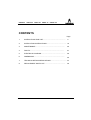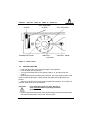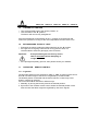
1
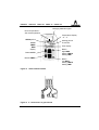
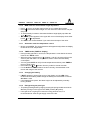
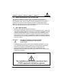
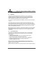
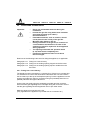
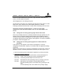
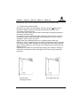
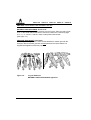
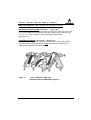
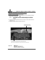
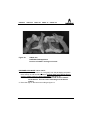
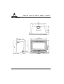
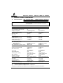
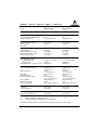
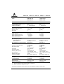
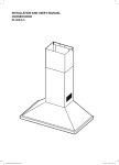
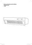
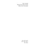
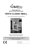
INSTRUCTIONS FOR USE INSTALLATION INSTRUCTIONS UNICA 50 UNICA 52 UNICA 65 UNICA 70 UNICA 100 COUNTRY NATURAL GAS PROPANE GREAT-BRITAIN / IRELAND UNICA 50 NG UNICA 52 NG UNICA 65 NG UNICA 70 NG UNICA 100 NG UNICA 50 PG UNICA 52 PG UNICA 65 PG UNICA 70 PG UNICA 100 PG UNICA 50 UNICA 52 UNICA 65 UNICA 70 UNICA 100 CONTENTS Page 1. INSTRUCTIONS FOR USE...................................................... 2. INSTALLATION INSTRUCTIONS............................................... 16 3. MAINTENANCE...................................................................... 36 4. FAULTS................................................................................. 37 5. ELECTRICAL DIAGRAM......................................................... 38 6. DIMENSIONS......................................................................... 39 7. TECHNICAL DETAILS/REGULATIONS...................................... 44 8. REPLACEMENT PARTS LIST.................................................. 5 48 3 UNICA 100 4 UNICA 70 UNICA 65 UNICA 52 UNICA 50 UNICA 50 UNICA 52 UNICA 65 1 INSTRUCTIONS FOR USE 1.1 INTRODUCTION UNICA 70 UNICA 100 Congratulations on your purchase of this modern BARBAS gas fire. This quality product will provide you with many years of enjoyment due to the flame effect and warmth that it provides. Please read the instructions for use carefully before using the appliance for the first time. Keep this booklet in a safe place. 1.2 BUILT-IN PROTECTION OF THE APPLIANCE The appliance is fully protected by means of a thermo-electric pilot light shut off in the event of a gas escape from the main burner. Additionally, the gas fire is fitted with a thermal one-way protection safety system. This system shuts off the appliance if the flue gas is not exhausted. 1.2.1 Safety Do not place any embers, vermiculite granules or logs against the pilot light burner. Make sure that the pilot flame can burn at all times freely over the main burner. Only in this way is proper ignition of the main burner ensured. Ignoring these directions could lead to a dangerous situation. It is essential that the appliance, the chimney and the burner air intake are cleaned and inspected annually by a recognised fitter/gas specialist. The safe operation of the appliance will thus remain guaranteed. See for additional instructions Chapter 3: Maintenance. If the pilot flame goes out for any reason, wait for 5 minutes before attempting to re-light it. The gas fire must never be used with the door open or the door glass removed. Never place flammable material on the ceramic log set. 5 UNICA 100 UNICA 70 UNICA 65 UNICA 52 UNICA 50 The filling of the main burner with embers, vermiculite granules and wood logs may not under any circumstances be changed or added to. Do not place easily-flammable materials, such as nylon clothing or flammable liquids, in the vicinity of the gas fire. Ensure at all times that children and other people who are not aware of the operation of the gas appliance are only in the vicinity of the appliance exclusively under supervision. Use a fireguard to protect children and other persons mentioned above against possible burns. 1.3 OPERATION : HAND CONTROL The gas regulating block, with which the fire is operated, is located behind the operating hatch. The fire has one main burner which can be operated by the thermostatic knob and/or the sliding knob. The thermostatic knob is used to choose the correct setting and the modulating thermostat ensures that the set temperature (13 - 38°C) is maintained. The slider, is used to select the desired position, the burner will now continueously burn as an atmospheric burner until the setting is changed. Both operating knobs can be used in combination. The Unica 65, Unica 70 and Unica 100 are fitted with a double convection fan as standard. For the Unica 50 and Unica 52 is this an option (factory-done). The fan speed can be regulated with the knob located on the right-hand side of the gas regulating block. The knob on the Unica 52 and 65 can be found by opening the operating hatch on the right hand side. When the appliance reaches a temperature of 40°C, the convection fan will automatically be activated. After the appliance has been switched off, the fan will continue until the temperature has fallen below 35°C. 6 UNICA 50 UNICA 52 UNICA 65 UNICA 70 UNICA 100 “OFF” POSITION SLIDER SLIDER THERMOSTAT KNOB “IGNITION” POSITION “OFF” POSITION “IGNITION” KNOB Figure 1: Hand control 1.4 IGNITING THE FIRE Open the gas supply valve in the gas pipe to the appliance. Lock the slider into “l” position. l Turn the thermostat knob to the ignition position “«” and then push the knob in. l While keeping the thermostat knob pushed in, press the ingition button a few times to ignite the pilot light. Check through the glass that the pilot light has been lit. l When the pilot light is lit, keep the thermostat knob pushed in for a further 10 seconds, after which it can be released. l l Important: l If the pilot flame goes out, then wait for at least 5 minutes before repeating the above procedure. By turning the thermostat knob to the required setting and/or pushing the slider into a downward position: the burner will now ignite. 7 UNICA 100 1.5 l l UNICA 70 UNICA 65 UNICA 52 UNICA 50 TURNING OFF THE FIRE Turn the thermostat knob to the ignition position “«”. Lock the slider to the “l” position. The burner will now be fully extinguished. If the thermostat knob is turned back to the “1” position, then the burner will continue to operate for as long as the room temperature remains below 13°C. 1.6 l l EXTINGUISHING THE PILOT LIGHT Extinguish the pilot by setting the thermostat knob to the “l” position. If the gas fire is not going to be used for a long period of time, it is recommended to close the gas supply valve to the fire. Important: l 1.7 If the pilot flame goes out for any reason, wait for 5 minutes before attempting to re-light it. If the pilot light frequently goes out, then please contact your installer. OPERATION: REMOTE CONTROL 1.7.1 In general The pilot light and burner are switched to “ON “ or “OFF” by means of the control knob A. The flame height of the burner is regulated by control knob B. The desired position is selected and the burner will burn continuously in this position, until this is changed. The control knob B can be used in different ways: 1. Manually, by turning the knob by hand in the desired position. 2. By means of the cordless remote control, where the desired position of the knob and also the flame height are regulated by ultra-sonic signals. 8 UNICA 50 UNICA 52 UNICA 65 B UNICA 70 UNICA 100 A Figure 2: Operating switch 1.7.2 Igniting the fire l l l l l l Open the gas valve in the gas supply pipe to the appliance Turn the control knob B to the position where the “big flame”-symbol is located. Turn the control knob A a little to the left until the stop. Press knob A and keep the button pressed approximately 5 seconds (the gas flows to the pilot light). Continue turning the pressed knob A further to the left to the ignition position (from the « symbol to the “small flame” symbol). A “click” is heard indicating the ignition spark for the pilot light. If necessary, click a few times until the pilot light burns. As soon as the pilot light burns, keep knob A pressed for another 10 seconds, then release. Important: l If the pilot light goes out, then wait for at least 5 minutes before repeating the above mentioned procedure. Continue turning knob A fully to the left until the “ON” position, (the “big flame” symbol) and the main burner is ignited. Beware: it takes a few seconds for the burner to ignite! 9 UNICA 100 UNICA 70 UNICA 65 UNICA 52 UNICA 50 1.7.3 Flame height The flame height of the main burner can now be adjusted by means of control knob B. Manually in approximately 20 steps or by means of the cordless remote control (continuous). Turning knob B to the left in the direction of the “big flame” symbol increases the flame height, to the right in the direction of the l symbol decreases the gas supply from the minimum position to the “OFF” position. 1.7.4 Remote control The remote control operates according to the “ultrasonic” principle and consists of a hand-held transmitter and a reciever. For a correct operation, aim the front of the hand-held transmitter towards the eye of the reciever in the appliance. The appliance must already be switched on with the control knob A. It is recommended to adjust always the flame height to the minimum or “OFF” position, before entirely switching off the appliance with the control knob A. LED indication Battery compartment Figure 3: Reciever 10 UNICA 50 UNICA 52 UNICA 65 UNICA 70 UNICA 100 Changing batteries signal Room temperature / Set roomtemperature Temperature display °C - °F SENDsymbol AUTO TIMER MAN display Button AUTO Button TIMER Heating period P1 and P2 Time display Button High MAN Setting TIMER Setting TIME Button Low MAN Setting TIMER Setting TIME Figure 4: Hand-held transmitter Figure 5: 4 x Connectors to gascontrols 11 UNICA 100 UNICA 70 UNICA 65 UNICA 52 UNICA 50 1.7.5 Extinguishing the fire Turn knob B, possibly with the remote control, fully to the right to the l symbol and/or turn the control knob A to the right until the stop (“small flame” symbol = pilot light position). The main burner will still burn for a few seconds, after which it will be extinguished completely. 1.7.6 Set the display l l l After connecting the batteries or when simultaneously pressing AUTO and TIMER, the display will flash. You are now in “SET” mode. Press AUTO to switch from °F (and standard time) to °C (and military time) or vice versa. The display will automatically return to manual mode after some time, but you may immediately return to MAN by pressing the TIMER button. 1.7.7 Set the current time l l l After connecting the batteries or when simultaneously pressing AUTO and TIMER, the display flashes. You are in SET mode. Press to set the hour and to set the minute. Wait or press TIMER to return to MAN mode. 1.7.8 Programming the desired temperature l l l Press AUTO until display flashes. Press or to set the temperature. Wait or press AUTO to switch to automatic mode. 1.7.9 Programming the timer l l l l l l 12 Press TIMER until P1 flashes (heating period 1, heat ON) Set the time for the beginning of the first heating period by pressing for hour and for minute’setting. Press TIMER again; P1 appears on the display. Set the time for the end of the first heating period. Press TIMER again to set the second heating period P2 (heat ON) and P2 (heat OFF). Store both heating periods by pressing TIMER again. If only one heating period is desired, program the same time for P2 and P1. UNICA 50 1.7.10 l l l l l l l l l l l MAN mode for manual flame height adjustment Automatic mode for temperature control TIMER mode (TIMER in display) Changing the battery If BATT appears in upper right corner of the display or if the LED of the receiver becomes faint, please change the battery from transmitter or receiver. See also 1.7.15 If the batteries lose power, the flame height can be adjusted by manually turning knob B. 1.7.14 l UNICA 100 During heating periods P1 and P2, the temperature is controlled in the same manner as in AUTO mode. When the timer program turns to (heating cycle off), the motor will turn the valve to pilot and there is no temperature control. This minimizes battery consumption. You may press AUTO to verify the set-temperature and then press TIMER to return to timer mode. Press either the or button from any mode for manual override. For the AUTO or TIMER mode to function correctly, the transmitter must remain with range of the receiver. 1.7.13 l UNICA 70 Briefly press AUTO. The set temperature will appear briefly before the display reverts to the room temperature. 1.7.12 l UNICA 65 Press to turn on the fire (main burner) or to increase flame height. Press to decrease flame height or to turn down the main burner. The pilot stays on. To incrementally increase or decrease the flame height lightly tap either the or button. The SEND symbol appears in the upper left corner of the display when either button or is depressed. The LED of the receiver flashes if you reach the end stops of the valve. 1.7.11 l UNICA 52 Extinguishing the pilot light The pilot light extinguishes by slightly pressing the spring loaded control knob A and by turning it to the right to the “OFF” position (l-symbol). If the gas fire is not going to be used for a long period of time, it is recommended to close the gas supply valve to the fire. 13 UNICA 100 Important: 1.7.15 UNICA 70 UNICA 65 UNICA 52 UNICA 50 If the pilot light goes out for any reason, wait for 5 minutes before attempting to re-light it. Replacing the batteries The batteries of the hand-held transmitter and reciever have a lifespan of approximately one year. If BATT appears in upper right corner of the display, please change the battery from the hand-held transmitter. If the LED of the reciever becomes faint, please change the battery from the reciever. Hand-held transmitter: l Open the cover at the back of the hand-held transmitter. l Carefully remove the 9V block battery and release it from the contact maker. Do not pull the wires! l Connect the new battery and refit. Close the cover. Receiver: l Remove the battery support from the housing and release it from the contact holder. l Remove the batteries from the battery support. l Place the 4 new batteries of 1,5V (type LR6 or AA) in the battery support as indicated. The pressure spring always against the negative pole (-) of the battery. Connect the battery support with the contact maker. Replace the support and close the cover. Incorrect placement of the batteries or the battery support can lead to irreparable damage to the electronics or the electric propulsion. NOTE: Please note, the placement of the transmitter (temperature sensor) is important to assure proper temperature regulation. Generally, a more constant temperature will be assured, if the transmitter is not too far from the gas or appliance. Before switching to AUTO or TIMER mode, press either knob to verify the reception (when the SEND symbol appears in the transmitter display, the receiver’s LED must illuminate). 14 UNICA 50 1.8 UNICA 52 UNICA 65 UNICA 70 UNICA 100 USING THE APPLIANCE FOR THE FIRST TIME The gas fire is coated with a lacquer layer resistant to high temperature. During the first hours of operation, the burning in of the lacquer may result in an unpleasant smell. This is harmless, however. Operating the gas fire at full capacity for a few hours, while ventilating the room, will eliminate the smell. Moreover, deposits may form on the inside off the glass; these can be removed with a dry cloth when the gas fire has cooled down. 1.9 l l DAILY MAINTENANCE Regulary check that the air supply is still open. Ensure that as little dust, and as few particles of cigarette smoke, candles and oil lamps as possible pollute the air in the room in which the appliance is used. Heating of these particles by the convection system of the appliance could lead to discoloration of the walls and ceiling. It is therefore very important to ensure that the room in which the appliance is located is sufficiently ventilated. Regularly remove any dust deposits from behind the control flap by means of a vacuum cleaner. Important: l l If the glass is broken or cracked, it must be immediately replaced before operating the gas fire again. If anything is spilt on the fire, switch it off immediately and wait for it to cool down sufficiently before cleaning. Never use scouring powder, aggressive cleaners or fire polish on the gas fire. Use only a dry lint free cloth. Barbas heat resistant lacquer in aerosols can be obtained from your distributor. During the yearly maintenance, the lacquer can be used to repair small areas of damage. IMPORTANT The installation must only be carried out by a CORGI registered installation engineer. 15 UNICA 100 UNICA 70 2 INSTALLATION INSTRUCTIONS 2.1 GENERAL UNICA 65 UNICA 52 UNICA 50 The gas fire must be positioned and connected as a “open” appliance by a CORGI registered installation engineer in accordance with the following installation instructions, nationally and locally applicable regulations (see “Technical Details/ Regulations” at the rear of this manual). If you have any queries regarding the installation, please consult your local gas company. If an existing chimney is to be used, please consult your installer first. If the chimney was previously used for a wood or coal fire, then it should be cleaned by an expert. A chimney draw of approximately 5 Pa (=0,05 mbar) is sufficient for full load of the appliance. If the chimney draw is more than 20 Pa (=0,2 mbar), then it is recommended to reduce it. Before beginning the installation, check that the details on the rating plate correspond to the gas type and pressure to which the appliance will be connected. 2.2 FLUE PROTECTION The appliance is supplied with a security system T.T.B. It is a thermostat which shuts off the pilot light and main burner under any of the following circumstances: l insufficient chimney draw. l under-pressure in the house due to a mechanical exhaust system. l bad connection between the appliance and the flue. l partial or total blockage of the flue, for instance, due to falling debris. l insufficient external air supply in an entirely closed house. l flue down draught due to wind. After the problem has been rectified, the appliance can be put back into operation. It is not permitted to bypass the security system. Always call your installer in case of any problem. Replace the security system only with parts identical to those originally supplied! 16 UNICA 50 2.3 UNICA 52 UNICA 65 UNICA 70 UNICA 100 PREPARATIONS BEFORE INSTALLATION Before installing the appliance, first observe the following instructions. 2.3.1 The most important facilities according to the regulations: 1 NATURALLY VENTILATED HOUSE (see Figure 6). l l The room in which the appliance is to be fitted must have a nonclosable combustion air supply opening. The minimum dimensions are detailed in “Technical Details/Regulations” at the rear of this manual (see also Paragraph 2.4, point 4). The flue gas exhaust must exit at “outlet area I”. OUTLET AREA I AIR SUPPLY OPENING GAS Figure 6: Naturally ventilated house 17 UNICA 100 UNICA 70 UNICA 65 UNICA 52 UNICA 50 2 MECHANICALLY VENTILATED HOUSE (see Figure 7) l l The room in which the appliance is to be fitted must have a nonclosable combustion air supply opening. The minimum dimensions are detailed in “Technical Details/Regulations” at the rear of this manual (see also Paragraph 2.4, point 4). The flue gases must be extracted by means of a flue extraction fan. FLUE EXTRACTION FAN GAS Figure 7: Mechanically ventilated house 18 AIR SUPPLY OPENING UNICA 50 UNICA 52 UNICA 65 UNICA 70 UNICA 100 2.4 GENERAL SERVICES 1. UNPACKING THE APPLIANCE The appliance is fitted with two “carrying handles” at the top. If required, they may be removed during installation. 2. FRAME The appliance is fitted with a 20 mm wide frame as standard. A detachable 50 mm (Unica 50: 32 mm) wide frame is placed on top. 3. FLUE Before installation, it must be verified that the flue has sufficient draw. Remove all flue gas dampers (if present) in the flue or fix them in the open position. The flue must be at least 2 metres long. In order to prevent condensation in a masonry flue and, if necessary, to improve correct operation of the appliance, it is recommended that the flue be fitted with an, (isolated) aluminium or (flexible) stainless steel pipe of Ø100 mm (minimum). An protective cap must be placed on top of the chimney to prevent rain entering. 4. COMBUSTION AIR SUPPLY The combustion air supply has to comply with national and local regulations. The minimum dimensions are detailed in “Technical Details/ Regulations” at the rear of this manual. The air supply opening must be non-closable. 5. THERMOSTAT SENSOR The appliance is equipped with a thermostat sensor which is normally fitted to the bottom plate. The thermostat function can be improved by positioning the sensor in the bottom left- or right hand side, or at the height of the plinth underneath the appliance. Ensure that the sensor remains easily accessible at all times for service and maintenance. 6. GAS CONNECTION The Ø12 mm or Ø15 mm gas connection is located on the left side of the appliance. Connect the gas supply to the appliance using the push coupling. Use only gas piping with a minimum diameter of 1/2” G with a shut-off valve. 7. ELECTRICAL CONNECTION If the appliance is equipped with a convection fan, there must be a wall socket with earth connection, preferably at the right-hand side of the appliance. The socket should be accessible at all times. 19 UNICA 100 2.5 UNICA 70 UNICA 65 UNICA 52 UNICA 50 POSITIONING THE APPLIANCE Important: l l l l l l Never use combustible materials during the installation. Insulate the gas fire using white loose insulation wool (heat resistant up to 1000°C). Not at the bottom !! Flammable materials, such as curtains, should not be placed in the vicinity of the gas fire. Minimum safe distance: 100 cm. During installation of the gas fire, a clearance of 3 mm should be maintained on all sides of the appliance to allow for expansion of the appliance during operation. The opening underneath the operation hatch (2 cm) must remain completely free. Position the appliance at least 12 cm above the floor height. Read one of the following instructions for fitting the appliance, as applicable: Paragraph 2.5.1 Fitting into a new chimney Paragraph 2.5.2 Fitting into an existing opening larger than the fire insert Paragraph 2.5.3 Fitting into an existing opening equal or smaller than the fire insert. 2.5.1 Fitting into a new chimney The fireplace must be mounted on a concrete floor. If there is no concrete floor, it is essential to re-enforce the floorboards underneath with concrete. Build in the fire insert up to the top of the fireplace opening. Push the appliance into the opening and make the chimney connection using an (insulated) aluminium or (flexible) stainless steel pipe of Ø100 mm. Connect the gas supply using the separately provided gas inlet connector. Ensure that the gas regulating block is straight during the connection. Ensure that the gas regulating block and pipework are not put under stress. Make the electrical connection to the fan. (Only applicable if the appliance is provided with an convection fan.) 20 UNICA 50 UNICA 52 UNICA 65 UNICA 70 UNICA 100 Position the thermostat sensor at the left-or right hand side underneath the frame, or at the height of the plinth. See Paragraphe 2.5.3 for fitting the log set. Check that all connections are completely gas tight using soapy water or a leak tester. As a check, allow the fire to burn briefly (maximum 1 minute). Following verification that there are no leaks, finish off building in the fire insert. MASONRY REQUIRES APPROXIMATELY 4 WEEKS TO BECOME COMPLETELY DRY BEFORE NORMAL USE OF THE FIRE INSERT CAN BEGIN. 2.5.2 Fitting into an existing opening larger than the fire insert. Place an (insulated) aluminium or (flexible) stainless steel pipe (Ø100 mm) into the flue for the connection between the flue spigot of the appliance and the chimney and then position the appliance into the fireplace. Push the aluminium or stainless steel pipe into the flue spigot of the appliance. For further installation procedures, refer to Paragraph 2.5.1. 2.5.3 Fitting into an existing opening equal to or smaller than the fire insert. If the opening in the fireplace is too small for the appliance, it must be enlarged by an authorised company in accordance with the applicable building regulations. Before fitting the fire insert, a number of preparations must be made. Firstly, the appliance must be completely dismanteld, as follows (see also Figure 8 or 9): 1. Open the operating hatch underneath the appliance by pulling it forwards. 2. Dismantling operating hatch(es): Unica 50 : The operating hatch can be taken out if the left hinge pin is Unica 70 pulled from the frame by means of pointed pliers, or Unica 100 unscrewing the left Phillips screw if there is one. Unica 52 : Unica 65 Dismantle the centre operating hatch by pushing it to the left, after which it can be taken out at the right-hand side. The right operating hatch can be taken out by pushing it to the right. The left operating hatch can be taken out by lifting it slighty. 21 UNICA 100 UNICA 70 UNICA 65 UNICA 52 UNICA 50 3. Dismantling the frame: When necessary, the 50 mm frame can be removed (Unica 50: 32 mm). Unica 50 : Loosen the screws underneath at the left-and right hand side, Unica 70 at the inside of the frame, and remove the frame by pulling it Unica 100 forwards. Unica 52 : Unica 65 Push the frame upwards and remove it. 4. Dismantling the front, door and glass: Unica 50 : Remove the door by carefully pulling it forwards at the bottom Unica 70 and subsequently lift it slightly. The entire door can be taken Unica 100 out from the front. Remove the glass plate by lifting the glass clips using a screw-driver. Unica 52 : Unica 65 Dismantle the door (including the glass) by loosening the screws at the top and bottom. Dismantle the front by loosening all screws around the door opening. Wear protective gloves when handling the glass. 5. Carefully remove the log set. 6. Dismantle the glass support plate at the front in the combustion chamber, by loosening the 4 bolts and by removing the glass support plate. 7. Disconnect the (light blue) plug connectors of the security system wiring. 8. The complete “control unit” can now be slid out like a drawer. 9. Dismantling the inner shell: Unica 50 : Dismantle the entire inner shell by completely loosening a nut Unica 70 at the left-and right hand side bottom, after which the inner Unica 100 shell will turn over by its own weight at the bottom. The complete inner shell can be removed by lifting it from its hinge points. 22 UNICA 50 UNICA 52 Unica 52 : Unica 65 UNICA 65 UNICA 70 UNICA 100 Dismantle the entire inner shell by slightly loosening the 4 nuts at the front. Next, turn the adjustment bolt downwards at the left-and right hand side bottom which slightly lowers the inner shell compared to the outer casing. The inner shell can be removed after loosening the 4 insert nuts. Flue spigot Outer casing 50 mm Frame (Unica 50: 32 mm Frame) Inner shell Control unit Glass support plate Operating hatch Door Figure 8: Unica 50 / Unica 70 / Unica 100 23 UNICA 100 UNICA 70 UNICA 65 UNICA 52 UNICA 50 Flue spigot Outer casing Inner shell Control unit Glass support plate Front Operating hatch 50 mm Frame Door Figure 9: Unica 52 / Unica 65 10. The flue spigot can be removed by loosening the self-tapping screws from the inside of the outer casing. The appliance is now fully dismantled. 24 UNICA 50 UNICA 52 UNICA 65 UNICA 70 UNICA 100 Installing the gas fire insert should be carried out in the following order: 1. FITTING THE OUTER CASING Place the outer casing into the fireplace opening. Using the supplied frame, position the fireplace casing horizontally and vertically level to the wall. The casing must also be level. Check that the gas supply pipe has been fed through the opening provided at the bottom left-hand corner. If necessary, loosen the electrical supply cable from the connector, and guide the cable through the special openings to the wall socket, on which, during installation, there must be no tension. Slightly lower the (insulated) aluminium or (flexible) stainles steel pipe (Ø100 mm), which is made through the chimney, through the opening at the top of the outer casing. Attach the pipe to the flue spigot and push it back upwards again. The flue spigot can now be fixed to the casing from the inside using self tapping screws. If required, it is possible to fix the flue spigot sloping to the back by drilling out blind rivets, turning the aluminium flue spigot 180° and securing it again with pop-rivets. Factory-done: Flue spigot vertical Flue spigot under 65° 25 UNICA 100 UNICA 70 UNICA 65 UNICA 52 UNICA 50 2. FITTING THE INNER SHELL Before assembly, check that the sealing cords of the flue spigot and glass are still intact. Unica 50 : Hook the complete inner shell onto the hinge points at the top Unica 70 left and right hand corner of the casing. Tilt the inner shell Unica 100 backwards and secure it with two nuts. Unica 52 : Unica 65 Position the complete inner shell in the casing. Position the inner shell by, first of all, fitting loosely the 4 insert nuts, so that the inner shell is completely level against the front of the outer casing. Next, adjust the inner shell by means of adjustment bolts which are located on the bottom left and right of the combustion chamber. The flue spigot of the inner shell has to be tightly fitted against the top side of the outer casing. Tighten all 4 insert nuts securely. CHECK THAT THE SEALING CORD OF THE FLUE SPIGOT IS CORRECTLY CONNECTED ! 3. FITTING THE “CONTROL UNIT” First of all, make the elctrical connection (when dismantled) on the connector on the right-hand side. (Only applicable if the appliance is provided with a convection fan.) While sliding the “control unit” underneath the inner shell, secure the (light blue) plug connectors of the security system. For this purpose, the wires need to be led outside, left along the inner shell, after which the plugs have to be pushed on the thermocouple interrupter near the gas regulating block. The “control unit” must be pushed into the inner shell as far as it will go. Fit the thermostat sensor by means of the clip to the bottom plate. Use 4 bolts to secure the “control unit” together with the glass support plate. 4. GAS AND ELECTRICAL CONNECTION Use the supplied swivel to make the gas connection. Ensure that the gas regulating block stays straight during the connection. Ensure that the gas regulating block and pipework are not put under stress. 26 UNICA 50 UNICA 52 UNICA 65 UNICA 70 UNICA 100 The mains electricity can now be restored to the wall socket. (Only applicable if the appliance is provided with a convection fan.) Check that all connections are completely gas tight using soapy water or a leak tester. As a check, allow the fire to burn briefly (maximum 1 minute). Following verification that there are no leaks, finish off building in the fire insert. (See Chapter 1; Instructions for use.) 5 POSITIONING THE CERAMIC LOG SET The appliance is delivered with a set of artificial wooden logs and vermiculite (and/or embers: Unica 50 and Unica 100). Important: • • • Do not place any vermiculite granules, embers or logs against the pilot light burner. Make sure that the pilot flame can burn at all times freely over the main burner. Only in this way is proper ignition of the main burner ensured. The burner bed (with embers and/or vermiculite granules) and the positioning of the logs must not be changed. Ignoring these directions could lead to a dangerous situation. 27 UNICA 100 UNICA 70 UNICA 65 UNICA 52 UNICA 50 UNICA 50: POSITIONING THE CERAMIC LOG SET: NATURAL GAS-APPLIANCE: Unica 50 N... 1. Carefully remove the embers (1x 125 gram) from the packaging and place them evenly on and around the burner. Note ! Small embers and their residue should not be scattered on the burner. This can cause a blockage on the burner orifices. 2. Distribute the vermiculite granules (1x 5 gram) evenly over the burner. 3. Place the logs on the burner according to figure 10. Pilot light Embers Vermiculite granules Embers and vermiculite granules must not be placed next to the pilot light burner. Make sure that the pilot flame can burn freely over the main burner. Figure 10: 28 Log set UNICA 50 NATURAL GAS-appliance Position of embers, vermiculite granules and logs on burner UNICA 50 UNICA 52 UNICA 65 UNICA 70 UNICA 100 PROPANE-APPLIANCE: Unica 50 P... 1. Carefully remove the embers (1x 125 gram) from the packaging and place them evenly on and around the burner (not on the holes!). Please make sure that all burner orifices (small holes) are kept unblocked ! Note ! Small embers and their residue should not be scattered on the burner. This can cause a blockage on the burner orifices. 2. Place the logs on the burner according to figure 11. Pilot light Embers Embers must not be placed on the burner holes. Embers must not be placed next to the pilot light burner. Make sure that the pilot flame can burn freely over the main burner. Figure 11: Log set UNICA 50 PROPANE-appliance Position of embers and logs on burner 29 UNICA 100 UNICA 70 UNICA 65 UNICA 52 UNICA 50 UNICA 52: POSITIONING THE CERAMIC LOG SET: NATURAL GAS-APPLIANCE: Unica 52 N... Evenly distribute the vermiculite granules over the burner. Place the rear log set; no , in the holder behind the burner. After that, position the 5 remaining logs; no , ‚ , and , with the “sharp” sides pointed downwards. (See figure 12.) PROPANE-APPLIANCE: Unica 52 P... Positioning of the log set is the same as that detailed for natural gas with the exception that vermiculite granules are not permitted and are therefore not supplied with appliances that use propane. Figure 12: 30 Log set UNICA 52 NATURAL GAS and PROPANE- appliance UNICA 50 UNICA 52 UNICA 65 UNICA 70 UNICA 100 UNICA 65 / UNICA 70: POSITIONING THE CERAMIC LOG SET: NATURAL GAS-APPLIANCE: Unica 65 N... / Unica 70 N... Evenly distribute the vermiculite granules over the burner. Place the rear log set; no , in the holder behind the burner. After that, position the 5 remaining logs; no , ‚ , and , with the “sharp” sides pointed downwards. (See figure 13.) PROPANE-APPLIANCE: Unica 65 P... / Unica 70 P... Positioning of the log set is the same as that detailed for natural gas with the exception that vermiculite granules are not permitted and are therefore not supplied with appliances that use propane. Figure 13: Log set UNICA 65 / UNICA 70 NATURAL GAS and PROPANE- appliance 31 UNICA 100 UNICA 70 UNICA 65 UNICA 52 UNICA 50 UNICA 100: POSITIONING THE CERAMIC LOG SET: NATURAL GAS-APPLIANCE: Unica 100 N... 1. Carefully remove the embers (2 x125 gram) from the packaging and place them evenly on the burner. Note ! Small embers and their residue should not be scattered on the burner. This can cause a blockage on the burner orifices. 2. Place the two rear logs behind the burner with the carbon side to the front. (See figure 14.) 3. Place the remaining logs according to figure 15. Positioning the rear logs The carbon side to the top Embers must not be placed next to the pilot light burner. Make sure that the pilot flame can burn freely over the main burner. Figure 14: 32 UNICA 100 NATURAL GAS-appliance Position of embers on burner UNICA 50 Figure 15: UNICA 52 UNICA 65 UNICA 70 UNICA 100 UNICA 100 NATURAL GAS-appliance Position of embers and logs on burner PROPANE-APPLIANCE: Unica 100 P... 1. Carefully remove the embers (1 x125 gram) from the packaging and place them evenly on and around the burner. Please make sure that all burner orifices (small holes) are kept unblocked ! See figure 16. Note ! Small embers and their residue should not be scattered on the burner. This can cause a blockage on the burner orifices. 2. Place the logs on the burner according to figure 17. 33 UNICA 100 UNICA 70 UNICA 65 UNICA 52 UNICA 50 Positioning the rear logs The carbon side to the top Embers must not be placed on the burner holes. Embers must not be placed next to the pilot light burner. Make sure that the pilot flame can burn freely over the main burner. Figure 16: UNICA 100 PROPANE-appliance Position of embers on burner Figure 17: UNICA 100 PROPANE-appliance Position of embers and logs on burner 34 UNICA 50 6. UNICA 52 UNICA 65 UNICA 70 UNICA 100 FITTING THE FRONT, DOOR AND GLASS (WEAR PROTECTIVE GLOVES !!!) Unica 50 : or Unica 70 Unica 100 First position the glass into the glass support plate at the bottom the combustion chamber. Push the glass against the cord and clip it on with three glass clips at the top. CHECK THAT THE GLASS CONNECTS PROPERLY WITH THE CORD. Position the door by hooking in at the left and right top side and by pushing in at the bottom. Unica 52 : Unica 65 First of all, check that the sealing cord on the front side of the combustion chamber is still intact. After that, screw the front on the combustion chamber. After verification of the sealing cord in the door, the door can be screwed to the front. 7. FITTING THE OPERATING HATCH(ES) Unica 50: Unica 70 Unica 100 Fit the operating hatch on the right-hand side of the opening. Press the left hinge pin and position the hatch in the correct position or tighten the left Phillips screw if there is one. Unica 52 : Unica 65 Fit the centre operating hatch by pushing it to the left in the opening, after which it can be positioned at the right-hand side. Push the right operating hatch to the right in the opening and position at the left-hand side. Hook the left operating hatch in the front. THE APPLIANCE IS NOW READY FOR USE. 2.6 CHECKING THE APPLIANCE AFTER INSTALLATION After installation, the installer needs to visually check the gas flames. The installer should also verify, by using the appliance for the first time, after 10 minutes of operation, that there is no flue leakage. 35 UNICA 100 3 MAINTENANCE 3.1 ANNUAL MAINTENANCE UNICA 70 UNICA 65 UNICA 52 UNICA 50 It is essential that the appliance, the chimney and the burner air intake are cleaned and inspected annually by a recognised fitter/gas specialist. The safe operation of the appliance will thus remain guaranteed. Maintenance consists of the following: l l l l l l l l l 36 Remove first the embers and/or vermiculite granules and set of logs from the main burner and carefully clean these with a soft brush. Clean and inspect (visually) the main burner(s), pilot light, combustion chamber, flue system and combustion air intake. Dust can be removed using a vacuum cleaner. After cleaning; Carefully replace the embers and/or vermiculite granules and set of logs on and around the main burner according to the installation directions in this instruction booklet. Do not place any embers, vermiculite granules or logs against the pilot light burner. Make sure that the pilot flame can burn at all times freely over the main burner. Only in this way is proper ignition of the main burner ensured. Ignoring these directions could lead to a dangerous situation. Check the gas supply and flue pipe/chimney for any leaks. Check the correct operation of the gas regulation block, thermocouple circuit and the ignition of the main burner. Check the gas inlet-pressure (both when the appliance is off and when it burns at maximum) and the burner pressure. Check the complete flue pipe/chimney, including the outlet on the roof. Check the operation of the thermostatically controlled convection fans. (if present.) Check the operation of the thermal one-way protection safety system. UNICA 50 4 UNICA 52 UNICA 65 UNICA 70 UNICA 100 FAULTS Possible reasons for the gas fire going out are: l l l l l l Operation of the thermal one-way protection safety system due to flue gas escape. Malfunction of the thermal one-way protection safety system. Check by means of testing. Insufficient gas pressure. Pilot light is dirty. Thermocouple voltage too low. This is usually caused by insufficient heating at the tip of the thermocouple by the pilot light. Dirty electrical contacts in the thermo-electric system, wiring and connections of the thermal one-way protection safety system. 37 UNICA 100 UNICA 65 UNICA 52 ELECTRICAL DIAGRAM brown blue yellow/green 5 UNICA 70 brown blue yellow/green brown brown 1 2 3 4 5 6 7 38 Fanspeed controller convection-fan 230 VAC / 50 Hz Convection-fan 230 VAC / 50 Hz Thermostat “Clickson” set at ± 40° C Earthed plug (with earth sleeve) 230 VAC Cabel clamp Connector Earth connector UNICA 50 UNICA 50 UNICA 52 6 DIMENSIONS 6.1 UNICA 50 UNICA 65 UNICA 70 UNICA 100 Gas connection 39 UNICA 100 6.2 UNICA 70 UNICA 65 UNICA 52 UNICA 50 UNICA 52 525 (fixed frame) (fixed frame) Gas connection 40 UNICA 50 UNICA 65 UNICA 70 UNICA 100 UNICA 65 (fixed frame) (fixed frame) 6.3 UNICA 52 Gas connection 41 UNICA 100 6.4 UNICA 70 UNICA 65 UNICA 52 UNICA 50 UNICA 70 (fixed frame) (fixed frame) Gas connection 42 Plateau UNICA 50 UNICA 65 UNICA 70 UNICA 100 UNICA 100 (fixed frame) (fixed frame) 6.5 UNICA 52 Gas connection 43 UNICA 100 7 UNICA 70 UNICA 65 UNICA 52 UNICA 50 TECHNICAL DETAILS / REGULATIONS 7.1 Technical details; NG; NATURAL GAS - GREAT BRITAIN / IRELAND PG; PROPANE - GREAT BRITAIN / IRELAND National Installation Regulations: Gas safety installation and use regulations 1984 plus all relevant safety and building regulations concerning fire installations Model : UNICA 50 NG : UNICA 50 PG Country : GB; Great Britain / IE; Ireland : GB; Great Britain / IE; Ireland Product identification no Type of appliance under CE-norm Category of appliance : 0063 AU 3899 : B11BS : I2H, natural gas G20 : 0063 AU 3899 : B11BS : I3P, propane G31 Nominal heat input (nett calorific value) Nominal heat output (max.) Efficiency class NOx class : 6.4 kW : 5.5 - 6.0 kW : 2 (80%) :1 : 6.2 kW : 4.6 - 5.2 kW : 2 (80%) :1 Gas rate (max.) Supply pressure Burner pressure (max.) Hot Burner pressure (max.) Cold Burner pressure (min.) : 0.68 m3s/hr. : 20.0 mbar : 12.0 mbar(*) : 11.0 mbar(**) : 2.5 mbar : 480 gr/hr. : 37.0 mbar : 29.0 mbar : 29.0 mbar : 5.0 mbar Gas regulator block (hand control) Min. heatinput adj. screw: - Thermostatic burner - Manual burner Gas regulator block (remote control) : SIT 0.630.704 : SIT 0.630.704 : no 160 (= Ø1.60 mm) : standard : Mertik GV 34 : no 100 (= Ø1.00 mm) : standard : Mertik GV 34 Main burner Primary air inlet main burner : Barbas 242 x 122 (2 row) : 8x Ø8.5 mm Gas connection Necessary air supply Chimney connection : Barbas 242 x 122 (2 row) : 1x Ø8.5 mm + 2x Ø6.5 mm : no 90 (= 7x Ø0.90 mm) : SIT 0.160.022 : no 41 : Thermodisc type: 44T21-316128 -120°C : 3/8” G / Ø12 mm : 40 cm2 : Ø100 - Ø106 - Ø125 mm Batteries remote control - Receiver - Hand-transmitter : 4x 1.5V AA : 1x 9V block : 4x 1.5V AA : 1x 9V block Electrical supply (***) Electricity consumption (***) : 230 VAC / 50 Hz : 40 W / IP 20 : 230 VAC / 50 Hz : 40 W / IP 20 Main burner orifice Pilot burner Pilot burner orifice Security system (T.T.B.) : no 140 (= 1x Ø1.40 mm) : SIT 0.160.022 : no 30 : Thermodisc type: 44T21-316128 -120°C : 3/8” G / Ø12 mm : 40 cm2 : Ø100 - Ø106 - Ø125 mm (*) : When the appliance has reached its thermal equilibrium. (**) : Burner at maximum. Appliance is cold. (***) : When the appliance is equipped with a convection fan. Temperature changes at surface: Entire front of the appliance, except the control panel. 44 UNICA 50 UNICA 52 UNICA 65 UNICA 70 UNICA 100 Model : UNICA 52 NG Country : GB; Great Britain / IE; Ireland : GB; Great Britain / IE; Ireland Product identification no Type of appliance under CE-norm Category of appliance : 0063 AU 3899 : B11BS : I2H, natural gas G20 : 0063 AU 3899 : B11BS : I3P, propane G31 Nominal heat input (nett calorific value) Nominal heat output (max.) Efficiency class NOx class : 6.9 kW : 5.5 - 6.0 kW : 2 (80%) :1 : 5.9 kW : 4.7 - 5.0 kW : 2 (80%) :1 Gas rate (max.) Supply pressure Burner pressure (max.) Hot Burner pressure (max.) Cold Burner pressure (min.) : 0.72 m3s/hr. : 20.0 mbar : 14.6 mbar(*) : 14.1 mbar(**) : 3.8 mbar : 460 gr/hr. : 37.0 mbar : 29.0 mbar : 29.0 mbar : 6.0 mbar Gas regulator block (hand control) Min. heatinput adj. screw: - Thermostatic burner - Manual burner Gas regulator block (remote control) : SIT 0.630.704 : SIT 0.630.704 : no 160 (= Ø1.60 mm) : standard : Mertik GV 34 : no 100 (= Ø1.00 mm) : standard : Mertik GV 34 Main burner Primary air inlet main burner Gas connection Necessary air supply Chimney connection : Barbas 242 x 122 (2 row) : 2x Ø8.5 mm + 1x Ø6.5 mm : no 90 (= 7x Ø0.90 mm) : SIT 0.160.022 : no 41 : Thermodisc type: 44T21-316128 -120°C : 3/8” G / Ø12 mm : 40 cm2 : Ø100 - Ø106 - Ø125 mm : Barbas 242 x 122 (2 row) : 4x Ø8.5 mm + 3x Ø6.5 mm : no 140 (= 1x Ø1.40 mm) : SIT 0.160.022 : no 30 : Thermodisc type: 44T21-316128 -120°C : 3/8” G / Ø12 mm : 40 cm2 : Ø100 - Ø106 - Ø125 mm Batteries remote control - Receiver - Hand-transmitter : 4x 1.5V AA : 1x 9V block : 4x 1.5V AA : 1x 9V block Electrical supply (***) Electricity consumption (***) : 230 VAC / 50 Hz : 40 W / IP 20 : 230 VAC / 50 Hz : 40 W / IP 20 Main burner orifice Pilot burner Pilot burner orifice Security system (T.T.B.) (*) : (**) : (***) : : UNICA 52 PG When the appliance has reached its thermal equilibrium. Burner at maximum. Appliance is cold. When the appliance is equipped with a convection fan. Temperature changes at surface: Entire front of the appliance, except the control panel. 45 UNICA 100 UNICA 70 UNICA 65 UNICA 52 UNICA 50 Model :UNICA 65 NG UNICA 70 NG Country : GB; Great Britain / IE; Ireland : GB; Great Britain / IE; Ireland Product identification no Type of appliance under CE-norm Category of appliance : 0063 AU 3899 : B11BS : I2H, natural gas G20 : 0063 AU 3899 : B11BS : I3P, propane G31 Nominal heat input (nett calorific value) Nominal heat output (max.) Efficiency class NOx class : 8.6 kW : 7.0 - 8.0 kW : 2 (80%) :1 : 7.9 kW : 6.3 - 7.0 kW : 2 (80%) :1 Gas rate (max.) Supply pressure Burner pressure (max.) Hot Burner pressure (max.) Cold Burner pressure (min.) : 0.91 m3s/hr. : 20.0 mbar : 10.0 mbar(*) : 9.0 mbar(**) : 2.0 mbar : 615 gr/hr. : 37.0 mbar : 29.0 mbar : 29.0 mbar : 7.5 mbar Gas regulator block (hand control) Min. heatinput adj. screw: - Thermostatic burner - Manual burner Gas regulator block (remote control) : SIT 0.630.704 : SIT 0.630.704 : no 160 (= Ø1.60 mm) : standard : Mertik GV 34 : no 130 (= Ø1.30 mm) : standard : Mertik GV 34 Main burner Primary air inlet main burner Gas connection Necessary air supply Chimney connection : Barbas 360 x 122 (2 row) : 4x Ø8.5 mm + 2x Ø6.5 mm : no 115 (= 7x Ø1.15 mm) : SIT 0.160.022 : no 41 : Thermodisc type: 44T21-316190 -140°C : 3/8” G / Ø12 mm - Ø15 mm : 50 cm2 : Ø100 - Ø106 - Ø125 mm : Barbas 360 x 122 (2 row) : 4x Ø8.5 mm + 4x Ø6.5 mm : no 160 (= 1x Ø1.60 mm) : SIT 0.160.022 : no 30 : Thermodisc type: 44T21-316190 -140°C : 3/8” G / Ø12 mm - Ø15 mm : 50 cm2 : Ø100 - Ø106 - Ø125 mm Batteries remote control - Receiver - Hand-transmitter : 4x 1.5V AA : 1x 9V block : 4x 1.5V AA : 1x 9V block Electrical supply Electricity consumption : 230 VAC / 50 Hz : 40 W / IP 20 : 230 VAC / 50 Hz : 40 W / IP 20 Main burner orifice Pilot burner Pilot burner orifice Security system (T.T.B.) :UNICA 65 PG UNICA 70 PG (*) : When the appliance has reached its thermal equilibrium. (**) : Burner at maximum. Appliance is cold. Temperature changes at surface: Entire front of the appliance, except the control panel. 46 UNICA 50 UNICA 52 UNICA 65 UNICA 70 UNICA 100 Model : UNICA 100 NG Country : GB; Great Britain / IE; Ireland : GB; Great Britain / IE; Ireland Product identification no Type of appliance under CE-norm Category of appliance : 0063 AU 3899 : B11BS : I2H, natural gas G20 : 0063 AU 3899 : B11BS : I3P, propane G31 Nominal heat input (nett calorific value) Nominal heat output (max.) Efficiency class NOx class : 10.5 kW : 8.0 - 9.0 kW : 2 (80%) :1 : 8.4 kW : 6.3 - 7.0 kW : 2 (80%) :1 Gas rate (max.) Supply pressure Burner pressure (max.) Hot Burner pressure (max.) Cold Burner pressure (min.) : 1.10 m3s/hr. : 20.0 mbar : 10.0 mbar(*) : 9.0 mbar(**) : 2.0 mbar : 650 gr/hr. : 37.0 mbar : 29.0 mbar : 29.0 mbar : 7.5 mbar Gas regulator block (hand control) Min. heatinput adj. screw: - Thermostatic burner - Manual burner Gas regulator block (remote control) : SIT 0.630.704 : SIT 0.630.704 : no 160 (= Ø1.60 mm) : standard : Mertik GV 34 : no 130 (= Ø1.30 mm) : standard : Mertik GV 34 Main burner Primary air inlet main burner : Barbas 360x122 (2 row) HZ : 8x Ø8.5 mm Gas connection Necessary air supply Chimney connection : Barbas 360x122 (2 row) HZ : 4x Ø8.5 mm + 2x Ø6.5 mm : no 320 (= 1x Ø3.20 mm) : SIT 0.160.022 : no 51 : Thermodisc type: 44T21-316190 -140°C : 3/8” G / Ø12 mm - Ø15 mm : 60 cm2 : Ø100 - Ø106 - Ø125 mm Batteries remote control - Receiver - Hand-transmitter : 4x 1.5V AA : 1x 9V block : 4x 1.5V AA : 1x 9V block Electrical supply Electricity consumption : 230 VAC / 50 Hz : 40 W / IP 20 : 230 VAC / 50 Hz : 40 W / IP 20 Main burner orifice Pilot burner Pilot burner orifice Security system (T.T.B.) : UNICA 100 PG : no 160 (= 1x Ø1.60 mm) : SIT 0.160.022 : no 30 : Thermodisc type: 44T21-316190 -140°C : 3/8” G / Ø12 mm - Ø15 mm : 60 cm2 : Ø100 - Ø106 - Ø125 mm (*) : When the appliance has reached its thermal equilibrium. (**) : Burner at maximum. Appliance is cold. Temperature changes at surface: Entire front of the appliance, except the control panel. 47 UNICA 100 8 UNICA 70 UNICA 65 UNICA 52 UNICA 50 REPLACEMENT PARTS LIST When requesting service or ordering replacement parts, please quote the model type and serial number. All parts listed in this manual may be ordered from a Barbas dealer. 8.1 UNICA 50 No Part no Description 1 2 3 4 5 302056 301965 302037 302041 301969 Gas regulator block, EuroSIT Plus 0.630.704 Piezo push-button Minimal heatinput adj. screw 1.6 mm; natural gas Minimal heatinput adj. screw 1.0 mm; propane Nut + olive; Ø4 mm 6 7 8 9 302408 302409 302410 302411 Gas regulator block, Mertik GV 34 Hand-held transmitter (remote control) Receiver with cable Cable 10 Main burner natural gas G20 X X Main burner propane G31 X X 12 13 305966 1xØ8,5+2xØ6,5 305967 8xØ8,5 301927 301937 Main burner injector natural gas; no 90 Main burner injector propane; no 140 X X X X 14 15 16 17 18 19 20 21 22 302059 301207 301976 301977 302070 302060 301921 302053 301887 Pilot light set outer casing; SIT 0.160.022 Pilot light pipe; Ø4 mm; l = 340 mm Pilot light olive; Ø4 mm Pilot light nut; Ø4 mm Pilot light electrode + cable; l = 500 mm Pilot light injector, natural gas; no 41 Pilot light injector, propane; no 30 Thermocouple M10 - 600 mm - th.c.i. Security system T.T.B. 120°C X X X X X X X X X X X X X X X X X X 23 322133 Glass Unica 50; 483 x 321 x 4 mm X X 24 25 26 302156 302173 302154 Convection fan 230 VAC / 50 Hz. Fanspeed controller 230 VAC / 50 Hz. Clickson X X X X X X 11 48 Hand control Remote control X X X X X X X X X UNICA 50 UNICA 52 UNICA 65 No Part no Description 27 28 29 30 31 301617 301595 301592 301607 301614 32 33 34 301669 322372 301863 35 301839 UNICA 70 UNICA 100 Hand control Remote control Black fibre glass cord Ø10 mm; l = 2000 mm Fibre glass tape 20 x 6 mm; l = 360 mm Fibre glass tape 15 x 3 mm; l = 1300 mm Black fibre glass cord Ø6 mm; l = 1950 mm Black fibre glass tape 10x2 mm; l = 290 mm X X X X X X X X X X Tube ceramic glue Log set Unica 50, natural gas and propane; 5-parts Embers (125 gram) natural gas and propane; 1x 125 gram Vermiculite granules (± 5 gram) natural gas X X X X X X X X 49 UNICA 100 8.2 UNICA 70 UNICA 65 UNICA 52 UNICA 50 UNICA 52 No Part no Description 1 2 3 4 5 302056 301965 302037 302041 301969 Gas regulator block, EuroSIT Plus 0.630.704 Piezo push-button Minimal heatinput adj. screw 1.6 mm; natural gas Minimal heatinput adj. screw 1.0 mm; propane Nut + olive; Ø4 mm 6 7 8 9 302408 302409 302410 302411 Gas regulator block, Mertik GV 34 Hand-held transmitter (remote control) Receiver with cable Cable 10 Main burner natural gas G20 X X Main burner propane G31 X X 12 13 305966 2xØ8,5+1xØ6,5 305967 4xØ8,5+3xØ6,5 301927 301937 Main burner injector natural gas; no 90 Main burner injector propane; no 140 X X X X 14 15 16 17 18 19 20 21 22 302059 301207 301976 301977 302070 302060 301921 302053 301887 Pilot light set outer casing; SIT 0.160.022 Pilot light pipe; Ø4 mm; l = 340 mm Pilot light olive; Ø4 mm Pilot light nut; Ø4 mm Pilot light electrode + cable; l = 500 mm Pilot light injector, natural gas; no 41 Pilot light injector, propane; no 30 Thermocouple M10 - 600 mm - th.c.i. Security system T.T.B. 120°C X X X X X X X X X X X X X X X X X X 23 24 301446 301447 Glass Unica 52; centre 312,4x284x4 mm Glass Unica 52; L/R 137,0x284x4 mm X X X X 25 26 27 302156 302173 302154 Convection fan 230 VAC / 50 Hz. Fanspeed controller 230 VAC / 50 Hz. Clickson X X X X X X 28 29 30 31 32 301617 301595 301592 301607 301614 Black fibre glass cord Ø10 mm; l = 2000 mm Fibre glass tape 20 x 6 mm; l = 360 mm Fibre glass tape 15 x 3 mm; l = 1300 mm Black fibre glass cord Ø6 mm; l = 1950 mm Black fibre glass tape 10x2 mm; l = 290 mm X X X X X X X X X X 11 50 Hand control Remote control X X X X X X X X X UNICA 50 UNICA 52 UNICA 65 UNICA 70 UNICA 100 No Part no Description 33 34 35 301669 301845 301839 Tube ceramic glue Log set Unica 52, natural gas and propane Vermiculite granules (± 5 gram) Hand control Remote control X X X X X X 51 UNICA 100 8.3 UNICA 70 UNICA 65 UNICA 52 UNICA 50 UNICA 65 / UNICA 70 No Part no Description 1 2 3 4 5 302056 301965 302037 301967 301969 Gas regulator block, EuroSIT Plus 0.630.704 Piezo push-button Minimal heatinput adj. screw 1.6 mm; natural gas Minimal heatinput adj. screw 1.3 mm; propane Nut + olive; Ø4 mm 6 7 8 9 302408 302409 302410 302411 Gas regulator block, Mertik GV 34 Hand-held transmitter (remote control) Receiver with cable Cable 10 Main burner natural gas G20 X X Main burner propane G31 X X 12 13 305698 4xØ8,5+2xØ6,5 305699 4xØ8,5+4xØ6,5 301932 301897 Main burner injector natural gas; no 115 Main burner injector propane; no 160 X X X X 14 15 16 17 18 19 20 21 22 302059 301207 301976 301977 302070 302060 301921 302053 301896 Pilot light set outer casing; SIT 0.160.022 Pilot light pipe; Ø4 mm; l = 340 mm Pilot light olive; Ø4 mm Pilot light nut;; Ø4 mm Pilot light electrode + cable; l = 500 mm Pilot light injector, natural gas; no 41 Pilot light injector, propane; no 30 Thermocouple M10 - 600 mm - th.c.i. Security system T.T.B. 140°C X X X X X X X X X X X X X X X X X X 23 24 25 301385 301436 301437 Glass Unica 70; 632 x 340 x 4 mm Glass Unica 65; centre 393x333x4 mm Glass Unica 65; L/R 166 x 333 x 4 mm X X X X X X 26 27 28 302155 302170 302154 Convection fan 230 VAC / 50 Hz. Fanspeed controller 230 VAC / 50 Hz. Clickson X X X X X X 29 30 301595 301592 X X X X 31 301608 Fibre glass tape 20 x 6 mm; l = 360 mm Fibre glass tape 15 x 3 mm; l = 1510 mm (Unica 65) Black fibre glass cord Ø8 mm; l = 1500 mm (Unica 70) X X 11 52 Hand control Remote control X X X X X X X X X UNICA 50 UNICA 52 UNICA 65 No Part no Description 32 301607 33 34 35 36 UNICA 70 UNICA 100 Hand control Remote control X X 301614 Black fibre glass cord Ø6 mm; l = 2220 mm (Unica 65) Black fibre glass tape 10 x 2 mm; l = 375 mm X X 301669 301844 301839 Tube ceramic glue Log set Unica 65/Unica 70, natural gas and propane Vermiculite granules (± 10 gram) X X X X X X 53 UNICA 100 8.4 UNICA 70 UNICA 65 UNICA 52 UNICA 50 UNICA 100 No Part no Description 1 2 3 4 5 302056 301965 302037 301967 301969 Gas regulator block, EuroSIT Plus 0.630.704 Piezo push-button Minimal heatinput adj. screw 1.6 mm; natural gas Minimal heatinput adj. screw 1.3 mm; propane Nut + olive; Ø4 mm 6 7 8 9 302408 302409 302410 302411 Gas regulator block, Mertik GV 34 Hand-held transmitter (remote control) Receiver with cable Cable 10 Main burner natural gas G20 X X Main burner propane G31 X X 12 13 305698 4xØ8,5+2xØ6,5 306330 8xØ8,5 301939 301897 Main burner injector natural gas; no 320 Main burner injector propane; no 160 X X X X 14 15 16 17 18 19 20 21 22 302059 301207 301976 301977 302070 301974 301921 302053 301896 Pilot light set outer casing; SIT 0.160.022 Pilot light pipe; Ø4 mm; l = 340 mm Pilot light olive; Ø4 mm Pilot light nut; Ø4 mm Pilot light electrode + cable; l = 500 mm Pilot light injector, natural gas; no 51 Pilot light injector, propane; no 30 Thermocouple M10 - 600 mm - th.c.i. Security system T.T.B. 140°C X X X X X X X X X X X X X X X X X X 23 301388 Glass Unica 100; 635x442x4 mm + Logo X X 24 25 26 302155 302170 302154 Convection fan 230 VAC / 50 Hz. Fanspeed controller 230 VAC / 50 Hz. Clickson X X X X X X 27 301608 X X 28 29 301595 301614 Black fibre glass cord Ø8 mm; l = 2000 mm (Unica 100) Fibre glass tape 20 x 6 mm; l = 360 mm Black fibre glass tape 10 x 2 mm; l = 375 mm X X X X 30 31 301669 301865 X X X X 32 301863 Tube ceramic glue Log set Unica 100, natural gas and propane; 6-parts Embers (125 gram), natural gas; 2x125 gram propane; 1x125 gram X X X X 11 54 Hand control Remote control X X X X X X X X X UNICA 50 UNICA 52 UNICA 65 UNICA 70 UNICA 100 55 INTERFOCOS B.V. HALLENSTRAAT 17 5531 AB BLADEL NEDERLAND E-mail: [email protected] Internet: www.barbas.com 04 - 010507 - 303430