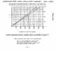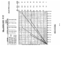
1
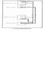
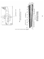
Me-262 A-1 Pilots Handbook
Provided courtesy of
Zeno’s Warbird Video Drive-In
www.zenoswarbirdvideos.com
c 2005 www.zenoswarbirdvideos.com
Section 1 - DESCRIPTION
GENERAL
a.
The Me-262 is a single-place, jet-propelled aircraft used as
a fighter-bomber. The low swept-back wing is a symmetrical
airfoil section with square tips. Automatic leading edge wing
slots are incorporated in the wing design. The fuselage of
of the Me-262 is triangle shaped with an unusually long nose,
and a tail assembly of a single fin and rudder. The undercarriage is a squat tricycle type. Power is provided by two
propulsion units under the wing.
b.
The approximate dimensions of the aircraft are as follows:
(1)
Wing span 41 ft.
(2)
Overall length 34 ft. 9 in.
(3)
Height of fin above the ground 11 ft. 4 in.
c.
The airplane gross weight runs between 10,154 lb. (empty)
and 14,272 lb. (with maximum fuel).
d.
The propulsion units consist of two Junkers TL (Jumo 004) axialflow type jet engines. The power output is controlled by the
rate at which fuel is supplied to the burners.
FLIGHT CONTROLS
a.
The flight controls are conventional, using push-pull rods
throughout.
(1) The ailerons were designed to use servotabs, but the air
craft received have had the aileron tabs converted to a ground
adjustable type, using turnbuckles for adjustment.
(2) The elevator trim tabs were also intended to be of the
servotype, but, on the aircraft received, have been fixed
by riveting in position.
(3) The rudder employs a controllable tab, operative from
the cockpit. The tab control is on the left side of the
cockpit. (See fig. 2-11). A position indicator (See fig. 2-12)
indicates the amount of tab adjustment.
b.
There is a horizontal stabilizer trim control and indicator.
The angle of incidence of the stabilizer is varied by an
electric motor to trim the aircraft. Control is operated by
lever. (See fig. 2-3.) Horizontal stabilizer position is
shown on indicator (See fig. 2-4.) Power is supplied to the
controls by the switch in the main switch panel. (See fig. 4-9.)
c.
Wing flaps.
(1) The Handley-Page type flaps are operated by two push
buttons. (See fig. 3-2). Flap position is indicated by graduations of 0°, 10% 20°, 30°, 40% and 50° marked on the upper
surface of the flap; the 20° position used for take-off is
marked in red.
(2) Emergency lowering of the wing flaps is accomplished by
the use of an emergency compressed air system. Operation is
accomplished by opening the operating handle (See fig. 2-2),
two complete turns. Warning: Be sure the valve is opened
two complete turns.
THROTTLE CONTROLS
a.
The throttle controls are located at the pilot's left, (See
fig. 2-9) and are the only power controls on the airplane.
The black buttons, one on each throttle, are used to close
the circuits for starting ignition on the engines. The
throttles are equipped with stops to prevent accidental full
closing and stalling of the engines.
LANDING GEAR CONTROLS
a.
Under normal conditions the landing gear is raised or lowered
by use of the two push buttons. (See fig. 3-3). It is
hydraulically operated, but because of the low capacity of
the hydraulic pump, it is slow in operation.
b.
Compressed air is used for emergency operation of the under
carriage, but lowers the nose wheel and main undercarriage fair
ing only. The undercarriage itself falls under the influence
of gravity, and locking may require the assistance of slide
slipping.
Operation of the compressed air emergency system is
accomplished by opening the operating handle (See fig. 2-1)
at least two complete turns. Warning: Be sure to open two
complete turns.
c.
Landing gear position indicators are provided for each unit
of the undercarriage indicator, (See fig. 3-5) left main gear
indicator, (See fig. 3-6) nose wheel, and indicator, (See
fig. 3-7) right main gear.
BRAKE CONTROLS
a.
The brakes embody a conventional hydraulic system, independent
of the landing gear and flap hydraulic system. Operation is
accomplished by applying pressure with the toes on the rudder
pedals.
b.
A brake is also incorporated in the nose wheel. Operation is
accomplished by use of the nose wheel brake control lever, (See
fig. 1-17).
www.zenoswarbirdvideos.com
HYDRAULIC SYSTEM CONTROLS
a.
The engine driven hydraulic pump is in operation whenever the
port engine, to which it is attached, is operating. Because
of the low capacity of the pump, operation of the landing gear
is slow, and time allowance must be considered when approaching
for a landing.
b.
Hydraulic power is used to operate the flaps and landing gear.
c.
A compressed air emergency system is incorporated to be used
for lowering flaps and landing gear in event of failure of the
hydraulic system.
ELECTRICAL CONTROLS
a.
The electrical system is in operation whenever the battery
switch, (See fig. 4-13) and the generator switches, (See
fig. 4-11 and 12) are in the "on position.
b.
A circuit breaker is located to the left side of the cockpit,
(See fig. 3-1) and relieves the entire electrical system in
the event of an overload. The circuit breaker can be reset by
pushing the button (See fig. 3-1).
c.
The external power supply plugs into a socket on the right
hand side of the fuselage just above the wing.
d.
The inverter switch is located in the main switch panel.
fig. 4-10).
(See
FUEL SYSTEM CONTROLS
a.
The capacities of the four (4) fuel tanks are as listed:
1.
Front main fuel tank
240 gal.
2.
Rear main fuel tank
204 gal.
3.
Front auxiliary tank
53 gal.
4.
Rear auxiliary tank
158 gal.
655 gal.
Total
b.
Fuel is supplied to the engines from the two main fuel tanks,
one located in front of the pilot and one in back of the pilot.
Either engine can be supplied from either tank, depending upon
the position of the fuel selector and shut off controls located
next to the throttles. (See fig. 2-10). The fuel pumps are
put into operation by the push button switches located in the
main switch panel. (See fig. 4-3 and 4.)
c.
Fuel transfer is accomplished by operation of the push button
switch located in the main switch panel. (See fig. 4-2). Fuel
is transferred from the rear auxiliary tank to the main fuel
tanks only. Transfer from the auxiliary fuel tank located
beneath the pilots' compartment is accomplished by pumping
into the rear auxiliary tank and then into the main fuel tanks,
Fuel transfer is automatic upon operation of the fuel transfer
switch. Fuel is transferred at unequal rates into the forward
fue1 tank.
PILOT HEAT CONTROLS
a.
Pilot heat is applied by operating the pilot heat switch
located in the main switch panel. (See fig. 4-8).
WINDSHIELD DEFROSTING
a.
Windshield defrosting is accomplished by applying windshield
heat through operation of the windshield heater switch. (SEE
fig. 4-23).
NAVIGATION LIGHTS
a.
The lights are operated by a switch located in the main
switch panel. (See fig. 4-7).
www.zenoswarbirdvideos.com
Section 2 - PILOT OPERATING INSTRUCTIONS
BEFORE ENTERING PILOT"S COMPARTMENT
a.
Flight Restrictions: Only normal flying maneuvers should be
performed with this airplane until further data is obtained.
No high-speed dives should be run.
b.
Air-Speed Limitations: The maximum allowable airspeed (IAS)
is 950 km/hr (590 mph.)
c.
Center of Gravity Position: With the three forward fuel tanks
full and the rear one empty, the best center of gravity position will be maintained. This is 156 in. aft of the nose.
d.
Take-off Gross Weight and Balance:
(1) The normal take-off gross weight is 14,272 lb, 10,154 1b.
basic, plus 4118 lb. for fuel, pilot, and ballast.
(2) The most rearward permissible position of the center of
gravity is 30% MAC. If this position is exceeded, the airplane
becomes unstable about the lateral axis, is apt to yaw about
the vertical axis, and automatically stalls in a turn. Under
normal conditions of fuel capacity this position is not exceed
ed. Refer to fuel through directions.
e.
How to Gain Entrance: The cowling on the left hand engine
incorporates two steps and a hand-hold which permit easy access
to the top of the wing. Another step is provided in the
fuselage below the cockpit canopy for entry into the cockpit.
The central portion of the canopy is hinged along the right
hand edge and is raised from the left hand side. It can be
locked in place only from the inside.
ON ENTERING PILOT'S COMPARTMENT
a.
Check before all flights:
(1)
Check weight and balance.
(2)
Check Form 1.
(3)
Diluter lever on "normal oxygen."
(4)
Oxygen regulator altitude dial on "normal."
(5)
Oxygen pressure 400 to 450 lb. one sq. in.
(6)
Set the altimeter and clock.
(7)
Battery switch (See fig. 4-13) "off."
(8)
Generator switches (See fig. 4-11 and 12) "on".
(9)
Pitot heat switch (See fig. 4-8) "off."
(10)
b.
External power source connected.
Special Check for night flying:
(1) Navigation lights (See fig. 4-7).
FUEL SYSTEM MANAGEMENT
a.
Fuel Selector Switches: The fuel valve controls, (See fig.
2-10) have three positions; rear position fuel shut off; center
position rear main fuel tank; and forward position front main
fuel tank. In order to maintain a suitable center of gravity,
the following selector valve positions have been found to be
practical:
(1) When starting the jet units and taxiing:
selector valves at "rear main fuel tank."
Both fuel
(2) During take-off and in flight: Left hand unit at "front
main fuel tank" and right hand unit at "rear main fuel tank."
After about ten min of flying time, switch on the fuel transfer
system off the fuel transfer system when the fuel gage shows
900 liters (235 gal) as there may be danger of fuel running over,
b.
Fuel
side
Fuel
(600
fuel
into
Transfer: Fuel transfer switches are located in the right
of the cockpit, main switch panel. (See fig. 5-1).
is pumped from the 53 gal (200 liter) tank to the 158 gal
liter) tank and then to the front and rear main tanks. The
is pumped into the rear main tank at a faster rate than
the front main tank. The ratio is 3:1.
STARTING PROCEDURES
Warning: All personnel should keep a minimum distance of seven ~
"
(7) feet from the intake and exhaust openings of the
engines.
a.
(1) Connect external battery.
(2)
Turn on:
(a)
Battery switch
(b)
Inverter
(c)
Generators
www.zenoswarbirdvideos.com
Note:
b.
Electric fuel pumps are provided and can be used in cold
weather conditions when unit is hard to start. These pumps
supply gasoline to the burners. They should be shut off
when a speed of 3000 rpm is reached.
(3)
Turn fuel selector valve "off".
(4)
Throttles closed.
(5)
Push down starter handle to prime Riedel starting motor.
(6)
Pull starter handle and hold; at the same time press
tachometer button and hold. This puts tachometer in low
speed range.
(7)
When jet unit has reached 700 to 800 rpm, press ignition
button on right side of throttle and hold. A deep throbbing
noise is heard as the unit begins firing. The speed
will increase to 1800 to 2000 rpm at this time.
(8)
Release starter handle and tachometer button, open fuel
selector valve (rear tank position) and slowly advance
throttle to 3000 rpm.
(9)
At 3000 rpm release throttle ignition button.
The jet unit is now running on the main fuel supply.
temperature must not rise above 650°C.
Exhaust
If the jet unit fails to start, release throttle-ignition
button. The tail pipe should be wiped clean of any injected fuel
before repeating starting process. Otherwise a fire may start.
Whenever there is fire or smoke in the turbines, release starter
handle at once. Due to this fire hazard, a fire extinguisher
should always be ready.
WARM-UP AND GROUND TEST
(1)
Trim stabilizer at 0° tp +1°.
tank use +2° to +3°.
With full auxiliary
(2)
Set left engine fuel selector valve on "front tank and
right engine fuel selector valve on "rear tank".
(3)
Set flaps at 20°.
of flaps.
(4)
Open throttles very slowly to 7000 or 8000 rpm. At this
speed the needle valve in the tail pipe should move to the
fully extended rearward position. This is visible from
the cockpit and indicates that maximum thrust is being
developed.
(5)
Check exhaust temperature gage for not over 650°C.
(6)
Check fuel pump pressure gages for 50 to 80 kg/cm2.
Graduations are marked on upper surface
TAXIING
a.
Caution must be used in taxiing because the rudder is
ineffective and steering by engine thrust is difficult as
thrust builds up too slowly. Brakes are the only means of
control, and taxiing should be done with jet units running at
4000 to 6000 rpm. The tail of the ship must not be turned
toward inflammable objects.
TAKE-OFF
(1) Hold aircraft with main wheel brakes and open throttles
very slowly to 7000 rpm.
(2) Release brakes and open throttles fully. Make direction
al corrections with brakes only. After flying speed (approximately 112 to 125mph (180 to 202 km/hr)) has been attained,
pull gently back on stick to raise nose wheel and make the
take-off.
(3) Apply brakes and retract gear when airborne. Landing
gear signal light should indicate wheels in "up" position.
(4)
Note:
Retract flaps - airplane will not drop through.
By opening throttles too fast up to 7000 rpm there is danger
of causing cavitation in one of the compressor stages, that is,
by running up too quickly the compressor is overloaded and the
smooth air flow breaks up just as it does on a stalled wing. If
take-off is continued, insufficient air flows through but the
same amount of fuel is injected, resulting in insufficient
power.
ENGINE FAILURE DURING TAKE-OFF
a.
If the speed of the aircraft is low, close the throttles and
apply the brakes. (Main wheel brakes are foot-operated, nose
wheel brake is hand-operated).
b.
If already airborne, retract the landing gear as soon as
possible, keep the nose down, and use the rudder as necessary
to maintain direction until the rudder trim can be adjusted.
Continue around the pattern, turning in the direction of the
good engine. Minimum single engine speed is 260 km/hr (160
mph).
CLIMB
a.
The best climbing speeds are given in the take-off and climb
chart in Appendix 1.
www.zenoswarbirdvideos.com
GENERAL FLYING CHARACTERISTICS
a.
Stability:
(1) This airplane has good aileron control at all altitudes
and will do a good slow roll.
(2) The airplane holds its speed in tight turns much longer
than conventional types.
(3) In climbing or turning, automatic slots in the leading
edge of the wing open when the speed drops to 450 km/hr
(280 mph). Slots open at 300 km/hr (185 mph) when the airplane
is in a gliding angle.
b.
Trim Changes:
The stabilizer trim control should not be used when going
into or pulling out of a dive. The reason for this is that the
entire stabilizer is moved up and down by an electric motor
drive actuated by the trim control lever. Thus a slight
deflection has a large effect, and it is easy to over-control,
causing the ship to nose over or pull up more abruptly than
intended.
c.
Changing Power in Flight:
Move the throttles slowly forward or aft.
STALLS
a.
Stalling characteristics are good, there being no bad tendencies
to fall off into a spin.
SPINS
a.
No spins are to be attempted with this airplane.
PERMISSIBLE ACROBATICS
a.
No acrobatics are to be performed.
DIVING
a. There is reported to be no flutter while diving, possibly due
to the high position of the horizontal stabilizer in relation
to the wing.
b.
Speeds of 950 km/hr (590 mph) are reported to have been attained
in a shallow dive 20° to 30° from the horizontal. No vertical
dives were made. At speeds of 950 to 1000 km/hr (590 to 620 mph)
the air flow around the aircraft reaches the speed of shound, and
it is reported that the control surfaces no longer effect the
direction of flight. The results vary with different airplanes;
some wing over and dive while others dive gradually. It is also
reported that once the speed of sound is exceeded, this condition
disappears and normal control is restored.
SPEED AND RANGE
Flight Condition
True Air Speed (Indicated)
Max speed, 20° to 30° dive
950 km/hr (590 mph)
Take-off with full fuel load
(no bombs)
Cruising speed
180 to 202 km/hr (112 to 127mph)
Max speed, level flight
830 km/hr (515 mph)
Landing approach
250 km/hr (155 mph)
Stalling speed with full fuel load,
landing gear and flaps down
202 km/hr (125 mph)
750 km/hr (465 mph)
The flight duration of the aircraft varies from 45 to 90
min. Time of flight at low altitudes (below 10,000 to 12,000
ft.) is 45 to 50 min. At altitudes above 12,000 ft the time of
flight is 60 to 90 min. The increased efficiency with altitude
is a result of decreased air pressure.
TO TURN OFF JET UNIT DURING FLIGHT
a.
Training or test flights:
(1)
Close throttle to idling position.
(2)
Turn off fuel pump, allowing rpm to decrease.
(3)
Fuel selector valve off.
(4)
Throttle closed.
(5)
Press ignition button throttle for five seconds.
TO START DURING FLIGHT
a.
Do not start above 4 km (13,100 ft) because of fire hazard.
www.zenoswarbirdvideos.com
(1)
Reduce airspeed to 300 km/hr (186mph).
(2)
Throttle closed.
(3)
Turn on fuel pump.
(4)
Press ignition button throttle until rpm increases by 1000.
(5)
Open fuel selector valve.
(6)
Advance throttle slowly to idling position.
(7)
Release ignition button when rpm is constant.
(8)
Adjust rpm to that of other unit.
APPROACH AND LANDING
a.
Normal Landing:
Do not lower landing gear above 4000 km/hr (248 mph). It may
be expected that the nose will rise sharply as the landing gear
starts down, but once the wheels are in landing position the
aircraft will assume a normal attitude by retrimming stabilizer.
The landing approach is made at 250 km/hr(155 mph). Use flaps
as needed and carry 6000 to 7000 rpm so that throttles can be
opened quickly in case of a go-around.
Note:
b.
If rpm is less than 6000, any advance in throttles must be made
slowly to 7000 rpm before opening wide. The airplane stalls at
180 to 202 km/hr (112 to 125 mph). In case of a very short flight
in which the fuel has not all been used from the the auxiliary
tanks, use caution in landing as the allowable landing weight is
exceeded due to the fuel load.
Take-off if landing is not completed:
(1) If 6000 to 7000 rpm or over has been maintained on the
approach, open throttles fully in going around.
Note:
If rpm has fallen below 6000 it is necessary to bring the units up
to 6000 to 7000 rpm slowly, just as in take-off, before opening
throttles.
(2)
Brake and retract landing gear.
(3)
Gradually raise flaps to take-off setting of 20°.
STOPPING UNITS
(1)
Close throttles completely and press ignition buttons.
(2)
Shut off fuel selector valves.
(3)
Open fuel dump valve switches.
In the event that power units should begin to burn,
pull starter handles, re-ignite power plant and then
repeat above shutting down process.
BEFORE LEAVING THE PILOT'S COMPARTMENT
a.
Turn all switches off.
www.zenoswarbirdvideos.com
Section 3 - FLIGHT OPERATING DATA
ENGINE OPERATING DATA
Airplane Model Me-262 A-l
Condition
Exhaust Gas Temperature
Fuel Pump Pressure
Maximum
650°C.
80 kg/cm2
Maximum
----
50 kg/cm2
Minimum Fuel Grade Jet
engines: AN-F-32
Riedel starters:
AN-F-23 (with % pt of engine oil added to each
gallon).
Oil Grade
AAF Spec. No. 3606
Operating condition
RPM
Time Limit
Take-off
8700 ± 200
5 min
Military
Max continuous (90%)
“
“
10 min
8400
AIR SPEED CORRECTION DATA
(Information not available pending flight tests.)
Section 4 - EMERGENCY OPERATING INSTRUCTIONS
FLIGHT ON ONE JET UNIT
a.
The aircraft will fly at 450 to 500 km/hr (280 to 310 mph) on
one jet unit. It operates best over 3 km (10,000 ft).
b.
The minimum single engine speed of 260 km/hr can only be
reached by climbing too steeply or with landing gear down.
c.
Bank only in the direction of the good jet unit unless speeds
over 260 km/hr (160 mph) are maintained.
EMERGENCY SHUTDOWN OF JET UNIT DURING FLIGHT
a.
Jerk throttle closed.
b.
Turn fuel pump off.
c.
Turn fuel selector valve off.
EMERGENCY OPERATION OF LANDING GEAR AND FLAPS
a. Compressed air is used for emergency operation. It lowers the
nose wheel and main landing gear fairing. The main gear falls and
locks by the influence of gravity. If it does not immediately lock
it can be helped by side-slipping. Both the landing gear and the
flaps lower more quickly by the use of compressed air than
hydraulically. The main gear goes down in 2 to 3 sec and the nose
wheel goes down in 5 to 10 sec. Note: Two to three turns of the air
valve are necessary to put compressed air into operation.
TIRE BLOWOUT DURING TAKE-OFF OR LANDING
a. Keep the airplane straight by using corresponding throttles
and applying opposite brakes until the airplane comes to a
stop.
Bail-OUT
a.
Pull the emergency handle for cockpit canopy release. Bailout
to one side. Wait approximately two seconds before pulling
the ripcord.
www.zenoswarbirdvideos.com
LANDING WITH ONE JET UNIT
a.
Approach the field, turning in the direction of the good
jet unit.
b.
Lower the landing gear by compressed air (two complete turns
of air valve) when 3 to 4 km (2 to 2.5 miles) out on the land
ing approach. Main gear goes down in 2 to 3 sec and the nose
wheel goes down in 5 to 10 sec.
c.
Lower flaps as needed, as the airplane will not go around
again on one jet unit.
d.
When the landing gear has been lowered by compressed air,
the landing gear down button must be pressed when the jet
units are running, before the next take-off.
POSSIBLE FAILURES OF THE ENGINES IN STARTING AND IN FLIGHT
a.
In Starting
(1)
The Riedel Motor Does Not Start:
The electro-motor in the Riedel is turning the jet unit
over slowly. The voltage should read 20 v, in which case do
not use the starter switch for more than 10 sec to avoid
burning out the electro-motor.
(2) The Riedel motor sounds as if it were running, but no
rpm is indicated with the tachometer in the low-speed range.
(a)
Tachometer inoperative.
(b)
Starter claw is broken.
(3) The ignition does not respond immediately; press the
ignition button several times. If ignition finally takes place,
long flames will come out of the jet unit. This will also
happen if fuel has previously run into the jet unit. These
flames will blow out.
(4) The ignition is accidentally turned on when the jet unit
is stopped, and flames come out of the unit. The ignition
should be released and the Riedel motor started so that the
air flow will extinguish the flames. If the Riedel motor is
not used, a mechanic can either blow compressed air through
the front or use a fire-extinguisher at the rear.
b.
In Flight.
(1) Jet unit is extinguished:
Indicated by:
(a) Drop in rpm.
Causes:
(2)
(b)
Drop in fuel pressure.
(c)
Drop in gas pressure.
(d)
Drop in tail-pipe gas temperature
and trailing of white smoke.
(a)
Throttle pulled back further than
idling position.
(b)
Stoppage of fuel supply.
(c)
Insufficient injection pressure at
high altitudes.
Broken vanes in jet unit:
Indicated by:
Vibration of the unit.
Action:
Turn off the jet to prevent the fuel
lines from breaking and causing a fire.
(3)
Damaged turbine starter vanes:
Indicated by:
(a)
Fuel pressure increases rapidly.
(b)
Gas pressure increases rapidly.
(c)
Gas temperature increases rapidly.
Action:
Turn off the jet unit immediately
to avoid fire.
(4)
Injection nozzle clogged:
Indicated by:
(a)
Fuel pressure increases rapidly.
(b)
Gas temperature is abnormally high
or low.
Action:
Turn off the jet unit immediately
to avoid fire.
(5)
Loss of oil or oil pump inoperative:
Indicated by:
(a)
RPM surges upward.
(b) Gas temperature rises to the limit
of gage.
Action:
Turn off the jet unit immediately
to avoid fire.
www.zenoswarbirdvideos.com
(6)
Thrust governor inoperative or the nozzle pin adjustment
broken, in either case the thrust nozzle pin advances
to the final notch:
Indicated by:
Action:
(7)
(a)
Fuel pressure increases rapidly.
(b)
Gas pressure increases rapidly.
(c)
Gas temperature increases rapidly.
Turn off the jet unit immediately
avoid fire.
Landing gear retraction trouble:
(a) If the landing gear does not come up when the button
is again pressed, reduce the speed to 160 mph and suddenly
push down the nose.
(b) If the signal lamp does not work, the retraction of
the landing gear can be checked as follows:
(1) If a slight rush of air is heard and the
speed is 405 to 435 mph, the nose wheel is still
down.
(2) If a strong rush of air is heard and the speed
is 280 to 310 mph, the entire landing gear is still
down.
www.zenoswarbirdvideos.com
www.zenoswarbirdvideos.com
Section 5 - OPERATIONAL EQUIPMENT
HEATING AND VENTILATING
a.
Heating of the cockpit is obtained by operation of the
control marked "Cabin Heat". (See fig. 1-11).
b.
Ventilating is accomplished by opening a small air
scoop on the upper left of the fuselage just forward
of the canopy. The scoop is operated by means of a control lever. (See fig. 1-18.)
OXYGEN SYSTEM
a.
This is a standard low pressure oxygen system with a
diluter demand oxygen pressure breathing regulator,
Type A-14.
b.
Normal oxygen pressure (fig. 2-13) is 400 to 450 lb/sq in.
ARMAMENT
A.
Not applicable.
COMMUNICATIONS EQUIPMENT
a.
The airplane has a standard installation of an SCR-522
transmitter and receiver with a BC-602A control box.
APPENDIX ONE
LENGTH OF RUNWAY WITH $&% GAL FUEL (NO BOMBLOAD).
Concrete
Grass Strip
Take-off
3750-4350 ft
4350-5250 ft
Landing
3750-4350 ft
3150-3750 ft
with 528 gal of fuel
Concrete
Grass Strip
Take-off
4350-4950 ft
4950-5850 ft
Landing
4350-4950 ft
3750-4350 ft
FLIGHT
Altitudes
0 to 4 km (0 to13,000ft)
4 to 6 km
(13,000 to
19,700 ft)
6 to 8 km
(19,700 to
26,200 ft)
8 to 10 km (26,200 to
32,800 ft)
NOTE:
True Climbing Speeds
(Indicated)
climb at 450 km/hr (279 mph)
climb at
500 km/hr (310 mph)
climb at 550 km/hr (342 mph)
climb at
600-650 km/hr
(372 to 403 mph)
The German airspeed indicator registers true airspeed,
above 400 km/hr, due to altitude compensation in the
instrument.
www.zenoswarbirdvideos.com
ITEMS OF TYPICAL LOADING
Oil ---------------------- 4.5 gallons at station 100.13
Pilot and Chute ----------- 200 lb. at station 163.39
Fuel---------------------- See fuel graph
Ammunition --------------- See Ammunition and Ballast Graph
Ballast ------------------ See Ammunition and Ballast Graph
Jettisonable Tanks ------- (Two) 66 lb. at station 93.31
Jettisonable Tank
Hanging Fittings --------- 22 lb. at station 93.31
To derive center of gravity in percent of mean aerodynamic
chord:
arm - 138-43 x 100 = %MAC
76.06
NOTE:
Most forward allowable center of gravity is 18.5% MAC.
Most rearward allowable center of gravity is 30% MAC.
www.zenoswarbirdvideos.com
www.zenoswarbirdvideos.com