1
SUPER BLINKY
SMT PRACTICE KIT
Ramsey Electronics Model No.
SBRGB
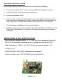
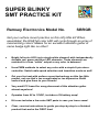
Get your surface mount practice on this nifty little kit! When
assembled, the RGB full color LED will cycle through an array of
mesmerizing colors! Makes for an excellent attention getter or
name badge light like no other!
•
Bright full-color LED (not a single white element) with independently
drivable red, green and blue LED elements. These elements are
matched for a true “white” output or any color in between!
•
Uses PWM methods to select any color with a simple 8-pin microcontroller. Switch-able speed selection and transition mode as well!
•
Get your feet wet with surface mount technology on this fun little
project, not one that’s too complicated or too expensive. Build
several and give them to your friends!
•
Very small PC board for easy placement of this attention getter
almost anywhere!
•
Operates from 6V to 12VDC, includes a 9V battery snap!
•
Kit even includes a few extra SMT parts in case you loose some!
•
Clear, concise instructions to guide you step-by-step to a finished
product that works the FIRST time!
SBRGB • 1
PARTIAL LIST OF AVAILABLE KITS
RAMSEY TRANSMITTER KITS
• FM100 Professional FM Stereo Transmitter
• FM25B Synthesized Stereo Transmitter
• AM1, AM25 AM Transmitters
• TV6 Television Transmitter
RAMSEY RECEIVER KITS
• FR1 FM Broadcast Receiver
• AR1 Aircraft Band Receiver
• SR2 Shortwave Receiver
• AA7 Active Antenna
• SC1 Shortwave Converter
RAMSEY HOBBY KITS
• SG7 Personal Speed Radar
• SS70A Speech Scrambler
• SP1 Speakerphone
• WCT20 Wizard Cable Tracer
• ECG1 Heart Monitor
• LABC1 Lead Acid Battery Charger
• IG7 Ion Generator
• CT255 Compu Temp Digital Binary Thermometer
• LC1 Inductance-Capacitance Meter
RAMSEY AMATEUR RADIO KITS
• HR Series HF All Mode Receivers
• QRP Series HF CW Transmitters
• CW7 CW Keyer
• CPO3 Code Practice Oscillator
• QRP Power Amplifiers
RAMSEY MINI-KITS
Many other kits are available for hobby, school, Scouts and just plain FUN. New
kits are always under development. Write or call for our free Ramsey catalog.
SUPER BLINKY PRACTICE KIT INSTRUCTION MANUAL
Ramsey Electronics publication No. SBRGB Rev 1.2
First printing: December 2001
COPYRIGHT 2001 by Ramsey Electronics, Inc. 590 Fishers Station Drive, Victor, New York
14564. All rights reserved. No portion of this publication may be copied or duplicated without the
written permission of Ramsey Electronics, Inc. Printed in the United States of America.
SBRGB • 2
Ramsey Publication No. MSBRGB
Price $5.00
KIT ASSEMBLY
AND INSTRUCTION MANUAL FOR
SUPER BLINKY SURFACE
MOUNT PRACTICE KIT
TABLE OF CONTENTS
Introduction ...................................... 4
Circuit Description ............................ 5
Parts List .......................................... 9
Assembly Steps ............................... 10
Using the SBRGB ............................ 16
Project Idea ...................................... 16
Schematic Diagram.......................... 17
Parts Layout Diagram ...................... 17
Troubleshooting Guide..................... 18
Specifications ................................... 18
Warranty .......................................... 19
RAMSEY ELECTRONICS, INC.
590 Fishers Station
Victor, New York 14564
Phone (585) 924-4560
Fax (585) 924-4555
www.ramseykits.com
SBRGB • 3
INTRODUCTION
The Super Blinky was thought up as a way to show off the latest technology in
RGB (Red, Green, Blue) color LEDs. These babies have always been tempting
to play with in order to see just how many colors they could reproduce. The
problem was that the darned RGB LEDs were so expensive (the Boss just
about had a heart attack). Some of these LEDs cost more than $19.00 a piece
as of the writing of this manual. They use the latest technology to achieve an
incredibly bright output and are well worth the cost in some applications. From
a kit point of view however, they are way too expensive! When the datasheet
became available for the LED we’re using and the pricing turned out to be
much more reasonable then those we had looked at before, I knew the time
had come!
So how did I get around the Boss you may ask? I turned this into a surface
mount practice kit that met the requirements so many of you were asking for via
the web. It contains a few simple and some challenging parts to work with (but
not so complicated that you are left with a headache and a strong desire to give
up and go watch TV). Not to mention after your done, you get a nice reward
when it works right off the bat!
Personally I could stare at this color changing LED for a long time. In fact, the
Boss thinks that’s all I have been doing lately! Some of the colors the SBRGB
produces are quite amazing. The red portion is a very deep color, to the point
that it almost irritates the eye. When combined with the deep blue, it makes for
a fantastic violet. Now add in the high intensity green into the mix and you have
some pretty cool colors. Ok, now how do I get these colors to change?
On to the next section…
SBRGB • 4
CIRCUIT DESCRIPTION
In the old days, we used to make things as simple as possible. The original
blinky used two transistors, two capacitors and four resistors. This simple circuit
is now seen everywhere in blinky kits so we decided to use a new and novel
approach with this one. Our new blinky kit requires over 20,000 transistors,
three capacitors, five resistors, and a few other parts. The difference is we can
make the LED do anything we want, well almost anything.
The part which does most of the work is an 8-pin PIC micro-controller chip.
Frankly these little things are amazing. They are perfectly suited to perform
small tasks like this one. They are fast, easy to program, and require almost no
external components to make them function. The PIC controller is programmed
to pulse width modulate each of the 3 colors in various duty cycles to achieve
the variety of colors we are looking for. What to we mean by pulse width modulate?
Pulse width modulation means that we are changing the percentage of on time
vs. off time in a known amount to achieve a specific brightness. In our case we
are pulsing width modulating with a resolution of 256 steps for each color. This
means we have a resolution of 256*256*256 = 16,777,216 colors! We may not
actually achieve this number due to limitations on switching speed, but we’ll still
get more than your eye can discern.
Now, let’s say we want the red LED at 50% of full brightness. The red element
needs to turn on and off in equal amounts fast enough that our eye cannot see
it blink. How is this done in code? If you are familiar with PIC, here is a snippet:
toploop:
clrf
movlw
movf
bsf
pwmloop:
decfsz
goto
bcf
pace
0x7F
red
GPIO,RED
;Make the RED led turn on at 50% brightness.
;For the full 256 counts
;50%, leave red on for this many counts of 256
;Into the red register
;Turn on the Red LED
red,F
reds
GPIO,RED
;Decrement the red register
;If red not at zero, leave the Red LED on
;If red at zero, turn the Red LED off
reds:
pace,F
pwmloop
toploop
;Decrement the pace
;If not at zero, keep looping until 256 counts done.
;Continue on, or loop to toploop
decfsz
goto
goto
Ok, so you may not have done much assembly programming before. This is a
real neat example to help you learn what assembly code can do. The best way
to read this code is to look at the text after the semicolons (here is where the
descriptive information resides). The text on the far left are labels that identify
points in the program flow where you may whish the program to start from or
jump to (remember Basic’s goto 10? 10 was a label for a line).
SBRGB • 5
All that this example code does is to set the Red LED at 50% brightness. If we
wanted to change it to 25% brightness, we would change line 2 to:
movlw 0x40
;25% (256/4 = 64 base10 = 40 HEX)
Now imagine that we vary the percentage value in real time using a variable
rather than a constant of 0x40 (HEX numbering system). On top of this, use a
Sine lookup table to produce smooth changes. When we apply these principles
to all three color elements in the LED at random, you get the Super Blinky!
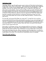
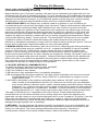
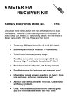
So how would you achieve an orange color with the SBRGB? First you would
figure out what percentage of each color needs to be on to produce orange.
From the choices of Red, Green and Blue, Orange resides somewhere between Green and Red. Mostly towards Red end. This means Red will be at a
full 100% duty cycle (255), Green will be around 50% (127), and Blue will be off
at 0% (0).
RED
On
Off
0
Time--->
255
GREEN
Time--->
255
Time--->
255
BLUE
Time--->
255
Time--->
255
Time--->
255
On
Off
0
On
Off
0
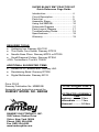
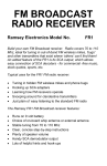
How about a nice violet color?
RED
On
Off
0
Time--->
255
GREEN
Time--->
255
Time--->
255
BLUE
Time--->
255
Time--->
255
Time--->
255
On
Off
0
On
Off
0
SBRGB • 6
As shown, violet is created mostly by blue with some red. If you own a computer, you can try these shades out by changing your display properties and
custom selecting a color. It will allow you to enter color values in Red, Green,
and Blue in a range of 0-255 just like the Super Blinky!
The timing charts only show a small percentage of the overall PWM waveform. To keep the LEDs from appearing to blink, we have to keep them flashing at a rate faster than our eye can see (at least 30 times a second). Right
now we are flashing at a rate of 280 times a second so it’s more than fast
enough.
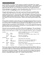
If we want to fade from white to blue, the trick is to fade at a reasonable rate of
speed according to our 280 times a second flash rate. To fade from white to
blue in one second, we need to start with 255 and then subtract one from both
red and green value once per cycle (skip a few cycles in between to stretch
the time a bit). At the end of 280 cycles, the red and green element drive rate
is at zero and blue is left completely on.
On
Off
0
Time--->
0255
Time--->
0255
Time--->
0255
Time--->
0255
Time--->
0255
Time--->
255
Time--->
0255
Time--->
0255
Time--->
0255
Time--->
0255
Time--->
0255
Time--->
255
Time--->
0255
Time--->
0255
Time--->
0255
Time--->
0255
Time--->
0255
Time--->
255
On
Off
0
On
Off
0
The Super Blinky actually gets a bit more complicated than this in order to
achieve the eye pleasing color changes in uneven sinusoidal steps (versus
the examples linear ones). This is accomplished with lookup data tables.
The rest of the circuit consists of the power supply and the LED itself. The
power supply is a simple 5V regulator that is required to keep the supply voltage to the micro-controller at +5V (it cannot handle more than that). Unfortunately the Super Blinky will not operate at +3V with a lithium button cell
(though two cells will do) since the blue element of the LED requires at least
4.0V before it will even turn on. The circuit will run, but no blue LED!
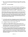
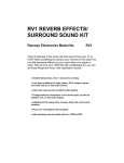
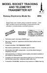
Take a look at the following specification sheet on the provided LED. Notice
the forward voltages required to turn on the individual elements in the Vf = V
typ column and the relative intensity when looking straight into the LED in Iv =
mcd typ column (mcd is intensity in mili-candelas). Mili-candelas are deceiving
in that they only tell you how bright an LED is from a certain perspective. We
are using a diffused lens so the number is much lower than with a water-clear
lens that would focus all the light in a narrower beam. Same LED, different
lens, higher numbers! Lens selection all depends on your application. The diffused style is used here to ensure a maximum viewing radius.
SBRGB • 7
Another interesting point to note is that for this LED to have enough green
content to match up with the blue and the red components, two elements were
needed! To achieve a good quality white color, we have to provide the proper
current from the driver for each color element. Here is the key to the values
chosen for resistors R1, R2, and R3. We want 20 mA, 40 mA, and 20 mA in
each of the Red, Green, and Blue elements respectively to get a good white
when fully on. After experimenting a bit, we decided to change the scaling to
5 mA, 60 mA, and 10 mA to obtain a nice vivid green and a brighter white
without changing the overall brightness. The low duty cycle (‘on’ time) still
yields a low average current so the slightly higher drive will not harm the green
elements.
LED
COLOR
Lens
Type /
Color
UL RED
HE
GREEN
UL
BLUE
Electrical-Optical Characteristics
(Ta=25C)
Full Viewing Angle
If =
Iv =
Vf = V
Ip nm
mA typ mcd typ
typ
20
20
1.7
660
20
40
DIFFUSED
40
30
2.0
565
20
6
4.0
430
SBRGB • 8
60
0
20
40
60
PARTS SUPPLIED WITH THE SUPER BLINKY KIT: Note a few extra chip
parts included.
Capacitors
2 0.1 µF chip capacitor (no marking, usually brown) [C1]
2 1 µF electrolytic surface mount capacitors (Silver, marked 1 µF)
[C2,C3].
Resistors
4 10K ohm resistors (Marked 103 on black side) [R5,6]
2 680 ohm resistors (Marked 681 on black side) [R1]
2 51 ohm resistors (Marked 510 on black side) [R2]
2 100 ohm resistors (Marked 101 on black side) [R3]
Semiconductors
1 78L05 Voltage regulator in an SO-8 package. [VR1]
1 PIC12C509SN Micro-controller in an SO-8 package. [U1]
1 RGB Full Color LED (DS-1024-105A) [D1]
1 1N4148 Type switching Diodes (3-pin SOT-23 packages) [D3]
Hardware, Misc.
1 9V Battery Clip
2 2 Pin header for mode selection [J1,2]
2 Jumper Block for 2 Pin header
1” #24 AWG Buss wire [optional power configuration jumper]
1 SB-RGB PC board
Required, not supplied
9V Battery
Required Tools
Small-tipped soldering iron, usually called a pencil iron. Call Ramsey for
more details or to order a soldering iron capable of surface mount if you do
not have one.
Eye Loupe
Pair of tweezers
Length of very thin solder
Patience, it counts as a tool.
A stand or kit vise to solidly hold the board while assembling.
SBRGB • 9
SBRGB ASSEMBLY
Use the boxes to check off your progress as you go along.
Check all received parts against the Parts list. The parts list describes the
various markings that may be found on the kit parts.
In the case of a surface mount component, INSTALL means these steps:
•
Dab a small amount of solder on one pad of the PC board for the
component you wish to install. Usually choose pin 1.
•
Locate the appropriate part from those packed in the kit.
•
Use tweezers to pick up the part by grabbing it across the body, not the
solder connections.
•
Place the part in the assembly location as noted by the silk-screen on the
top layer of the board (the bottom side has no writing on it). Use one hand
to hold the tweezers and part in place.
SBRGB • 10
•
Use the other hand to re-heat the solder dab to melt it to the component
connection.
•
Let the solder cool and then let go with the tweezers. Inspect orientation
and make sure the part is square over the correct pads. Make sure stray
solder connections don’t overlap or short across the adjacent pads.
•
Apply solder to the rest of the pads.
•
Apply a touch more solder to the initial pad to make sure there is a good
solder joint. The rosin core flux will clean the joint and insure stability.
•
If you have too much solder and wish to remove it, use a solder sucker or
solder wick to “soak up” the extra solder. Solder bridges on SMT IC pins
are a frequent occurrence so you should always have some solder wick
handy.
In the case of through hole components:
•
Insert the part (oriented correctly) into its holes or pads on the PC board.
•
If helpful, gently BEND the parts wire leads or tabs to hold it in to make
soldering easier.
•
SOLDER ALL wires or pins of the part. Whether it’s two wires or pads of a
resistor or all pins or pads of an IC socket.
SBRGB • 11
•
Nip or "trim" all excess wires extending beyond each solder connection.
Take care that wire trimmings do not become lodged in PC board solder
connections.
Enough said. . . Let's get building!
You are going to want to use a VERY clean desk space to assemble your
surface mount kit. Drop a resistor into even the smallest amount of clutter and
it will disappear like magic. You would swear a magician was hovering over
your shoulder some times when a part disappears. There are probably
enough parts hidden in the papers on my desk to build an entire
communications system, but we won’t go there… the Boss might read this!
While building, select only one surface mount part at a time. Don’t pour them
out all over the desk! Retrieve a single component (I wet my finger a bit to
have a part stick to it) and place the part in the open work area of your desk.
This makes it easier to pick it up with the tweezers and orient the part so the
markings are on the top for easier trouble shooting if needed. It also provides
me with Tidily Winks practice; *Ping* and I hear the part bounce off of the
other wall and down into the heat register. Hence the extra parts! If you are
really careful, this won’t happen to you.
1. We will begin with a few resistors first. Locate and install R6, the 10K
ohm resistor (marked 103); see SBRGB Assembly for surface mount tips
and don’t worry, we’ve included extra resistors in case one should fly off.
2. Install R5, the other 10K ohm resistor (marked 103).
3. Install R3, a 100 ohm resistor (marked 101).
4. Install D3, the 1N4148 diode in a three pin black package. This
package style is called an SOT-23 which actually covers more than just
one pin layout style. You can have an SOT-23 with 3 pins or 5 so it can
get confusing at times. This diode is used to protect your circuit in case
the battery power is accidentally installed backwards.
5. Locate U1, the pre-programmed micro-controller. Note the dimple on
the top side of the part labeled PIC12C509SN, this indicates pin 1 of the
IC. Look at the silkscreen on the circuit board and find the notch to help
you position the IC correctly. Pre-tin the circuit board by dabbing some
solder on the pad where pin 1 will be placed. Position the part with your
tweezers and solder pin 1 of the IC to the pad. Position the part so that all
eight leads line up properly and stay centered over all eight pads to avoid
shorting pins together.
SBRGB • 12
Time to make a few decisions. Your SBRGB
can be configured in a few different ways
depending on how you want to use it. Things
such as the operating voltage (6 VDC or any
range from 7 to 12 VDC) and the optional
positioning of D1, J1, and J2 (top or bottom
side of the board) will determine which steps
you will now follow. Here are your choices:
Notch
Pin8
Pin1
Notch
Pin8
Pin1
POWER SUPPLY (A for 6VDC, B for 7 to 12VDC operation)
6A. 6 Volt power source (such as two 3 Volt lithium cells). Do not install
VR1. Use the provided piece of buss wire as a jumper to connect from the
output of D3 (pin 1 input of VR1) to the input of U1 (pin 8 output of VR1).
This bypasses the voltage regulator on the bottom side of the board (no
silkscreen) and allows lower voltage operation. Clip off any excess wire
after it is soldered in place. Note the dashed line on the top silkscreen side
indicates this optional configuration when VR1 is not used.
OR
6B. 9 Volt power source (7 to 12 VDC), install the 78L05 voltage regulator
(VR1). Again, pay close attention to the small dimple in one corner of the
IC used to indicate pin 1. There are a few different conventions used in the
industry to note the pin-out of ICs but there should be a notch or a obvious
mark to make things easy to work with. If there is no notch then refer to
the diagram below for the position of pin 1. Pins are always counted from
the lower left of the IC when you can read the writing on it. Align pin one
as before with U1 and mount it in the same fashion.
Pin 16
? writing facing you
Pin 1 Count Counterclockwise
SBRGB • 13
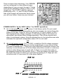
OPTIONAL LED POSITIONING (A for Bottom side, B for Top side)
7A. D1 (colored LED) on the Bottom side. Install D1 (the full-color RGB
LED) from the bottom side and solder it in place. Orientation of this
component is critical because it is made up of polarized diode elements.
Note that the LED has a flat side to help you with its orientation. This flat
side should be mounted in the same direction as indicated on the
silkscreen layout and the parts layout diagram (flat side toward R1).
8A. Install R1, a 680 ohm resistor (Marked 681).
9A. Install R2, a 51 ohm resistor (Marked 510).
OR
7B. D1 (colored LED) on the Top side. Install D1 (the full-color RGB LED)
from the top side and solder it in place (make sure to leave the leads long
enough so that you can top solder it). Orientation of this component is
critical because it is made up of polarized diode elements. Note that the
LED has a flat side to help you with its orientation. This flat side should be
mounted in the same direction as indicated on the silkscreen layout and
the parts layout diagram by the dashed line (flat side toward J1 & J2).
8B. Install R1, a 51 ohm resistor (Marked 510).
9B. Install R2, a 680 ohm resistor (Marked 681).
OPTIONAL JUMPER PLACEMENT
10. The mounting of J1 and J2 is another choice left to you. They are used
to select the speed settings of the color change and blink versus fade
mode operations. When you momentarily close the contacts together, they
tell the micro-controller what to do. The unit is programmed by default for
a fairly fast color changing speed (in fade mode) so you may opt to save
space and not even install them! If you choose to install them on the back
side of the board you can easily solder the leads. Mounting them on the
silkscreened top side requires lifting them off the board a bit so you can
top solder them. Install J1 and J2 if desired.
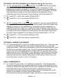
FINAL COMPONENTS
11. Install C2, one of the 1 uF electrolytic capacitors. These capacitors
(like most electrolytics) are polarity sensitive so pay close attention to the
markings. Notice how the positive side of the capacitor’s plastic base has
small beveled corners? These bevels help to indicate the proper
orientation of the part. Match these edges with the markings on the silk
screen of the board to ensure correct positioning.
As discussed in the pre-assembly steps, tinning one of the circuit board
SBRGB • 14
pads before the part installation makes mounting it a lot easier. Set the
lead of the part on the tinned pad, reheat it, now let the capacitor drop
down into the melted solder. Finish up by soldering the other lead and
making sure both solder joints look good.
12. Install C3, the other 1 uF electrolytic capacitor (again watch the
polarity). These capacitors help to smooth out the power supply voltage so
that any glitches will not confuse the micro-controller and cause problems.
13. Install C1, a 0.1 uF ceramic surface mount capacitor. Unfortunately
this capacitor is unmarked, like most small ones of this type. It’s a good
idea to keep all SMT components in their original containers in order to
make identification easier later down the line.
14. Now for your power connection. Install the 9V battery clip. Solder the
Red lead in the hole with the + marking and the Black lead into the other
hole (the one with a lot of copper around it close to the B1 label). If you
plan on using an alternate power source, make sure you use the proper
polarity as described above.
FINISHED!!
Ok, I bet you are excited to go and plug the battery right in but please don’t do
it yet! We need to inspect our work to make sure we did everything correctly.
We don’t want to destroy any of our parts after all!
Check the two electrolytic capacitors for correct orientation. Make sure the
beveled plastic bases are in the same orientation as shown in the parts layout
and the silkscreen.
Check the two ICs to make sure they are in the correct orientation. Pin 1 had
better line up with the pin one marking on the silk screen! If they are installed
incorrectly, we’ll need to fix them. There is a risky but effective way to desolder small SMT ICs like these:
•
Use quite a bit of solder to cover all 4 leads on one side of the part
(effectively shorting them all together). While the solder is still molten on
all four leads, use a pick or your tweezers to gently bend this side away
from the PC board a bit. Don’t use too much pressure or you’ll peel the
traces of the other side right off the circuit board!!!
•
Re-heat and use a solder sucker or wick to clean off the excess solder. Be
very careful with these delicate traces if you use a solder sucker. If you
use braid or wick simply hold it in place to remove the solder; sliding the
wick around on top of the pads tends to remove them from the board!
SBRGB • 15
•
Do the same for the other side, only pick the part off the board this time
with the tweezers when the solder is molten.
•
Use the solder sucker or wick again to clean off the board and any excess
solder left on the components pins.
•
Reposition and re-solder your part to the board.
USING THE SBRGB
There isn’t much to be done after you have inspected the board. Simply clip
on the battery and enjoy the show! You should be able to see the full-color
LED cycle through all the colors of the rainbow in succession. If you don’t, one
of the elements may not be properly soldered or the LED was installed with
the wrong orientation.
To use your SBRGB, short across the pins of J1 (faster) or J2 (slower) to
change the speed of the color cycle. When the speed changes, the LED will
flash indicating a speed change command was received.
The mode selection, Fade or Blink, is chosen by simultaneously shorting both
J1 and J2. The LED will turn a solid color Red or Green (depending on which
side of the board you mounted it on) to indicate that the command has been
received and the mode of operation will toggle from one mode to the other.
Play around with the jumper settings and have fun. You will quickly become
entranced by the swirling effect of the color changes!
PROJECT IDEA
A really neat feature of LEDs is their ability to switch on and off very fast. Our
Super Blinky is doing this faster than the eye can see for all three colors. A
neat thing to try is putting the Super Blinky on the end of a strong string or pair
of wires (so you don’t have to suspend the battery) and spin it around quickly.
You should be able to clearly see the pulse width modulation of the three
colors spread out before you!
SBRGB • 16
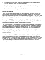
SBRGB PARTS LAYOUT DIAGRAM
SBRGB • 17
TROUBLESHOOTING GUIDE
If your Super Blinky does not work at all, re-check the following:
•
Correct orientation of U1, VR1, D1 (the LED), and battery hookup.
•
Correct polarity of the electrolytic capacitors.
•
Correct placement of D3.
•
Use an eye loupe to closely examine your parts placement for any pins
that may have overlapped two pads, solder joints that could be open, or
any large blobs of solder that maybe short across two or more pins.
•
Correct battery installation, and a good battery.
•
Replacement parts may be ordered directly from Ramsey Electronics, Inc.
First read the warranty in the back of the manual before you send your
unit back.
SBRGB SUPER BLINKY SPECIFICATIONS
- Input working voltage between 6 - 12 VDC @ 25 mA average (40 mA pk).
NOTE: 6 volt operation requires use of a jumper and removal of VR1.
- PCB Dimensions: 1.025” L x 0.825” W (max component height: 1/2”)
- Weight: 0.2 oz
- RGB LED (DIS-1024-105A): specifications on page 8
- Micro-controller type: PIC12C509SN (pre-programmed)
SBRGB • 18
The Ramsey Kit Warranty
Please read carefully BEFORE calling or writing in about your kit. Most problems can be
solved without contacting the factory.
Notice that this is not a "fine print" warranty. We want you to understand your rights and ours too!
All Ramsey kits will work if assembled properly. The very fact that your kit includes this new manual
is your assurance that a team of knowledgeable people have field-tested several "copies" of this kit
straight from the Ramsey Inventory. If you need help, please read through your manual carefully.
All information required to properly build and test your kit is contained within the pages!
1. DEFECTIVE PARTS: It's always easy to blame a part for a problem in your kit, Before you
conclude that a part may be bad, thoroughly check your work. Today's semiconductors and passive
components have reached incredibly high reliability levels, and it’s sad to say that our human
construction skills have not! But on rare occasions a sour component can slip through. All our kit
parts carry the Ramsey Electronics Warranty that they are free from defects for a full ninety (90)
days from the date of purchase. Defective parts will be replaced promptly at our expense. If you
suspect any part to be defective, please mail it to our factory for testing and replacement. Please
send only the defective part(s), not the entire kit. The part(s) MUST be returned to us in suitable
condition for testing. Please be aware that testing can usually determine if the part was truly
defective or damaged by assembly or usage. Don't be afraid of telling us that you 'blew-it', we're all
human and in most cases, replacement parts are very reasonably priced.
2. MISSING PARTS: Before assuming a part value is incorrect, check the parts listing carefully to
see if it is a critical value such as a specific coil or IC, or whether a RANGE of values is suitable
(such as "100 to 500 uF"). Often times, common sense will solve a mysterious missing part
problem. If you're missing five 10K ohm resistors and received five extra 1K resistors, you can
pretty much be assured that the '1K ohm' resistors are actually the 'missing' 10 K parts ("Hum-m-m,
I guess the 'red' band really does look orange!") Ramsey Electronics project kits are packed with
pride in the USA. If you believe we packed an incorrect part or omitted a part clearly indicated in
your assembly manual as supplied with the basic kit by Ramsey, please write or call us with
information on the part you need and proof of kit purchase.
3. FACTORY REPAIR OF ASSEMBLED KITS:
To qualify for Ramsey Electronics factory repair, kits MUST:
1. NOT be assembled with acid core solder or flux.
2. NOT be modified in any manner.
3. BE returned in fully-assembled form, not partially assembled.
4. BE accompanied by the proper repair fee. No repair will be undertaken until we have received
the MINIMUM repair fee (1/2 hour labor) of $25.00, or authorization to charge it to your
credit card account.
5. INCLUDE a description of the problem and legible return address. DO NOT send a separate
letter; include all correspondence with the unit. Please do not include your own hardware
such as non-Ramsey cabinets, knobs, cables, external battery packs and the like. Ramsey
Electronics, Inc., reserves the right to refuse repair on ANY item in which we find excessive
problems or damage due to construction methods. To assist customers in such situations,
Ramsey Electronics, Inc., reserves the right to solve their needs on a case-by-case basis.
The repair is $50.00 per hour, regardless of the cost of the kit. Please understand that our
technicians are not volunteers and that set-up, testing, diagnosis, repair and repacking and
paperwork can take nearly an hour of paid employee time on even a simple kit. Of course, if we find
that a part was defective in manufacture, there will be no charge to repair your kit (But please
realize that our technicians know the difference between a defective part and parts burned out or
damaged through improper use or assembly).
4. REFUNDS: You are given ten (10) days to examine our products. If you are not satisfied, you
may return your unassembled kit with all the parts and instructions and proof of purchase to the
factory for a full refund. The return package should be packed securely. Insurance is
recommended. Please do not cause needless delays, read all information carefully.
SBRGB • 19
SUPER BLINKY SMT PRACTICE KIT
Quick Reference Page Guide
Introduction ...................................... 4
Circuit Description ............................ 5
Parts List .......................................... 9
Assembly Steps ............................... 10
Using the SBRGB ............................ 16
Schematic Diagram ......................... 17
Parts Layout Diagram ...................... 17
Troubleshooting Guide .................... 18
Specifications................................... 18
Warranty .......................................... 19
REQUIRED TOOLS
• Soldering Iron Ramsey WLC100
• Thin Rosin Core Solder Ramsey RTS12
• Needle Nose Pliers Ramsey MPP4 or RTS05
• Small Diagonal Cutters Ramsey RTS04
<OR> Technician’s Tool Kit TK405
ADDITIONAL SUGGESTED ITEMS
Holder for PC Board/Parts Ramsey HH3
Desoldering Braid Ramsey RTS08
Digital Multimeter Ramsey M133
•
•
•
Price: $5.00
Ramsey Publication No. MSBRGB
Assembly and Instruction manual for:
RAMSEY MODEL NO. SBRGB
RAMSEY ELECTRONICS, INC.
590 Fishers Station Drive
Victor, New York 14564
Phone (585) 924-4560
SBRGB • 20
Fax (585) 924-4555
www.ramseykits.com
TOTAL SOLDER POINTS
45
ESTIMATED ASSEMBLY
TIME
Beginner .............. 2 hrs
Intermediate ........ 1 hrs
Advanced............. 0.5 hrs