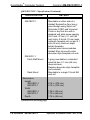
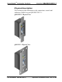
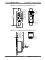
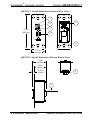
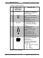
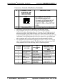
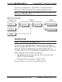
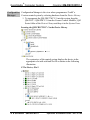
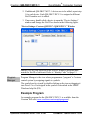
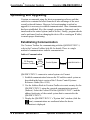
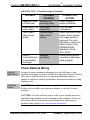
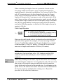
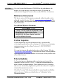
1
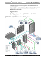
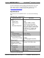
Crestron QM-FBCC-1 & QM-WCC-1 ® QuickMedia Computer Centers Operations & Installation Guide This document was prepared and written by the Technical Documentation department at: Crestron Electronics, Inc. 15 Volvo Drive Rockleigh, NJ 07647 1-888-CRESTRON Regulatory Compliance As of the date of manufacture, the QM-FBCC/WCC-1 has been tested and found to comply with specifications for CE marking and standards per EMC and Radiocommunications Compliance Labelling. Federal Communications Commission (FCC) Compliance Statement This device complies with part 15 of the FCC Rules. Operation is subject to the following conditions: (1) This device may not cause harmful interference and (2) this device must accept any interference received, including interference that may cause undesired operation. CAUTION: Changes or modifications not expressly approved by the manufacturer responsible for compliance could void the user’s authority to operate the equipment. NOTE: This equipment has been tested and found to comply with the limits for a Class B digital device, pursuant to part 15 of the FCC Rules. These limits are designed to provide reasonable protection against harmful interference in a residential installation. This equipment generates, uses and can radiate radio frequency energy and, if not installed and used in accordance with the instructions, may cause harmful interference to radio communications. However, there is no guarantee that interference will not occur in a particular installation. If this equipment does cause harmful interference to radio or television reception, which can be determined by turning the equipment off and on, the user is encouraged to try to correct the interference by one or more of the following measures: Reorient or relocate the receiving antenna Increase the separation between the equipment and receiver Connect the equipment into an outlet on a circuit different from that to which the receiver is connected Consult the dealer or an experienced radio/TV technician for help Industry Canada (IC) Compliance Statement This Class B digital apparatus complies with Canadian ICES-003. Cet appareil numérique de la classe B est conforme à la norme NMB-003 du Canada. All brand names, product names and trademarks are the property of their respective owners. ©2010 Crestron Electronics, Inc. Crestron QM-FBCC/WCC-1 QuickMedia® Computer Centers Contents QuickMedia® Computer Centers: QM-FBCC-1 & QM-WCC-1 1 Introduction ............................................................................................................................... 1 Features and Functions ................................................................................................ 1 Applications................................................................................................................. 4 Specifications .............................................................................................................. 5 Physical Description .................................................................................................... 8 Setup ........................................................................................................................................ 13 Network Wiring ......................................................................................................... 13 QuickMedia Wiring ................................................................................................... 13 Identity Code ............................................................................................................. 15 Installation ................................................................................................................. 16 Hardware Hookup ..................................................................................................... 19 Programming Software ............................................................................................................ 21 Earliest Version Software Requirements for the PC ......................................................... 21 Programming with Crestron SystemBuilder .............................................................. 21 Programming with SIMPL Windows ........................................................................ 21 Example Program ...................................................................................................... 23 Uploading and Upgrading ........................................................................................................ 24 Establishing Communication ..................................................................................... 24 Programs and Firmware ............................................................................................ 25 Program Checks ........................................................................................................ 25 QM Tools .................................................................................................................. 25 Problem Solving ...................................................................................................................... 26 Troubleshooting......................................................................................................... 26 Check Network Wiring.............................................................................................. 27 Reference Documents ................................................................................................ 29 Further Inquiries ........................................................................................................ 29 Future Updates .......................................................................................................... 29 Return and Warranty Policies .................................................................................................. 30 Merchandise Returns / Repair Service ...................................................................... 30 CRESTRON Limited Warranty................................................................................. 30 Operations & Installation Guide – DOC. 6716B Contents i Crestron QM-FBCC/WCC-1 QuickMedia® Computer Centers ® QuickMedia Computer Centers: QM-FBCC-1 & QM-WCC-1 Introduction Crestron® MediaManager is a comprehensive family of affordable products fusing high performance AV signal distribution, device control and facility-wide system management. MediaManager simplifies the art of Pro AV system design and installation with complete hardware, software and low-cost wiring solutions. Whether installing a single boardroom or a campus-wide network of AV systems, MediaManager delivers power and value far beyond conventional products and designs. Features and Functions Single cable signal transmission up to 450 feet (137 meters) DB15HD RGB computer input Stereo audio input Video input signal sensing QuickMedia transport Cresnet® communications Low-cost, quick and easy installation Performs Video signal format management via EDID Easy setup using Creston SystemBuilder™ software QM-FBCC-1: Floor box mountable QuickMedia computer interface Fits Hubbell SystemOne floor boxes and poke-throughs Compatible with Hubbell Style Line® and Leviton decorator style faceplate cut-outs (Continued on following page) Operations & Installation Guide – DOC. 6716B QuickMedia®: QM-FBCC/WCC-1 1 QuickMedia® Computer Centers Crestron QM-FBCC/WCC-1 Features and Functions (Continued) QM-WCC-1: Wall mount QuickMedia computer interface Integrates with Crestron C2N-CBD and C2N-DB Series Keypads Installs alongside third-party LAN jacks and other devices Available in white or black The QM-FBCC-1 QuickMedia® Floor Box Computer Center is designed for mounting in a variety of popular floor boxes and the QM-WCC-1 QuickMedia Wall Plate Computer Center provides a simple wall mount computer interface solution for any MediaManager system, including applications ranging from small conference rooms to large banquet halls and auditoriums. For simplicity within this guide, the term “QM-FBCC/WCC-1” is used except where noted. Floor Box Computer Interface (QM-FBCC-1 only) The QM-FBCC-1 installs cleanly in a Hubbell SystemOne floor box or poke-through using their Style Line® Sub-plate and Universal Cover. Its slim dimensions and standard screw spacing may also make it suitable for use with a variety of other floor box systems. An adhesive insert is included to fit Hubbell Style Line and Leviton decorator style faceplate cutouts. Each QM-FBCC-1 provides a single RGB input with stereo audio to accept a connection from a computer or other RGB source. Built-in signal sensing can be utilized to trigger automatic input selection and power control. Wiring for the QM-FBCC-1 is extremely simple requiring just a single CresCAT®QM cable (sold separately). Wall Mount Computer Interface (QM-WCC-1 only) The QM-WCC-1 installs cleanly in a standard electrical box using a decorator style faceplate (not supplied). A single RGB input with stereo audio is provided to accept a connection from a computer or other RGB source. 2 QuickMedia®: QM-FBCC/WCC-1 Operations & Installation Guide – DOC. 6716B Crestron QM-FBCC/WCC-1 QuickMedia® Computer Centers Connectivity for LAN and other signals can easily be added by ganging the QM-WCC-1 together with other third-party wall plate devices. A Crestron C2N-CDB or C2N-DB series keypad may also be installed for a truly complete interface and control solution. Wiring for the QM-WCC-1 is extremely simple, requiring just a single CresCAT-QM cable (sold separately). Built-in signal sensing can be utilized to trigger automatic input selection and power control. QuickMedia® Transport Using the revolutionary Crestron QuickMedia (QM) transport, input signals are transmitted from the QM-FBCC/WCC-1 to any QuickMedia receiver or distribution center over a single inexpensive CAT5e type cable. Computer resolutions up to 1920 x 1200 pixels at 60 Hz are supported over cable runs up to 450 feet (137 meters). Audio signals are transmitted digitally with high performance 24-bit resolution. QuickMedia dramatically simplifies system design and installation, affording a higher level of performance at a lower overall cost. NOTE: For QuickMedia wiring use CresCAT-QM, CresCAT-IM or quality CAT5e/CAT6 cable with a delay skew of ≤ 15 ns per 328 feet (100 meters); the maximum aggregate cable length and delay skew between any QM transmitter (origination point) and QM receiver (endpoint) is 450 feet (137 meters) and 22 ns; a maximum of two QM midpoint devices may be inserted in a given QM signal path; exceptions apply, refer to each respective product manual for details. MediaManager System Integration Whether using just one floor box or wall plate computer center or several, complete system operation can be made transparent to the end user with all signal routing occurring smoothly under the command of the MediaManager control system. Complete MediaManager systems are easy to design, program and adjust from start to finish using Crestron SystemBuilder™ software. EDID Format Management The QM-FBCC/WCC-1 allows for management of the EDID (Extended Display Identification Data) information sent to the connected source. Using Crestron Toolbox™ software, the format and resolution Operations & Installation Guide – DOC. 6716B QuickMedia®: QM-FBCC/WCC-1 3 QuickMedia® Computer Centers Crestron QM-FBCC/WCC-1 capabilities of each device can be assessed and managed through the QM-FBCC/WCC-1, ensuring reliable operation by instructing sources to output only the resolutions and formats that can be handled by the displays and system wiring. Applications The following diagram shows a QM-FBCC-1 and QM-WCC-1 in a lecture hall application. QM-FBCC-1 and QM-WCC-1 in a Lecture Hall Application 4 QuickMedia®: QM-FBCC/WCC-1 Operations & Installation Guide – DOC. 6716B Crestron QM-FBCC/WCC-1 QuickMedia® Computer Centers For more information on this and other QM applications, refer to the latest revision of the Crestron MediaManager Applications Guide (Doc. 6244), which is available from the Crestron Web site (www.crestron.com/manuals). Specifications Specifications for the QM-FBCC/WCC-1 are listed in the following table. QM-FBCC/WCC-1 Specifications SPECIFICATION Video Signal Types RGB Formats Gain Maximum Resolution Audio A-D Conversion Frequency Response Power Requirements Cresnet Power Usage Default Net ID Minimum 2-Series Control System Update File1, 2 Environmental Temperature Humidity Heat Dissipation DETAILS RGB RGBHV, RGBS or RGsB 0 dB (75 ohms terminated) 1920 x 1200 @ 60 Hz (at unity gain) with maximum cable length of 450 feet (137 meters) and maximum compensation at receiver 24-bit, 48 kHz 20 Hz to 20 kHz 4 Watts (0.17 Amps @ 24 Volts DC) 8E Version 3.155.1240 or later 41º to 104º F (5º to 40º C) 10% to 90% RH (non-condensing) 14 BTU/Hr (Continued on following page) Operations & Installation Guide – DOC. 6716B QuickMedia®: QM-FBCC/WCC-1 5 QuickMedia® Computer Centers Crestron QM-FBCC/WCC-1 QM-FBCC/WCC-1 Specifications (Continued) SPECIFICATION DETAILS Enclosure QM-FBCC-1 Mountable on either side of a Hubbell SystemOne floor box or poke-through using Style Line® Sub-plate (S1SP) and Universal Cover or any floor box with a standard wall plate screw spacing (3.81 inch, 97 mm), 2.1 inch (54 mm) high x 0.8 inch (21 mm) wide minimum faceplate cut-out and 2.1 inch (54 mm) minimum depth behind faceplate; Included insert accommodates Hubbell Style Line and Leviton decorator style faceplate cut-outs QM-WCC-1 Flush Wall Mount 1-gang mountable in a standard electrical box, 2.1 inch (54 mm) deep minimum; Requires decorator style faceplate (not included) Mountable to a single 19-inch EIA rack rail Rack Mount Dimensions Height QM-FBCC-1 QM-WCC-1 Width QM-FBCC-1 QM-WCC-1 Depth 4.14 in (105 mm) 4.12 in (105 mm) 1.30 in (33 mm) 1.72 in (44 mm) 1.74 in (44 mm) (Continued on following page) 6 QuickMedia®: QM-FBCC/WCC-1 Operations & Installation Guide – DOC. 6716B Crestron QM-FBCC/WCC-1 QuickMedia® Computer Centers QM-FBCC/WCC-1 Specifications (Continued) SPECIFICATION Weight QM-FBCC-1 QM-WCC-1 Available Models QM-FBCC-1 QM-WCC-1-B-T QM-WCC-1-W-T Available Accessories CresCAT-IM CresCAT-QM Cresnet DETAILS 6 oz (155 g) 8 oz (210 g) QuickMedia Floor Box Computer Center, Black QuickMedia Wall Plate Computer Center, Single Input, Black QuickMedia Wall Plate Computer Center, Single Input, White iMedia Cable QuickMedia Cable Cresnet Control Cable 1. The latest software versions can be obtained from the Crestron Web site. Refer to the NOTE following these footnotes. 2. Crestron 2-Series control systems include the AV2 and PRO2. Consult the latest Crestron Product Catalog for a complete list of 2-Series control systems. NOTE: Crestron software and any files on the Web site are for authorized Crestron dealers and Crestron Authorized Independent Programmers (CAIP) only. New users may be required to register to obtain access to certain areas of the site (including the FTP site). Operations & Installation Guide – DOC. 6716B QuickMedia®: QM-FBCC/WCC-1 7 QuickMedia® Computer Centers Crestron QM-FBCC/WCC-1 Physical Description This section provides information on the connections, controls and indicators available on your QM-FBCC/WCC-1. QM-FBCC-1 Physical View QM-WCC-1 Physical View 8 QuickMedia®: QM-FBCC/WCC-1 Operations & Installation Guide – DOC. 6716B Crestron QM-FBCC/WCC-1 QuickMedia® Computer Centers QM-FBCC-1 Overall Dimensions (Front and Rear Views) 1 5 2 3 4.14 in (105 mm) 4 6 1.30 in (33 mm) QM-FBCC-1 Overall Dimensions (Side and Bottom Views) 1.74 in (44mm) 1.55 in (39 mm) 0.13 in (3 mm) 6 7 Operations & Installation Guide – DOC. 6716B QuickMedia®: QM-FBCC/WCC-1 9 QuickMedia® Computer Centers Crestron QM-FBCC/WCC-1 QM-WCC-1 Overall Dimensions (Front and Rear Views) 1 5 2 3 4.12 in (105 mm) 4 6 1.72 in (44 mm) QM-WCC-1 Overall Dimensions (Side and Bottom Views) 1.74 in (44 mm) 1.50 in (38 mm) 0.19 in (5 mm) 6 7 10 QuickMedia®: QM-FBCC/WCC-1 Operations & Installation Guide – DOC. 6716B Crestron QM-FBCC/WCC-1 QuickMedia® Computer Centers Connectors, Controls & Indicators # CONNECTORS1, CONTROLS & INDICATORS DESCRIPTION 1 PWR LED 2 AUDIO 3 NET LED 4 PC 5 NET (1) Green LED, indicates 24 Volts DC power supplied from Cresnet network (1) 3.5 mm TRS mini phone jack; Unbalanced stereo line level audio input; Input impedance: 10 kΩ; Maximum input level: 1 Vrms (1) Yellow LED, indicates communication with Cresnet system (1) DB15HD female; RGB(VGA) input; Formats: RGBHV, RGBS, RGsB; Input impedance: 75 Ω Sync impedance: 1 kΩ Maximum input: level: 1 Vp-p Maximum sync level: 5 Vp-p Signal sensing on H-SYNC only (1) 4-pin 3.5 mm detachable terminal block; Cresnet slave port; Connects to Cresnet control network via CresCAT-QM or Cresnet cable 24: Power (24 Volts DC) Y: Data Z: Data G: Ground (Continued on following page) Operations & Installation Guide – DOC. 6716B QuickMedia®: QM-FBCC/WCC-1 11 QuickMedia® Computer Centers Crestron QM-FBCC/WCC-1 Connectors, Controls, & Indicators (Continued) # CONNECTORS1, CONTROLS & INDICATORS DESCRIPTION 6 QM2, 3 (1) 8-wire RJ-45 female, QuickMedia output port; Connects to QM input port of any QuickMedia device via CresCAT-QM or CresCAT-IM cable (1) Flying lead, grounding wire 1 7 8 Grounding Wire 1. An interface connector for the NET port is provided with the unit. 2. For QuickMedia wiring, use CresCAT-QM, CresCAT-IM or quality CAT5e/CAT6 cable with a delay skew of ≤ 15 ns per 328 feet (100 meters); the maximum aggregate cable length and delay skew between any QM transmitter (origination point) and QM receiver (endpoint) is 450 feet (137 meters) and 22 ns; a maximum of two QM midpoint devices may be inserted in a given QM signal path; exceptions apply, refer to each respective product manual for details. 3. The eight-pin RJ-45 QuickMedia transport port accepts CAT5E/CAT6 carrying audio, video and microphone signals. The QM input port conforms to the 568B wiring standard. Refer to the following table for connector pinouts. RJ-45 PIN NUMBER WIRE COLORS (EIA 568B) QM ASSIGNMENT: RGB QM ASSIGNMENT: COMPOSITE, S-VIDEO, COMPONENT AND AUDIO 1 WHITE/ORANGE - RGB RED - CHROMINANCE (- Pr) 2 ORANGE + RGB RED + CHROMINANCE (+ Pr) 3 WHITE/GREEN - RGB GREEN - LUMINANCE (- Y) 4 BLUE + DIGITAL AUDIO + DIGITAL AUDIO 5 WHITE/BLUE - DIGITAL AUDIO - DIGITAL AUDIO 6 GREEN + RGB GREEN + LUMINANCE (+ Y) 7 WHITE/BROWN - RGB BLUE - COMPOSITE (- Pb) 8 BROWN + RGB BLUE + COMPOSITE (+ Pb) 12 QuickMedia®: QM-FBCC/WCC-1 Operations & Installation Guide – DOC. 6716B Crestron QM-FBCC/WCC-1 QuickMedia® Computer Centers Setup Network Wiring When wiring the Cresnet® network, consider the following: Use Crestron Certified Wire. Use Crestron power supplies for Crestron equipment. Provide sufficient power to the system. CAUTION: Insufficient power can lead to unpredictable results or damage to the equipment. Please use the Crestron Power Calculator to help calculate how much power is needed for the system (www.crestron.com/calculators). For networks with 20 or more devices, use a Cresnet Hub/Repeater (CNXHUB) to maintain signal quality. For more details, refer to “Check Network Wiring” which starts on page 27. QuickMedia Wiring The Crestron QuickMedia cable (sold under the name “CresCAT-QM”) contains one CAT5E cable and one Cresnet cable in Siamese jackets. Installation of any QM device is as simple as installing CresCAT-QM wires from the output of one device to the input of another. Installations are flexible, affordable and fast. For more information, refer to the latest revision of the Crestron MediaManager Applications Guide (Doc. 6244), which is available from the Crestron Web site. Operations & Installation Guide – DOC. 6716B QuickMedia®: QM-FBCC/WCC-1 13 QuickMedia® Computer Centers Crestron QM-FBCC/WCC-1 CresCAT-QM Cable CresCAT-QM Cable NOTE: Do not untwist the two wires in a single pair for more than 1/31/2” (8–12 mm) when making a connection. The twists are critical to canceling out interference between the wires. The aggregate cable length of a signal path originating at a QM-FBCC/WCC-1 and terminating at a QM receiver must not exceed 450 feet (137 meters). Video signals may experience a loss of quality over very long lengths of cable. This phenomenon is due to the added resistance and capacitance of longer cable lengths and is not peculiar to either Crestron and/or QuickMedia systems. To ensure sufficient bandwidth, the maximum aggregate cable length should not exceed 450 feet. The use of lower-resolution signals may allow increased cable length but must be tested by the installer with the sources to be used. The QM pin assignment is based on the EIA/TIA 568B RJ-45 Jack standard. NOTE: When using CresCAT-QM wiring, four additional wires are included for making Cresnet connections. When connecting multiple QM devices, the route between a QM origination point (transmitter) and a QM endpoint (receiver) cannot have 14 QuickMedia®: QM-FBCC/WCC-1 Operations & Installation Guide – DOC. 6716B Crestron QM-FBCC/WCC-1 QuickMedia® Computer Centers more than two midpoints (e.g. QM-MD7x2 or other QM switchers). Refer to the following diagram when configuring a QM network. NOTE: The aggregate length from transmitter to receiver cannot have a delay skew of more than 22 ns. QM Network Topology Identity Code NOTE: This device does not support TSID. The Net ID of the QM-FBCC/WCC-1 has been factory set to 8E. The Net IDs of multiple QM-FBCC/WCC-1 devices in the same system must be unique. Net IDs are changed from a personal computer (PC) via Crestron Toolbox™ (refer to “Establishing Communication” on page 24). When setting the Net ID, consider the following: The Net ID of each unit must match an ID code specified in the SIMPL™ Windows program. Each network device must have a unique Net ID. For more details, refer to the Crestron Toolbox help file. Operations & Installation Guide – DOC. 6716B QuickMedia®: QM-FBCC/WCC-1 15 QuickMedia® Computer Centers Crestron QM-FBCC/WCC-1 Installation The QM-FBCC/WCC-1 should be used in a well-ventilated area. The venting holes should not be obstructed under any circumstances. To prevent overheating, do not operate this product in an area that exceeds the environmental temperature range listed in the table of specifications. The following tools and accessories are required for installation of a QM-FBCC/WCC-1: Hubbell® SystemOne® floor box S1SP plate (for QM-FBCC-1, not supplied) Standard 1-gang electrical box (for QM-WCC-1, not supplied) Decorator style or equivalent wall plate (for QM-WCC-1, not supplied) Flat head screwdriver (not supplied) Two #06-32 x 1” screws (included) Insert, black or white (included) After Cresnet and QM wiring has been installed and verified, use the following procedure to install the QM-FBCC/WCC-1. 1. Turn system power OFF. 2. Connect the Cresnet and QM cables to the QM-FBCC/WCC-1’s Cresnet and QM ports, respectively. 3. Attach the QM-FBCC/WCC-1 to the floor box or electrical box using the two supplied #06-32 x 1” screws. CAUTION: Excess wire that is pinched between the QM-FBCC/WCC-1 and the floor box or electrical box could short out. Make sure all excess wire is completely inside the floor box or electrical box and not between the box and the QM-FBCC/WCC-1. 4. For the QM-WCC-1, attach the wall plate using the screws that came with the wall plate. 5. Remove the backing, which covers the adhesive, on the insert and attach the insert to the QM-FBCC/WCC-1, as shown in the illustrations on the following pages. 6. Turn system power ON. 16 QuickMedia®: QM-FBCC/WCC-1 Operations & Installation Guide – DOC. 6716B Crestron QM-FBCC/WCC-1 QuickMedia® Computer Centers QM-FBCC-1 Installation (Two QM-FBCC-1s Shown) Insert, Black (4508384) Screws (2) #06-32 x 1" (2013235) Hubbell® SystemOne® Floor Box S1SP Plate (not supplied) QM-FBCC-1 Operations & Installation Guide – DOC. 6716B QuickMedia®: QM-FBCC/WCC-1 17 QuickMedia® Computer Centers Crestron QM-FBCC/WCC-1 QM-WCC-1 Installation 1-Gang Wall Box (not supplied) QM-WCC-1 Screws (2) #06-32 x 1" (2013235) Wall Plate with Hardware (not supplied) Insert, Black (4508384) or Insert, White (4508383) 18 QuickMedia®: QM-FBCC/WCC-1 Operations & Installation Guide – DOC. 6716B QuickMedia® Computer Centers Crestron QM-FBCC/WCC-1 Hardware Hookup Make the necessary connections as called out in the illustration that follows this paragraph. Refer to “Network Wiring” on page 13 before attaching the 4-position terminal block connector. Apply power after all connections have been made. When making connections to the QM-FBCC/WCC-1, use Crestron power supplies for Crestron equipment. Hardware Connections for the QM-FBCC-1 (Front and Rear Views) AUDIO: Unbalanced Stereo Audio Input PC: VGA Video From PC NET: To Control System And Other Cresnet Devices QM: QuickMedia Port Carries Aaudio, Video, RGB And MIC Output Over CAT5 Hardware Connections for the QM-FBCC-1 (Side and Bottom Views) Ground Operations & Installation Guide – DOC. 6716B QM: QuickMedia Port Carries Aaudio, Video, RGB And MIC Output Over CAT5 QuickMedia®: QM-FBCC/WCC-1 19 QuickMedia® Computer Centers Crestron QM-FBCC/WCC-1 Hardware Connections for the QM-WCC-1 (Front and Rear Views) AUDIO: Unbalanced Stereo Audio Input PC: VGA Video From PC NET: To Control System And Other Cresnet Devices QM: QuickMedia Port Carries Aaudio, Video, RGB And MIC Output Over CAT5 Hardware Connections for the QM-WCC-1 (Side and Bottom Views) QM: QuickMedia Port Carries Aaudio, Video, RGB And MIC Output Over CAT5 Ground NOTE: Ensure the unit is properly grounded by connecting the ground wire to an earth ground (building steel). NOTE: For optimum performance, Crestron strongly recommends using CresCAT-QM cable, available from Crestron. Other high-quality/low skew CAT5e/CAT6 wiring may also be used with varying performance. NOTE: The maximum continuous current from equipment under any external load conditions shall not exceed a current limit that is suitable for the minimum wire gauge used in interconnecting cables. The ratings on the connecting unit's supply input should be considered to prevent overloading the wiring. 20 QuickMedia®: QM-FBCC/WCC-1 Operations & Installation Guide – DOC. 6716B Crestron QM-FBCC/WCC-1 QuickMedia® Computer Centers Programming Software Have a question or comment about Crestron software? Answers to frequently asked questions (FAQs) can be viewed in the Online Help section of the Crestron Web site. To post a question or view questions you have submitted to Crestron’s True Blue Support, log in at http://support.crestron.com. First-time users will need to establish a user account. Earliest Version Software Requirements for the PC NOTE: Crestron recommends that you use the latest software to take advantage of the most recently released features. The latest software is available from the Crestron Web site (www.crestron.com/software). Crestron has developed an assortment of Windows-based software tools to develop a Cresnet system. You can create a program to control the QM-FBCC/WCC-1 using the Crestron programming tools SystemBuilder™ or SIMPL Windows. For the minimum recommended software versions, visit the Version Tracker page of the Crestron Web site (www.crestron.com/versiontracker). Programming with Crestron SystemBuilder Crestron SystemBuilder is the easiest method of programming but does not offer as much flexibility as SIMPL Windows. For additional details, download SystemBuilder from the Crestron Web site and examine the extensive help file. Programming with SIMPL Windows NOTE: While SIMPL Windows can be used to program the QM-FBCC/WCC-1, it is recommended to use SystemBuilder for configuring a QuickMedia system. SIMPL Windows is Crestron’s premier software for programming Crestron control systems. It is organized into two separate but equally important “Managers”. Operations & Installation Guide – DOC. 6716B QuickMedia®: QM-FBCC/WCC-1 21 QuickMedia® Computer Centers Crestron QM-FBCC/WCC-1 Configuration Configuration Manager is the view where programmers “build” a Crestron control system by selecting hardware from the Device Library. Manager 1. To incorporate the QM-FBCC/WCC-1 into the system, drag the QM-WCC-1/QM-FBCC-1 from the Cresnet Control Modules | QM Series folder of the Device Library and drop it in the System Views. Locating the QM-FBCC/WCC-1 in the Device Library The system tree of the control system displays the device in the appropriate slot with a default Net ID as shown in the following illustration. C2Net Device, Slot 9 22 QuickMedia®: QM-FBCC/WCC-1 Operations & Installation Guide – DOC. 6716B Crestron QM-FBCC/WCC-1 QuickMedia® Computer Centers 2. If additional QM-FBCC/WCC-1 devices are to be added, repeat step 1 for each device. Each QM-FBCC/WCC-1 is assigned a different Net ID number as it is added. 3. If necessary, double click a device to open the “Device Settings” window and change the Net ID as shown in the following figure. “Device Settings: Crestron QM-WCC-1/QM-FBCC-1” Window NOTE: The ID code specified in the SIMPL Windows program must match the Net ID of each unit. Refer to “Identity Code” on page 15. Program Manager Program Manager is the view where programmers “program” a Crestron control system by assigning signals to symbols. The symbol can be viewed by double clicking on the icon or dragging it into Detail View. Each signal in the symbol is described in the SIMPL Windows help file (F1). Example Program An example program for the QM-FBCC/WCC-1 is available from the Crestron Web site (www.crestron.com/exampleprograms). Operations & Installation Guide – DOC. 6716B QuickMedia®: QM-FBCC/WCC-1 23 QuickMedia® Computer Centers Crestron QM-FBCC/WCC-1 Uploading and Upgrading Crestron recommends using the latest programming software and that each device contains the latest firmware to take advantage of the most recently released features. However, before attempting to upload or upgrade it is necessary to establish communication. Once communication has been established, files (for example, programs or firmware) can be transferred to the control system (and/or device). Finally, program checks can be performed (such as changing the device ID or creating an IP table) to ensure proper functioning. Establishing Communication Use Crestron Toolbox for communicating with the QM-FBCC/WCC-1; refer to the Crestron Toolbox help file for details. There is a single method of communication: indirect communication. Indirect Communication Serial, PC Running Crestron Toolbox LAN or USB Control System QM-FBCC/WCC-1 Cresnet QM-FBCC/WCC-1 connects to control system via Cresnet: 1. Establish communication between the PC and the control system as described in the latest version of the 2-Series Control Systems Reference Guide (Doc. 6256). 2. Use the Address Book in Crestron Toolbox to create an entry for the QM-FBCC/WCC-1 using the expected communication protocol (Indirect). Select the Cresnet ID of the QM-FBCC/WCC-1 and the address book entry of the control system that is connected to the QM-FBCC/WCC-1. 3. Display the QM-FBCC/WCC-1’s “System Info” window (click the icon); communications are confirmed when the device information is displayed. 24 QuickMedia®: QM-FBCC/WCC-1 Operations & Installation Guide – DOC. 6716B Crestron QM-FBCC/WCC-1 QuickMedia® Computer Centers Programs and Firmware Program or firmware files may be distributed from programmers to installers or from Crestron to dealers. Firmware upgrades are available from the Crestron Web site as new features are developed after product releases. One has the option to upload programs via the programming software or to upload and upgrade via the Crestron Toolbox. For details on uploading and upgrading, refer to the SIMPL Windows help file or the Crestron Toolbox help file. SIMPL Windows If a SIMPL Windows program is provided, it can be uploaded to the control system using SIMPL Windows or Crestron Toolbox. Firmware Check the Crestron Web site to find the latest firmware. (New users may be required to register to obtain access to certain areas of the site, including the FTP site.) Upgrade QM-FBCC/WCC-1 firmware via Crestron Toolbox. 1. Establish communication with the QM-FBCC/WCC-1 and display the “System Info” window. 2. Select Functions | Firmware… to upgrade the QM-FBCC/WCC-1 firmware. Program Checks Using Crestron Toolbox, display the network device tree (Tools | Network Device Tree) to show all network devices connected to the control system. Right-click on the QM-FBCC/WCC-1 to display actions that can be performed on the QM-FBCC/WCC-1. QM Tools In the Crestron Toolbox Address Book, select the QM-FBCC/WCC-1. Then use the QM Tools to configure audio/video settings, including EDID. Refer to the help file for details. Operations & Installation Guide – DOC. 6716B QuickMedia®: QM-FBCC/WCC-1 25 QuickMedia® Computer Centers Crestron QM-FBCC/WCC-1 Problem Solving Troubleshooting The following table provides corrective action for possible trouble situations. If further assistance is required, please contact a Crestron customer service representative. QM-FBCC/WCC-1 Troubleshooting TROUBLE POSSIBLE CAUSE(S) CORRECTIVE ACTION Device does not function. Device is not communicating with the network. Use Crestron Toolbox to poll the network. Verify network connection to the device. Use a Crestron power source. Verify connections. Device is not receiving power from a Crestron power source. Device is not receiving sufficient power. Device Net ID does not match Net ID in SIMPL Windows program. Device Net ID is same as another device’s Net ID. Use the Crestron Power Calculator to help calculate how much power is needed for the system. Verify Net ID matches Net ID in SIMPL Windows program. Assign a different Net ID, to match the Net ID in SIMPL Windows program. (Continued on following page) 26 QuickMedia®: QM-FBCC/WCC-1 Operations & Installation Guide – DOC. 6716B QuickMedia® Computer Centers Crestron QM-FBCC/WCC-1 QM-FBCC/WCC-1 Troubleshooting (Continued) TROUBLE POSSIBLE CAUSE(S) PWR LED does not illuminate. Intermittent or no audio output. Poor RGB or video image quality. Device is not receiving power. Poor cable connection. Incorrect peak and/or boost setting. Loss of functionality due to electrostatic discharge. Improper grounding. CORRECTIVE ACTION Verify Cresnet is properly attached. Verify all cable connections. Adjust QM-RMCRX-BA peak or boost controls until image quality is improved. For more information, refer to the latest revision of the QM-RMCRX-BA Operations Guide (Doc. 6332). Check that all ground connections have been made properly. Check Network Wiring Use the Right Wire In order to ensure optimum performance over the full range of your installation topology, Crestron Certified Wire and only Crestron Certified Wire may be used. Failure to do so may incur additional charges if support is required to identify performance deficiencies because of using improper wire. Calculate Power CAUTION: Use only Crestron power supplies for Crestron equipment. Failure to do so could cause equipment damage or void the Crestron warranty. CAUTION: Provide sufficient power to the system. Insufficient power can lead to unpredictable results or damage to the equipment. Please use the Crestron Power Calculator to help calculate how much power is needed for the system (www.crestron.com/calculators). Operations & Installation Guide – DOC. 6716B QuickMedia®: QM-FBCC/WCC-1 27 QuickMedia® Computer Centers Crestron QM-FBCC/WCC-1 When calculating the length of wire for a particular Cresnet run, the wire gauge and the Cresnet power usage of each network unit to be connected must be taken into consideration. Use Crestron Certified Wire only. If Cresnet units are to be daisy-chained on the run, the Cresnet power usage of each network unit to be daisy-chained must be added together to determine the Cresnet power usage of the entire chain. If the unit is home-run from a Crestron system power supply network port, the Cresnet power usage of that unit is the Cresnet power usage of the entire run. The wire gauge and the Cresnet power usage of the run should be used in the following equation to calculate the cable length value on the equation’s left side. Cable Length Equation 40,000 L< RxP Where: L = Length of run (or chain) in feet R = 6 Ohms (Crestron Certified Wire: 18 AWG (0.75 mm2 )) or 1.6 Ohms (Cresnet HP: 12 AWG (4 mm2 )) P = Cresnet power usage of entire run (or chain) Make sure the cable length value is less than the value calculated on the right side of the equation. For example, a Cresnet run using 18 AWG Crestron Certified Wire and drawing 20 watts should not have a length of run more than 333 feet (101 meters). If Cresnet HP is used for the same run, its length could extend to 1250 feet (381 meters). NOTE: All Crestron certified Cresnet wiring must consist of two twisted pairs. One twisted pair is the +24V conductor and the GND conductor and the other twisted pair is the Y conductor and the Z conductor. Strip and Tin Wire When daisy-chaining Cresnet units, strip the ends of the wires carefully to avoid nicking the conductors. Twist together the ends of the wires that share a pin on the network connector and tin the twisted connection. Apply solder only to the ends of the twisted wires. Avoid tinning too far up the wires or the end becomes brittle. Insert the tinned connection into the Cresnet connector and tighten the retaining screw. Repeat the procedure for the other three conductors. 28 QuickMedia®: QM-FBCC/WCC-1 Operations & Installation Guide – DOC. 6716B Crestron QM-FBCC/WCC-1 Add Hubs QuickMedia® Computer Centers Use of a Cresnet Hub/Repeater (CNXHUB) is advised whenever the number of Cresnet devices on a network exceeds 20 or when the combined total length of Cresnet cable exceeds 3000 feet (914 meters). Reference Documents The latest version of all documents mentioned within the guide can be obtained from the Crestron Web site (www.crestron.com/manuals). This link will provide a list of product manuals arranged in alphabetical order by model number. List of Related Reference Documents DOCUMENT TITLE 2-Series Control Systems Reference Guide MediaManager Applications Guide QM-RMCRX-BA Room Media Controller and QuickMedia Receiver Further Inquiries If you cannot locate specific information or have questions after reviewing this guide, please take advantage of Crestron's award winning customer service team by calling Crestron at 1-888-CRESTRON [1-888-273-7876]. You can also log onto the online help section of the Crestron Web site (www.crestron.com/onlinehelp) to ask questions about Crestron products. First-time users will need to establish a user account to fully benefit from all available features. Future Updates As Crestron improves functions, adds new features and extends the capabilities of the QM-FBCC/WCC-1, additional information may be made available as manual updates. These updates are solely electronic and serve as intermediary supplements prior to the release of a complete technical documentation revision. Check the Crestron Web site periodically for manual update availability and its relevance. Updates are identified as an “Addendum” in the Download column. Operations & Installation Guide – DOC. 6716B QuickMedia®: QM-FBCC/WCC-1 29 QuickMedia® Computer Centers Crestron QM-FBCC/WCC-1 Return and Warranty Policies Merchandise Returns / Repair Service 1. No merchandise may be returned for credit, exchange or service without prior authorization from CRESTRON. To obtain warranty service for CRESTRON products, contact an authorized CRESTRON dealer. Only authorized CRESTRON dealers may contact the factory and request an RMA (Return Merchandise Authorization) number. Enclose a note specifying the nature of the problem, name and phone number of contact person, RMA number and return address. 2. Products may be returned for credit, exchange or service with a CRESTRON Return Merchandise Authorization (RMA) number. Authorized returns must be shipped freight prepaid to CRESTRON, 6 Volvo Drive, Rockleigh, N.J. or its authorized subsidiaries, with RMA number clearly marked on the outside of all cartons. Shipments arriving freight collect or without an RMA number shall be subject to refusal. CRESTRON reserves the right in its sole and absolute discretion to charge a 15% restocking fee plus shipping costs on any products returned with an RMA. 3. Return freight charges following repair of items under warranty shall be paid by CRESTRON, shipping by standard ground carrier. In the event repairs are found to be non-warranty, return freight costs shall be paid by the purchaser. CRESTRON Limited Warranty CRESTRON ELECTRONICS, Inc. warrants its products to be free from manufacturing defects in materials and workmanship under normal use for a period of three (3) years from the date of purchase from CRESTRON, with the following exceptions: disk drives and any other moving or rotating mechanical parts, pan/tilt heads and power supplies are covered for a period of one (1) year; touchscreen display and overlay components are covered for 90 days; batteries and incandescent lamps are not covered. This warranty extends to products purchased directly from CRESTRON or an authorized CRESTRON dealer. Purchasers should inquire of the dealer regarding the nature and extent of the dealer's warranty, if any. CRESTRON shall not be liable to honor the terms of this warranty if the product has been used in any application other than that for which it was intended or if it has been subjected to misuse, accidental damage, modification or improper installation procedures. Furthermore, this warranty does not cover any product that has had the serial number altered, defaced or removed. This warranty shall be the sole and exclusive remedy to the original purchaser. In no event shall CRESTRON be liable for incidental or consequential damages of any kind (property or economic damages inclusive) arising from the sale or use of this equipment. CRESTRON is not liable for any claim made by a third party or made by the purchaser for a third party. CRESTRON shall, at its option, repair or replace any product found defective, without charge for parts or labor. Repaired or replaced equipment and parts supplied under this warranty shall be covered only by the unexpired portion of the warranty. Except as expressly set forth in this warranty, CRESTRON makes no other warranties, expressed or implied, nor authorizes any other party to offer any warranty, including any implied warranties of merchantability or fitness for a particular purpose. Any implied warranties that may be imposed by law are limited to the terms of this limited warranty. This warranty statement supersedes all previous warranties. Trademark Information All brand names, product names and trademarks are the sole property of their respective owners. Windows is a registered trademark of Microsoft Corporation. Windows 95/98/Me/XP/Vista/7 and Windows NT/2000 are trademarks of Microsoft Corporation. 30 QuickMedia®: QM-FBCC/WCC-1 Operations & Installation Guide – DOC. 6716B Crestron QM-FBCC/WCC-1 QuickMedia® Computer Centers This page is intentionally left blank. Operations & Installation Guide – DOC. 6716B QuickMedia®: QM-FBCC/WCC-1 31 Crestron Electronics, Inc. 15 Volvo Drive Rockleigh, NJ 07647 Tel: 888.CRESTRON Fax: 201.767.7576 www.crestron.com Operations & Installation Guide – DOC. 6716B (2021900) 09.10 Specifications subject to change without notice.