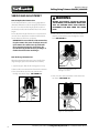
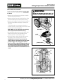
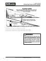
1
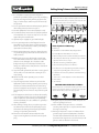
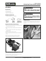
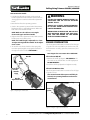
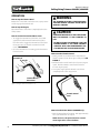
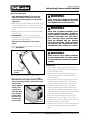
Operator's Manual Rolling String Trimmer 600050V 600050B OM600050V/OM600050B R091109 © 2009 Ardisam, Inc. All Rights Reserved. Operator's Manual Rolling String Trimmer 600050V, 600050B 1-YEAR Limited Warranty Terms and Conditions Ardisam, Inc., a manufacturing company, warrants this Earthquake® rolling String Tirimmer to be free from defects in the material or workmanship for a period of one year from the date of purchase. During the one year warranty of this product, Ardisam will furnish 100% parts and labor to correct any defect caused by faulty material or workmanship. Any unit used in a commercial application is covered for a period of 90 days after purchase. If warranty work needs to be done, contact your place of purchase or Ardisam, Inc. for an authorized service center in your area. Ardisam will make the necessary repairs if a service center is not available. To obtain warranty service and/or replacement instructions, you must have prior approval from Ardisam before shipping your package to us by calling our customer service department at 800-345-6007 for a return material authorization number (RMA#). All items must be shipped prepaid. Ardisam, Inc. will at no charge, repair or replace, at their discretion, any defective part which falls under the conditions stated above. Ardisam retains the right to change models, specifications and price without notice. This product if used as intended, will give you years of trouble free service. We hope you will enjoy the quality of our products for years to come. For replacement parts, phone 800-345-6007 or go online to www.GetEarthquake.com. This warranty applies to the original owner with a proof of purchase and is not transferable. It supersedes all other warranties either expressed or implied and all other obligations to liabilities on our part. Ardisam, Inc. does not assume, and does not authorize any other person to assume for us, any liability in connection with the sale of our products. The warranty applies only to products which have not been subjected to negligent use, misuse, alteration, accident or repairs made by anyone not certified by Ardisam, Inc. This guarantee is void unless the warranty card is properly filled out and received by Ardisam, Inc., within 30 days of purchase or go to www.GetEarthquake.com for online registration. REGISTRATION, SERVICE AND MAINTENANCE LOG Record the model number and serial number in the space provided for easy reference. Warranty is valid only if the completed registration is received by Ardisam, Inc. within 30 days of purchase. If you do not have a computer, call our customer service department at (800) 345-6007 Mondays through Fridays from 8 a.m. to 5 p.m. CST. OWNERSHIP RECORDS Owner’s Name: Owner’s Address: City: State/Province: Model Number: Serial Number: Zip Code/Postal Code: Date of Purchase: Notes: Check for parts online at www.getearthquake.com or call 800-345-6007 M-F 8-5 Operator's Manual Rolling String Trimmer 600050V, 600050B INTRODUCTION Congratulations on your investment in quality. Thank you for purchasing an Earthquake String Trimmer from Ardisam, Inc. We have worked to ensure that the string trimmer meets the highest standards for usability and durability. With proper care, your string trimmer will provide many years of service. Earthquake reserves the right to change, alter or improve the product and this document at any time without prior notice. Please read this entire manual before installation and use. Earthquake reserves the right to change, alter or improve the product and this document at any time without prior notice. CONTENTS Registration and Warranty. . . . . . . . . . . . . . . . . . . . . . . . . . . . . . . . . . . . . . . . . . . . . . . . . . . . . . . . . . . . . . . . . . . . . . . . . . . . . . . . . . . 2 Introduction/Contents. . . . . . . . . . . . . . . . . . . . . . . . . . . . . . . . . . . . . . . . . . . . . . . . . . . . . . . . . . . . . . . . . . . . . . . . . . . . . . . . . . . . . . . 3 Operation Safety . . . . . . . . . . . . . . . . . . . . . . . . . . . . . . . . . . . . . . . . . . . . . . . . . . . . . . . . . . . . . . . . . . . . . . . . . . . . . . . . . . . . . . . . . . . . 4 Assembly. . . . . . . . . . . . . . . . . . . . . . . . . . . . . . . . . . . . . . . . . . . . . . . . . . . . . . . . . . . . . . . . . . . . . . . . . . . . . . . . . . . . . . . . . . . . . . . . . . . . 7 Know Your String Trimmer. . . . . . . . . . . . . . . . . . . . . . . . . . . . . . . . . . . . . . . . . . . . . . . . . . . . . . . . . . . . . . . . . . . . . . . . . . . . . . . . . . . 9 Operation. . . . . . . . . . . . . . . . . . . . . . . . . . . . . . . . . . . . . . . . . . . . . . . . . . . . . . . . . . . . . . . . . . . . . . . . . . . . . . . . . . . . . . . . . . . . . . . . . . 10 Maintenance. . . . . . . . . . . . . . . . . . . . . . . . . . . . . . . . . . . . . . . . . . . . . . . . . . . . . . . . . . . . . . . . . . . . . . . . . . . . . . . . . . . . . . . . . . . . . . . 11 Servicing and Adjustment. . . . . . . . . . . . . . . . . . . . . . . . . . . . . . . . . . . . . . . . . . . . . . . . . . . . . . . . . . . . . . . . . . . . . . . . . . . . . . . . . . 14 Troubleshooting . . . . . . . . . . . . . . . . . . . . . . . . . . . . . . . . . . . . . . . . . . . . . . . . . . . . . . . . . . . . . . . . . . . . . . . . . . . . . . . . . . . . . . . . . . . 18 Slope Guide. . . . . . . . . . . . . . . . . . . . . . . . . . . . . . . . . . . . . . . . . . . . . . . . . . . . . . . . . . . . . . . . . . . . . . . . . . . . . . . . . . . . . . . . . . . . . . . . 21 Service Parts and Parts Explosions . . . . . . . . . . . . . . . . . . . . . . . . . . . . . . . . . . . . . . . . . . . . . . . . . . . . . . . . . . . . . . . . . . . . . . . . . 22 This Instruction Book contains information for several models. Read and keep this book for future reference. This book contains important information on SAFETY, ASSEMBLY, OPERATION, AND MAINTENANCE. The owner must be certain that all the product information is included with the unit. This information includes the INSTRUCTION BOOKS, the REPLACEMENT PARTS and the WARRANTIES. This information must be included to make sure state laws and other laws are followed. Check for parts online at www.getearthquake.com or call 800-345-6007 M-F 8-5 Operator's Manual Rolling String Trimmer 600050V, 600050B Operation Safety Owner’s Information Know your product: If you understand the unit and how the unit operates, you will get the best performance. As you read this manual, compare the illustrations to the unit. Learn the location and the function of the controls. To help prevent an accident, follow the operating instructions and the safety rules. Keep this manual for future reference. NOTE: All images shown in this manual of your rolling string trimmer are of 600050V. The 600050B model has slight variations. The responsibility of the owner is to follow the instructions below. SAFE OPERATION PRACTICES General Operation 1. Read, understand, and follow all instructions on the machine and in the manual(s). Be thoroughly familiar with the controls and the proper use of the trimmer before starting. 2. Familiarize yourself with all of the safety and operating decals on this equipment and on any of its attachments or accessories. 3.Do not put hands or feet near or under rotating parts. 4. Only allow responsible individuals, who are familiar with the instructions, to operate the trimmer. 5. Thoroughly inspect the area where the machine is to be used and remove all foreign objects. Your equipment can propel small objects at high speed causing personal injury or property damage. Stay away from breakable objects, such as house windows, automobile, greenhouses, etc. 6. Keep the area of operation clear of all persons, particularly small children, and pets. 7. Wear appropriate clothing such as a long-sleeved shirt or jacket. Also wear long trousers or slacks. Do not wear shorts. 8. Do not wear loose clothing or jewelry. They can get caught in moving parts. 9. Always wear safety goggles or safety glasses with side shields when operating trimmer to protect your eyes from foreign objects which can be thrown from the unit. 10. Always wear work gloves and sturdy footwear. Wear footwear that will improve footing on slippery surfaces. Leather work shoes or short boots work well for most people. These will protect the operator’s ankles and shins from small sticks, splinters, and other debris. WARNING Read all instructions before use. Failure to follow all instructions may result in serious injury to the operator or to bystanders This is the safety alert symbol. It is used to alert you to potential personal injury hazards. Obey all safety messages that follow this symbol to avoid possible injury or death. The safety alert symbol is used with a signal word (DANGER, CAUTION, WARNING), a pictorial and/or a safety message to alert you to hazards. warning INDICATES A HAZARD WHICH, IF NOT AVOIDED, COULD RESULT IN DEATH OR SERIOUS INJURY AND/ OR PROPERTY DAMAGE. Caution INDICATES A HAZARD WHICH, IF NOT AVOIDED, COULD RESULT IN DEATH OR SERIOUS INJURY AND/ OR PROPERTY DAMAGE. WARNING This cutting machine is Capable of throwing objects. WARNING The engine exhaust from this product contains chemicals known to the State of California to cause cancer, birth defects, or other reproductive harm. Check for parts online at www.getearthquake.com or call 800-345-6007 M-F 8-5 Operator's Manual Rolling String Trimmer 600050V, 600050B 11. It is advisable to wear protective headgear to prevent the possibility of being struck by small flying particles, or being struck by low hanging branches, twigs, or other objects which may be unnoticed by the operator. Safety Warning Symbols Pictured below are safety and hazard symbols on the unit or in this manual. Before you operate your unit, learn and understand the purpose for each symbol. 12. Do not operate the trimmer without proper guard or other safety protective devices in place. 13. Use this equipment for its intended purpose only. 14. See manufacturer’s instructions for proper operation and installation of accessories. Only use accessories approved by the manufacturer. A B C D E F 15. Operate only in daylight or good artificial light. 16. Do not operate product when fatigued or under the influence of alcohol, drugs or other medication which can cause drowsiness or affect your ability to operate this machine safely. G H I J K L Hazard Symbols and Meanings A: Warning! 17. Never operate trimmer in wet grass. Always be sure of your footing; keep a firm hold on the handle and walk; never run. B: Read Owner's Manual Before Operating Machine 18. Before each use, inspect the throttle control lever and cable. Make sure that the cable is free and that the lever is not damaged. Also check the cable linkage running to the carburetor for kinks, loose fittings, and obstructions. Verify that the control bail is working properly. E: Never Operate Machine Up and Down Slopes, ALWAYS Operate Trimmer Across Slopes 19. Stop the rotating trimmer head when crossing gravel drives, walks, or roads. Wait for the cutting lines to stop rotating. C: Do Not Operate While Others Are Around D: Remove Objects that Could Be Thrown By This Machine. F: Be Aware of Moving and Rotating Parts G: Wear Ear and Eye Protection At All Times H: Do Not Service or Adjust Moving Parts Unless Engine is Stopped and Spark Plug Wire is Disconnected. I: Look Behind and Around you Before and While Moving Backwards. 20. Watch for traffic when operating near, or when crossing roads. J: Toxic Fumes—Do Not Operate in Unventilated Areas 21. Stop the engine (motor) whenever you leave the equipment, before cleaning, repairing or inspecting the unit, be sure the trimmer head and all moving parts have stopped. Let the engine cool, disconnect the spark plug wire and move it away from the spark plug. L: Fire Hazards. 22.If the equipment should start to vibrate abnormally, stop the engine (motor), disconnect the spark plug wire and prevent it from touching the spark plug. Check immediately for cause. Vibration is generally a warning of trouble. 23.After striking a foreign object, stop the engine (motor). Remove the wire from the spark plug. Inspect the trimmer for damage. If damaged, repair before starting and operating the trimmer. 24.Never leave the trimmer unattended when the engine is running. Remove the wire from the spark plug. K: Hot Surfaces Control and Operating Symbols Pictured below are control and operating symbols on the unit or in this manual. Before you operate your unit, learn and understand the purpose for each symbol. 25. Regularly inspect the trimmer. Make sure parts are not bent, damaged or loose. 26.Allow muffler and engine areas to cool before touching. Never pick up or carry the trimmer while the engine is running. 27. Prolonged exposure to noise and vibration from gasoline engine powered equipment should be avoided. Take intermittent breaks and/or wear ear protection from engine noise as well as heavy work gloves to reduce vibration in the hands. Check for parts online at www.getearthquake.com or call 800-345-6007 M-F 8-5 Operator's Manual Rolling String Trimmer 600050V, 600050B Slope Operation Slopes are a major factor related to slip and fall accidents which can result in severe injury. All slopes require extra caution. If you feel uneasy on a slope, do not trim it. Do trim across the face of slopes; never up and down. Do not trim excessively steep slopes (maximum 15 degrees) or areas where the ground is very rough. See the “Guide” in the back of this manual to check a slope. Exercise extreme caution when changing direction on slopes. • Do remove objects such as rocks, tree limbs, etc. • Do watch for holes, ruts, or bumps. Tall grass can hide obstacles. • Do not trim near drop-offs, ditches, or embankments. The operator could lose footing or balance. • Do not trim excessively steep slopes. • Do not trim on wet grass. Reduced footing could cause slipping. Children Tragic accidents can occur if the operator is not alert to the presence of children. Children are often attracted to the trimmer and the trimming activity. Never assume that children will remain where you last saw them. 1. Keep children out of the trimming area and under the watchful care of a responsible adult. 2. Be alert and turn trimmer off if children enter the area. 3. Before and while moving backwards, look behind and down for small children. 2. Never run an engine indoors or inside a closed area. The exhaust fumes are dangerous, containing CARBON MONOXIDE, an ODORLESS and DEADLY gas. 3. Never make adjustments or repairs with the engine (motor) running. Disconnect the spark plug wire, and keep the wire away from the plug to prevent accidental starting (remove the ignition key if equipped with an electric start). Always wear eye protection when you make adjustments or repairs. 4. Check the trimmer head and engine mounting bolts at frequent intervals for proper tightness. 5. Keep all nuts and bolts tight and keep equipment in good condition. Check mounting hardware on trimmer head every time you change trimmer line and prior to each use. 6. Never tamper with safety devices. Check their proper operation regularly. 7. When servicing or repairing the trimmer, do not tip the machine over or up unless specifically instructed to do so in this Manual. Service and repair procedures can be done with the trimmer in an upright position. Some procedures will be easier if the machine is lifted on a raised platform or working surface. 4. Never allow children to operate the trimmer. 8. To reduce fire hazard, keep trimmer free of grass, leaves, or other debris build-up. Clean up oil or fuel spillage. Allow trimmer to cool before storing. 5. Use extra care when approaching blind corners, shrubs, trees, or other objects that may obscure vision. 9. Stop and inspect the equipment if you strike an object. Repair, if necessary, before restarting. Service 10. Always disconnect spark plug wire before cleaning, repairing, or adjusting. 1. Use extra care in handling gasoline and other fuels. They are flammable and vapors are explosive. 11. Do not change the engine governor setting or over-speed the engine. A. Use only an approved container. B. Never remove gas cap or add fuel with the engine running. Allow engine to cool before refueling. Do not smoke. C. Fill fuel tank outdoors with extreme care. Never fill fuel tank indoors or near appliances with pilot lights, heaters, or other ignition sources. Replace fuel cap securely. If fuel is spilled, do not start the engine but move product and fuel container from area. Clean up spilled fuel and allow to evaporate. D. Never store the machine or fuel container inside where there is an open flame (such as a water heater), or other ignition source. E.If the fuel has to be drained, this should be done outdoors. The drained fuel should be stored in a container specifically designed for fuel storage or it should be disposed of carefully. 12. Clean and replace safety and instruction decals as necessary. 13. To guard against engine over-heating, always have engine debris filter mounted and clean. 14. Inspect trimmer before storage. When not in use, disconnect spark plug lead and store indoors in a dry place locked or otherwise inaccessible to children. 15. Use only original equipment or authorized replacement parts. 16. Never replace the cutting lines with metal parts. Check for parts online at www.getearthquake.com or call 800-345-6007 M-F 8-5 Operator's Manual Rolling String Trimmer 600050V, 600050B Assembly WARNING Tools Required: Always wear safety glasses or eye shields while assembling the trimmer. 1 Knife to cut carton 1 T-handle Wrench 1 Wrench to assemble tires WARNING CONTENTS OF PARTS BAG Before doing any assembly or maintenance to the trimmer, remove the wire from the spark plug. 1 - Owner’s Manual; and 1 - Parts Bag To Attach the Tires T-Handle Wrench Safety Glasses Two Sets of Trimmer Lines Attach the tires by inserting the spacer, the washer and the wheel. Secure and tighten by using the axle nuts provided To Remove the Trimmer from the Carton 1.Remove any of the loose parts in packaging, including the parts bag, from the carton. 2.Remove the packing material positioned around the unit. 3 Cut down all four corners of the carton and lay the side panels flat. 4.Pull the trimmer out of the carton. 5 Remove packing material from around the trimmer head. 6.Remove protective plastic from front of frame. 7.Remove protective material from wheel axle. Figure 2: Assembling tires Figure 1-Your new trimmer as it is shipped to you The image in Figure 1 above shows the trimmer as it is positioned and assembled for shipment. Check for parts online at www.getearthquake.com or call 800-345-6007 M-F 8-5 Operator's Manual Rolling String Trimmer 600050V, 600050B How to Raise the Handle 1. Hold the handle with one hand and loosen both handle adjustment knobs until the ratchet teeth are disengaged. Do not remove the handle adjustment knobs. 2. Raise the handle to the operating position. 3. Stand in the operator’s position behind the trimmer. Put the handle in a comfortable position. Make sure both sides of the handle are level. NOTE: Make sure the cables are not caught between the upper and lower handle. 4. Tighten the handle adjustment knobs. Make sure the handle pivots are locked in place. NOTE: The handle height is adjustable. See “How To Adjust The Height Of The Handle” in the Adjustment section. 5. To attach the recoil start handle to the rope guide, twist the rope through the rope guide mounted on the right side of the handle. SEE FIGURE 3. WARNING Follow the engine manufacturer’s instructions for the type of gasoline and oil to use. Always use a safety gasoline container. Do not smoke when adding gasoline to the engine. When inside an enclosure, do not fill with gasoline. Before you add gasoline, stop the engine. Let the engine cool for several minutes. ENGINE PREPARATION See the engine manufacturer’s instructions for the type of gasoline and oil to use. Before you use the unit, read the information on safety, operation, maintenance, and storage. Note: Engine does not contain OIL or GASOLINE. Handle Rope Guide Recoil Start Handle Handle Pivot Handle Adjustment Knob Fill Crankcase With Oil 1. Remove the oil fill cap/dipstick. SEE FIGURE 4. Fill the crankcase to the FULL line on oil fill cap/dipstick. DO NOT OVERFILL. 2. Install the oil fill cap/dipstick and tighten securely. Fill Fuel Tank With Gasoline See the engine manufacturer’s instructions for the Type of gasoline to use. Note: Actual sustained horsepower will likely be lower due to operating limitations and environmental factors. Fuel Cap Figure 3: Adjusting the handle bars. Oil Fill Cap/ Dipstick Figure 4: Filling the engine with fuel and oil. Check for parts online at www.getearthquake.com or call 800-345-6007 M-F 8-5 Operator's Manual Rolling String Trimmer 600050V, 600050B KNOW YOUR sTRING tRIMMER Read this owner’s manual and safety rules before operating your trimmer. Take time to compare the following illustration with the washer to familiarize yourself with the product and its controls. Save this manual for future reference. Control Bail Trimmer Head Drive Lever Upper Handle Throttle Control Lever Dipstick Recoil Starter Handle Handle Adjustment Knob Fuel Cap Trimmer Head Trimmer Line Shield Edge Guard Figure 5 : Your new string trimmer Trimmer Head Drive Lever - Engages the rotation of the trimmer head. Control Bail - Release to stop the rotation of the trimmer head. Throttle Control Lever - Controls the speed or stops the engine. Primer Button - Injects fuel directly into the carburetor manifold for faster starts (600050B models only ) WARNING Debris thrown from the trimmer can result in foreign objects being thrown into the eyes, which can cause severe eye damage and injury. Always wear safety glasses or eye shields when operating the trimmer. if you wear eye glasses, put a wide vision safety mask over them. Recoil Starter Handle - The engine is equipped with an easy pull recoil starter. Shield Edge Guard - Protects the shield by automatically cutting the line to the correct length. Check for parts online at www.getearthquake.com or call 800-345-6007 M-F 8-5 Operator's Manual Rolling String Trimmer 600050V, 600050B OPERATION How to Stop the Trimmer Head Release the control bail. It will return to its open position and disengage the trimmer head. WARNING The trimmer head will continue to rotate for several seconds after the engine has stopped How to Stop the Engine Move the throttle control lever completely back to the STOP position. How to Use the Trimmer Head Drive Lever 1. To engage the trimmer head, hold the control bail against the handle. Move the trimmer head drive lever forward to engage the trimmer head. The faster the engine runs, the faster the trimmer head will rotate. SEE FIGURE 6. 2. Once the trimmer head is rotating, push the trimmer forward to trim. CAUTION Improper treatment of the string Trimmer can damage it and shorten its life. • DO NOT attempt to crank or start the engine before it has been properly serviced with the recommended oil. This may result in an engine failure. How to Use the Throttle Control 1.During normal use, set the throttle control lever in the FAST position to run the engine at full speed. SEE FIGURE 7. Control bail Handle 2.Pull the throttle control lever back to decrease engine speed. Push the throttle control lever forward to increase engine speed. 3.To stop the engine, pull the throttle control lever completely back to the stop position. Trimmer Head Drive Lever Figure 6: Using the trimmer head drive lever Throttle Control Lever Figure 7: Using the throttle control How to Use the Primer Button (600050B only) 1. Push the primer button five times. Wait approximately two seconds between each push. NOTE: Do not use the primer button to restart a warm engine after a short shutdown. 10 Check for parts online at www.getearthquake.com or call 800-345-6007 M-F 8-5 Operator's Manual Rolling String Trimmer 600050V, 600050B How to Start the Engine NOTE: DO NOT BE ALARMED, your engine will smoke the first time it is started. It is burning off the protective coating that is on the internal engine parts. 1. Before each use, remove debris from the debris screen shown in NO TAG. Debris can cause the engine to overheat. Wipe the debris screen with a cloth or paper towel. 2. Move the throttle control lever forward to the START or FAST position. 3. FOR 600050B: To start a cold engine, push the primer button five times. Wait two seconds between each push of the primer button. NOTE: Do not use the primer to start a warm engine. 4. Firmly hold the recoil starter handle with your right hand. SEE FIGURE 8. WARNING never leave the trimmer unattended while the engine is running. Wait for the trimmer lines to stop rotating. WARNING Never run the engine indoors or in a poorly ventilated area. Engine exhaust contains carbon monoxide, an odorless and deadly gas. Keep hands, feet, hair and loose clothing away from the trimmer and any moving parts on the engine. Avoid touching the muffler and surrounding areas. Temperatures may exceed 150 degrees WARNING Debris such as sticks, gravel or rocks can be thrown with sufficient force to cause personal injury or property damage. Trimmer Tips • Set the throttle control in the FAST position. If the weeds or grass are tall and thick, operate the trimmer at a slower walking speed. Recoil starter handle Figure 8: Using the recoil starter handle to start the engine. 5. Pull back sharply on the recoil starter handle. DO NOT allow the starter rope to snap back. Let the starter rope slowly rewind as you hold the recoil starter handle. TIP: On 600050B models, if the engine fails to start after three pulls, push the primer button two times and pull the recoil starter handle • Frequently clean the underside of the trimmer to remove any grass build up. See the Maintenance section for details. • For best results and longer lasting line, use the ends of the line to do the cutting. This is easily done by moving slowly through very thick or heavy weeds. • If the trimmer lines become too short, it will take longer to complete the job. If the trimmer lines are worn to less than half their original length, change to a new trimmer line. “See How To Change The Trimmer Line” in the Service And Adjustment section. Primer Button Figure 9: Primer Button • Do not trim on excessively steep slopes. If a slope is difficult to stand on, do not trim. Do not trim on slopes when the ground is slippery or wet. Trim across the face of a slope, not up and down. • Trimmer head contact to concrete, asphalt and harder services may create premature wear to the height guide. Check for parts online at www.getearthquake.com or call 800-345-6007 M-F 8-5 11 Operator's Manual Rolling String Trimmer 600050V, 600050B MAINTENANCE Good maintenance is essential for safe, economical and trouble-free operation. It will also help reduce air pollution. Service Records Before Each Use Check engine oil level x Check trimmer lines x Check trimmer head engagement x Engine/machine cleaning x Check nuts and bolts x Every 25 Hours As Noted Service Date 1 2 Check spark plug x Change engine oil* x Service Air Filter* x Lubricate jackshaft Assembly x Lubricate wheel bearings x 3 Note 1 - When old line is half the original length, replace with new line. Note 2 - Clean daily if used in extremely dusty or dirty conditions. Note 3 - Change more often if used in extremely dusty or dirty conditions. * To service the air filter and change the oil in the 600050V model, you must remove the wheels on the string trimmer. General Recommendations Product Specifications The warranty on this trimmer does not cover items that have been subjected to operator abuse or negligence. To receive full value from the warranty, the operator must maintain the trimmer as instructed in this manual. Trimmer Line Diameter: 0.155 inches Trimmer Line Length: 21.5 inches Torque: 5.5 ft. lbs. Some adjustments must be made periodically to properly maintain your trimmer. All adjustments in the Service and Adjustments section of this manual must be checked at least once each season. 12 Check for parts online at www.getearthquake.com or call 800-345-6007 M-F 8-5 Operator's Manual Rolling String Trimmer 600050V, 600050B How to Lubricate the Jackshaft Assembly A grease fitting is provided to lubricate the jackshaft assembly. Use a grease gun with automotive type grease to lubricate the jackshaft assembly AS SHOWN IN FIGURE 9. Grease Fitting Oil Drain Plug Figure 10: Oil drainplug on 600050V Figure 9: Trimmer as positioned during shipment. Oil Drain Plug How to Change Engine Oil Change the engine oil when the engine is warm. For the proper oil capacity, see the engine manufacturer's instructions. SEE FIGURES 10 and 11. NOTE: In order to change the oil in the 600050V string trimmer model, you must remove the wheel. 1. Disconnect spark plug wire from the spark plug. 2. Remove the oil drain plug as shown in Figure 10. 3. Drain all the engine oil into a flat pan. 4. Install the oil drain plug. Make sure the oil drain plug is tight. Figure 11: Oil drainplug on 600050B 5. Remove the dipstick. 6. Fill the engine crankcase. DO NOT OVERFILL. For proper oil capacity, see the engine manufacturer’s Check for parts online at www.getearthquake.com or call 800-345-6007 M-F 8-5 13 Operator's Manual Rolling String Trimmer 600050V, 600050B SERVICE AND ADJUSTMENT How to Replace the Trimmer Line For the best performance, use a heavy gauge (0.155” diameter) trimmer line. Cut the length of the trimmer line to 21.5 inches. Use the length guide, located on the shield, to make sure the trimmer line is the correct length. Do not allow the length of the lines to vary more than one inch. This is important to make sure the trimmer head is balanced and does not vibrate. WARNING Before you inspect, clean or service the trimmer, stop the engine. Make sure that all moving parts have stopped. Disconnect the wire from the spark plug. 4.Next, take the ends of the line, cross over the line retainer, and thread the ends through the center hold. SEE FIGURE 13. IMPORTANT: To extend the life of the trimmer line, keep the trimmer line moist. If not kept moist, the nylon trimmer line will become dry and brittle. Keep extra trimmer line in a can of water. The line will then stay flexible and easy to change. A flexible line will also last much longer. How To Change Trimmer Lines When the trimmer line becomes worn to half of the original length, replace the trimmer line as follows; 1.Stop the engine. Wait for all moving parts to stop. 2.Remove the worn trimmer line from the line retainer. 3. First, thread the ends of the new trimmer line through the outside loops. SEE FIGURE 12. Line Retainer Figure 13: Threading trimmer line through center hold. 5.Then, check to make sure that the ends of the line are event. SEE FIGURE 14. Line Retainer Trimmer Line Figure 12: Threading the new trimmer line. Figure 14: Check ends of line 14 Check for parts online at www.getearthquake.com or call 800-345-6007 M-F 8-5 Operator's Manual Rolling String Trimmer 600050V, 600050B How to Adjust the Height of the Handle Use the knobs on each side of the handle to adjust the height of the handle. SEE FIGURE 15. 1. Hold the handle with one hand and loosen both knobs until the ratchet teeth are disengaged. Do not remove the knobs. WARNING Before you set the height of the cut, stop the engine. Wait for all moving parts to stop. Allow the engine to cool and disconnect the spark plug wire. 2.Move the handle up or down to the desired position, then align the ratchet teeth. Make sure both sides of the handle are level. 3. Tighten the knobs. How to Set the Height of the Cut Handle Ratchet teeth The height of the cut can be set from 1-1/2 inches to three inches. The recommended cutting height for the average yard is 2 inches. SEE FIGURE 16. 1.Use the T-wrench found in the parts bag to loosen the set screw shown in the figure below. 2.Set the trimmer head at the desired height. Height of Cut Positions Trimmer Head Set Screw Knob Figure 15: Adjusting the height of the handle. Height Guide T-Wrench Figure 16: Setting the height of your cut. Check for parts online at www.getearthquake.com or call 800-345-6007 M-F 8-5 15 Operator's Manual Rolling String Trimmer 600050V, 600050B How to Replace the Drive Belt To replace the drive belt, the trimmer head and shield must be removed as explained below. SEE FIGURES 17 and 18. 1. Remove the two fasteners that hold the rear of the shield to the trimmer housing. WARNING Before you remove the drive belt, disconnect the wire from the spark plug. 2. Remove the four fasteners that hold the front of the shield and trimmer head to the trimmer housing. 3. Remove the “V” pulley from the idler bracket. 4. Raise the front of the trimmer housing and remove the drive belt. * On some models, it is necessary to loosen the mounting bolt for the drive pulley to remove the drive belt . Do not bend the belt guides. NOTE: Make sure you replace the drive belt only with a replacement belt from the factory. 5. To assemble the drive belt, reverse the above steps. Make sure all fasteners are tight. Make sure the mounting bolt for the drive pulley is tight. Drive Belt Shield 6. Check the routing of the drive belt. Make sure the drive belt is inside of all belt guides as shown.. IMPORTANT: Test the drive system. Start the engine and move the throttle control to the FAST position. Engage and disengage the trimmer head several times. When disengaged, make sure the trimmer head completely stops when resting on the ground. If the trimmer head continues to rotate, take the trimmer to an authorized service center. Trimmer Head Figure 17: Trimmer housing "V" Pulley Drive Belt Belt Guide Belt Guide Belt Guide Mounting Bolt Drive Pulley Figure 18: Routing the drive belt 16 Check for parts online at www.getearthquake.com or call 800-345-6007 M-F 8-5 Operator's Manual Rolling String Trimmer 600050V, 600050B STORAGE When the trimmer is put in storage for thirty days or more, follow the steps below to make sure the trimmer is in good condition the following season. Trimmer: WARNING Do not remove gasoline while inside a building, near a fire, or while you smoke. Gasoline fumes can cause an explosion or a fire. Completely clean the trimmer Put the trimmer in a building that has good ventilation. NOTE: A yearly check-up or tune-up at an authorized service dealer will ensure that the trimmer will provide maximum performance for the next season. Engine: IMPORTANT: It is important to prevent gum deposits from forming in fuel system parts such as the carburetor, fuel filter, fuel hose, and tank during storage. Also, using alcohol blended fuels (called gasohol, ethanol or methanol) can attract moisture which leads to separation and formation of acids during storage. Acidic gas can damage the fuel system of an engine while in storage. 1.Drain all gasoline from the fuel tank. Let the engine run until it is out of gasoline. If you do not want to remove gasoline, add a fuel stabilizer to any gasoline left in the tank. A fuel stabilizer will minimize the formation of gum deposits and acids. If the tank is almost empty, mix the fuel stabilizer with fresh gasoline in a separate container and add the mixture to the tank. Always follow the instructions on the stabilizer container. Run the engine at least ten minutes after stabilizer is added to allow the mixture to reach the carburetor. 2. Drain the oil from a warm engine. Fill the engine crankcase with new oil. 3. Remove the spark plug from the cylinder. Pour one ounce of oil into the cylinder. Slowly pull the recoil starter handle so that the oil will protect the cylinder. Install a new spark plug in the cylinder. 4. Completely clean the trimmer including dirt and debris from the cylinder cooling fins and the engine housing. TROUBLESHOOTING & repair At Ardisam, we build quality and durability into the design of our products; but no amount of careful design by us, and careful maintenance by you, can guarantee a repair-free life for your Earthquake String Trimmer. Most repairs will be minor, and easily fixed by following the suggestions in the troubleshooting guide in this section. The guide will help you pinpoint the causes of common problems and identify remedies. For more complicated repairs, you may want to rely on your retailer, an authorized service center or Ardisam, Inc. A parts catalog is included in this section. We will always be glad to answer any questions you have, or help you find suitable assistance. To order parts or inquire about warranty, call or write us at the address found below, under the section ordering replacement parts. ORDERING REPLACEMENT PARTS Parts can be obtained from the store where the string trimmer was purchased or direct from the factory. To order from the factory- call, write or e-mail to: Ardisam, Inc. 1160 Eighth Avenue, Cumberland, Wisconsin 54829 1-800-345-6007 • 1-715-822-2415 E-mail: [email protected] Please include the following information with your order: 1) Part numbers 2) Part description 3) Quantity 4) Model number and serial number 5. When not in use, disconnect spark plug lead and store in a well ventilated area inaccessible to children. Check for parts online at www.getearthquake.com or call 800-345-6007 M-F 8-5 17 Operator's Manual Rolling String Trimmer 600050V, 600050B TROUBLESHOOTING GUIDE Trouble Engine does not start Engine runs poorly Cause Correction Spark plug wire disconnected Connect spark plug wire Engine not primed Prime engine Defective or incorrectly gapped spark plug Inspect or replace spark plug Fuel tank empty Add fuel Dirty carburetor or fuel line Clean carburetor or fuel line Dirty air filter Replace air filter Carburetor out of adjustment For carburetor adjustment, take the unit to an authorized service center Engine flooded Wait several minutes before starting Throttle control lever in incorrect position Move throttle lever to FAST or START position Stale gasoline Drain old gasoline and add fresh gas Defective throttle control lever or wire Inspect lever and wire. Replace if damaged or defective. Bad spark plug Replace spark plug Dirty air filter Replace air filter Carburetor out of adjustment For carburetor adjustment, take the unit to an authorized service center Stale gasoline Drain old gasoline and add fresh gas Engine cooling system clogged Clean engine screen and cooling fins NOTE: Please see the engine manual for a full troubleshooting guide for any engine issues. 18 Check for parts online at www.getearthquake.com or call 800-345-6007 M-F 8-5 Operator's Manual Rolling String Trimmer 600050V, 600050B Trouble Cause Engine overheats Engine will not stop running Correction Engine cooling system clogged Clean debris screen and engine cooling fins Carburetor out of adjustment For carburetor adjustment, take the unit to an authorized service center Oil level is low Add oil Defective throttle control lever or wire Inspect and replace damaged parts Poor trimming performance Trimmer vibrates Trimmer head does not retain line Throttle not adjusted properly Move throttle to the full OFF position Trimmer line length is too short Correct line length is 21.5 inches. When the line is less than 1/2 of this length, replace the line. Engine not set at FAST speed Move engine throttle lever to FAST position Set screw for the trimmer head is loose Tighten set screw with T-handle wrench Trimmer line lengths are substantially different Adjust trimmer line to approximately equal lengths Loose nuts or bolts Check all bolts and nuts, including engine bolts Broken trimmer head Replace broken part Trimmer line not properly attached Follow instructions on decal or in the Service section of the owner's manual Broken line retainer Replace trimmer head assembly Trimmer line not correct size Use a 0.155 diameter trimmer line NOTE: Please see the engine manual for a full troubleshooting guide for any engine issues. Check for parts online at www.getearthquake.com or call 800-345-6007 M-F 8-5 19 Operator's Manual Rolling String Trimmer 600050V, 600050B Use this guide and do not trim on a slope greater than 15 degrees. A 10 degree slope is a hill that increases in height at approximately 1.76 feet in 10 feet. A 15 degree slope is a hill that increases in height at approximately 2.68 feet in 10 feet. WARNING Use extreme care at all times and avoid sudden turns or maneuvers. Follow other instructions in this manual for safety in trimming on slopes. Operate a trimmer across the face of slopes, never up or down slopes. Use extra care when operating on or near slopes and obstructions. 20 Check for parts online at www.getearthquake.com or call 800-345-6007 M-F 8-5 Operator's Manual Rolling String Trimmer 600050V, 600050B MAIN ASSEMBLY PARTS Base Unit 1 2 13 3 28 4 6 2 32 7 33 5 8 9 6 4 10 10 16 17 11 9 4 14 11 12 15 20 19 18 31 14 27 16 18 19 22 30 21 29 23 24 17 26 6 20 25 Check for parts online at www.getearthquake.com or call 800-345-6007 M-F 8-5 21 Operator's Manual Rolling String Trimmer 600050V, 600050B MAIN ASSEMBLY PARTS Trimmer Unit 1 2 3 4 24 5 7 6 15 8 25 16 17 26 9 18 20 27 10 1 19 11 21 14 29 12 13 30 2 31 32 31 33 22 22 23 Check for parts online at www.getearthquake.com or call 800-345-6007 M-F 8-5 Operator's Manual Rolling String Trimmer 600050V, 600050B MAIN ASSEMBLY PARTS Base Unit Trimmer KEY # PART NUMBER DESCRIPTION QTY. 1 1 60005036 Nut 5 screw 1 2 60005042 screw 4 60005019 cable, control latching 1 3 60005058 deck 1 60005048 tie, cable 3 4 60005045 screw 2 5 60005069 handlebar 1 5 60005022 bracket, idler assembly 1 6 60005031 nut 4 6 60005030 bolt 1 7 60005039 cable, throttle (600050B) 1 7 60005008 spring extension 1 60005032 cable, throttle (600050V) 1 8 60005024 spacer assembly, jackshaft 1 8 60005002 guide, rope 1 9 60005053 nut 1 9 60005020 knob handlebar 2 10 60005040 washer, flat 1 10 60005027 washer 2 11 60005011 pulley, cutting head 1 11 60005005 washer, spring 2 12 60005012 spacer, upper pulley 1 12 60005006 bolt 2 13 60005003 belt, trimmer 1 60005023 "V" pulley 1 KEY # PART NUMBER DESCRIPTION QTY. 1 60005060 Lever, Stop 2 60005001 3 4 13 60005049 spacer 1 14 14 60005026 pivot, handlebar 4 15 60005013 pulley, engine 1 15 60005068 handnlebar, lower 1 16 60005014 pully, idler 1 16 60005015 wheel and tire 2 17 60005041 lock washer 1 17 60005036 nut, axle 5 18 60005028 bolt 1 18 60005029 Washer, spring 2 19 60005043 screw 8 19 60005017 spacer 2 20 60005010 Assembly, Guard 1 20 60005016 assembly, axle and bracket 2 21 60005063 washer 1 21 60005067 screw 2 22 60005021 shield, trimmer 1 22 60005004 bolt, carriage 1 23 60005046 screw 4 23 60005058 frame 1 24 60005056 housing, jackshaft 1 24 60005064 bolt 4 25 60005055 shaft, cutting head 1 25 60005018 shield, trailing 1 26 60005054 wrap, weed 26 60005061 bolt 8 27 60005051 screw 5 27 60005065 screw 2 28 28 60005072 60005070 Engine (Viper) Engine (Briggs) 1 1 60005072 60005070 Engine (Viper) Engine (Briggs) 1 1 29 60005059 assembly, cutter head and wrap 1 29 60005050 Glasses, safety 1 30 60005007 screw, set 1 30 60005062 Nut 8 31 60005009 line, trimmer 0.155 x 21.25 2 31 60005057 Support handle 2 32 60005025 guide, metal height 1 32 60005066 Screw 1 33 60005052 wrench, T-handle (in parts bag) 1 33 60005047 Clamp, throttle 1 Check for parts online at www.getearthquake.com or call 800-345-6007 M-F 8-5 23 Earthquake™, Division of Ardisam, Inc. 1160 8th Avenue, PO Box 666 Cumberland, WI 54829 800-345-6007 | Fax 715-822-2223 Email: [email protected] Check for parts online at www.earthquake.com or call 800-345-6007 M-F 8-5