1
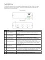
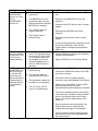
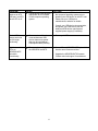
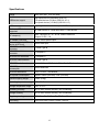
Series USB 2.0
Fiber Optic Extender
User Guide
02/20/12JPK
Thank you for purchasing the American Fibertek
USB 2.0 Fiber Optic Extender
Please read this guide thoroughly.
This document applies to Part Numbers:
MTX-USB2.0 Module, MRX/RRX-USB2.0 Module, RRX-USB2.0 Rackcard
FCC Radio Frequency Interference Statement Warning
This device complies with Part 15 of the FCC Rules. Operation is subject to the following two conditions: (1)
this device may not cause harmful interference, and (2) this device must accept any interference received
including interference that may cause undesired operation.
CE Statement
We declare under our sole responsibility that the Product Name, conforms to the European Standard EMC
EN-55022:2006+A1:2007 Class B, EN 61000-3-2:2006, EN 61000-3-3:2003, and EN 55024:1998+A2:2003.
IC Statement
This Class B digital apparatus complies with Canadian ICES-003.
Contents
Introduction................................................................................................................................................... 4
Product Name Product Contents ................................................................................................................ 4
Requirements.............................................................................................................................................. 4
About the Product Name............................................................................................................................. 4
The MRX/RRX Unit .................................................................................................................................... 5
The MTX Unit .............................................................................................................................................. 6
Installation Guide.......................................................................................................................................... 7
Installing the MRX/RRX Unit ....................................................................................................................... 7
Installing the MTX Unit ................................................................................................................................ 7
Connecting the Local Unit to the Remote Unit ............................................................................................ 8
Checking the Installation ............................................................................................................................. 8
Connecting a USB Device........................................................................................................................... 9
Troubleshooting ........................................................................................................................................... 9
Specifications ............................................................................................................................................. 12
Limited Hardware Warranty ....................................................................................................................... 13
Hardware Remedies ................................................................................................................................... 13
Limitation of Liability.................................................................................................................................. 13
Obtaining Warranty Service....................................................................................................................... 14
Contacting Technical Support................................................................................................................... 14
Technical Glossary..................................................................................................................................... 15
Introduction
The instructions in this guide assume a general knowledge of computer installation procedures,
familiarity with cabling requirements, and some understanding of USB devices.
Series USB 2.0 Fiber Optic Extender Product Contents
Your Product Name is packaged with:
MRX or RRX unit (Local Extender)
MTX unit (Remote Extender)
AC power adapter (for each module)
User Guide
Requirements
To complete the installation, you will also require the following items that are not included with the
product:
USB 1.1 or 2.0 compatible computer (host computer) with a USB compliant operating system
USB 1.1 or 2.0 compatible device
Two 2-strand fiber optic patch cords with Duplex LC connectors (if using premise cabling)
About the AFI Series USB 2.0 Fiber Optic Extender
The AFI Series USB 2.0 Fiber Optic Extender incorporates patented ExtremeUSB® technology, enabling
users to extend beyond the standard 5m cable limit for USB peripheral devices. With the AFI Series USB
2.0 Fiber Optic Extender, USB devices can be located up to 10 kilometers from the computer.
The AFI Series USB 2.0 Fiber Optic Extender is composed of two individual units; the MRX/RRX unit and
the MTX unit.
4
The MRX/RRX Unit
The MRX/RRX unit connects to the computer/host using a standard USB cable. Power for this unit is
provided by the USB on the host computer. The MRX/RRX may be powered from either the USB
computer/host or from external power .
Front View MRX
Rear View MRX
ITEM TYPE
DESCRIPTION
1
Power LED (Blue)
LED turns on when power is supplied. Off when no power is
supplied.
2
Link LED (Green)
Indicates a valid ExtremeUSB® link is established between the
MRX/RRX and MTX.
3
Host LED (Green)
Indicates that the AFI Series USB 2.0 system is properly
enumerated on the host PC. LED blinks when in suspend state.
4
Activity LED (Amber)
Indicates activity when data transmission is active between
MRX/RRX and MTX. LED blinks intermittently with or without a USB
device connected. When the MRX/RRX and MTX are in suspend
mode, the LED is off.
5
Earth Ground
Optional earth ground connection to housing of unit. Accepts an M2
type screw.
6
Power Port (optional)
Not required in normal operation. An optional 5V power supply can
be connected to the MRX/RRX unit to provide power if the USB port
on the host PC is not capable of delivering 500mA to the unit.
7
USB Type B connector
Used to connect the MRX/RRX unit to the host computer.
8
Link Port (Duplex LC)
Extension link Duplex LC fiber optic transceiver port.
5
The MTX Unit
The MTX unit provides USB Type A ports for standard USB devices. The MTX unit allows you to connect
up to four USB devices directly. Additional devices may be connected by attaching USB hubs to the MTX
unit. The MTX unit is powered by an external AC adapter and can supply up to 500mA to each USB port.
Front View
Rear View
ITEM TYPE
1
DESCRIPTION
Device Port (USB Type A)
USB device connection.
2
Device LED
(Green/Amber)
Indicates when a USB device is connected to the Device Port. Solid
green when device is plugged in and active. Off when device is in
suspend mode or MTX unit is powered off. Amber when the MTX unit
detects an overcurrent status and the attached USB device attempts to
draw more than the 500mA current.
3
Power LED (Blue)
LED turns on when power is supplied. Off when no power is supplied.
4
Link LED (Green)
Indicates a valid ExtremeUSB® link is established between the
MRX/RRX and MTX.
5
Host LED (Green)
Indicates that the AFI USB 2.0 system is properly enumerated on the
host PC. LED blinks when in suspend mode.
6
Activity LED (Amber)
Indicates activity when data transmission is active between MRX/RRX
and MTX. LED blinks intermittently with or without a USB device
connected. When the MRX/RRX and MTX are in suspend mode, the
LED is off.
7
Earth Ground
Optional Earth Ground connection to housing of unit. Accepts an M2
type screw.
8
Power Port
Connects to the AC power supply. Required on MTX for proper
operation.
9
Link Port (Duplex LC)
Extension link Duplex LC fiber optic transceiver port.
6
Installation Guide
USB extension up to 10 km over singlemode / 1 km multimode fiber optic cable
Fiber Optic Link Cabling
The MRX/RRX and MTX units are interconnected by up to 10 kilometers (single mode), 1km (multimode)
of fiber optic cabling. Two fibers are required to support the long reach connection. The cabling
subsystem must provide a duplex connection with crossover, and must be terminated with Duplex LC
connectors at both ends.
Installing the AFI USB 2.0 Fiber Optic Extender System
Before you can install the AFI USB 2.0 Fiber Optic Extender, you need to prepare your site:
1.
2.
Determine where the computer is to be located and set up the computer.
Determine where you want to locate the USB device(s).
Installing the MRX/RRX unit
1.
2.
Place the MRX/RRX unit near the computer.
Install the supplied USB cable between the MRX/RRX and USB port on the host computer.
Installing the MTX unit
1.
2.
3.
Place the MTX unit near the USB device(s).
Plug the power adapter into a suitable AC outlet.
Connect the power adapter to the MTX unit.
7
Connecting the MRX/RRX Unit to the MTX Unit
The MRX/RRX and MTX units are interconnected by up to 10 kilometers (single mode), 1km (multimode)
of fiber optic cabling. Two fibers are required to support the long reach connection. The cabling
subsystem must provide a duplex connection with crossover, and must be terminated with Duplex LC
connectors at both ends.
Checking the Installation
1. On the MRX/RRX and MTX units, check that the Power, Host, and Link LEDs are on and that the
Activity LED is blinking. If the Link LED is permanently off, then the cabling between the
MRX/RRX and MTX unit is not installed properly or is defective.
2. For Windows users (2000, XP, Vista, Windows 7), open Device Manager to confirm that the AFI
Series USB 2.0 has installed correctly. Expand the entry for Universal Serial Bus controllers by
clicking the + sign. If the Product Name has been installed correctly, you should find it listed as a
Generic USB Hub .
3. For Mac OS X users, open the System Profiler to confirm that the AFI Series USB 2.0 has installed
correctly. In the left hand column under Hardware, select USB and inspect the right hand panel. If
the Product Name has been installed correctly, you should find it listed as a Hub under the USB
High-Speed Bus/USB Bus.
4. If the AFI Series USB 2.0 is not detected correctly or fails to detect, please consult the
Troubleshooting section.
To open System Profiler in OS X: Open the Finder, select Applications, then open the Utilities folder and
double click on the System Profiler icon.
To open Device Manager in Windows 2000 or XP:
Right click My Computer then select: Properties >> Hardware tab >> Device Manager
To open Device Manager in Windows Vista or Windows 7:
Open the Start menu, right click on Computer then select: Manage >> Device Manager
8
Connecting a USB Device
1. Install any software required to operate the USB device(s). Refer to the documentation for the
USB device(s), as required.
2. Connect the USB device to the device port on the MTX unit.
3. Check that the device is detected and installed properly in the operating system.
Compatibility
The AFI Series USB 2.0 complies with USB 1.1 and USB 2.0 specifications governing the design of USB
devices. However, American Fibertek does not guarantee that all USB devices are compatible with the
AFI Series USB 2.0, as there are a number of different configurations that may impact the operation of
USB devices over extended distances.
Troubleshooting
The following table provides troubleshooting tips. The topics are arranged in the order in which they
should be executed in most situations. If you are unable to resolve the problem after following these
instructions, please contact technical support for further assistance.
PROBLEM
All LEDs on
MRX/RRX unit are
off.
All LEDs on MTX
unit are off.
CAUSE
The MRX/RRX unit is not
receiving enough power from
the USB port or the
(optional) MRX/RRX AC
adapter.
The MTX unit is not
receiving power from the AC
adapter.
SOLUTION
1. Ensure the USB connection between the
MRX/RRX and host computer is properly
installed.
2. Move the USB connector to another USB
port on the host computer.
1. Ensure that the AC power adapter is
properly connected to the MTX unit.
2. Check that the AC adapter is connected to
a live source of electrical power. Check that
the MTX power LED is illuminated.
Link LEDs on
MRX/RRX unit and
MTX unit are off.
There is no connection
between the MRX/RRX and
MTX unit.
1. Ensure that a singlemode fiber optic cable
with crossover is connected between the
MRX/RRX and MTX units.
2. Connect a short fiber optic crossover patch
cord between the MRX/RRX and MTX
units. Recheck operation of the system.
9
PROBLEM
Link LED on
MRX/RRX/MTX
units are on, Host
LED on
MRX/RRX/MTX
units are off.
CAUSE
The host computer is not
powered on.
SOLUTION
1. Disconnect all USB devices from the MTX
unit.
The MRX/RRX unit is not
connected to the computer
(when used with the optional
MRX/RRX AC adapter).
The computer does not
support USB hubs.
All LEDs on both
the MRX/RRX unit
and MTX unit are
on, but the USB
device does not
operate correctly or
is detected as an
Unknown Device
in the operating
system.
3. Disconnect the MTX unit from the AC power
adapter.
4. Reconnect the MRX/RRX unit to the
computer.
The Product Name is
malfunctioning.
AFI Series USB 2.0
units were working
but the HOST LED
on MTX unit is
suddenly blinking.
2. Disconnect the MRX/RRX unit from the
computer.
5. Reconnect the MTX unit to the AC power
adapter.
The MTX unit is in suspend
mode. The operating system
may put the AFI Series USB
2.0 in suspend mode when
the computer is put into a
Suspend/Standby state or
when no USB devices are
attached.
The USB device is
malfunctioning.
The computer does not
recognize the USB device.
The application software for
the device is not operating.
6. In the Universal Serial Bus controllers section
of the Device Manager, check that the
Product Name is recognized as a Generic
USB Hub .
1. Recover/Resume the operating system from
Suspend/Standby mode (see your operating
system s documentation).
2. Attach a USB device to the Product Name.
1. Disconnect the MRX/RRX from the computer.
2. Connect the USB device directly to the USB
port on the computer.
3. If the device does not operate properly,
consult the user documentation for the device.
4. Update your system BIOS, chipset or USB
Host controller drivers from your
System/Mother board manufacturer s website.
The AFI Series USB 2.0
system is malfunctioning.
5. If the device operates properly when directly
connected to the computer, connect another
device (of a different type) to the Product
Name. Connect the Product Name to the
computer.
6. If the second device does not operate, the
Product Name may be malfunctioning.
Contact technical support for assistance.
7. If the second device does operate properly,
the first device may not be compatible with
the Product Name.
10
PROBLEM
USB device is
attached to MTX
USB port, but MTX
device LED is off.
CAUSE
A USB device must have the
appropriate driver installed
on the computer operating
system.
SOLUTION
1. Install the required USB device driver on
the computer operating system prior to
attaching the USB device to the MTX unit.
Please see your USB device
manufacturer s website for details.
2. Consult your USB device documentation,
and power your USB device with the
additional USB device manufacturer
supplied power supply (if available).
Device LED is
orange and units
are no longer
functioning.
Overcurrent condition has
occurred because USB
device draws more power
than can be supplied per
USB specification (500mA).
1. Power cycle MTX.
Link Host and Link
LEDs on
MRX/RRX/MTX
units blink
intermittently.
Firmware mismatch between
the MRX/RRX and MTX.
1. Use a different MRX/RRX/MTX pair which
has the same firmware revision.
2. Upgrade the MRX/RRX/MTX firmware.
Contact technical support for assistance.
11
Specifications
Range
10km over SMF, 1km over MMF
USB device support
High-speed devices (480 Mb/s) (USB 2.0)
Full speed devices (12 Mb/s) (USB 2.0 & 1.1)
Low-speed devices (1.5 Mb/s) (USB 2.0 & 1.1)
USB hub support
Any single chain can include up to 3 USB hubs plus one Product Name.
Maximum USB devices
supported
14 USB Devices or 3 USB hubs with 11 USB devices.
AC adapter(s)
Input: 100/240V AC, 50 - 60 Hz, 600mA maximum
Output: 5V DC, 3 A
AC adapter connector
1.7mm centre-positive jack
Power available to USB
device at MTX unit
MRX/RRX unit USB
connector
MRX/RRX unit Link
connector
500mA each port
1 x USB Type B
1 x Duplex LC
MTX unit Link connector
1 x Duplex LC
MTX unit USB connector
4 x USB Type A
MRX/RRX unit dimensions
3.94 X 2.99 x 1.02 Module, 6½ x 5 x 1 Rackcard
MRX/RRX power
consumption
500mA Maximum
MTX unit dimensions
3.94 X 2.99 x 1.02 Module
MTX power consumption
Approx. 500mA (No load). 2.5A (Full load)
System shipping weight
2.0lbs. (0.9kg)
Operating temperature range
0 C to 60 C
Storage temperature range
-20 C to 70 C
Operating humidity
20% to 80% relative humidity, non-condensing
Storage humidity
10% to 90% relative humidity, non-condensing
Regulatory testing
FCC (Class B), IC (Class B), CE (Class B)
ESD rating
EMC EN-61000-4-2 8kV Contact, 16kV Air
12
LIFETIME WARRANTY INFORMATION
American Fibertek, Inc warrants that at the time of delivery the products delivered will be free of defects
in materials and workmanship. Defective products will be repaired or replaced at the exclusive option of
American Fibertek. A Return Material Authorization (RMA) number is required to send the products back
in case of return. All returns must be shipped prepaid. This warranty is void if the products have been
tampered with. This warranty shall be construed in accordance with New Jersey law and the courts of
New Jersey shall have exclusive jurisdiction over this contract. EXCEPT FOR THE FOREGOING
WARRANTY, THERE IS NO WARRANTY OF MERCHANTABILITY OR FITNESS FOR A
PARTICULAR PURPOSE OR OTHERWISE, EXPRESSED OR IMPLIED, WHICH EXTENDS BEYOND
THE WARRANTY SET FORTH IN THIS AGREEMENT. In any event, American Fibertek will not be
responsible or liable for contingent, consequential, or incidental damages. No agreement or
understanding, expressed or implied, except as set forth in this warranty, will be binding upon American
Fibertek unless in writing, signed by a duly authorized officer of American Fibertek.
To help us serve you better, please include the following information with your technical support request:
Host computer make and model,
Type of operating system installed (e.g. Windows XP, Mac OS X, Windows 7 etc.),
Part number and serial number of both MRX/RRX unit and MTX unit,
Make and model of any USB device(s) attached to the Product Name,
Description of the installation,
Description of the problem.
13
Technical Glossary
USB Cables
USB cables have two distinct connectors. The Type A connector is used to connect the cable from a
USB device to the Type A port on a computer or hub. The Type B connector is used to attach the USB
cable to a USB device.
Duplex LC
When a crossover fiber optic cable is called for, the cable has the transmit signal on one end connected
to the receive signal at the other end.
TX
RX
14