1
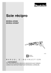
Recipro
Saw
MODEL
JR3030
Variable
MODEL
Speed
JR3030T
Variable Speed
INSTRUCTION MANUAL
[_
DOUgLE
INSULATION
SPECIFICATIONS
Model
Length of stroke
Strokes per minute
28 mm (1-3/32")
I
* Manufacturer
WARNING:
SAVE
reserves
Specifications
For your
THESE
the
right to change
may differ
personal
INSTRUCTIONS
Overall length
0 -- 2,600
JR3030
JR3030T
Note:
__
from
safety,
FOR
specifications
country
READ
FUTURE
and
438
mm (17-1/4"1
460 mm
(18-118")
without
notic_
to country.
UNDERSTAND
REFERENCE.
before
using.
l
3.5 Net
kg weight
17,7 Ibs)
GENERAL SAFETY RULES
(For All Tools)
WARNING!
Read and understand all instructions.
Failure
to follow all instructions listed below, may result in electric
shock, fire and/or serious personal injury.
SAVE THESE INSTRUCTIONS
READ ALL INSTRUCTIONS.
WORK AREA
1. Keep your work area clean and well lit. Cluttered benches and dark areas invite
accidents.
2, Do not operate power tools in explosive atmospheres, such as in the presence
of flammable liquids, gases, or dust. Power tools create sparks which may
ignite the dust or fumes.
3. Keep bystanders, children, and visitors away while operating
Distractions can cause you to lose control.
a power tool.
ELECTRICAL SAFETY
4. Double Insulated tools are equipped with a polarized plug (one blade is wider
than the other.) This plug will fit in a polarized outlet only one way. If the
plug does not fit fully in the outlet, reverse the plug. If it still does not fit,
contact a qualified
electrician to install a polarized outlet. Do not change
the plug in any way. Double insulation [] eliminates the need for the three
wire grounded power cord and grounded power supply system.
5. Avoid body contact with grounded surfaces such as pipes, radiators, ranges
and refrigerators.
There is an increased risk of electric shock if your body is
grounded.
6. Don't expose power tools to rain or wet conditions.
tool will increase the risk of electric shock.
Water entering
a power
7. Do not abuse the cord. Never use the cord to carry the tools or pull the plug
from an outlet. Keep cord away from heat, oil, sharp edges or moving parts.
Replace damaged cords immediately.
Damaged cords increase the risk of
electric shock.
8. When operating a power tool outside, use an outdoor extension cord marked
"W-A'" or "W." These cords are rated for outdoor use and reduce the risk
of electric shock,
PERSONAL SAFETY
9. Stay alert, watch what you are doing and use common sense when operating
a power tool. Do not use tool while tired or under the influence of drugs,
alcohol, or medication.
A moment of inattention while operating power tools
may result in serious personal injury.
10. Dress properly. Do not wear loose clothing or jewelry. Contain long hair. Keep
your hair, clothing, and gloves away from moving parts. Loose clothes, jewelry
or long hair can be caught in moving parts.
2
11. Avoid accidental starting. Be sure switch is off before plugging in. Carrying
tools with your finger on the switch or plugging in tools that have the switch
on invites accidents.
12. Remove adjusting keys or switches before turning the tool on. A wrench or
a key that is left attached to a rotating part of the tool may result in personal
injury.
13. Do not overreach. Keep proper footing and balance at all times. Proper footing
and balance enables better control of the tool in unexpected situations.
14. Use safety equipment.
Always wear eye protection.
Dust mask, non-skid
safety shoes, hard hat, or hearing protection must be used for appropriate
conditions.
TOOL USE AND CARE
15. Use clamps or other practical way to secure and support the workpiece to
a stable platform. Holding the work by hand or against your body is unstable
and may lead to loss of control.
16. Do not force tool. Use the correct tool for your application, The correct tool
will do the job better and safer at the rate for which it is designed.
1"/. Do not use tool if switch does not turn it on or off. Any tool that cannot
be controlled with the switch is dangerous and must be repaired.
18. Disconnect the plug from the power source before making any adjustments,
changing accessories, or storing the tool. Such preventive safety measures
reduce the risk of starting the tool accidentally.
lg.
Store idle tools out of reach of children and other untrained
are dangerous in the hands of untrained users.
persons. Tools
20. Maintain tools with care. Keep cutting tools sharp and clean. Properly
maintained tools, with sharp cutting edges are less likely to bind and are easier
to control.
21. Check for misalignmsnt
or binding of moving parts, breakage of parts, and
any other condition that may affect the tools operation. If damaged, have
the tool serviced before using. Many accidents are caused by poorly maintained tools.
22. Use only accessories that are recommended
by the manufacturer
for your
model. Accessories that may be suitable for one tool, may become hazardous
when used on another tool.
SERVICE
23. Tool service must be performed only by qualified repair personnel. Service
or maintenance
performed by unqualified personnel could result in a risk of
injury.
24. When servicing a tool, use only identical replacement parts. Follow instructions in the Maintenance
section of this manual. Use of unauthorized parts
or failure to follow Maintenance Instructions may create a risk of electric shock
or injury.
Specific
Safety
Rules
1. Hold tool by insulated gdpping surfaces when performing an operation where
the cutting tool may contact hidden wiring or its own cord. Contact with
a "live" wire will also make exposed metal parts of the tool "live" and shock
the operator.
2. Avoid cutting
operation.
nails. Inspect workplace
3. Do not cut oversize
for any nails and remove them before
workpiece.
4. Check for the proper clearance beyond the workpiece
the blade will not strike the floor, workbench,
etc.
before cutting
so that
5, Hold the tool firmly.
6, Make sure the blade is not contacting
turned on.
7. Keep hands away
from moving
8. Do not leave the tool running.
the workplace
before the switch
parts.
Operate
the tool only when
hand-held.
9. Always switch off and wait for the blade to come to a complete
removing the blade from the workpiece,
10. Do not touch the blade or the workpiece immediately
may be extremely hot and could burn your skin,
SAVE THESE INSTRUCTIONS.
4
is
stop before
after operation;
they
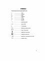
SYMBOLS
The followings show the symbols used for tool.
V
.................................
volts
A
.................................
amperes
Hz
.................................
herts
kg
h
.................................
.................................
kilograms
hours
rain
.................................
minutes
S
.................................
seconds
.................................
alternating current
....
.................................
direct current
n,
.................................
no load speed
.................................
alternating or direct current
.................................
Class II Construction
L_
.................................
splash-proof construction
_l _
.................................
watertight
..Jmin
................................ revolutions or reciprocation per minute
[_
.................................
construction
number of blow
FUNCTIONAL
DESCRIPTION
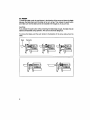
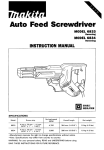
Ad]. ng =11oo
When the blade loses its cutting efficiency
in one place along its cutting edge, reposition the shoe to unitize a shaqo, unused
portion of its cutting edge. This will help to
lengthen the life of the blade. To reposition
the shoe, loosen the lever and slide the
shoe forward or back to the desired position. Then tighten the lever to firmly secure
the shoe.
Loos_tt
Shoe
Switch action
CAUTION:
Beforepluggingin the tool, alwayscheckto see that the switch triggeractuatesproperly
and returnsto the "OFF" position when released.
To start the tool, simply pull the trigger.
Tool speed is increased by increasing pressure on the trigger. Release the trigger to
stop. For continuous operation, pull the trigger and then push in the lock button. To
stop the tool from locked position, pull the
trigger fully, then release it.
Lockbutton
Switch trigger
i
ASSEMBLY
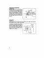
Installing or removing the saw blade
CAUTION:
• Always be sure that the tool is switched off and unplugged before installing or removing
the blade.
oAIways clean out all chips or foreign matter adhering to the blade, blade clamp and/or
slider. Failure to do so may cause insufficient tightening of the blade, resulting in a serious injury.
For JR3030
To install the blade, loosen the screw on
the blade clamp with the hex wrench 4 provided. Insert the blade between the blade
clamp and the slider so that the pin on the
slider fits into the hole in the blade shank. If
the pin cannot easily fit into the hole,
remove the hex wrench from the screw
and then try again. After the pin fits properly into the hole, tighten the screw securely
while making sure that the blade cannot be
extracted even though you try to pull it out.
CAUTION:
If you tighten the screw without the pin on
the slider fitting properly in the hole in the
blade shank, the pin or the blade shank wig
be damaged. This may cause the blade to
be ejected unexpectedly during operation.
This can be extremely dangerous.
Blade
H_S
To install the blade, loosen the screw on the blade clamp with the hex wrench 4.
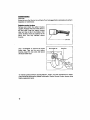
For JR30301"
To installthe blade,pushthe pushbutton in the directionof the arrowand insertthe blade
between the bladeclamp and the slider as far as it will go. Then release the pushbutton
and make sure that the bladecannotbe extractedeven thoughyou try to pull it out.
CAUTION:
If you releasethe pushbuttonwithout insertingthe bladedeep enough,the blademay be
ejected unexpectedlyduringoperation.Thiscan be extremely dangerous.
To remove the blade, push the push button in the direction of the arrow and pull out the
blade.
Bade
$
Push button
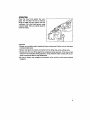
OPERATION
Press the shoe firmly against the workpiece. Do not allow the tool to bounce.
Bringthe blade into light contact with the
workpiece. First,make a pilotgroove, using
a slower speed.Then use a faster speed to
continuecutting.
CAUTION:
• Always use a suitable coolant (cutting oil) when cutting metal. Failure to do so wil{ cause
premature blade wear.
• Always wear gloves to protect your hands from hot flying chips when cutting metal.
• Always press the shoe firmly against the workpiece during operation. If the shoe is held
away from the workpiece during operation, strong vibration and/of twisting will be produoed, causing the blade to snap dangerously.
• Be sure to always wear suitable eye protection which conforms with current national
standard_
MAINTENANCE
CAUTION:
Always be sure that the tool is switchedoff and unpluggedbefore attemptingto perform
inspection or maintenance.
Replacing carbon brushes
Remove and check the carbon brushes
regularly. Replace when they wear down to
the limit mark. Keep the carbon brushes
clean and free to slip in the holders. Both
carbon brushes should be replaced at the
same time. Use only identical carbon
brushes.
Urnit mark
Use a screwdriver to remove the brush
holder caps. Take out the worn carbon
brushes, insert the new ones and secure
the brushholdercaps.
Brush holder cap
Screwdriver
To maintain product SAFETY and RELIABILITY, repairs, any other maintenance or adjustment should be performed by Makita Authorized or Facto_ Service Centers, always using
Makita replacement parts.
10
ACCESSORIES
CAUTION:
These accessories or attachments are recommended
for use with your Makita tool specified in this
manual The use of any other accessoriesor attachmentsmight present a riskof injuryto persons.
These accessories
or attachments
should be used only in the proper and intended manner,
NOTE: The accessories listed in this manual are available at the extra cost from your Makita distributor or Makita Factory Service Center. Service Centers are listed on the warranty card packed with
your tool.
Saw Blad_
Wood
Cutting
Qty
I_r Pkg
Teeth
Per inch
O,*wa0
Length
723018-A_5
5
6
6"
723018-A-2
2
S
6"
High Carbon Steel
Ream Ground
(0.049")
Cuts hall free wood
rough in work.
723018-B-5
723018-B-1
5
1
6
6
12"
12"
High Carbon Steel
Fleam Ground
{0.049")
Cuts nail free wood
-- rough in work.
5
6
6"
High Alloy Steel
Milled (0.031 ")
Cuts composition
materials
- resists
Pwt
Bladls
#
72301S-C-5
•
Tooth
Specifi.ttom
Apldi.tion
nall damage.
723018-D-5
723018-D-2
5
2
10
10
723018-E-5
723018-P-5
Metal
Cutting
For rapid cutting
Blades
_J_
High Alloy Steel
Milled (0.031 ")
6"
H_h Carbon Steel
Ream Ground
(0.049")
6"
High Atloy Steet
M/V Alternate
[0.041 "')
Cutsplaster,
metal
lath, plasterboard,
Cuts circles and
contours
in nail free
wood,
compo|dionl.
723019_-5
723019-G-2
5
2
14
14
4""
4"
High Speed Steel
Mitled/Raker
Set
(0.031'*)
For cutting metal
over 1/8" thick,
723019-A-5
723019-A-2
S
2
14
14
6"
6"
High Speed Steel
Milled/Raker
Se_
(0.031 "(
For cutting
metal
over 1/8" thick.
723019-B-5
5
18
4"
723019-B-2
2
18
4"
High Speed Steel
Milisd/Raker
Set
(0.031 '*)
For cutting
over 3164"
723019-H-5
a
18
4"
High S_ed Steel
Milled/Wavy
(0.049") Set
For scroll cuts in
metal 3/64" thick
and over.
723019_-5
723019_-2
5
2
18
18
6"
6"
High Speed Steel
Milled/Re
ker Set
(0.031")
For cutting metal
over 3/64" thick.
723019-K-5
723019-K-2
a
2
24
24
44"
High SOeed Steel
Milled/Waw
Set
(0.031 ")
For cutting metal
less than 3/64" thick.
723019-D-5
723019-D-2
24
24
6"
6"
High SPeed Steel
Milled/Wavy
Set
(0,031 ")
For cutting
metal
less than 3/64"
thick.
723019J-5
36
4"
High Soeed Steel
Milled/Wavy
Set
(0.031 ")
For cutting metal
less than 1/32" thick.
of
metal Bnd fiberglass,
Made of high speed
steel.
,
Cuts coml;)Osdion
I_
plywood
-- resist_
nell damage.
6"
6"
•
%
Note;
All illustrations
shown are general representations
Actual design of blades may vary slightly.
for blades
metal
thick.
in that category.
11
ACCESSORIES
Saw Ehdm
Combination
of high
spud stui tleth
welded to a shatter.
flexible
blade.
blade,
Ultra-long
Oty
PwPkg
Part#
Bi-metM Blades
proof,
continuedOwlrllll
Llmgth :
Tooth
SIHclflcltiOml
AppliCation
Cuts nail embedded
723017-E-5
723017-E-2
66,*
Bi-metsl
Milled
(0.050")
723017-F-5
12"
B_,metal
milled (0,050")
Cuts nail embedded
wood -- roughing in
work.
Bi-metal
Milled (0.031 ")
CUts nail embedded
wood _ nonferrous
metals.
backed
wood
work.
-
roughing
in
life
723017-A-5
723017-A-2
10
10
6,,
723017-G-5
14
d,,
Bi-metjl
Milled {0.03_
Cuts metal
and over,
1/8"
thick
")
723017-B-5
723017-B-2
t4
14
6"
6"
Bi-rnetal
Milled (0.031
Cuts metal
and over.
1/8"
thick
")
723017-H-5
723017-H-2
18
18
4"
4"
ai-metal
Milled (0.031 ")
Cuts metal 3/64"
thick and over.
10
18
6"
6"
Bi-matal
Milled (0.031 ")
Cuts metal 3/64"
thick and o_r,
ai-mat81
Milled (0.031")
Scroll cuts in metals
_r
3164" thick, fiberglm. compositions.
723017_'_"
723017-C-2
5
B,,
723017-K-5
18
723017J-5
7230174-2
24
24
4"
4"
Bi-metal
Milled (0.031
"|
Cuts metal less than
3/64" thick.
723017-D-5
723017-D-2
24
24
6"
6"
Bi-metal
Milled (0.031 ")
Cuts metal lesslhan
3/64" thick.
3 Piece Variety Pack
Wood and Metal Cutting
includes 1 each: 723018-A
723018-D
723019-C
This packisavailableunder
PartNo, 723016-3-A
• PIl_tic "rootc_=m
Accommodated tool with 6" blade.
12
Teeth
Perll_h
3-1/2"
3 Piece Variety Pack
Ultra Long Life Bi-metal
includes 1 each: 723017-E
723017-B
723017-C
This packis availableunder
PartNo. 723016-3-B
• He]( Wrench 4 (For Model Jl_030)
Part No. 783202-0
Feb--18
,99
US
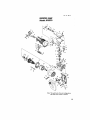
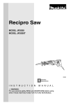
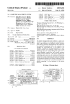
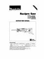
RECIPRO SAW
Model JR3030
65
68_
70
Note: The switch and other part configurations
may differ from country to country.
13
Feb.-18-'99
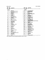
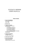
MODEL JR3030
ITEM
NO.
NO_
USED
ITEM
N_
DESCRIPTION
1
2
3
2
I
I
I
!
2
I
2
I
made C4amp
Hex.
Socket
Screw
Head BO_ M5x15
MSxl0
Twppin9 Scxew
Felt Retorter
5
6
?
8
9
10
11
12
13
14
lS
16
17
18
19
2O
21
22
23
14
25
28
27
28
29
Bind CT 5xl2
Fell Ring 14
Fta_ Wuhe_
14
X R_ng 14
Flal Wesher
Gear
16
Housing
Cover
Pan Head Screw
_0
MSx30
Shoe F_Btt
Stop Rirtg EFlex.
52
_3
_4
S6
_6
57
58
59
_0
3
Lock Nut MS-8
Pm4
He_.
Sock_
S_ing
Bore MSx45
Washer
S
Shoe Sups)or tes
Irmuletlofl
Sleeve
Cov_r
9
Inner Pl8te
Pan Head
Scrww
M4xlO
52
83
54
65
56
67
68
69
70
71
72
73
74
75
76
77
78
Lock Plate
Hex.
Bo_t MSx25
Lever
Hex,
60
Nut M4
Packing
4,
,
P_a_
12_16
Piene Bearing
t4
Plate
31
32
33
Pan He_
Slide
Screw
MSx16
Plate
Slider
Needle
Bering
Hex. Socket
35
36
37
38
39
708
Head Bolt MtOx_8
Gee;' Complete
Prate 12x16
Plane 8ee¢ing
14
Plef:e
The
DESCRIPTION
MACHINE
MACHINE
Note:
NO.
USED
switch
and
other
par_ specifications
m_Y
differ
from country
to country.
• n Head Screw MSx16
Bear;n9 Botain_ 56
BaNBear_O 6202LLB
RmglS
Ball Bearing 6902
Hex. Socket _
Bolt MSx12
Plate ICI
Tapping Screw 5x30
Gear Hot_n 0
Be_k_g RetBiner
p_ HUrl Screw MSx8
T_IOG Screw 5x4S
Gear Shah
Pan Head Screw MSx8
RItRioing Rin0 S- 12
Bsll 8e_ing 60OIDOW
ARMATURE ASS_M_L.Y (W_th It_
Emff1_Pixie
T_ng
Screw SX60
Ro_ine_
FIELD ASS£MBLY
Insumted Washer
B_ar_n0 608Dew
Nm
Pl_e
Motor Houling Complete
C_t)on B_ush
Brush Holder Cap
"r_g
Screw 4x20
Hend_eSet (Wi'_h Item 70)
Switch Lover
H_mdleSet _V_h Itlm 68)
Compression S_mg 4
t_c_.k-O1_Sutton
Swath
T_qop*ngScrew 4x18
Siren Relief
CO_I Gu_d
Cord
compression Spnns 5
(_I & 621
US
MAKITA LIMrI ) ONE YEAR WARRANTY
Warranty Policy
Ev©ry Makilatoolb thoroughly
"ms_scted
and t_ted beforele_
thefactow. Iti_w_mt ed to
be fxceof defectsfTom workmlp
L_dmaterials
forthepe,
r_odofONE YEAR fromthedateof
o_Inal _Me.
_ould an},trouble,
d_elop dad_ th=_m_-y_ pe_od,_tusn.t_eO_MPLETE
cool fn_t
pn_p.id, to one of Mskita s FL-_P/or Autho"_. Se_e _tcrL Ifmsp_tion shpws
the trouble b csmed by dcfcc_e wodmumship or matcr_l, Makiu win _*_it (or at our optton,
repine) without cktrl_.
This Warranty do_ not apply whez_:
• zq_sJxs
have bee_ made or attempted by others :
• r_,pairszrz requim_dbocsus_ of _ormad wezr and tcax:
• The tool hasbeen zbused, misusedor improperly maintained;
• attexatiom have been madeto th© tool.
IN NO EVENT SHALL MAKITA BE LIABLE FOR ANY INDIRECT, INCIDENTAL OR CONSEQUENTIAL DAMAGES FROM THE SALE OR USE OF THE PRODUCT. THIS DISCLAIMER
APPLIES BOTH DURING AND AFTER THE TERM OF THIS WARRANTY.
MAKITA DISCLAIMS LIABILITY FOR ANY IMPLIED WARRANTIES. INCLUDING IMPLIED
WARRANTIES OF "MERCHANTABILITY"
AND "FITNESS FOR A SPECIFIC PURPOSE."
AFTER THE ONE-Y EAR TERM OF THIS WARRANTY.
This Warnmty IiVn you sped_
l©pl r_ts. and you may also have other rights whlclt vary from
state m state. Some stat_ do not allow the exclation or ]_mi_tion of incidental or conscque.ntial
dm'aaBes, so the above limitation or exchudon may not apply to you. Som_ stste_ do not allow
limitation on how |ong an imp;i_d warnmty _
so the above lL-altatio, may not apply _ you.
Makita Corporation of America
2650 BufordHwy., Btdord,GA 30518
884230 - 061
PRINTED IN USA