1
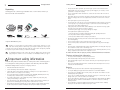
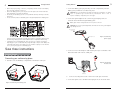
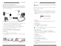
MAX™ Wireless
Installation & Operation Manual
ii
Table of Contents
Introduction
1
Table of Contents
Introduction
Introduction . . . . . . . . . . . . . . . . . . . . . . . . . . . . . . . . . . . . . . . . . . . . . . . . . . . .1
Getting Started . . . . . . . . . . . . . . . . . . . . . . . . . . . . . . . . . . . . . . . . . . . . . . . . .4
Thank you for purchasing the ClearOne MAX™ Wireless conferencing phone. Ideal
for small conference rooms with up to eight participants, MAX Wireless provides the
convenience of wireless without compromising on audio quality or call security.
MAX Wireless is built using the WDCT and DECT wireless standards (depending on
model); standards characterized by reliability, stability, and excellent sound quality.
And with twelve-hour talk-time between recharging, you'll have plenty of time to
experience the difference Max Wireless will make to the way you communicate.
Connecting your conferencing phone . . . . . . . . . . . . . . . . . . . . . . . . . . . . . . . . . . . . . . . . .4
Connecting to a digital phone line . . . . . . . . . . . . . . . . . . . . . . . . . . . . . . . . . . . . . . . . . . .6
Using your MAX Wireless conferencing phone . . . . . . . . . . . . . . . . . . . . . . . . . . . . . . . . . .6
• Wireless. MAX Wireless makes any room a conference room and provides a
clean look with no wires on the table or floor.
User Options . . . . . . . . . . . . . . . . . . . . . . . . . . . . . . . . . . . . . . . . . . . . . . . . . . .8
• Superior Audio. The clear, full sound of MAX Wireless facilitates more
natural interaction among participants.
Service and support . . . . . . . . . . . . . . . . . . . . . . . . . . . . . . . . . . . . . . . . . . . . . . . . . . . . .1
Product returns . . . . . . . . . . . . . . . . . . . . . . . . . . . . . . . . . . . . . . . . . . . . . . . . . . . . . . . . .1
Unpacking . . . . . . . . . . . . . . . . . . . . . . . . . . . . . . . . . . . . . . . . . . . . . . . . . . . . . . . . . . . . .2
Safety . . . . . . . . . . . . . . . . . . . . . . . . . . . . . . . . . . . . . . . . . . . . . . . . . . . . . . . . . . . . . . . .2
Call features . . . . . . . . . . . . . . . . . . . . . . . . . . . . . . . . . . . . . . . . . . . . . . . . . . . . . . . . . . .8
Programming features . . . . . . . . . . . . . . . . . . . . . . . . . . . . . . . . . . . . . . . . . . . . . . . . . . . .9
Tones and alerts . . . . . . . . . . . . . . . . . . . . . . . . . . . . . . . . . . . . . . . . . . . . . . . . . . . . . . . .11
Maintenance . . . . . . . . . . . . . . . . . . . . . . . . . . . . . . . . . . . . . . . . . . . . . . . . . . .12
Caring for your MAX Wireless . . . . . . . . . . . . . . . . . . . . . . . . . . . . . . . . . . . . . . . . . . . . . .12
Electrical considerations . . . . . . . . . . . . . . . . . . . . . . . . . . . . . . . . . . . . . . . . . . . . . . . . . .12
Troubleshooting . . . . . . . . . . . . . . . . . . . . . . . . . . . . . . . . . . . . . . . . . . . . . . . . . . . . . . . . .12
Appendix . . . . . . . . . . . . . . . . . . . . . . . . . . . . . . . . . . . . . . . . . . . . . . . . . . . . . .14
Specifications . . . . . . . . . . . . . . . . . . . . . . . . . . . . . . . . . . . . . . . . . . . . . . . . . . . . . . . . . .14
Compliance . . . . . . . . . . . . . . . . . . . . . . . . . . . . . . . . . . . . . . . . . . . . . . . . . . . . . . . . . . . .15
Warranty . . . . . . . . . . . . . . . . . . . . . . . . . . . . . . . . . . . . . . . . . . . . . . . . . . . . . . . . . . . . . .18
• Easy to Use. The intuitive, user friendly controls are simple to operate.
Service and support
If you need additional information on how to set up or operate your Max Wireless
conferencing phone, please contact us. We welcome and encourage your comments
so we can continue to improve our products and better meet your needs.
Technical Support
Tel:
Fax:
E-mail:
Web:
1-800-283-5936(USA) or 1-801-974-3760
1-801-977-0087
[email protected]
www.clearone.com
Sales and Customer Service
Tel:
1-800-945-7730 (USA) or 1-801-975-7200
Fax:
1-800-933-5107 (USA) or 1-801-977-0087
E-mail: [email protected]
Product returns
MAX Wireless Installation and Operation Manual
ClearOne Part No. 800-158-001 September 2006 (Rev. 3.1)
U.S. Patent No. D499,392.
© 2004 ClearOne Communications, Inc. All rights reserved. No part of this document may be reproduced in any
form or by any means without written permission from ClearOne Communications. ClearOne Communications
reserves specific privileges. Information in this document is subject to change without notice.
All product returns require a return materials authorization (RMA) number. Please
contact ClearOne Technical Support before attempting to return your product. Make
sure you return all the items that shipped with your product.
2
Getting Started
Unpacking
Carefully place the conferencing pod and base unit on a level surface. Ensure you
have received all items shown below.
Se
To
tti
ng
1. ch
up
Sli arg
co
Co de the e
nf
ba
er
pac nne
tte
en
k, ct the cover rie
cin
and
off s
g
slid bat
the
ph
e tery
the pac bat
on
e
cov k ter
er plu y com
bac g
k into partm
int
ent
o the
pla por
ce. t on
the
in
the
bot
com tom
par of
tm the
ent
pod
, ins
.
ert
the
2.
Fig
3.
ure
1.
Co
Con
ele nne
nec
ctr ct
To
ting
ica the
co
1.
and
l out pow
Co nn
cha
let. er
cab nne ect
rgin
Ch sup
of le ct one ba
g
arg ply
se
the
the int
e bat /ch
2. into
o
bat
end un
arg
Co
a bas the
it
ter
ter er
nne wa e uni pho of
y
ies to
3. 2.5
the
ll
for the
Plu mm ct a jac t and ne jac tele
out g
15 con
aud rec k.
the k on pho
let. the
hou fer
io ord
oth the ne
* bas jac ing
rs enc
Th
er
e uni k
pri ing
(if dev
end bac
15 e bas
or
pod
k
t int des ice
0
to
fee e uni
ire to the
*
firs and
o
t fro t
an
d).
A Inte
t use plu
sep rna
ma
ele
m
ara tion
ctr
. g it
the y be
te al
ica
int
pow ver
con loc
l
o
er sion
an
fer ate
ada s
enc d up
pte of
In
ing to
Use
Power
r is the
and
pod
LEDs
incl Ma
ude x Wir
d. eles
s bas
e unit
not
Fig
plu
g
Telephone cord
St
ar
te
d
Gu
id
e
les
s
button
2.
Con
the
Power Cord
ng
W
ire
ure
dire
ctly
into
Base unit
tti
ax
y
Paging
do
Conferencing pod(s)
Ge
M
bat
ter
nec
ting
the
elec
bas
tric
al
e
out
let.
uni
t
Quick start guide
Battery pack(s)
Manual on CD
Power Supply Retainer(s)
Power supply/charger(s)
Figure 1. MAX Wireless parts
ClearOne is not responsible for product damage incurred during shipment. You must
make claims directly with the carrier. Inspect your shipment carefully for obvious signs
of damage. If the shipment appears damaged, retain the original boxes and packing material
for inspection by the carrier. Contact your carrier immediately.
The MAXAttach Wireless model contains two pods, two battery packs, and two power
supply/chargers & retainers. For more information on MAXAttach Wireless, see pg 12.
!
Important safety information
Read the safety instructions before first use of this product.This conferencing phone
is not designed for making emergency telephone calls when the power fails. Make
alternative arrangements for access to emergency services.
• Read and understand all instructions.
• Follow all warnings and instructions marked on the product.
• Unplug this product from the wall outlet before cleaning. Do not use liquid cleaners or
aerosol cleaners. Use a damp cloth for cleaning.
• Do not use this product near water, for example, near a bathtub, washbowl, kitchen sink,
or laundry tub, in a wet basement, or near a swimming pool.
• Do not place this product on an unstable cart, stand, or table. The product may fall,
causing serious damage to the product.
• Slots and openings in the cabinet and the back or bottom are provided for ventilation, to
protect it from overheating, these openings must not be blocked or covered.
• This product should never be placed near or over a radiator or heat register.This product
should not be placed in a built-in installation unless proper ventilation is provided.
Getting Started
3
• This product should be operated only from the type of power source indicated on the
marking label. If you are not sure of the type of power supply in your location, consult
your dealer or local power company.
• Do not overload wall outlets and extension cords as this can result in the risk of fire or
electric shock.
• Never push objects of any kind into this product through cabinet slots as they may touch
dangerous voltage points or short out parts that could result in a risk of fire or electric
shock.
• Never spill liquid of any kind on the product.
• To reduce the risk of electric shock, do not disassemble this product. Opening or removing
covers may expose you to dangerous voltages or other risks. Incorrect reassembly can
cause electric shock during subsequent use.
• Unplug this product from the wall outlet and battery source and refer servicing to qualified service personnel under the following conditions:
a. When the power supply cord or plug is damaged or frayed.
b. If liquid has been spilled into the product.
c. If the product does not operate normally by following the operating instructions.
d. If the product has been dropped or damaged.
e. If the product exhibits a distinct change in performance.
• Avoid using a telephone during an electrical storm. There may be a remote risk of electric
shock from lightning.
• Do not use this product to report a gas leak in the vicinity of the leak.
• Do not use this product near intensive care medical equipment or by persons with pacemakers.
• Due to the radio signals between base station and POD, wearers of hearing aids may experience interference in the form of a humming noise.
• This product can interfere with electrical equipment such as answering machines, TV sets,
radios, computers and microwave ovens if placed too close.
To reduce the risk of fire or injury to persons, read and follow these instructions:
Telephone wiring and jack information
• Use caution when installing or modifying telephone lines.
• Never install telephone wiring during an electrical storm.
• Never install telephone jacks in wet locations unless the jack is specifically designed for
wet locations.
• Never touch uninsulated telephone wires or terminals unless the telephone line is disconnected at the network interface.
Batteries
• Disconnect the product from wall outlet when replacing the battery pack.
• Use only the battery pack type listed in this manual. Do not use lithium batteries.
• Do not dispose of the battery pack in a fire, as they can explode. Check with local codes
for battery disposal regulations.
• Do not open or mutilate the battery pack. Released electrolyte is corrosive and can cause
damage to the eyes or skin. It can be toxic if swallowed.
• Avoid contact with rings, bracelets, keys or other metal objects when handling the battery
pack. These objects could short out the batteries or cause the conductor to overheat,
resulting in burns.
• Do not attempt to recharge the battery pack by heating it. Sudden release of battery
electrolyte can cause burns or irritation to the eyes or skin.
4
Getting Started
• Observe the proper polarity, or direction, of any battery. Reverse insertion of the battery
pack can result in leakage or explosion.
• Remove the battery pack if you do not plan to use the product for several months at a
time. The batteries could leak over that time.
• Discard any “dead” battery pack as soon as possible because they are likely to leak into
the product.
• Do not store this product or the battery pack in a high temperature area. Battery packs
5
Getting Started
2. Connect the battery pack plug into the port in the compartment, insert the
battery pack, and slide the cover back into place.
!
CAUTION: Use only the battery pack that came with this unit. Replace only with a
same or equivalent type recommended by manufacturer. There is risk of
explosion if battery is replaced by an incorrect type.
3. Connect the power adapter to the conferencing pod and plug it into an
electrical outlet. This will charge the battery pack.
Battery packs must be charged at least 15 hours prior to first use.
!
CAUTION: Use only the power adapter that came with this unit. Using other adapters
may damage the unit.
MAX Plus Wireless
Pod Unit
Cable Retainer Unit
stored in a freezer or refrigerator should be protected from condensation during storage
and defrosting. Battery packs should be stabilized at room temperature before using.
• Your battery pack is rechargeable and can be recycled once it outlives its usefulness.
Depending upon your local and state law, it might be illegal to dispose of this battery into
a municipal waste system. Check with your local solid waste company for more information on your recycling options for the battery pack.
Save these instructions
Getting Started
Figure 3. Connecting
power supply
4. Connect one end of the telephone cable into the phone jack on the back of the
base unit and the other end into a wall jack.
Connecting your conferencing phone
1. Slide the cover off the battery compartment on the bottom of the pod.
Figure 4. Connecting
the base unit
In Use and
Power LEDs
Paging button
5.
Connect a recording device to the 2.5mm mono audio jack (if desired).
6. Connect the power cord to the base unit and plug it into an electrical outlet.
Figure 2. Connecting the battery pack
6
Getting Started
Connecting to a digital phone line
WARNING! Do not connect the conferencing phone directly to a digital (PBX) line,
PERMANENT DAMAGE MAY RESULT. If you have digital (PBX) telephone service, you will need a digital-to-analog telephone line converter. For more information,
contact ClearOne technical support.
7
Getting Started
You can also predial the number while in Standby (inactive) mode and press the
ON/OFF key to connect the call. Press and hold the pound key (#) to enter a pause in
the dialing string.
Elapsed time is shown in minutes and seconds until one hour passes.Then elapsed
time is shown in hours and minutes.
To answer a call
• Press any key (except the star “*” key, MUTE, VOLUME UP or VOLUME
DOWN) on the keypad to answer the call. When there is an incoming call, the
phone rings and the LEDs on the phone and the phone icon on the LCD
screen flash.
Phone Jack
Electrical
Outlet
Digital, PBX,
or Multi-line phone
AC Adapter
Phone icon
KONEXX KONFERENCE
Digital-to-Analog
Converter
Figure 7. Incoming call
To end a call
Unit
Figure 5.Base
Connecting
the base unit to digital-to-analog converter
Handset
1. Connect one end of the telephone cable into the phone jack on the back of the
base unit and the other end into the digital-to-analog converter.
2. Connect the converter's power adapter into an electrical outlet.
3. Connect a second telephone cable from the converter to a digital or PBX
phone. Consult the converter user manual for more information.
4. Plug the base unit into an electrical outlet.
Using your MAX Wireless conferencing phone
• Press the ON/OFF key. This will disconnect the call and return the phone to
Standby mode.
To redial a number
1. Press the ON/OFF key. You will hear a dial tone.
2. Press REDIAL to dial the last number called.
You can also press REDIAL while in Standby mode to display the last number called.
To connect the call, press the ON/OFF key.
To adjust ringer volume
• While the phone is ringing, press VOLUME UP or VOLUME DOWN.
To make a call
1. Press the ON/OFF key. You will hear a dial tone.
• While the phone is inactive, press VOLUME UP or VOLUME DOWN. The ringer
melody will play once at the new level.
2. Dial the number as you would on a standard phone. The number is displayed
on the LCD screen.
To mute the call
• Press MUTE to mute the call.
• Press again to unmute.
Phone icon
To make a call using the Phonebook
1. Press the ON/OFF key. You will hear a dial tone.
2. Press PHONEBOOK.
Call timer
Figure 6. LCD screens
Approximate
talk-time remaining
3. Press the number key (0-9) that corresponds with the location of the stored
phone number you want to dial. This feature must be programmed before use.
See page 8.
8
Getting Started
9
User Options
When more than 18 characters are entered, a scroll button will appear on the LCD
display and the numbers will scroll from right to left.
To store a number in the phonebook
1. Enter the phone number you want to store while conferencing pod is in
Standby mode.
To send a Flash signal
2. Press and hold the PHONEBOOK/EDIT key until the Phonebook and Program
icons appear on the LCD screen.
If your telephone service includes call transfer, call waiting, or conference calling,
you can use the Flash key. Refer to your local telephone service for details.
Phonebook and Program icons
To display your local number during a call
• Press CLEAR. The phone number will appear. After several seconds, the call
timer will return.
To adjust loudspeaker volume
Figure 8. Adding Phonebook entries
• Press the VOLUME UP key while on a call to increase volume.
3. Assign a Phonebook location (0–9) by pressing the corresponding number key.
• Press the VOLUME DOWN key while on a call to decrease volume.
4. Press PHONEBOOK again to save the entry. You will hear a confirmation tone.
To turn the ringer on/off
5. To exit Phonebook Edit mode before saving the entry, press CLEAR.
• Press and hold the star (*) key. The Ringer Off icon will illuminate when
ringer is turned off. The icon will not appear when the ringer is on.
Press & hold the “1” key to enter a hyphen or the “*” key to enter a space in the number. Use CLEAR to delete the old number before entering a new number.
Ringer Off
To access your speed dial number
• Press the SPEED DIAL key. This feature must be programmed before use. See
page 10.
Figure 9. Ringer Off icon.
When the ringer is off, LEDs & the
phone icon will flash to indicate
incoming call.
To access your service center
• While in Standby mode, press and hold the 0 key for 2 seconds. This feature
must be programmed before use. See page 10.
To mute during ringing
User Options
Programming features
Call features
In addition to the basic phone operations described in the previous section, you can
perform any of the following functions during a call: change to pulse dialing, send a
flash signal, display phone number, adjust speaker volume, or turn on/off the ringer.
To use pulse dialing
The MAX Wireless uses tone dialing by default. You can temporarily change to pulse
dialing during a call.
• Press the star (*) key. A special character will appear. All numbers entered
after this character will use pulse dialing. When the call is finished, the dialing
mode will revert to tone.
•
Press the star (*) or the MUTE key to mute the ringer for the duration of the ringing.
To allow for individual preferences and enhance ease of use, seven features can be
programmed: Ringer melody, dialing mode, flash duration, local phone number, speed
dial number, service center number, and AGC/ALC. You may also restore factory
defaults.
To change ringer melody
1. Press and hold the REDIAL/PROG key until the Program icon appears on the LCD
screen.
Program icon
Figure 10. Programming options
10
User Options
11
User Options
2. Press 1 to enter the Ringer Melody menu. There are five available melodies.
4. Enter the phone number.
3. Press REDIAL/PROG. The current melody selection will flash.
5. Press REDIAL/PROG to save the number. Press CLEAR to exit.
4. Press keys 1–5 to play the corresponding melody. The selected melody will
play once.
Press & hold the “1” key to enter a hyphen or the “*” key to enter a space in the number. Use CLEAR to delete the old number before entering a new number.
5. Press REDIAL/PROG to save the selection. Press CLEAR to exit programming.
To program service center number
To change dialing mode
1. Press and hold the REDIAL/PROG key until the Program icon appears on the LCD
screen.
1. Press and hold the REDIAL/PROG key until the Program icon appears on the LCD
screen.
2. Press 2 to enter the Dialing Mode menu. There are two dialing modes: tone
and pulse. The current dialing mode will be displayed (T for tone, P for pulse).
3. Press REDIAL/PROG. The current mode will flash.
4. Press 1 to select tone or 2 to select pulse.
5. Press REDIAL/PROG to save the selection. Press CLEAR to exit.
To change flash duration
1. Press and hold the REDIAL/PROG key until the Program icon appears on the LCD
screen.
2. Press 3 to enter the Flash Duration menu. The current duration will be
displayed in milliseconds. There are five duration settings: 600, 300, 150, 100
and 80.
3. Press REDIAL/PROG. The current duration will flash.
4. Press keys 1–5 to select a new duration setting.
5. Press REDIAL/PROG to save the selection. Press CLEAR to exit.
To program local phone number
1. Press and hold REDIAL/PROG until the Program icon appears on the LCD screen.
2. Press 4 to enter the user phone number menu.
3. Press REDIAL/PROG.
3. Enter the local phone number.
4. Press REDIAL/PROG to save the number. Press CLEAR to exit.
Press & hold the “1” key to enter a hyphen or the “*” key to enter a space in the number. Use CLEAR to delete the old number before entering a new number.
To program speed dial number
1. Press and hold REDIAL/PROG until the Program icon appears on the LCD screen.
2. Press 5 to enter the Speed Dial menu.
3. Press REDIAL/PROG.
2. Press 6 to enter the service center menu.
3. Press REDIAL/PROG.
4. Enter the number you want the 0 key to dial.
5. Press REDIAL/PROG to save the number. Press CLEAR to exit.
Press & hold the “1” key to enter a hyphen or the “*” key to enter a space in the number. Use CLEAR to delete the old number before entering a new number.
To restore factory defaults
1. Press and hold the REDIAL/PROG key until the Program icon appears on the LCD
screen.
2. Press and hold the 9 key. The number 8 will be displayed across the LCD
screen.
3. Press REDIAL/PROG to confirm selection. Press CLEAR to exit.
To program the Automatic Gain Control (AGC) and Automatic Level
Control (ALC) settings
1. Press and hold the REDIAL/PROG key until the Program icon appears on the LCD
screen.
2. Press and hold the 8 key.The current AGC
setting number will be displayed on the LCD
screen.
3. Press REDIAL/PROG.The current setting
number will flash.
4. Enter a new setting number using the table.
5. Press REDIAL/PROG to confirm selection.
Press CLEAR to exit.
Setting Speaker
AGC
Microphone
ALC
1
2
3
On
On
Off
On
Off
On
4
Off
Off
12
User Options
Tones and alerts
User Options
13
During a call
Tone/Alert
Description
• Changing the speaker volume, and muting or unmuting the microphone, causes
both pods to change simultaneously.
Not powered
If the base unit is not powered, you will hear a beeping sound
when you press the Phone key.
• If one pod loses its link to the base due to low battery power or being moved
out of range, the call will continue on the other pod.
Confirmation
A tone will play upon successful programming entry.
Ending a call
Reject
A tone will play if you attempt to do any of the following:
• enter an invalid programming entry
• use a speed dial key that has not been programmed
(speed dial or service center)
• enter a 45th digit when predialing
• enter a 17th digit for user phone number
• enter a 31st digit for speed dial key (One-Touch
Conferencing or service center)
• Pressing ON/OFF on either pod ends the call and places both pods into standby mode, ready for another call.
Low Battery
An alert will sound every 60 seconds when batteries require
charging and conferencing pod is in Phone mode.
Caring for your MAX Wireless
Out of Range
An alert will sound every 30 seconds when conferencing pod is
too far from base unit and in Phone mode.
• Unplug base unit and conferencing pod from the wall outlet before cleaning.
Paging
When the Page button on the base unit is pressed, the
conferencing pod will beep loudly for 30 seconds or until any
key on the keypad is pressed.
Maintenance
• Follow all warnings and instructions marked on your MAX Wireless.
• Do not use liquid or aerosol cleaners. Use a damp cloth moistened with water to clean the
outside of your conferencing pod or base unit and power supply.
! Electrical considerations
• Use only the power adapter that comes with your conferencing phone.
• Use only the battery pack that ships with your phone.
MaxAttach Wireless
Using the MAXAttach Wireless Conferencing System
The MAXAttach Wireless is a dual-pod conferencing system.The MAXAttach
Wireless conferencing pods function only with their associated base unit.The base
unit and conferencing pods are programmed at the factory and have matching serial
numbers: the serial number for the base is found on a label on the back of the base
and the serial number for the pods is found on a label on the bottom of each pod.
There are a few minor differences between single-pod and dual-pod operation, as
detailed in the following paragraphs.
Answering a call
• Both pods ring during an incoming call. Each pod’s ringer melody and volume
depends on that pod’s settings. Pressing ON/OFF on either pod activates both
pods.
Troubleshooting
If you are having trouble with your MAX Wireless, it might be improperly set up or other
equipment might be malfunctioning.To begin, check for the following or consult the chart on
the next page:
• The Max Wireless base unit is plugged into the proper volt electrical outlet and its power
light is on.
• The battery pack in the pod section is fully charged and plugged in correctly.
• The telephone cord from the base unit is securely connected to the telephone wall jack.
• The equipment the other party is using is comparable in quality to your Max Wireless conferencing phone and is working properly. While the Max Wireless works with lower quality
products, the quality of the conference will be impacted if the party you are conferencing
with has poor quality equipment.
14
Maintenance
If you hear
It could be that
Try this
Appendix
Beeping sound
before dialing
Pod section is out of
range
Move pod section closer to the
base unit.
Specifications
Base unit is not powered.
Make sure base unit is plugged
into a power outlet and the
Power LED is lit.
Base unit is not
connected to telephone
jack.
Connect the base unit to the
telephone jack using the
supplied telephone cable.
DIMENSIONS (W x D x H)
Phone section: 10.5" x 10.5" x 3"
(26.7 cm x 26.7 cm x 7.6 cm)
Base unit: 4.25" x 5.5" x 2.5"
(10.8 cm x 14 cm x 6.4 cm)
You are not using an
analog phone line.
Check that you are using an
analog phone line. Consult your
IT department for help.
You have a bad
telephone connection.
Place the call again to see if
another line provides a better
connection.
No dial tone
Static or noise
You have a bad
telephone line.
Plug a working phone into the
phone jack. If the line is still
noisy, call your telephone
company.
The other party's room
is too noisy.
Ask the other party to turn off
noisy equipment.
Calls can come
in, but you can't
dial out.
The dialing mode (tone
or pulse) is set
incorrectly for your
service.
See page 10 for instructions
on changing the dialing mode.
Poor audio
Building construction is
limiting phone range.
Move base unit closer to the phone.
The equipment on the
far end is of lesser quality.
The equipment should be upgraded.
Participants can try sitting closer
to equipment and eliminate
background noises.
15
Appendix
WEIGHT
Phone section: 2.7 lb (1.2 kg)
Base unit: .6 lb (0.27 kg)
Shipping: 10 lb (4.5 kg)
ENVIRONMENTAL
Operating Temperature: 0–50° C
(32–122° F)
Storage temperature: 5–70° C
(41–158° F)
Operating Humidity: 15 to 80%
Storage humidity: 10 to 90%
POWER
Pod section:
Custom battery pack with nickel
metal hydride batteries, 7.2 V
2200 mAh
12 hours continuous talk time
(typical)
Base unit:
Auto-adjusting power module;
100–240VAC; 50/60 Hz
TELEPHONE CONNECTION
Analog PBX or PSTN line
RJ-11C/CA11A, –12dBm nominal
RADIO FREQUENCY
2.4 GHz WDCT
1.8 GHz DECT
(4) 32kbps full duplex
RECORD OUTPUT
Connector: 2.5 mm mono audio
jack
Impedance: <1000 ohms
Bandwidth: 200Hz–3.3kHz
Dynamic Range: 60dB
THD <.01%
ECHO CANCELLATION
Tail Time: 60 mS x 3
NOISE CANCELLATION
Dynamic noise cancellation
CERTIFICATIONS
FCC Part 15/ICES-003 Class A
FCC Part 15 Subpart C/RSS-210
FCC Part 68/IC CS-03
CE
UL, C-UL Certified
WARRANTY
2 Years
MODELS
MAX Wireless WDCT*
MAX Wireless DECT*
KEYPAD
Alphanumeric standard keypad
LOUDSPEAKER VOLUME
90 dBspl A weighted @ 1 ft
Bandwidth: 200Hz - 3.3kHz
*Call your sales representative for part numbers.
16
Appendix
Compliance
FCC Part 15/ICES-003 Compliance
This equipment has been tested and found to comply with the limits for a Class A digital device,
pursuant to Part 15 of the FCC rules and Industry Canada ICES-003.These limits are
designed to provide reasonable protection against harmful interference when the equipment is
operated in a commercial environment.This equipment generates, uses, and can radiate radio
frequency energy and, if not installed and used in accordance with the instruction manual, may
cause harmful interference to radio communications. Operation of this equipment in a residential area is likely to cause harmful interference, in which case the user will be required to correct the interference at his/her own expense.
Operation is subject to the following two conditions: (1) This device may not cause interference,
and (2) This device must accept any interference including interference that may cause undesired operation of the device.
Changes or modifications not expressly approved by ClearOne Communications could void the
user's authority to operate the equipment.
FCC Part 15 Subpart C/RSS-210
Noise
Electrical pulse noise is present in most businesses at one time or another. This is most intense
during electrical storms. Certain kinds of electrical equipment, such as light dimmers, fluorescent bulbs, motors, fans, etc., also generate pulse noise. Because radio frequencies are susceptible to this, you may on occasion hear pulse noise through the speaker, this is usually only a
minor annoyance and should not be interpreted as a defect of the unit.
RF Radiation Exposure
This equipment complies with FCC RF Radiation Exposure limits set forth for the uncontrolled
environment. This equipment should be installed and operated with a minimum distance of 20
centimeters between radiator and your body.
FCC Part 68/IC CS-03 Compliance
US:FBIWI01B910158001 Ringer Equivalence Number (REN): 0.1B(ac)
This equipment complies with Part 68 of FCC Rules and Technical Requirements for Telephone
Terminal Equipment published by ACTA. The marking on the base unit of this equipment contains, among other information, the US number and ringer Equivalence Number (REN) for this
equipment. If requested, this information must be provided to your telephone company.
The REN is used to determine the quantity of devices, which may be connected to the telephone
line. Excessive RENs on the telephone line may result in the devices not ringing in response to
an incoming call. In most, but not all areas, the sum of the RENs should not exceed five (5.0).
To be certain of the number of devices that may be connected to the line, as determined by the
total RENs, contact the telephone company to obtain the maximum RENs for the calling area.
If this equipment causes harm to the telephone network, the telephone company will notify you
in advance that temporary discontinuance of service may be required. If advance notice is not
practical, the telephone company will notify the customer as soon as possible. Also, you will be
advised of your right to file a complaint with the FCC if you believe it is necessary.
The telephone company may make changes in its facilities, equipment, operations, or procedures
that could affect the operation of the equipment. If this happens, the telephone company will
provide advance notice for you to make the necessary modifications in order to maintain uninterrupted service.
Appendix
Notice
A plug and jack used to connect this equipment to the premises wiring and telephone network
must comply with the applicable FCC Part 68 Rules and Requirements adopted by the ACTA.
A compliant telephone cord and modular plug is provided with this product. It is designed to be
connected to a compatible modular jack that is also compliant. See installation instructions for
details.
If you experience problems with this equipment, contact ClearOne Communications, 5225 Wiley
Post Way, Salt Lake City, Utah 84116, or by phone at (801) 975-7200 for repair and warranty
information. If the trouble is causing harm to the telephone network, the telephone company
may request you remove the equipment from the network until the problem is resolved.
No user serviceable parts are contained in this product. If damage or malfunction occurs, contact ClearOne Communications for instructions on its repair or return.
This equipment cannot be used on telephone company provided coin service. Connection to
Party Line Service is subject to state tariffs.
IC Compliance
IC: 1970A-910158
Ringer Equivalence Number (REN): 0.1B(ac)
Notice
The term "IC" before the certification/registration number signifies that Industry of Canada
technical specifications were met.
This certification means that the equipment meets certain telecommunications network protective operational and safety requirements.The Department does not guarantee the equipment will
operate to the user's satisfaction.
The REN is used to determine the quantity of devices, which may be connected to the telephone
line. Excessive RENs on the telephone line may result in the devices not ringing in response to
an incoming call. In most, but not all areas, the sum of the RENs should not exceed five (5.0).
To be certain of the number of devices that may be connected to the line, as determined by the
total RENs, contact the telephone company to obtain the maximum RENs for the calling area.
Before installing this equipment, users should ensure that it is permissible to be connected to
the facilities of the local telecommunications company.The equipment must also be installed
using an acceptable method of connection. In some cases, the companies inside wiring associated with a single line individual service may be extended by means of a certified connector
assembly (telephone extension cord).The customer should be aware that compliance with the
above conditions may not prevent degradation of service in some situations.
Repairs to certified equipment should be made by an authorized Canadian maintenance facility
designated by ClearOne Communications. Any repairs or alterations made by the user to this
equipment, or equipment malfunctions, may give the telecommunications company cause to
request the user to disconnect the equipment.
Users should ensure for their own protection that the electrical ground connections of the power
utility, telephone lines and internal metallic water pipe system, if present, are connected together.This precaution may be particularly important in rural areas.
European Compliance
This equipment has been approved in accordance with Council Directive 1999/5/EC
"Radio Equipment and Telecommunications Equipment" (see insert enclosed with phone).
17