1
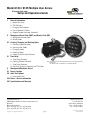
Model 6124 / 6125 Multiple User Access Electronic Safe Lock Setup and Operations Guide I. General Information a. b. c. d. e. About Your Lock PIN Positions Changing the Batteries Quick Reference Tables Keypad Tamper Indicator (Optional) II. Management Reset Code (MRC) and Master Code (MC) a. Management Reset Code b. Master Code III. Creating, Changing and Deleting Codes a. b. c. d. e. Creating Supervisor Code Creating User Codes Changing Codes Deleting Codes Detecting Active User Positions IV. Time Delay a. b. c. d. Time Delay Duration Opening Window Duration Time Delay Override Creating, Changing, Deleting the TDO Code Note: T his lock has been Listed by Underwriters Laboratories for use with the following S&G keypad(s): 6120-0XX, 6120-2XX, 6160-2XX (IP Series), 61KP-1XX, 61KP-2XX V. Management/Employee Access VI. Duress Function VII. Audit Trail Options a. Event Audit Trail VIII.Codes—General Information VIII.Specifications and Warranty Sargent & Greenleaf, Inc. A Wholly Owned Subsidiary of Stanley Security Solutions, Inc. PO Box 930 Nicholasville, KY 40356 Phone: (800)-826-7652 Fax: (800)-634-4843 Phone: (859)-885-9411 Fax: (859)-887-2057 Copyright© 2006, Sargent & Greenleaf, Inc. Sargent & Greenleaf S.A. 9, chemin du Croset 1024 Ecublens, Switzerland Phone: +41-21 694 34 00 Fax: +41-21 694 34 09 page Document 630-656ENG Revised 5/25/06 I. General Information a. About Your Lock Each time you press a number, letter, or other character on the keypad of your Model 6124 or 6125 electronic safe lock, it beeps and the red LED flashes. If it doesn’t, check your batteries to make sure they are fresh and connected properly, then try again. (See Changing the Batteries, paragraph C.) The lock responds with various beep () sequences to indicate different conditions. The symbols in examples show the number of beeps you hear. Always wait for each set of beeps to end before entering another number or letter, or you will interrupt the code sequence. Important points: •W hen programming, you enter new codes twice, to confirm their accuracy. •C learing the Lock: If you start to enter a code and make a mistake, you can press * to clear the lock, or wait 10 seconds and it will clear itself. Note: Do not wait more than 10 seconds between entries or the lock will clear. • Error Beep: If you hear a long continuous beep during any programming sequence, you made an error. Start the sequence over. • Error Penalty: If you enter five incorrect codes in a row, the lock starts a ten minute penalty time. If you enter another wrong code during this time, you’ll hear two long beeps, and the lock will not open. You have no recourse other than to wait ten minutes before entering a valid code to open the lock. b. PIN Positions Each code created for use in your lock is assigned a personal identification number (PIN) position. The Master Code is PIN 0 (zero), the Supervisor is PIN 1, Users are PINs 2 through 8. If your lock has the duress feature enabled, User PINs 4 through 8 are automatically disabled and are not available. The Time Delay Override Code uses PIN 9. If Time Delay Override is disabled, PIN 9 works like a standard User code. c. Changing the Batteries No codes or program settings are lost during battery replacement. Carefully remove the keypad housing by first lifting the bottom edge (closest to the S&G logo) and then easing it off the base. Detach the old batteries from the terminals. To prevent bending or breaking the holder, support the top of each battery holder as you insert each fresh battery; Duracell® alkaline batteries are recommended. Note: If power is removed from the lock in Management/Employee mode, the lock powers up in the disabled state. page d. Quick Reference Tables Command Reference: Each of the following commands (CMD) begins a code sequence to perform a specific function. CMD Function 22* Change six-digit user code. 28* Download the event audit trail. 32* Set up the Management/Employee enabling/disabling of user codes. 38* Enable/disable the duress function 43* Identify the type of lock. 46* Program the time delay override option. 55* Enable/disable user codes (with Master or Supervisor Code, in Management/Employee mode). 56* Set up user code disabling. 67* Define and use the Management Reset Code. 74* Program functions (require Master Code) - Define or change the time delay period (1-99 minutes) - Define or change the opening window (1-10 minutes) - Add/delete Supervisor Code Program functions (require Master or Supervisor Code) - Add user codes 2-8 - Delete user codes 1-8 - Create/delete a Time Delay Override Code (PIN 9) 77* Detect active PIN positions. Lock Identification: Enter 4 3 * and listen carefully for the lock identification beeps. Beep Set Lock Identification: Number of Beeps 1st set (high/short): Lock Model Deadlocking motor (6124) 4 beeps Push/pull motor (6125) 5 beeps 2nd set (low/long): Access Type Single User 1 beep Multiple User 2 beeps --Dual Control 3 beeps Reference for Beep Patterns Action/Condition What You Hear Wrong code entered 1 long continuous beep Code entered during error penalty time 2 long continuous beeps User code entered to start time delay 3 short high-pitch beeps Time delay countdown 1 short high-pitch beep every 10 seconds Time delay expiration signal 10 short high-pitch beeps Opening Window signal 2 short high-pitch beeps every 6 seconds Low Battery Warning 5 sets of 2 short high-pitch beeps Battery too low to perform functions 20 short high-pitch beep (code lockout) Bolt extension indicator 1 low/high beep sequence Keypad tamper signal (optional) 2 sequences of SOS (3 short-high, 3 short-low, 3 short-high) End of Audit Trail download 3 high pitch beeps Enable lock (Management/ Employee mode) 4 high pitch beeps Disable lock (Management/ Employee mode) 2 low pitch beeps page e. Keypad Tamper Indicator—Required for VdS rating (Optional: Tamper-indicating keypad must be ordered) If a tamper-indicating keypad is installed, the lock records each time the lock keypad housing is unseated or removed from the base. If the housing is disturbed, the Keypad Tamper Indicator beeps an SOS warning signal the next time you attempt to enter a valid access code. The lock will not open; it beeps the SOS: 3 short/high beeps, 3 short/low beeps, 3 short/high beeps. This signal is repeated twice. When it stops, enter a valid code within one minute and the Keypad Tamper Indicator will reset and the lock will open. Note: The keypad will not work when disconnected from the base. II. Management Reset Code and Master Code a. Management Reset Code Set up a Management Reset Code (MRC) to use if you need to reset the lock in the future. Resetting the lock deletes the time delay override code, supervisor code and user codes; you also create a new Master Code at the same time. Resetting the lock does not affect the time delay or opening window durations, duress, audit trail, lock access method or audit trail settings. Important! The MRC must be set up prior to changing the Master Code for the first time. The factory-set Master Code is 1 2 3 4 5 6. The first step in preparing for your lock operation is to decide if you want to use a Management Reset Code (MRC). If you do, we suggest that you store this code off the premises as an additional security measure. Note: The MRC may have been preset at the factory; a factory-set MRC can be changed using this procedure if the Master Code has not been changed. The Management Reset Code (MRC) must be a unique code with six digits; one of the digits must be 1/0 or 3/0. That is, when you enter the code, you will press the 1 or 3 simultaneously with 0 (zero). Examples of valid MRCs would be either of the following: 7 6 5 4 3/0 2 and 4 5 2 1/0 6 6. The combination of the two keys (1/0 or 3/0) provide added security. Be sure to listen for the beeps (*) as you enter the following: 6 7 * Factory-set Master Code # MRC # MRC # For example: 6 7 * 1 2 3 4 5 6 # 9 1/0 8 9 2 7 # 9 1/0 8 9 2 7 # 1. Using the MRC Use the MRC only when you know you have lost or forgotten the Master Code. Remember that the MRC deletes the Time Delay Override Code, the Supervisor Code and User Codes. You also create a new Master Code as you use the Management Reset Code (MRC). Enter: 6 7 * MRC # New Master Code # New Master Code # page For example, to use the MRC of 9, 1/0, 8, 9, 2, 7 and create a Master Code of 6, 5, 4, 3, 2, 1: 6 7 * 9 1/0 8 9 2 7 # 6 5 4 3 2 1 # 6 5 4 3 2 1 # 2. MRC Audit Trail This audit trail lets you know how many times the MRC has been used to reset the lock. Immediately after the new Master Code is set with the MRC, the lock beeps once for each time the MRC has been used, including the current usage. Note: Usage of the MRC is recorded in the event audit trail. b. Master Code The Master Code is used when entering commands for specific lock management functions. Once the Management Reset Code (MRC) parameter has been set, you need to change the Master Code (from the factory-set 1 2 3 4 5 6). To create a new 6-digit Master Code, enter it where the example says New Master Code: 2 2 * Current Master Code # New Master Code # New Master Code # For example, to change the factory-set Master Code to 654321: 2 2 * 1 2 3 4 5 6 # 6 5 4 3 2 1 # 6 5 4 3 2 1 # III. Creating, Changing and Deleting Codes a. Creating Supervisor Code Using the Master Code, you can create a Supervisor level code (PIN 1). The Supervisor Code can be used to manage the User Codes; it can add and delete User Codes, and enable and disable the lock operation in Management/Employee Access (see Section V). Make up a 6-digit Supervisor Code and enter: 7 4 * Master Code # 1 # Supervisor Code # Supervisor Code # page b. Creating User Codes Using the Master or Supervisor Code, create new User Codes. For each user, create a unique 6-digit code and assign a PIN position (2 through 8). PIN position 9 is also available as a normal User Code if the Time Delay Override feature is turned off. Note that PIN positions 4 through 8 are not available if the lock’s duress function is enabled. For example, to create a new user in PIN position 3, you would enter: 7 4 * Master or Supervisor Code # 3 # New User Code # New User Code # Security Note: After setting up a new User Code, it is recommended that each User change his/her code to a unique 6-digit code of their choice. c. Changing Codes The Master, Supervisor, Users and TDO code holders can change their own 6-digit codes using command 2 2 * (or alphabetic characters C C, for “Change Code”). Enter: 2 2 * Old User Code # New User Code # New User Code # d. Deleting Codes To delete the Supervisor or a specific User (the Master Code may be changed but not deleted), you only need to know the PIN position. The example below shows the deletion of the User in PIN 3. 7 3 # # 4 * Master or Supervisor Code # # e. Detecting Active User Positions You can identify active PIN positions for which codes are present (PIN 0-9). Each number on the keypad corresponds to a PIN position. Enter: 7 7 * [ 0, 1, 2, 3, 4, 5, 6, 7, 8, 9 ] PIN position If the lock beeps one high short beep when pressing a number key on the keypad, that PIN position is active. If it beeps one low long beep, it is not active. IV. Time Delay Time Delay is a security feature that creates a period of time between the entering of a valid code and the ability to open the safe door. Time delay can be set to delay opening from 1 to 99 minutes. Security Note: If time delay has already been set, changes to the opening window and time delay durations can only be made during the opening window period. page a. Time Delay Duration If the time delay parameter has been set and you want to change it, enter a user code to start the time delay. When Time Delay expires (the lock emits 10 rapid beeps) and the opening window period has begun, set your Time Delay minutes. Enter: 7 4 * Master Code # 0 0 # Time Delay minutes # Time Delay minutes # For example, to set the Time Delay to 15 minutes, enter: 7 0 1 1 4 0 5 5 * # # # Master Code # To eliminate the Time Delay period, simply enter zero (0) for the Time Delay minutes. b. Opening Window Duration The opening window (OW) is the period of time during which you can open the lock, immediately following the end of the time delay period. The OW can be set for 1 to 10 minutes; the factory default is 2 minutes. Security Note: Changes to the opening window duration can only be made during the opening window. To set the minutes for the Opening Window, enter: 7 4 * Master Code # 0 1 # Opening Window minutes # Opening Window minutes # For example, to set the Opening Window to 5 minutes, enter: 7 0 5 5 4 * Master Code # 1 # # # page c. Time Delay Override With Time Delay Override (TDO), you define whether or not you can override Time Delay, in case you need to open the lock before the time delay expires - for example, by a cash carrier. If time delay has been programmed, the following steps must be performed during the opening window period. Important Note: PIN position 9 is where the Time Delay Override Code is stored. If TDO is not activated (using one of the two following procedures), a code stored in PIN position 9 acts like a standard User Code. Type 1: Open Lock After Time Delay Begins With this option, you enter a TDO Code after a valid user has entered his/her code and the time delay period has begun. The TDO code must be entered in the first 60 seconds of the time delay period. To choose this type of override, enter: 4 6 * Master Code # 1 # 1 # Type 2: Open Lock Before Time Delay Begins With this option, you enter a TDO Code that allows the lock to be opened immediately without waiting for the time delay to be started. To choose this type of override, enter: 4 6 * Master Code # 2 # 2 # Turn Off Time Delay Override Important Note: The TDO Code (PIN position 9) is automatically deleted when TDO is turned off. It can then be re-programmed with a new code which will act as a standard User Code. To turn off the Time Delay Override completely after it’s been programmed, enter: 4 6 * Master Code # 0 # 0 # d. Creating, Changing, and Deleting a TDO Code To use the TDO feature, you need to create a unique 6-digit TDO code in PIN position 9. Note: The TDO code is created, changed and deleted the same as user codes. (See Section III. Creating, Changing and Deleting Codes.) page V. Management/Employee Access During everyday operation of the lock, the Manager or Supervisor ‘enables’ the lock, and the lock can then be opened by User Codes until it is “disabled”. There are two versions of the enable/disable function: • In the first version, only the Master and the Supervisor can both enable and disable the lock. • In the second version, Users may disable the lock (Master and Supervisor can still disable the lock). a. Program the Lock for Enable/Disable Operations as follows: 3 2 * Master Code # 2 # 2 # After this step, the lock is in the disabled mode. b. To enable all codes (Users, Master and Supervisor): 5 5 * Master or Supervisor Code # After this enabling command, Master, Supervisor or User codes can open the lock. c. To disable all codes: 5 5 * Master or Supervisor Code # No code can open the lock. Entry of any code results in the lock beeping 2 low tone beeps indicating the lock is disabled. d. Program the lock for a “special” user disable function with the following command: 5 6 * Master Code # 1 # 1 # e. After the lock is enabled by the Master or Supervisor code, any User code can disable lock by entering: 5 5 * User Code # Note: Master and Supervisor Codes can also disable the lock in the User Disable version. f. To turn off the “special” user disable function: 5 6 * Master Code # 0 # 0 # Now only the Master or Supervisor Code can disable the lock. g. To program the lock out of the enable/disable mode: 3 2 * Master Code # 1 # 1 # page VI. Duress Function (Order Duress Module Separately) Your lock has duress capability (a silent alarm option). Installation of a duress signal box (duress module) is required for proper connection to your existing alarm system. Use the instructions provided with the module to ensure accurate installation and connection. a. Enabling the Duress Feature When the lock is installed with the duress module, you need to enable duress feature. Note that doing so automatically deletes and disables User Codes 4 through 8. PIN positions 4 through 8 are not usable when duress is turned on. To turn on the duress feature, press: 3 8 * Master Code # 1 # 1 # When the duress feature is enabled, you can send a duress signal (silent alarm) by altering the last number of your lock code by plus 1. For example, if your code is 246812, you would enter 246813 to send the duress signal to your alarm company. When you use a duress code, the lock operates normally. a. Disabling the Duress Feature Disabling the duress feature automatically restores the functionality of PIN positions 4 through 8. You will be able to program User Codes into these positions. To turn off the duress feature, press: 3 8 * Master Code # 0 # 0 # VII. Audit Trail Options a. Event Audit Trail (Order Audit Trail Keypad Extension Separately) This function keeps a sequential record of lock opening and programming events. This Event Audit Trail is stored in the lock memory and can be downloaded to a computer (this requires the installation of a keypad extension). 2 8 * Master Code # The lock beeps 3 times () when the download is complete. VIII. Codes—General Information After changing the opening code, the lock should be opened and locked several times with the safe door open. Important: do not select codes such as birthdays or other predictable data which could provide a correlation between the user and the opening code. page 10 VIII. Specifications and Warranty Specifications for Models 6124 and 6125 Electronic Safe Locks and 61KP Keypads Lock Dimensions Width: 2.4” (61 mm) Height: 1.1” (30 mm) Length: 3.32” (84 mm) Keypad Dimensions 4 inches diameter (101 mm) Height: 1.44” (36 mm) Weight 6124: 1 pound (45 g) 6125: 1 pound (45 g) Housing/base: 0.7 pound (28 g) Shipping Weight 6124: 1.75 pounds (74 g) 6125: 1.75 pounds (74 g) Finish Case: Black paint Power Two (2) 9-volt alkaline batteries (Duracell® recommended) Battery Life Approximately 5,000 openings (based on use of Duracell® batteries). Note: Use of time delay will decrease battery life. Low Battery Detection Beep/LED flash feedback from keypad (5 double beeps/flashes) Operating Temperature 32 ° to 120° F (0° to 50° C) Fresh batteries are recommended at lower temperatures. Cover: Black paint Keypad: Satin chrome plated Note: This lock has been Listed by Underwriters Laboratories for use with the following S&G keypad(s): 6120-0XX, 6120-2XX, 6160-2XX (IP Series), 61KP-1XX, 61KP-2XX Models 6124 and 6125 Electronic Safe Lock and Model 61KP Keypad Limited Warranty Seller warrants that for two (2) years from the date of shipment from Seller’s point of manufacture, the goods will be free from defects in material and workmanship, provided the goods are normally and properly used according to the Seller’s written instructions. THIS WARRANTY IS EXPRESSLY MADE IN LIEU OF ANY AND ALL OTHER WARRANTIES, EXPRESS OR IMPLIED. S&G DOES NOT WARRANT THAT THE GOODS ARE MERCHANTABLE OR FIT FOR ANY PARTICULAR PURPOSE EXCEPT AS EXPRESSLY PROVIDED HEREIN. Seller’s entire liability and Buyer’s exclusive remedy in the event that the goods do not conform to the foregoing warranty shall be Seller’s repair or replacement of the goods (including payment of freight costs to and from point of manufacture). This warranty does not apply to batteries or damage from battery leakage. SELLER SHALL HAVE NO LIABILITY FOR ANY CONSEQUENTIAL, INCIDENTAL, INDIRECT OR SPECIAL DAMAGES. SELLER DOES NOT WARRANT ITS LOCK PRODUCTS TO BE IMPERVIOUS TO FORCIBLE OR SURREPTITIOUS ENTRY, AND SELLER SHALL HAVE NO LIABILITY FOR DAMAGE TO OR LOSS OF PROPERTY SOUGHT TO BE PROTECTED BY ANY SUCH LOCK. S&G Confidential The information contained in this document is proprietary to Sargent & Greenleaf, Inc. The existence of the Management Reset Code and the procedures under which it is implemented and used should be treated as confidential. Publication or duplication of this copyrighted document is strictly prohibited. Sargent & Greenleaf assumes no responsibility or liability for the dissemination or use of the Management Reset Code for any lock. page 11