1
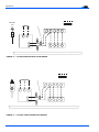
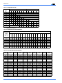
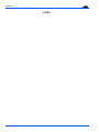
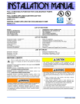
INSTALLATION
INSTRUCTIONS
STELLAR
AIR CONDITIONING UNIT
SPLIT-SYSTEM COOLING
CONTENTS
GENERAL . . . . . . . . . . . . . . . . . . . . . . . . . . . . . . . . . . . . . 2
NOMENCLATURE . . . . . . . . . . . . . . . . . . . . . . . . . . . 2
SAFETY . . . . . . . . . . . . . . . . . . . . . . . . . . . . . . . . . . . 2
INSPECTION . . . . . . . . . . . . . . . . . . . . . . . . . . . . . . . 2
LIMITATIONS . . . . . . . . . . . . . . . . . . . . . . . . . . . . . . . 2
LOCATION . . . . . . . . . . . . . . . . . . . . . . . . . . . . . . . . . . . . 3
GROUND INSTALLATION . . . . . . . . . . . . . . . . . . . . . 3
ROOF INSTALLATION . . . . . . . . . . . . . . . . . . . . . . . . 3
UNIT PLACEMENT . . . . . . . . . . . . . . . . . . . . . . . . . . . . . . 3
VERIFY INDOOR REFRIGERANT ORIFICE . . . . . . . 4
INSTALLATIONS REQUIRING TXV . . . . . . . . . . . . . 4
PIPING CONNECTIONS . . . . . . . . . . . . . . . . . . . . . . . . . . 5
PRECAUTIONS DURING LINE INSTALLATION . . . . 5
PRECAUTIONS DURING BRAZING OF LINES. . . . . 6
PRECAUTIONS DURING BRAZING
ANGLE VALVE . . . . . . . . . . . . . . . . . . . . . . . . . . 6 & 7
GENERAL INFORMATION & GROUNDING . . . . . . . . . . 8
FIELD CONNECTIONS POWER WIRING . . . . . . . . . . . . 8
FIELD CONNECTIONS CONTROL WIRING . . . . . . . . . . 8
SYSTEM CHARGE . . . . . . . . . . . . . . . . . . . . . . . . . . 8
MEASUREMENT METHOD . . . . . . . . . . . . . . . . . . . . 9
SUPERHEAT CHARGING METHOD . . . . . . . . . . . . 9
SYSTEM START-UP . . . . . . . . . . . . . . . . . . . . . . . . . . . . . 9
ENERGIZE CRANKCASE HEATER . . . . . . . . . . . . . 9
SYSTEM CONTROLLER - HDB076 ONLY . . . . . . . 13
INSTRUCTING THE OWNER. . . . . . . . . . . . . . . . . . 13
INDICATIONS OF PROPER OPERATION . . . . . . . 13
MAINTENANCE . . . . . . . . . . . . . . . . . . . . . . . . . . . . 13
MODELS:
10 SEER
11 SEER
12 SEER
50 Hz
H*DB012 - 76
H*DE024 - 60
H*DH018 - 60
H*DA018-076
CAUTION: READ ALL SAFETY GUIDES BEFORE
YOU BEGIN TO INSTALL YOUR UNIT.
SAVE THIS MANUAL
035-14562-000 REV A (999)
Form 550.38-N1Y (999)
550.38-N1Y
®
GENERAL
Installer should pay particular attention to the words: NOTE,
CAUTION and WARNING.
This instruction covers the installation of the following Stellar
air conditioning units.
NOTES are intended to clarify or make the installation easier.
NOMENCLATURE
CAUTIONS are given to prevent equipment damage.
H 4
DB
030 S 06
Product Category
WARNINGS are given to alert the installer that personal
injury and/or equipment damage may result if installation procedures are not handled properly..
H = Condensing Unit
Product Generation
4 = Design Level
This product must be installed in strict compliance
with the enclosed installation instructions and any
applicable local, state, and national codes including,
but not limited to, building, electrical, and mechanical
codes.
Product Identifier
DB = 10.00 SEER Condensing Unit
DE = 11.00 SEER Condensing Unit
DH = 12.00 SEER Condensing Unit
DA = 50 Hz Condensing Unit
Nominal Cooling Capacity
012 = 12,000 BTUH
018 = 18,000 BTUH
024 = 24,000 BTUH
030 = 30,000 BTUH
036 = 36,000 BTUH
042 = 42,000 BTUH
048 = 48,000 BTUH
060 = 60,000 BTUH
076 = 76,000 BTUH
Refrigerant Line Connections
INSPECTION
S = Sweat-Connect
Voltage Code
06 = 208/230-1-60 46 = 460-3-60
25 = 208/230-3-60
58 = 575-3-60
78 = 230-1-50
50 = 380/415-3-50
These outdoor units are designed to be connected to a
matching UPG indoor coil with sweat connection lines. These
units are factory charged with refrigerant for a matching
indoor coil plus 15 feet of field supplied line. The outside unit
is designed to be placed alongside or at the back of the
home, remote from the indoor coil. The outdoor unit has been
factory run-tested and all components of the system are
ready for easy, immediate installation.
Matching evaporators contain an orifice liquid feed sized for
the most common usage. The orifice size and/or refrigerant
charge may need to be changed for some indoor-outdoor unit
combinations, elevation differences or total line lengths.
SAFETY
Use this instruction in conjunction with the instruction for the
appropriate indoor evaporator coil, variable speed air handler
or furnace and other accessories. Read all instructions before
installing the unit.
2
Incorrect installation may create a condition where the
operation of the product could cause personal injury
or property damage.
As soon as a unit is received, it should be inspected for possible damage during transit. If damage is evident, the extent of
the damage should be noted on the carrier's freight bill. A
separate request for inspection by the carrier's agent should
be made in writing. See Form 50.15-NM for more information.
LIMITATIONS
The unit should be installed in accordance with all national
and local safety codes and the limitations listed below:
1.
Limitations for the indoor unit, coil and appropriate
accessories must also be observed.
2.
The outdoor unit must not be installed with any duct work
in the air stream. The outdoor fan is the propeller type
and is not designed to operate against any additional
external static pressure.
3.
The unit should not be operated at outdoor temperatures
below 45 °F.
4.
Indoor evaporator coil orifice must be removed prior to
the installation of a TXV kit if the system match requires
a TXV.
Unitary Products Group
550.38-N1Y
®
TO
BLOWER
MOTOR
RELAY
WEATHERPROOF
DISCONNECT
SWITCH
THERMOSTAT
TO POWER
SUPPLY
NEC CLASS 1
WIRING
48” OVERHEAD
CLEARANCE
12” REAR
REQUIRED
AND SIDES
CLEARANCE
REQUIRED
Sit unit on
rubber
elevator
grommets
to reduce
noise and
allow for
proper
drainage.
NEC CLASS 2
WIRING
TO
COIL
NOTE: ALL OUTDOOR WIRING
MUST BE WEATHERPROOF
24” SERVICE
ACCESS CLEARANCE
REQUIRED
SEAL OPENING(S) WITH PERMAGUM OR EQUIVALENT
FIGURE 1: TYPICAL INSTALLATION
LOCATION
Before starting the installation, select and check the suitability
of the location for both the indoor and outdoor unit. Observe
all limitations and clearance requirements.
The outdoor unit must have sufficient clearance for air
entrance to the condenser coil, for air discharge and for service access. See Figure 1.
If the unit is to be installed on a hot sun exposed roof or a
black-topped ground area, the unit should be raised sufficiently above the roof or ground to avoid taking the accumulated layer of hot air into the outdoor unit.
Normal operating sound levels may be objectionable if the
unit is placed directly under windows of certain rooms (bedrooms, study, etc.).
ROOF INSTALLATION
When installing units on a roof, the structure must be capable
of supporting the total weight of the unit, including a pad, lintels, rails, etc., which should be used to minimize the transmission of sound or vibration into the conditioned space.
UNIT PLACEMENT
1.
Provide a base in the pre-determined location.
2.
Remove the shipping carton and inspect for possible
damage.
GROUND INSTALLATION
3.
Compressor tie-down bolts should remain tightened.
The unit may be installed at ground level on a solid base that
will not shift or settle, causing strain on the refrigerant lines
and possible leaks. Maintain the clearances shown in Figure
1 and install the unit in a level position. Isolate the base from
the structure to avoid noise or vibration transmission.
4.
Position the unit on the base provided.
5.
Sit unit on the (4) rubber elevating grommets if provided.
Use grommet kit 1SG0601 if not provided. These should
be positioned as shown in Figure 2 to reduce noise and
allow for proper drainage.
Isolate the unit from rain gutters to avoid any possible wash
out of the foundation.
6.
Make a hole(s) in the structure wall large enough to
accommodate the insulated vapor line, the liquid line and
the wiring.
Provide an adequate structural support.
Unitary Products Group
3
550.38-N1Y
®
U N IT
B A S E
P A N
Coil is under 30 PSIG helium pressure. Relieve pressure from schrader valve on liquid line side.
R
E
G
(
N o tDe o
:
U B B E R
L E V A T IN G
R O M M E T S
4 )
N o t b lo c k
d r a in a g e
h o le s
w i t h This
g rfitting
o m isma e
ts .
right-hand
thread, turn counter-clock-
wise to remove.
U N IT
B A S E
P A N
R
E
G
(
FIGURE 2 :
1.
First, relieve the holding charge by depressing the
Schrader valve located in the end of the liquid line.
2.
Remove the liquid line fitting using 3/4" wrenches, and
remove the pre-installed orifice with a small diameter
wire or paper clip.
U B B E R
L E V A T I N 3.
G
R O M M E T S
4 )
POSITIONING GROMMETS
4.
Remove the new orifice from the packet and verify that it
is the correct number required. Install this orifice with the
rounded end toward the coil and the flat end outward per
Figure 3 on page 4.
Thread the liquid line fitting back in place on the coil.
Tighten the fitting hand tight and turn an additional 1/8
turn to seal.
VERIFY INDOOR REFRIGERANT ORIFICE
Refer to the Tabular Data Sheet for the outdoor unit model
and installed evaporator coil. Determine the correct orifice for
that combination.
If the orifice sizes match, nothing further is required and the
refrigerant lines may be connected per the outdoor unit
instruction. However, if another orifice should be used,
change the orifice in the coil with the following procedure:
L IQ U ID
L IN E
S W IV E L
C O U P L IN G
(S e e
C A U )T I O N
b e lo
O R IF IC E
Use 3/4" wrenches to turn fittings. Using pliers will
cause internal damage to the fitting.
NOTE: This procedure should be done within 2 minutes to
keep air and contaminates from entering the coil. If the
orifice cannot be replaced and the coil resealed within
2 minutes, then it should be temporarily closed to air
using masking tape (short term delay) or plugging/capping (long term delay). There is no need to purge the
w
coil if this procedure is done within the time limit.
5.
Mark the data plate of the coil with the orifice installed.
INSTALLATIONS REQUIRING TXV
D IS T R IB U T O R
FIGURE 3 : ORIFICE INSTALLATION
For installations requiring a TXV, the following are the basic
steps for installion. For detailed instructions, refer to the
Installation Instructions accompanying the TXV kit.
Install TXV kit as follows:
1.
4
First, relieve the holding charge by depressing the
Schrader valve located in the end of the liquid line.
Unitary Products Group
550.38-N1Y
®
Ensure the bulb is making maximum contact. Refer to TXV
installation instruction for view of bulb location.
The evaporator coil is under 30 psig pressure.
2.
3.
4.
After holding charge is completely discharged, loosen
and remove the liquid line fitting from the orifice distributor
assembly. Note that the fitting has right hand threads.
Remove the orifice from the distributor body using a
small diameter wire or paper clip. Orifice is not used
when the TXV assembly is installed.
After orifice is removed, install the thermal expansion
valve to the orifice distributor assembly with supplied fittings. Hand tighten and turn an additional 1/8 turn to
seal. Do not overtighten fittings.
5.
Reinstall the liquid line to the top of the thermal expansion valve. Hand modify the liquid line to align with casing opening.
6.
Install the TXV equalizer line into the vapor line as follows:
7.
In all cases, mount the TXV bulb after vapor line is
brazed and has had sufficient time to cool.
a.
Select a location on the vapor line for insertion of the
equalizer line which will not interfere with TXV bulb
placement.
b.
Use an awl to punch through the suction tube and
insert the awl to a depth to achieve a 1/8 inch diameter hole.
Install TXV equalizer line in 1/8 hole previously made in
vapor line. Equalizer line can be bottomed out in vapor
line as end of equalizer line is cut on 45 degrees angle to
prevent blockage. Braze equalizer line making sure that
tube opening is not brazed closed.
Dry nitrogen should always be supplied through the
tubing while it is being brazed, because the temperature required is high enough to cause oxidation of the
copper unless an inert atmosphere is provided. The
flow of dry nitrogen should continue until the joint has
cooled. Always use a pressure regulator and safety
valve to insure that only low pressure dry nitrogen is
introduced into the tubing. Only a small flow is necessary to displace air and prevent oxidation.
Unitary Products Group
Bulb should be installed on a horizontal run of the
vapor line if possible. On lines under 7/8" OD the
bulb may be installed on top of the line. With 7/8"
OD and over, the bulb should be installed at the
position of about 4 or 8 o'clock.
b.
If bulb installation is made on a vertical run, the bulb
should be located at least 16 inches from any bend,
and on the tubing sides opposite the plane of the
bend. On vertical bulb installations, the bulb should
be positioned with the bulb tail at the top, so that the
bulb acts as a reservoir.
c.
Bulb should be insulated using thermal insulation
provided to protect it from the effect of the surrounding ambient temperature.
PIPING CONNECTIONS
The outdoor condensing unit may be connected to the indoor
evaporator coil using field supplied refrigerant grade copper
tubing that is internally clean and dry. Units should be
installed only with the tubing sizes for approved system combinations as specified in Tabular Data Sheet. The charge
given is applicable for total tubing lengths up to 15 feet. See
Application Data Form 690.01-AD1V for installing tubing of
longer lengths and elevation differences.
NOTE: Using a larger than specified line size could result in oil
return problems. Using too small a line will result in loss
of capacity and other problems caused by insufficient
refrigerant flow. Slope horizontal vapor lines at least 1"
every 20 feet toward the outdoor unit to facilitate proper
oil return.
PRECAUTIONS DURING LINE INSTALLATION
1.
Install the lines with as few bends as possible. Care must
be taken not to damage the couplings or kink the tubing.
Use clean hard drawn copper tubing where no appreciable amount of bending around obstruction is necessary.
If soft copper must be used, care must be taken to avoid
sharp bends which may cause a restriction.
2.
The lines should be installed so that they will not obstruct
service access to the coil, air handling system or filter.
3.
Care must also be taken to isolate the refrigerant lines to
minimize noise transmission from the equipment to the
structure.
All connections to be brazed are copper-to-copper and
should be brazed with a phosphorous-copper alloy material
such as Silfos-5 or equivalent. DO NOT use soft solder.
Install the TXV bulb to the vapor line near the equalizer line,
using the two bulb clamps furnished with the TXV assembly.
a.
5
550.38-N1Y
4.
®
The vapor line must be insulated with a minimum of 1/2"
foam rubber insulation (Arm-A-Flex or equivalent). Liquid
lines that will be exposed to direct sunlight and/or high
temperatures must also be insulated.
Dry nitrogen should always be supplied through the
tubing while it is being brazed, because the temperature required is high enough to cause oxidation of the
copper unless an inert atmosphere is provided. The
flow of dry nitrogen should continue until the joint has
cooled. Always use a pressure regulator and safety
valve to insure that only low pressure dry nitrogen is
introduced into the tubing. Only a small flow is necessary to displace air and prevent oxidation.
Tape and suspend the refrigerant lines as shown. DO NOT
allow metal-to metal contact. See Figure 4.
5.
Use PVC piping as a conduit for all underground installations as shown in Figure 5. Buried lines should be kept
as short as possible to minimize the build up of liquid
refrigerant in the vapor line during long periods of shutdown.
L I QUI D
L I NE
The outdoor units have re-usable service valves on both the
liquid and vapor connections. The total system refrigerant
charge is retained within the outdoor unit during shipping and
installation. The re-usable service valves are provided to
evacuate and charge per this instruction.
T AP E
INCORRECT
SHEET METAL HANGER
CORRECT
FIGURE 4 :
INSULATED VAPOR LINE
PVC
PRECAUTIONS DURING BRAZING ANGLE VALVE
Precautions should be taken to prevent heat damage to
angle valve by wrapping a wet rag around it as shown in Figure 6. Also, protect all painted surfaces and insulation during
brazing. After brazing - cool joint with wet rag.
TUBING HANGER
TO INDOOR COIL
LIQUID LINE
Serious service problems can be avoided by taking adequate
precautions to assure an internally clean and dry system.
TO OUTDOOR UNIT
INSULATED
CAP
VAPOR LINE
This is not a backseating valve. The service access
port has a valve core. Opening or closing valve does
not close service access port.
CONDUIT
FIGURE 5 :
6.
7.
If the valve stem is backed out past the retaining ring,
the O-ring can be damaged causing leakage or system pressure could force the valve stem out of the
valve body possibly causing personal injury. In the
event the retaining ring is missing, do not attempt to
open the valve.
UNDERGROUND INSTALLATION
Pack fiber glass insulation and a sealing material such
as permagum around refrigerant lines where they penetrate a wall to reduce vibration and to retain some
flexibility.
Connect the refrigerant lines using the following procedure:.
1.
Remove the cap and Schrader core from both the liquid
and vapor angle valve service ports at the outdoor unit.
Connect low pressure nitrogen to the liquid line service
port.
2.
Braze the liquid line to the liquid valve at the outdoor
unit. Be sure to wrap the valve body with a wet rag. Allow
the nitrogen to continue flowing.
See Form 690.01-AD1V for additional piping information.
PRECAUTIONS DURING BRAZING OF LINES
All outdoor unit and evaporator coil connections are copperto-copper and should be brazed with a phosphorous-copper
alloy material such as Silfos-5 or equivalent. DO NOT use
soft solder.
6
Unitary Products Group
550.38-N1Y
®
7.
Replace the schrader cores in the liquid and vapor
valves.
8.
Evacuate the vapor line, evaporator and the liquid line, to
500 microns or less.
9.
Leak test all refrigerant piping connections including the
service port flare caps to be sure they are leak tight. DO
NOT OVERTIGHTEN (between 40 and 60 inch - lbs.
maximum).
NOTE: Do not use the system refrigerant in the outdoor unit to
purge or leak test.
10. Replace caps on service ports. Do not remove the flare
caps from the service ports except when necessary for
servicing the system.
FIGURE 6 :
HEAT PROTECTION
Do not connect manifold gauges unless trouble is
suspected. Approximately 3/4 ounce of refrigerant
will be lost each time a standard manifold gauge
is connected.
If visual verification of the valve stem reaching the
retaining ring is impossible, stop backing out the.valve
stem when the slightest increase in resistance is felt.
Because of the small size and therefore the reduced
resistance, back out the liquid valve 5 turns maximum
to prevent going past the retaining ring.
3.
Carefully remove the brazed plugs from the evaporator
liquid and vapor connections after relieving the pressure
in the evaporator.
The evaporator is pressurized.
4.
Braze the liquid line to the evaporator liquid connection.
The nitrogen should now be flowing through the evaporator
coil.
5.
Slide the grommet away from the vapor connection at
the coil. Braze the vapor line to the evaporator vapor
connection. After the connection has cooled, slide the
grommet back into original position.
6.
Protect the vapor valve of the outdoor unit with a wet rag
and braze the vapor line connection. The nitrogen flow
should be exiting the system from the vapor service port
connection. After this connection has cooled, remove the
nitrogen source from the liquid fitting service port.
Unitary Products Group
11. Release the refrigerant charge into the system. Open
both the liquid and vapor valves by removing the plunger
cap and with an allen wrench back out counter-clockwise
until valve stem just touches retaining ring. Release the
refrigerant charge into the system. See “PRECAUTIONS
DURING BRAZING ANGLE VALVE” on page 6.
Replace plunger cap finger tight, then tighten an additional
1/12 turn (1/2 hex flat). Cap must be replaced to prevent
leaks.
If a leak is suspected, leak test to locate the leak. To verify
the leak, close the valve to the vacuum pump suction to isolate the pump and hold the system under vacuum. If the
micron gauge indicates a steady and continuous rise after a
few minutes, it's an indication of a leak. If the gauge shows a
rise, then levels off after a few minutes and remains fairly
constant, its an indication that the system is leak free, but still
contains moisture and may require further evacuation if the
reading is above 1000 microns.
12. If the refrigerant tubing, indoor evaporator coil or outdoor
condensing unit has developed a leak during shipment,
or was, for any other reason, opened to the atmosphere
for more than four (4) minutes, it is necessary to evacu-
7
550.38-N1Y
®
ate the system down to at least 500 microns to eliminate
contamination and moisture in the system.
CONTROL
WIRING
POWER
WIRING
LOW VOLTAGE
JUNCTION BOX
GROUND
LUG
Never attempt to repair any brazed connections while
the system is under pressure. Personal injury could
result.
See “SYSTEM START-UP” on page 9 for checking and
recording system charge.
GENERAL INFORMATION & GROUNDING
Check the electrical supply to be sure that it meets the values
specified on the unit nameplate and wiring label.
Power wiring, control (low voltage) wiring, disconnect
switches and over current protection to be supplied by the
installer. Wire size should be sized per NEC requirements.
All field wiring must USE COPPER CONDUCTORS
ONLY and be in accordance with Local, National Fire,
Safety & Electrical Codes. This unit must be grounded
with a separate ground wire in accordance with the
above codes.
The complete connection diagram and schematic wiring label
is located on the inside surface of the unit electrical box cover
and this instruction.
All outdoor wiring must
be weatherproof. Use
copper conductors only.
FIGURE 7 :
2.
The complete connection diagram and schematic wiring
label is located on the inside surface of the unit electrical
box cover.
3.
All field wiring to be in accordance with national electrical
codes (NEC) and/or local-city codes.
NOTE: A Start Assist Kit is available and recommended for
long line set applications or in areas of known low voltage problems. A hard start kit must be used if a solenoid
valve accessory or non-bleed type expansion device is
installed.
4.
Mount the thermostat about 5 ft. above the floor, where it
will be exposed to normal room air circulation. Do not
place it on an outside wall or where it is exposed to the
radiant effect from exposed glass or appliances, drafts
from outside doors or supply air grilles.
5.
Route the 24-volt control wiring (NEC Class 2) from the
outdoor unit to the indoor unit and thermostat.
FIELD CONNECTIONS POWER WIRING
1.
Install the proper size weatherproof disconnect switch
outdoors and within sight of the unit.
2.
Run power wiring from the disconnect switch to the unit.
3.
Remove the control box cover to gain access to the unit
wiring. Route wires from disconnect through power wiring opening provided and into the unit control box as
shown in Figure 7.
4.
Install the proper size time-delay fuses or circuit breaker,
and make the power supply connections.
5.
Energize the crankcase heater to save time by preheating the compressor oil while the remaining installation is
completed.
FIELD CONNECTIONS CONTROL WIRING
1.
8
Route low voltage wiring into bottom of control box as
shown in Figure 7. Make low voltage wiring connections
inside the junction box per Figures 8, 9, 10 or 11.
TYPICAL FIELD WIRING
NOTE: To eliminate erratic operation, seal the hole in the wall
at the thermostat with permagum or equivalent to prevent air drafts affecting the anticipators in the thermostat.
SYSTEM CHARGE
The factory charge in the outdoor unit includes enough
charge for the unit and a most sold matched evaporator.
Some indoor coil matches may require some additional
charge. See Tabular Data sheet provided in unit literature
packet.
Sweat connect units also include sufficient charge for 15 feet
of lines. See Tabular Data for charge adder for line lengths
greater than 15 feet.
Unitary Products Group
550.38-N1Y
®
The “TOTAL SYSTEM CHARGE” must be permanently
stamped on the unit data plate.
Total system charge is determined as follows:
1.
Determine outdoor unit charge from tabular data sheet.
2.
Determine indoor coil adjustment from tabular data
sheet.
3.
Calculate the line charge using the Tabular Data Sheet.
a.
Calculate total length of pre-charged lines for quick
connect units.
b.
Calculate over 15 feet of sweat lines for sweat connect units.
NOTE: The charge for pre-charged lines should be included
in the system charge shown on the data plate but need
not be added to the system. If sweat connect lines are
used, the line charge over 15 feet should be included
on the data plate and must be added to the system.
4.
Total system charge = item 1 + item 2 + item 3.
5.
Permanently stamp the unit data plate with the total
amount of refrigerant in the system.
Use one of the following charging methods whenever additional refrigerant is required for the system charge.
1.
Operate system until temperatures and pressures stabilize (minimum of 10 minutes).
2.
Measure and record indoor wet bulb (WB) temperature
using a sling psychrometer and the outdoor dry bulb
(DB) temperature using a thermometer.
3.
Measure and record the suction pressure at the suction
service valve port.
4.
Using Table 1 on page 12, note the superheat value corresponding to the intersection of the indoor wet bulb and
the outdoor dry bulb.
5.
With the superheat value obtained in step 4 and the suction pressure value from step 3, find the intersection of
the values in Table 2 on page 12. This is the required
suction tube temperature at the suction service valve.
6.
To bring the tube temperature in line with the required
value from Table 2, add refrigerant to the service port to
cause the tube temperature to fall and reclaim refrigerant
to cause the temperature to rise.
Check flare caps on Schrader fittings to be sure they are
tight. DO NOT OVERTIGHTEN (40-60 inch-lbs. maximum).
SYSTEM START-UP
ENERGIZE CRANKCASE HEATER
If this unit is equipped with a crankcase heater for the compressor, a warning label with an adhesive back is supplied in
the unit installation instruction packet. This label should be
attached to the field supplied disconnect switch where it will
be easily seen. See below:
Refrigerant charging should only be carried out by a
qualified air conditioning contractor.
In order to energize the crankcase heater:- Set indoor two
stage cooling thermostat to "OFF" position.- Close the line
power disconnect to the unit.
Measurement Method
If a calibrated charging cylinder or accurate weighing device
is available, add refrigerant accordingly.
IMPORTANT
An attempt to start the compressor without at least 8
hours of crankcase heat will damage the compressor
Compressor damage will occur if system is improperly
charged. On new system installations charge system
per tabular data sheet for the matched coil and follow
guidelines in this instruction.
Check flare caps on service ports to be sure they are leak
tight. DO NOT OVERTIGHTEN (between 40 and 60 inch lbs. maximum).
Superheat Charging Method
NOTE: Use this method only during system maintenace and
repair.
Unitary Products Group
9
550.38-N1Y
®
A L L
F IE L D
W IR IN G
T O
B E
IN
A C C O R D A N C E
W IT H
N A T IO N
P O W E R
P O W E R
W I2R 4I NV GO L T
C O N T R O L
W IR IN G
2 0 8 /2 3 0
1
6
0
C
O N T R O L
M in im u m
1 8
G A . W ir e
2 3 0 (- N1 E
-5
C 0 C la s s
2 )
F A C T O R Y
GROUND.
LUG
F U R N A C E
C
Y
O R
R
A IR
G
*
C O IL
Y
R
G
R O O M
O U T D O O R
W IR IN G
T E R M IN
W
C O N T A C T O R
T E R M IN A L S
A L L
H A N D L E R
W
*
T e r m in a l W
is
o n
r e q u ir e d
o n
s y s t
w ith
h e a t.
T H E R M O S T A T
M U S T
B E
W E A T H E R P R O O F .
FIGURE 8 : TYPICAL SINGLE PHASE FIELD WIRING
A L L
F IE L D
W IR IN G
T O
P O W E R
W IR IN G
2 0 8 /2 3 0 -3 -6
2 4
V O
4 6 0 -3 -6 0
M in im
3 8 0 /4 1 5 -3 -5
(N E C
B E
IN
A C C O R D A N C E
0
L T
C O N T R O L
W
u m
1 8
G A . W ir
0
C la s s
2 )
F U R N A C E
C
Y
O R
R
G
W IT H
N A T IO
P O W E R
I
C RO INN TG R O L
e
F A C T O R Y
A IR
H A N D L E R
T E R M IN A
W
C O N T A C T O R
T E R M IN A L S
G R O U N D
S C R E W
A L L
C O IL
O U T D O O R
R O O M
T e r m in a l
o n ly
re q
o n
s y s te
T H E R M O wSiTt h
A Th e a
M U S T
B E D WU EC AT TO HR ES R P
O R
N O
L Y
O .
F .
Y
W IR IN G
R
G
W
*
*
W
is
u ir e d
m s
t.
FIGURE 9 : TYPICAL THREE PHASE FIELD WIRING
10
Unitary Products Group
U
550.38-N1Y
®
A L L F IE L D W IR IN G
T O
B E IN A C C O R D A N C E W IT H N A T IO N A L E L E C T R IC A L C O D E (N E C ) A N D /O R L O C A L C O D E S
P O W E R
W IR IN G
2 0 8 /2 3 0 -3 -6 0
4 6 0 -3 -6 0
3 8 0 /4 1 5 -3 -5 0
5 7 5 -3 -6 0
P O W E R
C O N T R O L
F A C T O R Y
A IR
H A N D L E R
T E R M IN A L
B L O C K 4 T B
2 4 V O L T
C O N T R O L
W IR IN G
L 1
L 2
L 3
O U T D O O R
S E C T IO N
R E D
R
C
Y
G R O U N D
S C R E W
A L L
R
R
B
Y
Y
C
G
W*
X
5 3
B R N
G
Y E L
6 0
*
6 6
X
O U T D O O R
T Y P IC A L
C O O L IN G
T H E R M O S T A T
W IR IN G
M U S T
T e r m in a l W
r e q u ir e d o n
w ith h e a t.
B ED U
W CE TA OT RH SE R OP NR LOYO. F .
FIGURE 10 : TYPICAL FIELD WIRING - AIR HANDLER (H*DB076 & H*DA076 ONLY)
ALL FIELD WIRING TO BE IN ACCORDANCE WITH NATIONAL ELECTRICAL CODE (NEC) AND/OR LOCAL CODES
POWER WIRING
208/230-3-60
460-3-60
380/415-3-50
575-3-60
POWER
CONTROL
FACTORY
FURNACE TERMINAL BLOCK
C
L1
L2
L 3
R
C
GROUND
SCREW
Y
Y
R
G
W
Y
R
G
W
24 VOLT
CONTROL
WIRING
OUTDOOR
SECTION
ROOM THERMOSTAT
BRN
YEL
X
ALL OUTDOOR WIRING MUST BE WEATHERPROOF. USE COPPER CONDUCTORS ONLY.
FIGURE 11 : TYPICAL FIELD WIRING - FURNACE (H*DB076 & H*DA076 ONLY)
Unitary Products Group
is
s y
11
550.38-N1Y
®
Table 1: SUPERHEAT VALUE
OUTDOOR DB°F
INDOOR WB
°F1
55
9
12
14
17
20
23
26
29
32
35
50
52
54
56
58
60
62
64
66
68
70
72
74
76
1.
60
7
10
12
15
18
21
24
27
31
33
35
65
70
6
10
14
16
19
22
24
30
30
33
35
7
10
13
16
19
21
24
27
30
33
75
6
9
12
16
18
23
24
28
30
34
80
85
90
95
100
105
110
115
5
8
12
15
18
21
25
28
31
35
6
8
11
15
19
22
26
30
33
5
9
11
16
20
24
27
31
6
9
14
18
20
25
29
6
12
15
20
23
27
9
13
17
22
26
6
11
15
20
25
8
14
18
23
Evaporator Entering Air °F
Table 2: TEMPERATURE AND PRESSURE
SUCTION
PRESSURE
PSIG
(SERVICE
PORT)
SUCTION SERVICE VALVE SUPERHEAT °F
01
2
4
6
8
10
12
14
16
18
20
22
24
26
28
30
32
34
61.5
35
37
39
41
43
45
47
49
51
53
55
57
59
61
63
65
67
69
64.2
67.1
70.0
73.0
37
39
41
43
39
41
43
45
41
43
45
47
43
45
47
49
45
47
49
51
47
49
51
53
49
51
53
55
51
53
55
57
53
55
57
59
55
57
59
61
57
59
61
63
59
61
63
63
61
63
65
67
63
65
67
69
65
67
69
71
67
69
71
73
69
71
73
75
71
73
75
77
76.0
45
47
49
51
53
55
57
59
61
63
65
67
69
71
73
75
77
79
79.2
47
49
51
53
55
57
59
61
63
65
67
69
71
73
75
77
79
81
82.4
49
51
53
55
57
59
61
63
65
67
69
71
73
75
77
79
81
83
1.
Saturation Temperature
Table 3: R-22 SATURATION PROPERTIES
TEMP. °F
PRESSURE
PSIG
TEMP. °F
PRESSURE
PSIG
TEMP. °F
PRESSURE
PSIG
TEMP. °F
PRESSURE
PSIG
TEMP. °F
PRESSURE
PSIG
45
76.02
60
101.62
75
132.22
90
168.40
105
210.75
46
47
48
49
77.58
79.17
80.77
82.39
61
62
63
64
103.49
105.39
107.32
109.26
76
77
78
79
134.45
136.71
138.99
141.30
91
92
93
94
171.02
173.67
176.35
179.06
106
107
108
109
213.81
216.90
220.02
223.17
50
51
84.03
85.69
65
66
111.23
113.22
80
81
143.63
145.99
95
96
181.80
184.56
110
111
226.35
229.56
52
87.38
67
115.24
82
148.37
97
187.36
112
232.80
53
54
89.08
90.81
68
69
117.28
119.34
83
84
150.78
153.22
98
99
190.18
193.03
113
114
236.08
239.38
55
56
57
92.56
94.32
96.11
70
71
72
121.43
123.54
125.67
85
86
87
155.68
158.17
160.69
100
101
102
195.91
198.82
201.76
115
116
117
242.72
246.10
249.50
58
59
97.93
99.76
73
74
127.83
130.01
88
89
163.23
165.80
103
104
204.72
207.72
118
119
252.94
256.41
12
Unitary Products Group
550.38-N1Y
®
SYSTEM CONTROLLER - HDB076 ONLY
INDICATIONS OF PROPER OPERATION
Controls operation as follows:
Cooling operation is the same as any conventional air conditioning unit.
1.
2.
3.
4.
RANDOM START - Upon initial application of power and
a 2.5 second time delay, the compressor contactor will
be energized.
ANTI-SHORT CYCLE - Once the unit is energized, a
momentary interruption of power, i.e., thermostat cycling,
greater than 8 milliseconds, will initiate the compressor
lockout time delay of five minutes regardless of the condition of the inputs. Upon completion of the 5 minute
lockout delay the system will automatically reset allowing
the compressor contactor to energize.
SAFETY SWITCH - Upon interruption of power to the
compressor via the high pressure or low pressure switch,
the compressor contactor will be locked out indefinitely.
Reset will occur when the pressure switch recloses and
power has been removed and reapplied via the system
circuit breaker or by cycling the thermostat temperature
setting from maximum cool to maximum heat and back
to desired cool setting. During lockout the fault indicating
lamp shall be on.
LOW PRESSURE SWITCH BY-PASS TIME DELAY The low pressure switch is by-passed for a period of 75 105 seconds to allow the system to start and stablize.
After the delay period has expired the system will then
be maintained by the low pressure switch. In the event
that the low pressure switch should open after the delay
period while the compressor is running the system will
go into lockout. Note depending upon how the system is
wired the lockout may automatically be reset or may
require a manual reset.
System Time Delays are as follows: Random Start = 2.5 seconds; Lockout = 5 minutes; Low Pressure By-pass = 75 - 105
seconds.
The following checks may be made to determine if the system is operating properly:
1.
The outdoor fan should be running, with warm air being
discharged from the top of the unit.
2.
The indoor blower (furnace or air handler) will be operating, discharging cool air from the ducts.
3.
The vapor line at the outdoor unit will feel cool to the
touch.
4.
The liquid line at the outdoor unit will feel warm to the
touch.
If unit is not operating properly, check the following items
before calling a serviceman:
1.
Indoor section for dirty filter.
2.
Outdoor section for leaf or debris blockage.
Eliminate problem, turn off the thermostat for 10 seconds and
attempt start. Wait 5 minutes. If system does not start, call
service technician.
MAINTENANCE
1.
Dirt should not be allowed to accumulate on the outdoor
coils or other parts in the air circuit. Clean as often as
necessary to keep the unit clean. Use a brush, vacuum
cleaner attachment, or other suitable means.
2.
The outdoor fan motor is permanently lubricated and
does not require periodic oiling.
3.
If the coil needs to be cleaned, it should be washed with
Calgon CalClean (mix one part CalClean to seven parts
water). Allow solution to remain on coil for 30 minutes
before rinsing with clean water. Solution should not be
permitted to come in contact with painted panel surfaces.
4.
Refer to the furnace or air handler instructions for filter
and blower motor maintenance.
5.
The evaporator coil drain pan should be inspected and
cleaned regularly to prevent odors and assure proper
drainage.
INSTRUCTING THE OWNER
Assist owner with processing warranty cards. Review Owners
Guide and provide a copy for the owner guidance on proper
operation and maintenance. Instruct the owner or the operator how to start, stop and adjust temperature setting.
When applicable, instruct the owner that the compressor is
equipped with a crankcase heater to prevent the migration of
refrigerant to the compressor during the “OFF” cycle. The
heater is energized only when the unit is not running. If the
main switch is disconnected for long periods of shut down, do
not attempt to start the unit until 8 hours after the switch has
been connected. This will allow sufficient time for all liquid
refrigerant to be driven out of the compressor.
WHEN THE SYSTEM IS FUNCTIONING PROPERLY AND
THE OWNER HAS BEEN FULLY INSTRUCTED, SECURE
THE OWNER'S APPROVAL.
The installer should also instruct the owner on proper operation and maintenance of all other system components.
Unitary Products Group
13
550.38-N1Y
®
NOTES:
14
Unitary Products Group
550.38-N1Y
®
NOTES:
Unitary Products Group
15
550.38-N1Y
®
NOTES:
®
Heating and Air Conditioning
Unitary Products Group
5005 York Drive, Norman, Oklahoma 73069
Subject to change without notice. Printed in U.S.A.
Copyright © by Unitary Products Group 1999. All rights reserved.
Supersedes: 550.38-N1Y (899)
550.38-N1Y (999)