1
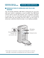
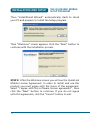
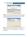
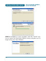
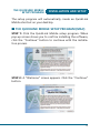
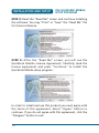
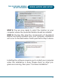
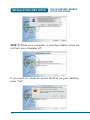
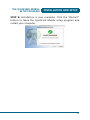
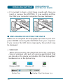
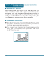
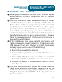
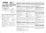
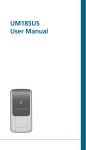
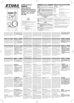
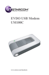
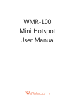
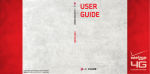
UM175US
Wireless USB Modem
User Manual
TABLE OF CONTENTS
CHAPTER 1
BEFORE USING UM175US ..............................................3
ABOUT THIS USER MANUAL ............................................................4
PRODUCT OVERVIEW ......................................................................4
WHAT’S INSIDE THE PRODUCT PACKAGE .......................................4
INTRODUCTION TO WIRELESS UM175US USB MODEM ..................5
PRODUCT FEATURES ........................................................................6
PRODUCT HANDLING ......................................................................7
CONFIGURATION .............................................................................7
CHAPTER 2
INSTALLATION AND SETUP ............................................9
THE QUICKLINK MOBILE SETUP PROGRAM (WIN) ........................11
THE QUICKLINK MOBILE SETUP PROGRAM (MAC).......................15
CHAPTER 3
USING QUICKLINK MOBILE ..........................................21
FEATURES ......................................................................................22
GETTING STARTED .........................................................................23
THE QUICKLINK MOBILE INTERFACE.............................................23
ESTABLISHING CDMA CONNECTIONS ...........................................25
CHAPTER 4
MOBILE PROPERTIES ....................................................27
MOBILE ADAPTER INFO ................................................................28
DEVICE TAB ...................................................................................28
NETWORK TAB ...............................................................................29
EVENT VIEWER ..............................................................................30
EVENT HISTORY .............................................................................31
CHAPTER 5
QUICK LINK MOBILE SETTINGS ...................................33
ACCESSING THE SETTINGS WINDOW ............................................34
APPLICATION TAB ..........................................................................35
ADDING AN APPLICATION ............................................................36
EDITING THE PARAMETERS FOR A LAUNCHED APPLICATION......37
MONITORING APPLICATIONS ........................................................40
1
TABLE OF CONTENTS
APPLICATION CONFIGURATION WINDOW ....................................41
MONITOR DETAILS WINDOW ........................................................42
SETTINGS: HARDWARE..................................................................43
SETTINGS: CONNECTION TIMEOUT ...............................................45
CHAPTER 6
INSTALLING UM175US .................................................47
PRECAUTIONS ...............................................................................48
RECOMMENDED SYSTEM REQUIREMENTS .................................48
INSTALLING SOFTWARE ...............................................................49
UNPLUGGING OR EJECTING THE DEVICE .....................................50
USB MODEM EXTENSION CABLE ..................................................52
CHAPTER 7
REGULATORY AND
SAFETY INFORMATION ................................................55
REGULATORY NOTICES .................................................................56
OPERATING CONDITIONS .............................................................56
WARNINGS AND CAUTIONS .........................................................57
SAFETY PRECAUTIONS ................................................................58
CHAPTER 8
APPENDIX ....................................................................61
GLOSSARY .....................................................................................62
SPECIFIC ABSORPTION RATES (SAR).............................................65
SAFETY INFORMATION FOR RF EXPOSURE ...................................67
U.S.FEDERAL COMMUNICATIONS COMMISSIONRADIO
FREQUENCY INTERFERENCE STATEMENT .....................................69
2
CHAPTER 1
BEFORE USING
UM175US
ABOUT THIS USER MANUAL
PRODUCT OVERVIEW
WHAT’S INSIDE THE PRODUCT PACKAGE
INTRODUCTION TO WIRELESS UM175US
USB MODEM
PRODUCT FEATURES
PRODUCT HANDLING
CONFIGURATION
BEFORE USING UM175US
ABOUT THIS USER
MANUAL
■ ABOUT THIS USER MANUAL
You will find all the information you need to install and
use the UM175US in this user manual. Before using the
UM175US, you must properly install the QuickLink Mobile by
closely following the installation instructions.
INSTRUCTIONS
• Install the QuickLink Mobile BEFORE inserting the UM175US
USB Device into your computer. The installation software
is included in the product package. Insert the CD into your
CD-ROM drive. Installation may take a few minutes.
• It is highly recommended that you read the safety precautions described in this manual before using the UM175US.
■ PRODUCT OVERVIEW
Thank you for purchasing the US Cellular Wireless UM175US
USB Modem. The UM175US is a 3G wireless device that
enables high-speed wireless communication from your computer. The UM175US is simple to install and use.
■ WHAT’S INSIDE THE PRODUCT PACKAGE
The following items are included in the product package.
If any of the items listed below are missing, please contact
the retail location where you purchased the product.
• UM175US Wireless USB Modem
• Installation CD that contains software and this user manual
• USB Modem Extension Cable
• Quick Start Guide
4
INTRODUCTION TO
UM175US USB MODEM
BEFORE USING UM175US
■ INTRODUCTION TO WIRELESS UM175US USB
MODEM
The US Cellular Wireless UM175US is designed for your PC’s
USB port, which is available in most models. The UM175US
can be used to access the Internet, your company’s intranet,
or you can use it to send and receive email. It is extremely
useful when you are away from the office, on the road, or
wherever a wireline Internet access is not readily available.
LED status
indicator *
External Antenna
Booster Jack
(on the left side)
Release button
USB Connector
* Blue light: Connected to computer and detected to network
Red light: Connected to computer but out of service status
5
BEFORE USING UM175US
PRODUCT FEATURES
■ PRODUCT FEATURES
• Power management: The UM175US utilizes power management and system overhead reduction functions provided by the USB interface for maximum power savings.
• Antenna design: Efficient, innovative internal antenna
design optimizes data transfer rate and sensitivity to network signals.
• Extension Y Cable connector: Simply insert the USB connector into the USB port of your computer to deliver a
power boost, increased RF performance, and to solve
clearance issues.
• USB Modem that supports Type A USB Port interface.
• Supports North American PCS (1900 MHz) and Cellular
(800 MHz) bands.
• Utilizes QUALCOMM MSM6800A chip set.
• Supports 3G network technologies.
• Average Data Rate: 3.1 Mbps download; 1.8 Mbps upload.
• Supports Windows 2000 and XP and Vista systems with
installed host software and driver.
• Compatible with Mac OS X 10.4.X (Tiger) or 10.5.X
(Leopard) or higher.
• Provides US Cellular Wireless BroadbandAccess and
NetworkAccess service (where available).
6
PRODUCT HANDLING
BEFORE USING UM175US
■ PRODUCT HANDLING
1 Do not put any adhesive label on the USB connector. It
may leave a sticky residue that can cause problems inside
the USB port.
2 The UM175US USB device should easily slide into the USB
port. Do not force the UM175US into the USB port as it
may cause damage to the modem and/or the port.
3 Keep the UM175US in a dry and clean place. (Storage
temperature: -22°F to 149°F [- 30°C to 65°C]). Keep your
device away from liquids, dust and excessive heat.
■ CONFIGURATION
To use the UM175US, you should first install the software
included in the installation CD and configure the UM175US
USB device. See the next section for more infomration on
software installation and USB device configuration.
7
MEMO
8
CHAPTER 2
INSTALLATION AND
SETUP
THE QUICKLINK MOBILE SETUP PROGRAM
INSTALLATION AND SETUP
GETTING STARTED
This section will guide you through the installation and
setup process for QuickLink Mobile. Before getting started,
you should become familiar with the documentation that
came with your wireless device.
CD'S
You purchased a UM175US, there is only one CD that contains QuickLink Mobile and USB modem drivers.
If using a USB device, QuickLink Mobile software
@ Important:
must be installed before you insert the USB device in to the
computer for the first time. Only after the software has been
installed can Windows successfully install and configure the
USB device.
GETTING STARTED (WIN)
Follow these steps to install QuickLink Mobile:
1 Turn on your computer and close all applications.
2 Insert the CD-ROM into your CD drive.
3 If set up does not automatically start, click the Start button on the taskbar and choose Run. Type D:\Start (where
D is the letter of your CD-ROM drive) and click OK.
4 Follow the steps in the next section.
GETTING STARTED (MAC)
Follow these steps to install QuickLink Mobile:
1 Turn on your computer and close all applications.
2 Insert the CD-ROM into your CD drive.
3 Find and double click on the drive icon that represents
the data card.
10
THE QUICKLINK MOBILE
SETUP PROGRAM
INSTALLATION AND SETUP
4 Find and run the QuickLink Mobile icon in the MAC QLM
folder.
5 Double click the QuickLink Mobile Icon to begin the
installation.
6 Follow the steps on page 14.
■ THE QUICKLINK MOBILE SETUP PROGRAM (WIN)
STEP 1: Click the QuickLink Mobile setup program. The
“WinZip Self-Extractor” screen appears. Click “Setup” button to extract the setup program.
When the file is extracted, “Smith Micro Software” start-up
screen appears.
11
INSTALLATION AND SETUP
THE QUICKLINK MOBILE
SETUP PROGRAM
Then “InstallShield Wizard” automatically starts to check
your PC and prepare to install the Setup program.
Then “Welcome” screen appears. Click the “Next” button to
continue with the installation process.
STEP 2: After the Welcome screen you will see the QuickLink
Mobile License Agreement. In order to install and use this
product you must agree with the terms of this agreement.
Select “I agree with this software license agreement”, then
click the “Next” button to continue. If you do not agree
with this agreement, click the “Cancel” button to exit.
12
THE QUICKLINK MOBILE
SETUP PROGRAM
INSTALLATION AND SETUP
STEP 3: You are now ready to select the location on your
computer where the QuickLink Mobile should be installed. It
is recommended that you do not modify the default destination folder. Click the “Next” button to continue.
STEP 4: During this step the components of the QuickLink
Mobile product are being installed onto your computer.
Installation will occur to the destination folder specified in
Step 3 above.
13
INSTALLATION AND SETUP
THE QUICKLINK MOBILE
SETUP PROGRAM
STEP 5: Installation is now complete. Click the “Finish” button to leave the QuickLink Mobile setup program and to
begin using your new software.
14
THE QUICKLINK MOBILE
SETUP PROGRAM
INSTALLATION AND SETUP
The setup program will automatically create an QuickLink
Mobile shortcut on your desktop.
■ THE QUICKLINK MOBILE SETUP PROGRAM (MAC)
STEP 1: Click the QuickLink Mobile setup program. When
pop-up screen shows you to confirm installing the software,
click the “Continue” button to continue with the installation process.
STEP 2: A “Welcome” screen appears. Click the “Continue”
button.
15
INSTALLATION AND SETUP
THE QUICKLINK MOBILE
SETUP PROGRAM
STEP 3: Read the “Read Me” screen and continue installing
the software. You may “Print” or “Save” the “Read Me” file
for future reference.
STEP 4: After the “Read Me” screen, you will see the
QuickLink Mobile License Agreement. Carefully read the
license agreement and press “Continue” to install the
QuickLink Mobile setup program.
In order to install and use this product you must agree with
the terms of this agreement. Select “Agree” button to
continue. If you do not agree with this agreement, click the
“Disagree” button to exit.
16
THE QUICKLINK MOBILE
SETUP PROGRAM
INSTALLATION AND SETUP
STEP 5: You are now ready to select the location on your
computer where the QuickLink Mobile should be installed.
STEP 6: During this step the components of QuickLink
Mobile are being installed onto your computer. Installation
will occur to the destination folder specified in Step 5 above.
Installing the software requires you to restart your computer
when the installation is done. Please check no other programs are running, then press “Continue Installation”.
17
INSTALLATION AND SETUP
THE QUICKLINK MOBILE
SETUP PROGRAM
STEP 7: When your computer is running installer script, do
not turn your computer off.
If you want to create an access shortcut on your desktop,
press “Yes”.
18
THE QUICKLINK MOBILE
SETUP PROGRAM
INSTALLATION AND SETUP
STEP 8: Installation is now complete. Click the “Restart”
button to leave the QuickLink Mobile setup program and
restart your computer.
19
MEMO
20
CHAPTER 3
USING
QUICKLINK MOBILE
FEATURES
GETTING STARTED
THE QUICKLINK MOBILE INTERFACE
ESTABLISHING CDMA CONNECTIONS
USING QUICKLINK MOBILE
FEATURES
■ FEATURES
WWAN (WIRELESS WIDE AREA NETWORK,
1XEV-DO/1XRTT/CDMA) SPECIFIC FEATURES:
• Configures your computer to use your wireless device as a
modem.
• Creates an US Cellular EVDO-1x Data connection.
• Copy utility to create wireless copies of your dial-up connections, if supported by your device.
• Signal strength and battery level display for most USB
Modem.
• Features a test function for your WWAN device.
A WWAN capable device is required to use the WWAN
@ features.
Individual WWAN features are also device
dependent as described in the WWAN section above.
OTHER FEATURES
• QuickLink Mobile can also be used to launch all of your
dial-up networking connections, if desired.
• QuickLink Mobile can launch your browser, e-mail client,
VPN or a program of your choice upon connection.
• The application logs connections used, duration and bytes
sent and received.
• See the section “Additional Features” for more information about the features of QuickLink Mobile.
22
GETTING STARTED
USING QUICKLINK MOBILE
■ GETTING STARTED
Double click on the QuickLink Mobile icon on your
desktop or click on the Windows Start menu and
select QuickLink Mobile from the list of Programs.
■ THE QUICKLINK MOBILE INTERFACE
THE MAIN WINDOW FOR CDMA CONNECTIONS
The main interface for establishing CDMA wireless connections is shown below. Click on an item of interest to see
more information on that item.
This window will display details about your wireless provider’s network or about one of their partner networks when
you are roaming. Connect to the network by clicking the
Connect/Disconnect button.
THE FILE MENU
Clicking File in the menu bar of QuickLink Mobile’s main
window produces a short menu with the following options:
Turn On Mobile Adapter: Select this option to enable and
disable your mobile adapter. Disabling an adapter is useful
when you want to prevent it from establishing connec23
USING QUICKLINK MOBILE
CONNECTING
tions or when you want to prevent it from consuming your
laptop’s power.
Exit: Exit the QuickLink Mobile application.
THE TOOLS MENU
Clicking Tools in the menu bar of QuickLink Mobile’s Main
window produces a short menu with the following options:
Diagnostics: Select the Diagnostics window to access Mobile
Adapter Info or the Event Viewer.
Mobile Adapter Info: Select Mobile Adapter Info... from
the Diagnostics window to access information about your
mobile device.
Event Viewer: Select Event Viewer from the Diagnostics
window to access the Event History Manager window. The
Event History Manager window will show the client events
that have been logged.
Control Panel: Select this item to open Operating System
Control panel.
THE HELP MENU
Clicking Help in the menu bar of QuickLink Mobile’s Main
window produces a short menu with the following options:
Help: Opens this help system.
About SmithMicro QuickLink Mobile: Select this item to
display a window displaying version information for the
QuickLink Mobile software.
24
CONNECTING
USING QUICKLINK MOBILE
■ ESTABLISHING CDMA CONNECTIONS
HOW TO CONNECT TO A CDMA NETWORK
Before you begin, you will need the following:
• A CDMA device that you will use to establish connections.
• A valid account with a CDMA provider
To connect to a CDMA network, follow these steps:
1 If you have not already done so, connect your CDMA
wireless device.
2 When QuickLink Mobile is ready, it will display the words
Ready: ‘CDMA Profile.
3 Click the Connect button to connect. Once connected,
QuickLink Mobile will display the carrier name, and the
duration of the current connection.
25
MEMO
26
CHAPTER 4
MOBILE PROPERTIES
MOBILE ADAPTER INFO
DEVICE TAB
NETWORK TAB
EVENT VIEWER
EVENT HISTORY
MOBILE PROPERTIES
MOBILE ADAPTER INFO
■ MOBILE ADAPTER INFO
To view information about your cellular modem, cellular
network connection, and session activity, select Mobile
Adapter Info... from Tools menu and then select Diagnostics.
The Mobile Adapter Info... window will appear providing
useful information on your laptop PC and wireless device.
Note that your mobile number (phone number) is listed on
this window as well.
The window includes two tabs:
• Network
• Device
■ DEVICE TAB
This tab contains detailed information about your device as
provided by the driver installed on your computer. Note that
if the driver does not provide any information or provides
incorrect information, that will be reflected in the appropriate field.
HARDWARE INFORMATION
Device Name: The name of your wireless device
Device Description: The description of your wireless device
and model name, number.
Manufacturer: The name of the manufacturer of your wireless device.
Revision: The revision number of your wireless device.
ESN: The Electronic Serial Number (ESN) of the wireless
device.
28
NETWORK TAB
MOBILE PROPERTIES
Technology: The technology of your wireless device; i.e.
CDMA.
Hardware ID: The hardware ID of your wireless device.
Device Driver: The device driver of your wireless device.
Firmware Version: The version of your wireless device’s on
board operating software.
Hardware Version: The hardware version of your wireless
device.
Modem Port: The communications (COM) port that your
wireless device is currently attached to.
DEVICE INFORMATION
User Name: The use name of your wireless carrier.
Phone Number: The 10 digit Mobile Directory Number
(MDN) of your wireless device.
Home Carrier Name: The name of your home carrier.
Home Carrier ID: The carrier ID of your home carrier.
■ NETWORK TAB
The Network tab contains information about the network
you are currently connected to (if any).
CARRIER INFORMATION
Network Name: The name of the carrier you are currently
connected to.
System ID: The numerical system ID of the current carrier.
29
MOBILE PROPERTIES
EVENT VIEWER
SESSION INFORMATION
Connected: Indicates whether you are currently connected
or disconnected, indicated as Yes or No.
Roaming: Indicates the roaming status, indicated as Yes or
No.
MIP Error: This field displays a 2 or 3 digit Mobile IP (MIP)
error code.
Signal Strength (dBm): The strength of the signal being
received from this network, expressed in negative dBm.
Data sent during the session: The amount of data sent over
this connection since it was established (in bytes).
Data received during the session: The amount of data
received over this connection since it was established (in
bytes).
IP Address: The IP address being used for the current connection.
Gateway: The Gateway IP address being used to send local
network traffic to other networks.
■ EVENT VIEWER
Select this item to display a list of the most recent Quick
Link Mobile events (network connections, network disconnection, errors, etc.). Selecting this option displays the Event
History Manager window.
30
EVENT HISTORY
MOBILE PROPERTIES
■ EVENT HISTORY
The event history is available from the Session Log tab at
the left side of the main window. Selecting the Session Log
tab will open the Event History Manager window which will
display the client events that have been logged. The window
shown below will appear.
You can do the following in this window:
• Double-click on any item in the list to see more information about that event
• Use the options in the Filter by box to limit the events displayed to a particular date range, connection technology
or event type.
• Click on the Reset Event History Manager button to
delete all the currently-logged events and reset the usage
data at the bottom of the page to zero.
31
MEMO
32
CHAPTER 5
QUICK LINK MOBILE
SETTINGS
ACCESSING THE SETTINGS WINDOW
APPLICATION TAB
ADDING AN APPLICATION
EDITING THE PARAMETERS FOR A
LAUNCHED APPLICATION
MONITORING APPLICATIONS
APPLICATION CONFIGURATION
WINDOW
MONITOR DETAILS WINDOW
SETTINGS: HARDWARE
SETTINGS: CONNECTION TIMEOUT
QLM SETTINGS
ACCESSING THE
SETTINGS WINDOW
■ ACCESSING THE SETTINGS WINDOW
The “Settings” window allows you to configure the behavior of the QuickLink Mobile software. Among other things,
these settings control how the client connects to networks,
how it launches applications and how it handles conflicting
applications.
Select Settings from the Preferences tab on the left side of
the main window as shown below:
The Settings window will be displayed as shown below:
34
APPLICATION TAB
QLM SETTINGS
For information on the individual settings tabs, see the following:
• Application Tab
• Connection Timeout Tab
• Hardware Tab
■ APPLICATION TAB
The Application tab contains general settings for the
QuickLink Mobile software. The following options are available:
User interface is always on top: When this box is checked,
QuickLink Mobile will always appear on top of other application windows.
Enable splash screen: When this box is checked, QuickLink
Mobile will display a splash screen while it loads. If you
don’t want the splash screen to be displayed, remove the
check mark from this box.
Automatically run this application...: When this box is
checked, QuickLink Mobile will be automatically launched
each time you start Windows.
Transparency: This menu item connects to a sub-menu where
you can select a transparency value for QuickLink Mobile.
Zoom: Allows you to increase the size of the QuickLink
Mobile application.
Reset all warning messages: QuickLink Mobile provides
various warning messages that can be disabled if you do not
want to see them. For example, the connection software will
warn you that you will lose network connectivity if you close
the application. These warning dialogs provide you with a
35
QLM SETTINGS
APPLICATION LAUNCHER
TAB
method to turn off the warning. You can turn these warning
messages back on by pressing the Reset button.
■ ADDING AN APPLICATION
Follow these steps to add an application to the list in the
App Launcher settings tab:
1 In the App Launcher tab of the Settings window, click
the Add button. The Application Configuration window
appears.
2 In the Profile Name box, enter the name of the application that you are adding. The name entered here will be
displayed on the App Launcher settings tab.
3 Click the Browse button next to the box marked File.
4 Select the file you wish to add to the list and then click
OK.
5 If the application requires any additional parameters to
be entered on the command line when it is launched,
the additional parameters may be entered in the
Parameters box.
6 The fields in the Toolbar Settings section are used only
by versions of QuickLink Mobile that feature a flyout
toolbar from which applications may be launched. They
are not used by the standard version of the product.
7 Click OK.
36
ADDING AN
APPLICATION
QLM SETTINGS
■ EDITING THE PARAMETERS FOR A LAUNCHED
APPLICATION
The parameters used to launch an application are found in
two locations: the Application Configuration window and
The Monitor Details window. Follow these steps to edit the
parameters in the Application Configuration Window:
1 In the App Launcher tab of the Settings window, select
the application whose parameters you wish to edit.
2 Click the Edit button. The Application Configuration
window appears.
3 Make any desired changes.
4 Click OK when you are finished.
Follow these step to edit the parameters in the Monitor
Details window:
1 In the App Launcher settings tab, click the Details (...)
button next to the application whose parameters you
wish to edit. The Monitor Details window appears.
2 Make any desired changes.
3 Click OK when you are finished.
AUTOMATICALLY LAUNCHING APPLICATIONS
Follow these steps to automatically launch one or more
desired applications:
1 An application must appear in the list in the App
Launcher settings tab before it can be automatically
launched. If an application you wish to launch automatically does not appear in this list, it must be Added.
37
QLM SETTINGS
EDITING THE
PARAMETERS
2 In the App Launcher settings tab, click the Details button
next to the application that you wish to launch automatically. The Monitor Details window appears.
3 If you want to be prompted before the application is
launched automatically, select “Prompt” in the Launch
options box. Otherwise, select “Auto.”
4 If for some reason, the application launch must be
delayed for a certain period, you can enter the time
delay required in the Launch Delay box. This is particularly useful for applications that must run over a VPN
connection, since your VPN client software may also take
some time to launch and then set up its connection.
5 Click OK to exit the Monitor Details window.
6 Repeat steps 1 to 5 for each additional application that
you want to launch automatically.
7 Click OK to exit the Settings window. You may now close
the settings menu.
8 In the main window, click the Profiles button.
9 Select the profile with which you wish to launch the
applications you specified earlier.
0 Click Edit. The profile editing window appears.
q On the General tab, check the Enable application launcher box.
w Click OK to exit the profile editing window.
e Repeat steps 9 to 12 for each additional profile you want
to use the application launcher with.
38
EDITING THE
PARAMETERS
QLM SETTINGS
CHANGING THE ORDER IN WHICH APPLICATIONS ARE
LAUNCHED
The order in which applications are launched is controlled
by the amount of launch delay specified in Monitor Details
window. Applications with a greater delay will be launched
later than applications with a smaller delay. Follow these
steps to change the launch delay.
1 In the App Launcher tab of the Settings window, click
the details ( ... ) button next to the application whose
launch order you wish to change. The Monitor Details
window appears.
2 Increase or decrease the Launch Delay to make the
application launch sooner or later than other applications. Note that if the Launch Delay is already 0 and
you want this application to launch sooner than other
applications, it is necessary to increase the Launch Delay
of the other applications.
3 Click OK to exit the Monitor Details window.
STOPPING AN APPLICATION FROM BEING LAUNCHED
There are several ways to stop an application from being
launched automatically when you connect to certain network profiles. They include:
• Remove the application from the list displayed in the App
Launcher tab of the settings window. To do this, select
the application you want to remove and then click the
Remove button.
• Configure the application for manual launch only. To do
this, click the ... button next to the name of the application in the list on the App Launcher settings tab. Then, set
the Launch Options field to Manual.
39
QLM SETTINGS
EDITING THE
PARAMETERS
■ MONITORING APPLICATIONS
RESPONDING TO AN APPLICATION SHUT DOWN
QuickLink Mobile can be configured to respond when one
of the applications listed in the Application Bar is shut
down. Possible responses include shutting down your current wireless connection and simply restarting the application that has been shut down. Follow these steps to enable
the monitoring of a specific application.
1 An application must appear in the list in the App
Launcher settings tab before it can be monitored. If an
application you wish to monitor does not appear in this
list, it must be Added.
2 In the App Launcher settings tab, click the Details button next to the application that you wish to launch
automatically. The Monitor Details window appears.
3 Enable Monitoring by checking the Monitor Application
box.
4 In the Monitor Action list, select the response that you
wish QuickLink Mobile to take when it detects that the
application has been shut down. Possibilities include:
• Manual only (QuickLink Mobile will do nothing)
• Disconnect from you current wireless connection
• Restart the application that was shut down
• Prompt you to select an appropriate response
5 Click OK to return to the App Launcher tab.
40
MONITORING
APPLICATIONS
QLM SETTINGS
■ APPLICATION CONFIGURATION WINDOW
This window allows you to select an application to be added
to the Application Bar and/or edit the parameters QuickLink
uses to launch that application. The following settings
appear in this window:
Profile Name: This is the name that will be displayed for this
application in the App Launcher settings page.
File/Browse: To select the application to be launched, do
one of the following:
• Click the Browse button, locate the file you want to
launch and then click OK.
• Type the complete path and filename of the file you wish
to launch in the File box.
Note that specifying a file here automatically populates the
icon parameters below.
Parameters: If you wish to specify any command line parameters to use when launching this file, you may enter them in
this box. Most applications do not require such parameters
to launch, but some may use them to configure particular
options. See the documentation for the application you wish
to launch for more information about command line parameters the application supports.
Test: Click this button if you wish to verify that the application launches correctly. QuickLink Mobile will attempt to
launch the specified software with the configuration you
have specified.
Toolbar Settings: The fields in this section are used only by
versions of QuickLink Mobile that feature a flyout toolbar
from which applications may be launched. They are not used
by the standard version of the client.
41
QLM SETTINGS
APPLICATION
CONFIGURATION
WINDOW
■ MONITOR DETAILS WINDOW
The Monitor Details Window allows you to specify whether
specific applications that are listed in the App Launcher tab
can be launched automatically when you connect and what
actions QuickLink Mobile should take when such an application is shut down.
Launch Options: This setting indicates whether the application should be launched automatically when you successfully establish a connection using certain profiles (see
Automatically Launching Applications for more information).
• When set to Manual, the application will not be launched
automatically.
• When set to Prompt, QuickLink Mobile will prompt you
before launching the application.
• When set to Auto, the application will be launched automatically (without prompting you).
Launch Delay: If Launch Options is set to Auto, QuickLink
Mobile will wait the number of seconds specified here
before launching the application. For all applications, the
delay immediately follows successful connection. Note that
in most cases, a delay is not necessary. It is only needed in
cases in which launching an application too quickly causes
a problem.
Monitor Application: Check this box if you want QuickLink
Mobile to monitor this application. This allows it to take a
specified action when the application is shut down.
42
MONITOR DETAILS
WINDOW
QLM SETTINGS
Monitor Action: If the Monitor Application box is checked,
this field specifies what QuickLink Mobile should do when it
detects that this application has been shut down.
• When set to Manual, QuickLink Mobile will not respond
to the application being shut down.
• When set to Prompt, QuickLink Mobile will prompt you
for a course of action.
• When set to Restart, QuickLink Mobile will restart the
application.
• When set to Disconnect, QuickLink Mobile will shut down
your current connection.
Monitor Cycle: How often should QuickLink Mobile check to
see if the application is still running?
■ SETTINGS: HARDWARE
The Hardware tab provides information on the mobile
device and it’s properties. The following items can be found
on this tab:
THE DEVICE LIST
This four column table takes up most of the tab’s area. It
is a list of all the devices connected to your computer that
may be used to establish network connections. Among other
things, you can do the following here:
• You can enable and disable individual devices.
• If you have multiple devices of the same type, you can
choose which one to use.
• You can configure extended properties for Mobile devices.
43
QLM SETTINGS
SETTINGS: HARDWARE
For more information, see The Device List.
ALLOW SIMULTANEOUS CONNECTIONS
If this box is checked, QuickLink Mobile will allow you to
establish more than one connection at a time.
If this box is NOT checked, QuickLink Mobile will prompt
you to disconnect before allowing you to establish a second
connection.
PROMPT BEFORE SWITCHING CONNECTIONS
The QuickLink Mobile software can automatically switch to a
higher priority network if one becomes available. However,
since the original connection is shut down once the new
connection is fully established, this has the potential to disrupt any activity that was relying on the original connection.
If this box is checked, QuickLink Mobile will prompt you for
permission to switch networks before it actually does so.
INCLUDE SUPPORT FOR OTHER NETWORK CONNECTIONS
When this box is checked, QuickLink Mobile will monitor
devices listed in the “Other Devices” group. When it detects
that a device listed in this group has established a connection, it can respond by shutting down its own connections.
For example, it can shut down a wireless connection it has
established when you connect to an Ethernet network. For
a disconnection to occur, both of the following must also
be true.
44
SETTINGS: HARDWARE
QLM SETTINGS
• In the Device List, the “other” device which has established a connection must be selected in the “Other
Devices” group (to see which devices are currently selected, set the menu in the Selected column to “Manual”).
When this box is not checked, QuickLink Mobile will not
respond to connections established by “Other Devices.”
■ SETTINGS: CONNECTION TIMEOUT
The settings on the Connection Timeout tab allow you to
specify if and when QuickLink Mobile will automatically shut
down a connection.
CONFIGURING DURATION TIMEOUTS
A duration timeout is simply a maximum time allowed for
any connection. So, if you specify a duration timeout of 30
minutes, any connection that lasts longer than 30 minutes
will be shut down.
To configure a duration timeout, check the Enable Duration
Timeout box. Then, specify the number of minutes after
which the timeout should occur.
CONFIGURING INACTIVITY TIMEOUTS
Configuring an inactivity timeout instructs QuickLink Mobile
to disconnect if there has been little or no data exchanged
on a connection for a specified number of minutes.
To configure an inactivity timeout, check the Enable
Inactivity Timeout box. Then, specify the number of minutes
of inactivity that will trigger the timeout.
45
MEMO
46
CHAPTER 5
INSTALLING
UM175US
PRECAUTIONS
RECOMMENDED SYSTEM REQUIREMENTS
INSTALLING SOFTWARE
UNPLUGGING OR EJECTING THE DEVICE
USB MODEM EXTENSION CABLE
INSTALLING UM175US
PRECAUTIONS
■ PRECAUTIONS
1 DO NOT insert the UM175US before installing the software on the computer. When you complete the software
installation, the system will prompt you to insert the
UM175US into the USB port.
2 Once the modem has been inserted into the computer,
do not remove it without first completing the unplugging/ejection process.
■ RECOMMENDED SYSTEM REQUIREMENTS
To successfully install and use the UM175US USB device
in your computer, the following system specifications are
required.
Item
Required Specification
• Operating system
Windows® Vista / Windows® XP /
Mac OS X 10.4.X or higher
• Connection
Type A USB port
• Processor
166MHz or faster
• Disk drive
CD-ROM
• Memory
32 MB
• Disk space
75MB
* The UM175US is useful for Pocket PCs that include a USB
port. Voice service is not supported.
48
INSTALLING SOFTWARE
INSTALLING UM175US
■ INSTALLING SOFTWARE
INSTALLATION
• If you install QuickLink Mobile, it will install the USB
Driver for the UM175US. Follow the instructions from
QuickLink Mobile for installation.
WARNINGS!
• Make sure to complete the unplugging/ejection process
BEFORE removing the UM175US. If you remove the device
improperly, the product may be damaged. (For further
informatin on unplugging/ejection process, please refer
to pages 48-49.)
• Before inserting the UM175US into your computer’s USB
port, remove the Installation CD from the CD-ROM drive.
NOTES
• If you have inserted the device properly, Windows will
inform you of the new hardware. Wait until Windows
completes the “Found New Hardware” task. In Windows
XP, several tool tips similar to the “Found New Hardware”
function will appear and disappear in the system tray
automatically. In Windows Vista, several tool tips similar to the “Installing device driver software” function
will appear and disappear in the system tray automatically. Once hardware detection is complete, you will be
prompted to start activation.
49
UNPLUGGING OR
EJECTING THE DEVICE
INSTALLING UM175US
• It is normal to hear a short beep sound each time you
insert or remove the UM175US. It is an audible notification that your computer recognizes the new hardware.
■ UNPLUGGING OR EJECTING THE DEVICE
Make sure to complete the unplug/eject process on your computer BEFORE removing the UM175US from your computer.
If you remove the USB device improperly, the product may
be damaged.
• WINDOWS
When disconnecting the UM175US from the computer,
close all windows and quit all running applications that
are stored on the device and double click the Unplug/Eject
Hardware icon in the System tray.
Windows 2000
System Tray
50
Windows XP
Vista
Unplug / Eject Hardware icon
UNPLUGGING OR
EJECTING THE DEVICE
INSTALLING UM175US
When you press the Unplug/Eject icon in the system tray, the
pop-up window will appear.
Click the [Stop] button. Now, you can remove the UM175US
from your PC.
• MACINTOSH
When disconnecting a USB mass device from the computer,
close all windows and quit all running applications that are
stored on the device and drag the device’s icon onto trash
to dismount it from the Desktop prior to unplugging the
device from the USB port or Hub.
When removing the UM175US, always grip the top and
@ bottom
of the modem and push/pull carefully.
51
INSTALLING UM175US
USB MODEM
EXTENSION CABLE
■ USB MODEM EXTENSION CABLE
The UM175US USB Modem package includes an extension
USB Y-shaped cable. Although the cable is not required for
use with your UM175US modem, it offers increased performance for your UM175US modem under certain operating
conditions. Simply insert the USB connector into the USB
port of your computing device to deliver power boost,
increased RF performance, and to solve clearance issues.
USING THE USB MODEM EXTENSION CABLE:
1 Plug the single end of the Y-shaped cable into the
UM175US Modem. [A]
2 Depending on the condition you are trying to solve
(power boost, increased RF performance, or clearance
issues), plug either one of the two connected ends of
the USB modem extension cable into the Type A USB
port(s) on your computer. [B]
#2
#1
B
A
The USB modem extension cable connector labeled #1, is
@ the
primary data power cable used to either extend the
UM175US modem away from your computer allowing you to
locate the modem in a more optimum signal location or solve
any computer USB port clearance issues. The USB modem
extension cable connector labeled #2, is a power boost cable
and must be used with connector #1 to provide the modem
up to 1Amp of current for use in weaker signal areas.
52
USB MODEM
EXTENSION CABLE
INSTALLING UM175US
3 The device is connected to and powered by the computer as soon as the USB cable is plugged properly into
the appropriate Type A USB port(s).
4 Launch QuickLink Mobile and click Connect.
53
MEMO
54
CHAPTER 6
REGULATORY
AND
SAFETY INFORMATION
REGULATORY NOTICES
OPERATING CONDITIONS
WARNINGS AND CAUTIONS
SAFETY PRECAUTIONS
REGULATORY AND SAFETY REGULATORY NOTICES
INFORMATIONS
■ REGULATORY NOTICES
UM175US complies with Parts 15, 22, and 24 of the FCC
rules. It has been tested with a typical personal computer
with a USB port. This USB device must not be co-located or
operated in conjunction with any other antenna or transmitter. If you use this USB device in any other configuration, the
FCC RF Exposure compliance limit can be exceeded.
■ OPERATING CONDITIONS
1 This device may not cause harmful interference must
accept any interference received, including interference
that may cause undesirable operations.
2 The manufacturer stipulates that the antenna should be
more than 1.5 cm (0.60”) from by-standers and 1.0cm
(0.39”) from the user.
56
WARNINGS AND
CAUTIONS
REGULATORY AND SAFETY
INFORMATIONS
■ WARNINGS AND CAUTIONS
1 Modifying or changing this USB device without express
authorization can nullify compliance with RF exposure
guidelines.
2 This USB device has been tested and found to comply
with the limits pursuant to Part 15, 22, and 24 of the FCC
Rules. These limits are designed to provide reasonable
protection against harmful interference when appropriately installed. This USB device generates, uses, and
can radiate radio frequency and, if not installed and
used according to the instructions provided, it may cause
harmful interference to radio communication. However,
there is no guarantee that interference will not occur in
any particular installation.
3 If this USB device does cause harmful interference with
radio or television signals (determine this by turning the
USB device off and on), attempt to correct the interference by trying one or more of the following:
• Reorient or relocate the antenna.
• Increase the separation between the USB device and
receiver.
• Connect the USB device into an outlet on a circuit different from that to which the receiver is connected.
• Consult the dealer or an experienced radio/TV technician for help.
4 This USB device does not exceed the Class B limits for
radio noise emissions from digital apparatus as set out
in the interference causing equipment standard entitled
“Digital Apparatus”, ICES-003 of the Department of
Communications.
57
REGULATORY AND SAFETY SAFETY PRECAUTIONS
INFORMATIONS
5 If you have purchased this product under a United States
Government contract, it shall be subject to restrictions
as set forth in subparagraph (C)(1)(ii) of Defense Federal
Acquisitions Regulations (DFARs) Section 252.227-7013
for Department of Defense contracts, and as set forth in
Federal Acquisitions Regulations (FARs) Section 52.227-19
for civilian agency contracts or any successor regulations.
If further government regulations apply, it is your responsibility to ensure compliance with such regulations.
■ SAFETY PRECAUTIONS
1 Data transmission and reception cannot be guaranteed
because of the nature of wireless communications. Data
can be delayed, corrupted or lost during transmission.
Even though it is quite rare that significant data delay or
loss occurs if the USB device is used in a normal manner,
this USB device should not be used in cases that data
transmission or reception failure could result in damage
of any kind to the user or another party, including but
not limited to personal injury, death or loss of personal
property. UTStarcom bears no responsibility for damages
or losses of any kind resulting from delays or errors in
data transmission using the USB device, or for failure of
the USB device to transmit or receive such data.
2 Do not use this USB device in areas where blasting is in
progress, where explosive atmospheres may be present,
near medical equipment, life support equipment, or
any equipment which may be susceptible to any form
of radio interference. Turn off this USB device in these
areas, since it can transmit signals that could interfere
with this equipment.
58
SAFETY PRECAUTIONS
REGULATORY AND SAFETY
INFORMATIONS
3 Do not use this USB device in any aircraft whether the
aircraft is on the ground or in flight. Make sure to turn
off this USB device in aircraft. If used in an aircraft, it can
transmit signals that could interfere with various aircraft
systems.
4 Do not use this USB device while driving a car, since it
can distract the driver. In some area, using the communication device while driving a car is illegal.
* WARNING: This product contains a chemical known to the
State of California to cause cancer.
* WARNING: This product contains a chemical known to the
State of California to cause birth defects or
other reproductive harm.
59
MEMO
60
CHAPTER 7
APPENDIX
GLOSSARY
SPECIFIC ABSORPTION RATES (SAR)
SAFETY INFORMATION FOR RF
EXPOSURE
U.S.FEDERAL COMMUNICATIONS
COMMISSION RADIO FREQUENCY
INTERFERENCE STATEMENT
APPENDIX
GLOSSARY
■ GLOSSARY
Analog Coverage
An area where analog service is available. Analog phones
usually indicate signal strength on an indicator in the
phone’s display when receiving an analog signal.
Browser
The software that allows you to view the Internet; contains
navigator commands such as forward and back; examples
include Netscape, Microsoft Explorer. A Web browser in your
computer requests HTML files from Web servers and takes
you to the Internet sites you wish to visit, by linking your
computer’s IP address to a site’s IP address.
COM PORT (communications port)
A connector for a communications interface, usually, a serial
port.
Data
Information kept in databases, on an intranet, on the
Internet, etc.
Driver
Software that controls a device.
Inactivity Time-Out
A stoppage in a connection, which usually occurs after a
period of time elapses, without activity. Time-out settings
are usually determined by the network.
62
GLOSSARY
APPENDIX
Internet
A cooperatively run, globally distributed collection of computer networks that exchange information via a common
set of rules for exchanging data (Transfer Control Protocol/
Internet Protocol or TCP/IP).
Intranet
An intranet is a web site created by a business, which posts
its own company information in a secure part of the Internet
that only employees or other authorized users can reach.
Intranets are generally protected by firewalls.
Kbps
Kilobits per second.
Kilobyte (KB)
1024 bits (Approximately 1/2 page of plain text)
Modem
Hardware that translates and transmits data over wire-line
or wireless.
Package Minutes
Package minutes are those minutes included in the cost of a
monthly service plan. Once the packaged minutes have been
exhausted, additional airtime charges apply. Please refer to
Plans and Pricing for more information, details and offers
in your area.
Packet Switching
Packet-switching messages are divided into packets or pieces
before transmission over one or more routes and are reassembled at their destination.
63
APPENDIX
GLOSSARY
POP3 e-mail
Protocol used by ISP’s mail servers to manage e-mail for
subscribers. E-mail clients such as Microsoft Outlook support
POP3.
Proxy Settings
A specific I.P. address that allows access to a secured enterprise network. The proxy settings provide directions to a
computer so that it can locate an address and access information and services, which exist at that location.
Search Engine
A program that receives a user’s search request, compares
it to the entries in the index, and returns results to help the
user find relevant information.
Serial Port
A connector on a computer used to connect peripherals,
which communicate using a serial protocol.
Serial/Data Cable
A wire that connects two serial ports carrying data to one
another.
Transmission Speed
The rate at which data is sent over a communications line,
usually measured in kilobits (kbps).
USB Cable
A wire connecting two USB ports carrying data to one another.
USB Port
A connector on a computer to connect peripherals using USB
(Universal Serial Bus) protocol.
64
SPECIFIC ABSORPTION
RATES (SAR)
APPENDIX
■ SPECIFIC ABSORPTION RATES (SAR)
Maximum: SAR 1.19 W/kg CDMA835 Body
SAR 0.854 W/kg PCS1900 Body
THIS MODEL PHONE MEETS THE GOVERNMENT’S
REQUIREMENTS FOR EXPOSURE TO RADIO WAVES.
Your wireless phone is a radio transmitter and receiver.
It is designed and manufactured not to exceed the emission limits for exposure to radiofrequency (RF) energy set
by the Federal Communications Commission of the U.S.
Government. These limits are part of comprehensive guidelines and establish permitted levels of RF energy for the
general population. The guidelines are based on standards
that were developed by independent scientific organizations through periodic and thorough evaluation of scientific
studies. The standards include a substantial safety margin
designed to assure the safety of all persons, regardless
of age and health. The exposure standard for wireless
mobile phones employs a unit of measurement known as
the Specific Absorption Rate, or SAR. The SAR limit set by
the FCC is 1.6 W/kg. *
Tests for SAR are conducted with the phone transmitting
at its highest certified power level in all tested frequency
bands. Although the SAR is determined at the highest
certified power level, the actual SAR level of the phone
while operating can be well below the maximum value.
This is because the phone is designed to operate at multiple
power levels so as to use only the power required to reach
the network. In general, the closer you are to a wireless
base station antenna, the lower the power output. Before
a phone model is available for sale to the public, it must be
tested and certified to the FCC that it does not exceed the
65
APPENDIX
SPECIFIC ABSORPTION
RATES (SAR)
limit established by the government adopted requirement
for safe exposure. The tests are performed in positions and
locations (e.g., at the ear and worn on the body) as required
by the FCC for each model. The highest SAR value for this
model phone when tested for use when worn on the body,
as described in this user guide, is 1.19 W/Kg. (Body-worn
measurements differ among phone models, depending
upon available accessories and FCC requirements). While
there may be differences between the SAR levels of various
phones and at various positions, they all meet the government requirement for safe exposure. The FCC has granted
an Equipment Authorization for this model phone with all
reported SAR levels evaluated as in compliance with the
FCC RF exposure guidelines. SAR information on this model
phone is on file with the FCC and can be found under the
Display Grant section of http://www.fcc.gov/ oet/fccid after
searching on FCC ID: PP4PX-700.
Additional information on Specific Absorption Rates (SAR)
can be found on the Cellular Telecommunications Industry
Association (CTIA) web-site at http://www.wow-com.com.
* In the United States and Canada, the SAR limit for mobile
phones used by the public is 1.6 watts/kg (W/kg) averaged
over one gram of tissue. The standard incorporates a substantial margin of safety to give additional protection for
the public and to account for any variations in measurements.
66
SAFETY INFORMATION
FOR RF EXPOSURE
APPENDIX
■ SAFETY INFORMATION FOR RF EXPOSURE
BODY WORN OPERATION
This device was tested in multiple notebook computer
configurations with USB port configurations for typical
near-body operations with the back of the USB Modem
kept 20mm from the body. To maintain compliance with
FCC RF exposure requirements, it can be used in notebook
computers with substantially similar physical dimensions,
construction, electrical and RF characteristics, and that maintain a minimum 20mm separation distance between the
user’s body and the back of the USB Modem, including the
antenna. The antenna(s) used for this USB Modem must not
be co-located or must not operate in conjunction with any
other antenna or transmitter within a host device.
SAFETY INFORMATION
SAFETY INFORMATION FOR FIXED WIRELESS TERMINALS
POTENTIALLY EXPLOSIVE ATMOSPHERES
Turn your phone OFF when in any area with a potentially
explosive atmosphere and obey all signs and instructions.
Sparks in such areas could cause an explosion or fire resulting in bodily injury or even death.
INTERFERENCE TO MEDICAL DEVICES
Certain electronic equipment may be shielded against RF
signal from your wireless phone. (Pacemakers, Hearing Aids,
and so on) Turn your phone OFF in health c are facilities
when any regulations posted in these areas instruct you to
do so. RF signals may affect improperly installed or inadequately shielded electronic system in motor vehicles.
67
APPENDIX
SAFETY INFORMATION
FOR RF EXPOSURE
EXPOSURE TO RF ENERGY
Use only the supplied or an approved replacement antenna.
Do not touch the antenna unnecessarily when the phone is
in use. Do not move the antenna close to, or couching any
exposed part of the body when making a call.
FCC COMPLIANCE INFORMATION
This device complies with Part 15 of FCC Rules.
Operation is subject to the following two conditions:
(1) This device may not cause harmful interference, and
(2) This device must accept any interference received. This
includes interference that may cause undesired operation.
68
RADIO FREQUENCY
INTERFERENCE STATEMENT
APPENDIX
■ U.S.FEDERAL COMMUNICATIONS COMMISSION
RADIO FREQUENCY INTERFERENCE STATEMENT
INFORMATION TO THE USER
NOTE : This equipment has been tested and found to comply
with the limits for a Class B digital device pursuant to Part
15 of the FCC Rules. These limits are designed to provide
reasonable protection against harmful Interference in a
residential installation. This equipment generates, uses,
and can radiate radio frequency energy and, if not installed
and used in accordance with the instructions, may cause
harmful interference to radio communications. However,
there is no guarantee that interference will not occur in a
particular installation. If this equipment does cause harmful
interference to radio or television reception, which can be
determined by turning the equipment off and on, the user
is encouraged to try to correct the interference by one or
more of the following measures:
*- Reorient or relocate the receiving antenna. Increase the
separation between the equipment and receiver.
*- Connect the equipment into an outlet of a circuit different from that to which the receiver is connected.
*- Consult the dealer or an experienced radio/TV technician
for assistance. Changes or modification not expressly
approved by the party responsible for compliance could
void the user’s authority to operate the equipment.
Connecting of peripherals requires the use of grounded
shielded signal cables.
69
APPENDIX
RADIO FREQUENCY
INTERFERENCE STATEMENT
FCC ID: PP4PX-700
Warning:
Exposure to Radio Frequency Radiation
The radiated output power of this device is
far below the FCC radio frequency exposure
limits. Nevertheless, the device should be
used in such a manner that the potential for
human contact during normal operation is
minimized. In order to avoid the possibility
of exceeding the FCC radio frequency exposure limits, human proximity to the antenna
should not be less than 20mm during normal operation. The gain of the antenna for
Cellular band must not exceed 3.5 dBi. The
gain of the antenna for PCS band must not
exceed 6 dBi.
70