1
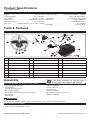
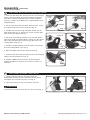
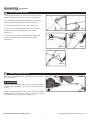
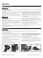
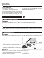
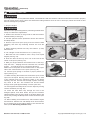
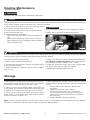
Operator’s Manual
TRIMMER / BRUSH CUTTER
30cc, 2 Cycle MODEL Nos. S-HBR-3017-SBEZ-E
Look inside for:
Safety Definitions
Important Safety Information
Product Specifications
Parts & Features
Assembly
Operation
Routine Maintenance
Storage
Troubleshooting
Technical Service
Warranty
S-HBR-3017-SBEZ
For Occasional Use Only
Page
1
2-4
5
5
5-7
8-11
12
12
13
13
14-19
IMPORTANT:
Thank you for purchasing this Southland™ Trimmer / Brush Cutter.
This manual provides complete instructions for safely operating, and maintaining your Trimmer / Brush Cutter. Read and
save these instructions. Refer to this manual each time before using your Trimmer / Brush Cutter.
Record the following for future reference:
Mfg. Date Code : __________________
Date of Purchase: Attach a copy of your sales receipt.
Consumer Toll Free Number: 1-800-737-2112
Refer to the website for electronic manual and parts book.
www.gardnerinc.com
WARNING
This product contains one or more chemicals known to the State of California to cause cancer and birth defects or other
reproductive harm. Wash hands after handling.
If you have a question or problem...
CALL TOLL FREE: 1-800-737-2112
KEEP THIS MANUAL FOR FUTURE REFERENCE
01/27/2010
Printed in China
A200482
Safety Definitions
• Save all instructions
Safety Warning Symbols:
Indicates Warning.
Keep all by-standers at least 50 ft.
(15 m) away.
Read these instructions carefully.
This equipment can throw small objects
at high speed causing personal injury.
Inspect area where used and remove
all foreign objects.
Always wear eye protection that meets or
exceeds the requirements of ANSI Z87.1.
Wear hearing protection.
Wear breathing protection.
Keep all parts of your body away from
the rotating trimmer lines/ brush cutter
blades.
Wear safety footwear.
Explosive material.
Wear safety gloves.
Extremely hot surface. Do not touch
a hot muffler, gear box or cylinder,
you may get burned. These parts get
extremely hot from operation and
remain hot for a short time after the unit
is turned off.
Be aware of the danger of Blade Thrust
or Kick Back. Blade Thrust and Kick
Back may occur when the spinning
blade contacts an object that it does
not immediately cut.
Control and Operating Symbols:
Choke Control:
Cold Start
Fuel Mixture
40:1
Unleaded Gas: 2 Cycle Oil
Caution: Do Not Use Gas
Mix with More Than 10%
Methanol or Ethanol
Run/Warm Start
Fuel Primer:
Press 6 times.
Fuel Mixture:
40:1
(Unleaded Gas : 2 Cycle Oil)
Ignition Switch:
ON
OFF
The information listed below should be read and understood by the operator. We utilize the symbols below to allow the
reader to recognize important information about their safety.
DANGER
WARNING
CAUTION
Indicates an imminently hazardous situation which, if not avoided, will result in death or serious injury.
Indicates a potentially hazardous situation which, if not avoided, could result in death or serious injury.
Indicates a potentially hazardous situation which, if not avoided, may result in minor or moderate injury.
Questions? Call Toll Free at 1-800-737-2112
1
Copyright © 2010 MAT Engine Technologies, LLC
Important Safety Information
• Save all instructions
Before Operating Trimmer / Brush Cutter
READ AND UNDERSTAND ALL INSTRUCTIONS BEFORE OPERATING Trimmer / Brush Cutter.
WARNING
Read and follow all warnings and safety instructions. Failure to do so can result in serious injury to you or bystanders.
1. Avoid Dangerous Environments
a. Do not operate Trimmer / Brush Cutter while under the influence of alcohol, medications, or drugs.
b. Do not operate Trimmer / Brush Cutter when you are tired.
c. Do not use this Trimmer / Brush Cutter if you are mentally or physically unable to operate safely.
2. Inspect Trimmer / Brush Cutter for damaged parts, and make sure all fasteners and guards are in place and secure.
Replace any damaged parts.
3. The handles must be mounted in accordance with the Operators Manual.
4. Use only 0.080 inch (2 mm) diameter flexible, nonmetallic line with this Trimmer.
DANGER
Never use this Trimmer / Brush Cutter with other accessories not specifically approved for use in this manual. Never use
alternative cutting members such as wire or wire-rope, which can break off and become a dangerous projectile.
5. Dress properly when operating Trimmer / Brush Cutter.
a. Always wear heavy long pants, boots, gloves, and a long-sleeve shirt.
b. Do not wear loose clothing or jewelry that can get caught in the moving parts of the Trimmer / Brush Cutter.
c. Always wear gloves and substantial foot wear when working outside.
d. Always wear protective hair covering to contain long hair.
6. Always wear a face or dust mask if operation is dusty.
7. Always wear eye protection that meets or exceeds the requirements of ANSI Z87.1.
8. Always wear hearing protection which meets or exceeds ANSI standards.
9. Thoroughly inspect the area where the Trimmer / Brush Cutter is to be used and remove all foreign objects.
WARNING
Your equipment can throw small objects at high speed causing personal injury or property damage.
While Operating Trimmer / Brush Cutter
1. Always wear shoulder harness when operating the trimmer / brush cutter. Maintain a firm grip on the handle while
cutting. Keep the blade / string away from your body and below waist level.
2. Stay alert. Use common sense. Watch what you are doing.
3. Do not operate Trimmer / Brush Cutter if it is damaged or not securely and fully assembled.
4. Only well instructed adults should operate Trimmer / Brush Cutter. Never allow children to operate Trimmer / Brush
Cutter.
5. Keep children away. Keep all bystanders at least 50 ft (15 m) away.
6. This Trimmer / Brush Cutter is only intended for trimming, scalping, and mowing. Do not use Trimmer / Brush Cutter
for any job except that for which it is intended. Do not use for edging, pruning or hedge trimming. Severe personal injury
to yourself or others can result.
7. The trimmer line / Blade may be spinning during carburetor adjustments. Make carburetor adjustments with lower
end supported to prevent Trimmer line / Blade from contacting any object.
8. Maintain your balance and proper footing at all times. Do not overreach.
9. Keep rotating trimmer head / Blade below waist level. Keep all parts of your body away from cutting area, the rotating trimmer lines / Blade and hot surfaces.
Questions? Call Toll Free at 1-800-737-2112
2
Copyright © 2010 MAT Engine Technologies, LLC
Important Safety Information
(Continued)
• Save all instructions
While Operating Trimmer / Brush Cutter
10.Hold the unit firmly with both hands.
11.Always keep engine on the right hand side of your body.
12.Always use the Trimmer / Brush Cutter in a sweeping motion from your right to your left. Cutting on left side and
front of the trimmer / blade guard will throw debris away from you.
13.Stay extreme caution when using the blade with this unit. Blade thrust or Kick Back may occur when the spinning
blade contacts an object that it does not immediately cut. A blade thrust can be violent enough to cause the unit and/or
operator to be propelled in any direction, and possibly lose control of the unit. Blade thrust can occur without warning if
the blade snags, stalls or binds. Blade thrust is more likely to occur in areas where it is difficult to see the material being
cut.
14.An improper or dull blade can cause serious personal injury. Blades must be sharp. Discard blades that are bent,
warped, cracked, broken or damaged in any way. Do not sharpen the cutting blade. Sharpening blade can cause the
blade tip to break off while in use, and can result in severe personal injury to you or bystanders.
15.Use only the manufacturer’s replacement blade intended to this Brushcutter. Do not use any other blade. To install
any other brand blade to this brush cutter can result in serious personal injury.
16.Do not force Trimmer / Brush Cutter. It will do the job better and with less likelihood of a risk of injury at the rate for
which it was designed.
17.After turning the unit off, make sure the trimmer line / cutting blade has stopped before the unit is set down.
18.A coasting blade can cause injury while it continues to spin after the engine is stopped or throttle lever is released.
Maintain proper control until the blade has completely stopped rotating.
19.Never cut with the String Trimmer Head or Blade located 30 inch or more above the ground.
DANGER
Never start or run the unit inside a closed room or building; breathing exhaust fumes can kill.
WARNING
Never use the blade or string cut any material over 1/2’ inch diameter. The blade is designed for cutting thicker weeds or
pulpy stalks. Do not use for any other purpose. Never use the blade to cut woody brush.
CAUTION
Prolonged exposure to vibrations through use of gasoline powered hand tools could cause blood vessel or nerve damage in fingers, hands, and joints of people prone to circulation disorders or abnormal swellings. Extensive use in cold
weather has been linked to blood vessel damage in otherwise healthy people. If symptoms occur such as numbness,
pain, loss of strength, change in skin color or texture, or loss of feeling in the fingers, hands, or joints, discontinue the
use of this tool and seek medical attention.
Fuel Safety
1. Mix and pour fuel outdoors WHERE THERE ARE NO SPARKS OR FLAMES.
2. Use a container approved for gasoline.
3. Do not smoke or allow smoking near fuel or the Trimmer / Brush Cutter.
4. Avoid spilling fuel or oil. Wipe up all fuel spills.
5. Move at least 10 feet (3 meters) away from fueling site before starting engine.
6. Stop engine and allow to cool before removing fuel cap. Remove fuel cap slowly.
Questions? Call Toll Free at 1-800-737-2112
3
Copyright © 2010 MAT Engine Technologies, LLC
Important Safety Information
(Continued)
• Save all instructions
Maintenance & Storage of Trimmer / Brush Cutter
1. Disconnect the spark plug before performing maintenance.
2. Maintain Trimmer / Brush Cutter with care. Inspect Trimmer / Brush Cutter periodically. If Trimmer / Brush Cutter is not
working properly or damaged, have it repaired by a qualified service center.
3. Check for misalignment of moving parts, binding of moving parts, broken parts, mounting, and any other condition that
may affect its operation.
4. Keep guards in place and in working order.
5. A guard or other part that is damaged should be properly repaired or replaced by a qualified service center.
6. Use only genuine Southland™ replacement parts and accessories. Use of any non-Southland™ parts or accessories
could lead to injury, damage to the unit, and will void your warranty.
7. Do not remove or modify any parts. Removing or modifying parts could lead to injury, damage the Trimmer / Brush
Cutter and will void the warranty.
8. Keep handles dry, clean, and free from oil and grease.
9. Allow engine to cool and empty the fuel tank before storing or transporting in vehicle. Use up remaining fuel in the
carburetor by starting the engine and letting it run until it stops.
10. When not in use, store Trimmer / Brush Cutter indoors in a dry location. Store Trimmer / Brush Cutter above the reach
of children or in a locked area out of the reach of children.
11. Store unit and fuel in area where fuel vapors cannot reach sparks or open flames from water heaters, electric motors
or switches, furnaces, etc.
Questions? Call Toll Free at 1-800-737-2112
4
Copyright © 2010 MAT Engine Technologies, LLC
Product Specifications
• Save all instructions
Engine . . . . . . . . . . . . . . . . . . . . . . . . . . . . . . 30 cc, 2 cycle 2-Cycle Oil Type . . . . . . . 2-Cycle Oil that meets or exceeds
Cutting Diameter . . . . . . . . . . . . . . . . . . . . 17 in. (432 mm) . . . . . . . . . . . . . . . . . . . . . . . . . . . JASO – FC Specifications
Line Diameter . . . . . . . . . . . . . . . . . . . . . . 0.080 in. (2 mm) Fuel Mixture . . . . . . . . . . . . . . . . 40:1 (Gasoline: 2-Cycle Oil)
Spool Type . . . . . . . . . . . . . . . . . . . Bump-Feed, Twin-Line Spark Plug . . . . . . . . . . . . . . . . . . . . . . . . . . NGK - BPMR7A
Fuel Tank Capacity . . . . . . . . . . . . . . . . . . . 20 oz (600 ml) . . . . . . . . . . . . . . . . . . . . . . . . . . . . . . . CHAMPION - CJ7Y
Fuel Type . . . . . . . . Unleaded Gasoline – 87 Octane or higher . . . . . . . . . . . . . . . . . . . . . . . . . . . . . . . . . . . . or equivalent
Net Weight . . . . . . . . . . . . . . . . . . . . . . . . . . 15.2 lbs (6.9 kg)
Parts & Features
7
21
17
23
6
22
19
18
3
8
5
16
11
12
20
4
1
15
2
9
10
14
13
1.
Trimmer Head Assembly
9.
Choke
17.
Shaft
2.
Bump Knob
10.
Fuel Primer Bulb
18.
Gear Head
3.
Trimmer Guard
11.
Spark Plug
19.
Blade Guard
4.
Trimmer Line Knife
12.
Muffler
20.
Shoulder Harness
5.
Cow Bar Handle
13.
Fuel Tank
21.
Cutting Blade
6.
Throttle Lever
14.
Air Filter Cover
22.
Joystick Throttle Control
7.
On/Off Ignition Switch
15.
Safety Lever
23.
Throttle Lock
8.
Recoil Starter Handle
16.
Spool Housing
Assembly
If you need assistance or find any parts
missing, CALL TOLL FREE: 1-800–737-2112
Parts Included With The Trimmer / Brush Cutter
• Cow Bar Handle with bolts
• Cutting Blade
• Trimmer Head Assembly
• Brush Cutter Guard
• Expandable Trimmer Guard with bolt and nut
• Handle Grip
• M10 Wrench
•
•
•
•
•
•
Spark Plug Wrench
Hex Key Wrench
Star Drive Key
Shoulder Harness
40:1 2-Cycle Engine Oil (3.2 fl. oz.)
Operator’s Manual
WARNING
Do not operate Trimmer / Brush Cutter if it is damaged or not securely and fully assembled.
Tools Needed For Assembly
• 10 mm wrench or adjustable wrench.
Questions? Call Toll Free at 1-800-737-2112
5
Copyright © 2010 MAT Engine Technologies, LLC
Assembly
(Continued)
• Save all instructions
A
To Assemble Brush Cutter Guard and Cutting Blade:
1.Insert the Star Drive Key through the slot in the Flanged
Spacer and Gear Head, and use the Spark Plug Wrench
provided to remove the Blade Nut by turning clockwise.
(see Fig. 1) Remove the Blade Nut, Cupped Washer, and
Flanged Spacer.
FLANGED
SPACER
CUPPED
WASHER
2.Use the Star Drive Key provided, Remove the 3 screws
from Gear Head at the end of Shaft (see Fig. 2).
LOOSENING
Fig. 2
Fig. 1
3.Install the 3 screws through the Blade Guard into the
Gear Head (see Fig. 3). Tighten the screws securely with
M10 wrench and Start Drive Key.
RAISED CENTER
ALIGN HOLES
4.Put back on the Flanged Spacer over the Gear Head
shaft, and install the Cutting Blade, making sure the raised
hub of the Flanged Spacer goes through the hole in the
Cutting Blade. (see Fig. 4)
5.Install the Cupped Washer with the raised center away
from the Cutting Blade. (see Fig. 4)
Fig. 3
ALIGN
Fig. 4
6.Place the Blade Nut onto the Gear Head shaft.
7.Insert the Star Drive Key through the slot in the Flanged
Spacer and Gear Head (see Fig. 5).
8.Install the Blade Nut by turning it counterclockwise.
Tighten the blade nut securely and torque to 190 lbs. in.
minimum.
B
TIGHTENING
Fig. 5
To Assemble Expandable Trimmer Guard:
1. Use the Star Key Wrench provided, attach the
Expandable Trimmer Guard to the Brush Cutter Guard,
and tighten the 3 screws securely. (see Fig. 6)
LINE KNIFE
2. Remove protective cover from trimmer line knife.
CAUTION
The trimmer line knife is sharp and can cut you (see Fig. 7).
Questions? Call Toll Free at 1-800-737-2112
Fig. 6
6
Fig. 7
Copyright © 2010 MAT Engine Technologies, LLC
Assembly
(Continued)
• Save all instructions
C
To Install Cow Bar Handle:
1. Attach the Handle to the Shaft, and use the Hex Key
Wrench to tighten the 2 bolts in the front. (See Fig. 8)
2. To adjust the Handle to desired position, tighten the 2
bolts in the back until handle is secure. (see Fig. 9)
3. Put on the Handle Grip on the left. (see Fig. 10)
4. Place the Joystick Control to right of the Handle by
installing the bolt through the hole in the handle.
(see Fig. 11)
5. Use the 2 clips on the Throttle Cable to adjust and
attach the Throttle Cable to the Shaft and Handle.
(see Fig.12)
Fig. 8
Fig. 9
Fig. 10
Fig. 11
PUSH DOWN
CLIPS
Fig. 12
D
To Attach Shoulder Harness:
This unit is equipped with an adjustable shoulder harness
for your comfort.
WARNING
Always wear shoulder harness when operating the trimmer
/ brush cutter. Maintain a firm grip on the handle while
cutting.
Fig. 13
Attach shoulder harness to clip on the shaft, and adjust
harness length so that the weight of the unit can be
comfortably supported during use (see Fig. 13).
Questions? Call Toll Free at 1-800-737-2112
7
Copyright © 2010 MAT Engine Technologies, LLC
Operation
• Save all instructions
A
Before Starting Engine:
Mixing Fuel / 2-Cycle Oil
WARNING
Do not smoke or allow smoking near fuel or the Trimmer / Brush Cutter. Mix and pour fuel outdoors WHERE THERE ARE
NO SPARKS OR FLAMES.
The 2-cycle engine on your Trimmer / Brush Cutter requires
that fuel and
2-cycle engine oil be pre-mixed before adding to the Trimmer
/ Brush Cutter’s fuel tank. To mix the fuel/ 2-cycle oil:
5. Follow instructions on 2-cycle oil container for mixing fuel.
Mix gasoline and 2-cycle oil at a ratio of 40:1. A mixture
with a 40:1 ratio is obtained by mixing 1 gallon (4 liters)
of gasoline with 3.2 ounces of oil (95 ml). After adding oil to
1. Use fresh unleaded gasoline with an octane rating of gasoline, shake container momentarily to ensure proper mixing.
87 or higher. Do not use gasoline containing ethanol or 6. Mix only enough fuel for your immediate needs. Do not
methanol.
store pre-mixed fuel.
7. Stop engine and allow to cool before refueling.
CAUTION
Use of gasoline containing ethanol or methanol can damage 8. To fill the Trimmer / Brush Cutter’s fuel tank with the
gasoline/ oil mixture, place the Trimmer / Brush Cutter
Trimmer / Brush Cutter.
upright on the ground or on a sturdy bench and wipe and
2. Always use 2-cycle oil that meets or exceeds JASO – FC any debris from around the fuel cap.
specifications and is intended for mixing at a fuel/oil ratio of 40:1.
9. Remove fuel cap slowly and use a funnel to pour the
3. Do not use automotive or 2-cycle marine outboard oil. mixture into the tank, and replace the fuel cap.
These will damage your Trimmer / Brush Cutter’s engine and
10. Avoid spilling fuel or oil. Wipe up all fuel spills.
void the warranty.
4. Always mix the gasoline and 2-cycle oil in a container 11. Move at least 10 feet (3 meters) away from fueling site
approved for gasoline. Never mix fuel directly in the Trimmer before starting engine.
/ Brush Cutter’s fuel tank.
B
Starting Engine:
WARNING
Keep all parts of your body away from cutting area, the rotating Trimmer / Brush Cutter lines and hot surfaces.
Cold Starting The Engine
DO NOT squeeze the throttle lever until engine starts and runs.
Note: when the weather gets cold, please allow the
engine to warm up at idle for longer period of time,
before engaging to RUN/WARM START position.
1. Place the Trimmer / Brush Cutter on a flat surface.
2. Move the Ignition Switch to the “ON” position (see Fig. 14).
Warm Starting The Engine
1. Place the Trimmer / Brush Cutter on a flat surface.
3. Move the Choke Lever downwards to the “COLD START”
position (see Fig. 15).
2. Move the Ignition Switch to the “ON” position (see Fig. 14).
4. Press the Primer Bulb slowly 6 times (see Fig. 16).
3. With the choke lever in “Run/Warm Start” position,
squeeze the throttle lever, pull the Recoil Starter Handle
sharply until the engine starts and runs.
5. Pull the Recoil Starter Handle sharply until the engine
starts and runs (see Fig. 17).
6. After engine starts and runs for 10-15 seconds, move
choke lever to “Run/Warm Start” position.
COLD START
ON
PRIMER BULB
RUN/WARM START
Fig. 14
Questions? Call Toll Free at 1-800-737-2112
Fig. 16
Fig. 15
8
Fig. 17
Copyright © 2010 MAT Engine Technologies, LLC
Operation
(Continued)
• Save all instructions
B
Starting Engine:
Starting A Flooded Engine
4. If the engine still does not start, allow the unit to sit for
about 30 minutes, and repeat step 1-3.
1. Place the unit on a flat surface.
2. Move the Ignition Switch to the “ON” position.
3. With the choke lever in “Run/Warm Start” position,
squeeze and hold the Throttle Lever fully depressed and pull
the starter handle repeatedly until engine starts and runs.
This could require pulling the starter handle many times,
depending on how badly the unit is flooded.
If the unit still doesn’t start, refer to the
TROUBLESHOOTING section of this manual or:
C
If you need assistance or have any questions,
CALL TOLL FREE: 1-800–737-2112
Stopping The Trimmer / Brush Cutter:
CAUTION
The trimmer line/ cutting blade will continue to rotate for a few seconds after the engine has stopped.
1. Release the Throttle Lever and allow the engine to idle for a few moments.
2. Move the Ignition Switch to the “OFF” position.
D
Engine Break-in Period:
During the first ten (10) hours of use, use the slowest engine speed which allows for effective cutting and avoid operation
at high engine speeds for extended periods of time.
This will maximize the life and performance of engine of your unit. Maximum power will be achieved after the first ten (10)
hours of engine operation.
E
Operating the Brush Cutter:
WARNING
Always wear shoulder harness when operating the trimmer / brush cutter. Maintain a firm grip on the handle while cutting.
1. Wear shoulder harness before starts the engine.
(see Fig. 18)
2. Follow the instruction of “Starting Engine” on page 8.
3. After the engine starts, attach shoulder harness to clip
on the shaft, and adjust harness length so that the weight
of the unit can be comfortably supported during use
(see Fig. 19)
Fig. 18
4. Hold the brush cutter with you both hands on the cow
bar handle. Keep a firm grip with both hands while in use.
Maintain footing and balance at all time.
5. Squeeze and hold both the throttle and safety levers to
start the operation.
Fig. 19
THROTTLE LOCK
The throttle lock can be used to operate the unit without holding the throttle lever.
To engage the throttle lock:
1. With the throttle and safety levers squeezed, press the
throttle lock to lock the throttle setting.
Questions? Call Toll Free at 1-800-737-2112
To disengage the throttle lock:
1. Squeeze the throttle and safety levers, and the throttle
lock will be released.
9
Copyright © 2010 MAT Engine Technologies, LLC
Operation
(Continued)
• Save all instructions
F
Advancing Trimmer Line:
The Trimmer is most effective when the Trimmer line is
advanced to full cutting width. To advance the Trimmer line:
1. Hold bottom of Trimmer Head parallel to grassy surface
(see Figure 20).
Fig. 20
2. With the engine at full throttle, firmly tap or bump the
Trimmer Head on the ground.
3. Trimmer line will be advanced with each tap or bump.
4. Continue to advance Trimmer line until you reach full
cutting width (i.e. when the Trimmer line is cut by the
Trimmer Line Knife).
G
Techniques / Applications:
WARNING
Thoroughly inspect the area where the Trimmer is to be used and remove all foreign objects. Your equipment can throw
small objects at high speed causing personal injury or property damage.
Your Trimmer is most effective when using the tips of the Trimmer line for trimming grass and other vegetation. Do not force
the Trimmer line into grass or vegetation faster than Trimmer’s cutting speed permits.
Forcing the Trimmer will cause your Trimmer to be less effective, and will cause excessive wear on the Trimmer line.
To avoid damaging trees, shrubs and fences:
1. Maintain Trimmer line to the full cutting width by advancing 3. Use the slowest engine speed that will permit effective
Trimmer / Brush Cutter line as necessary.
cutting. This will provide the greatest control of the trimming
2. Move the tips of the Trimmer line slowly into the grass or line, reduce engine noise and vibration, and extend Trimmer
line life.
vegetation to be trimmed.
Use a sweeping motion from right to left (see Fig. 21a) to
move the Trimmer line into the grass or vegetation to be cut.
By using the trimming line on the left side and front of the
Trimmer Guard, debris will be thrown away from you
(see Fig. 21b).
Fig. 21a
SWEEP RIGHT
TO LEFT
Trimming
Holding the Trimmer Head approximately 3 inches (76 mm)
above the ground – with the Trimmer line angled down
towards the grass or vegetation to be trimmed, move the
Trimmer Head in a sweeping motion from right to left into
the grass or vegetation (see Fig. 22).
Fig. 21b
SAFE CUTTING
ZONE
Fig. 22
Scalping
Scalping is a technique similar to Trimming, but clears
all vegetation to the ground. Holding the Trimmer Head
approximately 3 inches (76 mm) above the ground –
with the Trimmer line angled down towards the grass or
vegetation to be trimmed. Allow the Trimmer line to strike
the ground where scalping is desired (see Fig. 23).
3” (76 mm)
Fig. 23
3” (76 mm)
Mowing
The Trimmer is effective in mowing areas your lawn mower cannot easily reach. Holding the Trimmer Head parallel to the
ground, move the Trimmer Head in sweeping motions from right to left. Avoid the Trimmer Head contacting the ground,
this may scalp the grass and damage the unit.
Questions? Call Toll Free at 1-800-737-2112
10
Copyright © 2010 MAT Engine Technologies, LLC
Operation
(Continued)
• Save all instructions
H
Replacing Trimmer Line:
WARNING
Use only 0.080 inch (2 mm) diameter flexible, nonmetallic line with this Trimmer. Other line sizes will not function properly
and can cause serious injury. Never use alternative cutting members such as wire or wire-rope, which can break off and
become a dangerous projectile.
1. Stop the engine.
WARNING
Disconnect the Spark Plug before performing maintenance
except for carburetor adjustments.
2. Position the Trimmer on the ground so that the Trimmer
Head Assembly is facing up.
3. Use the spanner wrench provided to loosen and remove
the Bump Knob.
Fig. 25
Fig. 24
4. Remove spool and spool spring from the Trimmer Head
Assembly, and clear any remaining Trimmer line from the
spool.
SPOOL SPRING
WIND LINE IN THIS DIRECTION
5. When replacing Trimmer line only use 0.080 in. (2 mm)
diameter line.
6. Cut a length of new Trimmer line 15 ft. (4.6 m) long.
7. Bend the line in the middle to form a loop of two equal
lengths (see Fig. 24).
Fig. 26
8. Hook the bend of the loop onto one of the slots in the
center of the spool (see Fig. 25).
Fig. 27
TIGHTENING
9. With your finger between the Trimmer lines of the loop,
wrap the lines – keeping the lines taut with firm, constant
tension - around the spool in a clockwise direction.
Make sure to keep each of the Trimmer lines on the proper
side of the center divider on the spool (see Fig. 26).
10. Confirm spool spring is secured in proper position on
spool (see Fig. 27).
Fig. 28
11. While securing the Trimmer line around the spool, insert
spool into the Spool Housing and insert the end of each
of the Trimmer lines into opposing eyelets in the Spool
Housing. Pull the Trimmer line through eyelets removing
any slack in the line. The Trimmer line should extend
through each eyelet approximately 4 inches (102 mm).
12. Hand tighten the Bump Knob onto the Spool by turning
counter-clockwise (see Fig. 28).
13. Insert the Star Drive Key through the slot in the
Flanged Spacer and Gear Head, and put the Trimmer
Head Assembly onto the drive shaft of the Gear Head, and
secure it by turning the Bump Knob counter-clockwise (see
Fig. 28).
14. After installing new Trimmer line, start Trimmer engine
and advance Trimmer line with Bump Knob until Trimmer
line is trimmed at its full cutting width by the Trimmer line
knife (see F. Advancing Trimmer Line).
Questions? Call Toll Free at 1-800-737-2112
11
Copyright © 2010 MAT Engine Technologies, LLC
Routine Maintenance
• Save all instructions
WARNING
Disconnect the spark plug before performing maintenance.
A
Air Filter:
Accumulated debris and dust in the air filter will reduce engine performance, increase fuel consumption and increases the
risk of engine damage. Clean the air filter every 5 hours of operation.
1. Before removing Air Filter Cover, brush away any loose
dirt or debris on and around the filter cover.
WARNING
Never clean filter in gasoline or other flammable solvents.
2. To remove Air Filter Cover, press on the side tab and
pull cover out (see Fig. 29).
4. Add a drop of thin oil to the filter and replace it.
3. Remove and clean foam filter.
• Light surface dust can readily be removed by tapping the filter.
• Heavy deposits should be washed out in soap and water. Squeeze out any remaining water and allow the filter to completely dry.
PULL OUT
Fig. 29
B
Spark Plug:
Inspect the spark plug after every 10-15 hours of use; adjust spark plug gap and replace spark plug as necessary. Replace
spark plug every year to maintain engine performance and easy starting.
To inspect or replace the Spark Plug:
1. Remove the insulated spark plug boot.
4. Replace any worn plug with a recommended replacement
(see PRODUCT SPECIFICATIONS. Clean and adjust the
spark plug gap to 0.024 – 0.028 in. (0.6 - 0.7mm).
2. Use the spark plug wrench to remove the Spark Plug, by
5. Install the Spark Plug finger tight in the cylinder head,
turning counter-clockwise.
then tighten firmly with the spark plug wrench.
3. Clean and adjust the spark plug gap to 0.024 – 0.028 in.
6. Replace the insulated spark plug boot.
(0.6 - 0.7mm).
Storage
1. Allow engine to cool and empty the fuel tank before storing or 4. When preparing the Trimmer / Brush Cutter for storage
transporting in vehicle. Use up remaining fuel in the carburetor or when Trimmer / Brush Cutter will not be used for 30 days
by starting the engine and letting it run until it stops.
or more:
a. Inspect and clean the Trimmer / Brush Cutter 2. When not in use, store Trimmer / Brush Cutter indoors in
thoroughly.
a dry location. Store Trimmer / Brush Cutter above the reach
b. Lightly oil all external metal surfaces.
of children or in a locked area out of the reach of children.
c. Remove the spark plug, place a few drops of 3. Store unit and fuel in area where fuel vapors cannot
2-cycle engine oil into the cylinder. Pull the recoil reach sparks or open flames from water heaters, electric
starter several times to distribute the oil. Replace motors or switches, furnaces, etc.
the spark plug.
d. Inspect and clean air filter as required.
NOTE: To prevent fuel gum deposits in the carburetor and fuel system, it is acceptable to use fuel stabilizer. Follow the stabilizer
manufacturer’s instructions. Run the engine at least 5 minutes after adding stabilizer.
Questions? Call Toll Free at 1-800-737-2112
12
Copyright © 2010 MAT Engine Technologies, LLC
Troubleshooting
• Save all instructions
PROBLEM
POSSIBLE CAUSE(S)
Engine will not start.
1. Ignition Switch in the “OFF” position. 1. Move ignition switch to the ON position.
2. Engine flooded.
2. See Starting a Flooded Engine in
OPERATION section.
3. Fuel Tank empty.
3. Fill tank with correct fuel mixture.
4. Spark Plug not firing.
4. Replace Spark Plug.
5. Fuel not reaching carburetor.
5. Check for kinked or split fuel line; repair
or replace.
6. Carburetor requires adjustment.
6. Contact a qualified service center.
Engine will not accelerate, lacks
power or stalls.
Engine smokes excessively.
Engine runs hot.
Engine will not idle properly.
SOLLUTION(S)
1. Grass wrapped around Trimmer /
Brush Cutter Head.
2. Air filter dirty.
3. Spark plug fouled.
4. Carburetor requires adjustment.
5. Carbon build-up on muffler outlet
screen.
6. Compression low.
1. Fuel mixture incorrect.
2. Air filter dirty.
3. Carburetor requires adjustment.
1. Fuel mixture incorrect.
2. Spark Plug incorrect.
3. Carburetor requires adjustment.
4. Carbon build-up on muffler outlet
screen.
1. Carburetor requires adjustment.
2. Crankshaft seals worn.
3. Compression low.
1. Clear debris and grass from Trimmer / Brush
Cutter Head.
2. Clean air filter.
3. Clean or replace plug
4. Contact a qualified service center.
5. Contact a qualified service center.
6. Contact a qualified service center.
1. Empty Fuel Tank and refill with correct fuel
mixture.
2. Clean or replace air filter.
3. Contact a qualified service center.
1. See Mixing Fuel / 2-Cycle Oil in
OPERATION section.
2. Replace with correct Spark Plug.
3. Contact a qualified service center.
4. Contact a qualified service center.
1. Contact a qualified service center.
2. Contact a qualified service center.
3. Contact a qualified service center.
Technical Service
You may have further questions about assembling, operating, or maintaining this Trimmer / Brush Cutter. If so, you can
contact our Technical Service Department at 1-800-737-2112 (English only).
You may also write to:
METL Corporate Office - CORRESPONDENCE ONLY
ATTN: Technical Service – METL
6700 Wildlife Way
Long Grove, IL 60047
When contacting the Technical Service Department, have
ready:
• Your Name
• Your Address
• Your Phone Number
Questions? Call Toll Free at 1-800-737-2112
If you need assistance or have any questions,
CALL TOLL FREE: 1-800–737-2112
• Model Number of Product
• Date of Purchase (include copy of receipt for written requests)
13
Copyright © 2010 MAT Engine Technologies, LLC
Warranty
• Save all instructions
A
Southland™ Trimmer / Brush Cutter Limited Warranty
Always specify model number when contacting the factory.
We reserve the right to amend these specifications at any time without notice. The only warranty applicable is our standard
written warranty. We make no other warranty, expressed or implied. MAT Engine Technologies, LLC warrants this Trimmer /
Brush Cutter and any parts thereof, to be free from defects in material and workmanship for two years (90 days for reconditioned
unit) from the date of first purchase from an authorized dealer, provided that the product has been properly maintained and
operated in accordance with all applicable instructions. This warranty is extended only to the original retail purchaser. The bill
of sales or proof of purchase must be presented at the time a claim is made under this warranty. This warranty does not cover
commercial, industrial, or rental usage, nor does it apply to parts that are not in original condition because of normal wear and
tear, or parts that fail or become damaged as a result of misuse, accident, lack of proper maintenance, tampering, or alteration.
Travel, handling, transportation, and incidental costs associated with warranty repairs are not reimbursable under this warranty
and are the responsibility of the owner. To the full extent allowed by the law of the jurisdiction that governs the sale of the product,
this express warranty excludes any and all other expressed warranties and limits the duration of any and all implied warranties,
including warranties of merchantability and fitness for a particular purpose to two years from the date of first purchase, and MAT
Engine Technologies, LLC’s liability is hereby limited to the purchase price of the product and MAT Engine Technologies,
LLC shall not be liable for any other damages whatsoever including indirect, incidental, or consequential damages. Some states
do not allow limitation of how long an implied warranty lasts or an exclusion or limitation of incidental or consequential damages,
so the above limitation of damages may not apply to you. This warranty provides the original purchaser with specific rights.
For information regarding those rights, please consult the applicable state laws.
METL Corporate Office - CORRESPONDENCE ONLY
ATTN: Technical Service – METL
6700 Wildlife Way
Long Grove, IL 60047
B
Federal and California Emissions Control Warranty Statement
This MAT Engine Technologies, LLC (METL) outdoor power equipment engine complies with the emissions regulations of:
Southland™ Model No.
Regulatory Agency
S-HBR-3017-SBEZ-E
United States Environmental Protection Agency (“U.S. EPA”)
S-HBR-3017-SBEZ
State of California
To the extent there is any conflict between this Emissions Control Warranty and the METL Limited Warranty, this Emissions Control
Warranty shall apply except where the METL Limited Warranty may provide a longer warranty period.
Please read your warranty rights and obligations carefully. Some sections of the warranty may not apply to the specific
model you purchased. Unless specifically noted otherwise, the terms below shall apply to all Southland™ products
covered within this manual.
YOUR WARRANTY RIGHTS AND OBLIGATIONS
State of California (Applies only to Model No. S-HBR-3017-SBEZ):
The California Air Resources Board and MAT Engine Technologies, LLC (METL) are pleased to explain the emissions
control system warranty on your 2010 small off-road engine (SORE). In California, new SOREs must be designed, built
and equipped to meet the State’s stringent anti-smog standards. METL must warrant the emissions control system on
your SOREs for the periods of time listed below provided there has been no abuse, neglect or improper maintenance of
your SOREs.
Questions? Call Toll Free at 1-800-737-2112
14
Copyright © 2010 MAT Engine Technologies, LLC
Warranty
(Continued)
• Save all instructions
Other U.S States / Territories:
In other areas of the Unites States, your outdoor power equipment engine must be designed, built and equipped so as
to conform at the time of sale to U.S. EPA emissions standards for small off-road spark ignition engines at or below 19
kilowatts.
All of the United States:
Your emission control system may include parts such as the carburetor or fuel-injection system, fuel lines, the ignition
system, and catalytic converter. Also included may be hoses, belts, clamps, connectors and other emission-related
assemblies.
Where a warrantable condition exists, METL will repair your small off-road engine at no cost to you including diagnosis,
parts and labor.
Manufacturer’s Warranty Coverage:
The emissions control system is warranted for two years. If any emissions-related part on your engine is defective, the part
will be repaired or replaced by METL.
Owner’s Warranty Responsibilities:
• As the SORE owner, you are responsible for the performance of the required maintenance listed in your owner’s manual.
METL recommends that you retain all receipts covering maintenance on your SORE, but METL can not deny warranty
solely for the lack of receipts or for your failure to ensure the performance of all scheduled maintenance.
• As the SORE owner, you should however be aware that METL may deny your warranty coverage if your SORE or a part
has failed due to abuse, neglect, improper maintenance or unapproved modifications.
• You are responsible for presenting your SORE to a distribution center or service center authorized by METL as soon as
the problem exists. The warranty repairs should be completed in a reasonable amount of time, not to exceed 30 days.
If you have any questions regarding your warranty
coverage, you should contact METL customer service:
Questions? Call Toll Free at 1-800-737-2112
If you need assistance or have any questions,
CALL TOLL FREE: 1-800–737-2112
15
Copyright © 2010 MAT Engine Technologies, LLC
Warranty
(Continued)
• Save all instructions
Defects Warranty Coverage:
METL warrants to the original purchaser and each subsequent purchaser that the small off-road engine (SORE) (1) has
been designed, built and equipped so as to conform with all applicable regulations; and (2) is free from defects in materials
and workmanship that cause the failure of a warranted part to conform with those regulations as may be applicable to the
terms and conditions stated below.
(a) The warranty period begins on the date the engine is first purchased. The warranty period is two years.
(b) Subject to certain conditions and exclusions as stated below, the warranty on emissions related parts is as follows:
(1) Any warranted part that is not scheduled for replacement as required maintenance in your Operator’s Manual is warranted for the warranty period stated above. If the part fails during the period of warranty coverage, the part will be repaired or replaced by METL according to Subsection (4) below. Any such part repaired or replaced under warranty will be warranted for the remainder of the period.
(2) Any warranted part that is scheduled only for regular inspection in your Operator’s Manual is warranted for the warranty period stated above. Any such part repaired or replaced under warranty will be warranted for the remaining warranty period.
(3) Any warranted part that is scheduled for replacement as required maintenance in your Operator’s Manual is warranted for the period of time before the first scheduled replacement date for that part. If the part fails before the
first scheduled replacement, the part will be repaired or replaced by METL according to Subsection (4) below. Any such part repaired or replaced under warranty will be warranted for the remainder of the period prior to the first scheduled replacement point for the part.
(4) Repair or replacement of any warranted part under the warranty provisions herein must be performed at a warranty station at no charge to the owner.
(5) Notwithstanding the provisions herein, warranty services or repair will be provided at all of our distribution centers that are franchised to service the subject engines.
(6) The engine owner must not be charged for diagnostic labor that leads to the determination that a warranted part is in fact defective, provided that such diagnostic work is performed at a warranty station.
(7) METL is liable for damages to other engine components proximately caused by a failure under warranty of any warranted part.
(8) Throughout the engine warranty period stated above, METL will maintain a supply of warranted parts sufficient to meet the expected demand for such parts.
(9) Any replacement part may be used in the performance of any warranty maintenance or repairs and must be provided without charge to the owner. Such use will not reduce the warranty obligations of METL.
(10) Add-on or modified parts that are not exempted by the Air Resources Board may not be used. The use of
any non-exempted add-on or modified parts by the original or subsequent purchaser will be grounds for disallowing a warranty claims. METL will not be liable to warrant failures of warranted parts caused by the use of a non-
exempted add-on or modified part.
(11) The manufacturer issuing the warranty shall provide any documents that describe that warranty procedures or policies within five working days or requested by the Air Resources Board.
Questions? Call Toll Free at 1-800-737-2112
16
Copyright © 2010 MAT Engine Technologies, LLC
Warranty
(Continued)
• Save all instructions
Emission Warranty Parts List:
The repair or replacement of any warranted part otherwise eligible for warranty coverage may be excluded from such
warranty coverage if METL demonstrates that the engine has been abused, neglected, or improperly maintained, and that
such abuse, neglect, or improper maintenance was the direct cause of the need for repair or replacement of the part. That
notwithstanding, any adjustment of a component that has a factory installed, and properly operating, adjustment limiting
device is still eligible for warranty coverage. The following emissions warranty parts list is covered.
(1) Fuel Metering System:
(a) Gasoline carburetor assembly and its internal components (if so equipped)
(b) Fuel filter (if so equipped)
(c) Carburetor gaskets
(d) Fuel pump (if so equipped)
(2) Air Induction System including:
(a) Intake pipe/manifold
(b) Air cleaner
(4) Catalytic Muffler Assembly (if so equipped) including:
(a) Muffler gasket
(b) Exhaust manifold
(5) Crankcase Breather Assembly including:
(a) Breather connection tube.
(6) Miscellaneous items Used in Above Systems including:
(a) Switches
(b) Hoses, belts, connectors, and assemblies.
(3) Ignition System including:
(a) Spark plug
(b) Ignition module/coil
Questions? Call Toll Free at 1-800-737-2112
17
Copyright © 2010 MAT Engine Technologies, LLC
Warranty
(Continued)
• Save all instructions
C
California Evaporative Emission Control Warranty Statement
YOUR WARRANTY RIGHTS AND OBLIGATIONS
Applies only to Model No. S-HBR-3017-SBEZ:
The California Air Resources Board and METL are pleased to explain the evaporative emission control system’s warranty
on your 2010 model year small off-road engine (SORE). In California, new SOREs must be designed, built and equipped
to meet the State’s stringent anti-smog standards. METL must warrant the evaporative emission control system on your
SOREs for the period of time listed below provided there has been no abuse, neglect or improper maintenance of your
SOREs.
Your evaporative emission control system may include parts such as: carburetors, fuel tanks, fuel lines, fuel caps, valves,
canisters, filters, vapor hoses, clamps, connectors, and other associated components.
Manufacturer’s Warranty Coverage:
This evaporative emission control system is warranted for two years. If any evaporative emission-related part on your
equipment is defective, the part will be repaired or replaced by METL.
Owner’s Warranty Responsibilities:
• As the SORE owner, you are responsible for performance of the required maintenance listed in your owner’s manual.
METL recommends that you retain all receipts covering maintenance on your SOREs, but METL can not deny warranty
solely for the lack of receipts.
• As the SORE owner, you should however be aware that METL may deny you warranty coverage if your SOREs or a part
have failed due to abuse, neglect, or improper maintenance or unapproved modifications.
• You are responsible for presenting your SOREs to distribution center or service center authorized by METL as soon as
the problem exists. The warranty repairs should be completed in a reasonable amount of time, not to exceed 30 days.
If you have any questions regarding your warranty
coverage, you should contact METL customer service:
Questions? Call Toll Free at 1-800-737-2112
If you need assistance or have any questions,
CALL TOLL FREE: 1-800–737-2112
18
Copyright © 2010 MAT Engine Technologies, LLC
Warranty
(Continued)
• Save all instructions
Defects Warranty Coverage:
(a) The warranty period begins on the date the engine is purchased.
(b) General Evaporative Emissions Warranty Coverage. The engine must be warranted to the ultimate purchaser and
any subsequent owner that the evaporative emission control system when installed was:
(1) Designed, built, and equipped so as to conform with all applicable regulations; and
(2) Free from defects in materials and workmanship that causes the failure of a warranted part for a period of two years.
(c) The warranty on evaporative emissions-related parts will be interpreted as follows:
(1) Any warranted part that is not scheduled for replacement as required maintenance in the written instructions must be warranted for the warranty period defined in subsection (b) (2).
If any such part fails during the period of warrantycoverage, it must be repaired or replaced by METL issuing the warranty. Any such part repaired or replaced under the warranty must be warranted for a time not less than the remaining
warranty period.
(2) Any warranted part that is scheduled only for regular inspection in the written instructions must be warranted for the warranty period defined in subsection (b) (2). A statement in such written instructions to the effect of “repair or replace as necessary” will not reduce the period of warranty coverage. Any such part repaired or replaced under warranty must be warranted for a time not less than the remaining warranty period.
(3) Any warranted part that is scheduled for replacement as required maintenance in the written instructions must be warranted for the period of time prior to the first scheduled replacement point for that part. If the part fails prior to the first scheduled replacement, the part must be repaired or replaced by METL Any such part repaired or replaced under
warranty must be warranted for a time not less than the remainder of the period prior to the first scheduled replacement point for the part.
(4) Repair or replacement of any warranted part under the warranty provisions of this article must be performed at no charge to the owner at a warranty station.
(5) Notwithstanding the provisions of subsection (4) above, warranty services or repairs must be provided at distribution centers that are franchised to service the subject engines or equipment.
(6) The owner must not be charged for diagnostic labor that leads to the determination that a warranted part is in fact defective, provided that such diagnostic work is performed at a warranty station.
(7) Throughout the evaporative emission control system’s warranty period set out in subsection (b) (2), METL issuing the warranty must maintain a supply of warranted parts sufficient to meet the expected demand for such parts.
(8) Manufacturer approved replacement parts must be used in the performance of any warranty maintenance or repairs and must be provided without charge to the owner. Such use will not reduce the warranty obligations of the manufacturer issuing the warranty.
(9) The use of any add-on or modified parts will be grounds for disallowing a warranty claim made in accordance with this article. The manufacturer issuing the warranty will not be liable under this Article to warrant failures of warranted parts caused by the use of an add-on or modified part.
(10) METL issuing the warranty shall provide any documents that describe the warranty procedures or policies within five working days of request by the Executive Officer.
Evaporative Emission Warranty Parts List:
(1) Fuel Tank.
Questions? Call Toll Free at 1-800-737-2112
19
Copyright © 2010 MAT Engine Technologies, LLC

![Powermate P-FTT-160MD-[E] User's Manual](http://vs1.manualzilla.com/store/data/006990492_1-4d5878bcab563735e5d8d0d9941fcade-150x150.png)