1
C E N T U RY S E R I E S
O WNER ’ S M ANUAL
Congratulations on your purchase of a Century Series console. All of us at Crest Audio in Paramus, New
Jersey, USA, support your decision, knowing your console contains the finest combination of design and
manufacture in the industry.
While your new Century Series console is one of the most feature-packed available, great effort has been
put into making it simple to operate.
This manual explains the functions of your new console, how they operate and how they relate to each
other. If properly cared for, your new console will provide you with trouble-free, sonically accurate mixing
clear into the next Century and beyond.
Please keep the following contact information on hand:
Crest Audio Customer Service Dept.
100 Eisenhower Drive
Paramus NJ 07652 USA
TEL 201.909.8700 FAX 201.909.8744
http://www.crestaudio.com
Crest Audio Inc.
100 Eisenhower Dr., Paramus NJ 07652 USA
TEL: 201.909.8700 FAX: 201.909.8744
http://www.crestaudio.com
Printed in USA
TABLE
OF
CONTENTS
Feature Overview
2
A brief description of the Vx design, features and functions.
Mixing with VCA's
3
Adapted from “Mixing with VCA's,” by Mark Smith, in LIVE SOUND! Magazine.
Wiring Conventions
5
Contains diagrams indicating how connectors for Crest consoles are wired.
Rear Connections
6
Details the rear panel input and output connections to be made to the Vx console.
Power Supply
8
A brief description of the rack-mountable Century Series consoles power supply.
Power Connections
9
A brief description of Crest console power connections.
Console Cooling
9
A brief description of the dual-fan cooling setup.
System Connections
10
Contains diagrams illustrating conventional system connections.
Input Module
12
Profiles the Vx input module. The module and rear panel are illustrated, and described.
Stereo Input Module
14
Profiles the Vx stereo input module. The module is illustrated, and described.
Optional Multi-Input Module
17
Profiles this optional double-module, which provides four stereo inputs, summed together to
create a stereo sub-mix.
Group Module
19
Profiles the Vx group module. The module is illustrated, and described.
Master Section
21
Profiles the Vx master section. The modules are illustrated, and described.
Meter Bridge
23
This section profiles the Vx meter bridge. Each type of meter is illustrated and described.
Special Facilities
24
This section profiles Vx console expansion and LCR Panning
Technical Information
Appendix A
Includes dimensions, specifications, console access details,
user options, console block diagram, and rear panel layout.
Schematics
Appendix B
Lists available console and power supply schematics.
PAGE 1
VX
CENTURY SERIES
Feature Overview
The Century Series has the audio quality, features, and functions demanded by the modern music professional. The Vx is
the first Crest Console to use VCA's, includes all of the basic
features found in other Century Series consoles and adds an
extensive meter bridge and a set of advanced new features to
accommodate more demanding applications.
Vx features:
• Mixing flexibility via 8 conventional Audio Groups & 8
VCA Groups, permitting enhanced Mix Integrity, Wet / Dry
Blending, and True Post Effect Sends.
• 4 Scene Mutes, designed to mute both pre- and post-fader
input channel signals including those Aux sends used as monitors. When muted, PFL circuitry, Peak, Level, and Dynamic
Signal Present LED indicators remain fully operational..
• Comprehensive Meter bridge provides signal level metering
of LEFT, RIGHT, CENTER/MONO, SOLO LEFT, SOLO
RIGHT, and 8 SUBGROUPS. The LEFT, RIGHT, CENTER/MONO and SOLO meters are of a larger size and are
centered on the meter bridge. For 64 and 52 positions frames
sizes only, metering is also provided for the 8 AUX SENDS.
All level meters are of the mechanical moving coil type, are
referenced to +4 dBu, and are illuminated by long-life LED’s.
• 8 Matrix Outputs Standard, useful for the creation of independent mixes using the main outputs and External Input as
signal sources.
• Discreet bus assignments and L-C-R (Left-Center-Right)
panning. Input channels and Effects Returns incorporate an
uncompromised bus assignment section. Features include true
L-C-R panning, standard panning, clean mono bus, discrete
bus assigns, and panable stereo bus assigns.
• 8 Discrete Aux Sends, each with On/Off Control & Status
LED.
• Variable Hi-Pass filter on input channels allows for precise
control over a signal’s unwanted low frequency content.
• Channel inserts are implemented using separate 1/4" TRS
jacks for send and return. An insert switch with indicator LED
allows A/B comparisons and signal processor bypass.
• Switchable Q on Hi Mid and Lo Mid EQ bands adds more
flexibility to an EQ circuit that already offers four sweepable
bands and selectable peak/shelving on the Hi and Lo bands.
• Each input channel features a five-segment LED array,
including a signal present LED, three signal level LEDs and a
peak indicator.
• SSM/PMI high-quality preamplifiers on balanced microphone/line inputs for uncompromised audio quality and reliability. All IC’s within the audio path are socket mounted for
easy upgrade or service.
• 48 Volt switchable phantom power on all microphone inputs.
• Optional transformers available on all microphone inputs and
on Group, Left/Right, Mono, Aux, and Matrix outputs.
PAGE 2
• Full function SOLO monitoring system with dedicated level
meters. User choice of PFL or AFL from any source, both in
stereo where appropriate.
• Standard frame sizes include 32, 44, 52, and 64 positions.
(20, 32, 40, and 52 inputs respectively). The Master section
occupies four positions and Groups occupy eight positions.
• Any frame size may be ordered short loaded for later expansion.
• Direct access to Group Mix buses allows expander mixers to
be easily patched into the console.
• Majority of audio Inputs and Outputs balanced on XLR connectors.
• Twin power supply capability with automatic changeover
backup for uncompromised reliability. Second power supply
optional.
• Optional Stereo Input modules available, useful for remote
feeds, effects returns, and other mic or line level signals requiring stereo handling.
• Comprehensive Talkback section allows access to all primary
console outputs. Additional access provided to an external
location such as an on-stage monitor mixer system. External
signals can also be assigned into the talkback system including
Oscillator and Pink Noise source inputs.
CENTURY SERIES
Mixing with VCA's
VX
(adapted from Live Sound! magazine)
An introduction to VCA's
A VCA (voltage controlled amplifier) uses a DC control voltage to attenuate or boost an audio signal. The VCA DOES NOT
have Audio signal present in the fader. The fader only controls
the amount of voltage (level) an input can have to a mix buss
or summing amp. To get the input back out of the console, the
input needs to be assigned to the Stereo Mix Buss or an Audio
Group. Assigning a fader only to a VCA will not allow an
input to get out of the console.
Audio Submasters DO have audio signal present in the fader.
All inputs assigned to an Audio Submaster are summed, and
are useful as line-level returns and sends, and group processing. Audio Submasters are especially useful as effects returns
when inputs have been exhausted.
Mix Integrity
VCA’s are useful when a mix must be brought up or down
without changing the relationship between Subgroups.
Depicted below is a typical mix in Mono, with the Audio
Subgroups configured as follows:
1-DRUMS
2-PERCUSSION
3-GUITAR
4-BASS
5-KEYS
6-EFFECTS
7-BACKRND VOCALS 8-LEAD VOCAL
Although a suitable mix has been obtained during soundcheck,
during the performance the band turns up their level about
+10db, and everything will need to be turned down quickly.
Typically, the engineer would bring down the master or grab
all 8 group faders with both hands and pull everything down. A
quick listen, and a look at the relative levels of the Audio
Submasters will indicate that the mix has been compromised,
and the integrity of the mix will need to be restored.
This all can be easily handled with VCA’s. With inputs
assigned to VCA’s, the entire band mix can be turned up or
down with 1 fader. The relationship between the VCA Groups
(the ‘mix’ or the ‘blend’) will remain the same, without physically moving the Subgroups, and will remain exactly the same
at all levels. All that is needed is to move a “Band Master”
VCA.
To accomplish this, inputs would be assigned to VCA Groups.
The same basic Subgroup assignments shown previously
would be used in the Audio Subgroups, but with 2 major differences:
A)
B)
Group #8 is labeled BAND MASTER;
the Lead Vocal is assigned directly to the LEFT &
RIGHT MASTERS, and is not assigned to a Group.
VCA Subgroups 1 thru 5, (not 6 or 7, and you’ll see why later)
also need be assigned to VCA Subgroup 8.
What this enables is control over VCA Subgroups 1 thru 5 by
using VCA Subgroup 8 as the Band Master. Once set, the
entire blend (band mix) can be brought up or down by moving
only VCA 8. “Mix Integrity” is now possible. Some term this
as ‘poor man’s automation’, because any input assigned to
VCA subgroup 8 will electronically “move” as if the faders
had been physically moved.
Note that any inputs assigned to two (2) VCA Subgroups are
controlled by BOTH VCA Subgroups.
True Post Effect Sends
This section will examine what happens to the effect (Aux)
sends when the Audio Subgroups are used as in the example
above. In this example, Aux 1 is used for the Main Reverb,
Aux 2 for Drum Reverb and Aux 3 for the Delay. A Drum
Solo will be employed for the example here. The effects are in
Audio Group 6, making it possible to pull the effects down
between songs, or if the wet / dry balance needs to changed.
The band is cooperating at this point and the Audio Submasters
are back to the starting point. The drummer is about to take a
big solo for the night, and it will be necessary to turn Audio
Subgroup 1 up 10dB. At this point, one of two things must be
done:
1) Turn up Subgroup #6 10db also to keep the reverb at the
same relation it was to the “DRY” drum sound before it
was turned up; OR
2) Turn up all Aux sends on the drum inputs 10dB (not
desirable); OR
3) Turn up all Drum inputs 10dB on the input faders.
The reason that one of these options must be chosen is because
effects busses (aux busses) do not and will never increase or
decrease in level when an Audio Submaster is turned up or
down. This alone is the most critical aspect of why Audio
Submasters are not acceptable for controlling a mix. What has
been described here is a drum solo situation; imagine the problems encountered when adding the other Submasters!
A common solution used when using Audio Submasters is to
mix on the input faders. This way all effects will “follow” the
moves made on the faders in direct proportion. Although it is a
painful way to mix, some engineers will always mix on the
input faders.
The levels of all VCA Subgroups would be set at “0dB” (nominal). This is because “0dB” is where VCA’s operate best. It is
the “Unity” position. (Indicated by the "Unity" LED).
A stereo mix can be obtained immediately, because the inputs
can be assigned directly to the STEREO MASTER. In addition, all “band” input faders must be DOUBLE ASSIGNED to
2 VCA Subgroups. In other words, all Band inputs assigned to
(continued on page 8)
PAGE 3
VX
One of the major benefits of VCA’s is that any move made on
a VCA Subgroup will cause all inputs assigned to that
Subgroup to move in direct proportion with it. Inherently, all
effects assigned (or turned up) on any input modules that are
controlled with VCA’s will “follow” any moves made in the
exact proportion also. If a subgroup is moved “3db”; then all
effects will move “3db”. The wet/dry blend always remains the
same.
Wet / Dry Blending
The word “blend”, is used to describe the relationship between
the dry “mix” (all inputs minus the effects) and the wet “mix”
(all the effect returns).
There is no such thing as Wet/Dry Blending when using Audio
Submasters, unless mixing is done on the inputs. Any time an
Audio Subgroup is moved the wet/dry blend is destroyed, as
there is no Mix Integrity or True Post Effect Sends. The only
true way to change the wet/dry blend would be to adjust the
Master Output on any effect send. This is also an undesirable
way to adjust a mix.
With VCA’s assigned as in the previous example, it is a simple
task to adjust the balance between the ‘dry’ and the ‘wet’ by
simply moving VCA Subgroup 6. Any moves made with the
Band Master VCA (Subgroup 8) will cause everything will follow in direct proportion. The same is true for the background
vocal mix (on VCA Group 7). If VCA Group 7 is moved up or
down, all reverbs and delays turned up on all background vocal
inputs will remain in the exact proportion you have established. Therefore, once a wet/dry blend is established, it can
never be changed by moving VCA groups.
Now it is possible to mix with 4 faders, or if you will, 4
VCA’s: Lead Vocal, Background Vocals, Band and Effects. Of
course, there will always be small adjustments that need to be
made on the input faders from time to time to tweak a mix.
It has been suggested that when attempting to mix on VCA’s
for the first time, the operator turn off the sound system and
monitor with headphones. All the subtle nuances achieved can
then be heard, and the ability to easily control a mix will
become obvious. C
This “VCA Mixing” section was adapted from an article entitled “Mixing with VCA's,” written by Mark Smith, which
appeared in LIVE SOUND! Magazine.
Anthony McLean is the editor of LIVE SOUND!
You can contact him by Fax at (913) 677.6621,
by e-mail at CIS 75300,3141 or by
snail-mail at:
LIVE SOUND! Magazine
4741 Central #222
Country Club Plaza
Kansas City, MO 64412-1533
U.S.A.
PAGE 4
CENTURY SERIES
CENTURY SERIES
VX
Wiring Conventions
Crest consoles are wired with connectors that are used throughout the professional audio industry.
Wiring is as follows:
OUTPUT XLR
PIN 1
PIN 2
PIN 3
PIN 2
PIN 3
PIN 1
2
3
1
INPUT XLR
PIN 1 = GROUND
PIN 2 = POSITIVE
TIP - POSITIVE
TIP - LEFT
RING - NEGATIVE
RING - RIGHT
SLEEVE - GROUND
SLEEVE - COMMON
Standard TRS
(Tip - Ring - Sleeve)
1/4" Plug
Connections: Bal Input, Bal Output,
Direct Out, Insert Send, Bal Insert
Return, Tape In
Headphone
INPUT
PIN 3 = NEGATIVE
Standard TRS
(Tip - Ring - Sleeve)
1/4" Plug
Connector: Headphone Output
TIP - SEND
RING - RETURN
INSERT
SLEEVE - GROUND
Standard TRS
(Tip - Ring - Sleeve)
1/4" Plug
Connector: Stereo Input Module Insert L, Insert R
PAGE 5
CENTURY SERIES
VX
Rear Connections
Stereo Input Module
The rear connections facilitate the numerous inputs and outputs Insert L / Insert R
necessary for successful mixing. Since the console is of little
use until it is wired into a whole system, an understanding of
what each input and output does is necessary before it can be
properly connected. Use the descriptions and diagrams on the
next two pages to plan your cabling scheme.
Unless specified, nominal levels are:
These ‘combined send & return’ female TRS
jacks are used to insert effects or signal processing into the Left and Right channels of the Stereo
Input module. They can also be used to bring a
signal into the channel, bypassing the input preamp and gain circuit. The return input is enabled
by depressing the channel Insert switch.
O VU = +4dBu = 1.23V RMS
Bal Line In L / Bal Line In R
Max Level = +28 dBu balanced, +22dBu unbalanced
Mic In - 4kΩ
These balanced 1/4" TRS jacks accept balanced
or unbalanced line level inputs, and delivers
them into the associated (Left or Right) selector
switch.
Line In - greater than 10kΩ
Bal Mic In L / Bal Mic in R
Outputs -140Ω
These female XLR connectors accept balanced
microphone inputs, and deliver them into the
associated (Left or Right) selector switch.
Levels
Impedances
Input Module Connections
Direct Out
This unbalanced 1/4" TRS jack delivers the direct output signal
(post fader & post mute) from the associated
input channel.
INSERT L
INSERT R
BAL LINE IN L
BAL LINE IN R
BAL MIC IN L
BAL MIC IN R
Insert Send
This unbalanced 1/4" TRS jack is used for
sending a post-input preamp, post Hi Pass
Filter, pre-EQ signal to an outboard processor. The signal at this jack is unbalanced and
always active regardless of the Insert Switch
setting.
Group Module
Group Bal Out
DIR OUT
INSERT SEND
Bal Insert Return
This balanced 1/4" TRS jack receives it’s
signal from an outboard processor. It can
also be used to bring a signal into the channel, bypassing the input preamp and gain
circuit. The return input is balanced and
must be enabled by depressing the channel
Insert switch.
This balanced 1/4" TRS jack allows for the
group signal to be sent to an effect or signal
processor.
BAL LINE IN
BAL MIC IN
Bal Ins Return
GRP BAL OUT
This balanced 1/4" TRS jack allows for the
return of the effected and/or processed group signal back into the associated group.
INSERT SEND
Bus In
This balanced 1/4" TRS jack accepts a balanced or unbalanced line level input, and
delivers it to the input selector switch.
This female XLR connector delivers the connected signal directly to the associated group bus.
(Useful for connection of expander mixers)
Mic In
BAL
RTN
BUS
IN
Matrix Out
This male XLR connector delivers a balanced
signal from the associated matrix.
X
OUT
INPUT
Matrix Ext In
M
A
T
R
I
X
This balanced female XLR connector is designed
to accept an external signal that is inserted into
the Matrix. This level is controlled by the Matrix
Ext Level control.
EXT
IN
AUX
IN
A
Aux In A/B Left/Right
These female XLR jacks (on group modules 5-8)
accept signals controlled by the Stereo Aux in section (L & R Master Modules).
PAGE 6
INPUT
Group Ins Send
BAL INSERT RTN
Bal Line In
This female XLR connector accepts balanced microphone inputs for the associated
input channel.
X
This male XLR jack carries the post-fader output
signal from the associated group module.
LEFT
VX
GROUP
CENTURY SERIES
VX
Master Module Connections
Left/Right Bal Out
This male XLR jack delivers a balanced post-fader signal
containing all signals assigned to the left and right outputs.
Mono Bal Out
This male XLR jack delivers a balanced post-fader signal
containing all signals assigned to the Mono clean bus.
Ext. Talkback Out
Aux 1-8 Outputs
These eight connections provide the balanced output signals from their respective auxiliary buses.
This male XLR jack provides an external balanced signal
from the selected talkback source.
Insert Send
These balanced 1/4" TRS jacks allow for the right, left, or
mono signal to be sent to an effect or signal processor.
Bal Rtn
These balanced 1/4" TRS jacks allow for the return of the
effected and/or processed group signal back into the right,
left, or mono module.
EXT TB OUT
MONO BAL OUT
RIGHT BAL OUT
LEFT BAL OUT
INSERT SEND
INSERT SEND
INSERT SEND
BAL
RTN
BAL
RTN
BAL
RTN
2
1
Ext. Talkback In
This female XLR connector accepts a balanced signal
which is assignable to any of the locations in the talkback
system.
L - TAPE IN - R
When no plugs are inserted into these balanced 1/4" TRS
jacks, the L - STR PGM - R signal is present. This stereo
input is controlled by the Tape In section in the Master
module.
L - STR PGM - R
These jacks accept external balanced stereo line level signals (Left and Right). This stereo input is controlled by the
Stereo Program section in the Master module.
EXT TB IN
L
L
T
A
P
E
S
T
R
I
N
-
P
G
M
-
R
R
L
-
L
M
N
T
R
A
L
T
O
U
T
-
O
U
T
-
MASTER
6
A
U
X
O
U
T
P
U
T
S
3
5
A
U
X
O
U
T
P
U
T
S
7
8
R
R
VX
4
VX
MONO
VX
RIGHT
VX
LEFT
L - ALT OUT - R
These male XLR jacks provide an additional output point for
the Left and Right bus signals. This stereo output is controlled
by the Alt L/R Out section in the Master module.
L - MNTR OUT - R
These male XLR jacks provide a stereo monitor output, controlled by the Monitor Out section in the Master module.
PAGE 7
VX
CENTURY SERIES
Century Series Console Power Supply
Century Series consoles use a separate rack-mountable power supply which provides the specific voltages used by each console.
Crest Consoles’ Century Series makes use of two different power supplies. All chassis sizes (32, 44, 52, 64) of the the model Vx
console should only be used with the Model XCVA06 Power Supply.
Press to Reset
+20V +48V
ON
6A
C O N S O L E S
-20V +24V
Power Supply
POWER OUT
2 1
5 4 3
7 6
Pin
Pin
Pin
Pin
Pin
Pin
Pin
1
2
3
4
5
6
7
+24V
+20V
Analog
Analog
Digital
+48V
-20V
CAUTION
RISK OF ELECTRIC SHOCK
DO NOT OPEN
CONSOLE
G RO U N D
AVIS : RISQUE DE CHOC ÉLECTRIQUE—NE PAS OUVRIR
CHASSIS
GROUND
WARNING TO REDUCE THE RISK OF FIRE OR ELECTRIC SHOCK DO NOT
EXPOSE THIS EQUIPMENT TO RAIN OR MOISTURE.
ATTENTION! POUR ÉVITER LE RISQUE D'INCENDIE OU DE CHOC
ÉLECTRIQUE, NE PLACEZ PAS CET APPAREIL SOUS LA PLUIE OU Á
L'HUMIDITÉ
Designed & manufactured in the USA by:
POWER OUT
A division of Crest Audio Inc.
100 Eisenhower Dr.
Paramus, New Jersey 07652 USA
MAXIMUM AC IN:
XCVA04: 415 WATTS
XCVA06: 825 WATTS
Model XCVA04
± 20V @ 4
+ 24V @ 4
+ 48V @ 1
+ 24V @ 6
± 20V @ 6
S/N
Model XCVA06
Supply Identification
Twin Supply Operation
The type of power supply can be identified by the model number shown on the back of the chassis and panel label.
When twin supplies are in use for automatic back-up, then the
ground links on both supplies should be fitted.
In a situation where the safety ground to the console chassis
has been connected and the ground path via the power supply
is causing a hum-loop, then disconnect the ground links on
BOTH power supplies.
Power Requirements
The Century Series power supplies have certain electrical
requirements to operate properly. If possible the power supply
should be connected to a dedicated circuit. Should any other
appliance on the same circuit draw enough current to overload
the circuit, the breaker or fuse will trip causing loss of power
to the console. Note the maximum current draw specifications
at right. Be sure that the circuit to which you connect the supply can handle the draw.
The power switch on the supply front panel is also a circuit
breaker, there is no power fuse. Should the supply ever shut
down, or trip at start up, simply push the switch to the off position and then on again.
Ground Linking
Safety Considerations - Each new power supply is shipped
with the AC third wire ground connected to the console chassis
ground. The connection is made at the rear of the power supply
unit. This is necessary for safety reasons so that exposed metal
parts are grounded. In the event of a live conductor making
contact with the console chassis or the power supply chassis
then the current will flow to ground without a safety hazard
arising. Note that when the console is disconnected from the
power supply the chassis ground connection to AC third wire
ground is broken and safety protection is lost. For uninterruptible grounding, in a fixed installation for example, make a connection directly to the console chassis from the safety ground.
Disconnect the ground link on the rear of the power supply.
This disconnects console ground from power supply AC third
wire ground which would otherwise create a hum-loop.
Console and Power Supply Grounding
Console chassis ground is electrically connected to audio
ground, pin 1 of XLR connectors and 1/4" sockets and to the
terminal 'CONSOLE GROUND' at the rear of the power supply. The AC third wire connection in the power supply cable
connects the metal chassis of the power supply to safety
ground. This connection should never be disturbed. Hazardous
voltages exist inside the power supply which require the case
to be grounded. When rack-mounted, the power supply ground
may transfer to the rack case thru the front fixing screws,
though this connection is not reliable. When a console is configured within a complete sound system the grounding requirements may call for the ground link to be disconnected. This is
permissible only when an alternative ground path has been
provided. If in doubt seek the advice of an experienced electrical engineer.
Power Supply
Model
Max Current
Draw @ 120V
Max Current
Draw @ 240V
XCVA06
9 Amps
5 Amps
Serial Number Tag
Model Number
S/N
Model XCPS-40
±20V @ 4
+24V @ 4
+48V @ 1A
+24V @ 6A
±20V @ 6A
Model XCVA06
PAGE 8
CENTURY SERIES
VX
Power Connections
Before setting up the console, always check to make sure the
AC voltage marked on the power supply agrees with the local
supply. Always connect the console to the power supply before
switching on the power supply.
Multiple power supplies can be daisy-chained to provide failsafe protection in the event of a supply failure. When two or
more supplies are used, both power supplies run all the time. In
the event of supply failure, the remaining power supply(s) will
take over the entire load.
NOTE: Although both of the multi-pin connectors on the back
of the power supply are labeled “POWER OUT”, it is necessary (and acceptable) to link two power supplies together as
shown in the diagram below.
ADDITIONAL NOTE: The multi-conductor cable used for
power supply-to-power supply connection is different than that
used for a conventional power supply-to-console connection,
and must be specified when the second power supply is
ordered.
Ground Link
To Console
POWER OUT
2 1
5 4 3
7 6
Pin
Pin
Pin
Pin
Pin
Pin
Pin
1
2
3
4
5
6
7
+24V
+20V
Analog
Analog
Digital
+48V
-20V
CAUTION
RISK OF ELECTRIC SHOCK
DO NOT OPEN
CONSOLE
GROUND
AVIS : RISQUE DE CHOC ÉLECTRIQUE—NE PAS OUVRIR
CHASSIS
GROUND
WARNING TO REDUCE THE RISK OF FIRE OR ELECTRIC SHOCK DO NOT
EXPOSE THIS EQUIPMENT TO RAIN OR MOISTURE.
ATTENTION! POUR ÉVITER LE RISQUE D'INCENDIE OU DE CHOC
ÉLECTRIQUE, NE PLACEZ PAS CET APPAREIL SOUS LA PLUIE OU Á
L'HUMIDITÉ
Designed & manufactured in the USA by:
POWER OUT
A division of Crest Audio Inc.
100 Eisenhower Dr.
Paramus, New Jersey 07652 USA
MAXIMUM AC IN:
XCVA04: 415 WATTS
XCVA06: 825 WATTS
Model XCVA04
± 20V @ 4
+ 24V @ 4
+ 48V @ 1
+ 24V @ 6
± 20V @ 6
S/N
To AC Mains
Model XCVA06
Interface Cable
POWER OUT
2 1
5 4 3
7 6
Pin
Pin
Pin
Pin
Pin
Pin
Pin
1
2
3
4
5
6
7
+24V
+20V
Analog
Analog
Digital
+48V
-20V
CAUTION
RISK OF ELECTRIC SHOCK
DO NOT OPEN
CONSOLE
G RO UND
AVIS : RISQUE DE CHOC ÉLECTRIQUE—NE PAS OUVRIR
WARNING TO REDUCE THE RISK OF FIRE OR ELECTRIC SHOCK DO NOT
EXPOSE THIS EQUIPMENT TO RAIN OR MOISTURE.
ATTENTION! POUR ÉVITER LE RISQUE D'INCENDIE OU DE CHOC
ÉLECTRIQUE, NE PLACEZ PAS CET APPAREIL SOUS LA PLUIE OU Á
L'HUMIDITÉ
Designed & manufactured in the USA by:
POWER OUT
A division of Crest Audio Inc.
100 Eisenhower Dr.
Paramus, New Jersey 07652 USA
Model XCVA04
± 20V @ 4
+ 24V @ 4
+ 48V @ 1
+ 24V @ 6
± 20V @ 6
CHASSIS
GROUND
MAXIMUM AC IN:
XCVA04: 415 WATTS
XCVA06: 825 WATTS
S/N
Model XCVA06
To AC Mains
Console Cooling
A dual-fan cooling configuration is included in all Vx consoles. Two fans (one at each end of the console) draw air in through the
sides of the chassis (under the sidebars). Air is distributed through the chassis via a “vortex pan”, then proceeds up through the
console modules, where the heated air exits the console chassis.
Once the console is powered up, cooling fans remain on. A rear panel switch permits the fans to be set at low, medium or high
speeds.
There are no filters to change or clean. As with any console, use in dusty/unclean environments should be avoided.
PAGE 9
VX
CENTURY SERIES
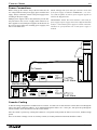
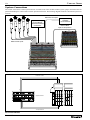
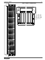
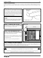
System Connections
The console is the hub of a sound system. Because it controls most of the variables within a system, proper connection and component relationships are vital to assure accurate operation and results. The following diagrams illustrate conventional system connections.
Balanced Line Inputs
Keyboards,
Samplers,
Drum Machines
Input Processing,
via Input Module
Insert Send and Return
Connections
External Mixer
Input via Group Bus In
C ENTURY
Balanced Mic Inputs
10
0
C ENTURY
10
0
10
0
10
0
10
0
10
0
10
0
10
0
10
0
10
0
10
0
10
0
10
0
10
0
5
0
10
0
10
0
10
0
10
0
10
0
10
0
10
0
10
0
0
5
10
0
5
10
10
0
0
5
5
10
0
5
10
0
5
10
10
0
0
5
5
10
10
10
0
0
0
5
5
5
10
10
0
10
0
5
0
5
5
10
10
0
0
5
5
5
5
5
5
5
5
5
5
5
5
5
5
5
5
5
5
5
5
5
5
5
10
10
10
10
10
10
10
10
10
10
10
10
10
10
10
10
10
10
10
10
10
15
15
15
15
15
15
15
15
15
15
15
15
15
15
15
15
15
15
15
15
15
15
15
20
20
20
20
20
20
20
20
20
20
20
20
20
20
20
20
20
20
20
20
20
20
20
30
30
30
30
30
30
30
30
30
30
30
30
30
30
30
30
30
30
30
30
30
30
30
40
40
40
40
40
40
40
40
40
40
40
40
40
40
40
40
40
40
40
40
40
40
40
60
60
60
60
60
60
60
60
60
60
60
60
60
60
60
60
60
60
60
60
60
60
60
10
10
10
10
15
15
15
15
30
40
60
60
BAL
RTN
BAL
RTN
BAL
RTN
BAL
RTN
BAL
RTN
BAL
RTN
BAL
RTN
A
A
A
LEFT
LEFT
L
T
A
P
E
L
S
T
R
I
N
R
P
G
M
R
L
M
N
T
R
O
U
T
R
L
A
L
T
O
U
T
R
To Input Channels
PAGE 10
1
2
4
6
8
Master
Aux Connections
20
30
40
60
LEFT BAL OUT
LEFT
20
30
40
60
INSERT SEND
A
20
30
40
60
RIGHT BAL OUT
LEFT
20
30
40
60
Signal Processors
Out
20
30
40
60
INSERT SEND
EXT
IN
5
10
15
20
30
40
60
MONO BAL OUT
AUX
IN
0
10
15
20
30
40
60
INSERT SEND
EXT
IN
10
10
15
20
30
40
60
EXT TB IN
AUX
IN
5
10
15
20
30
40
60
EXT TB OUT
EXT
IN
0
10
15
20
30
40
60
GRP BAL OUT
AUX
IN
10
10
15
20
30
40
60
INSERT SEND
EXT
IN
5
10
15
20
30
40
60
GRP BAL OUT
AUX
IN
0
10
15
20
30
40
60
INSERT SEND
OUT
M
A
T
R
I
X
10
10
15
20
30
40
60
GRP BAL OUT
OUT
M
A
T
R
I
X
5
10
15
20
30
40
60
INSERT SEND
OUT
M
A
T
R
I
X
0
10
15
20
30
40
60
GRP BAL OUT
OUT
M
A
T
R
I
X
10
10
15
20
30
40
60
INSERT SEND
BUS
IN
5
10
15
20
30
40
60
In
BUS
IN
0
10
15
20
30
40
60
From Aux 1-8 Out
BUS
IN
10
10
15
20
30
40
60
Input Connections
BUS
IN
5
10
15
20
30
40
60
0
5
10
0
10
15
20
30
40
10
5
10
10
10
15
20
10
10
10
15
A
U
X
O
U
T
P
U
T
S
3
5
7
A
U
X
O
U
T
P
U
T
S
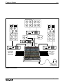
CENTURY SERIES
VX
8001 Professional Power Amplifier
Clip/Limit
Signal
Temp/DC
Active
-6
-10
-6
-10
-3
-15
-3
-15
-1
-30
-80
-1
-30
-80
0dB
Ch A
0dB
Ch B
Local Monitor L
Local Monitor R
7001 Professional Power Amplifier
Clip/Limit
Signal
Temp/DC
Active
-6
-10
-3
-6
-10
-15
-3
-15
-1
-30
-80
0dB
Ch A
-1
-30
-80
0dB
Ch B
Center
Out
From Local
Monitor Out
Left Out
Right Out
8001 Professional Power Amplifier
8001 Professional Power Amplifier
C ENTURY
Clip/Limit
Clip/Limit
Signal
Signal
Temp/DC
Temp/DC
Active
Active
-6
-10
-6
-10
-3
-15
-6
-3
-10
-15
-1
-30
-80
0dB
Ch A
-6
0dB
-80
Ch B
0dB
Ch A
Input Channel
Direct Outs
feed to remote
mixer/recorder
-3
-15
-1
-30
-80
-10
-3
-15
-1
-30
-1
-30
-80
0dB
Ch B
Matrix Outputs
to remote
location, mixer,
or recorder
10
0
5
10
0
5
10
0
5
10
0
5
10
0
5
10
0
5
10
0
5
10
0
5
10
0
5
10
0
5
10
0
5
10
0
5
10
0
5
10
0
5
10
0
5
10
0
5
10
0
5
10
0
5
10
0
5
10
0
5
10
0
5
10
0
5
10
0
5
10
10
10
10
10
10
10
10
10
10
10
10
10
10
10
10
10
10
10
10
10
10
10
15
15
15
15
15
15
15
15
15
15
15
15
15
15
15
15
15
15
15
15
15
15
15
20
20
20
20
20
20
20
20
20
20
20
20
20
20
20
20
20
20
20
20
20
20
20
30
30
30
30
30
30
30
30
30
30
30
30
30
30
30
30
30
30
30
30
30
30
30
40
40
40
40
40
40
40
40
40
40
40
40
40
40
40
40
40
40
40
40
40
40
40
60
60
60
60
60
60
60
60
60
60
60
60
60
60
60
60
60
60
60
60
60
60
60
Headphone Outputs:
1 under armrest,
1 in Master Module
Output Connections
PAGE 11
VX
CENTURY SERIES
2
8
1
4
10
5
7
2
8
1
9
10
0
LINE
4
GAIN
40
30
50
20
70
80
150
40
300
20
5
400
HPF
Ø
7
2
A
U
X
8
1
9
10
0
4 5 6
S
E 3
7
N
8
D 2
S 1
9
10
0
P
4 5 6
U
7
S 3
H
2
8
O 1
9
N
10
0
O
4 5 6
F
7
F 3
2
4
8
HF
7
8
9
10
0
4
20K
5
2
2
4
HM
8
9
10
0
DIR OUT
400
PRE
8K
PAN
Q
4
1K
2
MUTE
100
2K
L
C
R
P
A
N
M
Q
200
LF
4
100
6
L
R
1
2
3
4
5
6
7
8
800
40
PEAK
EQ IN
4
5
3
SOLO
PK
8
1
9
4
5
3
7
2
-6
8
1
10
SIG
9
10
0
4
5
3
6
3
7
2
9
4 5 6
S
E 3
7
N
8
D 2
S 1
9
10
0
P
4 5 6
U
7
S 3
H
2
8
O 1
9
N
10
0
O
4 5 6
F
7
F 3
2
4
5
6
1
8
7
8
15
6
20
A
M
U
T
E
9
4
5
7
6
3
7
2
9
5
G
R
O
U
P
S
D
10
0
4
8
6
3
B
C
8
1
A
D
7
2
8
1
9
0
DIR OUT
5
10
10
0
0
G
R
O
U
P
S
4
5
8
1
V
C
A
3
10
0
1
2
8
1
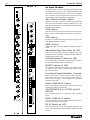
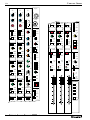
LINE Switch
Switches between the balanced female XLR microphone
Input connector and the balanced Line Input 1/4" TRS connector.
PAD Switch
10
PRE
PAN
Adjusts input gain for proper signal level. Maximum gain is
70 dB.
SAFE
Reduces all low frequency content at a -12dB per octave rate
adjustable from 20 to 400 Hz (-3dB point). Yellow LED illuminates when switch is down.
Polarity Reverse Switch w/LED
Inverts the polarity of both the microphone and line inputs.
The red LED illuminates when switch is down.
INSERT Switch w/LED
Activates the send-return insertion point. The send is always
on. Audio from the return is switched into the channel when
the switch is pressed.
Four-Band Sweep Equalizer Controls
0
2
6
VCA
+8
10
0
PAGE 12
1
7
2
A
U
X
1
6
Applies 48 Volts DC to pins 2 & 3 of the microphone input
XLR jack for microphones requiring phantom power. The
XLR input is balanced and accepts high quality microphones,
DI boxes and line sources.
Adjustable High Pass Filter w/LED
LM
6
48V Phantom Power Switch
GAIN Control
6
6
The input module is the main method by which input signals
are brought into the console. The Vx input module takes the
new features introduced with the GTx console and adds a
more flexible Aux send/assignment Section and extensive
VCA (Voltage Controlled Amplifier) functionality.
Introduces a -15 dB attenuation to the mic input signal, useful
when handling high-level signals.
7
1
1K
8
6
3
PEAK
7
6
3
1
1.5K
6
10
5
2
15
5
9
0
INSERT
4
8
1
3
3
6
3
PAD
2
6
3
+48V
Vx Input Module
9
0
INPUT
There are two knobs for each of the four bands. The inner
knob controls the boost or cut (15 dB); the outer knob controls the center frequency. Center frequencies are indicated
around the outer knob.
PEAK/SHELVE HF Switch
Used for switching the high frequency EQ between the normal shelving setting to a peak setting.
SWITCHABLE Q on HI MID and LO
MID EQ
Q is switchable between .8 (switch up) and 1.8 (switch
down).
30
40
60
PEAK/SHELVE LF Switch
Used for switching the low frequency EQ between the normal shelving setting to a peak setting.
EQ IN Switch w/LED
Inserts the EQ section into the input channel (post insert, pre
fader). An associated green LED illuminates when the switch
is down.
CENTURY SERIES
AUX SENDS 1- 8 Individual Level
Controls
These Push-On/Push Off pots adjust signal level sent to
respective Aux buses. Pushing the switch down turns the send
on or off. An associated two color LED indicates status: OFF
indicates an 'off' state; GREEN indicates the Aux send is on,
and not muted; RED indicates the Aux send is on, but muted.
The signal source for these mixes may be selected (by Aux
bus) to be pre or post fader by the GLOBAL switches located
in the Vx Master section.
Aux 8 DIR OUT Switch w/LED
VX
Fader
100mm linear VCA level control, adjusts the level to all
'POST' fader outputs, ie auxiliaries 1-8 selected post, AFL,
Group assigns 1-8, L, R & Mono output mixes. Local fader
movements combine with movements of any VCA Group
faders the channel is assigned to. The change in audio level is
the sum of the two. If the Group fader is closed no local movements will be heard. If the Group is at -5, local fader settings
will be reduced 5dB. Refer also to Expansion and muting.
VCA Group 1-8 selectors
Removes the Aux 8 signal from the Aux 8 bus, and assigns the
signal to the direct out 1/4" connector on the rear panel, instead
of the normal post fader Dir Out signal.
Assign the channel to the VCA group control buses. Puts the
channel audio level under the (remote) control of the VCA
Group fader along with other channels assigned to the same
group. Independant of the Group Audio Assign section above.
AUX 8 PRE Switch w/LED
VCA LED
Switches the Aux 8 signal source between pre and post-fader.
Indicates VCA gain (i.e., gain of fader stage) via a two-color
LED. Indications are as follows: Green - intensity indicates
gain status (gain of fader stage). Red - indicates maximum
VCA gain has been reached, approximately 15dB. When the
gain LED is red then further requests for increased level, by
moving the channel fader or the VCA Group fader up, will
produce no response.
PAN CONTROL
Positions the channel image between left and right or between
left-center-right; operates with groups when pan switch is
selected. (See L-C-R Switch).
In LCR mode, continuous variation is available between full
level to left only (pan full counter-clockwise position) full
level to right only (pan full clockwise) and center position (full
level to mono/center, no output to left or right).
MUTE Switch w/LED
Turns off the channel audio to outputs. LED on = audio off.
Both pre and post fader audio is muted. When pre-fader sends
should not mute refer to USER OPTIONS. MUTE responds to
the local switch, the Mute Groups, and VCA Group Mute
(internal user option).
Mute Group selectors A-D
Assign input channels to any of the four Scene Mute groups.
Mute response occurs only when the group Master has been
activated.
Mute Groups Safe Switch w/LED
Bypasses the selected Scene Mute assignments. No Scene
Mutes can occur. An associated green LED indicates the channel is in a SAFE (isolated) state.
MONO Bus Assign Switch
Assigns the input signal to the Center / Mono bus. If L-C-R is
selected then PAN adjustment will be effective.
L-C-R Switch
Changes the PAN function from normal L-R to L-C-R operation. The mix to the L,R & Mono buses is adjustable with L-CR PAN. Refer to Special facilities for more information.
PAN Switch / Group Assign
Switches (1-8) w/LED's
Group assign switches route the post-fader signal to the Group
buses. PAN does not adjust these outputs unless the PAN
switch is selected. Then the L & R sides of the control correspond to Odd and Even Group bus numbers.
SOLO Switch w/LED
Operator monitor facility, switches channel audio into the
headphones and Solo Meters. Choice of PFL or AFL is made
in the center master section. AFL is after fader, after Pan pot,
and after mute.
5-Segment LED Array
Dedicated channel level meter connected pre-fader, post EQ
(post fader option, refer to User Options). Top red Peak LED
responds to audio levels pre EQ, post EQ and post-fader.
Normal indication is green on, red flashing only on loud peaks.
PAGE 13
VX
CENTURY SERIES
2
8
1
STEREO
—
10
5
4
7
2
8
1
9
10
0
LINE
5
4
40
GAIN
30
50
20
80
70
150
40
300
400
20
HPF
Ø
7
2
A
U
X
1
1
5
4
7
8
1
5
3
7
8
1
18
9
10
0
5
4
HF
8
7
1
9
10
16
1K5
STEREO
4
600
5
300
LR
BAL
MONO
IMG
WID
8K
LCR
BAL
MID
– O +
8
STR
8
REV
MUTE
16
16
300
500
L
C
R
S
U
M
M
100
6
L
R
1K
40
LF
– O +
8
8
16
16
1
2
3
4
5
6
7
8
EQ IN
4
5
8
PK
9
4
SIG
10
0
5
7
2
PK
8
1
SIG
9
5
10
8
1
V
C
A
9
10
0
S
4 5 6
E 3
7
N
8
D 2
S 1
9
10
0
P
4 5 6
U
7
S 3
H 2
8
1
4
5
0
G
R
O
U
P
S
10
9
4
5
6
6
3
15
7
2
20
8
9
10
0
4
5
7
6
3
7
2
8
1
9
10
0
4
5
8
6
3
8
1
10
STEREO
MONO
30
40
60
G
R
O
U
P
S
SAFE
9
0
M
U
T
E
A
D
7
2
LR
BAL
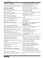
Introduces a -20 dB attenuation to the mic input signal for both
L and R XLR inputs.
L GAIN & R GAIN Controls
Adjustable High Pass Filter w/LED
For both Left and Right inputs, reduces all low frequency content at a -12db per octave rate adjustable from 20 to 400 Hz (3dB point). Yellow LED illuminates when switch is down.
Polarity Reverse Switch w/LED
For L&R channels, inverts the polarity of both the microphone
and line inputs. An internal jumper selects between Left channel only or both Left & Right channels (default). When this
switch is pushed, an associated LED lights.
INSERT Switch w/LED
Activates the insertion point. The send is always on. Audio
from the return is switched into the channel when the switch is
pressed.
The equalization controls in this module act upon both L and R
stereo channels at once. All three EQ bands are set up as sweep
EQ’s: the lower knob controls the boost or cut (16 dB); while
the upper knob controls the center frequency adjusted by the
lower knob. Center frequencies are indicated around the upper
knob.
EQ IN Switch w/LED
5
1
8
10
0
1
PAGE 14
R
7
2
Switches between the balanced XLR Microphone Input connector and the balanced Line Input 1/4" TRS connector for
both L and R channels.
Three-Band Sweep Equalizer Controls
3
6
3
IMG
WID
VCA
10
0
4
L
2
6
3
O
N
O
F
F
SOLO
1
7
1
A
U
X
1
6
3
2
LINE Switch
These concentric controls adjust input gain for proper signal
level for both Left and Right inputs. Maximum gain is 70 dB.
Inner knob is for L GAIN, outer knob is for R GAIN.
8
0
16
8
6
3
2
8
7
6
2
Applies 48 Volts DC to pins 2 & 3 of the both L and R XLR
inputs, for microphones requiring phantom power.
PAD Switch
9
10
0
20K
6
6
3
12
5
9
2
2
– O +
4
10
0
4
1K
48V Phantom Power Switch
9
10
0
O
N
O
F
F
The Vx Stereo Input module is essentially two Vx Input modules packaged to fit into a one-module space. This module is
very useful for accepting remote feeds, effects outputs and
other signals that require stereo handling.
8
S
4 5 6
E 3
7
N
8
D 2
S 1
9
10
0
P
4 5 6
U
7
S 3
H 2
8
INSERT
5
3
6
3
PAD
2
6
3
+48V
Vx Stereo Input Module
9
0
Inserts the EQ section into both L and R input channel signals
at once. An associated green LED illuminates when the switch
is down.
AUX SENDS 1- 8 indiv. level controls
The Aux Individual Level Controls send a summed (L+R) signal to the AUX outputs. These Push-On/Push Off pots adjust
signal level sent to respective Aux buses. Pushing the switch
down turns the send on or off. An associated two color LED
indicates status: OFF indicates an 'off' state; GREEN indicates
the Aux send is on, and not muted; RED indicates the Aux
send is on, but muted. The signal source for these mixes may
be selected (by Aux bus) to be pre or post fader by GLOBAL
switches located in the Vx Master section.
CENTURY SERIES
VX
STEREO Switch w/LED
L&R PEAK & SIG LEDs
Like the AUX 1-6 controls, AUX 7&8 Individual Level
Controls normally send a summed (L+R) signal to the AUX
outputs. When the STEREO switch is depressed, AUX 7 and 8
become a send ‘left’ and ‘right’ send respectively. This can be
used for a stereo effects send.
Input level metering for the L and R channels. The green signal
LEDs turn on at about -30dB and brighten with increasing
level. They show the pre-amp output levels.
WIDTH Control / Balance
Fader
Dual concentric control pair. Outer control sets image width
for the outputs to L, R and Mono. The outputs to Group buses
are not affected by Image Width.
STR = normal stereo
MONO = summed L&R in both channels
REV = mirror image of normal
Inner control 'Balance' adjusts image position, extreme L and
extreme R setting attenuate the opposite sides about 20dB.
When LCR is selected, the Balance control changes function.
Fully clockwise = full level to center, no signal to L&R
Red peak LEDs turn on 3dB before overload and show the levels post-fader, pre-fader and at the preamp output.
100mm VCA fader adjusts the channel stereo audio level.
Controls all outputs of the channel except those Aux output
sections selected pre-fader.
VCA Group 1-8 selectors
Assign the channel VCA to the VCA group control buses. Puts
the channel audio level under the (remote) control of the VCA
Group fader along with other channels assigned to the same
group. Independant of the Group Audio Assign section above.
VCA LED
combines L&R audio into a mono mix for the assigns to group
mixes only.
Indicates VCA gain (i.e., gain of fader stage) via a two-color
LED. Indications are as follows: Green - intensity indicates
gain status (gain of fader stage). Red - indicates maximum
VCA gain has been reached, approximately 15dB. When the
gain LED is red then further requests for increased level, by
moving the channel fader or the VCA Group fader up, will
produce no response.
MUTE Switch w/LED
Mute Group selectors A-D
Mutes the channel and all send functions. Mute also responds
to the Mute Group system and to the VCA Group Mute if
selected (refer to User Options). The LED illuminates when
the channel is muted.
Assign input channels to any of the four Scene Mute groups.
Mute response occurs only when the group Master has been
activated.
MONO Bus Assign Switch w/LED
Bypasses the selected Scene Mute assignments. No Scene
Mutes can occur. An associated green LED indicates the channel is in a SAFE (isolated) state.
Fully counter-clockwise = full level to L&R, none to center
50% rotation = equal levels to L, R & Center outputs.
SUM
Assigns audio to the Mono bus.
LCR Switch with Indicator
Mute Groups Safe Switch w/LED
Controls the function of the L-R and M assign switches in
combination with the Balance control. When LCR is selected,
the Balance control provides continuous variation of outputs to
the L, R & Mono mixes.
Full clockwise = full level to mono, none to L-R.
Full counter-clockwise = full level to stereo, none to mono.
Refer also to Special facilities.
Bus Assign Switches,L-R & Mono
w/LEDs
Connect the post fader stereo audio to the output buses. These
outputs are always affected by the Width and Balance controls.
Balance provides L-C-R panning function to the three output
buses when the LCR switch is selected.
SOLO Switch w/LED
Operator monitor facility, switches channel audio into the
headphones and SOLO meters in stereo. Choice of PFL or
AFL. Unaffected by mutes.
PAGE 15
VX
CENTURY SERIES
2
8
1
MULTI-INPUT
9
0
10
4
5 6
3
MIC
2
+48V
8
1
MIC
+48V
C
PAD
A
PAD
GAIN
40
MIX
TRIM
0
30
50
L
R 20
GAIN
40
30
50
L
R 20
-15
70
70
+6
80
ON
150
ON
40
300
L•ONLY•R
MONO
HPF
MONO
SIG
Ø
SIG
5
S
4
E 3
N
D 2
S
1
0
P
4
U
S 3
H 2
L PFL R
9
10
7
8
9
10
7
8
9
10
7
8
9
0
10
4
5 6
+48V
16
16
1K5
4
7
8
9
0
10
4
5 6
7
8
+48V
1
9
10
5
B
PAD
300
GAIN
40
30
MID
8
R 20
R 20
STR
REV
500
6
LF
– O +
8
SIG
8
16
L
C
R
L
R
S
U
M
1
2
3
4
5
6
7
8
MONO
1K
40
M
L•ONLY•R
100
L•ONLY•R
MUTE
16
300
MONO
LCR
BAL
70
ON
70
LR
BAL
8
16
ON
MONO
50
L
8K
– O +
IMG
WID
30
50
L
STEREO
GAIN
40
8
3
2
D
PAD
600
7
3
0
MIC
6
5 6
2
20K
MIC
5
5 6
1
HF
4
5 6
1
8
3
8
18
8
5 6
7
2
– O +
4
2
A
U 1
X
0
12
1K
10
3
INSERT
L PFL R
9
0
O 1
N
0
O
4
F 3
F
2
400
20
L•ONLY•R
2
7
SIG
L PFL R
16
L PFL R
EQ IN
4
7
2
10
4
5 6
3
MIC
+48V
GAIN
40
50
L
R 20
7
8
1
9
0
10
4
5 6
3
30
70
ON
L•ONLY•R
SIG
2
A
U 1
X
0
S
4
E 3
N
D 2
S
1
0
P
4
U
S 3
H 2
L PFL R
30
PAGE 16
GAIN
4
5 6
7
8
9
10
5
5 6
10
BAL INPUT
0
G
R
O
U
P
S
L
INSRT RTN
RIGHT
C
R
5
1
8
7
8
10
9
10
20
7
8
9
10
4
5 6
7
7
8
1
9
0
10
4
5 6
8
3
7
2
8
1
BAL INPUT
15
6
5 6
2
M
U
T
E
L
30
40
BAL INPUT
A
60
G
R
O
U
P
S
R
IMG
WID
A
D
SAFE
9
10
MONO
LR
BAL
L
D
R
STEREO
D
40
R
INSRT SND
RIGHT
V
C
A
8
0
0
PAD
R
3
9
1
+48V
INSRT RTN
LEFT
VCA
PK
SIG
10
3
MIC
L
7
O 1
N
0
O
4
F 3
F
2
MONO
2
2
C
PAD
SIG
9
0
L
B
PK
8
1
BAL INPUT
SOLO
1
5 6
3
INSRT SND
LEFT
VX MULT INPUT
CENTURY SERIES
VX
Optional Multi-Input Module
The left side of this double-module provides four stereo inputs
which are summed together creating a stereo sub-mix. The
right side takes that mix and processes it as a stereo source into
the Vx. The right side (called Multi Master) is similar to a regular Vx Stereo Input module, except that the Input Gain pot
and switches are replaced by a mix trim stereo level control.
Panel controls (each of four identical inputs)
MIC input selector
for the L & R Input XLRs. The default (with the switch
released) is Line Input sensitivity and gain.
+48V phantom power ON-OFF switch
for the input XLRs. Active only when MIC source selected.
PAD switch
for introducing 15dB attenuation between the XLRs and the
preamp.
GAIN dual- concentric control pair
for the stereo preamp.
ON-OFF switch with indicator
for the preamp output to the stereo sub-mix.
L & R assign switches
for the preamp output to the stereo sub-mix.
For normal Stereo output release both switches. Use either L or
R alone to send one side of the input to both sides of the mix.
Select both switches for a mono mix of both inputs to the
stereo mix.
SIGNAL indicators
for L & R audio, bi-color indication: normal level = green;
overload = red.
PFL switches with indicators
for the L & R inputs.
Rear panel connections
Insrt Snd (Left/Right)
This balanced 1/4" TRS jack allows for the Left and Right
multiple input module output signals to be sent to effects or
signal processors.
Insrt Rtrn (Left/Right)
This balanced 1/4" TRS jack allows for the return of the effected and/or processed signal back into the multiple input module.
Bal Input (L/R) A, B, C, D
These balanced XLR connectors accept input signals for the A,
B, C, and D stereo inputs of the multiple input module.
PAGE 17
VX
CENTURY SERIES
SOLO
GROUP
—
MATRIX
STR
PGM
5
4
MUTE
L
R
6
3
MATRIX OUT
7
1
0
4
4
3
7
9
8
9
7
2
10
0
MONO
6 EXT
LCR
8
9
1
0
PAN
10
5 6
4
LEV
6
3
2
1
10
5
5
8
2
G1
3
7
2
8
1
9
MUTE
10
0
5 6
4
G2
3
7
2
8
1
9
10
0
5 6
4
G3
3
7
2
8
1
FADER
REV
9
10
0
5 6
4
G4
3
7
2
MATRIX
METER
8
1
9
10
0
G5
5 6
4
3
7
2
8
1
9
10
0
5 6
4
LCR
G6
3
7
2
8
1
M
9
10
0
5 6
4
G7
3
7
2
L
R
8
1
9
0
10
4
5 6
G8
3
7
2
MATRIX
POST
8
1
9
PEAK
10
0
SIG
TB
1
SIG/PEAK
SOLO
AUDIO GROUP
VCA
GROUP
10
MUTE
MUTE
5
MATRIX OUT
4
5
LEV
6
3
7
2
1
8
9
0
0
UNITY
10
5
LCR
PAN
10
15
MUTE
20
30
FADER
REV
MATRIX
METER
PAGE 18
CENTURY SERIES
VX
Vx Group Modules
FADER REV w/LED
Each Vx Group module has three sections: Matrix, Audio
Group, and VCA Group. Fully loaded Vx consoles have eight
group modules. Group number is indicated on Solo switch.
Swaps functions between the Matrix level control and the
group fader; one becomes the other.
Group Meter
Assigns the associated Group signal to the Mono bus.
Located on the meter bridge, it indicates the post-fader output
level of the group.
Group L-R Assign
MATRIX Section
Matrix Pre/Post w/LED
STR PGM Switch w/LED
Switches the Matrix send between pre and post-fader settings.
Normally, the signal sent to the Matrix by the L/R LEVEL TO
MATRIX fader is the Left/Right bus signal. This button
switches the signal source to the Stereo Program In signal.
Green LED indicates selection.
Group Peak & Signal LED’s
L/R Level to Matrix
Audio Group Solo w/LED
Dual control pair. Controls Left & Right level into the Matrix.
Mono/Ext Level to Matrix
Dual control pair. Controls Mono output level and the External
Input level added to the Matrix.
Group Mono Assign
Assigns the Group signal to the Left and Right buses.
The red LED indicates that the group signal is within 3dB of
the clipping point. The green LED constantly displays the level
of group signal activity by varying in intensity.
Allows for monitoring of the Group signal on meter and headphones. Choice of PFL or AFL is made in the Master section.
AFL is after the Group fader and mute.
VCA GROUP Section
Group to Matrix Levels (G1-G8)
VCA Group Fader
Adjusts the level of group signal added to the Matrix.
100mm VCA control fader. Sends a control voltage to any
inputs assigned to that VCA group.
TB to Matrix w/LED
Enables the Talkback path into the Matrix.mix. Talkback will
be heard when it is turned on at the Master ON switch.
PEAK/SIG LED
Indicates signal level of the Matrix.
Green=Signal Present; Red=Peaking Signal
SOLO Switch w/LED
This switch sends the associated Matrix signal to Solo.
MATRIX OUT Level w/LED
This rotary fader controls the master level of the associated
Matrix to the rear XLR connector.
VCA Group Mute w/LED
Attenuates any inputs assigned to that VCA. VCA group mute
is a fader position change; this is different to input mute. (Can
be changed to function as an input mute via an internal
jumper.)
UNITY LED
Indicates when VCA control fader is at “Unity Gain”, a position where any inputs subsequently assigned to that VCA will
not receive any gain change upon assignment. This permits
assignment of inputs to VCA's ‘on the fly’, without affecting
the mix at the fader stage.
GROUP Section
PAN CONTROL
Positions the Group image between left and right or between
left-center-right.
L-C-R Switch
Changes the PAN function from normal L-R to L-C-R operation. The mix to the L, R & Mono buses is adjustable with LC-R PAN. Refer to Special facilities for more information.
MUTE Switch w/LED
Turns off the Group audio to outputs. LED on = audio off.
MONO Bus Assign Switch
Assigns the input signal to the Center / Mono bus. If L-C-R is
selected then PAN adjustment will be effective.
Group Fader
100mm linear audio fader. Controls all group signal outputs to
the mix and output XLR
MATRIX METER Switch w/LED
Displays Matrix signal on associated Group meter.
PAGE 19
VX
CENTURY SERIES
3
1
RIGHT
—
AUX
LEFT
—
AUX
MONO
—
ALT
9
0
SOLO
SOLO
MASTER
—
10
EXT TB
IN
MONO
L-R
-0+
-0+
HF
8
8
8
EXT TB
OUT
TB
MIC
HF
8
4
16
16
16
-0+
8
4
16
16
5
2
8
1
9
DC
POWER
IN
+48
5
6
7
2
8
1
MUTE
MONO
L•R
L•R
4
5 6 GAIN
7
2
SOLO
SOLO
GLOBAL
PRE
STEREO
PROGRAM IN
AUX OUT 5
AUX OUT 6
SIG/PEAK
SOLO
SOLO
-0+
4
5
LEV
6
8
÷5
16
2
8
1
4
9
16
GLOBAL
PRE
AUX OUT 1
AUX OUT 2
SOLO
SOLO
0
4
10
5
4
5 6
7
LEV
1
LEV
7
0
10
4
5 6
0
10
4
10
AUX OUT 4
SOLO
L-R
+
CENTER
AUXES
5 6
4
5
6
PEAK
PEAK
PEAK
8
SIG
SIG
SIG
7
BAL
4
5
3
6 LEV
7
2
RIGHT
LEFT
SOLO
SOLO
2
8
1
4
LEV
6
2
4
8
SOLO
8
AFL
9
PFL
EXT TB
IN
0
0
0
SOLO
TYPE
SOLO CONTROL
MUTE GROUP
MASTERS
LEV
6
7
2
8
1
9
A
9
10
0
10
0
5
3
7
1
9
10
0
5
3
7
8
9
10
MUTE
MUTE
LEV
6
7
HEADPHONES
SOLO
EXT TB
OUT
5
LEV
SOLO
DEFEAT
L-R
4
6
2
0
10
0
MONO
3
5
1
MONO
CENTER
9
10
MATRIX
POST
3
7
8
MATRIX
POST
MATRIX
POST
2
1
MUTE
TAPE
3
1
AUX
7• 8
3
0
SOLO
MONO
MUTE
4
GLOBAL
PRE
AUX OUT 3
MONO
MONITOR OUT
GROUPS
8
0
10
GLOBAL
PRE
MUTE
L-R
9
1
9
MUTE
ALT L/R OUT
MONO
AUX
5• 6
1
SUM
MONO
SUM
MONO
7
2
8
1
9
0
5 6
4
3
2
8
AUX MUTE
ACTIVE
TB/OSC ASSIGN
9
2
MUTE
AUX MUTE
ACTIVE
8
1
3
MUTE
ON
7
2
DIM
+ CENTER
OSCILLATOR
AUX
3• 4
6
SOLO
10
MUTE
9
3
SOLO
0
PRE
PINK
NOISE
8
1
AUX OUT 8
8
9
1
10
GLOBAL
PRE
6 LEV
7
9
7
2
10
5
2
8
9
0
4
3
7
10
AUX
1• 2
5 6
3
10
GLOBAL
PRE
3
+
LEV
6
1
AUX OUT 7
8
5
2
8
9
0
4
3
7
GLOBAL
PRE
6 LEV
7
2
0
7
0
2
3
8
16
10
X2
5
1
LEV
5 6
4
3
9
4
LF
8
10
L-R
MUTE
LEV
6
1
9
0
8
5
2
8
1
4
3
7
2
FREQ
HF
MUTE
MUTE
0
TAPE
SOLO
MUTE
MUTE
100HZ
- 0+
1
TALKBACK
SOLO
DEFEAT
1KHZ
10
16
8
9
10
0
9
0
STEREO
AUX IN B
STEREO
AUX IN A
2
8
1
GLOBAL
PRE
3
LEV
2
8
9
10
10KHZ
8
1
7
7
CENTER
MONO
5 6
LEV
6
HEADPHONES
3
4
5
10
MUTE
3
4
3
7
0
+24
9
0
10
LEV
6
1
9
10
0
5
2
8
1
4
3
7
-20
LEV
3
7
ADDITIONAL JACKS
LOCATED BELOW
ARMREST
+20
16
4
6
3
0
8
LEV
6
2
LF
8
5
3
LAMP DIM
-0+
LF
8
16
16
MUTE
MUTE
MUTE
GLOBAL
PRE
GLOBAL
PRE
STEREO
PROGRAM IN
AUX OUT 5
AUX OUT 6
SIG/PEAK
SOLO
SOLO
TALKBACK
15
15
15
20
20
20
25
25
25
30
30
40
40
TAPE
SOLO
B
C
L-R
+
D
CENTER
SOLO
DEFEAT
4
5
LEV
6
3
7
2
8
1
9
10
0
GLOBAL
PRE
4
5
LEV
6
3
7
2
8
1
9
0
10
GLOBAL
PRE
AUX OUT 7
AUX OUT 8
SOLO
SOLO
4
5
LEV
6
3
7
2
8
1
9
0
10
4
3
5
6 LEV
7
2
8
9
1
0
10
PRE
DIM
+ CENTER
SUM
MONO
SUM
MONO
MUTE
PAGE 20
AUX
MUTE
MUTE
MUTE
30
40
CENTURY SERIES
VX
Vx Master Section
L/R/MONO MUTE Switch w/LED
Comprises four modules and is the control center for the Vx
console. Stereo Aux In, Monitoring, Solo, Talkback, Stereo
Program In, Master Aux & Matrix, internal oscillator & Scene
Muting functions are controlled here.
Mute outputs of Left, Right & Mono signals respectively.
LEFT/RIGHT Modules
Stereo Aux In HF Level
Switches the source of Left, Right and Mono matrix feed signals between pre and post-fader.
Upper-band fixed frequency (10kHz) EQ that affects the associated Stereo Aux in channel.
L/R PEAK/SIG LED's
Stereo Aux In LF Level
Lower-band fixed frequency (80Hz) EQ that affects the associated Stereo Aux in channel.
Stereo Aux In LEV Control
MONO Switch w/LED
Assign the Left and Right signals to the Mono output.
MATRIX POST Switch w/LED
The red LED lights 3dB before clipping point and responds to
pre and post fader levels. The varying intensity of the green
LED displays the level of the mix bus audio.
SOLO Switch w/LED
Controls the level of the Stereo Aux In audio.
Solo monitoring of the L, R or Mono Output. Choice of PFL or
AFL source.
Stereo Aux In MUTE Switch w/LED
Fader
Turns off the audio assigns to the main mixes
Stereo Aux In MONO Switch
100mm linear analog fader for control of the output level to
XLR, matrix and Solo AFL.
Assigns the audio to the Mono bus.
Not Shown:
Stereo Aux In L+R Switch
Left, Right & Mono Insertion points.
Left, Right & Mono Meters.
Assigns the stereo audio to the main L+R mixes, L to L, R to
R.
MONO Module
Stereo Aux In SIGNAL LEDs
Lamp Dim Control
Bi-color LED lights green at normal output levels, red indicates an overload condition. Responds to audio in both L&R
channels, and pre and post level control.
Controls the intensity of the lighting devices plugged into the
XLR sockets on the back of the meter bridge.
Stereo Aux In SOLO Switch w/LED
These four LED’s indicate the status of the incoming DC.
Allows SOLO monitoring of the associated Stereo Aux In signal. Choice of PFL or AFL.
Auxiliary Output MUTE w/LED
Mutes the respective auxiliary XLR output. In addition the
Aux Scene Mute Master facility allows a number of auxes to
be muted at the same time. The mute LED indicates the audio
status and responds to both controls. Refer to the Special
Facilities section for more about Aux Scene Mute.
Aux Master LEV Control
Controls final output signal level of the auxiliary output.
Aux Master GLOBAL PRE Switch
w/LED
This switch changes all Aux sends on input modules for the
associated Aux bus to be Pre-Fader or Post-Fader. Up=Pre,
Down=Post. The associated LED is green in color.
Power Indicators
Stereo Program In Gain
Adjusts the gain of the Stereo Program In signal.
Stereo Program In EQ
Two-band fixed frequency (10kHz and 80Hz) EQ that affects
the Stereo Program
AUX 1&2, 3&4, 5&6, 7&8 Levels
These rotary faders controls the amount of Stereo Program signal sent the respective Aux buses. Normally Left signal is sent
to the odd Aux buses, while Right signal is sent to the even
Aux buses. Refer to Special facilities for more information.
Stereo Program Balance
Provides adjustment of the image position.
Stereo Program Assignments
Assigns the Stereo Program to the Mono and Left/Right buses.
AUX OUT LED
Stereo Program Mute w/LED
Bi-color LED lights green at normal output levels, red indicates an overload condition.
Mutes the output of the Stereo Program.
Aux SOLO Switch w/LED (green)
Controls final output signal level of the Stereo Program.
Solo monitoring facility for the AUX mix. Choice of PFL or
AFL.
Stereo Program SIG/PEAK LED
AUX MUTE ACTIVE LED
Indicator for the Aux Scene Mute facility. Illuminates when
the Aux Scene Mute Master switch has been selected.
Stereo Program Level
The red LED lights 3dB before clipping point and responds to
pre-fader levels. The varying intensity of the green LED displays the level of the audio. Both LEDs respond to the sum of
L&R audio.
PAGE 21
VX
Stereo
w/LED
CENTURY SERIES
Program
SOLO
Switch
Talkback On/Off Switch
Solo monitoring facility for the Stereo Program signal. Choice
of PFL or AFL in stereo.
Turns the talkback/osc output on and off. Press+hold for short
message; press+release to lock on, press+release again to lock
off. Controls all routes including TB to Matrix.
Alt L/R Output facility
Monitor Output system
Stereo output with level control and mute. The source is the
main L&R output, either pre or post output faders. The Mono
mix may be added, it is automatically sourced pre or post fader
in response to the L&R Pre-Post selection. The ALT output
may be operated in Mono when required using the SUM
MONO switch.
Stereo monitoring system with main Level control, Mute
switch and outputs on balanced XLRs. The audio sources are
L+R mix or Stereo Tape Input. The Center/Mono mix may be
added. Normally SOLO interupts the source. The SUM
MONO switch combines the L&R monitor audio into a mono
output.
MASTER Module
Stereo Tape Input
TB MIC Input
Allows for a microphone to be plugged in for use with the talkback system. Accepts balanced low impedance mics. +48V
phantom power is provided. Refer also to User Options.
The stereo audio from the rear panel jacks connects to the
source select switch. If nothing is plugged into these sockets
then STEREO PROGRAM INPUT audio is normallised
through the switch contacts and reaches the source selector.
Headphone Jack
Solo Defeat switch
Stereo 1/4" TRS socket for all types of headphones. A second
HP socket and TB socket are located beneath the front hand
rest.
Prevents SOLO interupting the normal monitor audio. Allows
the monitor output to be used as an additional dedicated output
circuit when necessary. Included with main and headphone
sections.
10kHz/1kHz/100Hz switches
These push buttons select the sine wave frequency generated
by the internal Oscillator. Lowest selected frequency takes priority.
Oscillator FREQ Control
Dim Switch
This switch introduces a -12 dB attenuation into the local monitor outputs. It is disabled when SOLO defeat is depressed,
auto-active when TB is on.
This rotary pot adjusts the selected frequency by a minimum
factor of 0.2 or maximum factor of 2.0. Used in conjunction
with the frequency buttons, tones from 20Hz to 20kHz can be
generated.
Headphone Monitor system
Oscillator LEV Control
Solo Active LED
This rotary fader adjusts the Oscillator level between off and
+4dB.
This LED indicates that SOLO is active.
PINK NOISE Switch w/LED
This switches the generator to pink noise replacing tone.
These LED's indicate which type of SOLOing has been selected.
Oscillator ON Switch w/LED
SOLO type Switch
Turns on the internal oscillator / pink noise generator.
Assigns the TB/Osc audio to the summing buses for Mono,
L,R, Aux 1-8 and Groups 1-8. TB to Matrix is enabled locally
at each Matrix section.
This switch changes solo type from PFL (Pre-Fader Listen) to
AFL (After-Fader-Listen). Both are available from the majority of sections in the console. Both are stereo capable. This
switch choses one or the other. AFL is after fader, pan and
mute.
Talkback Level Control
Mute Group Master Switches+LEDs
Talkback Assignment Switches
Controls the level of the TB/Osc audio.
External Talkback Input Switch
w/LED
Selects the External Talkback Input XLR and adds it to the
local mic or tone signal. The XLR is balanced and accepts high
level audio.
External Talkback Output Switch
w/LED
Turns on the external talkback XLR. The output is local mic or
tone but not Ext mic.
PAGE 22
Stereo output, with two sockets in parallel, and level control.
The sources are the same as for the main monitor circuit and
may be selected independantly.
AFL/PFL LED's
All Input channels, including Stereo Inputs are connected with
the Mute Group system. Four switches on each channel may be
used in any combination to select the channel onto the Mute
buses. LEDs on the channels show the selection.
When the Master switch is selected the LED lights and the bus
becomes active. All channels on the bus mute.
At any time a channel may be deselected from the bus. If the
bus was active it will un-mute immediately. If the bus was
inactive the channel mute will not change. When a channel is
already locally muted then the mute group confirms the mute.
When the local mute is released then the channel remains
muted by the mute bus.
CENTURY SERIES
VX
The SAFE facility allows a channel to be isolated temporarily
from the Mute Groups without disturbing the selection.
Mute Groups are part of the Vx Expansion system. Refer to the
Special Facilities section.
Aux Mute Group Switch w/LED
The eight Aux Master Output Mutes are connected to the Aux
Group Mute system. Individual Aux Output Mutes may be preselected using the local switch next to the Level control. The
mute and indicator do not respond directly.
Operation of the Aux Master Mute will mute all Aux Mutes
that have been pre-selected, the LEDs turn on, the Aux Mute
Active LED turns on and the indicator next to the Aux Master
switch turns on.
An individual Aux may be deselected from the Mute Group at
any time using the local mute switch again.
Use this system to control sets of Aux outputs at the same
time, for example to mute FX sends on the last beat of a song
so that reverb tails are heard.
In situations where direct access to Aux mutes is wanted the
system may be adapted, refer to User Options.
Vx Meter Bridge - 52 & 64 Frame Models
-20
-5 -3
-10 -7
-1 0
+1
+2
+3
-20
-5 -3
-10 -7
-1 0
+1
+2
+3
-20
-5 -3
-10 -7
-1 0
+1
+2
+3
-20
-5 -3
-10 -7
-1 0
+1
+2
+3
-20
-5 -3
-10 -7
-1 0
+1
+2
+3
-20
-5 -3
-10 -7
-1 0
+1
+2
+3
-20
-5 -3
-10 -7
-1 0
+1
+2
+3
-20
-5 -3
-10 -7
-1 0
+1
+2
+3
-20
Level
1
Level
2
Level
3
Level
Level
Level
Level
-5 -3
-10 -7
-1 0
+1 +2
+3
-20
-5 -3
-10 -7
-1 0
+1 +2
+3
-20
-5 -3
-10 -7
-1 0
+1 +2
+3
-20
-5 -3
-10 -7
-1 0
+1 +2
+3
-20
-5 -3
-10 -7
-1 0
+1 +2
+3
-20
-5 -3
-10 -7
-1 0
+1
8
Level
Groups
Level
Level
-20
-5 -3
-10 -7
-1 0
+1
+2
+3
-20
-5 -3
-10 -7
-1 0
+1
Level
+2
+3
-20
-5 -3
-10 -7
Level
2
1
Level
Level
Center
Mono
Right
Left
+2
+3
Level
Level
7
6
5
4
-1 0
+1
+2
+3
-20
-5 -3
-10 -7
-1 0
+1
Level
3
Auxes
GROUP Meters
SOLO L & SOLO R Meters
Indicate the post-fader output of Group buses.
Indicate level of any signal selected for PFL.
+2
+3
-20
-5 -3
-10 -7
Level
5
4
Solo R
Solo L
-1 0
+1
+2
+3
-20
-5 -3
-10 -7
-1 0
+1
Level
+2
+3
-20
-5 -3
-10 -7
Level
7
6
-1 0
+1
+2
+3
Level
8
CENTURY
LEFT, RIGHT & CENTER/MONO Meters
AUX Meters
Indicate the post-fader output of the Left, Right, Center/Mono channels.
Indicate the 8 Aux output levels.
Vx Meter Bridge - 44 Frame Model
-20
-5 -3
-10 -7
-1 0
+1
+2
+3
-20
-5 -3
-10 -7
-1 0
+1
+2
+3
-20
-5 -3
-10 -7
-1 0
+1
+2
+3
-20
-5 -3
-10 -7
-1 0
+1
+2
+3
-20
-5 -3
-10 -7
-1 0
+1
+2
+3
-20
-5 -3
-10 -7
-1 0
+1
+2
+3
-20
-5 -3
-10 -7
-1 0
+1
+2
+3
-20
-5 -3
-10 -7
-1 0
+1
+2
+3
-20
Level
1
Level
2
Level
3
Level
Level
5
4
Level
6
Level
7
-5 -3
-10 -7
-1 0
+1
+2
+3
-20
-5 -3
-10 -7
-1 0
+1
+2
+3
-20
-5 -3
-10 -7
-1 0
+1
+2
+3
-20
-5 -3
-10 -7
-1 0
+1
+2
+3
-20
-5 -3
-10 -7
-1 0
+1
+2
+3
Level
8
Groups
Level
Left
Level
Level
Right
Center
Mono
Level
Level
Solo L
Solo R
CENTURY
GROUP Meters
SOLO L & SOLO R Meters
Indicate the post-fader output of Group buses.
Indicate level of any signal selected for.
LEFT, RIGHT & CENTER/MONO Meters
Indicate the post-fader output of the Left, Right, Center/Mono channels.
PAGE 23
VX
CENTURY SERIES
Special Facilities
Century Vx Console Expansion
The Expansion option is available for all Vx models. Two Vx
consoles may be linked in a Master-Slave arrangement.
Alternatively, a Vx may be linked to a Yamaha PM series
model, or other console.
Included Facilities
The facilities included are:
- links for control of VCA Groups 1-8
- links for Left, Right and Mono audio mixes
- links for Scene Mute groups
- links for Solo PFL and AFL audio mixes
and Solo control
- mode selection: Master-Off-Slave for all functions
A further option is available with the standard Vx Expansion
system. This provides direct access to the Left, Right, Mono
and Aux 1-8 audio buses.
Hardware
Active electronics for the Expansion system are located inside
the console chassis. The 56-way EDAC Expansion connector
is located in the upper chassis cut-out behind Input 1. The
Mode switch is located immediately below the Expansion connector. A link cable is required, and is available in two versions, Vx-to-Vx, and Vx-to-PM. Cable length permits consoles
to sit side by side or in an “L” arrangement.
When fitted, the 56-way Bus expansion option occupies the
second chassis cut-out position.
All audio interfacing is buffered at line level. There are no
chassis connections in the link cable.
The audio group mixes of the two consoles remain independent.
(hardware set reference: Vx Expansion 76D2943-00 +
76D2977-00 July 96)
Linked Console Operation
Set up the two consoles as normal. Provide each console with
its own power supply and back-ups, then connect the link
cable. The Vx-to-Vx cable may be fitted either way around,
internal connections cross over inputs to outputs. The Vx-PM
cable has different connectors at each end.
Modes
The mode switch may be set with power on or off; the system
responds immediately.
Assign the Master console with the Mode switch on the Master
console set to MASTER. Assign the slave console with the
mode switch on the slave console set to SLAVE. (Note that if
both consoles are set to Master then the system rejects both
settings, both consoles respond as slaves until one is set to
Master mode.)
When independent operation of the Slave console is required ,
select the “OFF” mode.
PAGE 24
VCA Operation - Groups
The Master console VCA group faders affect the levels of any
channels assigned to a VCA group on both consoles. VCA
group faders on the Slave console are inactive, while the VCA
unity gain indicators remain functional.
VCA Operation - Group Mutes
Between Vx consoles, the VCA Group Mute function of the
Master console controls all channels assigned to that VCA
Group. VCA Group Mutes on the Slave console are inactive.
Between a Vx and a PM console, there is no transfer VCA
Group Mute function.
Scene Mute Operation
The Master console Scene Mute Master ON-OFF switches (Vx
A-D, PM 1-4) are active for all channels assigned on both consoles. Master switches on the Slave console are inactive. In
response to a master mute, the indicator next to the appropriate
master mute on the slave console lights.
Between Vx and PM consoles, Scene Mutes 5 thru 8 are not
transferred. Some PM models allow independent Master-Slave
selection of Scene Mutes 1-4 and 5-8.
Solo Operation
The Solo meters and headphones of the Master console
respond to a Solo selection on either console. Solo meters and
headphones of the Slave console respond to a Solo selection on
the Slave console only.
Audio Linking
The Left Right and Mono audio circuits between consoles are
high level ground-free connections. The audio paths connect
onto the appropriate summing bus in the Master console and
are controlled by the Mode switch.
Outputs
The console expansion link connection includes the Left, Right
and Mono outputs. These are derived after the Matrix send
Pre/Post switches on the Output sections. The audio outputs
are not affected by the Mode switch.
Inputs
The console expansion link input paths to the Left, Right and
Mono summing buses are active ONLY when the console is in
MASTER mode. In Slave and Off modes the audio circuits are
gated off.
CENTURY SERIES
VX
Special Facilities (cont'd)
LCR PANNING
Operation of center-cluster sound systems requires panning
channels between the Left and Right sides of the main stereo
PA and between the stereo PA and the center system.
Conventional panning systems allow for L-R panning but the
center feed is either all on, full center, or all off, no center. In
practice it is necessary to balance the different sound groups
between center and sides. This requires LCR panning. Active
circuits are combined with a special multi-section pot in the
Input, Stereo Input and Group-to-mix pan sections of Vx consoles.
STEREO PROGRAM INPUT
(located above the MONO Master)
Connections are provided on the rear panel for stereo input to
the Mixes, Auxiliaries and Matrix outputs. Use this section for
music playback or special return input. Access to the Matrix
outputs is direct, bypassing the groups. On each Matrix that
requires Stereo input select the switch next to the level control
pot 'L-R / STR PGM'.
Stereo Program audio from the rear XLR connectors also passes to switching contacts on the TAPE INPUT 1/4 inch sockets.
When nothing is plugged into the TAPE sockets Stereo
Program audio passes to the TAPE monitor source switch.
INPUTS and GROUPS
VCA GROUP MUTES
LCR pan sections include an LCR enable selector. When in
LCR mode, three outputs (Left, Right and Center) are derived
from a single input.
Normally the operation of the VCA Group Mute commands all
the channel VCAs in the group to close. The effect is that all
output assignments are faded out, also the post-fader effects
sends are faded. However pre-fader sends are un-affected. This
may be satisfactory, it depends on the effects and monitor mix
set-up at the time.
Pan central
100% output to Center only
Pan hard left
100% output to Left only
Pan hard Right
100% output to Right only
Between hard left and center
progressively less left and
more center output, no right
output.
In a situation where a pre-fader send had to be muted with the
channel then two possible options are available.
Use the local channel Mute switch to cut the pre-fader send,
either individually or as part of a Mute Group.
Between hard right and center progressively less right and
more center output, no left
output.
Alternatively the console can be set so that VCA Group Mute
sends a Mute command to the channel audio switch in addition
to a fade command to the channel VCA.
Operation of LCR panning requires the L-R and M (mono or
center) assign switches to be selected and the LCR switch
selected.
This choice is called VCA Group Channel Mute option. It may
be set up individually for each VCA Group by selection of an
internal jumper link in the Group Output module.
The monitoring section of the console allows the center mix to
be added to the stereo mix in headphones for checking purposes.
When this is set up, then operation of a VCA Group Mute
switch sends Mute commands to the channel mutes of all channels in the VCA group. The result is to turn off the post-fader
audio outputs to buses, effects etc, AND to mute the pre-fader
sends.
STEREO CHANNELS
LCR panning is provided by the Balance section of the
Width/Balance control.
Select the LCR switch and the L-R and Mono audio assign
switches. Now the inner control 'Balance' operates as an LCR
panpot:
Fully counter-clockwise = full level to L&R, none to center,
50% rotation = equal levels to L, R & Center outputs,
Fully clockwise = full level to center, no signal to L&R
This would be desireable if some of the pre-fader sends were
being used for foldback or effects for example.
PAGE 25
Appendix A
Technical Information
VX
CENTURY SERIES
General Specifications Vx Console
Architect’s & Engineer‘s
Specifications - Vx Console
Technical specifications for the Century Vx console.
The following text should be used when specifying a Century
Vx in a bid or proposal.
Available (Eight Bus) Configurations
20 inputs (32 Frame)
32 inputs (44 Frame)
40 inputs (52 Frame)
52 inputs (64 Frame)
All Century Vx consoles are available with stereo input modules.
Frequency Response
+0.0, -0.5dB, 20Hz to 20 kHz (referenced to 1kHz)
Total Harmonic Distortion
Mic input to Group output
20Hz to 20 kHz at +15dBu
<0.02%
Phase Response
20Hz to 20 kHz
+30°, -20°
Noise (22Hz to 22kHz)
Mic EIN
Mix bus Output Noise (20 ch routed)
Aux bus Output Noise (20 ch routed)
-129 dBu
- 80 dBu
- 80 dBu
Crosstalk (Measured at 1kHz)
Channel Mute
Channel Fader Attenuation
Channel Routing
Channel Aux Send Attenuation
>102 dB
> 96 dB
> 85 dB
> 93 dB
Input/Output Impedances
Mic Input
Line Input
Outputs
4kΩ balanced
>10kΩ balanced
140Ω balanced
Input/Output Levels (0VU = +4 dBu, 1.23V RMS)
Mic Input Sensitivity
+ 4 to -62 dBu
Line Input Sensitivity
+ 12 to -38 dBu
Input Insertion Point Level
+ 4 dBu
Output Insertion Point Level
- 2 dBu
Nominal Output Level
+ 4 dBu
Maximum Balanced Output Level
+28 dBu
Net Weights
32 Frame
44 Frame
52 Frame
64 Frame
146 lbs. / 66.3 kg
197 lbs. / 89.5 kg
239 lbs. / 108.5 kg
293 lbs. / 133.0 kg
Configurations
Century Vx Consoles are available in
the following configurations:
All Century Vx Consoles are available with optional stereo input
modules.
Eight Subgroup - 20, 32, 40, or 52 inputs
APPENDIX A
The Vx live sound console shall be constructed in a modular fashion and be
housed in a steel frame of (32, 44, 52, or 64) module positions. Vx Consoles
shall include an 8 channel VCA level control system as well as an 8 channel
audio subgroup system. The console shall utilize XLR-type lighting device
connectors with dimmer system. A meter bridge using mechanical meters with
solid state illumination shall be included. Signals to be monitored include
Left, Right, Mono (Center), Stereo Solo and 8 Group output signals. On 52
and 64 module position frames, 8 Auxiliary output meters are also provided.
The Vx live sound console shall feature a defeatable Left-Center-Right (LCR)
panning system on input and group modules. • On each input channel: all
microphone inputs shall be electronically balanced and accessed via XLR connectors and have an EIN of -129 dBm. All input channel line inputs shall be
electronically balanced and accessed via 1/4" TRS jacks. Input module insert
and return points shall be via individual 1/4" jacks and controlled by a front
panel switch with LED. Additional input controls include: a +48 volt Phantom
Power switch, a -15 dB Pad switch (-20 dB for stereo input channels),
adjustable High Pass Filter control (20-400Hz) with on switch and LED, a
Polarity Reverse switch with LED, and 4-band sweep EQ (LF- 40-800Hz,
LMF- 100Hz-2kHz, HMF- 400Hz-8kHz, HF- 1.5k-20kHz) with Peak/Shelve
switches on the high and low EQ bands, switchable bandwidth on low-mid
and high-mid bands, and an EQ In switch with LED. Each input channel shall
also have a FET-controlled Mute switch with LED, affecting all assigned outputs including Auxiliary sends. The mute system may be defeated to the auxiliary sends by use of an internal jumper system. Assignment switching is provided to the following output sections: Left/Right, Mono, Subgroup 1, 2, 3, 4,
5, 6, 7 and Subgroup 8. An LCR switch shall reconfigure the Left/Right and
Mono assignment system to a true Left-Center-Right mix system. A Pan On
switch will allow conventional panning between any odd and even subgroup
assignment regardless of the position of the LCR configuration switch. A 5segment Signal level LED indicator will be provided on Mono input modules,
including a multiple sample point peak LED to monitor signal levels. Input
modules will also include a Solo switch with LED indicator, 8 VCA group
assignment switches, 4 Scene Mute preset switches, Scene Mute Safe switch
with LED, and a 100mm fader. Each input channel shall have eight Auxiliary
send level controls. Each Aux Send shall have the ability to be turned on and
off by pressing its associated send knob. A bi-color LED will indicate the status of the send: Green=Aux switched on, Red=Aux switched on but send
muted, LED Off=Aux switched off. Signal source of each Aux mix bus is normally post channel fader but may be globally changed to a pre fader source
from eight individual switches within the master section. Individual channels
may be removed from the global pre/post fader signal source as well as Aux
Mute control by a series of internal jumpers on each input module. • The 8
VCA group assignment switches will allow each channel to be controlled by
any or all of the VCA group faders. A VCA bi-color LED will show VCA
control voltage with increasing green intensity, and will turn red when VCA
control limiting is reached. The Aux sends shall be globally switchable pre or
post fader with internal jumpers to select pre or post EQ and pre or post mute.
There shall be an Aux 8 Direct switch that allows the Aux 8 send knob directly to control the output of the 1/4" direct output connector. There will also be
an Aux 8 Pre switch which allows Aux 8 to be switched pre fader independently of the global switch. Optional Stereo input modules with similar features will be available. • Each Group module shall have VCA Group and
Audio Group mixing sections, and a Matrix section. The VCA Group section
shall have a Mute switch and Unity LED indicator. • The Audio group mix
section of the module shall have a Pan control, a Mute switch with LED,
Matrix meter switch, assignment switches for Left/Right and Mono with an
LCR configuration switch, a Fader Reverse switch with LED that allows the
group fader to control the level of the matrix output, a Solo switch, dynamic
signal present LED and peak LED, and a 100mm fader. Each Audio Group
mix section will have group insert connections. • The Matrix section shall
have controls for Group to Matrix Levels (G1-G8), L/R level to Matrix, Mono
and External level to Matrix, Talkback to Matrix (w/LED), Peak/Signal level
LED. The Matrix section shall also have a Stereo Program switch (w/LED) to
switch the L/R signal source to the Stereo Program input, a Solo switch, and a
master Matrix Out level control. • The master section shall have the following
features: eight Aux master controls with associated Global Pre, Solo and Mute
switches, a 100mm fader for each of the Left, Right, and Mono (Center) master outputs with insert connections, an assignable Talkback system, Monitor
control system (with balanced XLR output), Stereo Program input section
with EQ, and a Scene Mute Master switch section, each with LED. • The
power supply shall be housed in a 14 gauge steel chassis and provide ±20V,
+24V, and +48V to the console. The power supply shall have the ability to be
daisy-chained to additional power supplies to provide a redundant operating
environment. Connection of two or more power supplies shall not require
additional hardware other than an interface cable. The live sound console shall
be: the Crest Audio Century Vx.
VX
CENTURY SERIES
Vx Block Diagram
ROTARY
POT
± 20V DC
6A
+ 24V DC
6A
+ 48V DC
1A
+ 20V DC
6A
+ 24V DC
6A
+ 48V DC
1A
10K
PHANTOM
POWER ON/OFF
100 1K
OSC
FREQ
x0.2-x2
AMP
GAIN
20 - 70dB
INPUT
PREAMP
+20
∑
SUMMING
AMP
HPF
+24
+24
OSC
ON
TB
LEVEL
XCPS-60
GROUND
LINK
OUTPUT
OUTPUT
XCPS-60
GROUND
LINK
OUTPUT
OUTPUT
LEGENDS
TB
ON
USER
OPTION
FADER
P
M
D
∑
∑
∑
MUTE
MONO
FEMALE
XLR
POST
M
RIGHT
LEFT
MALE
XLR
{
YES
PRE
MUTE ?
VCA
2180 VCA
PRE
NO
M
FDR
LEFT
USER
OPTION
DIP SWITCH
–
+
GROUP PAN
ON-OFF
BUS
BUS
AUX 8
PRE
GROUP
ASSIGN
1-8
L-R
ASSIGN
PAN
AUX 1 SEND
LEFT
RIGHT
LEFT
RIGHT
D
AFL
PFL
DC
SCENE
MUTES
A-D
AUX 8
DIRECT
AUX 8 SEND
TO METER
MUX-DEMUX
–
+
+
–
+
–
–
+
–
+
MUTE INDICATOR
OFF = AUX OFF
RED = ON+MUTED
GREEN = ON
MONO
ASSIGN
AUX MUTE
PUSH ON/OFF
CH MUTE
B
DC
C
AUX MUTE
PUSH ON/OFF
(AUX 2-7 SAME AS AUX 1)
CH MUTE
A
SOLO
BUSY
MUTE SCENE
INDICATORS
RIGHT
SOLO
•PIN 2 HOT ON ALL XLRS
•TIP IS SEND, RING RETURN ON ALL
SINGLE-JACK INSERTS
•USER OPTIONS IMPLEMENTED WITH
REMOVABLE SHUNTS
SOLO
D
D
LCR PAN
ON - OFF
DIP SW
GLOBAL
PRE-POST
1
DIP SW
GLOBAL
PRE-POST
8
SAFE
STEREO
AFL
C
D
SOLO
LEFT RIGHT
SOLO TO
MONITOR
B
LEFT
SOLO TYPE
MUTE
CH
MUTE
POST
RIGHT
SOLO
DEFEAT
A
MASTER/SLAVE
AUXES
12345678
DIM
LOCAL
MON LEVEL
DC
SOLO
DEFEAT
EQ
PRE
SOURCE 2
SELECT
AUX 8 DIR ONLY
PRE SOURCE AMP
FDR
TAPE
8
1
VCA
FADER
VCA
LED
PRE
SOURCE 1
SELECT
EQ
EQ IN
FET DIM
PEAK/
SHELF
MONO
PHONES
LEVEL
L-R
D
C
B
A
TB ASSIGN SWITCHES
AUX MASTER
MUTE
SCENE
MUTE
MASTERS
A-D
MONO
GROUPS
TAPE
MONITOR SOURCE SELECT
L / R + CENTER
HEADPHONE SOURCE SELECT
L / R + CENTER
∑
VCA ASSIGN
1-8
PEAK
HF
FET MUTE
H MID
PAD
L MID
Vx INPUT MODULE
FREQ
LF
INPUT METER
-6
0
+8
PEAK/ FOUR BAND EQ
Q
Q
SHELF
LEVEL
SIG
L/R
Vx MASTER MODULE
+
-
TAPE IN
LEFT
+
-
EXT
TB IN
PHONES
(FRONT)
PHONES
(TOP PANEL)
LOCAL
MON RIGHT
LOCAL
MON LEFT
RIGHT
∑
STEREO PROGRAM
IN FROM
MONO MODULE
MUTE
LOGIC
METER
SELECT
Ø
SWITCH
MUTE
POST
PRE
PRE-AMP
INSERT
BAL DRIVER
OSC
LEVEL
+48
+48
HPF
20 - 400Hz
-20
-20
100V 50Hz
+20
+48v
PINK
NOISE
EXT TB
OUT
LEFT
MONO
RIGHT
PGM
DC
CONTROL
& POWER
OUTPUTS
STEREO
AFL
MATRIX
GROUPS 1-8
SOLO
DC
LEFT
RIGHT
PFL
LEFT
MONO
MAIN BUSES
MAIN
LEFT
RIGHT
{
LINE
BI-COLOR
LED
P
15dB
PAD
S
VX POWER SUPPLY
LED
XFORMER
OPTION
+48V
DUAL POT
BAL MIC IN
P
BAL LINE IN
INSERT SEND
DIRECT OUT
AC IN *
120V 60Hz
*OPTIONS: 220/240V 50Hz
AC IN *
120V 60Hz
(SHOWING OPTIONAL TWIN UNIT AUTO BACK-UP)
BAL INSERT RTN
EXT TB
IN
TB
MIC
(TOP)
TB
MIC
(FRONT)
EXT TB
OUT
∑
AUDIO
GROUPS 1-8
AUX
GROUPS 1-8
VCA
GROUPS 1-8
RIGHT
∑
SIG / PEAK
∑
L (R) BAL
MIX AMP
∑
AUX BAL
MIX AMP
GLOBAL
PRE
∑
AUX BAL
MIX AMP
GLOBAL
PRE
∑
MONO BAL
MIX AMP
L-R
POST
TB
ENABLE
INSERT
STEREO
PGM
SELECT
+20V
EXT
LEFT
RIGHT
PRE
PFL
ON
FADER AMP
SIG / PEAK
MATRIX
POST
STEREO
MUTE
TO SOLO
BUSES
MUTE
POST
VCA
MUTE
L-R
HF
SLAVE
MASTER
OFF
STEREO
AUX A (B)
RIGHT
STEREO
AUX A (B)
LEFT
UNITY
MATRIX
OUT
MONO
MASTER/
SLAVE
VOLTAGE
BUFFER
VCA GROUP
XFRMR
OPTION
METER
GROUP OUT
MATRIX
METER
VCA
GROUP
FADER
CHAN MUTE
ENABLE
LF
HF
TO
TAPE IN
JACKS
∑
GAIN
XFORMER
OPTION
STEREO
PROGRAM
IN
MONO
BAL OUT
Vx MONO MODULE
SLAVE CONNECTOR
Vx LEFT (RIGHT) MODULE
LF
METER
STEREO
EQ
METER
LEFT(RIGHT)
OUTPUT
DC
METER
SELECT
LCR
ON
PAN
XFRMR
OPTION
STEREO
AUX A (B)
SIG / PEAK
MUTE
∑
SIG / PEAK
METER
METER
SOLO
AUX OUT
AUX OUT
BAL
SOLO
LEVEL
XFORMER
OPTION
LEFTRIGHT
MONO
SOLO
FADER
REVERSE
GROUP/MATRIX
PRE/
POST
MATRIX
FEED
AUDIO GROUP
MUTE
MATRIX
MONO
LEFT
RIGHT
SIG / PEAK
XFORMER
OPTION
(INTERNAL SWITCH)
INSERT
CHANGE-OVER
INSERT ON
GROUP OR
MATRIX
GROUP
FADER
Vx GROUP MODULE (1 OF 8)
∑
SOLO
+48V +24V
MONO
MUTE
AUX OUTPUT 3-5-7 (4-6-8)
PRE
AUX OUTPUT 1 (2)
SOLO
MATRIX
POST
MUTE
MATRIX
EXT IN
MATRIX
SUM AMP
SOLO
SOLO
BUSES
SOLO
SOLO
BUSES
PEAK
SIGNAL
PRESENT
-20V
STATUS LEDS
SOLO
MUTE
MUTE
MONO
8
7
6
5
4
3
2
GROUP MIX
1
BUS
IN
INSERT
PEAK
SIG
AUX 1(2)
MASTER
LOCAL
MUTE
INSERT
LAMP
DIMMER
INTERNAL OPTION
LOCAL
MUTE
AUX
MASTER
INTERNAL OPTION
POST
MONO
AUX 1-2
AUX 3-4
AUX 5-6
AUX 7-8
AUX SOURCE SELECT
FOR STEREO PGM IN
APPENDIX A
{
CENTURY SERIES
VX
Console Side Dimensions
All information per
Crest Consoles Engineering,
May 5, 1997
30.21"/767mm
m
/ 791m
2mm
1.25"/3
31.14"
9mm &
/1
T, .75"
HEIGH
83
19" / 4
KNOB
S
CROS
ORT A
SUPP EA IS
R
THIS A MENDED
M
RECO
m
/ 60m
2.375"
35°
mm
The following diagram illustrates the depth and height dimensions (from the side) for all Century Vx consoles.
4.5625"
116mm
1.30"/ 33mm
4.8125"
122mm
2.25"/57mm
24.75" / 629mm
DO NOT APPLY ANY
LOADS TO METER
BRIDGE ASSEMBLY
.65"/17mm
SUPPORT ACROSS THIS DIMENSION IS RECOMMENDED
28.0" / 711mm
29.5625" / 751mm
10°
12.6875"
322mm
12.5625"
319mm
5.125"
130mm
APPENDIX A
I
N
R
L
T
A
P
E
EXT TB IN
EXT TB OUT
O
U
T
R
L
M
N
T
R
8
6
4
Master
O
U
T
R
L
A
L
T
P
G
M
R
O
U
T
P
U
T
S
A
U
X
7
5
3
O
U
T
P
U
T
S
AUX
IN
A
A
LEFT
AUX
IN
LEFT
EXT
IN
OUT
M
A
T
R
I
X
BUS
IN
A
OUT
M
A
T
R
I
X
EXT
IN
BUS
IN
LEFT
AUX
IN
EXT
IN
OUT
M
A
T
R
I
X
BUS
IN
1
2
L
S
T
R
BAL
RTN
BAL
RTN
BAL
RTN
BAL
RTN
BAL
RTN
BAL
RTN
GRP BAL OUT
INSERT SEND
GRP BAL OUT
INSERT SEND
GRP BAL OUT
INSERT SEND
A
U
X
LEFT BAL OUT
INSERT SEND
RIGHT BAL OUT
INSERT SEND
MONO BAL OUT
INSERT SEND
GRP BAL OUT
BAL
RTN
GRP BAL OUT
BAL
RTN
EXT
IN
OUT
M
A
T
R
I
X
BUS
IN
INSERT SEND
Groups
LEFT
A
AUX
IN
EXT
IN
OUT
M
A
T
R
I
X
BUS
IN
INSERT SEND
GRP BAL OUT
BAL
RTN
EXT
IN
OUT
M
A
T
R
I
X
BUS
IN
INSERT SEND
GRP BAL OUT
BAL
RTN
GRP BAL OUT
EXT
IN
EXT
IN
BUS
IN
OUT
M
A
T
R
I
X
BAL
RTN
INSERT SEND
OUT
M
A
T
R
I
X
BUS
IN
INSERT SEND
BAL MIC IN
BAL LINE IN
BAL INSERT RTN
INSERT SEND
DIR OUT
BAL MIC IN
BAL LINE IN
BAL INSERT RTN
INSERT SEND
DIR OUT
BAL MIC IN
BAL LINE IN
BAL INSERT RTN
INSERT SEND
DIR OUT
BAL MIC IN
BAL LINE IN
BAL INSERT RTN
INSERT SEND
DIR OUT
BAL MIC IN
BAL MIC IN
BAL LINE IN
BAL INSERT RTN
BAL INSERT RTN
BAL LINE IN
INSERT SEND
DIR OUT
INSERT SEND
DIR OUT
BAL MIC IN
BAL LINE IN
BAL INSERT RTN
INSERT SEND
DIR OUT
BAL MIC IN
BAL LINE IN
BAL INSERT RTN
INSERT SEND
DIR OUT
BAL MIC IN
BAL MIC IN
BAL LINE IN
BAL INSERT RTN
BAL INSERT RTN
BAL LINE IN
INSERT SEND
DIR OUT
INSERT SEND
DIR OUT
BAL MIC IN
BAL LINE IN
BAL INSERT RTN
INSERT SEND
DIR OUT
BAL MIC IN
BAL LINE IN
BAL INSERT RTN
INSERT SEND
DIR OUT
BAL MIC IN
BAL LINE IN
BAL INSERT RTN
INSERT SEND
DIR OUT
BAL MIC IN
BAL LINE IN
BAL INSERT RTN
INSERT SEND
DIR OUT
BAL MIC IN
BAL MIC IN
BAL MIC IN
Inputs
BAL LINE IN
BAL LINE IN
BAL LINE IN
BAL INSERT RTN
BAL INSERT RTN
BAL INSERT RTN
INSERT SEND
INSERT SEND
INSERT SEND
DIR OUT
DIR OUT
DIR OUT
BAL MIC IN
BAL LINE IN
BAL INSERT RTN
INSERT SEND
DIR OUT
BAL MIC IN
BAL LINE IN
BAL INSERT RTN
INSERT SEND
DIR OUT
BAL MIC IN
BAL LINE IN
BAL INSERT RTN
INSERT SEND
DIR OUT
DIR OUT
INSERT SEND
BAL INSERT RTN
BAL LINE IN
BAL MIC IN
DIR OUT
INSERT SEND
BAL INSERT RTN
BAL LINE IN
BAL MIC IN
DIR OUT
INSERT SEND
BAL INSERT RTN
BAL LINE IN
BAL MIC IN
DIR OUT
INSERT SEND
BAL INSERT RTN
BAL LINE IN
BAL MIC IN
DIR OUT
INSERT SEND
BAL INSERT RTN
BAL LINE IN
BAL MIC IN
DIR OUT
INSERT SEND
BAL INSERT RTN
BAL LINE IN
BAL MIC IN
BAL MIC IN
BAL LINE IN
BAL INSERT RTN
INSERT SEND
DIR OUT
BAL MIC IN R
BAL MIC IN R
BAL MIC IN R
BAL MIC IN L
BAL LINE IN R
BAL LINE IN L
INSERT R
INSERT L
BAL MIC IN R
BAL MIC IN L
BAL LINE IN R
BAL LINE IN L
INSERT R
INSERT L
BAL MIC IN R
BAL MIC IN L
BAL LINE IN R
BAL LINE IN L
INSERT R
INSERT L
Stereo Inputs (optional)
BAL MIC IN L
BAL LINE IN R
BAL MIC IN L
BAL LINE IN R
BAL LINE IN L
INSERT R
INSERT R
BAL LINE IN L
INSERT L
INSERT L
CENTURY SERIES
VX
Rear Views & Dimensions
C
A
.75in.
19mm
Size
44
52
64
A
57.55"
67.15"
81.55"
B
55.80"
65.40"
79.80"
C
54.25"
63.85"
78.25"
Size
A
B
C
44 1462mm 1417mm 1378mm
52 1706mm 1661mm 1622mm
64 2071mm 2027mm 1988mm
Crest Consoles Engineering,
May 5, 1997
B
1.5in./38mm
APPENDIX A
VX
CENTURY SERIES
VX User Options
VX consoles are shipped having standard configuration unless specified at time of order. These are ways that the console configuration may be varied after manufacture. The items listed are internal options selected by gold jumper links or pcb DIP switches.
DIP switch 'ON' position is down when reading the numbers on the switch body.
Jumper link default is marked with a line on the board and is usually pins 1&2 of the three pin header.
In addition there are links for module function assignment. Take care to not disturb these when using USER OPTION links.
MODULE
LOCATION
OPTION TITLE
FUNCTION
M=Main board
C=Connector
Shipped with option underlined
Inputs
M
M
M
M
M
M
J2, Pre Feed 1: Mute ?
J3, Pre Feed 1: Source
DIP switch 1-7
DIP switch 8
J4, Pre Feed 2 (never mute)
J5, Input Meter Source
Aux sends with Mute or without Mute
Aux sends Pre or Post EQ
Aux 1-7 override Global Pre (local Pre)
Aux 8 Direct Out = Pre Feed 1 or 2
Aux 8 Direct source, Pre EQ or Pre-fader
Preamp, Pre-fader, Post-fader
VX Stereo In
C
M
M
M
behind GAIN pot
J4: Aux Pre Source
J2: Left Pre Source
J3: Right Pre Source
Phase invert: L only or L+R
with MUTE or without MUTE
Pre EQ or Pre Fader
Pre EQ or Pre Fader
VX Multi Input
same as Stereo Input
VX Groups
M
C
SEL 4: VCA Mute Atten
Insert: selector switch
VCA mute affects Ch Mute; VCA mute affects Ch VCA
Group insert or Matrix insert
VX L & R
C
M
Connector board SEL 4
SEL 3 Aux local Mute
feed to ALT (Mono module) Pre or Post insert
Link on = Enable, or Link off = Master Mute only
VX Mono
M
M
SEL1,3,5,7,9,11,13,15
SEL2,4,6,8,10,12,14,16
Stereo Prog In: Aux Stereo or Mono
Stereo Prog In: Aux Send On or Off
VX Master
C
C
SEL1 TB Phantom Power
SEL2 TB Gain select
On or Off
20, 30, 40dB gain
IMPORTANT
Group Modules and Left/Right Modules are pre-assigned at the Crest factory
These modules must always be installed in the correct positions. They are NOT interchangeable without being properly reassigned. Please contact the Crest Audio Service Department for more information.
APPENDIX A
CENTURY SERIES
VX
Console Disassembly
Though you shouldn’t have to disassemble the console, it is necessary to remove modules to change the jumper and switch settings associated with the internally selectable options. The following steps detail the tasks involved when taking the console
apart.
ONE • Open the armrest.
Opening the
Armrest
To properly remove one or many modules, the black painted
armrest must first be opened. To do this, the two thumbscrews (see diagram at right) must be loosened from below.
Once these screws are loose, slide both of them a few inches to
the side (they will only move in one direction). Once the
screws have been moved the armrest will easily roll back
exposing the module screws beneath.
TWO • Remove front module
screw
Once the armrest has been opened, there will be a single screw
at the front edge of the module panel holding each module in
place. Remove the screw from the module(s) you want to
remove.
THREE • Remove rear screws
On the back panel of the console there are two screws holding
each module in place (see diagram at right) Remove both
screws from each module you wish to remove.
Thumbscrews
Upper Screw
FOUR • Lift the module(s) out
As you lift the module out of the chassis three wires must be
detached before the module can be completely removed: 2
flat-wires (ribbon cables) and one ground wire.
Meterbridge
BAL OUT
BAL OUT
BAL OUT
BAL OUT
BAL OUT LEFT
BAL OUT LEFT
INSERT SEND
INSERT SEND
INSERT SEND
INSERT SEND
INSERT SEND
INSERT SEND
INSERT RETURN
INSERT RETURN
INSERT RETURN
INSERT RETURN
INSERT RETURN
INSERT RETURN
MONITOR B LEFT
MONITOR A LEFT
RETURN 1
BAL OUT RIGHT
BAL OUT RIGHT
MONITOR B RIGHT
MONITOR A RIGHT
RETURN 2
INSERT SEND
INSERT SEND
INSERT RETURN
INSERT RETURN
DIR OUT
INSRT SND
BAL INSRT RTN
BAL LINE IN
The flat-wires are removed by flipping the latches on the ends
of the connectors. Once the tabs have been flipped the connector should pull off easily.
LIFT
PIN 1
OSC IN
EXT TB IN
EXT TB OUT
BAL MIC IN
BAL MIC OUT
The ground wire (green) is a spade lug which pulls off.
Lower Screw
FIVE • Putting it all back together
Re-assembling a Century Series console is as easy as taking it apart, but only if you know where everything goes. If you are
going to be removing a number of modules, consider replacing the first before removing the second. Reversing the above steps
should result in the console being as well put together as it was when it left the factory.
IMPORTANT
Group Modules and Left/Right Modules are pre-assigned at the Crest factory
These modules must always be installed in the correct positions. They are NOT interchangeable without being properly reassigned. Please contact the Crest Audio Service Department for more information.
APPENDIX A
CENTURY SERIES
VX
Appendix B - Schematics
SCHEMATIC NAME
#
NOTES
STANDARD INPUT CONNECTOR PCB
1
Vx INPUT CONNECTOR PCB
STANDARD INPUT MAIN PCB
2
Vx INPUT MAIN PCB
LCR SUB PCB
3
LCRSUB01
STEREO INPUT CONNECTOR PCB
4
Vx STEREO INPUT CONNECTOR PCB
STEREO INPUT MAIN PCB
5
Vx STEREO INPUT MAIN PCB
GROUP CONNECTOR PCB
6
Vx GROUP CONNECTOR PCB
GROUP MAIN PCB
7
Vx GROUP MAIN PCB
L / R CONNECTOR PCB
8
Vx LEFT/RIGHT CONNECTOR PCB
L / R MAIN PCB
9
Vx LEFT/RIGHT MAIN PCB
MONO CONNECTOR PCB
10
Vx MONO CONNECTOR PCB
MONO MAIN PCB
11
Vx MONO MAIN PCB
MASTER CONTROL CONNECTOR PCB
12
Vx MASTER CONNECTOR PCB
MASTER CONTROL MAIN PCB
13
Vx MASTER CONNECTOR PCB
MODULES
Vx LCR SUB PCB
MATRIX CONNECTOR PCB
14
Vx MATRIX CONNECTOR PCB
MATRIX MAIN PCB
15
Vx MATRIX MAIN PCB
DIM-MUX1
16
DIMMER CIRCUIT
DIM-MUX2
17
POWER - DIMMER CIRCUIT
MTRDMUX1
18
METER DEMUX
MTRINTR1
19
METER DRIVER BOARD
METER BRIDGE
Vx/Vx Power-Dimmer-Demux PCB:
GROUP / AUX METER PCB
20
Vx/Vx GROUP/AUX METER LED PCB
MST-LED1
21
Vx/Vx MASTER METERS LED PCB
FRONT MODULE / LED PCB
22
PSU1
FRONT MODULE
REAR MODULE PCB
23
PSU2
REAR POWER MODULE PCB
CHASSIS WIRING
24
PSPLYBLK
CENTURY POWER SUPPLY
TRANSFORMER
25
WIRING OPTIONS FOR 100/120, 220, 240V
POWER SUPPLY
APPENDIX B
Crest Audio Inc.
100 Eisenhower Dr., Paramus NJ 07652 USA
TEL: 201.909.8700 FAX: 201.909.8744
http://www.crestaudio.com
Printed in USA
Vx Owner's Manual
Copyright © 1997 Crest Audio Inc.
v 2.3 11/3/97 D7000004
*D7000004*