1
Addition of new 5800 series
transmitters with this control panel is
prohibited, other than for repair of
existing installations. Non-permitted
use voids U.S. warranty.
Previous Menu
VISTA
4 V40XMPI!2
PARTITIONED SECURITY SYSTEM
WITH SCHEDULING
INSTALLATIONINSTRUCTIONS
E!m!EEl
4140XMPT2-INST
S/93
(pat
of N5944-2)
CONGRATU’TIONS!
On Your Purchase Of The Ademco 4140XMPT2
The purpose of these Installation Instructions is to give you a complete
overview of the system, and provide instructions for installing a basic
system.
CONTACTING TECHNICAL SUPPORT
PLEASE,
Before you call Technical Support, be sure you:
c READ THE INSTRUCTIONS!
c Check all wiring connections.
c Determine that the power supply and/or backup battery are
supplying proper voltages.
c Verify your programming information where applicable.
● Note
the proper model number of this product, and the
version level (if known) along with any documentation that
came with the product.
QNote your ADEMCO customer number and/or company
name.
Having this information handy will make it easier for us to serve
you quickly and effectively.
You may contact Technical Support via Toll Free Fax. Please include your
return fax number. You will receive a reply within 24 hours. You may also
contact Technical Support via modem to ATLIS-BBS, Tech Support’s
Electronic Bulletin Board System. Replies are posted within 24 hours.
East Coast Technical Support: 1-800-645-7492 (8 a.na.-6 p.m. E. S. T.)
West Coast Technical Support: 1-800-458-9469 (8 a.m.-5 p.m. P. S. T.)
Technical Support Fax Number: 1-800-447-5086
ATLIS-BBS Electronic Bulletin Board System: 1-516-496-3980
(1200 -9600 Baud, 8 Data Bits, 1 Start/Stop Bit, No Parity)
-2-
w
SUMMARY OF SYSTEM FEATURES ................,,,.......................................................................5
General Information .................. .............................................................................. .........5
System Features ........................................................................................... ..................6
Programming Features .......... .. .. .......................... ............ ..................... ......... ........ ...........7
Communication Features ............................................... ...................................................7
INTRODUCTIONTO THE PARTITIONED SYSTEM ........................................................................8
Introduction ....................................................................... ..................... .......................8
Bask Patitibning Features ........ ........................................................................ ...............8
Examples ~Patiitioning ... .. .............................................................................................9
Global Partitioning Featuresand Resources ............... ......................... ............... ..................9
Partition Specific Features ......... ......... ........................................................... .......... .........9
SCHEDULINGOVERVIEW ............... .................................. .....................................................10
Ma@rFeatur~~Whduling
... .. .................................. .......................................... ....... ....lO
AccessDoorControl ................. .................................. .....................................................10
Time-Driven Event Programming .......................................................................!..... ............10
End User Scheduling (#83 Menu Mode)....... ....................................................... ..................10
ZONE TYPES & APPLICABLE SENSORS ...................................................................................ll
BASIC9HARD-WIRED ZONES ......... ......... .......... ............. .. ........................... .......................... 13
Zone l ...........................................................................................................................l3
Zone 9 ........... .................................................................................................... ............l3
Zones 2.8 ........................... .. ...................................... ............................. .....................l4
2-WIRE POLLING LOOP EXPANSION (Zones 10through 87).........................................................l5
General ltiormation ...... ............ ............. ........... .......... .....................................................l5
Intercom lntederence ............. ...... ...........m.................. ........................................ .............l5
Advisories .. .. ...................................... ...........................................................................l5
lm~tiantl Fauh Annunciation ....................................... ............................. ........................l6
timpatible Polli~Loop Devi@s . .......................................... .............................................l6
WIRELESS EXPANSION (Zones 1-63) .......................................................................................l7
General information .................. ........................................ ...............................................l7
4280Seties Raeiver .. .............. ................... ............... .. ....................... ............................l8
4281 Seties R~eiver ................ ......... ............... .......... .... .............................. ...................18
5881 Seties Rweiver .............. .. ............... ........... ........ ....................... ........... ...... .. ..... ......l 8
Transmitters .......................... .................................... ............................ .........................l9
Wireless Zone Types ........................................................................................................2O
Advisories .................. ......... ............................................ ................................. ....... ......2O
Fault Annunciation .................................................................................................... .......2O
Important Battery Notice ...................................................................................................2l
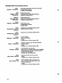
Compatible5700 Series Wireless Devices ............. ......... ......... ................. .......... ..................2l
Compatible5800 Sefies Mreless Devices ............................................................................22
VOLTAGE TRIGGERS (tinnmor J7) ............ ................... ... ...... ............................ ...................23
General information .... ...... ........ .. ............... .. ............... .. ................................ ...... .............23
Ground &ad Mdule . ......................... ......................... .... ................. .. ......... .. ...................23
Remote Keyswitch ............................................................................. ..............................24
Remote Console Sounder Operation ....................................................................................25
0UTPUTCONTROL(4204RelayModule/X-10 Devices) ........... ............................... ......................26
General ltiormation ........................................ ............ .......................... ........ ...................26
4204 Relay Module . ....................... .......... ................... ................... ............... .... ............. ..26
4300 Transformer & X-10 Devices .......................................................................................26
Examples Of Uses For Relay s............................................................................................27
REMoTEwNsoLEs
....... ............. ............ ...................................... ................... ...................3o
General ...... ................ ........... ........................... ....... .. ................... .......... .... ...................3o
4137m ............ .. ........... ........ .................................. .............. ........................................3o
5137AD ............ ..................... ........ .. ............... ......... ............................. ................... ......3o
6139 .. ............ ............. ........ ........................... ....... ......................................................3o
Prqramming The tinsoles .............. .......................... .................................... ...................3l
Mounting ~etinwles
........... .. .............................................................. ...... .......... .........3l
Wtingtinwles
............. .. ....... ................ ..................................................... .. ....... ..........3l
Poweting Additional Conales ................................... ...................................... ...................3l
EXTERNALSOUNDERS ........................................ .................. ......... ................... .......... .........32
Relay OutWt . .. .............. ............................................................................ .....................32
UL Household Installations ................................................................................................32
Non.ULlnstallations ............. ............. ..................... ...................................... ...................32
timpatibie Sounders ............ ...... ......... ......................................................... ........... ........32
PHONE wNNEcToNs
........................... ........ ..................... ........................ .. .......................32
-3-
Mounting ~eCabinet
Lo& .......... ................. ......... ...........................................................33
PrtmarylJower ........... .................................. ...................................................................34
Ba&.Up Power .......... ........ .......................... .......... ...................................... .. .................34
Earth Ground Connections ................................................. ............... ............. ...................34
Power-UpProcedu re... .......... ....................... ...................... .............. ....... ................. ........34
SEITING THE REAL-TIME CLOCK ............................................................................................36
●
SECURITYACCESS CQDES .................. ................................................. ................. ...............37
General Information ............................................................. ............ ................................37
User Codes & Levels Of Authority .......................................................................................37
Multiple Partition Access Examples .................... ................................ ................................39
To ADD a Master, Manager or Operator code .........................................................................4O
To CHANGE a Master, Manager or Operator code ......... ............................................ .......... ...41
To Deletea Master, ManagerorOperator de ... .......... .........................................................4l
To EXIT The User Code Entry Mode.....................................................................................4l
KEYPADFUNCTIONS ..... .. ............................... ... ................................... ..................... ...........42
General information .... .......................................... ........................... .... ............................42
Arming Functions ....... .................................. ........ ..................... ......................................42
A=esstintrol
.. ........ .. ........ ............... ......... .................................... ............ ...................~
Delay closing window ............................................ .................................................. .........~
Pa~ition "Goto"timmands ..................... ................................................ ..........................U
View Capabilities Of A User ................... ............ ................................ .............................. ..43
Viewing Downloaded Messages ..........................................................................................~
Using The Buik.ln User's Manual ............................................. ........... ................................~
Displaying Descriptors ............................. ...................................... .. ........................ ........44
Panic Keys ..... ...................................... ...... .... .............................................. .................44
Trouble Conditions ...........................................................................................................~
"Ch=k Messages ..... ............................... ... ................................... ................................U
OtherTrouble Conditions ............................ .................................... .. ................. ...............M
Power Failure .......... ................................................................................. ................ .......~
~EvENTLmGING ............ ........ ....... ...... ....................D................. .......... ................... .............45
Event Logging Printer Connections ..................................................... ................... .............45
Event kgging Procedures ................................................................ ................................46
Prqramming ............. ......... ........ ................. ................. ................... .......... .....................46
Event Logging Display & Print Modes ............... ................................... ............ ....................46
Clear Event Log ..... ........ ...... ........................ ............................. ...... ......... .. .....................47
Screen Definkions ...... ........................... ....... .......... ......................... ........... ................. ....47
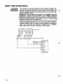
DIRECT WIRE Downloading
................................................................................................48
Spli~ual Re~tiing .... ............ ......................................................... ................................49
AdemmbwSpd
.............. .. ....... ..................................................................................49
SescotiRadionics ........................................ ............................... ....................................49
&2 Re~tiing ............ ............. ................ ..... ..................... ..............................................49
4+2 Express ....... ........................... ........................................................................ .........50
Ademm High Speed RepfliW .. ................. ................. .......... ................. ................. ...........5O
Contact ID Reporting ........................................................................................................5l
U:ing Test Mode .. ...... ........ .......................................................................... ......... ..........52
Armed System Test .... .. ................... ............................................ ....................................52
Turning The System OverTo~e User ............. ........................ .................................. .........53
DIP SWITCH TABLES .............................................................................................................56
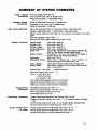
suMMmYoFsYsTEMmMANDs
......................................... .................................. ...... .. .....59
-4-
\
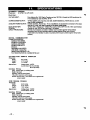
SUMMARY
General
OF SYSTEM
Information
FEATURES
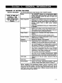
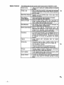
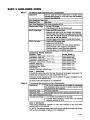
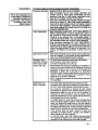
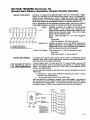
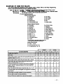
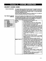
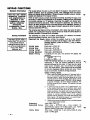
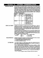
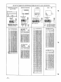
The following table lists the major features of the 4140XMPT2 system.
The 4140XMPT2 Control is a microprocessor based,
programmable, partitioned system, and features EEROM
memoty technology (power bss does not result in the
bss of information).
~ystem
NOTE: At least one
5137AD or 6139
addressable alpha
display console must
be used with this
system.
?ones Supported
Suppotts up to 9 traditional wired zones of protection.
Q Expandable to 87 zones (consisting of combinations of
wired and/or wireless zones) using 2-wire polling bop
devices, and/or 5700 or 5800 series wireless
transnltfers.
Zones oan be distributed among up to 8 bgioal partitions
of operation.
●
●
%e Zones
●
●
3utput Control
●
●
Remote Consoles
●
Keyswitch
Programming
Supports up to sixteen 2-wire smoke detectors (zone 1).
Other zones can be fire zones using 4-wire smoke and
heat detectors and/or polling loop detectors.
Supports up to 16 devices (4204 relay modules or X-1O
devices).
These devices can be put under schedule mntrol.
Supports up to sixteen addressable remote consoles
(6139, 5137AD, 4137AD).
Supports the Ademco 4146 keyswitch.
●
●
●
●
Programming can be performed at the office prior to
installation, or on the job site directly from the console.
Can be downloaded from a remote location or at the job
site (using a PC/laptop with 41OOSMSerial Module) by
using the Ademco 4130PC Downloading Software.
The Control is pre-programmed with a set of standard
values that is designed to meet the needs of many
installations. These values, however, can be changed to
suit the needs of any particular installation.
The Control can also be pre-programmed by the installer
with one of four standard communication default
programming values, thus further saving time and effort.
User Codes
Supports up to 128 user codes, maximum of 99 per
paftition
Panic Keys
Provides 3 panic key functions.
Communication
Ademco low speed, SESCOA/RADIONICS, Ademco
Express, Ademco High Speed, Ademco Contact ID
Before Installing this partitioned system, become completely familiar
with the partitioning concepts, including zone distribution (each zone can be
assigned to only one partition), user code usage and authority levels, and the
user-friendly menu mode of programming. In addition, become familiar with the
scheduling and output relay features.
-5-
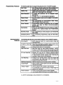
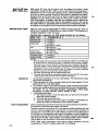
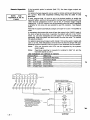
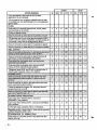
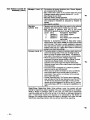
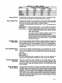
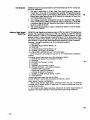
The following table lists the sDecial system features of the 4140XMPT2 svstem.
Global Arming
●
Polling Loop
●
Glass Break Detectol
●
Quick Bypass
(Forced 6ypaSS)
Memory-Of-Alarm
Circuit Breakers
●
●
Built-in polling loop interface, with polling loop terminals
located on the panel’s terminal block, allows expansion
up to 87 zones.
Supports up to 50 latching type 2-wire glass break
detectors on zone 8.
Quick (forced) bypass feature bypasses ail faulted
zones with single key entry sequence.
Memory-of-alarm feature, which, upon disarming the
system, automatically displays all zones that were in an
alarm condition while the system was armed.
“ Self resetting cirwit breaker protection eliminates the
need to replace blown cartridge fuses.
Built-in Users Manua
●
Descriptors
●
Cabinet
●
Scheduling
●
●
●
●
Wireless
●
Event Logging
●
Access Control
Allows users to easily arm multiple partitions via console
DromDts.
Built-in Users Manual (5137 AD/6139 onlv). Bv
depressing and holding any”of the function keys-on th~
console for 5 seconds, a brief explanation of that
function scrolls across the alpha-numeric display.
All programmed descriptors can be displayed (one at a
time) by pressing and holding the READY key for 5
seconds, then releasing the key. This serves as a check
for installers to be sure all descriptors are entered
properly.
Large cabinet
installations.
with
removable
door
for
easier
Scheduling feature allows installer and/or user to
automate system operation and/or turn on lights, etc.
Auto-arm/disarm of system.
Tempora~ schedules can be programmed by user.
System operation can be restricted to cerlain times.
Wireless suppoti of 5700 or 5800 series transmitters
using 4280, 4281 or 5881 type receivers.
Event Logging feature keeps record of all events, which
can be printed automatically or on demand.
“ Provides user activated access control command which
pulses a relay output for controlled opening of access
doors.
-4
-6-
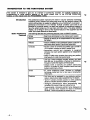
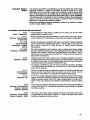
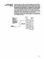
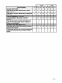
Programming
Poaturos
. ..
.
. . . .. . ..
.
.
. ..
User Codes
. Up to 128 user 8ecurity @e8
. . . . . .. . . . .
.
ln8taller Code
●
Alpha Descriptors
●
(maxt 99 per paftitbn) can
be programmed, each with varbu8 leve18 of authorfty.
Installer code override feature. Installer code will dbarm
system only if it was used to ann the system.
Aii zones and partitions can be assigned alpha
descriptions.
The ietter “s” or”’$” can be added to descriMors,
●
Custom Words
Up to 20 custom words can be added to the built-in
vooabularv,
●
I
Comm. Fieids
Easy programming for communication fieids, Simpiy
enter the reuml code for each zone.
●
I
Comm. Defauits
Downloading
Communication
Features
.
.-
Communication defauit programming can be ioaded
anytime, and does not affect non-communication
programfieids.
●
I
●
#93 Menu Mode
●
Scheduling Menus
●
Direct wire downloading can be done without a modem,
by using a PC or Laptop computer and 41OOSMSeriai
Moduie.
Easy programming of zones using the user friendiy #93
Menu Mode.
Easy scheduling programming using the #80 Menu
Mode.
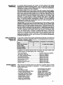
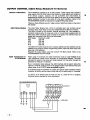
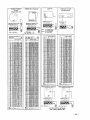
The foiiowing tabie iists the communication features of the 4140XMPT2 system.
Zone Reports
●
Exception Reporting
●
Aii 87 zones can report to a centrai station using any
reporting format.
Open/close reporting by exception means reports occur
only if outside predetermined
Caiiback
●
Reai-Time Cbck
●
time windows.
Caliback defeat option for downloading.
Reai-Time ciock for time reiated functions.
NOTE:
5137AD or 6139 aipha consoie must be used to set the
reai-time ciock, or can be set using Downloader software.
AC Loss Reporting
●
Test Reporting
●
Random AC Loss and AC Restore reporting option
sends report randomiy from 10-40 minutes after AC ioss,
to heip prevent centrai stations from receiving an
overioad of reports due to area biackouts.
Inteiiigent test reporting option means test reports wili
not be sent if any other report was sent within the
programmed test repod intervai.
Spiit/Duai Reporting “ SpliUDuai reporting communicator options avaiiabie.
Cancel Report
●
Voitage Triggers
●
●
Phone Numbers
Option to aliow a cancei report to be sent, even after Beil
Time-out has ended.
Used to interface with LORRA or other devices.
PC Downloader can command output voltage triggers to
puise on for 2 seconds.
Primary and secondary phone number capability.
“ Can program different formats for each phone number.
●
UL NOTE: Downloading is not permissible for UL installations.
-7-
This section IS Intended to aivo vou an overview of ~artitlonlna conce~te. For speelfic questions on
programming or using spe;iflc ‘aspects of the pa~el, pleae~ refsr ‘to the SYSTEM ‘OPERATION
section of this msnual snd the PROGRAMMING GUIDE.
Introduction
—.-
6asic
... .
.
Parmtionmg
Features
The partitioned system represents the latest in security protection technology.
Combining wired, wireless and polling loop zones into one powerful control, this
control communicator is capable of supporting a true “partitioned” environment. A
partitioned environment is one whereby multiple unrelated users wish to be
protected by a security system, yet each user requires the operational freedom to
have the system behave as if it was theirs and theirs alone. This global definition
imtMies a lot of thinas in terms of the required features of the equipment
you will
. .
install. Some basic f;atures are listed below:
-,. -.-,.,
–-.
,., -.. .– ... . .
Simple
●
Secure
●
.... . ..—--------
-.
.L–
.
.
.A”,
.m-l--
-..
_.-—
Easy to use and program as the simplest alarm system,
Integrity of security is not compromised for any users of
the svstem.
Reliable
“ Inherent reliability of the partitioned system is equal to a
stand alone alafi system-if purchased separately;
Consoies
c Flexible number of consoles per partition (up to a total of
16 in a system, an~ay you want to assign’them).
Appropriate sounds and messages to assigned
consoles only (each system appears to be independent
to users).
“ Ability to inhibit other consoles from using your partition
(total security in a strip mall environment).
●
User Codes
●
●
Zones
Partitions
“ 87 zones employing wired, wireless or multiplex
technology (install any mix for any type of construction
challenges).
●
●
●
●
-8-
128 User Codes assigned virtually anyway you want
them (99 max. in any partition, otherwise no restrictions).
Enough to handle the largest commercial jobs.
Multiple levels of authority per partition (allows key
people in a partition to have complete control and limit
system tampering by others).
Any zone can be assigned to any particular partition
(easy to install, allows logical assgnment by the dealer).
“GOTO function provides access to other partitions
(ideal for executive access to factory for example).
Intelligent partition/zone menu programming help
(simplifies the programming and reduces errors)
Programmable 4-character partition name displayed on
alpha consoles when needed (no need to memorize
numbers - name and number are shown for You).
Examnles Of
Partitlonlng
In survevirm dealers throughout the countrv, we have learned of two global
applicatibn;for partitioned %ontrol panels. ‘One is a typical two family fiouse
(residential), the other a Factory/Office environment. These broad classifications
can better be understood by way of examples.
Two Family House: You’ve just arrived at a job site to quote a security system.
The owner wants an alarm system which he can use for his family (living upstairs)
and he also wants to provide protection for the separate living quarters of his
mother (living downstairs with separate entrance). The owner obviously wants to
keep costs down yet provide protection and flexibility for his mother living
downstairs. You could choose to install a traditional alarm panel to keep costs
down, but the system woukf be very limiting for either the mother or the upstairs
family. To meet the flexibility requirements as desired, you could install two
traditional alarm panels, but the cost might cause you to lose the business. The
4140XMPT2 solves all these problems.
Factory/OffIce: You arrive at a small manufacturing concern boking to provide
protection throughout their offices as well as their factory. The very nature of the
business is such that factory workers come to work at 7:30AM and leave at 4PM,
while the offices are open 8:30AM to 6:OOPM.Some executives even want to
stay late at night or come back to work after 6:OOPM. Installing two panels (one for
the factory, one for the offices) would certainly work at a cost premium, but think
of all the complexity when owners tried to gain access to the factory after
hours...two access codes to remember, accidental false alarms. Even the real
frustration of not being able to properly program the two systems to allow easy
access from the factory to office or vice versa! Install a partitioned system, your
programming problems are over, and the owners of the business will appreciate
its flexibility and ease of use!
Global Partltlonlng
Features and
Resources
In any system, cefiain physical system components and features are shared by all
partitions or assigned to a specific partition. The following elements are shared or
assignable to a specific artition:
Shared By All Partitions Assignable To One Partition
Dialer
d
Alarm Relay/Sounder
# (using relay outputs)
d
Power Supply
d
Wireless Keypad
/
Keyswitch Station
/
In addition to the physical devices which are shared, the system shares some
software features on a global basis as well. These include:
Panic Code Reports .........................................Comnm code for any partition
Low Battery Reporting ......................................Repods as Partition 1
AC Power Reporting Options ............................Repofls as Partition 1
Test Reporting Interval .....................................Global for the Panel
Download Phone Number ................................Global forthe Panel
Communication Format .....................................Global forthe Panel
Rotary/Touch Tone ..........................................Global for the Panel
Download Callback defeat .................................Global for the Panel
Installer Code ...................................................Gbklfor all Partitions
Partition
Speclflc
Features
Many devices and functions need to be reserved on a partition basis to provide
proper operation and flexibility for installations. The items assignable on a per
partition basis include:
Consoles
QEntry and Exit Delays
s Console Sound during Exit Delay
Primary Subscriber Number
Secondary Subscriber Number
c Enable/Disable of Panic Keys
Enable/Disable of Duress
Multiple Alarm Reporting
s Quick Arm enable/disable
Inhibfl Bypass of one Zone
●
●
●
Enable/Disable Chime Mode
“Go To” Partition function
Swinger Suppression
Burglary Alarm Comm. Delay
c Open/close for Installer Code
Confirmation of Arming Ding
Alarm Sounder Duration
User Codes
●
●
●
●
●
●
●
●
●
●
-9-
Major Features Of
Scheduling
Scheduling is an exciting new feature of the 4140XMPT2 and provides the
following ftinctions.
Arm/Disarm control
Scheduling can be used to automate some of the system operation:
Auto arming and disarming at predetermined times.
Auto-arm warning
User option to delay auto arm
Provision for temporary schedule of up to one week
Provision for a holiday schedule
— Limitation of arming and disarming to specific times
Control of when disarming will occur
I
Open/close by exception
Scheduling provides a means of reporting openings/closings by exception:
sends report only if action does not occur.
— Inhibfl opening/closing reports if within a Time Window
— Send early to operVclose reports if done earlier than window
c Send late to open/close reports if window is missed.
Relay Control (Time Driven Events)
Scheduling can also automatically perform relay driven actions at predetermined
times:
— Can turn lights or other devices ordoff at specific times
One shot action of light or other device
— X-1Ocontrol for the automation of lights and appliances
Daylight Savings Time
— Automatic time adjustment for daylight savings time
Scheduled events are programmed using a user friendly menu mode of
programming (#80 mode), explained in detail in the separate PROGRAMMING
GUIDE. This menu programming takes you step by step through the options.
The following overview will give you an understanding of the scheduling
concepts. Refer to the PROGRAMMING GUIDE for detailed programming
instructions.
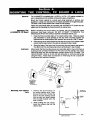
Access Door Control
The system also provides a means of access control. Entry of USER CODE+ O
will cause a momentary trigger of a pre-set output device. Each partition can have
its own output device. The trigger will occur on the device tied to the partition for
the console on which the keys were pressed. The access control relay is
programmed in partition-specific field 1’76.
Time-Driven
Event Programming
This very powerful feature allows arming, disarming, relay modules or X-1O
devices to be activated automatically, based on the time windows described
previously. Time driven events can also be used to assign additional open/close
window schedules, so that more than one schedule per day can be programmed.
The system supports up to 20 time driven events. Refer to the PROGRAMMING
GUIDE-Scheduling Programming for more detailed information.
The system provides up to 20 “timers” available to the end user for the purpose
of activating output devices at preset times and on preset days. These timers are
analogous to the individual appliance timers that might be purchased at a
department store. The typical uses for this feature could be control of lights or
appliances, typically via X-1Omodules. These modules are programmed into the
system by the installer during #93 Menu Mode-Device Programming. The end
user needs only to know the output device number (relay number) and its alpha
descriptor, both programmed by the installer via Relay Programming and Alpha
Programming respectively. To enter this mode, the user enters CODE+ # + 83.
End User Scheduling
(#83 Menu Mode)
The installer may set certain relays to be “Restricted”, since a system may have
some devices (Relays or X-1O)which are not intended to be under the control of
end users, such as relays activating fire doors or relays activating certain
machinery. This option, set during #93 Menu Mode-Relay Programming, will
restrict operation by the end user.
-1o-
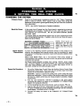
w
ZONE TYPES
& APPLICABLE
SENSORS
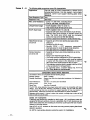
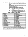
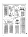
The 4140XMPT2 supports up to 87 zones of hard-wire, polling loop and/or
wireless protection, distributed among up to 8 partitions. The following table lists
the zone numbers and the types of sensors that can be used with each in this
system:
Sensors
one
1
2-wire smoke detectors (if used)
7
8
1-9
1-63
1-87
10-87
95
96
99
keyswitch (if used)
latching type glass break detectors (if used)
traditional hard-wired zones
5700 eeries wirelees devices
5800 series wireless devices
polling loop devices
“/1 panic
#13panic
●/# panic
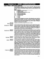
Each zone must be assigned to a zone type, which defines the way in which the
system responds to faults in that zone. In addition, there are three keypad
activated zones (PANIC keys, see note below) for each partition, a polling loop
supervision zone, and four RF supervisory zones, two for each RF Receiver
installed, Zone types are defined below.
Type 00
Zone Not Used
Type 01
Entry/Exit #1 Burglary.
Type 02
Entry/Exit #2 Burglary.
Program a zone with this zone type if the zone is not used,
This zone type provides entry delay whenever the zone is faulted if the control is
armed in the Away or Stay modes. When the panel is armed in the Instant or
Maximum modes, no entry delay is provided. Exit delay begins whenever the
control is armed, regardless of the arming mode selected. These delays are
programmable. This zone type is usually assigned to sensors or contacts on
doors through which primary entry and exit will take place.
This zone type provides a secondary entry delay whenever the zone is faulted if
the panel is armed in the Away and Stay modes. When the panel is armed in the
Instant or Maximum modes, no entry delay is provided. Secondary exit delay
begins whenever the control is armed, regardless of the arming mode selected.
These delays are programmable. This zone type is usually assigned to sensors or
mntacts on doors through which secondary entry and exit will take place, and
where more time might be needed to get to and from the console. Delay time must
be greater than Zone type 1. (Ex.: a garage, loading dock, or basement door)
Type 03
Burglary.
This zone type gives an instant alarm if the zone is faulted when the panel is
armed in the Away, Stay, Instant or Maximum modes. This zone type is usually
assigned to all sensors or contacts on exterior doors and windows.
Type 04
Interior, Follower.
This zone type gives a delayed alarm (using the programmed Entry/exit time) if
the Entry/Exit zone is faulted first. Otherwise this zone type gives an instant
alarm. This zone type is active when the panel is armed in the Away or maximum
Perimeter
Type 05
Trouble by Day/Alarm
by Night.
modes. Maximum mode eliminates the delay though. This zone type Is
bypassed automatically when the panel Is armed In the Stay or
Instant modes. This zone type is usually assigned to a zone covering an area
such as a foyer, lobby, or hallway through which one must pass upon entry (After
faulting the entry/exit zone to reach the console to disarm the system.) Since this
zone type is designed to provide an instant alarm if the entry/exit zone is not
violated first, it will protect an area in the event an intruder hides on the premises
prior to the system being armed, or gains access to the premises through an
unprotected area.
This zone type will give an instant alarm if faulted when armed in the Away, Stay,
Instant or Maximum (night) modes. During the disarmed state (day), the system
will provide a latched trouble sounding from the console (and a central station
report, if desired). This zone type is usually assigned to a zone which contains a
foil-protected door or window (such as in a store), or to a zone covering a
“sensitive” area such as a stock room, drug supply room, etc. This zone type can
also be used on a sensor or contact in an area where immediate notification of an
entry is desired.
-11-
Type 06
Alarm.
This zone type sends a report to the Central Station but provides no console
display or sounding. This zone type is usually assigned to a zone containing an
Emergency button.
Type 07
Audible Alarm.
This zone type sends a report to the Central Station, and provides an alarm sound
at the console, and an audible external alarm. This zone type is usually assigned
to a zone that has an Emergency button.
Type 08
Auxiliary
Alarm.
This zone type sends a report to Central Station and provides an alarm sound at
the console. (No beii output is provided). This zone type is usually
assigned to a zone containing a button for use in personal emergencies, or to a
zone containing monitoring devices such as water sensors, temperature sensors,
etc.
This zone type provides a fire alarm on short circuit and a trouble condition on
open circuit. The beil output will pulse when this zone type is faulted. This zone
type is always active and cannot be bypassed. This zone type can be
assigned to any wired zone, but oniy certain wireiess systems
zones.
24-hour
24-hour
Went
24-hour
Type 09
Supewised Fire. (No
Verification)
Type 10
w/Deiay.
This zone type gives entry delay (using the programmed entry time), if tripped
when the panel is armed in the Away mode. This zone type is also active during
maximum mode, but no delay is provided (alarms occur immediately if zone is
tripped). This zone type is bypassed when the panei is armed in the
Stay or instant modes. Delay begins whenever sensors in this zone are
violated, regardless of whether or not an entry/exit delay zone was tripped first.
Type 20
Arm-Stay*
This is a special purpose zone type used with 5800 series wireless pushbutton or
contact closure or opening, and which will result in arming the system in the STAY
mode when the zone is activated.
Type 21
Arm=Away*
This is a special purpose zone type used with 5800 series wireless pushbutton or
Type 22
Disarm’
This is a special purpose zone type used with 5800 series wireless pushbutton or
contact closure or opening, and which will result in disarming the system when
the zone is activated.
Type 23
No Aiarm Response
This zone type can be used on a zone when an output relay action is desired, but
with no accompanying alarm (ex. lobby door access).
interior
contact closure or opening, and which will result in arming the system in the
AWAY mode when the zone is activated.
●
Note that these zone types are not for use by 5700 series devices.
NOTE FOR PANiC KEYS
Keypad panic zones share the same zone response type for all 8 partitions, but
panics may be individually enabled for each partition.
iMPORTANT!
FAULT ANNUNCIATION
Polling loop and RF faults (zones 88-91 & 97) will repori as trouble conditions
only, and as such, should be assigned either zone type 00 if no annunciation is
desired, or zone type 05 if annunciation as trouble condition is desired. See
FAULT ANNUNCIATION notes in POLLING LOOP and WiRELESS EXPANSION
sections for more information.
-12-
BASIC 9 HARD-WIRED
Zone 1
ZONES
Tha
fnllatuinfi
tshla
m }mm a rivae
1~ *UUIW Uu$lll
Ila#
IAUCI
r I Iw Ivlwwl!
7nna
&wl IV
i
I
fiharaAnrieibe
WI mmUWLUI *s#J9wu.
Applications
Can be used for EOLR supervised or closed circuit
unsupewised devices. It is the only zone that supports
2-wire smoke detectors.
Zone Response Type: Any
Response Time
350 msec
Max. Zone Resistance 100 ohms, excluding EOLR
Unsupervised Usage
Cut red PCB jumper.
Only closed circuit devices can be used.
●
●
EOLR Supervised
s Leave red PCB jumper intact.
Supports both open circuit and closed circuit devices.
Connect open circuit device in parallel across the loop.
The 2,000 ohm EOLR must be connected across the
loop wires at the last device.
Connect closed circuit device in series with the loop.
Leave red PCB jumper intact.
Assgn zone type 09 (fire)
s Supports up to sixteen (16) 2-wire smoke detectors
Semnd CODE + OFF sequence momentarily
interrupts power to reset the smoke detectors.
See table below for compatible detectors.
●
●
●
EOLR Fire Zone:
●
●
●
●
Compatible Smoke Detectors
Detector Type
Device Model #
Photoelectric w/heat sensor, direct wire......................System Sensor 2300T
Photoelectric, direct wire ... ......................................System Sensor 2400
Photoelectric w/heat sensor, direct wire......................System Sensor 2400TH
Photoelectric w/B401B base .....................................System Sensor 2451
Photoelect. w/heat sensor & B401B base....................System Sensor 2451TH
Ionization, direct wire ........ .............. ........................System Sensor 1400
Ionization w/B401B base ... ......................................System Sensor 1451
Photoelectric duct detector
wA)H400 base .......................................................System Senmr2*l
Ionization duct detect. w/DH400 base ..................... ...System Sensor 1451DH
Zone 1 Advisories
If the EOLR is not at the end of the loop, the zone is not properly supervised. The
system may not respond to an open circuit within the zone.
The alarm current provided by this zone is sufficient to supporl operation of only
one detector in the alarmed state.
UL NOTE: EOLR are required for UL installations.
zone 9
The foliowina table summarizes zone 9 characteristics.
4
Applications
This zone is unsupervised and is suitable for monitoring
fast acting glass break sensors or vibration sensors when
orormammed for fast resoonse.
Response Type
Any type except fire
Normal (350 msec) or Fast (l Omsec)selected in field ●14.
Response Time
Max. Zone Resistance 300 ohms
Only closed circuit devices can be used.
Unsupervised Usage
Connect these devices in series with one another
between terminals 22 & 23.
●
●
Zone 9 Advlsorles
Avoid using mechanical magnetic or relay type contacts in this zone when
programmed for fast response.
UL NOTE: The interconnecting wires from zone 9 shall be no longer than 3 feet,
with no intervening walls or barriers for UL installations.
-13-
Zones
2-8
—
t_hefollowing table sur narizes zones 2-8 characteristics.
Applications
Can be used for EOLR supervised or closed circuit
unsupervised devices. Can also support 4-wire smoke
detectors. Zone 8 can support Iatchmg glass break
Zone Response Type ~
Response Time
Zones 1-7:300 ohms, excluding EOLR
Max. Zone Resistance
“ Zone 8: 100 ohms, excluding EOLR
●
Unsupewised Usage
EOLR disabled in field *41 (enter 1).
Only closed circuit devices can be used.
“ EOLR enabled in field “41 (enter O).
Supports both open circuit and closed circuit devices.
Connect open circuit devices in parallel across the
loop. The 2,000 ohm EOLR must be connected
across the loop wires et the last device.
s Connect closed circuit devices in series with the loop.
●
●
EOLR Supervised
●
●
Glass Break Devces
on Zone 8
Supports up to 50 2-wire latching type glass break
detectors.
Configure as EOLR zone
c Second CODE + OFF sequence momentarily
interrupts power to reset the glass break detectors.
“ See table below for compatible detectors.
●
●
Smoke Detectors
on Zones 2-8
. Supports as many 4-wire smoke detectors as can be
powered
. Assign zone response type 09 (fire).
. The zones must be configured for EOLR supervision.
. A normally-closed, momentary switch must be installed
in series with the power to the detectors in order to
allow reset of the smoke detectors after an alarm.
. The detectors must be wired in parallel, with the EOLR
at the last detector for full supervision.
. To supervise power, a System Sensor No. A77-716
EOL Relay Module is reco-mmended.
Compatible
Glass Break Detectors
Use detectors which are compatible with the following ratings:
5VDC - 13.8VDC
Standby Voltage:
Greater than 20k ohms (equivalent resistance of all detectors in
Standby Resistance:
parallel)
Less than 1.1k ohms (see note below)
Alarm Resistance:
Alarm Current:
2mA-10mA
Less than 6 seconds
Reset Time:
The IEI 735L series detectors have been tested and found to be compatible with these
ratings. Up to 50 IEI 735L detectors, connected in parallel, may be used (the alarm
current provided by this zone is sufficient to support operation of only one detector in
alarmed state). Follow the manufacturer’s recommendations on proper installation.
Detectors which exceed 1.1k ohms in alarm, but maintain a voltage drop in alarm of less
than 3.8 volts can also be used.
Zones 2-8 Advisories
If latching type devices are installed on both zones 1 & 8, and these zones are
assigned to different partitions, there is a possibility that, if both devices go into
alarm at the same time, the resetting of one device could cause the loss of alarm
memory in the other device.
Use of N.O. or N.C. contacts on the same zone may prevent proper glass break
detector operation.
UL NOTE: 4-wire smoke detectors cannot be used in UL installations.
-14-
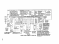
2-WIRE POLLING LOOP EXPANSION (Zones 10 through 87)
..-
...
. ..
1 11s
Iulwwll
.
. .. .. .
M
mule
.
.
aulillllarlLua
Applications
... ..––––
pu IIIf KI WUP
,––. ,–—.—–
.– .,-.,WWJW
IWUI
I w ial auw
IWUW
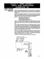
Built-in 2-wire polling loop interface allows the number of
zones to be expanded from the basic 9 zones to up to
87 zones using various Remote Point Modules (RPMs).
See ADVISORIES below.
The polling bop provides power to sensors and sewes
as comnnmication path between the panel and sensors.
“ Refer to the list of compatible devices at the end of this
section.
Each sensor must be assigned a unique address ID
number (from 10-87) before being connected to the
polling loop. Care must be taken to assign unique ID
numbers to each sensor in order to allow the panel to
supervise and provide console status indications for
individual sensors.
Most RPMs have DIP switches to set their addresses.
The 4139SN and 4191SN have preprogrammed serial
numbers which must be “learned” by the control via the
#93 menu programming mode.
●
●
RPM Address (ID)
●
●
Connections
●
●
●
●
Connect RPM sensors to terminals 24 & 25.
Sensors can be connected to a single run, or groups of
sensors may be connected to separate wire runs without
affecting the panel’s ability to supervise individual
sensors.
Follow the wiring instructions provided with individual
sensors. Be sure to obsewe sensor polarity when wiring.
The maximum allowable wire run length between the
panel and the last sensor on a given wire run is shown in
the table below.
Maximum Polling Loop Wire Runs
Note Twisted pair recommended for
Wire Guage Max. Length
all normal wire runs.
#22 gauge
650 feet
#20 gauge
#18 gauge
#16 gauge
950 feet
1500 feet
2400 feet
IMPORTANT: The maximum combined polling loop run is 4000’. If using
shielded wire, the maximum is 2000’. If longer wire runs are needed, a4197 Loop
Extender Module must be used (see instructions included with the 4197).
Intercom
Interference
If an intercom system is being used, the polling loop wires must be as far from the
intercom wiring as possible (minimum 6). If this spacing cannot be achieved,
shielded wire must be used. If this is not done, interference on the intercom
system might occur. Also note that the maximum total wire length supported is cut
in half when shielded wire is used.
Advisories
The built-in polling loop has two limitations that must be observed. First, the
maximum allowable current draw from the polling loop is 64mA. Refer to the
POLLING LOOP CURRENT DRAW WORKSHEET (found in the POWERING THE
SYSTEM section of this manual) for current draws of various polling loop devices.
Second, regardless of current draw, no more than 84 devices can be connected
to this loop. Installations which require up to 87 zones will require the use of
4190WH RPMs (which offer 2-points - a rght and a left loop - per device) or the
use of a 4197 (which offers another polling loop supporting an additional
64m/V64 points)
Make certain to include the total current drawn on the polling loop in the
AUXILIARY CURRENT DRAW WORKSHEET (see POWERING THE SYSTEM
section) when figuring the total auxiliary load on the panel’s power supply.
-15-
Important! Fault
Annunciation
Compatible
Since the polling loop and the RF receiver(s) are shared among the 8 partitions,
the scheme for annunciating their failure is as follows:
Respective faults (for zones 88-91 & 97) will report as trouble conditions only, and
as such, should be assigned either zone type 00 if no annunciation is desired, or
zone type 05 if annunciation as trouble condtiion is desired. If the polling loop or
RF link fails, the corresponding zone number will display a trouble condition for
each partition that uses the device that failed. In additiin, all zones associated with
that device will indicate a fault condition. The trouble condition will not interfere
with the ability to arm the partition, but the faults must first be bypassed.
Poiiing Loop Devices
4208
Eight Zone Poiling
Loop Expansion
Module
w
“ Used to supervise up to 8 hard-wired devices via the polling loop. NOTE: Does
not support 2-wire smoke detectors.
Set DIP switches to identify 8 zones.
The first two zones can be either normal or fast response (DIP switch selectable).
All zones are EOLR supervised (first six zones = 4.7k ohms, last two zones =
30k ohms), provided with the 4208.
●
●
●
4190WH
Two Zone Remote
Point Moduie
Used to supervise 2 hard-wired devices via the polling loop.
c DIP switch programmable.
The left zone can be EOLR supervised, if necessary, and can accept either
open or closed circuit sensors, and can be set for fast response. The right zone
is unsupervised and can accept closed circuit sensors only.
●
●
4278
Quad Element Poliing
LooP PIR
s Quad element PIR with built-in RPM which is DIP switch programmable and
connects directly to the polling loop. Includes mirrors for both wide angle and
curtain/long range applications. Features an auxiliary sensor loop that permits
connection of another nearby closed circuit alarm sensor (reed contact, etc.).
4275
Duai Eiement Polling
Loop PiR
4194
Surface Mounted Reed
Contact (Wide Gap)
4197
Polling Loop Extender
Moduie
c Dual element PIR with built-in RPM which is DIP switch programmable. Includes
mirrors for both wide angle and curtain/long range applications and can use the
1875PA Pet Alley mirror. Built-in selectable pulse count capability.
c Wide gap surface mounted reed contact with built-in RPM, which is DIP switch
programmable.
●
●
4192SD
Photoelectric
Poiling
Loop Smoke
Detector
4192SDT
Photoelectric
Poiling
Loop Smoke Detector
w/Heat Detector
4192CP
ionization Smoke
Detector
4139SN
Auto Smart Surface
Mount Reed Contact
4191SN
Auto Smart Recessed
Reed Contact
-16-
Can be used if the 2-wire polling loop must be greater than the recommended
length (4000’ max). By installing a 4197 at the end of the first loop, the polling
loop can be continued. If more than 64mA needs to be drawn from the polling
loop to power RPMs, use of the 4197 provides another loop with 64mA
available.
Connects to the polling loop and is powered from auxiliary power or by a
separate 729 power supply with battery backup.
“ One piece photoelectric smoke detector with built-in RPM which is DIP switch
programmable.
●
●
●
●
●
●
●
●
One piece photoelectric smoke detector with 1350F (57°C) heat detector, and
buitt-in RPM which is DIP switch programmable,
One piece products of combustion ionization detector with built-in RPM which is
DIP switch programmable.
Compact surface mount magnetic reed contact with built-in RPM.
Serial number ID “learned” by control panel.
Check product availability,
Recessed (1/2” dia.) magnetic reed contact with built-in RPM.
Serial number ID “learned” by control panel.
Check product availability.
~
\
RXPANSION (Zones 1=63)
WIR~LMS
Oonwal
Information
[Rooolvm’a)
I’he foliowlng tables
tones Supported
TransmJttcrs Supported
bv varloua rocolvers
71
Roe.ivor
4280
6%
rwnarizeswireless exBan8ion oharaoterlstios.
c The 8ystem supports up to 83 wireless transmitters
(5700 or 5800 series), plus a wireless keypad.
B To expand the system using wireless, one or two of the
same type of RF Reoelvers can be used.
~ Any zone from 1-83 can be used as a 5700 aerie8
wireless zone. The total number of trarwmlttere
SUPPCNW by each reoelver Is shown In the transmitted
supportedtable. Any zone from 1=87 can be used asa
5800 serieswirelesszone.
~FRsoeivers(Qenord
4281M
4281L
S881H
S881M
8
4
84
16
eQni
The 4140XMPT2 supports the 4280, 4281 and 5881
series RF reoelvere. Refer to the transmitters auppotted
ta:av:r
the number of zones supported by each
The receivers respond to status and alarm signals from
wkeleee transmitters (@345MHz USA; 315MHz Canada)
within a nominai range of 200 feet, and reiay this
information to the oontroi,
Two of the same type of receivers can be used to
provide either a greater area of coverage, or to provide
redundant protection, The type of receiver used is
identified in program field 1’32,
Receivers must be mounted externally to the controi,
The 4280 & 4280-8 receivers are connected to the
poliing loop.
The 4281 and 5881 series receivers are connected to
the consoie data iines.
if the connection is broken between the receiver and the
controi panel, a TROUBLE wili be dispiayed for zones 89
or 91 (if type 05 is assigned). in addition, aii zones
associated with the RF device will report a trouble
condition.
9
If, within a programmed intervai of time, the receiver does
not hear from any of its transmitters, a TROUBLE wiii
appear for zones 88 or 90 (if type 05 is assgned).
9
4280 oniy: if the cover of the 4280 is removed, a
TROUBLE wiil be dispiayed for zones 89 or 91 (if type 05
is assiqned).
Receivers respond oniy to transmitters set to the same
house iD (01-31). This prevents system interference
from transmitters in other nearby systems.
c Use Sniffer Mode (described later) to make sure you do
not choose a House ID that is in use in a nearby system.
4280 house ID is set via DiP switches.
4281/5881 (for 5827) house iD is programmed via #93
Menu Mode, Device Programming.
. To check for house iDs being used in nearby systems,
set the receiver’s House iD to “00”, then enter your
“Instailer Code”+ [#]+ [2]
9 The receiver will now “sniff” out any House iDs in the area
and display them. Keeping the receiver in this mode for
about 2 hours wiii give a good indication of the house IDs
being used. To exit the Sniffer Mode, simpiy key your
instailer code + OFF, then set your house iD to one not
dispiayed in the “Sniffer Mode”.
Important: Since Sniffer Mode effectively disabies RF
point reception, Sniffer Mode cannot be entered whiie
any partition is armed.
Receiver Supervision
●
House Identification
●
●
●
Sniffer Mode For
House Id
(Code + [#]+ [2])
●
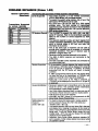
-17-
-..
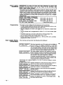
4280 8erles Receiver
4280 is not recommended
for new installation; receiver
is scheduled to be
discontinued.
–...
.. . . . .
. . . .. . .
..
.
.
4280 series
4281 series
Connects to polling
loop
Connects to
console lines
I1 5881 series
House ID
set via D1Pswitches programmed via #93
Menu Mode.
Receiver Address
Set by cutting blue
lumper in 2nd
receiver. Enabled
via fields 1“26 &
1●27.
Set via DIP
switches.Enabled
via #93 Device
Programming.
Set via DIP
switches. Enabled
via #93 Device
Programming.
Cover Removal
Causes alarm or
trouble depending
on response type
assigned.
Does-not cause
alarm or trouble.
Does not cause
alarm or trouble.
Go/NoGo Mode
Requires cover
removal.
Automatic upon
entering test mode.
Automatic upon
entering test mode.
Spatial Diversity
No. Requires 2
receivers for
redundancy or to
expand area of
coverage.
Yes. Eliminates
nulls and voids. 2nd
receiver expands
coverage area or
provides additional
redundancy.
Yes. Eliminates
nulls and voids. 2nd
receiver expands
coverage area or
provides additkmal
redundancy.
Transmitter ID
Set via DIP
switches.
Set via DIP
switches.
Serial numbers are
“learned” by the
system.
programmed via #93
Menu Mode.
.
lm~ortant: Note that if usirw two RF Receivers, one of them must be
powered from auxiliary power; so as not to exceed the 64mA polling loop
current rating.
. Set field 1*32 to O.
For more information regarding the 4280 installation, refer to the installation
instructions provided with the 4280.
If using a 4280-8, only up to 8 zones can be enabled as RF zones. If more than
8 zones are enabled, the message “SET-UP ERROR” (or E8 on non-alpha
consoles) will be displayed.
Refer to the maximum polling loop wire runs described in the POLLING LOOP
section when connecting 4280s to the polling loop.
IMPORTANT: The maximum combined polling loop run is 4000’. If using
shielded wire, the maximum is 2000.
-
●
✎
✎
4281 8erke
Receiver
✎
✎
✎
Set house ID via #93 Menu Mode.
●
Set receiver% device address using its DIP switches. Lower numbered
address is primary receiver (supervisory fault ID 90, 91). Higher numbered
address is secondary receiver (receiver fautt ID 88, 89).
Important: 4281 microprocessor must have part number N5334VX, where x is
any number. The microprocessor is located just above the DIP switch on the
PC board.
✎
5881 8eriee Receiver
Set field 1*32 to 1.
Using #93 Menu mode-Device Programming, select as RF device type.
●
✎
✎
●
Set field 1*32 to 2.
Using #93 Menu mode-Device Programming, select as RF device type.
Set house ID via #93 Menu Mode (needed for 5827 keypad only).
Set receivets device address using its DIP switches. Lower numbered
address is primary receiver (supervisory fault ID 90, 91). Higher numbered
address is secondary receiver (receiver fault ID 88, 89).
v
-18-
Transmitters
I
w
I Wllww
II
w LauIw
WJI I u Ilal Kwu
‘transmitters
(Generel)
●
‘rans. SupervWlon
:hecking Trans.
>peration including
)IP & serial number
Code + [#]+ [3])
●
●
●
●
‘Go/No Go” Test
ulode (Patented)
u
IaIaULWI
I=L*O.
Each transmitter (except 5701, 5727, 5802, 5802CP &
5803) is supervised by a check-in signal that is sent to
the receiver at 70-90 minute intervals. If at least one
Check-in is not received from a transmitter within a
programmed interval (field 1*31), the console will display
the transmitter number and “CHECK” will be displayed.
Each transmitter (including 5701; 5727, 5802, 5802CP
&5803) is also supervised for low battery conditions, and
will transmit a low battery signal to the receiver when the
battery has approximately 30 days of life remaining. The
console will display the transmitter number and “LO
BAT”.
●
●
;800 Series “Learn”
u m m IIILK71
Supports 5700 or 5800 series transmitters.
Each transmitter has its own unique transmitter ID
number (Zone #). 5700 series transmitters use DIP
switches to set the ID. 5800 series transmitters must
have their ID nurrbers “learned” by the system.
5700 series transmitters and the 5827 keypad must also
be set for a house ID. Other 5800 series transmitters
have built-in serial numbers and do not require a house
ID to be set. After installation, check that all transmitters
have been assigned the proper house ID by using the
procedure described later.
●
●
NOTE: After replacing a bw
or dead battery, activate the
transmitter and enter the
security code + OFF to clear
its memory of the “Low
Battery” signal.
wvu UIUW
5800 series transmitters have built-in serial numbers that
must be “learned” by the system during programming.
Refer to the PROGRAMMING GUIDE for details.
To check that all transmitters have been set property,
set the receiver to the proper house ID
and enter the Installer code + [#]+ [3].
All transmitters that have been enabled for the partition in
which the test was initiated will be displayed. As each
transmitter checks in (up to 2 hours), its ID number will
disappear. A faster way to do this is to fault each
transmitter, which causes a transmission to be sent to the
receiver. When all transmitters have checked in, there
should be no ID numbers displayed.
NOTE: Repeat this procedure for each parlition that uses
RF transmitters.
This mode helps determine the best location for each
transmitter and is activated by putting the control panel in
the TEST mode (4280 requires removing the its cover).
c The receiver’s sensitivity is reduced by half. Once
transmitters are placed in their desired locations and the
approximate length of wire to be run to sensors is
connected to the transmitter’s screw terminals, open
circuit each transmitter. Do not conduct this test with youf
hand wrapped around the transmitter.
If a single receiver is used, the console will beep three
times to indicate signal reception. If two receivers are
used, the console will beep once if the first receiver
received the signal, twice if the second receiver received
the sgnal and three times if both receivers heard the
signal (which is desirable for redundant configurations).
If the console does not beep, reorient or move the
transmitter to another location. Usually a few inches in
either direction is all that is required.
To exit this mode, enter the installer code and press
OFF (replace the 4280s cover). Note that the Receiver’s
sensitivity is fully restored when this mode is exited.
●
●
●
●
-19-
Note On RF Keys
(5801, S803, etc.)
Wirelees
Zone Types
5800 series RF keys can be used to arm and disarm the system. These
transmitters include the 5801, 5803, and any other 5800 series transmitter if
programmed for one of zone type responses 20-22. These transmitters are tied
to a user in order to provide a record of who armed or disarmed the system.
Because of this, an RF button will not armor disarm a system unless it has been
assigned to a user, which is done during the “add a user” function (see Add A
User Code section). In addition, when the user is deleted from the system, the
key is deactivated. To test whether the keys are assigned to users or not, use the
test mode. When the appropriate button is pressed, the corresponding zone will
be displayed on the console and will remain there until test mode is terminated.
,
w
Each RF zone can be programmed to respond as any zone type such as
ENTRY/EXIT, INTERIOR, PERIMETER, etc. (see the ZONE TYPES section for a
complete explanation of each zone type).
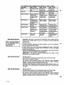
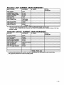
Desired alarm responses for 5700 series devices are as follows:
ZONE TYPE
TRANSMITTER ID #
Entry/Exit Burg
Perimeter Burg
Interior Burg
Fire
1 through 47 *
1 through 47
1 through 47
32 through 47 * (5775)
46 through 63
48 through 55 “’ (5706)
46 through 63*
62 or 63 ** (5701)
1 through 47
1 through 47 *
●
●
●
24 Hour Panic
(silent or audible)
Day/Night Burglary
24 Hour Auxiliary
NOTES:
Note that zones 1-63 can be used, but have the following limitations: Transmitters set
for zones 48-55 will transmit once every 12 seconds while the zone is faulted.
Transmitters set for zones 56-63 will transmit once every 3 seconds while faulted.
These two ranges of zone numbers could adversely affect transmitter battery life.
Transmitters set for an ID of 32 through 47 will have a 3 minute lock-out between
transmissions. Use this last range of zone ID numbers for sensors protecting
frequently used doors or windows to conserve battery life.
** Transmitter IDs 48 through 55 have highest signal priority.
*•* Transmitter IDs 62 and 63 are unsupervised to allow removal of the 5701 off premises
.- signal prioriiy is lower than that of fire, but higher than burglary.
●
●
●
Advlsorles
*
1. Do not place transmitters on or near metal objects. This will decrease range
and/or block transmissions.
2. Place the receiver in a high, centrally located area for best reception. Do not
place receiver on or near metal objects.
3. For maximum range, the RF receiver must be at least 10 feet from the Control
panel or any remote consoles to avoid intederence from their microprocessor.
UL NOTE: For UL Household Burglary Installations, wired loops
connected to these devices cannot exceed 3 feet.
4.
If dual receivers are used:
A. Both must be at least 10 feet from each other, as well as from the Control
panel and remote consoles.
B. The house IDs must be the same.
C. Using two Receivers does not increase the number of transmitters the
system can suppofi (83 transmitters, plus a wireless keypad).
Fault Annunciation
Since the polling loop and the RF receiver(s) are shared among the 8 partitions,
the scheme for annunciating their failure is as follows:
Respective faults (for zones 88-91 & 97) will report as trouble conditions only, and
as such, should be assigned either zone type 00 if no annunciation is desired, or
zone type 05 if annunciation as trouble condition is desired. If the polling loop or
RF link fails, the corresponding zone number will display a trouble condition for
each partition that uses the device that failed, In addition, all zones associated with
that device will indicate a fault condition. The trouble condition will not interfere
with the ability to arm the parlition, but the faults must first be bypassed.
NOTE: 5800 series transmitters have built-in tamper protection
annunciate as a “CHECK” condition unless field ●24 is disabled.
-20-
and will
~
Important
Battery
Notice
The wireless transmitters are designed to provide long battery life under normal
operating conditions. Longevity of batteries may be as much as 4-7 years
depending on the environment, usage, and the specific wireless device being
used. External factors such as humidity, high or low temperatures, as well as large
swings in temperature may all reduce the actual battety life in a given installatbn.
The wireless system can identify a true low battery situation, thus albwing the
dealer or user of the system time to arrange a change of battery and maintain
protection for that given point within the system.
Button type transmitters should be periodically tested by the installer for battery
life (5701, 5802, 5602CP & 5603).
Compatible
5700 Serlea Wireless Devices
Programmable for either silent or audible 24 hour alarm (can be DIP switch
5701
Panic Transmitter
programmed for zones 62 or 63).
Can be used with any cbsed circuit sensor. Can be used on any zone 1-63 but,
5711
if set for zones 3247, there wiil be a 3 minute lock-out between transmissions.
Sllmllne Door/Window
Transmitter
●
●
5711WM
Door/Window
Transmitter w/Fteed
Switch
Unlversai
5715WH
Transmitter
Wlreiess
5727
Keypad
●
●
●
●
5716
Door/Window
Transmitter
5775
Wireiess PiR
5706
Wireless Photoelectric
Smoke Detector
(System Sensor)
5707
Wlreiess Photoelectric
Smoke Detector (ESL)
●
●
Slimline door/window transmitter with built-in reed switch (magnet included).
Can be used with any closed circuit sensor. Can be used on any zone 1-63
but, if set for zones 32-47, there will be a 3 minute lock-out between
transmissions.
DIP switch selectable for fast response, open or closed circuit sensor usage,
and has a tamper protected cover. Use in applications where open circuit heat
detectors are needed or where fast response devices are needed. Can be
used on any zone 1-63 but, if set for zones 32-47, there will be a 3 minute bckout between transmissions.
Wireless keypad that can be used to turn the burglary protection on and off,
and features the same built-in panic functions as wired consoies for either silent
or audible 24 hour alarm. An LED indication lights each time a key is pressed to
verify transmission (LED located in the [Q] READY key).
The keypad is identified as zone “00” when it transmits low battery messages.
The keypad panics are identified in the same way as wired console keypad
panics (i.e. 95, 96& 99).
Can be used with any open or ciosed circuit sensor (DIP switch selectable), and
features a built-in reed switch. Can be used on any zone 1-63 but, if set for
zones 32-47, there wiil be a 3 minute lock-out between transmissions.
The 5775 is a battery operated, wireless, dual element passive infrared motion
detector with built-in selectable pulse count, that can be monitored by a 4280
(4280-8) wireless receiver, and is DIP switch programmable for zones 32-47.
NOTE: There is a 3 minute lock-out between transmissions to preserve battery
life.
c One piece smoke detector with built-in transmitter (DIP switch programmable for
zones 48-55). Built-in UL Listed 85 dB piezoelectric alarm sounder and audible
iow battery warning.
●
One piece, dual battery smoke detector with built-in transmitter (DIP switch
programmable for zones 48-55). Built-in UL Listed 85 dB piezoelectric alarm
sounder and audible low battery warning.
-21-
Campstlble
4=Button
5800 Berles WIrekee
5801
Transmitter
Devices
Four button hand held or wall mount transmitter.
s Programmable functions
Includes one 466 battery
●
●
5802
Pendant Panic
Transmitter
5802CP
Belt Clip Panic
Transmitter
3-Button
5803
Transmitter
Single button action
c Press and hokf to avoid accidental alarms
waterproof (sealed battery)
●
●
Single button action
Press and hold to avoid accidental alarms
“ waterproof (sealed battery)
●
●
Three button “key”
Programmable functions
Sealed battery
●
●
●
Photoelectric
5806
Smoke
Detector
Photoelectric
5807
Smoke
Detector
Mlnlature
5816
Transmitter
Includes two 9 votf alkaline batteries (464)
“ Optional tamper protection
●
Includes two 9 volt alkaline batteries (464)
●
s NO/NC Ui~bliiiy
●
●
3-Point
5817
Transmitter
Built-in reed contact
Tamper
Includes one 3 volt lithium battery (466)
Accepts 3 switches with 3 different addresses
NO/NC capability
Tamper
s Includes one 3 volt lithium battery (466)
●
●
●
Wireless
5827
Keypad
‘ Use handheld or wall mounted
Provides almost oornplete system control capability
c Raised dome keys and led for positive operation
●
●
●
5849
Giass Break Detector
No. 5634 belt clip available
Includes one 9 volt battery (464)
s Audio discriminator plus shock sensor
Tamper
Inoludes two 3 volt lithium batteries (466)
●
●
5890
Dual Element PIR
●
●
●
●
●
-22-
Interchangeable lenses: long range, etc.
Built-in transmitter with battery saver circuit
40’ wide angle pattern
Tamper
Includes two 3 volt lithium batteries (466)
VOLTAGE TRIGGERS (Connector J7)
(Ground Start Module, Keyswitch, Remote Console Sounder)
General
OUT
OUT
OUT
OUT
Information
!: GROUNO START OR OPENJCLOSE
2. FIRE OR KEYSWITCH ARMED LEO
3. BURGLAtW/AUOISLE
PANIc/AuxILIARY
4; SILENT PANICIOURESS OR KEYSWITCH
READY LEO
Connector J7, located on the right hand side of the main PCB provides 4 trigger
outputs for operating the 675 Ground Start Module, the 4146 Keyswitch, a
remote console sounding piezo, and for triggering auxiliary alarm signaling
equipment (such as the 7720 and 7920SE LORRA Subscriber Radios). Note that
these output triggers can be enabled by partition via programming field 2*20.
The pin assignments of this connector are shown below. Use only the 4142TR
9-wire cable (available as an option) for making connections to this connector,
output 1 Operates, by default, as a trigger for the 675 ground
This output may optionally be
start module.
J7 CUNNCCTON
programmed to operate as an operdclose trigger or as a
remote console sounder output. Only one of these
options may be used at any time.
Rating: When Activated: 10 -13.8 VDC through 4K
ohms
(2.5MA max)
When De-activated: 100 ohms to ground
outputs 2 & 4 Operate, by default, as Fire and Silent Panic/Duress
triggers respectively. These triggers may optionally be
programmed to act as Arm and Ready status indicators
when it is desired to use the 4146 keyswitch.
Output 2,3 &4 Rating:
Ground Start Module
Not intended for use In
UL Listed anplicatlons.
When Activated: 10- 13.8 VDC through 5K ohms
(2MA max)
When De-activated: 1k ohms to ground
An optional 675 Ground Start module can be used for installations having
telephone lines which require ground start instead of loop start operation to
obtain dial tone from the telco central office.
If used, program field 1●46 must be set to “O” (factory default) and the 675
Ground Starl Module must be connected to the panel’s J7 connector trigger
output 1, to auxiliary power, and to the “RING” side of the telephone line as
shown in the diagram below.
Use the following procedure to determine which side of the telephone line is the
“RING side:
a. Connect the “+” lead of a DC voltmeter to earth ground, and the “-” lead to
one side of the telephone line.
b. The wire which reads +50VDC is the “RING” side,
When the panel has a message to transmit to the central station, it will seize the
line, go off hook, and then trigger the 675 module to connect the “RING” side of
the telephone line to earth ground. The panel will cause the module to break the
connection between “RING” and earth ground when a dial tone is obtained.
4147TR CALIIJ
e
,
‘Q%+b
mTouNO START
TRIGGER
47$
OROuNo
STARRT
MODU..,, .
.17 C0NNEl,70n
1
Q+
71LUE
.
,
YELLOW
~
(CUT QUANGE
JUMPER)
—–—
BLACK
TO AUXPOWER
TERMINAL r
-
“+0
WHITE
-i+
$
‘:O:N
1) OUT 1 IS NO LONGER
USABLE FOR OPEWCLOSE
!SEE FIELD 1, 46).
2) OUT 2,3,4 CAN STILL BE
uSED TO PROVIDE ALARM
STATUS INDICATIONS OR
TO OPERATE A KEYSWITCH
(SEE FIELD 15).
3) THE 675 IS NOT UL LISTED
.
%.
l+#~::~g::;ORAw
To EARTH
GROUND
.
~40,
$
To TELCO
RING
:0”
GnAY
:
BROWN
.
Q90
%0
BLUE
%,
e
,
BLACK
m
Hi
-23-
Remote
Keyswitch
If the keyswitch
disabled.
option
is selected
(field ●15), the alarm trigger outputs
are
An optional Remote Keyswitch can be used for remote arming and disarming of
the system. Note that keyswitch arming may only be used in one
If used, program field ●15 must be set to the desired partition to enable the
‘artiti”n”
keyswitch option, and the4146 keyswitch’s normally open momentary switch and
LEDs must be connected to Zone 7 and to the J7 connector trigger outputs
respectively. A 2k EOL resistor must be connected across the switch regardless
of whether or not zones 2-8 are selected to use EOL resistors. See diagram
below.
Note that the system automatically assigns zone type 10 to zone 7 if keyswitch is
used.
A momentary short across this zone will arm the system in the “AWAY” mode. If
the short is held for more than 3 seconds, the system will arm in the “STAY”
mode. (i.e. all zones designated as zone types 4 or 10 will be automatically
bypassed). After the system has been armed, the next time zone 7 is shorted,
the system will disarm.
An optional closed-circuit tamper switch (model 112) can be wired in series with
zone 7, so that, if the switchplate is removed from the wall, the tamper wiil open,
disabling keyswitch operation until the system is next disarmed from the console.
Note:
Only one keyswitch with LEDs can be supported by the system’s
power supply.
Note:
Open/close reporting for keyswitch is enabled in field ’40, and the
keyswitch reports as user O.
LED indications are defined as follows:
Green Red
Meaning
off
Disarmed & Not Ready
off
On
Disarmed & Ready
off
Armed Away
off
On Steady
Armed Stay
off
Slow Flash
Rapid Flash
Alarm Memory
off
E
i
I
i
f
2
3A
I
567
~
*
I
8
9
BROKEN LINES REPRESENT
INSTALLER WIRING CONNECTIONS
m
—l——r
TO AUX POWER
TERMINAL 6
Ii
(
~--“-*
’20”1-
I
.—.
——
.—-—
—
—--—
-—
TAMPER
SWITCN IN. C.)
TO TERM. 20
IF KEYSWITCH IS USEO.
1] OUT 1 CAN STILL BE USED TO PROVIDE
GROuND START, OPENicLOsE {SEE FIELD I. 46}.
2) OUT 2,3,4 NO LONGER PROVIDE ALARM
STATUS lNOICATIONS
OUT 2 & 4 OPERATE
KEYsWITCH LEDs OUT 3 IS NOT USED.
ONLY 1 KEYSWITCH CAN BE USEO.
3) ZONE 7 IS NO LONGER USA6LE AS ,4
PROTECTIVE ZONE.
--—.
--
LOCK
SWITCH IN 0.)
TO ZONE 7 s
14
TO TERM
--—
63!
----
--
++---;
o
I
1---I
2000
OHMS
I
L------
1
-24-
I
I
19
-EOLR
$
1
4146 KEYSWITCH
(NOT UL LISTED)
Remote Console
Sounder Operation &
Wlrlng
An optional Amseco PAL 328N can be used for installations where it is desired to
remote the sounds produced by the console’s built-in piezo sounder for one
partition. The panel will remote all sounds (Le. alarm, trouble, chime, entry/exit,
etc.) produced by the console’s built-in sounder except for the short clicks
associated with console key depression. One applicatbn of this feature might be
to produce chime sounds in a bcation which is distant from the panel’s consoles.
This can also be accomplished using relay outputs (see Output Relay section).
If used, program field 1●46 must be set to “2” to enable the remote console
sounder option, and the Amseco piezo must be connected between the panel’s
auxiliary power and the J7 connector trigger output as shown below.
In addition, field ●15 must be used to select the partition whose console sounds
are to trigger the sounder. Zone 7 must be assigned to be a keyswitch zone
(even if keyswitch is not used).
414ZTU GAULE
IF USED,
1) ~:LUF~mLONQER
OPEN/CLDSEOR
QROUNDSTART (SEE
FIELD 1’46).
2) OUT 2,3,4 CAMSTILLBE
USEDTO PROVIOE
ALARMSTATUS iNDlCATIONSOR TO OPERATE
A KEYSWITCH(SEE
FIELO“16).
f15%A%ll
L?(ACK
—
d
+
EE13
YELLOW
~~
AMSEOOPAL-312SN
ER
PIEZOSOUNOE
r
TO AUX POWER+
TERMINALS
(lOmA CURRENTORAW)
J? CONNECTOR
—
~“IE
●
>
IIED
..
4
GREEN
-25-
OUTPUT CONTROL (4204 Relay Module/X-l
General
O Devices)
The 4140XMPT2 suppotts up to 16 relay outputs. These outputs may consist of
relay outputs from the 4204 output relay module (4 relay outputs per module) or
X-1 O device outputs. Outputs can be activated and deactivated by
predetermined events such as turning on lights in the event of an alarm condition
artdor closing a fire door in the event of a fire alarm condition. Refer to the
PROGRAMMING GUIDE for instructions on programming relay options.
Information
s
There are many different uses for relays, some of which are shown at the end of
this section.
4204
4300
Relay Module
The 4204 Relay Module has 4 form C (normally open and normally closed
contacts) relays. Each relay can be used independently for different functions.
The 4204 is wired to the control’s console terminals 6-9. Use standard 4conductor twisted cable (for long wire runs) or the connector supplied with the
4204. Each 4204 should be home run back to the panel, The maximum wire run
length from the panel to the 4204 must not exceed:
Wire Guage
Maximum Length
#22
125 feet
#20
200 feet
#18
300 feet
#16
500 feet
The 4204’s DIP switch must be set for a device address and that address must be
enabled in the control’s Device Programming mode. (Note that some early units
have only 4 DIP switches,)
Program the output relays using the control’s *93 Menu Mode. Refer to the
PROGRAMMING GUIDE for details,
Transformer &
X-1 O Devices
When using X-1O devices, the 4300 transformer must be used Instead of the
1361 transformer shown on the Summary of Connections diagram. The 4300
provides AC power to the panel and rela~s signals from the p=nel through the
premises AC wiring to X-1Odevices.
Run a 3-conductor cable between the 4300 interface and the panel. Splice this
cable to a 4142TR cable as shown in the diagram below. Note that the white and
yellow wires of the 4142TR must be spliced together.
X-1O devices plug into standard AC outlets and can be used to perform various
functions. Be sure to set the proper house and unit IDs when using X-1Odevices.
UL NOTE: X-1O devices and the 4300 are not UL Listed for fire or burglaty
functions and are intended for home automation.
DO TRANSFORMEWINTERFAC
J8 CONNECTOR
OJI
u
: Datn
C.xn
56
~
ml
-1
ml
40
ml
-2
Ii
I
I
I
-26-
4142TR CASLE
*
~XAMPLRS OF USES FOR RSLAYS
The followlng table Ilate examples of some possible usee for rolaym Refsr to the Relay Programming
section of the PROGRAMMING GUIDE for detailedInformation,
~18T OF START
AND STOP
~~~~i
&$klR9q0Wl”ld0ee
for2~2doMand9 hydoaad;
M40t Ueed;harm’ 2hUit;3=TroWle’4=ReetofQ
ZLmZON#LM
L18T,~-Milk.
CHOICES
2sPuieeonarldoff
1to8 tiFti*~l)wO=Nti-,
~@nwwddlm*m
ktimt@-lMmtiWSTA~
27 BZono7y@yMelll Operatfolr
OholeeeForZoneTypesAm:
00. NoReepofw
RE_Ed=E
02=24 Hr8Uent
07=24 HrAudibla
02=24 HrAux
0S9 pin
10= Mm&r w/Delay
01mEntrytaxit
03= Porknmr
04= InteriorFollow
02- TroubkDwAlamr Night
Ohofon Foreysternoperation;
20¤Arming-Stay
32= FireZorw7roubie
21= Atmlno-Away
22¤ Dlearmin2
31= EndofExitTime
32= Startof En8yThe
33= Any2urg@ Alarm
34=ooda+#+7+l
33= Code+#+7+2
40.ay~
33= At~li ‘f’iMOOUt’**
37.2 Times Bell Timeour”
*Chlm@
w w●
52.
41 = AC Pow Failure
42= Sy8WllhWyi.OW
42= OommuniodonFalluru
44. RFLowEatwry
46= PollingLoopFailure
61 = RF Receiver f%ih
Xiaaoff
34= FireZoneReset
Ss. ouluee
‘Should beuaedtoctwt2~d
doeeofru&yonty
●“Or at Diurming,Whioheveroooureearfier
Addltlond StopCholooe:
3S=Diaarm+l Mhwte
as= X%tdinutae(EnterXXat 1*74)
YYat1“7S)
67= WSeocndE(Enter
STOP
START
ACTION DESIRED
Close relay at start of entry time and reset with key entry of
seourity code+ # + 7+1
2
0
0
32
x
o
34
x
Close relay at start of entry time and reset after 1 minute
2
0
0
32
x
55
Close relay after any burglary alarm and reset with key
entry of security code + # + 7 + 2.**
2
0
0
33
x
o
o
35
x
x
2
0
0
00
x
o
35
x
Pulse light on trouble oondition to attract attention_
3
3
x
00
x
22
Puise Light on alarm to attract attention_
3
1
x
00
x
Use a PIR to turn a light on for a pre-set time period_
2
2
x
00
x
o
o
o
x
x
x
●
●*Can be used to turn on lights in the event of a burglary
alarm...(NOTE: Response types 06, 08, and 09 will not
activate relay).
Turn All Lights off with entry of security code+ # + 7 +2*
*Can be used to turn off all lights in on a given X- 10 House
and Unit Id
22
56
-27-
START
ACTION DESIRED
= You must define a Stati zone list (z/) for these
applications to work properly.
●Can be used to turn on lights in a specific room or area.
For example you can automatically turn on the basement
/ight on entry.
CHIME
Close relay for 2 seconds during chime. (Chime mode
1
must be turned on at control)
Chime on Specific zones:
gdri~i~qz~~i~;(%j
@W,~$&yfO~~,S~@$
~{g~~itiq~j
“Will activate relay for any zone type plus panics on 5601
$,i:::
..,,.,,,..
whether control is armed or disarmed. (Console panics will
not activate a relay with the configurations above.)
Zones in zone list (x) close relay for 2 seconds on alarms
1
Zones in zone list (x) close relay for 2 seconds on troubles
1
Close relay after any burglary alarm and reset at bell
timeout or when disarmed by any partition.
2
*Response types 06,08, and 09 wi// not activate re/ay. /f
PULSE relav is desired, enter a 3 in A(actionl.
Zones in zone list (x) pulse a relay after alarms and reset
when disarmed by either parltion.”
]3
I
Close relay when ARMED-AWAY, reset when
DISARMED. (Any partition)*
2
Close relay when ARMED-STAY, reset when DISARMED.
(Any ~artition)’
2
‘If PULSED relay is desired, enter a 3 in A(action).
Bypassing a zone causes relay to close and will reset with
a disarm sequence (code+ off.)
2
CONFIRMATION OF ARMING DING
I
Close relay for 2 seconds at end of exit delay time after
system is armed
I
28 -
1
START
ACTION DESIRED
STOP
A
EV
ZL
ZT
P
ZL
ZT
P
2
1
x
33
x
x
34
x
x
09
2
1
+#+7+1
,,,,,.,,,.,,,.
,.,,,.,.,.,.
,,,.
,,,,,.,,,.,,,,,
................ ............................................. ................................................................................
g~g
Mg: =% ~~
:%MRwMm;EMMM#MRwIMtMMxlMwHHmwm:
x
x
34
x
UNLOCK EXIT DOORS
Close relay on Burg alarm, reset with entry of security
00de+#+7+l
Close relay on Fire alarm, reset with entry of seourity code
An AC loss detection causes relay to close for 2
seconds.*
1
0
MM
0
41
x
“The re/ay wi// not reset on restora/ of /ow batte~ orAC
power. For this reason, using “close for 2 seoonds” in
A(action) is recommended.
........................................
;@@& g~g~m,
,‘:%gwMwMm#&iwEww#Rg#%m#RwM
::::.,,,.,.,
..........
.,,,,,,,,,,,.,.
.,,,..,,.,.,.
Pulse relay at start of entry time and reset when system is
3
0
0
disarmed (entry warning)’
jm%
m~
32
x
=$
;@@@ ~~$
...........}..
o
g~
o
00
x
m;
~~$
22
“Relay oan be used to turn on an external sounder placed
where it can be head by someone using the wireless
keypad.
-29-
x
General
The Control supplies up to 750 mA of auxiliary power for remote consoles, polling
loop devices and/or other auxiliary devices such as motion detectors or 4-wire
smoke detectors*.
The Controls support, independent of auxiliary power considerations, up to 16
addressable remote consoles (4137AD, 5137AD, 6139).
Up to twelve (12) 4137AD or eight (8) 5137AD or seven (7) 6139 consoles can
be powered from the auxiliary power output provided that the total current drawn
from this output does not exceed 750 mA. Keep this in mind when adding
remote consoles so you don’t overdraw current from the panel. This woukf result
in a battery which does not charge properly or possibly a tripped auxiliary solid
state circuit breaker.
If the auxiliary load is determined to be greater than 750 mA, then additional
consoles can be powered from a separate power supply. Refer to the
POWERING ADDITIONAL CONSOLES paragraph for a diagram that shows how
to make connections to the separate power supply.
4-wire smoke detectors cannot be used in UL Listed applications.
●
4137AD Addressable
Fixed-Word Console
Equipped with a liquid crystal display (LCD) using 2-digit numerics for zone
identification, and a set of pre-designated English language prompts, such as
“READY”, “NOT READY”, etc. for system status. Keys are backlit. A built-in alarm
sounder is also included, eliminating the need for a separate indoor sounder. DIP
switch selectable ID number, which allows console to display status of the
partition to which it is assigned. 60mA current draw.
5137AD Addressable
Alpha Console
Equipped with a programmable 2-Iine, 32-character (16 characters per line),
backlit alphanumeric LCD for complete zone identification in English language (if
descriptors are programmed). Keys are also backlit.
An alarm sounder is built in, eliminating the need for a separate indoor sounder.
DIP switch selectable ID number, which allows console to display status of the
partition to which it is assigned.
90mA current draw.
6139 Deluxe
Addressable Alpha
Console
The 6139 Remote Consoles are keypad addressable (no DIP switches) console,
and features a red “ARMED LED which lights when the system is anneal, and a
green “READY” LED* which lights when the system is ready to be armed (no
zone faults present). This console also features display backlighting. The keypad
on this console is located behind a decorative door, and is continuously backlit for
ease in use. The keypad also features special panic keys, labeled A, B, & C (the
D key is not used), which are the equivalent to the panic pairs of keys l/Q, Q/#, &
3/# respectively. Note that these keys must be held down for at least 2 seconds
to activate an alarm.
* Note that the function of this LED (system ready)differs from the function of the
green LED on Ademco’s4137AD & 5137AD consoles.
The console can be surface mounted directly to a drywall, or to a single or double
gang electrical box. For flush mounting to drywall, use the optional6139TRK
flush mount kit.
100mA current draw.
-30-
-
Programming The
Consoies
Mounting The
Consoies
Wiring
Consoies
The consoles can beset for an address of 0-30
iMPORTANT! You must select an address of O, 1, 2, or 3 if standard defaults
are to be programmed, since these are the only console addresses enabled by
the standard default. Refer to the addressable console DIP switch table at the
end of this manual to set the 4137AD and 5137AD address ID number. Refer to
the instructions provided with the 6139 to set its ID number.
Do not use address 31 with the 4140XMPT2. Address 31 causes the
console to operate in non-addressable mode (i.e. works like a standard, nonaddressable console).
Consoles must also be programmed for type, partition number and console
sounder suppression options. Refer to the PROGRAMMING GUIDE (#93 MENU
MODE-DEVICE PROGRAMMING) for instructions.
Note that fiekf wiring to the consoles must be completed before the consoles can
be mounted.
The consoles can be either surface mounted or flush mounted (using an
appropriate Trim Ring Kit: 5137TRK or 6139TRK). Refer to the mounting
instructions and template included with the console and/or trim ring kti for specific
information.
Be sure to take the height of the users into account when mounting consoles.
Consoles may be wired to a single wire run or individual consoles may be
connected to separate wire runs. The maximum wire run length from the panel to
a console which is homerun back to the panel must not exceed:
NOTE:Thelengthof all wiremnsoombinadmustnot
Wire Guage Maximum Length
#22gauge
#20gauge
#18gauge
#16gauge
Powering
Additional
Consoies
450 feet
700 feet
1100feet
1750feet
excsad2000feetwhenunshielded
quadconductor
oabls
isused(1OCO
faatifshieldadtie isused.)
If morethan one consoleis wired to a run, thenthe
abovemaximumlengthsmustbedvkfad thenumber
of consoleson therun (i.e.themaximumen
Y! th would
be 225 feet if two oonsolasarewiredon a # 2 gauge
Nn),
Up to twelve 4137AD or eight (8) 5137AD or seven (7) 6139 consoles can be
powered from the auxiliafy power output provided that the 750mA rating is not
exceeded. The backup battery will supply power to these consoles in the event
that AC power is lost.
Additional consoles can be connected to the system by using a regulated,
12VDC power supply (eg. 487-12 supplies 12V, 250mA; 488-12 supplies 12V,
500mA). Use a UL Listed, battery backed supply for UL installations. Note that the
maximum number of consoles supported by the system is 16.
Connect additional consoles as shown below, using the console wire colors
shown. Make sure to observe the current ratings for the power supply used.
Wire run lengths from the 4140XMPT2 to consoles are listed in the WIRING
CONSOLES paragraph (maximum combined wire run lengths for all consoles
must not exceed 2000, or 1000 if shielded cable is used).
IMPORTANT: Make connections directly to the screw terminals as shown. Make
no connection to the wnsole blue wire.
The 487-1 2/488-1 2 power supplies have a backup battery which can power
these consoles in the event of AC power loss. Note that consoles powered from
supplies which do not have a backup battery will not function when AC power
is lost. In this case, make sure to power at least one console from the Control’s
auxiliary power output.
-31-
EXTERNAL
SOUNDERS
Relay Output
UL Household
Installations
Non-UL
Installations
Sounders
702
Outdoor Siren (not UL
Listed)
The Control provides a wet beli relay output which is used to power externai aiarm
sounders. Connections are made to terminais 4 (positive output) and 5 (negative
return). See SUMMARY OF CONNECTIONS Diagram.
-
For installations which must provide (JL Listed protection, the total wrrent drawn
from this output and the auxiliary power output, combined, must not exceed
750mA in order to wmply with the battery independence requirements. if two
System Sensor PA400 piezo alarm sounders, wired in parallel, are used (24mA
total),then (750MA - 24mA=) 726MA is available for auxiliary output use.
For non-UL installations, the total current drawn from this output can be up to 2.8
amps. A battery must be installed since current in excess of 750mA is suppiied by
the battery. Up to two 702 sirens can be used, wired in series. Up to two 719
sirens can be used wired in parailel.
iMPORTANT: Going beyond the above mentioned limits will overload the
power supply or may possibly trip the beli output cirwit protector.
Compatible
719
Compact Outdoor
Siren (not UL Listed)
740
High intensity Sounder
indoor
747
Siren
ABB1031
Motor Beii & Box
PA400B
(beige)/PA400R
(red)
indoor Piezo Sounder
●
●
Self-contained siren (driver built-in) and weatherprmf for outdoor use. Can be
wired for either a steady or yeip sound and is rated at 120 dB @ 10 feet. This
siren can also be tamper protected, or can be mounted in a metal cabinet (716),
which can be tamper protected.
Compact, self-contained siren (driver buiit-in), and weatherproof for outdoor
use. Can be wired for either a steady or yelp sound, and is rated at 90 dB @ 10
feet. A 708BE cabinet is available, which can be tamper protected if necessary.
●
Compact high intensity sounder rated at 123 dB @ 10 feet. This sounder emits
an ‘ear piercing”, high frequency sound. Th”~ sounder can be mounted indoors
(bracket included) or outdoors (in 708BE cabinet).
Attractive, self-contained indoor siren (driver built-in), provides steady or warble
tones and is rated at 95dB @ 10 feet.
AMSECO motor bell& box, rated at 81 dB @ 10 feet.
●
System Sensor indoor piezo sounder (red or beige), rated at 90 dB @ 10 feet.
●
●
UL NOTE: Use only UL Listed sounding devices for UL installations.
PHONE CONNECTIONS
Phone Line
Connections
incoming phone tine and handset wiring is connected to the main terminai biock
as follows (refer to SUMMARY OF CONNECTIONS Diagram):
TB1-26: Local Handset (TIP)
TB1-27: Local Handset (RING)
TB1-28: Incoming Phone Line (TIP)
Warning
PABX
-32-
TB1-29: IncomingPhoneLine(RING)
If it is desired to connect the panel to phone lines that require ground statl
capability, then a 675 Ground Start Module must be used. This moduie is
trggered by one of the outputs on the connector Iabeied J7 (see VOLTAGE
TRIGGERS section).
To prevent the risk of shock, disconnect phone lines at teica jack before servicing
the panel.
If the communicator is oonnected to a telephone line inside a PABX, be sure the
PABX has a back-up power supply that can support the PABX for 24 hours. Many
PABXS are not power backed up and connection to such a PABX wili result in a
communication failure if power is lost.
k
The 4140XMPT2 is supplied with a 12.5”W x 14.5”H x 3“D cabinet suitable for
use in residential and non-cedified commercial burglary installations.
Mount the Control cabinet to a sturdy wall using fasteners or anchors (not
supplied) in a clean, dry area which is not readily accessible to the general public.
The back of the Control cabinet has 4 holes for this purpose.
Follow the instructions below for mounting the 4140XMPT2 PC board into the
cabinet and for mounting the Control’s lock to its cabinet door.
General
Mounting The
4140XMPT2
PC Board
Before mounting the circuit board, be certain that the appropriate metal
knockouts have been removed. DO NOT ATTEMPT TO REMOVE THE
KNOCKOUTS A~ER THE CIRCUIT BOARD HAS BEEN INSTALLED.
1, Hang the three mounting clips on the raised cabinet tabs. Observe proper
clip orientation to avoid damage to the clip when mounting screws are
tightened and to avoid problems with insertion and removal of the PC board.
2. Insert the top of the circuit board into the slots at the top of the cabinet, Make
cefiain that the board rests in the slots as indicated in step 2 detail.
Swina the base of the board into the mountina clim and secure the board to
the ~binet with the accompanying screws (as~llu~rated in step 3 detail).
Make certain that the mounting screws are reasonably tight to insure that there is
a good ground connection between the PC board and the cabinet. Also, dress
field wiring away from the microprocessor (center) section of the PC board. The
cabinet provides 2 loops on its left and right sidewalls for anchoring field wiring
using tie wraps. These steps are important to minimizing the risk of panel RF
inte~erence with television reception .-
3.
Advisory
Slw
a
—
f--=%Y//
A
“’cY’
8
@
DETAIL SIDE MEW OF
CLIP lNSTALLAnC+(
b. CAOINEl TAB
WITHOUT CLIP
0.CAWNW TAB
wm MN01N13 cL*
DETAIL SIDE VIEW
OF CLIP ANLI BOARD
INSTALLED
Mounting
The Cabinet
Lock
1. Remove the lock knockout on
the control cabinet cover, Insert
the key into the lock. Position the
lock in the hole making certain
that the latch will make contact
with the latch bracket when the
door is closed.
2, While holding the lock steady,
insert the retainer clip into the
retainer slots.
.m#mcw_
I
RETAINER CUP
‘@
*
...
..
a T
(,0
LOCKED
REIuNER
S1.ols
:
-..
““””\
UNLOCKED
-33c.AwNEl
OcoFl Ea-mM
Primary
Power
Power to the Control panel is supplied by model No. 1361 Plug-in Transformer
which is rated at 16.5VAC, 40VA. Caution must be taken when wiring this
transformer to the panel to guard against blowing the fuse inside the transformer
(non-replaceable).
●
‘ NOTE: Use 1361CN Transformer in Canadian installations.
Back-Up
Power
In the event of an AC power loss, the Control panel is supported by a back-up,
rechargeable gel cell battery. YUASA NP4-12 (12V, 4AH) and NP7-12 (12V,
7AH) batteries are recommended.
Do not use Gates batteries (sealed
lead-acid
type).
The standby battery is automatically tested every 24 hours, beginning 24 hours
after exiting programming mode. In addition, entry into the test mode will cause a
battery test to be initiated.
BATTERY
STANDBY
AMP-HRS. “200mA 400mA
~
Earth Ground
Connections
Power-Up
Procedure
NOTE:
TABLE
600mA
These figures are
750mA
!g~%~~~
In order for the lightning transient protective devices in this product to be
effective, the designated earlh ground terminal, must be terminated in a good
earth ground. The following are examples of good eaflh grounds available at most
installations:
Metal Cold Water Pipe: Use a non-corrosive metal strap (copper is
recommended) firmly secured to the pipe to which the ground lead is electrically
connected and secured.
AC Power Outlet Ground: Available from 3-prong, 120VAC, power outlets
only. To test the integrity of the ground terminal, use a three-wire circuit tester
with neon lamp indicators, such as the UL-Listed Ideal Model 61-035, or
equivalent, available at most electrical supply stores.
1. Fill out the Polling Loop Current Draw and Auxiliary Device Current Draw
Worksheets shown below. Make sure that the currents drawn from these
outputs do not exceed their respective ratings.
CAUTION:
Failure to observe the polling loop current rating will cause
polling loop malfunction. Failure to observe the auxiliary output current rating
2.
will result in a battery which does not charge properly or possibly a tripped
circuit breaker.
Wire the 1361 transformer
(1361 CN in Canada) to the panel (before
connecting the battery) as shown in the SUMMARY OF CONNECTIONS
diagram. Do not plug in at this time.
3. Connect all polling loop and auxiliary devices, such as consoles, PIRs, etc.
4. Plug the 1361 into an 24 hour, uninterrupted AC outlet. After a few seconds,
the green POWER LED on the console(s) should light and the console(s)
should display “DISARMED READY TO ARM.”
5. Connect the battery as shown in the SUMMARY OF CONNECTIONS
diagram.
-34-
w
POLLING
LOOP CURRENT DRAW WORKSHEET
RPM DEVICE
CURRENT
# UNITS
TOTAL
CURRENT
4194 Contact
4192SD Photo Smoke
4192SDT Smoke w/Heat
4192CP Ion Smoke
4275 Dual PIR
4278 Quad PIR
4190 2-Zone RPM
lmA
0.4 mA
0.4 mA
0.4 MA
lMA
lrnA
1 MA (LOW)
2 MA (HIGH)
4208 8-Zone RPM
16mA
428063 Zone RF
40 mA
4280-88 Zone RF
40 mA
TOTAL **
* If the total current draw exceeds 64 MA, a 4197 Loop Extender module must be used.
* If using two 4280s or 4280-8s, you can power one of them from auxitiary power instead of using a 4197 bop
extender module.
●
●
AUXILIARY
DEVICE CURRENT DRAW WORKSHEET
ID EVICE
4137AD Console
5137AD Console
6139 Console
675 Ground Start Module
4280 or 4280-8 Receiver
Built-in Pollinq LooP
4281 RF Receiver
5881 RF Receiver
4197 Poll Loop Extender
i CURRENT
I # UNITS
I TOTAL
CURRENT
I
60mA
90 mA
100mA
50 mA
40 mA
worksht)
(totalp II1001)
35mA
50mA
80 mA
●
●
●
TOTAL (750mA max)
If using hard-wire devices such as PIRs, refer to the specifications for that particular unit’s current draw.
— Only applies if powered from Control’s auxiliary power.
●
-35-
PROCEDURE
m
-36-
1
NOTE: A 5137AD or 6139 alpha console must be used to set the real-time clock,
or the clock can be set via the Downbader software. Only users with installer or
master authority level can set the real-time clock,
To enter real-time clock mode, enter installer or master code + #63.
typical display will show:
A
I TIM13DATE THU ~
01/01/90 I
~12:01 AM
The day of the week is automatically calculated based on the date entered. Time
and date entries are made by simply entering the appropriate hour, minute,
month, day and year. Pressing the ~] key accepts the entered value and moves
the cursor to the right. Pressing the [#] key moves the cursor to the left of the
display, to the prevbus position.
To set the time and date, simply enter the correct hour then press ~] to
move to the minutes and make the correct entry.
Press ~1 again, then toggle the AM/PM by pressing any key O-9.
Press ~] to move cursor to the month position and enter the correct month using
a 2digit entry.
Press ~] and enter the correct date.
Press [*] and enter the correct year.
To exit clock mode, press the ~] key after the cursor is in the year position.
w
.
@
O“*AO
●
SECURITY ACCESS CODES
General
Information
User Codes & Levels Of
Authority
●
Level
o
1
Title
Instailer
Master
The System aiiows up to 128 security acoess codes to be assigned (maximum 99
per partition), each identified by a user iD number. in addition, the Quick Arm
feature can aiso be programmed, wh@ enabies the [#] key to be pressed instead
of entering the security code when arming the system. The code must stili be
entered when disarming the system.
Note that Open/Cbse reporting of Quiok Arm is enabied if User 2 is enabied for
Open/Ciose reporiing, and that Quick Arm reports as User O.
Each user of the system can be assigned various Ieveis of authority (tells system
what system functions that user is authorized to do), and can have different ieveis
of authority within each parlition. Use the “View Capabilities” keypad funotion to
view the partitions and authority Ieveis for which a particular user ~Sauthorized. In
highest to lowest ranking, these ieveis are described below.
nstaller
Level O)
Jser 1
“ Programmedin field●OO(defautt=4-14-O).
Can be changedby installer.
Can perform aii system functions (arm, disarm, bypass,
etc.) and is the oniy user that can enter program mode.
Oniy code that aiiows entry to program mode.
s instailer code iockout if exit program mode via ’98. This
prevents instaiier from reaccessing program mode. The
only way to access Programming mode once this feature
is activated, is by powering down the system and
powering up again, and then pressing both the and #
keys at the same time within 30 seconds of power up.
The instaiier must program at ieast one master
code. Master codes are the codes intended for use by
the primary users of the system.
Can add, deiete, or change master, manager, or operator
codes.
Can select open/close reports for any user.
Can perform normai system functions, but cannot
disarm if armed by a code other than Instalier’s code
(inoluding Quick Arm).
Enable open/ciose reporting for instailer in field ●39.
●
●
●
●
●
●
●
●
Master (Levei 1)
The Master Code is the code intended for use by the
primary users of the system when performing system
functions, and oan be changed by the Master User.
The master codes can be used to assign up to 99 lower
level codes, which can be used by other users of the
system who don’t have a need to know the master code.
As shipped from the factory, there are no master or
manager codes pre-programmed. The installer must
program at ieast one master code during initiai
instailation.
Master cannot assgn anybody a ievel of Oor 1.
Can change his own code.
Can add, delete, change manager or operator codes.
Each user’s code can be individually eliminated or
changed at any time.
s Open/close reporting of added users are same as that
of the master or manager adding the new user.
Can perform ali system functions.
●
●
●
●
●
●
●
-37-
Ueer Codes & Levels Of
Authority (cont.)
danager (Level
Can perform all system functions (Arm, Disarm, Bypass,
etc.) programmed by Master.
c May create other users of the system below this level
(Manager cannot assign anybody a level of 0,1, or 2).
May change his own code.
May add, delete, change operators.
‘ Open/close reporting of added users will be same as his
own (enabled or disabled as assigned by installer or
master).
May operate a pattition.
lperator
Operators can arm and disarm the system to the authority
Levels 3-5)
assigned, but cannot add or modify any user code.
“ May operate a partition with one of the three
OPERATOR authority levels A through C listed below.
Level
Title
Functions
Permitted
Ann, Disarm, Bypass
Operator A
Arm, Disarm
:
Operator B
Arm, Disarm only if armed with
5
Operator C
same code
Operator C (sometimes known as Baby-sitter code),
cannot disarm the system unless the system was armed
with that code. This code is usually assigned to persons
who may have the need to arm and disarm the system at
specific times only (ex. a baby-sitter needs to control the
system only when baby-sitting).
)uress (Level 6)
The duress code is a means of sending a silent alarm to a
central monitoring station if the user is being forced to
disarm (or arm) the system under threat. This feature is
only useful if the system is connected to a central station.
When the system’s Auxiliary Voltage Triggers are
connected to another communication’s media (Derived
Channel/Long Range Radio), note that duress is
signaled on the same trigger that signals silent panic
(whereas duress has its own unique report when digitally
communicated).
The duress code is assigned on a pattition by pafiition
basis and can be any code desired.
When used, the system will disarm (or arm), but will also
send a silent alarm to the central station (if service is
connected). There will be no indication at the console
that an alarm was sent..
Duress Reporting Note: The Duress report triggering
logic activates on the 5th key depression (such as OFF),
not the 4th key depression (last digit of code). Duress
reports will not be triggered if the 5th key is a ~], such as
when performing a GOTO or viewing the capabilities of a
user.
2} w
●
●
●
●
●
●
●
●
●
●
Dpen/Close Reporting Note: When adding a user, the system will only
prompt for Open/Close reporl capability if the user is being added by the Installer.
When a Master or Manager adds a new user, the new user’s Open/Close
reporting enable will be the same as that of the Master or Manager adding the
user. If Open/Close reports are required to be selectable by the Master or
Manager, the Installer should assign two Master or Manager user codes: one with
Open/Close reporting enabled, and one without Open/Close reporting.
-38-
General Rules on Authority Levels and changes
The folfowing rules apply to users when making modfiications within the system
based on the user oode authority levels:
Master Codes and all lower level codes can be used interchangeably when
performing system functions within a partition (a system armed with a user%
temporary code can be disarmed with the Master Code or another usets
temporary code), except the Operator Level C Code described above.
A user may not delete or change the user code of the SAME or HIGHER
authority than wh~h he is assigned.
c A user (levels O, 1 & 2 onfy) may only ADD users to a LOWER authority level.
A user may assign other users access to only those partitions to which he
himself has access.
A user can only be DELETED or CHANGED from within the partition he is
assigned.
User numbers must be entered as 2digit entries. Single digit user numbers
must, therefore, always be preceded by a “O” (example, 03, 04, 05, etc.). Make
sure the end user understands this requirement. Temporary codes are entered
as 4-digit numbers.
●
●
●
●
●
Important !: Unless Ademco Contact ID reporting is used, only user codes #1 #15 can uniquely report to the central station using the communication formats
provided. Users #16 - #99 will report as User #15, if enabled for open/close
reporting, for the other reporting formats.
Multlple Partition
Access Examples
(GOTO Function)
To make a partitioned environment particularly useful, the system must allow for
certain people to have access to other partitions. This is particularly true in the
Factory/Office environment where the president of the company wants access to
any area of his company. The 4140XMPT2 has total flexibility in supporting this
requirement. On a USER basis, each user is programmed for a base partition (the
one he normally is assigned) and one or more partitions which he can be
authorized to access.
In addition, within each partition, each USER may be programmed to have
different levels of authority. For example, User #3, the V.P. of Engineering,
could be assigned to work within the Engineering Department (Partition 1) of
ABC Manufacturing. Since he needs the full capabilities in his area, he is
assgned as a MASTER with Level 1 authority. This means he may Arm, Disarm,
Bypass, Add or Modify users in partition 1. It is also a requirement that he be able
to gain access to the manufacturing area (partition 2) on an emergency basis. You
can set this up easily with the 4140XMPT2 by now requesting that he also be
assigned to partition 2, with a level of authority set lower, such as Level 4
(OPERATOR Level B) which allows him to Arm and Disarm, but nothing else. The
control will automatically assign him the next available user number within partition
2 and does not require reprogramming of his already existing 4 digit security
code! This type of setup can be done for each user of the system and for any
combination of up to 8 partitions!
EXAMPLE OF MULTIPLE PARTfTION ACCESS
Part 1 Pari2 Part3 Part4 [ Part5 Parl6 Part7 Patt 8
user3
LC!WI
user5
1
LSWSI 4
Master IWEI
I
I
4
In the above example, User 3 has MASTER authority in partition 1 and
OPERATOR B authorii in partition 2. His user number in partition 2 is User 5 and
his 4 digit code is the same for both partitions. Note that if a user number is
already being used in a partition, the system will automatically assign an unused
User number.
Assigning users to other partitions is one thing, but how about actually being a user
and trying to “see” one of the other partitions? The 4140XMPT2 has developed a
simple key sequence (code + ~] + partition number O-8, partition O returns to the
default partition for that console) scheme for a user to go to another partition.
-39-
Once there, the current display becomes attached to that partition and status
requests, etc. are now displayed for that partition, unless a period of 120 seconds
elapses with no key entries. To return to your original partition, you may enter the
same key sequence and end if with your normal partition number or “O”. You’re
now back to where you started. It’s that simple! You may view this operation as a
big selector switch and you are at the switch at the console.
EXAMPLE: User may be regularly assigned to partition 1. This would be the
default display for this user, however he may “select” to go to partition 2 for
example. (Assumes he has been programmed for access to partition 2) The user
enters his normal access code and the proper sequence to select another
partition followed by the number 2 for partition 2. The display will now select
partition 2 information for view and further action. In the above example notice
that no access is allowed for this user into partitions 3-8.
Attempts to access
these partitions would be denied automatically.
To ADD a Maater,
Manager or Operator
code
Installer must program at
least one Mastsr cods.
- Or Master or Manager code,
but must be code with higher
level of authority than the code
being changed. (i.e. Master
code can add a Manager or
Operator
level code, but
cannot add another Master
code; a Manager code can add
an Operator level code, but
cannot add a Master or another
Manager code).
~
Important!: Duringuser code entry, normal key depressions at other consoles
in a partition will be ignored. However, panic key depression will cause an alarm
and terminate user entry.
Enter Installer Code- + [8]+ new User # (00-99) + new Usets code
Console will prompt for the Authority Level for this user.
EEKl
Emcl
Access Group?
Enter O-8
Enter the level number as follows:
1= Master (Arm, Disarm, Bypass, add or modify lower
level users)
Manager (Arm, Disarm, Bypass, add or modify lower
level users)
3= Operator Level A (Arm, Disarm, Bypass)
4= Operator Level B ( Arm, Disarm)
5 = Operator Level C ( Arm, Disarm only if system armed
with this code)
6 = Duress (Arm, Disarm, triggers silent panic alarm)
Console will then prompt for Open/Close reporting option
for this user.
2=
-
Press O (NO) or 1 (YES), depending on whether or
not arming/disarming by this user will trigger opening
& closing reports.
If access schedules have been programmed, this
prompt appears. Enter the user’s access group
number (1-8) if this user should have limited access
to the system. Enter O if no access group should be
assigned.
If a 5800 series button transmitter has been enabled,
and not assgned to a user, this prompt will appear.
If yes was given as the answer to the RF button
question, the zone number for the button will be
requested. Enter one of the zone numbers
assigned to the button transmitter as AWAY, STAY
or DISARM. The system will then assign any STAY,
AWAY or DISARM buttons of the transmitter to this
user number..
Press O(NO) or 1 (YES). If NO, the program exits this
mode. If yes, the Console prompts for the Global Arm
option for this user.
Press O (NO) or 1 (YES), depending on whether or
not this user will be allowed to arm more than one
partition via Global Arm prompts (described in the
KEYPAD FUNCTIONS section) .
If the Multi-Access option was selected for this user,
the console now prompts for the user’s access to
the next partition.
-40-
w
[ .—.
Part.
2- SHOP
..—
-.. —.. ?
10= NO, I= YES
[
I
Press O (NO) or 1 (YES), depending on whether or
not this “user will ‘have atiess to- the dispiayed
partition number. If NO, the console displays this
prompt for the nexl partition number in sequence.
If YES, the console prompts for the following:
User’s authority level in the displayed partition (see
Authority Level prompt above). Note that the user
number in the displayed partition is automatically
assigned.
Open/Close option for this user in the displayed
partition (see Open/Close prompt above).
Global Arm option for this user in the displayed
partition.
When all partitions have been displayed, the console
will scroll through all partitions to which access has
been assigned, and will display the user number,
authority level, open/close and global arm options
that were programmed for each partition the user was
granted access. For example:
Note that the ‘G” following the authority level
ind”cates that the global arm feature is enabled for
this user in the displayed partition, and that the
period at the end of the second line indicates
open/close reporting is enabled for this user in the
displayed partition. The “S” idicates the parlition from
which the user may be changed or deleted.
●
●
●
~
To CHAHGE a Master,
Manager or Operator
code
Enter Installer code* + [8]+ User number (00-99) + new code for that user.
The system will detect that the user number is already assigned and will prompt if
this is a new user. Press O(NO).
The system will then confirm that the change is allowed based on authorization
level. If the user number is the same as the Installer’s, the system will prompt for
the new code to be reentered. This prevents accidentally changing a high level
code.
Or Master or Manager code, but must be code with higher level of authority than
the code being changed. (i.e. Master code can change a Manager or Operator
level code, but cannot change another Master code; a Manager code can change
an Operator level code, but cannot change a Master or another Manager code).
Enter Installer code* + [8]+ User number (00-99) + Installer code
The system will prompt if this code should be deleted. Press O(NO) or 1 (YES).
If yes, that user’s code will be removed from all partitions to which it had been
assigned, and all authorization levels and other information about that user will be
deleted. Note that a user can only be deleted from the partition in which it was first
assigned, and can only be deleted by a user with a higher authority level. A user
cannot delete himself.
Or Master or Manager code, but must be code with higher level of authority than
the code being deleted. (i.e. Master code can delete a Manager or Operator level
code, but cannot delete another Master code; a Manager code can delete an
Operator level code, but cannot delete a Master or another Manager code).
Press either [Q] or [#], or don’t press any key for 10 seconds.
●
To Delete a Master,
Manager or Operator
code
●
To EXIT The User Code
Entry Mode
-41-
KMYPAD FUNCTIONS
OOn*ral
Information
Not@that USW relatad
ochodulln@ functlone
and programmln
la
do~crlbod In ti o
Programming guldo
(sottlng temporary
ochoduloo,
programming tlmod
went., ate.)
Arming
Punetlons
Note that if QUICKARM is
ensbled(field*29), the M] key
Cenbe pressedinstead of
enteringthe securitycode,for
anyof the armingprocedures
(Away, Stsy, Instsntj
Maximum,etc.).
The koypacf allows the user te arm and disarm the system, and perform othor
system functions, such as bypasulrt zoneq view mes6a e6 from the central
station and display zone descriptors, ! one andsystem oortcf! ions (alarm, trouble,
bypass) are displayed in the Display Window,
When an alarm oooura, ooneole sounding and external sounding will ocour, and
the zone(e) In alarmwill be dl$played on the ooneole, Pressing arty key will silence
the console sounder for 10 $eooncls. Disarming the sy$tem will sllertoe both
ocmole and external sounders. When the system is d16armed, any zones that
were in an alarm oondition during the armed period will be displayed(memory of
alarm), To clear this display, simply repeat the disarm sequence (entsr the seourtty
oode andpress the OFF key).
The oa’t801e8 also feature chime annunciation, and 3 panio key pairs (for ellent,
audible, fire or personal emergency alarms) which can notify the central station of
an alarm oonditlon, If that sWoe is ccmneoted.
The following is a brief [let of system commands. For detailed information
Oonoerningsystem funotions, refer to the User’s Manual.
Disarmed Not Ready Before arming, the 6ystem must be In the READY
oonditlon (all zones must be Intaot).If the “NOT READY
Arming Away
Arming Stay
Arming Instant
Arming
Maxlrnum
Global Arming
~
message appears, press the READY [“] key to efispiay
fauited zones.
Entercode + AWAY [2].
Enter code + STAY [3],
Enter code + iNSTANT [7J.
Enter code + MAXIMUM [4].
if enabied for the user, the consoie wiii display the
foilowing:
ARM ALL
I
?
1
I
O= NO,l=YES
if NO, the consoie prompts for arming each partition
indivlduaiiy, If YES, the system attempts to arm ali
partitions aiiowed by this user. If there are any fauits
(open doors, windows, etc.) the consoie wiii dispiay
them. See notes beiow. These fauits must be corrected
or the zone bypassed before arming wiil occur. When
fauits are corrected, repeat the arming procedure.
\
Global Arming Notes:
1, When using the Giobal Arm feature, if there are faults in
any of the selected partitions, the system will enter a
summary mode in which the faulted zones of all of the
selected partitions will be displayed. These faults must be
corrected or bypassed (code+ BYPASS+ [#] will attempt
to bypass the faults in all of the selected partitions). This
summary mode will end in approx. 120 seconds if no keys
are pressed.
2. If, when disarming the system using a Global Disarm, any
of the selected partitions has a condition which would
cause the console to beep (such as alarm memory or a
trouble condition), the system will cause the console to
beep and will enter a summary mode in which the alarm
memory or trouble conditions of all of the selected
partitions will be displayed. This mode will continue until
either approx. 120 seconds elapses or a second disarm
occurs which clears the beeping condition.
3. Global arming cannot be performed from a wireless keypad
or a non-alpha display console.
Disarming
Bypassing
Zones
Chime Mode
-42-
Entercode + OFF [1].
Enter code + BYPASS [6] + zone number. To
automatically bypass aii fauited zones, use “Quick
Bypass” method: Enter code + BYPASS+ [#].
Enter code + CHiME [9]. To turn chime mode off, enter
code + CHiME again.
-
Mode
AWAY
STAY
INSTANT
MAXIMUM
Exit
Delay
Yes
Yes
Yes
Yes
Features For Each Arming Mode
Entry
Perimeter
Interior
Armed
Armed
Delay
Yes
Yes
Yes
Yes
Yes
No
No
No
Yes
No
Yes
Yes
Access Control
If programmed, one relay maybe used for access oontrol. To activate this relay,
the user enters his user code + [0]. The relay will pulse for 2 seconds.
Delay Closlng Time
If open/close schedules are used, end users can manually extend the closing
window by up to 2 hours. This is useful if a user must stay on the premises later
than usual. User must have authority level of manager or higher.
To extend the closing window, enter user code + # +82, The following will be
disDlawd.
Enter the number hours, 1 or 2, by which the end of the
closing window should be delayed. Note that the delay is
from the scheduled closing time, not from the current time.
Press to acoept entry and exit this mode. Press # to exit this
mode without changes.
The system will send a “Schedule Changed” message to the
central station when the closing window is delayed.
Important: The delay cannot be reduced onoe it is set. It can
only be increased. This is to prevent the user from deleting
the delay after the normal window expires, thereby missing
the end of the window.
EE!EI
●
Partition “GotoM
Commands
View Capabllltles
Of A
User
Each console is assigned a default partition for display purposes, and will show
only that partition’s information. To see information for another partition, or
perform system functions in another partition, use the GOTO command (code+
~] +pattition number O-8). The oonsole will remain in the new partition until
directed to go to another partition, or until 120 seconds has elapsed with no
keypad activity.
The console will display the partitions that user is authorized for, the user
number, and the authority level for all partitions authorized. Enter oode + [X] +
[x]. The user’s capabilities in each authorized partition will typically be disp~y~
as follows:
m
The user’s Open/Close report capability is shown by the dot following the
authority level. If Open/Close is not enabled for a user, the dot will not appear.
Viewing
Downloaded
Messages
Users may occasionally receive messages on the console display from their
installation oompany. When this occurs, the console will display “Message. Press
Ofor 5 sees.”. Instruot the user to press and hold the O key to display the central
station’s message. Note that the system must be in the READY state to view
these messages.
Using The Built-in
Userls Manual
An abbreviated User’s Manual is stored in the system’s memory, and can be
particularly useful to the end user if the printed Usets Manual is not mnveniently
accessible when the user needs to perform a seldom used and unfamiliar system
procedure. The Built-in Usets Guide is displayed by simply pressing any of the
function keys (e.g., OFF, AWAY, STAY, MAXIMUM, BYPASS, INSTANT, CODE,
TEST, READY, #, and CHIME) for approximately 5 seconds and then releasing it.
Abbreviated instructions relative to the key that has been pressed will then be
displayed (2 lines of text are displayed at a time). This function operates in either
the armed or the disarmed state.
-43-
Dlsplaylng
Descriptors
Panic Keys
The Alpha Consoles can display all programmed descriptors, which is useful to
the installer when checking entries, and can be helpful to the user when there is a
need to identify zones. TO display descriptors, press and hold the READY key
until the built-in instructions for that key appear, then release the key. The zone
descriptors will appear one at a time, for about 2-3 seconds each. For faster
viewing, press the READY key to display the next descriptor in numerical order
and so on. When all descriptors have been displayed, the Control will exit display
mode. To exit display mode before all descriptors have been displayed, enter the
security code and press the OFF key.
~
There are three panic key pairs (shown below) that, If programmed, can be used
to manually initiate alarms and send a report to the central station. Each key pair
can be individually programmed for 24 Hour Silent, Audible or Auxiliary
(Emergency) responses. The panic function is activated when the appropriate
key pair is pressed at the same time.
The panic functions are identified by the system as follows:
PANIC
~] +[1]
~]:;]
n~
95
::
For 5137AD consoles, these panic keys can also be
programmed with an alpha descriptor.
IMPORTANT: For the Panic functions to be of practical value, the system must
be connected to a central station.
Trouble
Conditions
‘CheckU Messages
The word “CHECK” on the Console’s display, accompanied by a rapid ‘beeping”
at the Console, indicates that there is a trouble condition in the system. The
audible warning sound can be silenced by pressing any key. Instruct users to call
for service immediately upon seeing any of the following messages.
●
●
●
A display of “CHECK” accompanied
by a display of one or more zone
descriptor(s) indicates that a problem exists with those zone(s). First, determine
if the zone(s) displayed are intact and make them so if they are not. If the
problem has been corrected, key an OFF sequence (Code plus OFF) to clear
the display.
A display of the word “CHECK” accompanied by a numeric display of “97”
indicates that a short exists on the Polling Loop and may eliminate some of the
protection. Fault “97” can be assigned an alpha descriptor when using the
5137AD console.
A display of the word “CHECK accompanied by a numeric display of “88, “89”,
~
“90”, or “91” indicates a 4280 Receiver problem. Faults “88”, “89” “90” & “91”
can be assigned alpha descriptors when using the 5137AD console.
Other Trouble
Conditions
●
●
●
●
A display of “COMM. FAILURE” (5137AD) or “FC (4137AD) at the Console
indicates that a failure occurred in the telephone communication portion of your
system.
A display of “LO BAT” (5137AD) or “BAT” (4137AD) and a zone descriptor,
accompanied by a once per minute beep at the Console indicates that a low
battery condition exists in the wireless transmitter displayed. The audible
warning sound may be silenced by pressing any key. A display of ‘SYSTEM LO
BAT” (5137AD) or “BAT” with no zone number (4137AD) indicates that a low
battery condition exists with the system’s backup battery.
A display of “RCVR SET UP ERROR” (5137AD) or “E8” (4137AD) at the
console indicates that the system has more RF zones programmed than the RF
receiver can support, If this is not corrected, none of the zones in the system
will be protected. If more than 8 RF zones are desired, use a Receiver that
supports more than 8 zones (4280, 4281 H, 5881 H).
A display of “MODEM COMM” (5137AD) or “CC” (4137AD) indicates that the
control is on-line with the remote computer and the control is not operating.
Panel’s response to alarm and trouble conditions will be delayed until on-line
session is completed.
Power Failure
If the POWER indicator is off, and the message “AC LOSS” (5137AD) or “NO AC”
(4137AD) is displayed, the Console is operating on battery power only. Check to
see that your system’s plug-in transformer has not been accidentally pulled out.
Instruct the user to call a service representative immediately if AC power cannot
be restored.
-44-
~
EVENT LOGGING
Event Logging Printer
Connections
Connector J8, located above connector J7 on the right side of the main PC
board, is intended to be interfaced to a local serial printer via the 41OOSMserial
interface module, in applications where it is desired to print the event log on a
local printer.
Mount the 41OOSMusing its clip bracket to attach it to the side wall of the control
cabinet. Make connections between J8, the 41OOSM module and the serial
printer as shown below. Refer to the event logging commands paragraph for a
description of the console commands which initiate event log printing.
NOTE 1:
Printer must be configured as follows:
8 data bns, no parity, 1 stop bit
300 or 1200 baud (1200 preferred)
Hardware handshaking using DTR signal
●
●
●
NOTE 2: The 41OOSMmodule is supplied with a 10 foot RS232 cable. A longer
cable or an extension cable can be used if the 4140XMPT2 and serial printer are
separated by more than 10 feet, but the total cable length should be less than 50
feet.
NOTE 3: Most printers either ignore the CTS, DSR and CD signals, or require
them to be high (i.e. 3-15VDC as measured on RS232 DB25 connector pins 5, 6
& 8 respectively with respect to ground pin 7). The 4100SM module sets these
pins high. If the printer being used will not operate with these pins high, then clip
the blue (CTS), white (DSR) or red (CD) jumpers on the 4100SM module to set
the corresponding signal floating. Impotlant pins on the RS232C cable are pin 3
(data out), pin 7 (ground) and pin 20 (DTR - ready).
NOTE 4: The DTR signal, as measured at 41OOSMTB1, should be high (9.514VDC) when the printer is powered, properly connected, on-line and ready to
print. This signal will be low (O-1.5VDC) when the printer is not powered, not
properly connected, off-line or out of paper. The 4140XMPT2 will not send
printing data to the printer unless the DTR signal is high.
UL NOTE: A UL Listed EDP printer must be used for UL installations.
—
—
s CoNNEcmn
4142TR -E
fswmlEO WI+ 41fts14
4tmm
1. 7s6 An Ran, (*]
(Z%71A
OmaM &mv)
-@
To TB7 h.
-@
Pm
{-) —
6
m
MciOu
- mm)
mm
@
Ildund
@
uw.d
@
nul130d
@
Ildwed
I
l!mshl wEW
(CUT 10 SET FIESPECWW S’,3MN FwATIW,
SEBIU
.FwR
DTR
ddd
*D OWEWV
I
USE GEWR
CWER
suwum
WTH 4,w5M F
FUIMTEl! HAS DE.%
MALECO.WECTOR
I
Ion.
CDW
~wm
U
I
{
c1
SElnu PFWTER
mm
D@ATAm’s
!83 Pm
Istwml
ZrKvmw
—~
(sM30m5muL
-45-
Event Logging
Procedures
IMPORTANT: In order for time and date stamdna to occur. thel
system’s real-time clock must be set. Refer to” th~ SETTING” THE
REAL TIME CLOCK section.
The system has the abilityto record various events in a historylog (224 event
capacity)wherein each event is recorded in one of five categories (alarm, check,
bypass, open & system), with the time and date of its occurrence (if real-time clock
is set). The log maybe viewed (Display Mode) using an alpha console, or can be
printed (Print Mode) on a serial printer (connected to the system via a 41OOSM
Serial Module).
EVENT LOG MODE COMMANDS
Display Mode (installer or master):
EnterCODE + [#]+ [6]+ [0]
Print Mode (Installer only):
EnterCODE + [#]+ [6]+ [1]
Clear Event Log (Installer only):
EnterCODE + [#]+ [6]+ [2]
To EXIT Event Log Mode:
Press [Q] at anytime.
Programming
e
The systemcan be configuredfor the following event log activities:
9 To either record events but not print them unless commanded to do so, or to
72),
automatically print the events as they occur (field 1●
Specific categories of events to be logged can be selectively enabled (field
●
1“70).
The time stamp can be programmed for either 12 or 24 hour formats (field
1’71).
●
●
●
Event Logging Display
& Print Modes
The printer baud rate can be set to either 300 or 1200 baud (field 1●
73).
Set event log time/date report enable (fields 1*4O& 1’41).
Enable reporting of event log capacity (i.e.. 50% full, 90% full & overflow)
programmed in fields 1●4O & 1●41.
After entering event log mode, the following will be displayed:
The Event Log holds up to 224 events, and can display or
print all events in a category (complete), or only those
events in a category occurring since the last Clear Event
~
w
Log command (recent). Note that once the Event Log is
full, the oldest event will be erased upon the logging of any
new event. Press the desired display mode key, Oor 1.
SCAN LOG BY PART
The system allows viewin9 of any Pafiition’s event ~9.
Enter the partition number for the partition whose events
=
are to be displayed. Entering O(NO) will display all events
that occurred in the system regardless of parlition.
For display and printing purposes, events are stored on a
partition by partition basis (except system events), and
are grouped into five categories as follows.
Use the [3] & [1] keys to scroll to the next or previous category screens
respectively:
ALARM EVENT LOG
TYPE CCC UUU
Displays timefdate for zones that have either caused an
alarm or have been restored in selected partition.
CHECK EVENT LOG
lWPE CCC UUU
Displays timefdate for zones that have caused a trouble or
supe~isory condition in selected partition.
BYPASS EVENT LOG
Displays time/date for zones that have been bypassed in
selected partition.
Displays time, date and user number for each arming and
disarming of the system for the partition selected.
TYPE
ccc Uuu
OP/CL EVENT LOG
TYPE CCC UUU
SYSTEM EVENTLOG
TYPE
CCC UUU
ALL EVENT LOG
TYPE CCC UUU
-46-
Displays time/date for system problems, such as AC
Loss, communication failure, etc., regardless of partition.
Displays all categories of events in chronological order,
from most recent to oldest.
~
To display the events In a particular category, press [8] at the desired
catego~ tireen.
If in Display Mode, events will appear one at a time from the most recent to the
oldest. Press [8] again to display each subsequent event.
If in Print Mode, the first press of [8] will cause the printer to print all events in that
category, with each event automatically scrolled on the display console. The
following is a typioal display:
P8 oI/ol
ShOWSbuwlaw alarm OCOUrmdin zone 3 Of panh~n 8, ~
12:02AM
-12@2AMonJ-l
After the last event in the seleoted oategory has been displayed, the following will
appear for a few seoonds:
I
END OF EVENT LOG
TYPE CCC UUU
I
The system will automatically return to the RECENT/COMPLETE selection
soreen described earlier.
Clear Event Log
To clear the Event Log, enter installer code + [#] + [6] + [2]
The following will appear:
I CLEAR EVENT LOG I
I
Press [1] if Event Log is to be cleared from memory. All events in the log will still
be displayed if the COMPLETE option is selected. Only those events oocurring
from the time of the CLEAR command will be displayed if RECENT display option
is selected. Press [0] if event log is not to be cleared at this time.
If [1] is pressed, the following will appear:
\ O=NO 1=YES
lawLl
Press [1] if it is desired to clear the event log. Press [0] if event log is not to be
cleared.
Soreen Deflnltions
t nrnrhll-
Vuw
MI
Uuu
1111
1
!!-------
1 &w
I
-:---
w
{WI
I--*
uabt)
User number
1
/-1
I IUI I
EAR
~Fire, etc.)
Ioer
I
1
I
-47-
DIRECT WIRE DOWNLOADING
Dlreot Wire
Downloading
Connections
The 4140XMPT2 can be downloaded without using a modem or telephone line
by using 4130PC Downloading Software and a ~1OOSM Serial Module. The
direct wire downloading connection is to be temporary, and is not pad of the
permanentinstallation.Directwire downloadingis meant as a tool for the installer
during the installation process.
IMPORTANT: Ths connections between the 4140XMPT2 and the
41OOSM are different than those shown in the 41OOSM Installation
Instructions. See diagram below for correct connections. In addition, when the
“green” wire is referred to in step 2 of the IN CASE OF DIFFICULTY sectionof the
4100SM Instructions. use the “violet” wire.
Connector J8, located above mnnector J7 on the right hand side of the main PC
board, is intended to be interfaced to either a local serial printer (see EVENT
LOGGING CONNECTIONS) or a computer. Make connections to a computer as
shown below. Note that the violet wire connection for a computer
differs from that used when connecting a serial printer.
9
4 142TR CABLE (SUPPLIED WITH 4 f oOSM)
41OOSM SERIAL MODULE
To T&j Aux. Powr (+)
(25mA current draw)
- (GND)
To 1S7 AUK.Power (-) ~
Q
IKllused
@
nOllJaeId
@
LJ
Txo
@
ml
@
used
Mused
Cfdd
RED
-48-
91uE
WHITE
w
Spilt/Dual
Reporting
Dual reporting (’51 ) sends all reports to both primary and secondary phone
numbers. Split reporting allows reports to be divided between the phone numbers
according to the fields (1’34) selections. Split/Dual reporting can be selected by
enabling dual reporting and enabling one of the split reporting options in field
1 ●34. If option [1] is selected, all alarms, alarm restores and cancel repwts will go to
both phone numbers, while all other reports will go to the secondary phone
number. If [2] is selected, open/close and test messages will go to both phone
numbers, while all other reports will go to the primary phone number. Folbwing are
the Split/Dual Reporting options:
Reporting
Field Number
Format
●51
1*34
Where Reports Go
Dual
Split
1
o
0
lor2
Split/Dual
1
lor2
All reports to both num.
1-alarm, alarm restore &
cancel to primary, all
others to secondary.
2=open/close, test to
secondary, all others to
primary.
1-alarm, alarm restore &
cancel to both, all others
to secondary only.
2=open/close to both, all
others to primary only.
Ademco Low Speed
LOW SPEED is a pulsed format which responds to a 1400 Hz
handshake and kiss-off, and transmits data with 1900Hz pulse tones @ 10
pulses per second (pps), A typical message consists of two rounds which must
be verified by the receiver. A complete standard report consists of either a 3 or 4digit account number followed by a 1-digit alarm code. Though 2 rounds are sent,
only the valid report is displayed.
In expanded reporting, two messages are sent, two rounds per message, the first
being the account number and alarm cwde, the second being the zone ID code to
which the alarm was assigned. A complete expanded report consists of a 3 or 4digit account number followed by a 1-digit alarm code, then the alarm code is
repeated, followed by the channel number.
EX. Standard:
CCCC E where: CCCC = account number
Expanded:
E = event code
CCCC E
EEEE Z
Z = zone ID code
Sescoa/Radionics
Standard and expanded reporting in the SESCOA/RADIONtCS format is virtually
the same as ADEMCO Low Speed except for the following:
1, The handshake and kiss-off frequency is 2300 Hz.
2. The data is transmitted with 1800 Hz pulse tones.
3. The rate of transmission is 20 pps.
4+2 Reporting
ADEMCO
A 4+2 report consists of a 4-digit account number and a 2-digit alarm code, or
event code. 4+2 reports can be accomplished either in ADEMCO Low Speed (1O
pps), or SESCONRADIONICS (20 pps) format.
In 4+2 reporting a unique 2-digit code for each zone is reported. A 4-digit
account number followed by a 2-digit code is sent, where the first digit is the
actual event, such as in ALARM, RESTORE, or TROUBLE, etc., and the second
digit of the code represents the “zone” where the event occurred. (but not
necessarily the actual zone number). Each code in itself is unique to a specific
zone. If desired, the actual zone number can be reported by entering the
corresponding 2-digit zone number (ex. zone 1= [0] [1]; zone 63= [6] [3]). A
report might appear as:
1 234
59 (“5 9“ might be a unique “TROUBLE RESTORE, ZONE 25).
-49-
4+2 Hxpress
Memco High Speed
Reporting
ADEMCO’S Express format provides the same information as the 4+2 format, but
with three differences:
1. The data is transmitted in DTMF (Dual Tone Multi-Frequency, known as
“TouchTone”, at the rate of 10 characters per second). This greatly decreases
the time it takes a report to go through to central station. An average 4+2 Low
Speed report might take as long as 20 seconds to complete its report, but
4+2 Express takes under 3 sees.
2. Two message rounds are eliminated by the use of a checksum digit. Instead
of the communicator sending 2 rounds per report, it sends only 1 round with
a checksum digit at the end. Doing this also helps in decreasing the time it
takes for a report to be sent.
3. The handshake frequency is 1400 Hz followed by 2300 Hz, and the kissoff
frequency is 1400 Hz.
ADEMCO’SHighSpeed formattransmitsdata in DTMF at a rate of 10 characters per
second. The handshake frequency is 1400 Hz followed by 2300 Hz, and the
kissofffrequencyis 1400 Hz. The message contains13 digitsas follows: A 4-digit
account number + eight channelsof zone information(l-8 or duress plus 9-15) +
one statuschannel, which identifiesthe type of events being reported in the eight
zone locations. Atypical High Speed report will be kissed off in under 5 seconds.
Channels 1 through 8 could have one of the following conditions:
1 = NEW EVENT
2 = OPENING (Status Channel Always= 2)*
3 = RESTORE
4 = CLOSING (Status Channel Always= 4)*
5 = NORMAL, NO EVENT TO REPORT
6 = PREVIOUSLY REPORTED, NOT YET RESTORED
NOTE: Channel 1 will contain the user ID 1-9, A-F if Open/Close reporting is
●
enabled.
The status channel might have one of the following conditions:
1 = DURESS (For Duress Plus Channels 9-15 Only)
2 = OPENING
3 = BYPASS (For Channels 1-8 Only)
4 = CLOSING
5 = TROUBLE (For Channels 1-8 Only)
6. SYSTEM STATUS: s AC LOSS in Channel 1
LOW BAITERY in Channel 2
PROGRAM TAMPER in Channel 3
“ POWER ON RESET in Channel 4
7. NORMAL ALARM STATUS (Chnls 1-8 Only)
9 = TEST REPORT
A typical high speed report may look as follows:
123451155555 7(Acct#1234 with alarms on channels 2 and 3)
●
●
High Speed Format Limitations
1. When using Ademco high speed, remember there are only 15 channels
available, plus a duress channel. If more than 15 zones are being used, they will
have to share channels.
2. With Ademco High Speed reporting, channels 9-15 cannot report troubles or
bypasses. Use these channels for zones that will not report these conditions.
-50-
..w
This is the only format that can identify all 87 protectionzones by their unique
zone (Contact) ID numbers, and provides a 1-digit event qualifier and 3-digit,
specifically defined event code which quickly identifies the condition being
reported.
Contact ID repofis in DTMF (Dual Tone Multi-Frequency@ 10 characters per
second) and respondsto a 1400 Hz followedby 2300 Hz handshake,and a 1400
Hz kissoff.Thisformatalso useschecksuminsteadof two messageverification.A
complete reporttakes under 3 seconds.
Contact ID Reporting
ContactID Reportingtakesthe format: CCCC Q EEE GG 222 where:
Cccc
=
Customer (subscriber) number.
Q=
EEE
=
=
s=
Event qualifier, where: E=new event(1) and R= restore (3)
Event code (3 hexadecimal digits), defined in the table on the
next page.
Partition number.
Zone/contact ID number reporting the alarm (001-099), or user
number (001-099) for openklose reports. System status messages
(AC Loss, Walk Test, etc.) contain zeroes in the 222 location.
TABLE
Code Definition
110 FireAlarm
121 Duress
e:laAN rcu
n--:..
1I nn
L&
am
uu
123
131
132
133
134
135
150
301
302
305
306
309
332
333
OF CONTACT
7
Audible Panic
ID EVENT
I
7“”
Perimeter RI 1“-I=R’
I vglary
Interior Bb,
I‘rglary
24 Hour BLIi
Entry/Exit BIlurglaty
-.,f~l:-b.$m
D~dyll~lylu
durglary
2,!4 Hour Auxiliary
- ILUSS
--A~
Low System BIatterv
System Reset
ProgramTamp
)aucl y ‘A*
I ==1
I‘rail
B-+*-’
Pull
‘-” ‘l-vu
‘-p Short-Trouble
R~
m-!
Failure-Trouble
I r m~~iver
“-- ‘ ‘m Trouble
CODES
Code Definition
401 O/C By User
403
Power-UpArmed
AnR , P.amal
I“-.-w,”, h user
407 ] Remote Arm/Disarm (Download)
[Ulun
nl
I
1I 1
‘switch O/C
I back Requested
STAV
452
453
I late open/close
I Fail to open
it Mode
I
Qlfihd\
c’
m - RF
‘-wvisic
-
1c’ ‘nerviSiOn
I
. . . . ... ..
te Reset
1
~a!lper
I 004
I nr
II I ~i
M
I
der Low Batterv
31 I Exception schedule change
32 I Access schedule chanae
ADVISORY: Ademco’s new Contact ID reporting is capable of uniquely reporting all 87 zones of information, as
well as openings and closings for all 128 users, to central stations equipped with the Ademco 685 receiver using
software level 4.4 or higher. Must be level 4.6 to fully support all new 4140XMPT2 report codes. 685 software
levels below 4.4 cannot support Contact ID reporting. For information regarding updating the 685 receiver,
contact the Technical Support group at 1-800-645-7492 (NY) or 1-800-458-9469 (CA)
-51-
UsEn@Test Mod.
After the installation is completed, the Security System should be thoroughly
tested on a partitionby partltlcnbasisas follows:
1, With the System in the disarmed state, checkthat all zones are Intact, If
*
DISARMED - Press [*] to show faults b displayed, press the ~] key to display
the descriptors of the faulted zone(s), Restore faulted zone(s) If necassary, so
that *“’DISARMEIY** READY TO ARM Is displayed,
2, Enter the security code and press the TEST key, The external sounder (If
used) should sound for 3 seconds and then turn off (the system Is operating
on the back-up battery only at this time).
NOTE 1, If the sounder does not sound, this maybe an indication that the backup
battery Is discharged or missing.
NOTE 2, As a reminder that the system is kr the Test mode, the Console will
sound a single beep at 15-second intervals if no protection zones are violated.
NOTE 3, In the Test mode, no alarm reports will be sent to the central statbn,
Alec, the external sounder (if used) will not be activated,
Doors and Windows
Open and close each protected door and window in turn. Each action should
produce three beeps from the Console, The descriptor for each prctectbn zone
will appear on the Console display.
Motion Detectors
Walk in front of any interior motion detectors, Listen for three beeps when the
detector senses movement. While it is activated, its descriptor will remain
displayed on the Console. Note that wireless PIRs will have a 3 minute lockout
between transmissionsto conserve battery life (remove cover for walk test to
overridethe 3-minute lock-out).
Smoke Detectors
Followthe test procedureprovidedby the manufacturerof each smoke detector
to ensure that all detectors are operational and are functioning properly.
NOTE: A 2-wire smoke detector display will not clear until the Test mode is exited.
Turning Off TEST mode
Enter the securitycode and pressthe OFF key.
Armed System Test
iMPORTANT! A message wili be sent to the centrai station during the foiiowing
tests. Notify the centrai station that a test will be in progress.
NOTE: A display of “COMM. FAiLURE” indicates a failure to communicate (no
Kissoff by the receiver at the central station after the maximum number of
transmission
attempts is tried).
if this occurs, verify that the phone iine is
connected, the correct report format is programmed, etc.
1. Arm the system and fault one or more zones. Siience aiarm sounder(s) each
time by entering the code and pressing OFF. Check that Entry/Exit deiay
zones provide the assigned deiay times.
2. Check the keypad-initiated
aiarms, if programmed in fieid ’05, by pressing the
Panic key pairs (~] + [1], [#] + [3], ~]+ [#]). if the system has been programmed
for audibie emergency, the consoie wiil emit a ioud, steady aiarm sound. The
word ALARM and a descriptor “99” wiii be displayed for ~] + [#]. (if ~] + [1] is
pressed, a “95” wiil be dispiayed; if [#] + [3] is pressed, a “96 wiii be
displayed). Siience the aiarm by entering the security code and pressing OFF.
if the system has been programmed for siient panic, there wili be no audibie
aiarms or dispiays. A report will be sent to the centrai station, however.
3. Notify the central station that aii tests are finished and verify results with them.
-52-
_
Turning The System
Over To The User
I TO THE
1. Fullyexplainthe operationof the systemto the user by goingover each of its
functionsas well as the Usets Manual supplied.
2. In particular, explain the operation of each zone (entry/exit, perimeter,
interior, fire, etc.). Be sure the user understands how to operate any
emergency feature(s) programmed into the system.
IMPORTANT!: In the spaces provided in the User’s Manual, record the
Entryand Exit Delay times, and those functionsthat have been programmed
intothe f@l~fe pairsof PANIC key pairs(r]+ [1], [#]+ [3], r] + [#]).
3. Make surethe user understands the importance of testing the system at least
weekly, folbwing the procedure provided in the Usets Manual. -
INSTALLER
Regular maintenance and inspection (at least annually) by the installer and frequent testing by the user are vital to
continuous satisfactory operatbn of any alarm system.
I
The installer should assume the responsibility of developing and offering a regular maintenance program to the
user as well as acquainting the user with the proper operatbn and limitations of the alarm system and its
component parts. Recommendations must be incfuded for a specific program of frequent testing (at least weekly)
to insure the system’s proper operation at all times.
-53-
UL INSTALLATION REQUIREMENTS
The following requirements apply to UL Residential Burglary installations:
1. All partitions must be owned and managed by the same person(s).
2. All partitions must be part of one building at one street address,
3. The audible alarm device(s) must be placed where it/they can be heard by all partitions.
4. The Control cabinet must be protected from unauthorized access. This can be done by installing a tamper switch on the
cabinet door (not supplied with 4140XMPT2) or by installing a UL Listed passive infrared detector positioned to detect
cabinet access. Wire the selected device to any EOLR supervised zone (zone 1-8). Program this zone for day
trouble/night alarm (type 05) or 24 hour audible alarm (type 07) response. The 24 hour alarm response must be used for
multiple partitioned systems.
5. Remote Downloading and autodisarming are not UL Listed features.
“FEDERAL COMMUNICATIONS COMMISWON (FCC) STATEMENT”
This equipment has been tested to FCC requirements and has been found acceptable for use. The FCC requires the following
statement for your information:
This equipment generates and uses radio frequency energy and if not installed and used properly, that is, in strict accordance
with the manufacturer’s instructions, may cause interference to radio and television reception. It has been type tested and
found to comply with the limits for a Class B computing device in accordance with the specifications in Part 15 of FCC Rules,
which are designed to provide reasonable protection against such intederence in a residential installation. However, there is
no guarantee that interference will not occur in a particular installation. If this equipment does cause interference to radio or
television reception, which can be determined by turning the equipment off and on, the user is encouraged to try to correct the
interference by one or more of the following measures:
If using an indoor antenna, have a quality outdoor antenna installed.
Reorient the receiving antenna until interference is reduced or eliminated.
Move the receiver away from the cxmtrol/mmmunicator.
Move the antenna leads away from any wire runs to the control/communicator.
Plug the controlkommunicator into a different outlet so that it and the receiver are on different branch circuits.
If necessary, the user should consult the dealer or an experienced radio/television technician for additional suggestions.
The user or installer may find the following booklet prepared by the Federal Communications Commission helpful:
“Interference Handbook”
This booklet is available from the U.S. Government Printing Office, Washington, DC 20402.
The user shall not make any changes or modifications to the equipment unless authorized by the Installation Instructions or
User’s Manual. Unauthorized changes or modifications could void the user’s authority to operate the equipment.
●
●
●
●
●
IN THE EVENT OF TELEPHONE OPERATIONAL PROBLEMS
In the eventof telephoneoperationalproblems,disconnectthecontrolpanelb removingtheplugfromthe RJ31X (CA3SAin Canada)walijack. We
recommendthatyoudemonstratedsconnedng the phoneson installation
of k e system. DonotdisconnectthephoneconnectioninsidetheControl
Panel. Doingsowillresultinthelossof yourphonelines. If the regularphoneworkscorrectlyaftertheControlPanelhasbeendisconnected
hornthe
phonelines,the C@rol Panalhasa problemand shouldbe returnedforrepair. If upondisconnection
ofthe ControlPanel,thereis stilla problemon
the line,notify the telephone company thattheyhavea problemand rqest promptrepairservice.The usermsynotunderan citwmstances(i or
outofwarrantv)
. ..-atterrmtany sstvicaor rsmairstothesystem.Itmustbe returnedtothefactcxyor an authciizedsarvicaagencyL r ailrepairs.
FCC
PART 68 NOTICE
rhis equipment complies with Part 68 of the FCC rules. On the front cover of this equipment is a label that contains, among
]ther information, the FCC registration number and ringer equivalence number (REN) for this equipment. If requested, this
nformation must be provided to the telephone company.
rhis equipment uses the following jacks:
An RJ31X is used to connect this equipment to the telephone network.
The REN is used to determine the quantity of devices which may be connected to the telephone line. Excessive RENs on the
Ielephone line may result in the devices not ringing in response to an incoming call. In most, but not all areas, the sum of the
RENs should not exceed five (5.0). To be cetiain of the number of devices that maybe connected to the line, as determined by
thetotal RENs, contact the telephone company to determine the maximum REN for the calling area.
If this equipment causes harm to the telephone network, the telephone company will notify you in advance that temporary
discontinuance of service may be required. If advance notice is not practical, the telephone company will notify the customer
as soon as possible. Also, you will be advised of your right to file a complaint with the FCC if you believe necessary.
The telephone company may make changes in its facilities, equipment, operations, or procedures that could affect the
operation of the equipment. If this happens, the telephone company will provide advance notice in order for you to make the
necessary modifications in order to maintain uninterrupted service.
If trouble is experienced with this equipment, please contact the manufacturer for repair and warranty information. If the
trouble is causing harm to the telephone network, the telephone company may request you remove the equipment from the
network until the problem is resolved.
There are no user serviceable components in this product, and all necessary repairs must be made by the manufacturer.
Other repair methods may invalidate the FCC registration on this product.
This equipment cannot be used on telephone company-provided coin service. Connection to Party Line Service is subject to
state tariffs.
This equipment is hearing-aid compatible.
When programming or making test calls to an emergency number, briefly explain to the dispatcher the reason for the call.
Perform such activities in the off-peak hours; such as early morning or late evening.
-54-
(DOC)
STATEMENT
NOTICE
The Canadian Department of Communications label identifies certified equipment. This certification means that
the equipment meets certain telecommunications network protective, operational and safety requirements. The
Department does not guarantee the equipment will operate to the user’s satisfaction.
Before installing this equipment, users should ensure that it is permissible to be connected to the facilities of the
local telecommunications company. The equipment must also be installed using an acceptable method of
connection. In some cases, the company’s inside wiring associated with a single line individual service may be
extended by means of certified connector assembly (telephone extension cord). The customer should be aware
that compliance with the above conditions may not prevent degradation of service in some situations.
Repairs to certified equipment should be made by an authorized Canadian maintenance facility designated by the
supplier. Any repairs or alterations made by the user to this equipment, or equipment malfunctions, may give the
telecommunications company cause to request the user to disconnect the equipment.
Users should ensure for their own protection that the electrical ground connections of the power utility, telephone
lines and internal metallic water pipe system, if present, are connected together. This precaution may be
particularly important in rural areas.
Caution: User should not attempt to make such connections themselves, but should contact the appropriate
electric inspection authority, or electrician, as appropriate.
The ~
(LN) assigned to each terminal device denotes the percentage of the total load to be
connected to a telephone loop which is used by the device, to prevent overloading. The termination on a loop
may consist of any combination of devices subject only to the requirement that the total of the Load Numbers of all
the devices does not exceed 100.
AVIS
LWiquette du minist?xe des Communications du Canada identifie Ie mat&iel homologu6. Cette 6tiquette certifie
que Ie mat6riel est conforme A certaines normes de protection, d’exploitation et de s6curit6 des r6seaux de
t616communications. Le ministbre n’assure toutefois pas que Ie mat6riel fonctionnera ~ la satisfaction de
I’utilisateur.
Avant d’installer ce mat6riel, I’utilisateur doit s’assurer qu’il est permis de Ie raccorder aux installations de
I’entreprise locale de tdk%ommunications. Le mat4riel doit 6galement ~tre instal16 en suivant une mdthode
accept6e de raccordement. Dans cerlains cas, Ies fils intt$rieursde I’entreprise utilisds pour un service individual ~
la Iigne unique peuvent i3tre prolong6s au rnoyen d’un dispositif homologud de raccordement (cordon
prolongateur t616phonique interne). L’abonn6 ne doit pas oublier qu’il est possible que la conformit6 aux
conditions 6nonc6es ci-dessus n’empbchet pas la degradation du service clans certaines situations.
Actuellement, Ies entreprises de t616communications ne permettent pas que I’on raccorde Ieur matt%iel aux
prises dabonn6s, sauf clans Ies cas precis pr6vus par Ies tariis particuliers de ces entreprises.
Les reparations du mat6riel homologu6 doivent ~tre effectu~es pas un centre d’entretien canadien autorisd
d6sign6 par Ie fournisseur. La compagnie de t61&ommunications peut demander ~ I’utilisateur de ddbrancher un
appareil h la suite de reparations ou de modifications effectu6es par I’utilisateur ou ~ cause de mauvais
fonctionnement.
Pour sa propre protection, I’utilisateur doit s’assurer que tous Ies fils de mise en terre de la source d’dnergie
61ectrique,des Iignes t616phonques de rt%eau de conduites d’eau s’il y en a, soient raccordc%ensemble. Cette
precaution est parliculibrement importanceclans Ies r%gionsrurales.
Avertissement: L’utilisateurne doit pas tenter de faire ces raccordementsIui-mi?me;il doit avoir recours~ UP
serviced’inspectiondes installationsdlectriques,ou h un 61ectricien,selon Ie cas.
e de _(lC)
assign~ A chaque dispositif terminal pour t%iter toute surcharge indique Ie pourcentage de
la charge totale qui peut etre raccordd ~ un circuit tdk$phonique bouck$utilisd par ce dispositif. La terminaison du
circuit boucld peut 6tre constitute de n’importe quelle combinaison de dispositifs, pourvu que la somme de:
indices de charge de I’ensemble des dispositifs ne d6passe pas 100.
-55-
DIP SWITCH TABLES FOR ADDRESSABLE CONSOLES AND POLLING LOOP DEVICES
Addressable Consoles
4208 Zone Expander
4196PIR
HOFI p
~~~
ID 10-16 (A)
I
SHOWN SET
sH~TFo
20
SIDE
r
I
Ifi\:fj
phtl
USE ID 31 FOR
t IMPORTANT:
APPLICATIONS NOT REQUIRING
ADDRESSABLE CONSOLES.
DEVICE
ID
o
DIP SWITCH POSITION
1
2;3\4\5
13
14
15
16
17
16
dn Idn ]dn /dn
dn !dn Idn IUP
dndniUP
:dn
dndn; UP!UP
dnl UP; dnldn
dni UP; dn!UP
dnUP!UP!dn
dnl UP: UP!UP
UPldn, dn>dn
UPldnldn
UP
UP!dn WP\dn
UP; dnl UPIUP
,do
UPUP
dn idn
dn
Idn
UPIUP dn’UP
dn UP, UP UPldn
Idn
UPi UP UPUP
tUP’dn[dn’dn
dn
I UP dn!dndn
UP
/ UP dn Idn lUP’dn
19
[ UP
20
IUP dnl UP, dn’dn
dn[UPldn
UP
!U
Iu P dnl UP IUPdn
!UP dnl UP UPUP
I UP UPldntdndn
[ UP UPidn ldn UP
IUP UP[dni UPldn
1
:
4
5
6
7
8
9
10
11
12
2:
23
24
25
26
dn,
26
29
Iu P UP IUPldnl
UPi
t
31
u
;[LuE:11:6~412!1
wtAOLEEAsIaQw
A
UP
dn
B
13
14
15
16
,7
18
19
DEVICE
65-72
73-so
61-S8
23
dn
dn
dn
4
5
dn dn UP
dn UP dn
dn UP UP
$?
22
23
24
25
26
27
28
dn ! UP Idn!dn
dn ! UP dn I UP
dn i UP UP! dn
dn
UP UP] UP -
lUP, dn dn ] dn
lUPldn
dn I UP
I UPI dn UPi dn
UP
UP[UP[dn
IUP, UP, UP
THISTABLE FOR
DIPSWITH
WORD“ON”
DEVICE
10
23;4
s
10-16
UP
17-24
41-48
dn
UP UP; dn dn
dn I UP UP
UP
dn
UPldn\UP
49-56
UP!dnldn
UP
dn
73-80
UPidnldn
dn jUP!UP
dn \UP[UP
dn
61 -S6
dn
UP
25-32
33-40
57-64
65-72
UP
UP I UP
UP
I
:UPldn
32
33
34
35
36
UP
UP
UP
UP
UP
UP
UP
::
UP on
dn
UP
:
UP a“
UP
an UP
0.
UP
a. UP
en d?
on d?
d. 6.
e. e.
m d.
0“
0.
an~on
UP UP
UP UP
UP UP
UP UP
UP UP
LIP
d.
UP
d.
UP
0“
d“
UP
UP
0“
0.
an UP
07 UP
6- 4 d-,
da an
UP UP
UP UP
UP d.
UP an
d“ UP
6. UP
d“
UP
UP
UP
UP
on
UP
‘an
UP 1
m
UP
d.
UP
an
u?
an
UP
an
UP
.5.
an UP
d. 6.
UP>P+
UP an
on UP
d. m
UP UP
UP an UP an
UP UP an 6. UP
UP w
m
en m
UP on UP UP UP
57
58
m
UP
dP
UP d“ tin U,
UP
an UP
d“ an
UP UP
UP d.
on UP.
on d“
uPuP.
UP an
m UP
m 0.
UP UP
UP 0“
d“ UP
d. d.
UP UP
UP d.
d. UP
0“ d“
UP an an
ar
UP UP
UP d.
E
UP
01
UP
62
; UP
63
d“
64
an
65
,d:
66
67
o
d.
68
an
6S
70npppnd“
71
72
an
.0.
an dn
d“ d“
0. d.
UPUP
UP UP
:Pyfy
a.
UP
U.
0.
en
d.
d“
UP
UP
UP
0.
0.
d“
m
UP
d.
an
d“
UP
UP
.?
0.
m
UP
UP
uP
UP
UP UP U. m
UP UP u. on
UP UP UP 0.
0
UP UP 0“
UP d.
0“ UP
an d.
UP UP
UP en
On UP
on ar
uP_uP
UP on
d“ UP
d d
UP J
u?=
m UP uPzuP
UP on
d. UP UP w UP 0. LIP
0“ UP UP a. UP 0“ 0“
73
7
7:
_
an
UP UP 0.
or
u~u~.
d“ UP UP 0. . . UP d“ J
On UP UP 0. 0. d“ UP ;
d. UP UP 0- 0. e. 0.
On UP d? UP ui= “LU_P_
d. UP a“ UP v~uP~
o! UP d. u. u.gu~
d.__ UP 0, “0 1-1. an an _
63
84
d- UP 0. UP on W= UP
-BL_dLuy+Lw
M-QL
n
.
Unun
87
on _ujlO”_w
XL..O..>...
SS
d? XY.Q~.C—_ C?_UP !! _
.5” UP 0. . . ‘JD UP .3”
w
BIT
643?
16!
<2,
VALUE
56-
DIP SWITCH POSITION
DEVICE
ID
10
11
12
13
!2!3
415
dn iUP!dn
UPdn
1
dn
UPldn:UPIUP’
dn luP; UPdn, d”
‘UP~UP.
,dn
14
15
18
17
18
dnUP
dn !UP’UP
UPdn
dn
UP
UP
UP
UP
UP dn cm ,dn ldn
UP dn dn d. IUP
UP dn idn UPidn
19
20
UP
dndn’UP)UP
UP, dn]UPdnldn
UP dn jUPdn IUP
‘U P,dn/UP’UP’dn
UPldnl UP UPIUP
dn ldn
UP i UPldn
21
22
23
24
25
UP\
UPidn
dn IUP-
UP IUPldn
UP,dn UPIUPldnU
PIUP
UP! UP IUP, dn dn
UPi UPi UPdnl UP
UP, UP IUPUP~dn
UP; UP, UP, UP’UP
26
27
26
29
30
31
UP 6. UP m
UP d“ UP d?
UP d. UP d.
UP on UP an
UP an ,UP on
UP an UP c“
#uPm
O.uPuP
UP d. en UP
1UP dn ,0. UP
up dqO” UP
UP .2”,0” UP
UP d“ d“ UP
UP 0. tin UP
UP m an UP
UP ‘d. m“ an
UP 6. an an
_%
77
78
79
SD
.99
on
on
UP
UP
0.
UP d“
UP
an
0?
0.
c“
UP
UP
UP
uP
“p .nx.~i
65
~
UP
UP
d“
00
d.
d.
d.
w 6“
M
UP
a.
an
a.
dm
m
w
UP
UP
UP
UP cm UP
42
43
44
45
46
47
48
49
50
51
52
53
DIP SWITCH POSITION
up
UP
UP
UP
UP
UP
e.
d.
a.
m
UPUP 0. an
29
:?
B
2325678
“P UP
UP’UP
UP UP
UP UP
UP UP
UPIUP
,UP, UP
,UP’UP
UP UP
uP w
UP UP
UP UP
UPUP
UP UP
UP UP
UP UP
UP UP
UP UP
UP UP
UP (A), dn (S) = WALK TEST
dn (A), UP (B)= Wn DISABLE
THIS TABLE FOR OIPS
WITH WORD “OFF”
9(P SW8TC”P0S8y10t!
DEVICE
DIP SWITCH POSITION
10-16
17-24
25-32
33-40
41-48
49-56
57-64
-i-UP (A), dn (B) = INST. MODE
dn (A), UP (B) = PULSE COUNT
POS. 7:
WORD “OFF”
ID
~
POS 6:
dn
UP
THIS TABLE FOR
1
&l:
1
PoS.1 : MUST BE UP
dn UPUP
lUP’UPidni
UPIUP
UP
UP! UPidn
Idn
27
‘%l%l:fj
POS, 1: LOOPS 1 & 2
RESPONSE TIME
DIPSWITH
do
do
dn
dn
!dn
\dn
dn
jdn
ldn
dn
dn
PIR
4275
THIS TABLE FOR DIPS
WITH
WORD
DEVICE
ID
10
11
12
13
14
15
16
17
16
19
B
“ON’$
DIP SWITCH POSITION
1;2,34’5
UP dn UP dn UP
UP dn
UP, dn
UP I dn
dn UP
dn
UP
UP dn dn ,UPldn
UP I dn dn d“ IUP
UP I dn dn dn ,dn
dnj
tdn
‘dnl
dn
UP
iUP
UP
I UP
UP
UP
UP
UP
UPIUP
UP !dn
dn iUP
dn !dn
20
dn j Up d“ ,UP)UP
21
22
dn t UP
dn I UP
dn ! UP
dn ,dnl
23
24
25
26
dn ‘UPldn
dn $dn IUP
dn dn
Idn
UP! UP; UP
dn, dn UP, UPdn
,dn Idn UP’dn UP
27
28
dn
dn
29
dn
30
31
dn
dn
dn
UPdn
dn
dn
UP UP
UP d“
d“ ,d”
d!
UP
dn
dn
‘dn,
d(l
dn
d.
BIT
VALUE
1684
21
d.
4192SW41 92SDT/
4192CP
~ctoi
4190WH Zone Expander
Reed Contact
(Surface Mount)
PIR
4278
4194
n
Ie
—
e t
SHOWN SET FOR ID 10
--
1
iPPLIES TO TABLE A ONLY SIDE
VIEW
SHOWN SEr FOR ID 10
(UP)
APPLIEB TO TASLES A & B
SHOWN SET FOR ID 10(A)
m:
fm]g
T
POS. 1: MUST BE dn
f@::~
(dn)
1
WITH TABLE A
B
POS.1 MUST BE dn UP
SHOWN SET FOR
ID1O
‘12345678
SIDE
VIEW
(d.)
J1
.
SIOE
VIEW
(dn)
1
30S7;
UP= NORMAL MOOE
dn = INSTANT MOOE
~OS.8:
UP= W/T OISABLE
dn =WALK TEST
DIP SV.ITC” POSR,ON
DEVICE
1
10
10
11
12
13
14
15
16
17
18
*9
20
21
::
24
25
26
2?
28
29
30
31
32
33
34
35
26
37
22
39
40
:2
43
44
45
46
47
48
49
50
51
52
53
54
55
56
57
Id.
UP
d.
an
UP
UP
d.
an
UP
UP
d“
d.
UP
UP
d.
d.
UP
UP
d.
6.
UP
UP
d.
d.
UP
UP
0“
d.
UP
UP
d“
d“
UP
UP
an
0.
UP
UP
6.
d.
UP
UP
d.
.5.
UP
UP
an
d.
UP
en
UP
dn
UP
an
UP
dn
UP
d.
UP
dn
UP
d.
UP.
d.
UP
d.
UP
an
UP
On
UP
d.
UP
d.
UP
d.
UP
d.
UP
6.
UP
d.
UP
an
UP
d.
UP
en
UP
d“
UP
d.
UP
d.
UP
UP
UP
d.
dn
d.
d. d.
UP d. UP
d. ldn UP d. d.
d“ ,dn d. UP UP
58
dn
Id.
I d.
61
i d“
{d.
id.
::
Id.
Id. Id. d.
id. Id” .5.
Id”
~32!16
8
1
ID
UP UPldn UP
UP UPldn UP
UP UPldn d.
I UP UPldn dn
I UP UPidn dn
I UP LJPldn dn
lUPidnlVPUP
lUPldn !UP UP
lUP[dnlUP
UP
UP!dnl UP UP
UPldnlUPdn
UPldn ‘UPdn
UPldn ,UPdn
UP,dn IUP d.
UPldn id. UP
UPld. id. UP
iUPldn Id. UP
lUPldn d. UP
f UP d. Id. d.
I UP d. Id. d.
, UP d“ d“ d“
! UP d. Id. d.
I dn UP UP UP
Id. UPVP UP
I d“ IUP, UP UP
I dn UPIVP UP
I dn UP, UPdn
! dn UPIVP d.
I d. UP, UP d.
I dn UPIUP do
id. UP,dn UP
id. UPldn UP
1cm UPldn UP
! d. UPmdn UP
ldnlUPdn
d.
Id” lUP,dn d.
ld. lUP,dn d.
d. UP,dn do
I an d. IUP UP
Id. d. IUP UP
, d. dn ‘UP UP
I dn d. IUP UP
! d. dn, UP d.
Id. d. ‘UP d.
d. d. MP d.
d. d. IUP 0.
dn d. Id. UP
w
60
BIT
VALUE
ciP
DEVICE
2!2456
d.
UP
dn
d.
d.
UP
d.
2
1
4
10
17
12
13
14
15
16
17
18
:
21
22
23
24
25
26
z
29
30
31
32
33
34
3
z
39
40
41
-.
3456
dn UP d. UP dn
dn
d.
dn
d.
dn
;UP
IUP
UP
UP
UP
UP,
UP
d.
dn
UP d.
UPldn
UPldn
UP d.
UP d.
UP .5.
UP UP
UP UP
UPKJP
UPIUP
UPIUP
UP IUP
UPIUP
UPWP
dn UP, UP
UP d. dn
UP’dn UP
UP UP, dn
UP UP’UP
d. d. d.
dn dn UP
dn UPd”
d. UP’ UP”
UP dn d.
UP d. UP
UP UPdn
UP UP UP
d. d. d.
d. dn UP
d. UP d.
d. UP UP.
UP d. dn
UP d“ UP
UP UP d“
UP UP UP
d. Id. d. d. fdn
d.
d.
6.
dn
UP d.
UP d.
UP d.
UP ldn
UP Id.
idn
id.
ion
Id.
id.
Idn
ien
UP
UP
42
UPId. UP
43
44
45
46
47
46
49
50
51
52
53
54
55
UP
UP
UP
UP
UP
UP
UP
UP
UP
UP
UP
UP
UP
(d. UP
‘dn UP
dn iUP
d. IUP
d. IUP
UP Idn
UP [d.
uPidn
UP d.
UP d.
UP d.
UP dn
d. d. UP
0. UP dn
dn UP UP
UP d. dn
UP
UP
UP
d.
d.
d.
d.
UP
UP
UP
UP
d.
d.
d.
dn
UP
UP
UP
56
57
58
UP dn UP
UP UP UP d.
UP UP UP d.
UP UP UP d.
59
60
61
62
63
UP
UP
UP
UP
UP
Rn
VALUE
1500 Glassbreak Detector
dn
an
d.
dn
dn
dn
d.
dn
d“
d.
dn
d“
d.
d.
d.
d.
d.
d.
d.
d.
d.
dn
UP
UP
UP
UP
UP
?
SWITCH
P03mmN
,2
VP UP
UP UP
UP UP
UPIUP
UPIUP
II
321@9
d.
UP
LIP
UP
UP
4
dn
UP
UP
do
d“
UP
UP
d.
d“
UP
UP
d.
d.
UP
UP
dn
d.
UP
UP
dn
UP
d“
UP
d.
UP
d.
UP
d.
UP
d.
UP
d.
UP
dm
UP
d.
UP, UP
d“ ,dn
d. UP
UP d.
UP UP
dn d.
dn UP
UP!dn
UP’UP
2
1
7500 Glassbreak Detector
(3(2
o
c
~.
m
@
m
0 SET FOR ID 10
SHOWN
,Q
SHOWN
12345678
SET FOR
1010
1234567S
e::a
T
POS. 1 MUST BE UP
SIOE
VIEW
(dn)
m~a
T
POS. 1 MUST BE: UP
SIOE
VIEW
FOR DIP SWITCH SEITINGS,
USE TABLE B ABOVE LE17
-57-
DIP SWITCH TABLES FOR WIRELESS DEVICES
-58-
SUMMARY OF SYSTEM COMMANDS
Event Logging
Commands
Wireless System
Commands
User Code Commands
Event Log Display=Code+[#] + 60
Event Log Print=Code + [#] +61 (installer only)
Clear Event Log Code + #+ 62 (Installer Only)
House Id Sniffer Mode=Code + [#] + 2 (installer only)
Transmitter Id Test= Code+ [#]+ 3 (installer only)
Go/No Go Test=Code + 5 (Test Key)
Add A User Code.User Code +8+ New User Number+ New User’s Code
Change A Code=User Code + 8 + User Number+ New Usets Code
Delete A Usets Code=Your User Code + 8 + User Number To Be Deleted + Your Code
Again
View User Capability= User’s Code +
+
Set Real-Time Clock (Installer, Master Only)=Code + # +63
Keypad
Functions
Arming Away
Arming Stay
Arming Instant
Arming Maximum
Quick Arm
Global Arming
Dlsarmlng
Bypassing
Zones
Quick Bypass
Chime Mode
●
●
Enter Code + Away [2].
Enter Code + Stay [3].
Enter Code + Instant [7’j.
Enter Code + Maximum [4].
Use # Key Instead Of User Code Followed By
Any Of The Above Arming Mode Keys.
If Enabled For The User, The Console Will Display A
Prompt. Answer The Prompted Questions
Enter Code + Off [1].
Enter Code + Bypass [6] + Zone Number. To
Automatically Bypass All Faulted Zones, Use
“Quick Bypass” Method: Enter Code + Bypass+ [#].
Enter Code + Chime [91.To Turn Chime Mode Off, Enter
Code + Chime Again.- -
Partition Goto= User Code + + Partition Number O-8
Goto Home Parltion=User Code + + O
Panics “+1 Zone 95 (A Key)
*i-# Zone 99 (B Key)
#+3 Zone 96 (C Key)
View Downloaded Messages= Press OFor 5 Seconds
Display All Zone Descriptors=Press For 5 Seconds
Display User Self Help= Hold Any Key For 5 Seconds
●
●
●
Programming
Commands
Scheduling
Commands
Device
Control (X-1 O
Or Relay)
Site Initiated Download=User Code+ # + 1
Direct Wire Dowload Enable= User Code+ # + 5
Enter Program Mode=installer Code+ 800
Exit Program Mode=*99 Or ●98
Installer Programmed Schedule Events=lnstaller Code+ # + 80
Tempora~ Schedule Editing=User Code + # + 81 (Installer, Master, Manager
Only)
Extend Closing Window=User Code+ # + 82 (Installer, Master, Manager Only)
End User Output Device Programming=User Code+ # + 83
Actviate Output Device As Programmed =User Code+ # + 71
Actviate Output Device As Programmed =User Cede+ # + 72
Activate Access Relay For Current Partitiin=User Code+ O
-59-
4140XMPT2 CONTROL
Physical:
12-1/’2”WX14-1/2”HX3”D
Electrical:
FromAdemcaNo. 1361Plugln Transformer(use1361CN in Canada)or 4300transformer(for
VOLTAGEINPUT
X-1Oinstallations)rated16.5VAC,40 VA.
2.8 ampsmax.(UL1023, UL609installations),750mAiessaux.current
ALARMSOUNDEROUTPUT 1OVDC-13.8VDC,
draw (UL965installations).
AUXILIARYPOWEROUTPUT 9.6VDC-13.8VDC,750mAmax. For UL installations,the accessoriesconnectedto the output
must be UL Listed,and ratedto operatein the abovevoltagerange.
12VDC,4AHor 7AHgeiceil. YUASANP4-12 (12V,4AH)or NP7-12(12V,7AH)recommended.
BACK-UPBAllERY
4 hours min. with 750 mA aux.bad using 7 AH battery.
STANDBY:
thermal circuit breakera are used on battery input to protect against reverse battery
CIRCUITPROTECTORS:
connections and on alarm sounder output to protect sgainat wiring faults (Shorts).
A solid state circuit breaker is used on auxiliary power output to protect against wiring faults
(shorts).
DIGITAL COMMUNICATOR
FORMATSSUPPORTED:
ADEMCO HiGH SPEED
ADEMCO 4+2 EXPRESS
ADEMCO LOW SPEED
ADEMCOCONTACT ID
SESCQA
RADIONiCS LOW SPEED
LiNE SEiZE: Double Poie
RINGER EQUIVALENCE: 0.7B
FCC REGISTRATION NO.: AC398U-68192-AL-E
4137AD/5137AD
Physical:
Width:
Height:
Depth:
Electrical:
REMOTE
CONSOLES
8.4 inches
4.75 inches
1.1 inches
Voltage input: 12VDC
Current Drain: 60 mA (4137AD)
90 mA (5137AD)
Interface
Wiring:
RED: 12VDC input (+) auxiiiary power
BLUE: Not Used
GREEN: Data to control panel
YELLOW Data from control panel
BLACK: Ground and (-) conndion from supplemental
power supply.
6139 Remote
Physical:
Width:
Height:
Depth:
Electrical:
Console
6.25 inches
4.75 inches
1.25 inches
Voltage Input: 12VDC
Current Drain: 100 mA
Interface
Wiring:
RED: 12VDC input (+) auxiiiary power
BLUE: Not i.hed
GREEN: Data to controi panei
YELLOW: Data from controi panel
BLACK: Ground and (-) connection from supplemental
power suppiy.
-60-
w
(+:
I
dool (leuJoNAsej)
ewodsau olqeummA60Ad
1+
.-.1 [
;
Z*
v
;
@
7Y
L
-61-
WARNINGI
THE LIMITATIONS OF THIS ALARM SYSTEM
NhllethisSystemISan advancedwirelesssecuritysystem,if doesnotofferguaranteedprotection against burglary, fire or
Mhoremergen , Any alarmsystem,whethermmmerclal or residential,is subjectto compromiseor failureto warn for a varl.
tty of reasons,‘%or example:
Intrudersmay gain accessthrough unprotectedopeningsor have the technicalsophisticationto bypassan alarm sensor
or disconnect an alarm warning device.
Intrusion detectors (e,g,, padve Infrared detectors), smoke detectors, and many other sensing devices will not work withIn
out power, Battery-operated devices will not work without batteries, with dead batteries, or If the batleries are not put
properly, Devices powered aoiely by AC wiil not work if their AC power supply is cut off for any reason, however briefly,
‘ Signals sent by wireless transmitters may be blocked or reflected by metal before t hey reach the alarm receiver, Even If
the signal path has been recently checked during a weekly test, blockage can occur if a metal object is moved Into the
path,
I A user may not be able to reach a panic or emergency button quickly enough.
~ While smoke detectors have played a key role in reducing residential fire deaths in the United States, they may not activate or provide early warning for a variety of reasons in as many as 35% of all fires, according to data published by the
Federal Emergency Management Agency. Some of the reasons smoke detectors used in canjunctlon with this System may
not work are as folbws, Smoke detectors may have been improperly instalied and positioned. Smoke detectors may not
sense fires that start where smoke cannot reach the detectors, such as in chimneys, in walls, or roofs, or on the other side
of closed doors. Smoke detectors alsomay not sense afire on another level of a residence or building. A seccrndfloor detector, for example, may not sense a first floor or basement fire. Finally, smoke detectors have sensing Iimitations. No
smoke detector can sense every kind of fire every time. In general, detectors may not always warn about fires caused by
carelessness and safety hazards iike smoking in bed, violent explosions, escaping gas, improper storage of flammable
materials, overloaded electrical circuits, children playing with matches, or arson. Depending on the nature of the fire and/or
location of the smoke detectors, the detector, even if it operates as anticipated, may net provide sufficient warning to allow
all occupants to escape in time to prevent injury or death.
o Passive Infrared Motion Detectors can only detect intrusion within the designed ranges as diagramed in their installation
manual. Passive Infrared Detectors do not provide volumetric area protection. They do create multiple beams of protection, and intrusion can only be detected in unobstructed areas covered by those beams. They cannot detect motion or intrusion that takes place behind walls, ceilings, floors, closed doors, glass partitions, glass doors, or windows. Mechanical
tampering, masking, painting or spraying of any material on the mirrors, windows or any part of the optical system can reduce their detection ability. Passive Infrared Detectors sense changes in temperature; however, as the ambient temperature of the protected area approaches the temperature range of 90° to 105°F (32° to 40°C), the detection performance can
decrease.
Alarm warning devices such as sirens, bells or horns may not alert people or wake up sleepers if they are located on the
other side of closed or partly open doors. If warning devices are located on a different level of the residence from the bedrooms, then they are less likely to waken or alert peopie inside the bedrooms, Even persons who are awake may not hear
the warning if the alarm is muffled by noise from a stereo, radio, air conditioner or other appliance, or by passing traffic. Finally, alarm warning devices, however loud, may not warn hearing-impaired peaple.
Telephone lines needed to transmit aiarm signals from a premises to a central monitoring station may be out of service or
temporarily out of service. Telephone lines are also subject to compromise by sophisticated intruders.
Even if the system responds to the emergency as intended, however, occupants may have insufficient time to protect
themselves from the emergency situation. In the case of a monitored alarm system, authorities may not respond appropriately.
This equipment, like other electrical devices, is subject to component failure. Even though this equipment is designed to
last as long as 20 years, the electronic components could fail at any time.
The most common cause of an alarm system not functioning when an intrusion or fire occurs is inadequate maintenance. This
alarm system should be tested weekly to make sure all sensors and transmitters are working properly. The security console
(and remote keypad) should be tested as well.
Wireless transmitters (used in some systems) are designed to provide iong battery life under normal operating conditions.
Longevity of batteries may be as much as 4 to 7 years, depending on the environment, usage, and the specific wireless
device being used. External factors such as humidity, high or low temperatures, as well as large swings in temperature, may
all reduce the actual battery life in a given installation. This wireless system, however, can identify a true low battery situation,
thus allowing time to arrange a change of battery to maintain protection for that given point within the system.
Installing an alarm system may make the owner eligible for a lower insurance rate, but an alarm system is not a substitute for
I
●
●
●
●
insurance. Homeowners, property owners and renters should continue to act prudently in protecting themselves and continus
to insure their lives and property.
We cmtinue to develop new and improved protection devices. Users of alarm systems owe it to themselves and their loved
ones to learn about these developments.
-62-
ADEMCO LIMITED WARRANTY
Alarm Device Manufacturing
Company, a Division of Pittway Corporation, and its divisions, subsidiaries and affiliates
(“Sellerm),165 Eileen Way, Syosset, New York 11791, warrants its products to be in conformance with its own plans and
specifications and to be free from defects in materials and workmanship under normal use and service for 18 months from the
date stamp control on the product or, for products not having an Ademco date stamp, for 12 months from date of original
instructions
or catalogsetsfortha shorter period, in which case the shorter period shall
purchase unlessthe installation
apply. Seller’s obligation shall be limited to repairing or replacing, at its option, free of charge for materials or labor, any
product which is proved not in compliance with Seller’s specifications or provee defective in materials or workmanship under
normal use and service. Seller shall have no obligation under this Limited Warranty or otherwise if the product is altered or
improperly repaired or serviced by anyone other than Ademco factory service. For warranty service, return product
transportation prepaid, to Ademco Factory Service, 165 Eileen Way, Syosset, New York 11791.
THERE ARE NO WARRANTIES, EXPRESS OR IMPLIED, OF MERCHANTABILITY, OR FITNESS FOR A PARTICULAR
PURPOSE OR OTHERWISE, WHICH EXTEND BEYOND THE DESCRIPTION ON THE FACE HEREOF. IN NO CASE SHALL
SELLER BE LIABLE TO ANYONE FOR ANY CONSEQUENTIALOR INCIDENTAL DAMAGES FOR BREACH OF THIS OR ANY
OTHER WARRANTY, EXPRESS OR IMPLIED, OR UPON ANY OTHER BASIS OF LIABILllY WHATSOEVER, EVEN IF THE
LOSSOR DAMAGE IS CAUSED BY THE SELLER’SOWN NEGLIGENCEOFtFAULT.
Seller does not represent that the products it sells may not be compromised or circumvented; that the products will prevent
any personal injury or property loss by burglary, robbery, fire or otherwise; or that the products will in all cases provide
adequate warning or protection. Customer understands that a properly installed and maintained alarm may only reduce the risk
of a burglaty, robbery, fire or other events occurring without providing an alarm, but it is not insurance or a guarantee that such
will not occur or that there will be no personal injury or property loss as a result. CONSEQUENTLY, SELLER SHALL HAVE NO
LIABILITY FOR ANY PERSONAL INJURY, PROPERTY DAMAGE OR OTHER LOSS BASED ON A CLAIM THE PRODUCT
FAlLED TO GIVE WARNING. HOWEVER, IF SELLER IS HELD LIABLE, WHETHER DIRECTLY OR INDIRECTLY, FOR ANY
LOSS OR DAMAGE ARISING UNDER THIS LIMITED WARRANTY OR OTHERWISE, REGARDLESS OF CAUSE OR ORIGIN,
SELLER’S MAXIMUM LIABILITY SHALL NOT IN ANY CASE EXCEED THE PURCHASE PRICE OF THE PRODUCT, WHICH
SHALL BE THE COMPLETE AND EXCLUSIVE REMEDY AGAINST SELLER. This warranty replaces any previous warranties
and is the only warranty made by Seller on this product. No increase or alteration, written or verbal, of the obligations of this
Limited Warrantv is authorized.
-63-
INDEX
1
136134,60
1361CN34
2
24-hour Audible Alarm 12
24-hour Auxiliary Alarm 12
24-hour Silent Alarm 12
4
4+2 Express 50
4+2 Reporting 49
4100SM 5,45,48
4130PC 5,48
4137AD 5,30,35,60
4139SN 16
4142TR 26
X-10 26
41465,24
419035
4190WH 16
4191SN 16
4192CP 16,35
4192SD 16,35
4192SDT 16,35
419416,35
419716,35
42045, 26
420816,35
427516,35
427816,35
42806, 17, 18,35
42806335
4280-817,35
42816, 18
4281/5881 17
4281H 17
4281L 17
4281M 17
430026
46422
487-12488-1231
5881M 17
589022
6
61395,7,30,35,60
67523,35
7
70232
71932
74032
74732
772023
7920SE 23
D
A
ABB1031 32
AC Loss Reporting 7
AC Outlet Ground 34
Access Control 6,43
Access Door Control 10
ADEMCO 4+2 EXPRESS60
ADEMCO CONTACT ID 60
Ademco Contact ID reporting 39
ADEMCO HIGH SPEED 60
Ademca Low Speed 49,60
Alarm Sounder Duration 9
Alpha Descriptors 7
AMSECO motor bell& box 32
Amseco PAL 328N 25
Arm-Away 12
Arm-Stay 12
Arming Away 42
Arming Functions 42
Arming Instant 42
Arming Maximum42
Arming Stay 42
ATLIS-BBS 2
Auto-arm 10
AUXILIARYDEVICE CURRENTDRAW
WORKSHEET35
B
5
5137AD 5,7,30,35,60
57006
570121
570621
570721
571121
5711WM 21
5715WH 21
571621
572721
577521
58006, 19
580122
580222
5802CP 22
580322
580622
580722
581622
581722
582722
584922
58816, 18
5881H 17
5881L 17
-64-
Communication 5
Confirmation of Arming Ding 9
CONSOLES
Maximum wire length 31
Powering Additional 31
Programming 31
Remote 30
CONTACT ID EVENT CODES
Table of 51
Contact ID Reporting 51
ADVISORY 51
CTS 45
Custom Words 7
B401 B 13
BACK-UP BAITERY 60
Back-Up Power 34
BAITERY STANDBY 34
Built-in Users Manual 6
Bypass 9
Bypassing Zones 42
c
Cabinet 6
Callback 7
CANADIANDEPARTMENTOF
COMMUNICATIONS55
Cancel Repotl 7
CD 45
Check Messages 44
checksum 50
Chime Mode 9,42
Circuit Breakers 6
CIRCUIT PROTECTORS60
CLOCK, Real Time
Setting the 36
Cold Water Pipe 34
Comm. Defaults 7
COMM. FAILURE52
Comm. Fields 7
Daylight Savings Time 10
DB2545
Delay Closing Time 43
Descriptors 6
DH400 base 13
DIGITALCOMMUNICATOR60
DIP SWITCHTABLES 56
DIP switches 18
Disarm 12
Disarming 42
Downloaded Messages
Viiwing 43
Downloading7
Direct Wire 48
DSR45
DTMF50
DTR45
Dual reporting 49
Dual Tone Multi-Frequency 50
Duress 9,37
E
E818
Earth Ground Connections 34
EDP printer 45
EEROM5
End User Scheduling 10
Entry and Exit Delays 9
Entry/Exit 11, 1, 2
EOL 24
EOLR 13
EOLR Fire Zone 13
EOLR Supervised 13, 14
ESL 21
Event Log
Clearing 47
Event Logging 6
Display & Print Modes 46
Printer Connections 45
Event Programming 10
Exception Reporting 7
Exit Delay 9
expanded reporting 49
F
FCC54
FCC REGISTRATIONNO 60
form C 26
G
Glass Break Detector 6
Glass Break Deteotors 14
Glass Break Devices 14
Global Arm 42
Global Arming 6,42
Global Arming Notes 42
Global Disarm 42
GoT09
Go/No Go19
Go/No Go Mode 18
GOTO 8,43
GOTO Function 39
Ground Stari 23
Ground Start Module 23
H
HARD-WIREDZONES 13
High Speed Reporting 50
Lirnitation550 house ID 17, 18
I
IEI 735L 14
Installer 37
Installer Code 7
Intercom Interference 15
Interference Handbook 54
Interior w/Delay 12
Interior, Follower 11
:745
J845
K
Keyswitch 24
kiss-off 49
L
Level 037
Level 137
Level 238
Levels 3-538
LIMITEDWARRANTY 63
LINE SEIZE 60
Lock, Cabinet
Mounting the 33
LORRA7
LORRA Subscriber Radios 23
M
Manager 37,40
Master 37,40
Master Codes 39
Max. Zone Resistance 14
modem48
MULTIPLEPARTITION ACCESS 39
N
Not Ready 42
NP4-12 34,60
NP7-12 34,60
0
Open/close 9, 49
Open/close by exception 10
Operator
Operator
Operator
Operator
38
code 40
level A 37
level B 37
Operator level C 37
Output Control 5,26
P
PA40032
PA400B 32
PA400R 32
PABX 32
Panic Keys 5,9, 12
PART 6854
PariitionSpecificFeatures9
PartitioningFeatures
BASIC8
PC Board
Mountingthe 33
PerimeterBurglary.11
PhoneLineConnections32
PhoneNumbers7
PollingLoop6, 15
Extending16
POLLINGLOOPADVISORIES15
POLLINGLOOPCURRENTDRAW
WORKSHEET
35
PollingLoopExtender16
Power-UpProcedure34
PrimatySubscriberNumber9
Programming5
Q
QuickArm9,42
Quick Bypass6
R
RADIONICSLOW SPEED 60
Real-TimeClock 7
Setting the 36
Relay Control 10
relay modules 10
RELAYS
Examples of Users 27
Remote Sounder 25
Resistance 13
Response Time 13, 14
RF Receivers 17
RINGER EQUIVALENCE60
ringer equivalence number 54
RJ31X54
RPM 15
RS23245
s
Scheduling 6, 10
Scheduling Menus 7
Secondary Subscriber 9
Serial numbers 18
SESCC)A60
SescowFiadionics 49
SET-UP ERROR 18
Smoke Detectors 13, 14
Sniffer Mode 17
SOUNDERS
Compatible 32
External 32
Spatial Diversity 16
SPECIFICATIONS60
Split reporting 49
System Sensor 140013
System Sensor 145113
System Sensor 1451DH 13
System Sensor 2300T 13
System Sensor 240013
System Sensor 2400TH 13
System Sensor 245113
System Sensor 2451TH 13
T
TECHNICALSUPPORT
CONTACT2
test 49
Test Mode 52
Test Reporting 7
time windows 10
TouchTone 50
Transmitter ID 18
Transmitters 19
Trouble by Day/Alarm by Night 11
Trouble Conditions 44
u
UL INSTALLATIONREQUIREMENTS54
UL installations 13
UL NOTE7
UL102360
UL60960
Unsupervised 13, 14
User Codes 5,7,9,37,38
Adding a Master Manager or
Operator 40
Changeing a Master Manager or
Operator 40
Deleting a Master Manager or
Operator 40
General Information 37
User’s Manual
Using the Built-In 43
v
Voltage Triggers 7,23
w
Wireless 6
Advisories 20
x
X-10 5, 10,26
z
Zone 113
Zone 1 Advisories 13
Zone 913
Zone 9 Advisories 13
ZONE CONFIGURATION 11
Zone Reports 7
Zones 2-814
Zones 2-8 Advisories 14
Split/Dual Reporting 7,49
STANDBY CURRENT DRAW 34
SUMMARY OF CONNECTIONS 61
Supervised Fire 12
Swinger Suppression 9
SYSTEM FEATURES
SUMMARY 5
System Sensor 21
-65-
-67-
..
“ADEMCO,
4140XMPT2-INST Y93 (pat of N5944-2)
ALARM DEVICE MANUFACTURING CO.
A DMSIONOFPIT’IWAY
CORP.
165 EILEENWAY, SYOSSET, NY 11791
COPYRIGHT@ 1993 PMWAY CORPORATION