1
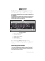
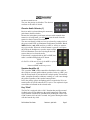
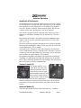
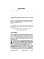
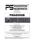
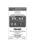
9800 Martel Road
Lenoir City, TN 37772
, 0503
Pilot’s Guide
and
Operation Manual
FAA Approved TSO C50c
JAA-Approved JTSO C50c
Revision 4
202-240-0002
April 2009
Patent No 5,903,227 and 6,160,496
Audio Selector Panel
with Intercom System
Flying Never Sounded So Good!®
PS Engineering, Inc. 2009 ©
Copyright Notice
Copyrighted information in this manual is subject to change without notice. PS Engineering
reserves the right to improve or change the products or contents of this manual, without
notification of any person or agency. The contents of this pilot’s guide may be downloaded,
stored and reprinted for personal use provided that this copyright information is included.
Commercial use is strictly prohibited. For further information contact the Publications Manager at PS Engineering, Inc., 9800 Martel Road, Lenoir City, TN 37772. Phone (865) 9889800
PAC24-Series Pilot Guide
Revision 4, April 2009
Page 1
This Pilot Guide provides detailed operating instructions for
the PS Engineering PAC24-series, High Performance Audio
Selector Panel/Intercom Systems. Please read it carefully before using the equipment so that you can take full advantage of
its capabilities.
This document is divided into three sections covering the basic
operating areas of the PAC24 systems. They are transceiver
selection, audio selector, and intercom.
1
4
5
2
3
PAC24 Controls
1)
2)
3)
4)
5)
Receiver Source Selection
Transmitter Selection
Volume / Power Controls
Speaker Selector
Intercom Mode Selector
Power Switch (3) (EMG-Fail Safe Operation)
Unit power is turned on and off by pushing the center (pilot) volume
knob. The power switch controls the audio selector panel functions
and intercom.
Single Panel Fail Safe Operation
In the OFF or "EMG" position, the pilot is connected directly to Com
1. This allows communication capability regardless of unit condition. Any time power is removed or turned OFF, the audio selector
will be placed in the fail-safe mode.
Page 2
PAC24-Series Pilot Guide
Dual Panel Fail Safe Operation
In a dual installation, the PAC24 designated as Pilot’s at installation,
will default to Com 1. The audio panel designated as copilot will not
operate in the off position. This prevents compromising the pilot’s audio capability in the event of a dual audio panel problem.
Microphone Selector (2)
There are 10 pushbuttons associated with the communications transceivers. The lower buttons control which transceiver is selected for
transmit.
Receive
Transmit
The PAC24 gives priority to the pilot’s PTT. If the copilot it transmitting, and the pilot presses his PTT, the pilot’s microphone will be heard over the selected transmitter.
The PAC24 has an automatic selector mode. Audio from
the transceiver selected by the Xmit button is automatically heard in the headsets and speaker (if selected). You
can check this function by switching from COM 1 to
COM 2 and watch the selected audio light on the selector
change from COM 1 to COM 2. This ensures the pilot
will always hear the audio from the transceiver he is
transmitting on.
When switching from COM 1 to COM 2, while COM 2
audio had been selected, Com 1 audio will continue to be
heard. This eliminates the pilot having to switch Com 1
audio back on, if desired.
When switching from COM 1 to COM 2 while Com 2 has
NOT been selected, Com 1 audio will be switched off. In
essence, switching the mic selector will not effect the selection of Com
receiver audio. This is true of all transmitter selections.
When the duplex, or TELEPHONE mode is implemented, Com 5 becomes the “TEL” position. In a single installation, the intercom mode
PAC24-Series Pilot Guide
Revision 4, April 2009
Page 3
select switch determines who is on the phone:
ISO - pilot,
CREW - pilot and copilot,
ALL - pilot, copilot, passengers
In a standard dual installation, the pilot and copilot can select TEL
mode independently by pressing their respective COM 5 button. The
passengers are on the phone only when the pilot has selected TEL mode
and his switch is in the ALL position. The copilot cannot put the passengers on the phone, and the passengers can only get on the phone
when the pilot is on the phone.
In an observer dual installation, the crew box works like a single installation. The observer is treated like a passenger, so he would be on the
phone line when COM5X is selected and the intercom switch is in ALL
mode. The observer cannot select telephone mode independently.
Stuck Microphone Protection
The PAC24 has a function designed to prevent unintentional radio
transmissions and blocked frequencies. After 35 seconds of continuous
PTT on any input, the PTT line is lifted, and will remain unkeyed until
the PTT input is recycled.
NOTE: Selecting the COM 5 –TEL– mode will disable pilot and copilot
intercom, as the intercom circuit is transferred to the telephone use. In
crew or ISO mode, selecting TEL mode removes the passengers access
to the telephone.
Swap Mode (Remote transfer of com transceivers)
With a yoke mounted, normally open, momentary switch, the pilot can
change from the current Com transceiver another by depressing this
switch. Activating the swap switch will select the next transceiver, cycling from 1 to 2 to 3 etc.
Observer transmit selection (part number –040X).
If the installation uses a dual panel, observer configuration, the crew
panel serves the pilot and copilot, while the second audio panel serves
the observer.
The pilot and copilot have access to all transceivers. The observer can
access any radio that the crew does not have selected for transmit. If the
crew selects a radio for transmit that the observer has previously selected, all parties can transmit, but the pilot, copilot, have priority over
the observer (in that order). If the observer selects a different radio, and
then attempts to re-select a radio in use by the crew, the observer will
Page 4
PAC24-Series Pilot Guide
not have transmit access.
The crew has priority on all radios. The observer
can listen to all radios if desired.
Receive Audio Selector (1)
Receiver audio is selected through 9 momentary
push-button, backlit switches.
Because the microphone push-button selector switch controls what
transceiver is being heard, you will always hear the audio from the
transceiver that is selected for transmit.
The users can identify which receivers are selected by noting which of
the green switch LEDs are illuminated. Push buttons for Nav 1, Nav 2,
MKR (Marker), and AUX (auxiliary or ADF in –0500), are momentary type switches. When one of these buttons is pressed, it will place
the audio in the headphone or speaker output, and the
LED will illuminate. Press the switch again and will
remove that receiver from the audio.
If the aircraft is equipped with an ADF or DME, that
audio is available through the AUX button.
NOTE:
On PAC24 –0500 units (Vertical) the AUX is replaced
with ADF
button and DME audio not present.
Speaker Amplifier (4)
The 3-position "SPR" switch controls the distribution of the audio in
the cockpit or external (public address) speakers. In the up “SPR” position all selected audio is presented to the cockpit speaker. Unswitched
audio, (autopilot disconnect, altimeter warning, etc.) will come through
the speaker regardless of the speaker button position.
In PA, the primary (pilot) microphone audio is routed to the PA or external speaker (J3 pin B) when the PTT is active. The copilot mic input
can continue to transmit on the selected radio.
Key “Click”
The PAC24 is equipped with a “click” function that provides an aural
feedback to the user in addition to the tactile button push. This sound
can be enabled or disabled by simultaneously holding the COM 1 and
COM 2 buttons in for at least 5 seconds. Any person hearing the radios
will also hear the key click.
PAC24-Series Pilot Guide
Revision 4, April 2009
Page 5
Allow at least 20 seconds between turning the key click on and off.
Split Mode
The PAC24 has a flexible split mode, which allows one pilot to use one
transceiver while the other can communicate on another. There are differences in the Split Mode in a single, or a dual audio panel installation.
Note:
Due to the nature of VHF communications signals, and
the size constraints in general aviation aircraft, it is
probable that there will be some bleed-over in the Split
mode, particularly on adjacent frequencies.
PS Engineering makes no warranty about the suitability
of Split Mode in all aircraft conditions.
Split Mode, Single panel
The split mode can be activated at any time by pressing the desired
combination of XMT buttons. For instance, to activate a Com 1/Com 2
split, press and hold the Com 1 button, and then press the Com 2 button
while holding the Com 1 button. This places the pilot on Com 1 and the
Copilot on Com 2.
Split mode for Com 5, in normal (not TEL/Duplex) is possible.
Pilot on Com 2, with copilot on Com 3, Com 4 or Com 5, is also possible.
Note: Split Mode does not turn off other (Nav, ADF, etc.) selected audio to pilot.
Copilot does not hear other selected radios. Passengers will hear the pilot’s audio selection
Split Mode, Dual Panel
In a dual panel installation, both pilots have access to any combination
of transceivers. Because there is cross communication, each PAC24
knows the other unit’s transmitter selection. The audio panel designated
as “Pilot’s” will have transmission priority over the panel designated as
copilot’s, when both panels are keyed for transmit on the same radio.
It is not necessary to activate the split mode by holding the buttons in a
dual installation.
Page 6
PAC24-Series Pilot Guide
Intercom Operation
IntelliVox® VOX-Squelch
No adjustment of the IntelliVox® squelch control is necessary. There is
no field adjustment. Through individual signal processors, the ambient
noise appearing in all six microphones is constantly being sampled.
Non-voice signals are blocked. When someone speaks, only their microphone circuit opens, placing their voice on the intercom.
The system is designed to block continuous tones, therefore people
humming or whistling in monotone may be blocked after a few moments.
For consistent performance, any headset microphone must be placed
within ¼-inch of your lips, preferably against them. (ref: RTCA/DO214, 1.3.1.1 (a)).
It is also a good idea to keep the microphone out of a direct wind path.
Moving your head through a vent air stream may cause the IntelliVox®
to open momentarily. This is normal.
The IntelliVox® is designed to work with normal aircraft cabin noise
levels (70 dB and above). It loves airplane noise! Therefore, it may not
recognize speech and clip syllables in a quiet cabin, such as in the hangar, or without the engine running. This is normal.
For optimum microphone performance, PS Engineering recommends
installation of a Microphone Muff Kit from Oregon Aero (1-800-8886910). This will not only optimize VOX performance, but will improve
the overall clarity of all your communications.
Volume Control (3)
The volume control is a concentric knob. The inner knob
adjusts the loudness of the intercom for the pilot (in single
panel installation) and the outer
knob controls copilot and passenger volume. It has no effect
on selected radio levels or music input levels.
In dual installation, the inner knob controls the main volume (the person connected to the audio panel) and the outer knob controls the passengers.
Intercom Modes (5)
The lower switch on the left side of the audio panel is a 3-position
PAC24-Series Pilot Guide
Revision 4, April 2009
Page 7
mode switch that allows the crew to tailor the intercom function to best
meet the current cockpit situation.
Single Installation Intercom Modes
ISO: The pilot is isolated from the intercom and is connected only to the
aircraft radio system. He will hear the selected aircraft radio reception
(and sidetone during radio transmissions). The copilot will hear passengers’ intercom and entertainment, while passengers will hear copilot,
intercom and entertainment.
ALL: All parties will hear the aircraft radio and intercom. All will hear
entertainment. During any radio or intercom communications, the music volume automatically decreases. The music volume increases gradually back to the original level after communications have been
completed.
CREW: Pilot copilot and passengers are
connected on one intercom channel and
have access to the selected aircraft radios. They may also listen to Entertainment. In a single panel installation without expansion, the passengers
will also hear what the copilot hears
Dual Installation Intercom Modes
ISO: The primary pilot connected to the PAC24 is isolated from the intercom and is connected only to the aircraft radio system. He will hear
the selected aircraft radio reception (and sidetone during radio transmissions). The crewmember on the other audio panel will hear locally selected radio audio, passengers’ intercom and entertainment, while passengers will hear the radio, intercom and entertainment.
ALL: All parties will hear the aircraft radio and intercom. All will hear
entertainment. During any radio or intercom communications, the music volume automatically decreases. The music volume increases gradually back to the original level after communications have been completed.
CREW: Pilot and copilot are connected on one intercom channel and
have exclusive access to the locally selected aircraft radios. They may
also listen to Entertainment. Passengers can continue to communicate
with themselves without interrupting the Crew and also may listen to
Entertainment.
Page 8
PAC24-Series Pilot Guide
Entertainment Input
The audio selector panel has provisions for one entertainment input device in each audio panel. The volume control does not affect music
level.
Anytime a person speaks on the intercom, or there is radio traffic, the
music will be muted. It will return gradually, through the use of SoftMute™ circuitry.
The SoftMute™ can be defeated for a “Karaoke Mode” (music does not
mute) by pressing the NAV1 and NAV2 buttons simultaneously for at
least 3 seconds. Pressing the buttons again will reactivate SoftMute™.
While in the ISO (Isolate) mode, the non-isolated crewmember and passengers will hear entertainment. When in the ALL mode, all persons
will hear the entertainment source.
Music Off
“Music Off mode” may be selected in cases where a music input is not
connected, or in use, but audio noise can be heard due to other loads or
cross-talk in the system.
Music can be inhibited completely by pressing NAV1 and AUX
(ADF in –0500) for at least 3 seconds.
Music Off will override karaoke mode
Telephone Mode
The Com 5 mode can serve as a full duplex interface for telephone systems if the installation is correctly configured. When interfaced with an
approved airborne telecommunications system, the PAC24 can serve as
an audio control and distribution center. The crewmember’s telephone
access is the "Com 5" button on the audio panel. When Com 5 is active
in the duplex mode, the TX button will blink about twice as fast as the
normal transmit rate.
When the intercom is in ALL mode, the pilot can speak on the phone
only if the Com 5 is selected for transmit (Com 5 XMT button activated). All intercom positions will hear the telephone conversation. All
will hear selected audio. Com 1 audio is automatically heard in the
headsets. The pilot and copilot will have transmit capability on the
other selected transceiver, simply by using their respective PTT switch.
In CREW mode, the pilot and copilot are may use the telephone, with
their respective hook switch (the pilot selects Com 5 on the Xmt selector). Any passenger who places their switch into the off-hook position
PAC24-Series Pilot Guide
Revision 4, April 2009
Page 9
will also have access to the phone, and all four passengers will hear
the conversation.
In ISO intercom mode, when the PAC24 is in the Com 5 mode, the
pilot position is in the "Phone Booth." Only the pilot will hear the
telephone, and only he will be heard. He will also have access to
Com 1 or 2, and will transmit on that radio using the PTT. All selected audio is provided.
Note: Because the cell phone uses an intercom circuit, all stations on that circuit will lose intercom capability when the cell
phone is in use.
Internal Recorder System (Optional)
The Intercom Recording System (referred to here as the IRS) is a
digital recording system allowing automatic storage and playback of
aircraft radio traffic.
Operating as a continuous loop recorder, (first message received will
be the last heard), the recorder has one minute of recording time or
up to 16 messages. With its own built in VOX circuit, there are no
buttons to press to start recording. The system automatically begins
to record the instant the radio becomes active. Only aircraft radio
audio in pilot’s headset is recorded and only the pilot will hear the
playback audio.
Recorder Operation
Recording is automatic; there is no action required by the pilot. To
play back the last recorded message, simply press the momentary
switch associated with the IRS. Each additional press of the button
will play the preceding recorded message. You must wait for the
message to finish playing before accessing the prior message.
To cancel the playback, press and hold the playback button for two
seconds. The next time the button is pressed, the next earlier message will be heard.
Concurrent Messages
When a recorded message is playing there is no recording of incoming messages. Both the playback and the received radio traffic will
be presented to the pilot headset..
Page 10
PAC24-Series Pilot Guide
Warranty and Service
Warranty
In order for the factory warranty to be valid, the installations in a certified
aircraft must be accomplished by an FAA-certified avionics shop and authorized PS Engineering dealer. If the unit is being installed by a noncertified individual in an experimental aircraft, a factory-made harness
must be used for the warranty to be valid.
PS Engineering, Inc. warrants this product to be free from defect in material and workmanship for a period of three (3) years from the date of sale.
In the event of a problem, contact the authorized PS Engineering Dealer
where the product was purchased for assistance. Units will not be accepted
by PS Engineering for repair without a Return Authorization.
During the first twelve (12) months of the warranty period, PS Engineering,
Inc., at its option, will send a replacement unit at our expense if the unit
should be determined to be defective after consultation with the PS Engineering dealer who sold the unit and a PS Engineering, Inc. factory technician.
For the remaining twenty-four (24) months of the PAC24-series, three-year
warranty period, PS Engineering, Inc., at its option, will send a replacement
unit at the customers expense if the unit should be determined to be defective after consultation with an authorized PS Engineering dealer.
All transportation charges for returning the defective units are the responsibility of the purchaser. All domestic transportation charges for returning the
exchange or repaired unit to the purchaser will be borne by PS Engineering,
Inc. The risk of loss or damage to the product is borne by the party making
the shipment, unless the purchaser requests a specific method of shipment.
In this case, the purchaser assumes the risk of loss.
This warranty is not transferable. Any implied warranties expire at the expiration date of this warranty. PS Engineering SHALL NOT BE LIABLE
FOR INCIDENTAL OR CONSEQUENTIAL DAMAGES. This warranty
does not cover a defect that has resulted from improper handling, storage or
preservation, or unreasonable use or maintenance as determined by us. This
warranty is void if there is any attempt to dissemble this product without
factory authorization. This warranty gives you specific legal rights, and you
may also have other rights, which may vary from state to state. Some states
do not allow the exclusion of limitation of incidental or consequential damages, so the above limitation or exclusions may not apply to you.
All items repaired or replaced under this warranty are warranted for the
remainder of the original warranty period. PS Engineering, Inc. reserves
PAC24-Series Pilot Guide
Revision 4, April 2009
Page 11
the rights to make modifications or improvements to the product without obligation to perform like modifications or improvements to previously manufactured products.
Factory Service
The unit is covered by a three-year limited warranty. See warranty information.
Call PS Engineering, Inc. at (865) 988-9800 before you return the unit. This
will allow the service technician to provide any other suggestions for identifying the problem and recommend possible solutions.
After discussing the problem with the technician and you obtain a Return Authorization Number, ship product to:
PS Engineering, Inc.
Attn: Service Department
9800 Martel Rd
Lenoir City, TN 37772
(865) 988-9800 FAX (865) 988-6619
Email: [email protected]
Note:
♦PS Engineering will refuse any shipment which does not have either an RMA
number, or a detailed description of the problem and a contact phone number.
♦PS Engineering will not be responsible for any units returned in US Mail
This Pilot Guide Applies to these PAC24 Models:
Model
Description
Part Number
PAC24
PAC24 Audio Control Panel with intercom
050-240-0100
PAC24 Option 1
PAC24 Audio Control Panel with intercom and
digital recorder,
PAC24 Audio Control Panel for Observer installation
PAC24 Audio Control Panel for Observer with
recorder
PAC24 Audio Control Panel with intercom,
Vertical Orientation
050-240-0200
PAC24 Special Mission Units
050-240-0503
PAC24 Observer
PAC24 Observer
Option 1
PAC24 Vertical
PAC24
Page 12
050-240-0400
050-240-0401
050-240-0500
PAC24-Series Pilot Guide