1
OPERATORS MANUAL
638 and 63C FOUR
71 8 and 71 C FOUR
828 FOUR
1088 and 108C SIX
MARINE DIESEL ENGINES
PUBLICATION NO. 038922
EDITION FIVE
OCTOBER 2006
WESTERBEKE CORPORATION' 150 JOHN HANCOCK ROAD
MYLES STANDISH INDUSTRIAL PARK' TAUNTON MA 02780
WEBSITE: WWW.WESTERBEKECOM
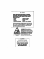
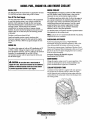
A WARNING
Exhaust gasses contain carbon Monoxide, an odorless and
colorless gas. Carbon Monoxide is poisonous and can cause
unconsciousness and death. Symptoms of Carbon Monoxide
exposure can include:
-Dizziness
- Throbbing in Temples
-Nausea
- Muscular Twitching
-Headache
- Vomiting
- Weakness and Sleepiness -Inability to Think Coherently
IF YOU OR ANYONE ELSE EXPERIENCE ANY OF THESE SYMPTOMS,
GET OUT INTO THE FRESH AIR IMMEDIATELY. If symptoms persist,
seek medical attention. Shut down the unit and do not restart
until it has been Inspected and repaired.
~---------'
'~
A WARNING DECAL is provided by
WESTERBEKE and should be nxed to a
bulkhead near your engine or generator.
\ WESTERBEKE also recommends installing
..
..\ CARBON MONOXIDE DETECTORS in the
living/sleeping quarters of your vessel.
'C-enerators Produye CARBON M9NOXIDE. The u are ine""ensive and easilu
Regular M",ntenance Required
!''''.
,
l
~~~~~
J obtainable at your local marine store.
X
CO
WA RNINGI
CALIFORNIA
PROPOSITION 65 WARNING
Marine diesel and gasoline engine
exhaust and some of its constituents
are known to the State of California
to cause cancer, birth defects,
and other reproductive harm.
SAFETY INSTRUCTIONS
INTRODUCTION
•
Read this safety manual carefully. Most accidents are
caused by failure to follow fundamental rules and precautions. Know when dangerous conditions exist and take the
necessary precautions to protect yourself, your personne4
and your machinery.
The following safety instructions are in compliance with
the American Boat and Yacht Council (ABYC) standards.
PREVENT ELECTRIC SHOCK
while engine is running. Lethal voltage is present at
these connections!
Do not operate this machinery without electrical
enclosures and covers in place.
•
Shut off electrical power before accessing electrical
equipment.
• Use insulated mats whenever working on electrical
equipment.
• Make sure your clothing and skin are dry, not damp
(particularly shoes) when handlipg electrical equipment.
• Remove wristwatch and all jewelry when working on
electrical equipment.
• Electrical shock results from handling a charged
capacitor. Discharge capacitor by shorting terminals
together.
PREVENT BURNS - HOT ENGINE
A WARNING: Do not touch hot engine parts Dr
• All fuel vapors are highly explosive. Use extreme care
when handling and storing fuels. Store fuel in a
well-ventilated area away from spark-producing
equipment and out of the reach of children.
• Do 110t fill the fuel.tank(s) while the engine is mnning.
• Shut off the fuel service valve at the engine when servicing
the fuel system. Take care in catching any fuel that might
spill. DO NOT allow any smoking, open flames, or other
sources of fire near the fuel system or engine when
servicing. Ensure proper ventilation exists when servicing
the fuel system.
• Do not alter or modify the fuel system.
• Be sure all fuel supplies have a positive shutoff valve.
• Be certain fuel line fittings are adequately tightened and
free of leaks.
• Make sure a fire extinguisher is installed nearby and is
properly maintained. Be familiar with its proper use.
Extinguishers rated ABC by the NFPA are appropriate
for all applications encountered in this environment.
A WARNING: Accidental starting can cause injury
Dr death!
Always check the engine coolant level at the coolant
recovery tame
A WARNING: Steam can cause injury or death!
•
injury or death!
ACCIDENTAL STARTING
exhaust system components. A running engine gets
very hot!
•
PREVENT BURNS - EXPLOSION
A WARNING: Explosions from fuel vapors can cause
A WARNING: Do not touch AC electrical connections
•
Do not operate with the air cleaner/silencer removed.
Backfire can cause severe injury or death.
• Do not smoke or permit flames or sparks to occur near
the fuel system. Keep the compartment and the
engine/generator clean and free of debris to minimize the
chances of fire. Wipe up all spilled fuel and engine oil.
• Be aware - Diesel fuel will bum.
In case of an engine overheat, allow the engine to cool
before touching the engine or checking the coolant.
PREVENT BURNS - FIRE
• To prevent accidental starting when servicing the
generator, remove the 8 amp fuse from the control panel.
• Disconnect the battery cables before servicing the engine!
generator. Remove the negative lead first and reconnect
it last.
• Make certain all personnel are clear of the engine before
starting.
• Make certain all covers, guards, and hatches are
re-installed before starting the engine.
A WARNING: Fire can cause injury Dr death!
• Prevent flash fires. Do not smoke or permit flames or
sparks to occur near the carburetor, fuel line, filter, fuel
pump, or other potential sources of spilled fuel or fuel
vapors. Use a suitable container to catch all fuel when
removing the fuel line, carburetor, or fuel filters.
Engines & Generators
SAFETY INSTRUCTIONS
TOXIC EXHAUST GASES
ACCIDENTAL STARTING
A WARNING: Accidental starting can cause injury
A WARNING: Carbon monoxide (CO) Is a deadly gas!
or death!
• Ensure that the exhaust system is adequate to expel gases
discharged from the engine. Check the exhaust system
regularly for leaks and make sure the exhaust
manifolds/water-injected elbow L" securely attached.
• Be sure the unit and its surroundings are well ventilated.
Run blowers when running the generator set or engine.
• Do not run the generator set or engine unless the boat is
equipped with a functioning marine carbon monoxide
detector that complies with ABYCA-24. Consult your
boat builder or dealer for installation of approved
detectors.
• For additional information refer to ABYC T-22
(educational information on Carbon Monoxide).
• Disconnect the battery cables before servicing the engine/
generator. Remove the negative lead first and reconnect
it last.
• Make certain all personnel are clear of the engine before
starting.
• Make certain all covers, guards, and hatches are
re-installed before starting the engine.
BATTERY EXPLOSION
A WARNING: Battery explosion can cause injury
or death!
•
Do not smoke or allow an open flame near the battery
being serviced. Lead acid batteries emit hydrogen, a
highly explosive gas, which can be ignited by electrical
arcing or by lit tobacco products. Shut off all electrical
equipment in the vicinity to prevent electrical arcing
during servicing.
• Never connect the negative (-) battery cable to the
positive (+) connection terminal of the starter solenoid.
Do not test the battery condition by shorting the terminals
together. Sparks could ignite battery gases or fuel vapors.
Ventilate any compartment containing batteries to prevent
accumulation of explosive gases. To avoid sparks, do not
disturb the battery charger connections while the battery
is being charged.
• Avoid contacting the terminals with tools, etc., to prevent
bums or sparks that could cause an explosion. Remove
wristwatch, rings, and any other jewelry before handling
the battery.
• Always tum the battery charger off before disconnecting
the battery connections. Remove the negative lead first
and reconnect it last when disconnecting the battery.
A WARNING: Carbon monoxide (CO) is an invisible
odorless gas. Inhalation produces flu-like symptoms,
nausea or death!
• Do not use copper tubing in diesel exhaust systems. Diesel
fumes can rapidly destroy copper tubing in exhaust
systems. Exhaust sulfur causes rapid deterioration of
copper tubing resulting in exhaust/water leakage.
• Do not install exhaust outlet where exhaust can be drawn
through portholes, vents, or air conditioners. If the engine
exhaust discharge outlet is near the waterline, water could
enter the exhaust discharge outlet and close or restrict the
flow of exhaust. Avoid overloading the craft.
• Although diesel engine exhaust gases are not as toxic as
exhaust fumes from "gasoline engines, carbon monoxide
gas is present in diesel exhaust fumes. Some of the
symptoms or signs of carbon monoxide inhalation or
poisoning are:
Vomiting
Inability to think coherently
Dizziness
Throbbing in temples
Muscular twitching
Headache
Weakness and sleepiness
Nausea
BATTERY ACID
A WARNING: Sulfuric acid in batteries can cause
AVOID MOVING PARTS
severe injury or death!
A WARNING: Rotating parts can cause injury
• When servicing the battery or checking the electrolyte
level, wear rubber gloves, a rubber apron, and eye
protection. Batteries contain sulfuric acid which is
destructive. If it comes in contact with your skin, wash it
off at once with water. Acid may splash on the skin or
into the eyes inadvertently when removing electrolyte
caps.
or death!
•
Do not service the engine while it is running. If a
situation arises in which it is absolutely necessary to
make operating adjustments, use extreme care to avoid
touching moving parts and hot exhaust system
components.
Engines & Generators
--
II
SAFETY INSTRUCTIONS
ABye, NFPA AND USCG PUBLICATIONS FOR
INSTALLING DIESEL ENGINES
•
Do not wear loose clothing or jewelry when servicing
equipment; tie back long hair and avoid wearing loose
jackets, shirts, sleeves, rings, necklaces or bracelets that
could be caught in moving parts.
• Make sure all attaching hardware is properly tightened.
Keep protective shields and guards in their respective
places at all times.
• Do not check fluid levels or the drive belts tension while
the engine is operating.
• Stay clear of the drive shaft and the transmission coupling
when the engine is running; hair and clothing can easily
be caught in these rotating parts.
Read the following ABYC, NFPA and USCG publications
for safety codes and standards. Follow their
recommendations when installing your engine.
ABYC (American Boat and Yacht Council)
"Safety Standards for Small Craft"
Order from:
ABYC
3069 Solomon's Island Rd.
Edgewater, MD 21037
NFPA (National Fire Protection Association)
"Fire Protection Standard for Motor Craft"
Order from:
NFPA
11 Tracy Drive
Avon Industrial Park
Avon, MA 02322
USCG (United States Coast Guard)
"USCG 33CFR183"
Order from:
U.S. Goverument Printing Office
Washington, D.C. 20404
HAZARDOUS NOISE
A WARNING: High noise levels can cause hearing
loss/
•
•
•
Never operate an engine without its muffler installed.
Do not run an engine with the air intake (silencer)
removed.
Do not run engines for long periods with their enclosures
open.
A WARNING: Do not work on machinery when you are
mentally or physically incapacitated by fatigue!
OPERATORS MANUAL
Many of the preceding safety tips and wamings are repeated
in your Operators Manual along with other cautions and
notes to highlight critical information. Read your manual
carefully, maintain your equipment, and foHow all safety
procedures.
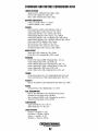
GASOLINE ENGINE AND GENERATOR INSTALLATIONS
Preparations to install an engine should begin with a
thorough examination of the American Boat and Yacht
Council's (ABYC) standards. These standards are a
combination of sources including the USCG and the NFPA.
Sections of the ABYC standards of particular interest are:
H-2 Ventilation
P-l Exhaust Systems
PA Inboard Engines
E-9 DC Electrical Systems
All installations must comply with the Federal Code of
Regulations (FCR).
Engines & Generators
iii
INSTALLATION
When installing WESTERBEKE engines and generators it is important that strict
attention be paid to the following infom1ation:
CODES AND REGULATIONS
Strict federal regulations, ABYC guidelines, and safety codes must be complied with
when installing engines and generators in a marine environment.
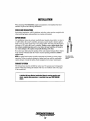
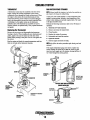
SIPHON-BREAK
For installations where the exhaust manifold/water injected exhaust elbow is close to
or will be below the vessel's waterline, provisions must be made to install a siphonbreak in the raw water supply hose to the exhaust elbow. This hose must be looped a
minimum of 20" above the vessel's waterline. Failure to use a siphon-break when
the exhaust manifold injection port is at or below the load waterline will result in
raw water damage to the engine and possible flooding of the boat.
If you have any doubt about the position of the water-injected exhaust elbow relative
to the vessel's waterline under the vessel's various operating conditions, install a
siphon-break.
NOTE: A siphon-break requires periodic inspection and cleaning to ensure proper
operation. Failure to properly maintain a siphon-break can result in catastrophic
engine damage. Consult the siphon-break manufacturer for proper maintenance.
EXHAUST SYSTEM
The exhaust hose must be certified for marine use. The system must be desigued to
prevent water from entering the exhaust under any sea conditions and at any angle
of the vessels hull.
A detailed 40 page Marine Installation Manual covering gasoline and
diesel, engines and generators, is available from your WESTERBEKE
dealer.
Engines & Generators
iv
AVAILABLE FROM
YOUR WESTERBEKE
DEALER
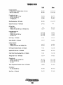
TABLE OF CONTENTS
Remote Oil Filter (Optional) ..............................21
Water Heat Connections ................................... 22
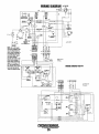
Wiring Diagram .................................................26
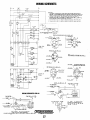
Wiring Schematic ..............................................27
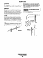
Glow Plugs .........................................................28
Starter Motor .....................................................29
Dual Output Alternators ....................................31
Alternator TestingJTroubleshooting .................. 34
Engine Troubleshooting .....................................37
Service Schedule .............................................. .41
Parts Identification .............................................2
Introduction .........................................................3
Warranty Procedures ........................................ .3
Serial Number Location .................................. .4
Admiral Control Panel .........................................5
Captain Control Panel .........................................6
Fuel, Engine Oil, and Coolant. ............................7
Preparations for Initial Start-Up .........................8
The Daily Operation .............................................9
Engine Break-In Procedure ............................... 10
Warning Lights, Alarms and Circuit Breaker .... 11
Maintenance Schedule .................................... .12
Fuel System ....................................................... 14
Cylinder Head Torque .................................... 42
Engine Adjustments ..........................................43
Oil Pressure .................................................... 44
Tachometer .....................................................43A
Engine Specifications .......................................45
FueliWater Separator ...................................... 14
Fuel Filters ...................................................... 14
Cooling System .................................................. 15
Changing Coolant ........................................... 15
Thermostat ...................................................... 16
Raw Water Intake Strainer.............................. 16
Raw Water Pump ............................................ 17
Heat Exchanger .............................................. 18
Zinc Anode ..................................................... 18
Engine Lubricating Oil ....................................... 19
Changing the Oil Filter................................... 19
Changing the Oil ............................................ 19
ZF Marine Transmission ....................................49
Borg Warner Transmission ............................... .49
Lay-Up and Recommissioning ...........................58
Torque Data .......................................................60
Metric Chart ......................................................6]
Suggested Spare Parts ......................................63
Engines & Generators
1
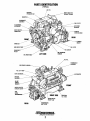
PARTS IDENTIFICATION
(TYPICAL)
FILL
COOlANT
PRESSURE CAP
WATER INJECTED
EXHAUST ELBOW
ASSEMBLY
FILTER
DC CHARGING
ALTERNATOR
AIR INTAKE
SILENCER
WMERHtAltK·-------~
CONNECTION
REAR
FLEXIBLE
MOUNT
DRIVE BELT
RAWWATERP~
FILTER
COOLER
CRANKSHAFT
PULLEY
OIL DRAIN HOSE
Oil PRESSURE
SENDOR
LEFT SIDE
Fill
THERMOSTAT
_",~"o;;l"'DLY
FUEL LIFT PUMP
ALTERNATOR
PREHEAT
SOLENOID - - - ZOAMP
CIRCUIT
BREAKER
FRONT
HBW
HURTH
TRANSMISSION
MANIFOLD
1.0. PLATE
ENGINE BLOCK
DRAIN PLUG
REAR
SHIFT LEVER
Engines & Generators
2
INTRODUCTION
This WESTERBEKE Diesel Engine is a product of
WESTERBEKE's long years of experience and advanced
technology. We take great pride in the superior durability and
dependable performance of our engines and generators.
Thank you for selecting WESTERBEKE.
In order to get the full use and benefit from your engine, it is
important that you operate and maintain it correctly. This
manual is designed to help you do this. Please read this manual carefully and observe an the safety precautions throughout. Should your engine require servicing, contact your
nearest WESTERBEKE dealer for assistance.
This is your operators manual. A parts catalog is also
provided and a technical manual is available from your
WESTERBEKE dealer. If you are planning to install this
equipment, contact your WESTERBEKE dealer for
WESTERBEKE'S installation manual.
PRODUCT SOFTWARE
Product software, (technical data, parts lists, manuals,
brochures and catalogs), provided from sources other than
WESTERBEKE are not within WESTERBEKE's control.
WESTERBEKE CANNOT BE RESPONSIBLE FOR THE
CONTENT OF SUCH SOFTWARE, MAKES NO WARRANTIES OR REPRESENTATIONS WITH RESPECT
THERETO, INCLUDING ACCURACY, TIMELINESS OR
COMPLETENESS THEREOF AND WILL IN NO EVENT
BE UABLE FOR ANY TYPE OF DAMAGE OR INJURY
INCURRED IN CONNECTION WITH OR ARISING OUT
OF THE FURNISHING OR USE OF SUCH SOF1WARE.
WESTERBEKE customers should keep in mind the time
span between printings ofWESTERBEKE product software
and the unavoidable existence of earlier WESTERBEKE
product software. The product software provided with
WESTERBEKE products, whether from WESTERBEKE or
other suppliers, must not and cannot be relied upon exclusively as the definitive authority on the respective product. It
not only makes good sense but is imperative that appropriate
representatives of WESTERBEKE or the supplier in question
be consulted to determine the accuracy and currentness of the
product software being consulted by the customer.
WARRANTY PROCEDURES
Your WESTERBEKE Warranty is included in a separate
folder. If, after 60 days of submitting the Warranty Registry
form you have not received a customer identification card
registering your warranty, please contact the factory in
writing with model information, including the engine's
serial number and commission date.
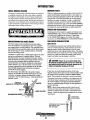
NOTES, CAUTIONS AND. WARNINGS
Customer Identification Card
As this manual takes you through the operating procedures,
maintenance schedules, and troubleshooting of your marine
engine, critical information will be highlighted by NOTES,
CAUTIONS, and WARNINGS. An explanation follows:
,
/WO/WESTERBEKE
NOTE: An operating procedure essential to note.
Customer Identification
MR. ENGINE OWNER _ __
NUUNSTREET ___________
HOMETOWN,
Model _ _ _ __
A CAUTION: Procedures which, if nDt strictly
observed, can result in the damage Dr destruction of
your engine.
Ser.# _ _ __
A WARNING: Procedures which, if not properly followed, can result in personal injury or loss of life.
Engines & Generators
3
INTRODUCTION
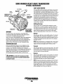
SERIAL NUMBER LOCATION
ORDERING PARTS
The engine's model number and serial number are located on
a nameplate mounted on the side of the engine's manifold.
The engine's serial number can also be found stamped into
the engine block on the flat sutface of the block just above
and inboard of the injection pump. Take the time to enter this
information on the illustration of the nameplate shown below,
as this will provide a quick reference when seeking technical
information andlor ordering repair parts.
Whenever replacement parts are needed, always provide the
engine model number and serial number as they appear on
the silver and black nameplate located on the manifold. You
must provide us with this infonnation so we may properly
identify your engine. In addition, include a complete part
description and part number for each part needed (see the
separately furnished Parts List). Insist upon WES1ERBEKE
packaged parts because will fit or generic parts are frequently
not made to the same specifications as original equipment.
SPARES AND ACCESSORIES
Certain spares will be needed to support and maintain your
WES1ERBEKE engine. Your local WES1ERBEKE dealer
will assist you in preparing an inventory of spare parts.
See the SPARE PARTS page in this manual. For engine
accessories, see WESTERBEKE'S ACCESSORIES brochure.
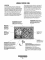
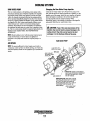
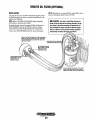
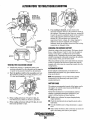
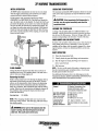
UNDERSTANDING THE DIESEL ENGINE
RAW WATER COOLING SYSTEM
The diesel engine closely resembles the gasoline engine,
since the mechanism is essentially the same. The cylinders
are arranged above a closed crankcase. The crankshaft is the
same general type as a gasoline engine, and the diesel engine
has the same type of valves, camshaft, pistons, connecting
rods and lubricating system.
Therefore, to a great extent, a diesel engine requires the same
preventive maintenance as a gasoline engine. The most
important factors are proper ventilation and proper mainte·
nance of the fuel, lubricating and cooling systems. Fuel and
lubricating filter elements must be replaced at the time
periods specified, and frequent checking for contaminant's
(water, sediment, etc.) in the fuel system is also essential.
Another important factor is the consistent use of the same
brand of high detergent diesel lubrication oil designed
specifically for diesel engines.
The diesel engine does differ from the gasoline engine,
however, in its method of handling and firing of fuel. The
carburetor and ignition systems are replaced by a single
component - the fuel injection pump - which performs the
function of both.
Siphon-Break
GLOW PLUG,
ENERGIZED BY THE PREHEAT
For installations where the water injected exhaust elbow is
close to or will be below the vessels waterline, provisions
must be made to install a siphon·break in the raw water
supply hose to the water injected exhaust elbow. The siphon·
break provides an air vent in the raw water cooling system to
prevent raw water from filling the exhaust system and the
engine's cylinders when the engine is shutdown.
A
CAUTION: Failure to use a siphon-break when
the exhaust manifold injection port is at or below the
load waterline will result in raw water damage to the
engine and possible flooding of the boat.
If you have any doubt about the position of the water·
1TT£'Al""""""",",
l--~- DIESEL FUEL SPRAY
injected exhaust elbow relative to the vessels waterline under
the vessels various operating conditions, install a siphonbreak. This precaution is necessary to protect your engine.
The siphon·break must be installed in the highest point of a
hose that is looped a minimum of 20 inches (51cm) above
the vessels waterline. This siphon·break must always be
above the waterline during all angles of vessel operation to
prevent siphoning.
NOTE: A siphon·break requires periodic inspection and
cleaning to ensure proper operation. Failure to properly
maintain a siphon-break can result in catastrophic engine
damage. Consult the siphon-break manufacturer for proper
maintenance.
SIPHON-BREAK WITH STAINLESS
LOOP FOR 314" HOSE
PART NO.045368
Engines & Generators
4
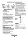
ADMIRAL CONTROL PANEL
DESCRIPTION
When the engine is shut down with the key switch turned off,
the water temperature gauge will continue to register the last
temperature reading indicated by the gauge before electrical
power was turned off. The oil pressure gauge will fall to zero
when the key switch is turned off. The temperature gauge
will once again register the engine's true temperature when
electrical power is restored to the gauge.
A separate alarm buzzer with harness is supplied with every
Admiral Panel. The installer is responsible for electrically connecting the buzzer to the four-pin connection on the engine's
electrical harness. The installer is also responsible for installing
the buzzer in a location where it will be dry and where it will
be audible to the operator should it sound while the engine is
running. The buzzer will sound when the ignition key is turned
on and should silence when the engine has started and the
engine's oil pressure rises above 15 psi (1.1 kglcm2).
This manually-operated control panel is equipped with a
KEY switch and RPM gauge with an ELAPSED TIME
meter which measures the engine's running time in hours and
in 1110 hours. The panel also includes a WA1ER 1EMPERATURE gauge which indicates water temperature in degrees
Fahrenheit, an OIL PRESSURE gauge which measures the
engine's oil pressure in pounds per square inch, and a DC
control circuit VOLTAGE gauge which measures the system's voltage. All gauges are illuminated when the key
switch is turned on and remain illuminated while the engine
is in operation. The panel also contains two rubber-booted
pushbuttons, one for PREHEAT and one for START.
Oil PRESSURE GAUGE: THIS GAUGE IS GRADUATED IN POUNDS PER SQUARE INCH (PSI) AND IS
ILLUMINATED WHILE THE KEY SWITCH IS TURNED
ON. THE ENGINE'S NORMAL OPERATING OIL
PRESSURE RANGES BElWEEN 30 - 60 psi
(2.1 - 4.2 kg/em').
WATER TEMPERATURE GAUGE: THIS GAUGE IS
GRADUATED IN DEGREES FAHRENHEIT AND IS
IlWMINATED WHILE THE KEY SWITCH IS
TURNED ON. THE ENGINE'S NORMAL OPERATING
TEMPERATURE IS 170' -190· F(77" - aa·c).
RPM GAUGE: REGIS·
TERS REVOLUTIONS
PER MINUTE OF THE
ENGINE AND CAN BE
RECALIBRATEO FOR
ACCURACY FROM THE
REAR OF THE PANEL.
HOURMETER:
REGISTERS ELAPSED
TIME, AND SHOULD BE
USED AS A GUIDE FOR
THE MAINTENANCE
SCHEDULE.
_ _-"'" SWITCH: PROVIDES
POWER ONLY TO THE
INSTRUMENT PANEL
CLUSTER
DC VOLTMETER:
INDICATES THE AMOUNT THE
BATTERY IS BEING CHARGED.
SHOULb SHOW 13VTO 14V.
PREHEAT
PRESSED, ENERGIZES THE
ALTERNATOR'S EXCITER, THE FUEL LIFT PUMP, THE
FUEL SOLENOID ON THE INJECTION PUMP, AND THE
ENGINE'S GLOW PLUGS. IT BYPASSES THE ENGINE'S
OIL PRESSURE ALARM SWITCH. IN ADDITION, THIS
BUTTON ENERGIZES THE START BUTTON.
AUTOMATIC ALARM SYSTEM
COOLANT TEMPERATURE ALARM: AN ALARM BUZZER HAS BEEN
SUPPLIED WITH THE INSTRUMENT PANEL. IF THE ENGINE'S COOLANT
REACHES 210" F(99"C), THIS SWITCH WILL CLOSE SOUNDING THE
ALARM WHICH WILL EMIT A CONTINUOUS SIGNAL.
START BUTTON: WHEN PRESSED. ENERGIZES THE
STARTER'S SOLENOID WHICH CRANKS THE ENGINE.
THIS BUTTON WILL NOT OPERATE ELECTRICALLY
UNLESS THE PREHEAT BUTTON IS PRESSED AND HELD
AT THE SAME TIME.
Oil PRESSURE ALARM: AN OIL PRESSURE ALARM SWITCH IS
LOCATED OFF THE ENGINE'S OIL GALLERY. THIS SWITCH MONITORS
THE ENGINE'S OIL PRESSURE. SHOULD THE ENGINE'S OIL PRESSURE
FALL TO 5 -10 psi (OA - 0.7 kg/em'), THE SWITCH WILL CLOSE SOUNDING THE ALARM. IN THIS EVENT, THE ALARM WILL EMIT A PULSATING
SIGNAL
Engines & Generators
5
CAPTAIN CONTROL PANEL
DESCRIPTION
The panel also includes an alarm buzzer for low OIL
PRESSURE or high COOLANT 1EMPERATURE. The
RPM gauge is illuminated when the KEY switch is turned on
and remains illuminated while the engine is in operation.
This manually-operated control panel is equipped with a
KEY switch, an RPM gauge, PREHEAT and START buttons, an JNSTRL'MEI\TT JEST button and three indicator
lamps, one for AL1ERNATOR DISCHARGE, one for low
OIL PRESSURE, and one for high ENGINE COOLANT
1EMPERATURE.
ALARM: THE ALARM WILL SOUND IF THE ENG1NE'S OIL PRESSURE FALLS
BELOW 5 -10 psi (0.4 -0.7 kg/em'). IN THIS EVENT, THE ALARM WILL EMIT A
PULSATING SIGNAL. THE ALARM WILL ALSO SOUND IF THE COOLANT
TEMPERATURE IN THE FRESHWATER COOLING CIRCUIT RISES TO
210 a F (99°C). IN THiS EVENT, THE ALARM WILL EMIT A CONTINUOUS SIGNAL.
NOTE: THE ALARM WILL SOUND WHEN THE KEY SWITCH IS TURNED ON. THIS
SOUNDING IS NORMAL. ONCE THE ENGINE STARTS AND THE ENGINE'S OIL
PRESSURE REACHES 15 pSi (1.1 kg/em'), THE ALARM WILL SILENCE.
RPM GAUGE: REGISTERS REVOLUTIONS
PER MINUTE OF THE ENGINE AND CAN BE
RECALIBRATED FOR ACCURACY FROM
THE REAR OFTHE PANEL.
Oil PRESSURE
ALARM LIGHT
ALTERNATOR
ALARM LIGHT
TEST BUTTON: WHEN
PRESSED, TESTS THE
ALTERNATOR, THE OIL
PRESSURE, AND THE
COOLANT TEMPERATURE CONTROL CIRCUITS. WHEN PRESSED,
THE ALTERNATOR, THE
OIL PRESSURE, AND
THE WATER TEMPERATURE INDICATOR
LIGHTS ILLUMINATE IN
ADDITION TO SOUNDING THE ALARM
BUZZER,
KEY SWITCH: PROVIDES
POWER ONLY TO THE
lNSTRUMErijT PANEL
CLUSTER.
WATER TEMPERATURE
ALARMUGHT
START BUTTON: WHEN PRESSED, ENERGIZES THE
STARTER'S SOLENOID WHICH CRANKS THE ENGINE. THIS
BUTTON WILL NOT OPERATE ELECTRICALLY UNLESS THE
PREHEAT BUTTON IS PRESSED AND HELD AT THE SAME
TIME.
Engines & Generators
6
BUTTON: WHEN PRESSED, ENERGIZES THE
ALTERNATOR'S EXCITER, THE FUEL LIFT PUMP, THE FUEL
SOLENOID ON THE INJECTION PUMP, AND THE ENGINE'S
GLOW PLUGS, AND BYPASSES THE ENGINE'S OIL PRESSURE ALARM SWITCH. IN ADDITION, THIS BUTTON ENERGIZES THE START BUTTON.
DIESEL FUEL, ENGINE OIL AND ENGINE COOLANT
DIESEL FUEL
ENGINE COOLANT
Use fuel1hat meets 1he requirements or specification of Class
2-D (ASTM), and has a cetane rating of #45 or better.
WESTERBEKE recommends a mixture of 50% antifreeze
and 50% distilled water. Distilled water is free from the
chemicals that can corrode internal engin~ surfaces.
The antifreeze performs double duty. It allows the engine to
run at proper temperatures by transferring heat away from
the engine to the coolant, and lubricates and protects the
cooling circuit from rust and corrosion. Look for a good
quality antifreeze 1hat contains Supplemental Cooling
Additives (SCAs) that keep the antifreeze chemically
balanced, crucial to long term protection.
The distilled water and antifreeze should be premixed before
being poured into the cooling circuit.
Care Of The Fuel Supply
Use only clean diesel fuel! The clearance of1he components
in your fuel injection pump is very critical; invisible dirt
particles which might pass through 1he filter can damage
these finely finished parts. It is important to buy clean fuel,
and keep it clean. The best fuel can be rendered
unsatisfactory by careless handling or improper storage
facilities. To assure that the fuel going into the tank for your
engine's daily use is clean and pure, the following practice
is advisable:
Purchase a well-known brand of fuel.
Install and regularly service a good, visual-type fuel
filter/water separator between the fuel tank and the engine.
The Raycor 500 FG or 900 FG are good examples of such
filters.
NOTE: Lookfor the new environmentally-frierully long lasting
antifreeze that is now available.
PURCHASING ANTIFREEZE
Rather than preparing the mixture, WESTERBEKE
recommends buying the premixed antifreeze so that so that
when adding coolant the mixture will always be correct
There are two common types of antifreeze, Ethylene Glycol
(green) and Propylene Glycol (red/purple), either can be used
but do not mix the two and if changing from one to another,
flush the engine thoroughly.
ENGINE OIL
Use a heavy duty engine oil with an API classification of Cf
or CG-4 or better. Change the engine oil after an initial 50
hours of break-in operation, and every 100 hours of operation
1hereafter. For recommended oil ,use sAE 15W-40
(oil viscosity) and stay with 1he same brand of oil thru-out
the life of the engine.
Premixed antifreeze for DIESEL Engines:
Specification #ASTM 5345.
MAINTENANCE
Change the engine coolant every five years regardless of the
number of operating hours as the chemical additives that
protect and lubricate the engine have a limited life.
A CAUTION: Do not allow two Dr mDre brands of
engine oil to mix. Each brand contains its own additives;
additives of different brands could reacl in the mixture
to produce properties harmful tD your engine.
COOLANT RECOVERY TANK
A coolant recovery tank kit is supplied with each generator.
The purpose of this recovery tank to allow for engine
coolant expansion and contraction during engine operation,
without the loss of coolant and without introducing air into
the cooling system .
is
. ~. II
Engines & Generators
7
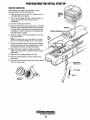
PREPARATIONS FOR INITIAL START-UP
PRESTARTINSPECTION
Before starting your engine for the first time or after a
prolonged layoff, check the following items:
o Check the engine oil level. Add oil to maintain the level
at the high mark on the dipstick.
o Turn on the fuel supply, then check the fuel supply and
examine the fuel filter/water separator bowl for
contaminants.
Check the transmission fluid level.
Check the DC electrical system. Inspect wire connections
and battery cable connections. Make certain the positive
(+) battery cable is connected to the starter solenoid and
the negative (-) cable is connected to the engine ground
stud (this location is tagged).
Check the coolant level in both the plastic recovery tank
and at the manifold.
COOlANT
'RECOVERY
TANK
o
o
o
NOTE: If the engine has not yet been filled with coolant,
refer to the COOliNG SYSTEM section of this manual.
D Visually examine the engine. Look for loose or missing
parts. disconnected wires, and unattached hoses. Check
the threaded connections and engine attachments.
D Make certain there is proper ventilation around the
engine. An ample supply is necessary for proper engine
performance.
D Make sure the mounting installation is secure.
D Ensure the propeller shaft is securely attached to the
transmission.
D Open the thru-hull and make certain raw water is primed
to the raw water strainer.
,-""-_- OIL DIPSTICK
PRESS IN TIGHT
/!~_
SIDE OIL FILL
(TYPICAL)
Engines & Generators
8
FULL (MAX)
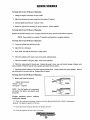
STARTING - STOPPING PROCEDURE
CHECKLIST
FAILURE TO START
Follow this check list each day before starting your engine.
D Visually inspect the engine for fuel, oil, or water leaks.
D Check the engine oil level (dipstick).
D Check the coolant level in coolant recovery tank.
Periodically check the manifold coolant leveL.
D Check the transmission fluid level.
D Check your fuel supply.
D Look for clean fuel in the fuel filter/water separator
transparent bowL
Check for loose wires at the alternator and make sure its
mounting is secure.
D Check the starting batteries (weekly)
D Check drive belts for wear and proper tension (weekly).
D Visually inspect the raw water pump for leakage.
If the engine fails to start when the start button is pressed for
5 seconds, wait for at least 30 seconds and repeat the starting
procedure. Make certain the transmission control is in th~
neutral position as some engines have a neutral safety SWItch
to prevent starting in gear.
Never run the starter for more then 30 seconds. If the engine
fails to start, refer to the TROUBLESHOOTING CHART in
this manual.
A CAUTION: Prolonged cranking intervals without
the engine starting can result in the engine exhaust
system filling with raw water. This may happen because
the pump is pumping raw water through the raw water
cooling system during cranking. This raw water can
enter the engine's cylinders by way of the exhaust
manifold once the exhaust system tills. Prevent this
from happening by clOSing the raw water supply
through-hull shutoff, draining the exhaust muffler, and
correcting the cause of the excessive engine cranking.
Engine damage resulting from raw water entry is not a
warrantable issue; the owner/operator should keep this
in mind.
STARTING THE ENGINE
1. Place the transmission in neutral, throttle advanced.
NOTE: Hydraulically operated transmissions have a
neutral safety switch through which the starter solenoid
energizing circuit passes. This switch is open when the
transmission is in gear so the starter solenoid will not
energize.
2. Tum the KEY SWITCH to the ON position (2 o'clock).
(If the panel is energized, gauges are lit) and the alarm
buzzer will pulse.
3. Press the PREHEAT BUTfON, and hold for 5 to 15
seconds depending how cold it is .. (The foellift pump is
priming the engine and the preheat is activated).
4. Continue pressing the PREHEAT BUTTON and press
the START BUTTON. (The starter motor is cranking the
engine).
5. Release the START and PREHEAT BUTTON as the
engine starts. The alarm buzzer should silence as the oil
pressure rises.
6. With the engine running, check the instruments for
proper oil pressure and battery charging voltage. Also
check for overboard discharge of exhaust water. The
water temperature will rise slowly until the thermostat
opens. Do not engage the gear shift until the temperature
is close to nonnal.
STOPPING PROCEDURE
To stop the engine, bring the throttle to an idle position and
place the transmission in neutral. Allow the engine to idle for
a few moments to stabilize temperatures, then shut the
engine down by turning off the key switch.
NOTE: When starting:
A voltage drop will occur
when the preheat button
is depressed.
NOTE: Never attempt to engage the starter while the
engine is ntnning.
It is important to closely monitor the panel gauges.
Become aware of the normal engine readings and take
immediate action if these readings start to vary.
If a "smart" regulator is part of the charging system,
allow about 50 second~ for the RPM gauge to activate.
Engines & Generators
9
ENGINE BREAK-IN PROCEDURE
DESCRIPTION
Although your engine has experienced a minimum of one
hour of test operations at the factory to make sure accurate
assembly procedures were followed and that the engine operated properly, a break-in time is required. The service life of
your engine is dependent upon how the engine is operated
and serviced during its initial 50 hours of use.
Breaking-in a new engine basically involves seating the piston rings to the cylinder walls. Excessive oil consumption
and smoky operation indicate that the cylinder walls are
scored, which is caused by overloading the engine during the
break-in period.
Your new engine requires approximately 50 hours of initial
conditioning operation to break in each moving part in order
to maximize the performance and service life of the engine.
Perfonn this conditioning carefully, keeping in mind the following:
1. Start the engine according to the STARTING PROCEDURE section. Run the engine at fast idle while checking
that all systems (raw water pump, oil pressure, battery
charging) are functioning.
2. Allow the engine to wann up (preferably by running at
fast idle) until the water temperature gauge moves into
the 130 - 140°F (55 - 60°C) range.
3. While using the vessel, run the engine at various engine
speeds for the first 25 hours. Avoid prolonged periods of
idling.
4. Avoid rapid acceleration, especially with a cold engine.
5. Use caution not to overload the engine. The presence of a
grey or black exhaust and the inability of the engine to
reach its full rated speed are signs of an overload.
.6. During the next 25 hours, the engine may be operated at
varying engine speeds, with short runs at full rated rpm.
Avoid prolonged idling during this break-in period.
CHECK LIST
D Monitor the control panel gauges.
D Check for leaks of fuel and engine oil.
D Check for abnormal noise such as knocking, friction,
vibration and blow-back sounds.
D Confinn exhaust smoke:
When the engine is cold - white smoke.
When the engine is warm - almost smokeless.
When the engine is overloaded - some black smoke and soot
NOTE: See the TRANSMISSION section of this manual for
break-in information on your transmission.
Engines & G€merators
10
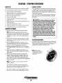
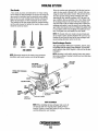
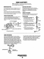
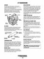
WARNING LIGHTS, ALARMS &CIRCUIT BREAKER
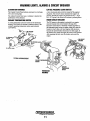
ALTERNATOR WARNINGS
LOW OIL PRESSURE ALARM SWITCH
The Captain Control Panel indicates alternator low discharge
with a red warning light
The Admiral Control Panel uses a voltmeter to monitor the
performance of the alternator.
A low oil pressure alarm switch is located off the engine's
oil gallery. This switch's sensor monitors the engine's oil
pressure. Should the engine's oil pressure fall to 5 -10 psi
(0.4 - 0.7 kg/cm2), this switch will activate a pulsating alarm.
COOLANT TEMPERATURE SWITCH
ENGINE CIRCUIT BREAKER
A coolant temperature switch is located on the thermostat
housing. This switch will activate a continuous alarm if the
coolant's operating temperature reaches approximately
210°F (99°C).
The DC harness on the engine is protected by an enginemounted manual reset circuit breaker (20 amps DC).
Excessive current draw or electrical overload anywhere in
the instrument panel wiring or engine wiring will cause the
breaker to trip. In this event most engines will shut down
because the opened breaker disconnects the fuel supply. If
this should occur, check and repair the source of the problem.
After repairing the fault, reset the breaker and restart the
engine.
TO CONTROL PANEL
TYPICAL ARRANGEMENT
<
COOLANT TFIIIIPFI<llITIIIRI:\
SEND OR
THERMOSTAT
ASSEMBLY
Engines & Generators
11
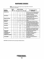
MAINTENANCE SCHEDULE
A WARNING: Never attempt to perform any service while the engine is
running. Wear the proper safety equipment such as goggles and gloves, and
use the correct tools for each job. Disconnect the battery terminals when
servicing any of the engine's DC electrical equipment.
NOTE: Many of the following maintenance jobs are simple but others are more
difficult and may require the expert knowledge of a service mechanic.
SCHEDULED
MAINTENANCE
Fuel Supply
CHECK
EACH
DAY
HOURS OF OPERATION
50
100 250
500
750 1000 1250
EXPLANATION OF SCHEDULED
MAINTENANCE
Diesel No.2 rating of 45 cetane or higher.
Fuel/Water Separator
0
0
Engine Oil Level
0
Oil level should indicate between
dipstick.
Coolant Level
0
Check at recovery tank; if empty, check at manifold.
Add coolant if needed.
0
Inspect for proper tension (3/8" to 112" deflection)
and adjust if needed. Check belt edges for wear.
Drive Belts
Check for water and dirt in fuel (drain/replace filter
if necessary).
weekly
Visual Inspection of Engine
0
NOTE: Please keep engine surface clean. Dirt
and oil will inhibit the engine's ability to
remain cool.
Fuel Filter
Starting Batteries
(and House Batteries)
0
0
0
0
Check for fuel, oil and water leaks. Inspect wiring
and electrical connections. Keep bolts & nuts tight.
Check for loose belt tension.
Initial change at 50 hrs, then change every 250 hrs.
Every 50 operating hours check electrolyte levels
and make sure connections are very tight. Clean off
excessive corrosion.
0
0
Heat Exchanger Zinc Anode
0
Fuel/Water Separator
Engine Hoses
0
weekly
Engine Oil (and filter)
Exhaust System
0
MAX. and LOW on
0
0
0
0
(] 0
0
0
0
0
0
0
0
0
0
0
0
0
0
or
0
0
Initial engine oil & filter change at 50 hrs., then
change both every 100 hours.
0
Inspect zinc anode, replace if needed, clear the heat
exchanger end of zinc anode debris.
0
0
Change every 200 hours.
0
Engines & Generators
12
Initial check at 50 hrs., then every 250 hrs. Inspect
for leaks. Check anti-Siphon valve operation. Check
the exhaust elbow for carbon and/or corrosion
buildup on inside passages; clean and replace as
necessary. Check that all connections are tig ht.
Hose should be hard & tight. Replace if soft or
spongy. Check and tighten all hose clamps.
MAINTENANCE SCHEDULE
NOTE: Use the engine hour meter gauge to log your engine hours or record your
engine hours by running time.
SCHEDULED
MAINTENANCE
CHECK
EACH
DAY
HOURS OF OPERATION
50
Raw Water Pump
100 250
0
Coolant System
Electric Fuel lift Pump
SOD
EXPLANATION OF SCHEDULED
MAINTENANCE
750 1000 1250
0
0
Remove the pump cover and inspect impeller, gasket, cam and cover for wear. Check the bearings
and seals (the shaft can turn, but not wobble).
Lubricate when reassembling.
Drain. flush, and refill cooling system with
appropriate antifreeze mixture compatible with
various cooling system metals.
0
0
0
0
0
0
Periodically check the wiring connections and
inspect the fuel line connections.
Inlet Fuel Filter
0
0
0
0
0
0
Replace.
DC Alternator
0
0
0
*Fuellniectors
Check DC charge from alternator. Check the
mounting bracket; tighten electrical connections.
Check and adjust injection opening pressure and
spray condition (see ENGINE ADJUSTMENTS).
0
*Starter Motor
0
0
*Preheat Circuit
0
0
*Englne Cylinder
Compression
D
0
Check solenoid and motor for corrosion. Remove
and lubricate. Clean and lubricate the starter motor
pinion drive.
Check operation of preheat solenoid. Remove and
clean glow plugs; check resistance (4-6 ohms).
Reinstall with anti seize compound on threads.
Check compression pressure and timing
(see Engine Adjustments).
*Torque Cylinder Head
Hold-down bolts
0
0
0
At first 50 hours. then every 500 hours
(see ENGINE ADJUSTMENTS).
*Adjust the Valve Clearances
0
0
0
Adjust Valve Clearances
(see ENGINE ADJUSTMENTS).
0
Remove. have profeSSionally cleaned and
pressure tested.
"Heat Exchanger
*WESTERBEKE recommends this service be performed by an authorized mechanic.
Engines & Generators
13
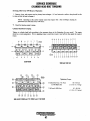
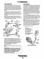
FUEL SYSTEM
DIESEL FUEL
Use No.2 diesel fuel with a cetane rating of 45 or higher. Do
not use kerosene or home heating fueL
FUEL FILTER/WATER SEPARATOR
Aprimary fuel filter of the water separating type must be
installed between the fuel tank and the engine to remove
water and other contaminants from the fuel before they can
be carried to the fuel system on the engine.
Most installers include a fuel filter/water separator with the
installation package as they are aware of the problems that
contaminants in 'the fuel can cause.
A typical fuel filter/water separator is il1ustrated below. This
is the Raycor Model 500 MA. Keep in mind that if a water
separator type filter is not installed between the fuel supply
tank and engine-mounted fuel system, any water in the fuel
will affect the fuel pump, engine filter, and injection equipment. The owner/operator is responsible for making certain
the fuel reaching the engine's injection equipment is free of
impurities. This process is accomplished by installing and
maintaining a proper fuel filter/water separator.
FUEL FILTERS
The fuel injection pump and the fuel injectors are precisely
manufactured and they must receive clean diesel fuel, free
from water and dirt. To ensure this flow of clean fuel, the fuel
must pass through at least two fuel filters, a fuel filter/water
separator and the engine's spin-on fuel filter. Visually inspect,
clean, and change these filters according to the maintenance
schedule in this manual.
A WARNING: Shut off the fuel valve at the tank
when servicing the fuel system. Take care in catching
any fuel that may spill. DO NOT allow any smoking,
open flames or other sources of fire near the fuel system when servicing. Ensure proper ventilation exists
when servicing the fuel system.
TYPICAL
FUEL
FILTER
LOOSEN FITTING - - - - - l ' - A
WHEN PRIMING
FILL FILTER
The fuel injection pump is a very important component of
the diesel engine, requiring the utmost care in handling. The
fuel injection pump has been thoroughly bench-tested and the
owner-operator is cautioned not to attempt to service it. If it
requires servicing, remove it and take it to an authorized fuel
injection pump service facility. Do not attempt to disassemble and repair it.
SPIN ON
Changing The Fuel Filter
0
FUEL FILTER
#24363
1. Shut off the fuel supply.
2. Loosen the fuel filter, turning counterclockwise with a
filter wrench. Place the used filter in a container for proper
disposal.
3. Using a rag, wipe clean the sealing face on the housing
bracket so the new filter can be seated properly.
4. Lightly oil the sealing O-ring on the new filter. To reinstaJ], tum the filter assembly counterclockwise carefully
until the a-ring contacts the sealing surface of the housing
bracket. Tum 213 further with the filter wrench.
5. The key-on preheat sequence will operate the fuel lift
pump and quickly fill the new filter. It is also poSsible to
hand prime ~he filter using the lever on the top.
6. Run the engine and inspect the filter for fuel leaks.
FUEL LIFT PUMP
Periodically check the fuel connections to and out of the
pump and make sure that no leakage is present and that the
fittings are tight and secure. The DC ground connection at
one of the pump's mounting bolts should be clean and well
securedbi the mounting bolt to ensure proper pump operations.
When energized thru the preheat circuit, the fuel lift pump
will purge air from the fuel system and provide a continuous
flow of fuel as the engine is running.
INLET FUEL FILTER
To ensure clean fuel enters the fuel lift pump, there is an
in-line filter at the incoming fuel line. This filter should be
replaced every 200 operating hours.
Engines & Generators
14
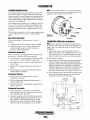
COOLING SYSTEM
FRESH WATER COOLING CIRCUIT
CHANGING COOLANT
NOTE: Refer to the ENGINE COOLANT page for the
recommended antifreeze and water mixture to be used as
the fresh water coolant.
The engine's coolant must be changed according to the
MAINTENANCE SCHEDULE. If the coolant is allowed to
become contaminated, it can lead to ovetbeating problems.
Fresh water coolant is pumped through the engine by a
circulating pump, absorbing heat from the engine. The
coolant then passes through the thermostat into the manifold,
to the heat exchanger where it is cooled and returned to the
engine block via the suction side of the circulating pump.
When the engine is started cold, external coolant flow is
prevented by the closed thermostat (although some coolant
flow is bypassed around the thermostat to prevent the exhaust
manifold from overheating). As the engine warms up, the .
thermostat gradually opens, allowing full flow of the engine's
coolant to flow unrestricted to the external portion of the
cooling system.
Coolant Recovery Tank
A
CAUTION: Proper cooling system maintenance is
,t:riflcal; a substantial number of engine failures can be
traced back to cooling system corrosion.
Drain the engine coolant by removing the drain plug on the
engine block and opening the manifold pressure cap. Flush
tQe ,system with fresh water, then reinstall the drain and start
the refill process. Refer to the illustration below.
NOTE: The drain petcock on the heat exchanger can also be
used to help drain engine coolant.
A WARNING: Beware of the hot engine coolant.
A coolant recovery tank allows for engine 'Coolant expansion
and contraction during engine operation,:'wjthout any
significant loss of coolant and without introducing air into
the cooling system. This tank should be located at or above
the engine manifold level and should be easily accessible.
Wear protective gloves.
Refilling the Coolant
COOLANT
RECOVERY
TANK
NOTE: PeriodicaUy check the condition of the manifold
pressure cap. Ensure that the upper and lower rubber seals
are in good condition and check that the vacuum valve opens
and closes tightly. Carry a spare cap.
SEAL
After replacing the engine block drain plug, close the heat
exchanger's coolant petcock. Then run !he engine at idle and
slowly poor clean, premixed coolant into the manifold.
Monitor the coolant in the manifold and add as needed. Fill
the manifold to the filler neck and install the manifold
pressure cap.
Remove the cap on the coolant recovery tank and fill with
coolant mix to halfway between LOW and MAX and replace
the cap. Run the engine and observe the coolant expansion
flow into the recovery tank.
After checking for leaks, stop the engine and allow it to cool.
Coolant should draw back into the cooling system as the
engine cools down. Add coolant to the recovery tank if
needed and check the coolant in the manifold. Clean up any
spilled coolant.
TO COOLANT
RECOVERY TANK
KEEP THE
COOLANT PASSAGE
CLEAR
FROM COOLANT
RECOVERY TANK
COOLANT EXPANSION
CHECKING THE PRESSURE CAP
Enfline! & Generators
15
,/PRESSURE
,CAP
COOLING SYSTEM
THERMOSTAT
RAW WATER INTAKE STRAINER
A thennostat, located near the manifold at the front of the
engine, controls the coolant temperature as the coolant
continuously flows through the closed cooling circuit. When
the engine is first started, the closed thennostat prevents
coolant from flowing (some coolant is by-passed through a
hole in the thennostat to prevent the exhaust manifold from
overheating). As the engine wanns up, the thennostat
gradually opens. The thennostat is accessible and can be
checked, cleaned, or replaced easily. Cany a spare thennostat
and gasket
NOTE: Always install the strainer at or below the waterline so
the strainer will always be self-priming.
A clean raw water intake strainer is a vital component of the
engine's cooling system. Include a visual inspection of this
strainer when making your periodic engine check. The water
in the glass should be clear.
Perfonn the following maintenance after every 100 hours of
operation:
1. Close the raw water seacock.
2. Remove and clean the strainer filter.
3. Clean the glass.
4. Replace the washer jf necessary.
5. Reassemble and install the strainer.
6. Open the seacock.
7. Run the engine and check for leaks.
Replacing the Thermostat
Remove the cap screws and disassemble the thennostat
housing as shown. When installing the new thennostat and
gasket, apply a thin coat of sealant on both sides of the
gasket before pressing it into place. Do not over-tighten the
cap screws.
Run the engine and check for nonnal temperatures and that
there are no leaks at the thennostat housing.
NOTE: Also follow the above procedure after having run hard
aground.
If the engine temperature gauge ever shows a higher than
nonnal reading, the cause may be that silt, leaves or grass
may have been caught up in the strainer, slowing the flow of
raw water through the cooling system.
SEALlNG~~~-
WASHER
INSPfCTAND
CLEAN EVERY
100 HOURS
~:(
TYPICAL RAW WATER STRAINER
(OWNER INSTALLED)
TEMPERATURE
SENDER
INCOMING
RAW WATER
THERMOSTAT ASSEMBLY
(TYPICAL)
SEACOCK
Engines & Generators
16
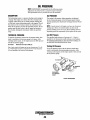
COOLING SYSTEM
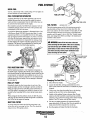
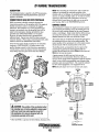
RAW WATER PUMP
Changing the Raw Water Pump Impeller
The raw water pump is a self-priming, rotary pump with a
non-ferrous housing and a Neoprene impeller. The impeller
has flexible blades which wipe against a curved cam plate
within the impeller housing, producing the pumping action.
On no account should this pump be run dry. There should
always be a spare impeller and impeller cover gasket aboard
(an impeller kit). Raw water pump impeller failures occur
when lubricant (raw water) is not present during engine
operation. Such failures are not warrantable, and operators
are cautioned to make sure raw water flow is present at startup. The raw water pump should be inspected periodically for
brokeno! tom impeller blades. See MAINTENANCE
SCHEDULE.
Close the raw water intake valve. Remove the pump cover
and, with the aid of two small screwdrivers, carefully pry the
impeller out of the pump. Install the new impeller and gasket
Move the blades to confonn to the curved cam plate and
push the impeller into the pump's housing. When
assembling, apply a thin coating of lubricant to the impeller
and gasket. Open the raw water intake valve.
A CAUTION: If any of the vanes have broken off the
impeller, they must be found to prevent blockage in the
cooling circuit. They often can be found in the heat
exchanger or in the discharge fitting of the pump.
NOTE: Should a failure occur with the pump s iliternal parts
(seals and bearings), it may be more cost efficient to
purchase a new pump and rebuild the original pump as a
spare.
RAW WATER PUMP
AIR INTAKE
NOTE: To operate efficiently a diesel engine must intake a
continuous volume ofclear air. Hard starting, an erratic idle,
and black e¥zaust smoke are all symptoms of a restricted air
intake.
ALIGN WITH THE
SLOT IN THE SHAFT
I
RAW WATER IN /
l
'INSPECTION: CHECK ATTHE BASE OF
EACH BLADE BY BENDING VIGOROUSLY.
REPLACE THE IMPELLER IF THERE
ARE ANY CRACKS.
WHEN INSTALLING: TAKE CARE TO ALIGN
THE IMPELLER KEYWAY WITH THE SHAFT
KEY. FOLD THE IMPELLER BLADES IN
EITHER DIRECTION (THEY WILL TURN IN
THE CORRECT POSITION WHEN THE
PUMP STARTS).
APPLY LIQUID SOAP
AT ASSEMBLY
Engines & Generators
17
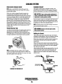
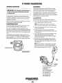
COOLING SYSTEM
Zinc Anode
If the zinc anodes need replacement, hold the hex boss into
which the zinc anode is threaded with a wrench while loosening the anode with another wrench. This prevents the hex
boss from possibly tearing off the exchanger shell. After
removing the Zinc, note the condition Qf it If the zinc is in
poor condition, there are probably a lot of zinc flakes within
the exchanger. Remove the end of the heat exchanger and
clean the inside of all zinc debris. Always have a spare heat
exchanger end gasket in case the present one becomes damaged when removing the end cover. Replace the gasket (refer
tc your engine model's heat exchanger end gasket part number), O-ring and cover, and install a new zinc anode.
A zinc anode, or pencil, is located in the raw water cooling
.circuit within the heat exchanger. The purpose of having the
zinc ~ode is to sacrifice them to electrolysis action taking
place ill the raw water cooling circuit, thereby reducing the
effects of electrolysis on other components of the system.
The condition of the zinc anode should be checked monthly
and the anode cleaned or replaced as required. Spare anodes
should be carried on board.
NOTE: The threads of the zinc anodes are pipe threads and
do ,not require sealant. Sealant should not be used as it may
insulate the zinc from the metal of the heat exchanger housing preventing electrolysis action on the zinc.
Heat Exchanger Service
REPLACE
NEW
REPLACE
ZINC ANODES
After approximately 1000 hours of operation, remove, clean
and pressure test the engine's heat exchanger. (A local automotive radiator shop should be.able to clean and test the heat
exchanger.)
CLEAN AND
REUSE
NOTE: Operating in silty and/or tropical waters may require
that a heat exchanger cleaning be perfonned more often than
every 1000 hours.
~OTE: E~ectrolysis action is the result of each particular
uzstallation and vessel location; not that of the engine.
IR BLEED
PETCOCK
ZINC ANODE
DO NOT USE SEALANT
ON THE THREADS
TYPICAL HEAT EXCHANGER
ASSEMBLY
COVER
SECURING
BOLT
WATER
INSPECT
BOTH ENDS
CLEAN our EVERY DRAIN
100 HOURS
CL'fAN OUT DEBRis
HEAT EXCHANGER
NOTE: When installing the heat exchanger end covers. Be
sure that the end cover securing bolt's sealing O-ring is
installed. Failure to install this sealing O-ring can result in
end plate failure/sea water leakage.
Engines & Generators
18
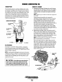
ENGINE LUBRICATING OIL
-
DESCRIPTION
ENGINE Oil CHANGE
The lubricating system is a pressure feeding system using
an oil pump. The engine oil is drawn from the oil sump by
the oil pump, which drives the oil, under pressure, through
the oil filter, oil cooler and various lubricating points in the
engine. 'The oil then returns to the oil sump to repeat the
continuous cycle. When the oil pressure exceeds the speci, fied pressure, the oil pushes open the relief valve in the oil
pump and returns to the oil sump, keeping the oil pressure
within its specified range.
LUBRICATION DIAGRAM
OIL PRESSURE
RELIEF VALVE
OIL PUMP
OILDRArN-~""W
OIL PRESSURE
The engine's oil pressure, during operation, is indicated'
by the oil pressure gauge on the instrument panel. During
nonnal operation, the oil pressure will range between 40 and
60 psi (2.8 and 4.2 kglcm2).
1. Draining the Oil Sump. Discharge the used oil througn
the sump drain hose (attached to the front of the engine)
while the engine is wann. Drain the used oil completely,
replace the hose in its bracket, and replace the end cap
securely.
NOTE: Thread size for the lube oil drain hose capped end
is 114NPT.
Always observe the used oil as it is removed. A
yellow/gray emulsion indicates the presence of water in
the oil. Although this condition is rare, it does require
prompt attention to prevent serious damage. Call a
qualified mechanic should water be present in the oil.
Raw water present in the oil can be the result of a fault in
the exhaust system attached to the engine and/or a
siphoning of raw water through the raw water cooling
circuit into the exhaust, filling the engine. This problem
is often caused by the absence of an anti-siphon valve, its
poor location or lack of maintenance.
2. Replacing the Oil Filter. When removing the used oil
filter, you may find it helpful and cleaner to punch a hole
in the upper and lower portion of the old filter to drain
the oil from it into a container before removing it. This
helps to lessen spillage. A small automotive filter wrench
should be helpful in removing the old oil filter.
NOTE: Do not punch this hole without first loosening the
jilter to make certain it can be removed.
Place some paper towels and a plastic bag around the
filter when unscrewing it to catch any oil left in the filter.
(Oil or any other fluid on the engine reduces the engine's
cooling ability. Keep your engine clean.) Inspect the old
oil filter as it is removed to make sure that the rubber
sealing gaSket comes off with the old oil filter. If this
rubber sealing gasket remains sealed against the filter
bracket, gently remove it.
NOTE: A newly started, cold engine can have an oil pressure
reading up to 60 psi (4.2 kglcm 2). A warmed engine can have
an oil pressure reading as low as 35 psi (25kg/cm2). These
readings will vary depending upon the temperature of the
engine and the rpms.
..
amm-11/16"
SOCKET
A
CAUTION: oD not allow two Dr more brands of
engine oil to mix. Each brand contains its own additives: additives of different brands could react in the
mixture to produce properties harmful to your engine.
Engines & Generators
, 19
ENGINE LUBRICATING OIL
When installing the new oil filter element, wipe the filter
gasket's sealing surface on the bracket free of oil and
apply a thin coat of clean engine oil to the rubber gasket
on the new oil filter. Screw the filter onto the threaded oil
filter nipple on the oil filter bracket, and then tighten the
filter firmly by hand..
NOTE: The engine oil is cooled by engine coolant flowing
through passages in the oil jilter bracket housing assembly.
A WARNING: Used engine oil contains harmful
contaminants. Avoid prolonged skin contact. Clean skin
and nails thoroughly using soap and water. Launder Dr
discard clothing Of rags containing used oil. Discard
used oil properly.
3. Filling the Oil Sump. Add new oil through the oil filler
cap on the top of the engine or through the side oil fill.
Mter refilling, run the engine for a few moments while
checking the oil pressure. Make sure there is no leakage
around the new oil filter or from the oil drain system, and
stop the engine. Then check the quantity of oil with the
lube oil dipstick. Fill to, but not over the high mark on
the dipstick, should the engine require additional oil.
ENGINE OIL
Use a heavy duty engine oil with an API classification of CF,
CG-4, CHA or CI-4. Change the engine oil after an initial 50
hours ofbreak-in operation, and every 100 hours of operation
thereafter. For reconnnended oil use SAE 15W-40
(oil viscosity). WESTERBEKE reconnnends the use of
synthetic oil.
NOTE: Generic jilters are not recommended, as the
material standards or diameters of important items on
generic parts might be entirely different from genuine
parts. Immediately after an oil jilter change and oil fill,
run the engine to make sure the oil pressure is nonnal
and that thef¥l are n~o oil leaks around the new oil filter.
Engines & Generators
20
REMOTE OIL FILTER (OPTIONAL)
JNSTALLATION
NOTE: Westerbeke is lWt responsible for engine failure due to
incorrect installation of the Remote Oil Filter.
!fhls popular accessory is used to relocate the engine's oil filter from the engine to a more convenient location such as an
~ngine room bulkhead.
.
NOTE: Refer to ENGINE OIL CHANGE in this rna:rw.alfor
instructions on removing the oil filter.
'lro install, 'simply remove the engine oil filter and thread on
WBSTERBEKB's remote oil filter kit as shown. Always
1nstall this kit with the oil filter facing down as illustrated.
Contact your WESTERBEKB dealer for more information.
A CAUTION: It is vital to Install the oil lines correctly.lf the 011 flows In the reverse direction, the by..
pass valve in the filter assembly will pf!1vent the oil
from reaching the engine causing an Intemal engine
failure. If there is no 011 pressure reading, shutdown
immediately and check the hose,Cirmnirlcti'ons.
APPLY A THIN COAT OF ClEAN OIL TO THE O·RING WHEN
INSTALLING THIS KIT. THREAD THE KIT ON, THEN HAND
TIGHTEN AN AODlTIONAL 3/4 TURN AFTER THE O·RING
CONTACTS THE BASE.
THE IN CONNECTION HOSE
MUST ATTACH TO THE OUT
CONNECTION ATTl1E
*---RI'MO'TI' Oil FILTER.
THE OUT CONNECTION
MUST ATTACH TO THE IN
CONNECTION AT THE
REMOTE Oil FILTER.
APPLY A THIN COAT OF CLEAN OIL TO THE FIlTER
GASKET WHEN INSTALLING. AFTER TliE FILTER
CQ.NTACTS IHE BASE, TIGHTEN IT AN ADDITIONAL'
f-.M'IWESTERBEKE
i Engines & Generators
21
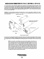
WATER HEATER CONNECTION KIT (71B & C, 82B FOUR, & 107 B & C)
The models refered to in this manual are equipped with connections for the plumbing of engine freshwater coolant
to a domestic hot water heater. One connection (to) is located on the lower side ofthe exhaust manifold. The other
connection (return) is located on the center outer surface of the heat exchanger. Both of these connections have
square head 1/2 N.P.T. plugs in them to plumb a domestic hot water heater into the engine's freshwater system.
Remove both of these plugs and install the appropriate hose nipple 1/2 N.P.T. x 3/4 I.D. to route hose to and return
from the domestic water heater.
Installation: The heater should be mounted conveniently either in a high or low position in relation to the engine,
so that the connecting hoses from the heater to the engine can run in a reasonably direct line without any loops
which might trap air.
Air Bleed Petcock
\
\ , "Heat Exchanger
HEATER BELOW ENGINE
Hoses should rise continuously from their low point at the heater to the engine so that trapped air will rise naturally
from the heater to the engine. If trapped air is able rise to the heater, then an air bleed petcock must be installed
at the higher fitting on the heater for bleeding air while filling the system. Avoid loops in hose runs which will trap
air.
NOTE: If any portion of the heating circuit rises above the engine's own pressure cap,
then a pressurized (aluminum) remote expansion tank must be installed in the circuit to
become the highest point. The remote expansion tank's part number is 24177. Tee the
remote expansion tank into the heater circuit at the heater connection, choosing the
higher of the two for the return. Tee right at the heater and plumb a single line up to the
tank's location and the other back to the engine's retUrn. install the remote expansion
tank in a convenient location such as In a sail locker so the fresh water coolant level can
easily be checked. The remote expansion tank will now serve as a check and system fill
point. The plastic coolant recovery tank is not used when the remote expansion tank kit
is installed, since this tank serves the same function.
Engines & Generators
22
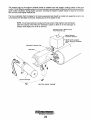
The pressure cap on the engine's manifold should be installed once the engine's cooling system is filled with
coolant. Finish filling the cooling system from the remote tank once the system is filled and is free of air and exhibits
good coolant circulation. During engine operation, checking the engine's coolant should be done at the remote
tank and not at the engine manifold cap.
The hose connection from the heater to the remote expansion tank should be routed and supported so as to rise
continuously from the heater to the tank, enabling any air in the system to rise.
NOTE: An air bleed petcock is located at the top center of the engine's heat exchanger.
Open this petccek when filling the freshwater system to allow air in the exchanger to
escape. Close tightly once all air is removed.
Pressure Cap is Rated Lower
than Manifold Cap
Heater Coils Located
Above Manifold Pressure
Cap
\
\
'",,~eat Exchanger
HEATER ABOVE ENGINE
Engines & Generators
23
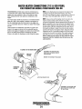
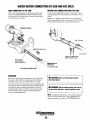
WATER HEATER CONNECTIONS (71 C & 828 FOUR)
FOR PRODUCTION MODELS FROM MARCH 2004 ON
NOTE: An air bleed petcock is located on the engine:V heat
exchanger and on the thermostat housing. Open these
petcocks when filling the engine s coolant system to allow air
to escape. Close both tightly after all the air is removed.
WESTERBEKE provides easy access for connecting to an
on-board hot water system. These connections allow for the
engines hot water (coolant) to flow to the ships hot water
tank, heating the fresh water and then cycling back to the
engine.
The water heater should be mounted in a convenient location
either in a high or low position in relation to the engine, so
that the connecting hoses from the heater to the engine can
run in a reasonably direct line without any loops which might
trap air.
Hoses should rise continuously from their low point at the
heater to the engine so that air will rise naturally from the
heater to the engine. If trapped air is able to rise to the heater,
then an air bleed petcock must be installed at the higher
fitting on the heater for bleeding air while filling the system.
NOTE: If any portion 0/ the heating circuit rises above the
engine S closed cooling system pressure cap, then a
pressurized (aluminum) remote expansion tank. (Kit #024177)
must be installed in the circuit to become the highest point.
Tee the remote expansion tank into the heater circuit, choosing the higher a/the two connections/or the return. Tee at
the heater; and plumb a single line up to the tanks location
and the other back to the engine's return. Install the remote
expansion tank in a convenient location so the fresh water
coolant level can easily be checked. The remote expansion
tank. will now serve as a check and system fill point. The
plastic coolant recovery tank is not used when the remote
expansion tank kit is installed, since this· tank serves the
same function.
TD CONNECT TO THE WATER HEATER
DISCONNECT THE EXISTING HOSE
AND ATTACH THE HEATER HOSE AT
THIS COUPLING
AIR BLEED
PETCOCK
\
REMOVE THE EXISTING BY-PASS HOSE
THERMOSTAT
HOUSING
DISCONNECT THE EXISTING HOSE
AND ATTACH THE HEATER HOSE
TO THIS FITTING.
Engines & Generators
24
WATER HEATER CONNECTION KIT (638 AND 63C ONLY)
HOSE CONNECTION TO THE TANK
RETURN HOSE CONNECTION FROM THE TANK
Remove the hex head plug at the thermostat assembly and
install the WATER HEATER CONNECTION KIT. Attach
the heater hose to the water heater connection kit and check
that all connections are tight.
Locate the hose and piping that comes off the engines fresh
water pump and cut into the smaller hose that leads to the oil
cooler.
Install the 'T' fitting, reconnect the cooler hose and install
the hot water tank return hose to the bottom of the "T' fitting
as shown below. Make certain all connections are tight.
THERMOSTAT HOUSING
5/8" T FITTING
TO OIL COOLER
A7TACH HOT WATER HOSE
FROM HOT WATER TANK.
MAKE CERTAIN
THE RESTRICTOR
NIPPLE IS INSTALLED.
OWNER INSTALLED
HEATER HOSE
TO HOT WATER TANK.
WATER HEATER CONNECTION KIT
OPERATION
A CAUTION: Bewam of the hot engine coo/ant,
Remove the manifold cap and replace any lost coolant. Run
the engine at idle (1800 rpm for generators) with the heat
exchanger petcock open, slowly add coolant as needed.
wear proper gloves.
Once coolant flows from the petcock, close it and replace the
manifold cap. When circulation is present to and from the hot
water tank (feel hoses), recheck the manifold-it should be
topped off with coolant. Also fill the coolant recovery tank
half fulL With the engine running, inspect for leaks and
check for normal temperature.
A WARNING: With the engine running, stay clear of
the drive belts. Generator· keep ben guards in place.
NOTE: For additional information on the proper installation
of your hot water system, refer to your engine/generator
operators manual or contact your WESTERBEKE dealer.
Engines & Generators
25
WIRING DIAGRAM
Btu
r~11
I
-
'A~'~
I~
- UI MOon.S)
E
I~1
1
$EE HOT[ 2,
I
.J
,,
I
LIFT PUMP
IIOTE: An on-off switch
should be installed In this
circuit to disconnect the
starter from the battery in
811 emergency and when
leaving the .boat Twelve
volt engine staffers
typically draw 200 to 300
amps when cranking, A
switch with a continuous
rating of 175 amps at 12
VDC will normally serve
this function, but a switch
must never be used to . I
"make» the starter circuit. I
=
;..
- :::
:.-
'2m'"
...
p
+
C
ALARM
SUllER
ADMIRAL
PANEL
WIRING DIAGRAM #39144
,
,
I
I
I
I
I
I
I
L----l,:~
,
,
I
"
'-------
CAPTAIN
PANEL
tlO lU
- - __________________ J
r--
-------
o
I
I
I
I
~tII
tl8
I
1
I
1
I
1
,,
,,
I
••
': L~::::::::::::±:~::::::~~::::::::::~~~====~~~J
tie eLl
.,8 aUI
,
::: :~:
l-.vIWESTERBEICE
, Enaines & Generators
26
-I
I
I
I
I
I
I
I
1
I
I
I
I
I
I
I
I
I
I
______'-_-_-_-_-_-_-_-_-_-_-1____ ..J
I
WIRING SCHEMATIC
+
SS~Rr
12 VDe
0
S'tdHR
~-------7;~~rl171------~'H~
I
~..
~_.....,.
"
~
------------1-----.
I
I
I,
___---:r~- ,
Pft(ItUT
T IS PROTECTED SY A
XCU$IYE CURRENT WILL
TItE eUILOER/OWNtR
SOL
IIISU"ED TO PREVEII
--;I'll I
-r
1.
I
A,N
Q/Ij,.orr
RESET CIRCuIT SR"'rR
THE SRU.KEIt 10 nl9' A
SURE THAT THE tNST
T eErrEE" ELECTRIC
SWITCH SHOULD BE INSTALtED BUWtEf,I TH£ 8A'fTrR,\, AN!) $TART£R TO
::f~O:H~5~T!=~~fr~~11"JNO:H I~;[::~=:" ~~O 1;H~~li~i~MgE~~f ¥~~i' rUH~T~~~ :CHnH~
SWITCH SHOUl!) HOi BE u-S£O TO ~j(E OR 8RtAf( THE (UICUIT,
AlHtUtATOA
J. THE PINK WIRt AT PlUG 1 IS UNUSED AND SHOULD
~--~1--r------------~~Gm---------~
at
Hi$UL,ATED. CAPU'N PAN£!. 0+11..1
4. THE GRAY WIRE AT PLUG 2 IS UNUSEO AIriII) StlQIJt.O BE INSULATED. "ONU"l PANE!. ONI,.Y.
p
_.
_
Fun
.....---~-~---------
PRES;QLIIE\LEECE-NEYILLE 99 AMP
All
ALI
NOTE,
'18E fOR BATTERY AnATC"MEIIY win NHD
TO BE U'.<'OEO TO AN • • AUGE HOW 10 GAUGE
114 BRN
#14 BRN
@
PRESTOl!IE 1 Z AMP
UNIVERSAL PROPULSlfrN
PREHouTE 51 AMP, AT
Al I
#14 GRA
CAPTAIN
PANEL
#14 PINK
t I 0 REO
# 14 LI,
lESIH 100 AMP
6L
ALT. @
!<ALE CONNECTOR
ON THIS SIO£
\1111
REO
WIRING SCHEMATIC #39144
t14 tT
MALE CONNECTOR
tTA.CHll!j
.RM
"
REO
A
BLU
'14 PHIK
~
011 THIS SlOE
_ _ _"'.~"f:B,!!,R.N
BL"
!l4 GSA
(NOT USED)
l!!J):
51 AMP, ALTERNATOR
sr ANDARO ALTERNATOR ON IHE
6;8 a, Be a, 716 01:. 826
I aee 11l. & loec 11l
tl4aU
14 RrO
CASE GH
I SCO"'''(CT JUWPU F¢fI
uS! WITH TWO eHT£AI£S
OPT IONAL AL TE RNA TORS ®
13!iA,
160 ...
.\\IAlblSU ON l'H£ W50S 6glV
19(1A
Gxr;tV
LESTU ALTERNATORS
H:g:::!V. 821CfV.
IOgVI
! IOSI:Vl
Engines & Generators
27
a,
GLOW PLUGS
Re--install the plugs in the engine and test them again. The
plugs should get very hot (at the terminal end) within 7 to 15
seconds. If the plugs don't heat up quickly, check for a short
circuit When reinstalling the glow plugs, use anti-seize
compound on the threads.
DESCRIPTION
The glow plugs are wired through the preheat solenoid.
When PREHEAT is pressed at the control panel this solenoid
should "click" on and the glow plug should begin to get hot.
INSPECTION
A WARNING: 00 not keep a g/owplug on for more
To inspect the plug, remove the electrical terminal cOJmections, then unscrew or unclamp each plug from the cylinder
head. Thoroughly clean each plug's tip and threads with a
soft brush and cleaning solution to remove all the carbon and
oil deposits. While cleaning, examine the tip for wear and
burn erosion; if it has eroded too much, replace the plug.
than 30 seconds.
GLOW PLUG TIGHTENING TORQUE
1.0· 1.5 M-KG (7 ·11 FT-LB)
I
TERMINAL END
TESTING
An accurate way to test glow plugs is with an ohmmeter.
Touch one prod to ·the glow plug's wire connection, and the
other t~ the body of the glow plug, as shown. A good glow
plug WIll have a 1.0 - 1.5 ohm resistance. This method can be
used with the plug in or out of the engine. You can also use
an multimeter to test the power drain (8 - 9 amps per plug).
TESTING WITH .
AN OHMMETER
PREHEAT ON
A
WARNING: These glow plugs will become very hot
to the touch. Be careful not to burn your fingers when
testing the plugs.
USING A
TEST LIGHT
GLOW PLUG
+
Engines & Generators
28
STARTER MOTOR
DESCRIPTION
The starter is a new type, small, light-weight and is called a
high-speed internal-reduction starter. The pinion shaft is
separate from the motor shaft; the pinion slides only on the
pinion shaft. A reduction gear is installed between the motor
shaft and a pinion shaft. The pinion sliding part is not
exposed outside the starter so that the pinion may slide
smoothly without becoming fouled with dust and grease. The
motor shaft is supported at both ends on ball bearings. The
lever mechanism, switch and overrunning clutch inner circuit
are identical to conventional ones.
J-E'----(M) TERMrNAL
IGNITION /
TERMINAL
SOLENOID
To test the ignition circuit, locate the ignition(s) terminal (it
is one of the small terminal studs and is wired to the ignition
circuit). Use a screwdriver, don't touch the blade, to jump
from that ignition terminal to the positive battery connection
terminal on the solenoid.
If the starter cranks, the fault lies with the ignition
circuit.
If the solenoid clicks but nothing happens, the starter
motor is probably faulty.
MOTOR
TYPICAL
STARTER MOTOR
REFER TO THE WIRING
DIAGRAM IN THIS MANUAL
TROUBLESHOOTING
A WARNING: The following emergency starting
SOLENOID
procedures must not be used with gasoline engines.
Sparks could cause an explosion and fire.
Prior to testing, make certain the ships batteries are at full
charge and that the starting system wiring connections
(terminals) are clean and tight. Pay particular attention to
the ground wire connections on the engine block.
To check the wiring, try cranking the starter for a few
seconds, never more than 10 seconds at a time, then run your
hand along the wires and terminals looking for warm spots
that indicate resistance. Repair or replace any trouble spots.
Using a multimeter, test the voltage between the positive
terminal stud on the start solenoid and the engine block
(ground).
If you read 12 volts, the starter is faulty.
">
IGNITION
TERMINAL
~
If nothing happens at all, the solenoid is not getting
current. Check the battery isolation switch and inspect the
wiring connections. it is also possible that the solenoid is
defective.
A WARNING: There will be arching and sparks will
fly when jumping terminals. Be certain the engine
space is free of potentially explosive fumes, especially
gasoline, and that there are 1!!1 flammable solvents Dr
materials stored nearby.
Engines & Generators
29
STARTER MOTOR
EMERGENCY START
A WARNING: When performing these procedures,
Corrosion to the starter brushes and/or the solenoid contacts
can cause the sporadic problem of the engine starting one
time but not another. If corrosion is the problem, the starter
will need to be rebuilt.
It is however, sometimes possible to get started by taping the
starter lightly with a small hammer.
With the battery switch off and no ignition,. tap lightly on the
starter/solenoid casing as shown, then try to start the engine.
position yourself safely away from the moving parts of
the engine in case the engine starts-up_ Also warn
other crew members of the danger.
CAREFULLY NOT TO HIT
/'
FITTINGS OR WIRE CONNECTioNS
I
(+) POSITIVE
)TERMINAL
-------,-'~""
~.--
~;:----~-(M)
TERMINAL
TAP LIGHTLY WHERE
\. INDICATED
IGNITION
TERMINAL
Test again by jumping the two large terminal studs. Hold the
screwdriver blade finnly between the studs. Do not allow the
screwdriver blade to touch the solenoid or starter casing, this
would cause a short.
A WARNING: There will be arching as the full
If that fails, tum the battery switch on and have a crew
member tum the ignition on and off rapidly as you tap again
with the hammer., This may loosen the brushes and allow
contact to start the engine. When you reach a repair facility,
the starter will need to be repaired.
starting current should be flowing thru the blade of
the screwdriver.
If the starter spins, the solenoid is faulty.
If the starter fails to spin, the motor is probably faulty.
If no arching occurred, there is no juice reaching the
solenoid.
SERVICE
WESTERBEKE uses a standard starter motor which can be
serviced or rebuilt at any starter motor automotive service
center,
If replacing the starter motor, make certain the new motor is
certified for marine use. Automotive starters do not meet
USCG standards. If in doubt, contact your WESTERBEKE
dealer.
NOTE: Starter motors are either inertia type or pre-engaged.
In the pre-engaged model, the solenoid also moves an arm
that engages the starter motor to the flywheel of the engine.
using a screwdriver to bypass the solenoid on such a starter
will run the motor without engaging the flywheel. Tum the
starter switch on to provide power to the solenoid. Hopefully
it will create enough magnetic field for the arm to move even
though the contacts inside the solenoid are bad.
TO REMOVE FOR SERVICE
1. Disconnect the negative battery cable.
2. If necessary, remove any components to gain full access
to the starter motor.
3. Label and disconnect the wiring from the starter. (Do not
allow wires to touch, tape over the terminals).
4. Remove the starter mounting bolts.
5. Remove the starter from the engine. In some cases the
starter will have to be turned to a different angle to clear
obstructions,
En Jines & Generators
-3D
DUAL OUTPUT ALTERNATORS
SPACER TO MOUNTING
BRACKET
DESCRIPTION
Dual output and high output alternators are available as
optional equipment on most WESTERBEKE engines. These
altemators can be installed during factory assembly or as
add-on equipment at anytime.
Dual alternators can be configured to charge two banks of
batteries at the same time or, using a battery selector switch,
charge each set of batteries separately.
TO
INSTALLATION
If an optional dual alternator has already been factory installed,
simply follow the WESTERBEKE wiring diagram and the
engine installation instructions.
If the new dual alternator is being added to an existing "in-
the-boat" engine, carefully follow the alternator installation
instructions below:
1. Disconnect the alternators negative cable from the
battery.
2. Remove the alternator and disconnect or tape off the
output [positive] cable. Do not reuse.
3. Install the new alternator.
4. Attach a new heavy gauge output cable[s] from the
alternator's output terminal [s). Using the cable sizes
indicated.
DUAL OUTPUT ALTERNATOR
[CHARGING ONE BATTERY]
UP TD-7.6'..---;c#4~W~rRE
12' #2 WIRE---UP TO 20'
#(lWIRE _
[ALWAYS USE FINE STRAND CABLE1
LENGTH REQUIRED
------iJPro
S. Make certain that the batteries negative post ground
cable to the engine block is the same heavy gauge as
the positive cable.
6. Mount the regulator to a flat surface in a cool dry
location.
a. Connect the black wire to the ground terminal on the
alternator.
BATTERY 1
A CAUTION: Do not connect any power source without first grounding the regulator.
b. Plug the 2-pin connector into the alternator, make
certain it is firmly seated.
c. The red "battery sense" wire should be connected to
the batteries positive [+] post [or the positive cable],
d. The brown wire "keyed ignition" is the key circuit
which actuates the regulator, this wire must connect
to a switched [+] 12 volt source. Refer to the
WESTERBEKE WIRING DIAGRAM for the proper
connection.
~;:::.....c=--
IJl(OlY.
~ONNECTS
;st.
Dual Pulleys
"BATTERY SENSE"
TO BATTERY POSITIVE POST
TO PINK AND
BLUE LEADS. THE PINK
,WIRE CONNECTS TO THE
'ALARM BUZZER. THE BLUE
WIRE CONNECTS TO THE
OIL PRESSURE SWITCH.
DUAL OUTPUT ALTERNATOR
[CHARGING TWO BATTERIES1
A variety of accessory pulleys for high powered and dual
charging alternators are available from your
dealer.
Engines & Generators
31
DUAL OUTPUT ALTERNATORS
TROUBLESHOOTING
Alternator Testing
NOTE: Before troubleshooting, make certain that the drive
The regulator is functioning properly and the batteries
are in good condition.
1. Test the voltage at the alternator plug with the engine
off-key on. The voltage at the alternator terminal F and
the voltage in the plug [blue wire F] from the regulator
should read the same.
2. Hold a screw driver close [112") to the alternator pulley.
If voltage is present you should feel the magnetic field. If
.not, the problem may be the brushes [wornJor the rotor
(open circuit].
3. Start the engine, at fast idle the output terminals should
indicate 14.2 volts [no load]. A reading of 12.6 would
indicate the alternator is not performing properly.
Apply a load such as an electric bilge pump, the voltage
should maintain at least 13.8 volts. 13 volts or less
indicates the alternator is faulty.
belts are tight and the batteries are in good condition.
Regulator Testing
The red "battery sensing" wire A connects to the battery, it
must always read battery voltage. If battery voltage is not
present, trace the wire for a bad connection.
The orange wire S should read 0 volts with the key off, 12
volts [approximately] with the key on. If the readings are
incorrect, trace the wire for a bad connection.
The blue wire F supplies current to the alternator fields, its
voltage will vary depending on the battery charge or actual
load/rpm. The readings can vary from 4 to 12 volts with the
key on, 0 volts with the key off.
KEY ON - NO VOLTAGE
REGULATOR IS DEFECTIVE
KEY OFF - BATTERY VOLTAGE
REGULATOR 15 DEFECTIVE
REGULATOR TEST POINTS AND PROPER VOLTAGE
Terminal/COlor
I Brown
A Red
5 Orange
F Blue
Alt. Output
Ignition Off
volts
12.6 volts
ovolts
ovolts
12.6 volts
o
Ignition On
2 -12 volts
12 volts
ovolts
10 ·11 volts
12 volts
NOTES:
Engine Running
14.2 volts
14.2 volts
6· holts
4 ·12 volts
14.2 volts
When the engine is first started, it takes a few moments
for the alternator to "kick in" and take the load. There
is a noticeable change in the sound of the engine and the
RPM gauge will excite.
D A slight whine is normal when running with a full load
on the alternator.
D When the alternator is producing high amperage, it will
become very hot.
D When replacing the alternator drive belts, always
purchase and replace dual belts in matched pairs.
Engines & Generators
32
DUAL OUTPUT ALTERNATORS
DESCRIPTION
5. Make certain that the batteries negative post ground cable
to the engine block is the same heavy gauge as the
positive cable.
6. Mount the regulator to a flat surface in a cool dry location.
a. Connect the black wires to the mounting bolt on the
alternator (ground)
Dual output and high output alternators are available as
optional equipment on most WESTERBEKE engines. These
alternators can be installed during factory assembly or as
add-on equipment at anytime.
Dual alternators can be configured to charge two banks of
batteries at the same time or, using a battery selector switch,
charge each set of batteries separately.
A
CAUTION: Do not connect any power source
without first grounding the regulator.
INSTALLATION
If an optional dual alternator has already been factory
installed, simply follow the WESTERBEKE wiring diagram
and the engine installation instructions.
If the new dual alternator is being added to an existing "inthe-boat" engine, carefully follow the alternator and regulator
instructions below:
1. Disconnect the alternators neg~tive cable from the battery.
2. Remove the alternator and disconnect or tape off the
output [positive] cable. Do not reuse.
3. Install the new alternator.
4. Attach a new heavy gauge output cable[s] from the
alternator's output terminal [s]. Using the cable sizes
indicated.
UP TO 6'
#4 WIRE
UP TO 12' #2 WIRE
,
UP TO 20' #0 WIRE
{ALWAYS USE FINE STRAND CABLE]
b. Plug the 2-pil'f connector into the alternator connection
and make certain it is fmnly seated.
c. The red "battery sense" wire should be connected to the
batteries positive [+] post [or the positive cable].
d. The brown wire "keyed ignition" is the key circuit
which actuates the regulator, this wire must connect
t«, a switched [+] 12 volt source. Such as the oil
pressure switch.
e. A brown wire from the electric tachometer connects to
the regulator.
Dual Pulleys
A variety of accessory pulleys for high powered and dual
charging alternators are available from your WESTERBEKE
dealer.
LENGTH REQUIRED
BALMAR 100 AMP AlTERNATOR
#14 BWElI14 PINK
IGNITIONB+
#14 BlACK/GROUND
#4 RED TO STARTING'
BATTERY 8+ WHEN
USING TWO BATTERIES
#14 RED
SENSE
#18 BROWN
#14 BWE/#14 PINK
IGNITiON B1' ~~:,,,,,,,
___
'14 BROWN'
NOTUSED
U0
MALE CONNECTOR
. TH'E!JDE\
o
'-
TACHOMETER
.;
114 BLUE
FIELD
---------
.#4 RED TO STARTING
'BA1TERY Bf WHEN
USING TWO BArrERIES.:'=-===::;::;;~!-i
-~-
~--
114BWE
FlEW
#14 WHITE
STATOR.
~ngineS & Generators
33
'...",WESTERBEKE
AlTERNATOR MOUNT (GROUND)
ALTERNATORS TESTING/TROUBLESHOOTING
SEE WIRING DIAGRAM
FOR WIRE CONNECTIONS
TO OPTIONAL ALTERNATORS
50AMP
ALTERNATOR
EXCITER
TERMINAL
l!.
NOTE: FOR CORRECT WIRING HARNESS CONNECTIONS TO THE ALTERNATOR,
REFER TO THE WIRING DIAGRAMS IN THIS MANUAL.
DESCRIPTION
VOLTAGE REGULATOR
The following infonnation applies to the standard alternators
that are supplied with WESTERBEKE'S Marine Engines
and Marine Generators.
The integral voltage regulator is an electronic switching
device which senses the system voltage level and switches
the voltage applied to the field in order to maintain a proper
system voltage.
ELECTRICAL CHARGING CIRCUIT
The regulator design utilizes all-silicon semi conductors and
thick-film assembly techniques. After the voltage has been
adjusted to the proper regulating value, the entire circuit is
encapsulated to protect the circuit and the components from
possible damage due to handling or vibration and moisture
encountered in a vessel.
The charging system consists of an alternator with a voltage
regulator, an engine DC wiring harness. a DC circuit breaker
and a battery with connecting cable and wires. Because of
the use of integrated circuits (Ie's), the electronic voltage
regulator is very compact and is mounted internally or on the
back of the alternator.
It is desirable to test the charging system (alternator and
voltage regulator) in the boat using the wiring harness and
electrical loads that are a pennanent part of the system.
In-boat testing will then provide the technician with an
operational test of the charging system as well as the major
components of the electrical system.
ALTERNATOR TROUBLESHOOTING
Use this troubleshooting section to determine if a problem
exists with the charging circuit or with the alternator. If it is
determined that the alternator or voltage regulator is faulty,
have a qualified technician check it.
LOW BATTERY/FAULTY CIRCUIT
ALTERNATOR DESCRIPTION
If the starter only moans or makes a clicking sound instead
of spinning the engine to life it is likely a low battery or a
faulty connection in the starting circuit and not an alternator
problem.
The stator is connected to a three-phase, full-wave bridge
rectifier package which contains six diodes. The bridge
converts the AC generated in the stator to a DC output for
battery charging and accessories such as a radio, heater,
lights, refrigerator, depth sounder, etc.
Power to the regulator and the field of the integral regulator
alternator is provided by the field diode (or diode trio)
package contained in the alternator.
These alternators produce a rated output of 50 or 51 amps.
Rated output is achieved at approximately 6000 alternator
rpm at an ambient temperature of75°F (23.8°C). The
alternators are designed to operate in an ambient temperature
range of 40° to 212°F (-400 to 100°C).
A simple test is to try starting again with a cabin light on, if
the light dims significantly or goes out, the battery is dead. If
the light remains bright, look for a poor connection in the
starting circuit.
A WARNING: A working alternator runs hot. a failed
i
alternator can become very hot. Do not touch the
alternator until it has cooled.
/"fIV'IWESTERBEKE
I Engines & Generators
34
ALTERNATORS TESTING/TROUBLESHOOTING
PRELIMINARY INSPECTION
3. Thrn off the engine. Inspect all wiring and connections.
Ensure that the battery terminals and the engine ground
connections are tight and clean.
4. If a battery selector switch is in the charging circuit,
ensure that it is on the correct setting.
S. 'furn on the ignition switch, but do not start the
engine.
6. Check the battery voltage. If the battery is in good
condition, the reading should be 12 to 13 volts.
Before starting the actual alternator and voltage regulator,
testing the following checks are recommended.
1. Make certain your alternator is securely mounted.
2. Check the drive belt for proper tension. Replace the belt
if it is worn or glazed.
3. Check that all terminals, connectors and plugs are clean
and tight. loose or corroded connections cause high
resistance and this could cause overcharging,
undercharging or damage to the charging system. Badly
corroded battery cables could prevent the battery from
reaching a fully charged condition.
4. Check the condition of the battery and charge if
necessary. A low or discharged battery may cause false
or misleading readings on the in-vessel tests.
NOTE: An isolator with a diode, a solenoid, or a battery
selector switch is usually mounted in the circuit to isolate
the batteries so the starting battery is not discharged
along with the house batteries. If the isolator is charging
the starting battery but not the house battery, the
alternator is Ok and the problem is in the battery
charging circuit.
MEASURING
BATTERY VOLTAGE
(IGNITION ON
ENGINE OFF)
TESTING THE ALTERNATOR
A
Testing The Output Circuit
CAUTION: Before starling the engine make
1. Connect the positive probe to the output terminal B and
cerlain that everyone Is clear of moving parts! Keep
away from sheaves and belts during test procedures.
connect the negative probe to the ground terminal E on
the alternator.
2. Wiggle the engine wiring harness while observing the
voltmeter. The meter should indicate the approximate
battery voltage, and should not vary. If no reading is
obtained, or if the reading varies, check the alternator
output circuit for loose or dirty connections or
damaged wiring.
3. Start the engine.
4. Repeat the same measurement, the negative probe to E,
the positive probe to B with the engine running. The
voltage reading should be between 13.5 and 14.5 volts.
If your alternator is over or under-charging, have it
repaired at a reliable service shop.
1. Start the engine.
2. After the engine has run for a few minutes, measure the
starting battery voltage at the battery terminals using a
multimeter set on DC volts.
a. If the voltage is increasing toward 14 volts, the
alternator is working; omit Steps 3 through 8 and go
directly to "Checking the Servic~ Battery".
b.Ifthe voltage remains around 12 volts, a problem
exists with either the alternator or the charging circuit;
continue with Steps 3 through 8.
5. If the previous test reads only battery voltage at
terminal B use the meter to measure the DC excitation
terminal. If 12 volts is not present at exciter terminal
R, inspect the wiring for breaks and poor connections.
Jump 12 volts from a 12 volt source (such as the
battery) and operate the alternator. If voltage output is
13-14 volts, then the alternator is OK.
MEASURING
BATTERY
VOLTAGE
ENGINE RUNNING
Enaloes & Generators
.35
ALTERNATORS TESTING/TROUBLESHOOTING
TESTING THE
OUTPUT CIRCUIT
ENGINE RUNNING
5. If no reading is obtained, an open exists in the
alternator-excitation lead or in the excitation circuit of
the regulator. Disconnect the lead from exe. terminal R.
Connect the positive multimeter probe to the excitation
lead and the negative multimeter probe to ground
terminal E. If the multimeter now indicates an
approximate battery voltage, the voltage regulator is
defective and must be replaced. If no voltage is
indicated, check the excitation circuit for loose or dirty
connections or damaged wiring.
TO STARTER
SOLENOIO
CHECKING THE SERVICE BATTERY
Check the voltage of the service battery. This battery should
have a voltage between 13 and 14 volts when the engine is
running. If not, there is a problem in the service battery
charging circuit. Troubleshoot the service battery charging
circuit by checking the wiring and connections, the solenoid,
isolator, battery switch, and the battery itself.
When the problem has been solved and before the alternator
is back in operation, take the time to tighten and clean the
terminal studs. Also clean the connecting tenninals from the
wiring harness.,
BATTERY
TESTING'. THE EXCITATION CIRCUIT
1. Connect the positive (+) multimeter probe to the
excitation terminal R on the alternator and the negative
(-) probe to the ground terminal E on the alternator.
2. Turn the ignition switch to the on position and note
the multimeter reading. The reading should be 1.3 to
2.5 volts (see illustration).
ALTERNATOR REPAIR
If tests indicate a failed alternator, it will need to be
disassembled and repaired. Any good alternator service
shop can do the job.
NOTE: WESTERBEKE'S Service Manual has detailed
instructions for the disassembly and repair of their
standard altemators.
BATTERY CARE
3. If the reading is between .75 and 1.1 volts, the
rotor field circuit probably is shorted or grounded.
4. If the reading is between 6.0 and 7.0 volts, the rotor
field circuit probably is open.
The minimum recommended capacity of the battery used in
the engine's 12 volt DC control circuit is 600-900 Cold
Cranking Amps (CCA).
Review the manufacturer's recommendations and then
establish a systematic maintenance schedule for your
engine's starting batteries and house batteries.
• Monitor your voltmeter for proper charging during
engine operation.
• Check the electrolyte level and specific gravity with a
hydrometer.
• Use only distilled water to bring electrolytes to a proper
level.
• Make certain that battery cable connections are clean and
tight to the battery posts (and to your engine).
'-w'IWESTERBEKE
IEnafnes & Generators
. ·36--
ENGINE TROUBLESHOOTING
The following troubleshooting table describes certain problems
relating to engine service, the probable causes of these problems, and the recommendations to overcome these problems.
Problem
No panel indications; fuel solenoid
or fuel pump is no! working (key switch
is on and PREHEAT button is depressed).
NOTE: The engine '8 electrical system is protected by a 20
ampere manual reset circuit breaker located on a bracket at
the back of the engine. The preheat solenoid is mounted on
the same bracket.
Probable Cause
VerificationJRemedy
1. Battery switch not on.
1. Check switch and/or battery connections.
2. 20-amp circuit breaker tripped.
2. Reset breaker; if breaker trips again, check preheat solenoid
circuit and check circuit for shorts to ground.
3. 10-amp breaker tripped on
preheat solenoid
3. Check the voltage both at and after the breaker on the
preheat solenoid.
4. Loose battery connections.
4. Check (+) connection to starter solenoid and (-) connection to
5. Preheat solenoid not operating.
5. Check solenoid "S" terminal for voltage.
1. Connection to solenOid faulty.
1. Check connection.
2. Gear shift not in neutrel.
2. Gear shift must be in neutral (see NEUTRAL SW/TCHunder
HURTH HSWTRANSMISSIONS).
3. Faulty switch.
3. Check switch with ohmmeter.
engine ground stud. Check battery cable connections.
START button is depressed, no starter
engagement.
4. Faulty solenoid.
4. Check thaI 12 volts are present at the solenoid connection.
5. Loose battery connections.
5. Check battery connections.
6. Low battery.
6. Check battery charge state.
START button is depressed; panel
indications OK; starter solenoid OK;
fuel solenoid not functioning.
1. Poor connections to fuel solerlOid.
1. Check connections.
2. Defective fuel solenoid.
2. Check that 12 volts are present at the (+) connection on the
fuel run solenoid.
Engine cranks, but does not
start, fuel solenoid energized.
1. Faulty fueling system.
1. Check that fuel valves are open.
1a. Check for air in fuel system. Bleed air from fuel system.
1b. Fuel filters clogged. Replace filters and bleed air from
fuel system.
2. Preheat solenoid faulty.
2. Check solenoid.
3. Low battery power.
3. Switch to combine house and start batteries.
3a. Replace batteries.
Engine can't be stopped.
Battery runs down.
1. Faulty DC alternator.
1. Remove Exc. connection at alternator, repair alternator.
2. Disconnect fuel shut-off cable.
2. Check connection at shut-off lever. Pull lever back to close
offthe fuel
3. Fuel nm solenoid will not de-en~rgize.
3. Manually disconnect the 12 volt connection to the fuel run
solenoid at the injection pump.
1. Oil pressure switch.
1. Observe if gauges and panel lights are activated when engine
is not running. Test the oil pressure switc~.
2. High resistance leak to ground.
2. Check wiring. Insert sensitive (0 - .25 amp) meter in battery
lines. (Do not start engine.) Remove connections and replace
after short is located.
3. Low resistance leak.
3. Check all wires for temperature rise to locate the fault.
4. Poor battery connections.
4. Check cable connections at battery for loose connections,
corrosion
5. DC altemator not cHarging
5. Check connections, check belt tension, test altemator. See
(tachometer not operating).
Battery not charging
DC ELECTRICAL SYSTEM/ALTERNATOR.
1. DC charge circuit faulty.
1. Pertorm DC voltage check of generator charging circuit See
Testing the BattelJl Charging Circuit
2. Check drive belt tension; alternator should furn freely. Check
2. Alternator drive.
for loose connections. Check output with voltmeter. Ensure 12
volts are present at the Exc. terminal.
(con.tinued)
Engines & Generators
37
ENGINE TROUBLESHOOTING
Problem
Probable Cause
Engine slows and stops.
Verification/Remedy
1. Fuel lift pump failure.
1. Fuel lift pump should make a distinct ticking sound. Replace
pump with spare.
2. Switches and/or wiring loose
2. Inspect wiring for short circuits and loose connections.
or disconnected.
Engine overheats/shuts down.
Inspect switches for proper operation.
3. Fuel starvation.
S. Check fuel supply, fuel valves, fuel lift pump.
4. 20 Amp circuit breaker tripping.
4. Check for high DC amperage draw during operation.
Ensure breaker is not overly sensitive to heat which would
cause tripping.
5. Exhaust system is restricted.
5. Check for blockage, collapsed hose, carbon buildup at
exhaust elbow.
6. Water in fuel.
6. Pump water from fuel tank(s); change filters and
bleed fuel system.
7. Air intake obstruction.
7. Check air Intake filter cartridge.
1. Raw water not circulating.
1. Raw water pump failure. Check impeller - replace.
2. Coolant not circulating.
2. Obstruction at raw water intake or raw water filter.
2a. Themnostat - remove and tesl in hot water.
Replace thermostat.
2b. Loss of coolant - check hoses, hose clamps, drain plug, etc.
for leaks.
2e. Broken or loose belts - tighten/replace.
2d. Air leak in system; run engine and open the pressure cap to
bleed air. Add coolant as needed.
Engine alarm sound pulsates.
1. Loss of oil.
1. Check dipstick, look for oil leaks at oil filter and at
oil drain hose connection.
Engine alarm sounds continuously.
Exhaust smoke problems
2. Oil pressure switch.
2. Replace oil pressure switch.
1. Engine coolant.
1. Check engine coolant level.
2. High temperature switch opens at .
too Iowa temperature.
2. Check for satisfactory operation with switch bypassed,
check with ohmmeter, replace if faully.
1. Blue smoke.
1. Incorrect grade of engine 011.
1a. Crankcase is overfilled with engine oil (oil is blowing out
through the eXhaust).
2. White smoke.
2. Engine is running cold.
3. Black smoke.
3. Improper grade of fuel.
2a. Faully injector or incorrect injector timing.
3a. Fuel bum incomplete due to high back-pressure in exhaust or
insufficient air for proper combustion (check for restrictions in
exhaust system; check air Intake).
3b.lmproperly timed injectors or valves, or poor compression.
3c. Lack of air - check air intake and air filter. Check for proper
ventilation.
3d. Overload.
TROUBLESHOOTING COOLANT TEMPERATURE AND OIL PRESSURE GAUGES
If both of the above gauge tests are positive, the gauge is
undoubtedly OK and the problem lies either with the
conductor from the sender to the gauge or with the sender.
If either of the above gauge tests are negative, the gauge is
probably defective and should be replaced.
Assuming the gauge is OK., check the conductor from the
sender to the sender terminal at the gauge for continuity.
Check that the engine block is connected to the ground.
Some starters have isolated ground terminals and if the
battery is connected to the starter (both plus and minus
le11Ilinals), the ground side will not necessarily be connected
to the block.
If Ihe gauge reading is other dlatl what is normally indicated
by Ihe gauge when Ihe instrument panel is energized, the first
step is to check for 12 volts DC between dle ignition (B+)
and Ihe Negative (B-) terminals of Ihe gauge.
Assuming Ihat Ihere is 12 volts as required, leave Ihe
instrument panel energized and perrorm Ihe following steps:
1. Disconnect the sender wire at Ihe gauge and see if the
gauge reads zero, which is dle normal reading for this
situation.
2. Remove the wire attached to the sender terminal at Ihe
sender and connect it to ground. See if the gauge reads
. full scale, which is the normal reading for driB situation.
Engines &: Generators
38
SERVICE SCHEDULE
Servicing After Every 100 Hours of Operation
1. Change the engine's lubrication oil and oil filter.
2. Adjust the alternator and water pump drive belt tension, if required.
3. Lubricate panel keyswitch (use "Lockeze" only).
4. Inspect the syphon-break assembly for proper operation. (When installed)
Servicing After Every 250 Hours of Operation
Replace the fuel filter elements in the on-engine fuel filter and in the optional water/sediment separator.
NOTE: Items marked by an asterisk (*) should be performed by a competent mechanic.
Serviciug After Every 500 Hours of Operation
*1. Torque the cylinder head hold-down bolts.
*2. Adjust the valve clearances.
*3. Drain, flush, and refill the fresh water cooling system.
"'4. Check the condition of the starter motor drive pinion; lubricate pinion.
5. Check the resistance of the glow plugs. Check circuit operation.
6. Check raw water pump for internal wear. Examine the pump's cover, cam, and internal housing. Replace worn
parts as needed. Check for leaks at seals or gaskets and repair them as needed.
7. Check the internal condition of the water injected exhaust elbow. Inspect exhaust and water passages. Remove
any carbon and/or corrosion build up. Replace elbow if needed.
Servicing Mter Every 800 Hours of Operation
'" 1. Remove and check fuel injectors.
Injector spray pressure:
1920 psi + 71 psi
(135 kg/cm2 + 5 kg/cm2)
NOTE: Poor fuel quality and contaminants
will shorten the injector and injector pump
service life.
Eliminate undesirable injection conditions
incl~ing after dripping.
*2. Check the compression pressure. Remove each glow plug and check each cylinder's compression
pressure. The engine's speed is at 280 rpm.
*3. Check the battery-charging alternator for proper operation.
*4. Check the tightness of bolts, nuts, and clamps.
Engines & Generators
. 39
SERVICE SCHEDULE
This section contains a scheduled preventive maintenance program and several adjustment procedures the
owner/operator can petform without the bene.fit of sophisticated and eXlJensive tools and instruments.
Preventive Maintenance
Perform the preventive maintenance in accordance with the schedules listed in the following paragraphs.
Adherence to these schedules will ensure the equipment is maintained in the best possible condition and
that it will petform to expectations. Those items marked by an asterisk (*) are recommended to be
performed by an authorized dealer or distributor.
Daily (before each
US~)
I. Check the oil sump level. Maintain the oil level at or near the upper level mark on dipstick.
2. Check the coolant level in the plas~ic recovery tank. Maintain this level at or above the level marked
ADD.
-
3. Check transmission's lubricant level, and add additional lubricant as needed.
4. Visually inspect the unit: check for loose belts, chafed or broken wires, loose brackets and fittings,
damaged hoses, loose clamps, and other .equipment not properly secured.
5. Check the fuel supply. Fill tank(s) with a good grade of No.2 diesel fuel, if required.
6. Check the primary filter/water separator. Drain and service as required. (A primary filter/water
separator is optional, but strongly recommended.)
7. Check the engine's gauges or lights for proper oil pressure, operating temperature, and starting
battery charging voltage once the engine is operating.
8. Check the alternator's output gauge (if installed) for proper DC voltage.
Monthly
Check the condition of the zinc anode in the heat exchanger's sea water circuit. Clean or replace the
anode, as required. Keep the area inside the heat exchanger clean of zinc anode debris.
Servicing After Initinl 50 Hours of Operation
1. Change the engine's lubrication oil and oil filter.
2. Replace the secondary fuel filter and the filter element in the base of the fuel pump. Service the
primary system filter is installed.
*3. Torque the cylinder head hold-down bolts.
*4. Adjust valve clearances.
5. Adjust the alternator and water pump drive belt tension, if required.
6. Lubricate the throttle and the transmission's control cable check for proper operation and movement.
7. Change the transmission's lubricant.
8. Adjust the engine's idle speed (750 - 1000 rpm).
~
WESTERBEKE
Engines & Generators
40
SERVICE SCHEDULE
CYLINDER HEAD BOLT TORQUING
Servicing After Every 1000 Hours of Operation
1. Remove, clean, and pressure test the primary heat exchanger. (A local automotive radiator shop should be able
to clean and test the heat exchanger.)
NOTE: Operating in silty and/or tropical waters may require that a heat exchanger cleaning be
performed more often than every 1000 hours.
*2. Check the injection pump's timing.
CyUnder Head Bolt Torquing
Tighten the cylinder head bolts according to the sequence shown in the illustration for your model. The engine
should be at room temperature. Prior to applying torque to each bolt, loosen it one half tum then apply the required
torque.
.
18
\
13
9
5
4
8
12
828 FOUR
1088 and 108C SIX
Tightening Torque
63 (B) & (C) Four, 71C Four
& 108 (B)(C) Six
7IB Four & 82B Four
80 - 85 ft-lb
(11.0 to 11.7 m-kg)
85 - 89 ft·lb
(11.8 to 12.5 m-kg)
638 & 63C FOUR and 71C FOUR and 718 FOUR
Engines & Generators
41
SERVICE SCHEDULE
CYLINDER HEAD BOLT TORQUING
Tighten the cylinder head bolts to the specified torque before making valve adjustments.
When No.1 cylinder
J. 1
TINC!.'EX
IS
at top dead enler
When No.1 cylinder is at top dead center
liN
I
i
(l~EX
fEX
\11 EX i'~31IN
When NoA cylinder
J (rEX
T
(fiN
IS
a t top dead center
63(BXC)FOUR, 71(B)(C)FOUR
& 82BFOUR
108(BXC) SIX
Valve Clearance: Intake & Exhaust 0.012 inch (0.30 rom)
Procedure to adjust
1. Position the piston #1 cylinder approximately IDC (Top Dead Center) of its compression stroke. Adjust the
valve clearance on the values for the cylinders specified.
4 Cylinder Model
Intake valves - No. 1 and No.2 cylinders
Exhaust valves - No.1 and No.3 cylinders
6 Cylinder Model
Intake valves - No.1, 2 and 4 cylinders
Exhaust valves - No.1, 3 and 5 cylinders
2. Tum the crankshaft 3600 (one complete
revolution) and adjust the valve clearances
on the valves for the cylinders specified.
4 Cylinder Model
Intake valves - NO.3 and NO.4 cylinders
Exhaust valves - NO.2 and No.4 cylinders
6 Cylinder Model
Intake valves - No.3, 5 and 6 cylinders
Exhaust valves - No.2, 4 and 6 cylinders
Engines & Generators
42
ENGINE ADJUSTMENTS
NOTE: WESTERBEKE recommends that the following engine adjustments be performed by a competent engine mechanic. The information
below is provided to assist the mechanic.
ENGINE IDLING SPEED
INJECTION PUMP SERVICE
The engine idling speed is pre-set at the factory but once the
boat is operating in the water other variables such as propeller size, shaft length, and the transmission can affect the
idle speed.
The normal idle speed for these engines is 650-950 RPM,
however, simply put, the idle speed should feel comfortable.
It should be quiet and smooth, not racing but not so low that
it causes transmission damper plate chatter.
For disassembly, inspection, reassembly and internal
adjustments of the injection pump, it is recommended the
pump be taken to a qualified injection service shop
authorized to service Diesel KiKi or Zexel injection
equipment.
SETTING THE IDLING SPEED
To adjust the engine idle speed (engine running), loosen the
locknut of the idle adjustment bolt and tum the bolt
clockwise to increase idle speed and counterclockwise to
reduce. Once the speed is set to your satisfaction, tighten the
locknut.
ENGINE STOP SOLENOID
This solenoid is insralled on the top rear of the injection
pump and is activated by 12 VDC electrical current.
Troubleshooting
1. The solenoid does not operate when
the keyswitch is turned "ON".
a. Are the engine batteries turned "ON"?
b. Is the 20 amp circuit breaker set?
c. Is 12 VDC present at the solenoid
connection ?
2. The solenoid does not stop the engine when ~..---SPRING
the keyswitch is switched ''OFF'',
r
a. Check to see if 12 VDC is still present
PLUNGER
at the solenoid electrical lead with the
key off.
b.Remove solenoid from injection
pump and ensure plunger and spring
in the solenoid are not sticking.
t-
FUEL INJECTION PUMP (TOP)
ENGINE COMPRESSION
If a weak cylinder is flanked by healthy cylinder, the problem
is either valve or piston related. Check the valve clearances
for the weak cylinder, adjust as needed and test again.
If the cylinder is still low, apply a small amount of oil into
the cylinder to seal the rings and repeat the test
If compression comes up - the rings are faulty.
Check the compression pressure. To do this, warm the
engine? remove all fuel injectors, or glow plugs, disconnect
the fuel shut-off solenoid wire, and install a compression
adapter in the injector hole or glow plug hole. Connect a
compression tester on the adapter and crank the engine with
the starter motor until the pressure reaches a maximum value.
Repeat this process for each cylinder. Look for cylinders with
dramatically (at least 20%) lower compression than the
average of the others. Compression pressure should not differ
by more than 42.7 psi (3.0 kg/cm2) at 200 rpm.
COMPRESSIO. GAUGE!
Engines & Generators
43
TACHOMETER
TACHOMETER/HOUR METER
The tachometerlhour meter used in propulsion engine instrument panels contains two separate electrical circuits with a
common ground. One circuit operates the hour meter and the
other the taehometer. The hour meter circuit operates on 12
volts alternator charging voltage supplied to the (+) terminal
on the baek of the instrument.
NOTE: Current model tachometers use a coarse adjustment
dial to set the tachometer to the crankshaft pulley rpms. The
calibrating screw is then used for fine tuning.
The tachometer circuit operates on AC voltage 6-8 volts, fed
from one of the diodes in the alternator and supplied to the
tachometer input telminal while the engine is running, and
the alternator producing battery charging voltage 13.0-14.8
volts DC.
) TERMINAL
The following are proeedures to follow when troubleshooting
a fault in either of the two cireuits in a tachometerlhour
meter.
Hour meter Inoperative
CALIBRATION
Check for the proper DC voltage between (+) and (-)
terminals.
TACHOMETER CHECK (New Installation)
1. Voltage present meter is defective repair or replace.
2. Voltage not present trace (+) and (-) electrical connections for fault. (Jump 12 volts DC to meter (+)
terminal to verify the operation.)
Tachometer Inoperative
Check for the proper AC voltage between tachometer input
tenninal and (-) tenninal with the engine running.
1. Voltage present attempt adjusting meter through calibration access hole. No results, repair or replace meter.
2. AC voltage not present check for proper alternator DC
output voltage.
3. Check for AC voltage at tach tenninal on alternator to
ground.
4. Check electrical connections from tachometer input terminal to alternator connection.
Tachometer Sticking
1. Check for proper AC voltage between "tach inp."
terminal and (-) terminal.
2. Check for good ground connection between meter (-)
terminal and alternator.
3. Check that alternator is well grounded to engine block at
alternator pivot bolt.
NOTE: In a new installation having new instrument panels,
the tachometer may not always be correctly calibrated to the
engine's rpm. This calibration should be checked in all new
installations.
1. Warm up the engine to nonnal operating temperature,
Remove any specks on the crankshaft pulley with a clean
cloth and place a piece of suitable reflecting tape on the
pulley to facilitate use of a photoelectric type tachometer.
2. Start and idle the engine.
3. Aim the light of the tachometer onto the reflecting tape to
confirm the engine speed. Check the instrument panel
tachometer reading. Adjust the tachometer in the panel by
using the instrument coarse adjustment to calibrate the
instrument reading to the closest R.P.M. that the photo tach
is showing, Then use the fine calibration adjustment to
bring the instrument to the exact reading as the photo tach.
4. Set the tachometer to the idle speed (the engine idle speed
has been factory adjusted and the idle screws and high
speed screws have been locked in place).
r
Tachometer Inaccurate
!"
~
ill
a. With a hand-held tach on the front of the crankshaft
pulley retaining nut or with a strobe-type tach, read the
front crankshaft pulley rpm at idle.
r
-
::
~
;
b. Adjust the tachometer with a small Phillips type screwdriver through the calibration access hole in the rear of
the tachometer. Zero the tach and bring it to the rpm
indicated by the strobe or hand tach. (Verify the rpm at
idle and at high speed and adjust the tach as needed).
!
\'j
-
~
I:'
!"
ii
I
I·
Engines & Generators
43A
OIL PRESSURE
NOTE: WESTERBEKE recommends that the following engine
adjustments he peifomled by a competent engine mechanic.
The infomtation below is provided to assist the mechanic.
DESCRIPTION
OIL PRESSURE
The lubricating system is a pressure feeding system using an
oil pump. The engine oil is drawn from the oil sump by the
oil pump, which drives the oil, under pressure, through the
oil filter and various lubricating points in the engine. The oil
then returns to the oil sump to repeat the continuous cycle.
When the oil pressurc exceeds the specified pressure, the oil
pushes open the relief valve in the oil pump and returns to
the oil sump, keeping the oil pressure within its specified
range.
The engine's oil pressure, during operation, is indicated
by the oil pressure gauge on the ins1n1ment panel. During
normal operation, the oil pressure will range between 40 and
85 psi.
NOTE: A newly started, cold engine can have an oil pressure
reading up to 85 psi. A warmed engine can have an oil
pressure reading as low as 25 psi. These readings win vary
depending upon the temperature of the engine and the 'pms.
TESTING OIL PRESSURE
Low OH Pressure
To test the oil pressure, remove the oil pressure sender, then
install a mechanical oil pressure gauge in it's place. After
warming up the engine, set the engine speed at 1800 rpm and
read the oil pressure gauge.
The specified safe minimum oil pressure is 5 - 10 psi. A
gradual loss of oil pressure usually indicates worn bearings.
For additional information on low oil pressure readings, see
the ENGINE TROUBLESHOOTING chart.
Oil Pressure
Between 55 and 75 psi at 1800 rpm.
Testing Oil Pressure
Note: A newly started (cold) engine may have an oil pressure up to 70 or 80
psi. A warmed engine can have an oil pressure as low as 40 psi. Oil pressure
will vary depending on the load placed on the generator.
To test oil pressure, remove the oil pressure sender then
install a mechanical oil pressure gauge in its place. After
warming up the engine, set the engine speed at idle and read
the oil pressure gauge.
OIL PRESSURE
SWITCH
'~..
~
~
.
MECHANICAL
OIL PRESSURE
GAUGE
\
TYPICAL ARRANGEMENT
Engines & Generators
44
SPECIFICATIONS 638 AND 63C FOUR MARINE DIESEL ENGINES
ENGINE SPECIFICATIONS
Engine Type
Governor
Valve mechanism
Combustion Ghamber
Bore & Stroke
Piston Displacement
Firing Order
Direction of Rotation
Maximum Torque
(at 2900 rpm)
Compression Ratio
Compression Pressure
Valve Seat Angle
Valve Clearance
(engine cold)
Dimensions
Inclination
Dry Weight
Engine Speed
Fuel Consumption
COOLING SYSTEM
Diesel, four-cycle, fresh water-cooled, vertical
in-line (63 hp at 3600 rpm maximum)
Integral ofthe injection pump, mechanical
flywheel type
Overhead
Swirl chamber type
3.50 x 3.51 inches (88.9 x 89.1 mm)
134.8 cubic inches (2.21 liters)
1-3-4-2
Glockwise, when viewed from the front
931b-ft (10.92 kg-m)
General
tem
Operating Temperature
Fresh Water Pump
Raw Water Pump
Raw Water Row,
at 3600 rpm
System Capacity
(fresh water)
General
Pressure fed, rotor type, driven by spiral gears
from camshaft
Full flow, paper element. spin-on type
5.3 U.S. qts (5.0 liters)
Oil Filter
Sump Capacity
(not including finer)
Operating Oil Pressure
Oil Grade
30 - 60 psi (2.1 - 4.2 kg/em') at maximum
engine rpm and at normal operating temperature
API Specification CF, CG-4, CH-4 or CI-4
ELECTRICAL SYSTEM
Starting Battery
Battery Gapacity
Starter
Starting Aid
DC No-Load Current
Cold Cranking Current
Aiternator
Regulator
No.2 diesel oil (cetane rating of 45 or higher)
Diesel KiKi mechanical governed
0° TOC (Top Dead Center)
Throttle type
1920 psi (135 kg/cm2)
12 volt plunger type
Spin-on (Replaceable)
12-Volt, (-) negative ground recommended
400 - 600 Cold Cranking Amps (CCA)
12-Volt, actuated shift reduction geared
Glow plugs
100 Amps at 11.5 volts (3000 rpm. min)
280 - 300 Amps at 10 volts (250 rpm. min)
12 Volt DC, 50 amps
Intemal regulation, built into alternator
TRANSMISSION SYSTEM
General
Gear ratio (standard)
Propeller Shaft
(direction of rotation)
Propeller
Recommendations
Metal screen type - cleanable
140.0 cfm (3.9 cmm) at 3600 rpm
250 cfm (7.0 cmm)
EXHAUST SYSTEM
Exhaust Elbow
Hose Size
Muffler Size
170 -190° F(77 - 88° G)
Gentrifugal type, metal impeller, belt-driven
Positive displacement, rubber impeller,
gear-driven.
12.0 US gpm (45.4lpm) (measured
before discharging into exhaust elbow).
10 qts (9.9 liters)
LUBRICATION SYSTEM
21 : 1
427 psi (30.0 kg/cm') at 200 rpm
Intake 45°
Exhaust 45°
Intake 0.12 inches (0.3 mm)
Exhaust 0.12 inches (0.3 mm)
Height: 25.30 inches (642.6 mm)
Width: 21.19 inches (538.2 mm)
Length: 38.75 inches (984.3 mm)
Gontinuous 14°
Temporary 25° (not to exceed 30 min.)
6111bs (192 kgs)
Idle speed: 750-1000 rpm
Cruising Speed: 2500 - 3000 rpm
1.2 US gph (4.5Iph) at 2500 rpm (approx.)
when the propeller allows 3600 rpm at full open
throttle while underway in forward gear
FUEL SYSTEM
Fuel
Injection Pump
Fuel Injection Timing
Nozzle
Injection Pressure
Lift Pump
Fuel Filter
(on engine)
Air cleaner
Air Flow
(engine combustion)
(engine cooling)
Fresh water-cooled block, themnostaticallycontrolled with raw water heat exchanger sys-
Lubricating Fluid
Transmission Sump
Capacity
70 degree elbow
3 inch I.D. hose
12 inch x 12 inch (min)
Engines & Generators
45
ZFIHURTH Standard Transmission - case
hardened, helical gears with servo-operated
multiple disc clutch
2.7:1
right handed - standard transmission
20 Dx 14 P-2 blade or 18 Dx 16 P-3 blade
Propeller should allow the engine to reach its full
rated RPM (3600 + 000 -100) at full open
throttle while underway
ATF - Dexron II or Dexron III
0.79 US qts. (0.75 liters approximate)
(Fill to "fu\l" mark on dipstick)
SPECIFICATIONS 71 BAND 71 CFOUR MARINE DIESEL ENGINES
COOLING SYSTEM
ENGINE SPECIFICATIONS
Engine Type
Govemor
Valve mechanism
Combustion Chamber
Bore & Stroke
Piston Displacement
Firing Order
Direction of Rotation
Maximum Torque
(at 2200 rpm)
Compression Ratio
Compression Pressure
Valve Seat Angle
Valve Clearance
(engine cold)
DimenSions
Inclination
Dry Weight
Engine Speed
Fuel Consumption
Diesel, four-cycle, four cylinder, fresh
water-cooled, vertical in-line
(71 hp at 3600 rpm maximum)
Integral of the injection pump, mechanical
flywheel type
Overhead
Swirl chamber type
3.50 x 4.0 inches (88.9 x 101.6 mm)
154.0 cubic inches (2.5 liters)
1 3-4-2
Clockwise, when viewed from the front
1181b-ft (15.31 kg-m)
tem
Operating Temperature
Fresh Water Pump
Raw Water Pump
Raw Water Row,
at 3600 rpm
System Capacity
(fresh water)
21 : 1
427 psi (30.0 kg/cm") at 200 rpm
Intake 45°
Exhaust 30°
Intake 0.12 inches (0.3 mm)
Exhaust 0.12 inches (0.3 mm)
Height: 26.9 inches (684.2 mm)
Width: 22.2 inches (563.6 mm)
Length: 39.5 inches (1003.3 mm)
Continuous 140
Temporary 25° (not to exceed 30 min.)
652 Ibs (295.9 kgs) - B-Four
687 Ibs (311.8 kgs) - C-Four
Idle speed: 750-1000 rpm
Cruising Speed: 2500 - 3000 rpm
1.4 US gph (5.2Iph) at 2500 rpm (approx.)
when the propeller allows 3600 rpm at full
open throttle while underway in forward gear
Pressure fed, rotor type, driven by spiral gears
from camshaft
Full flow, paper element, spin-on type
6.3 U.S. qts (6.0 liters)
Oil Riter
Sump Capacity
(not including filter)
Operating Oil Pressure
Oil Grade
30 60 psi (2.1 - 4.2 kg/em') at maximum
engine rpm and at normal operating temperature
API Specification CF, CG-4, CH-4 or CI-4
ELECTRICAL SYSTEM
Starting Battery
Battery Capacity
Starter
Starti ng Aid
DC No-Load Current
Cold Cranking Current
Alternator
Regulator
No.2 diesel oil (cetane rating of 45 or higher)
Diesel KiKi mechanical govemed
00 TOC (Top Dead Center)
Throttle type
1920 psi (135 kg/em')
12 volt plunger type
Spin-on (Replaceable)
12-Volt, (-) negative ground
400 - 600 Cold Cranking Amps (CCA)
12-Volt, actuated shift reduction geared
Glow plugs
100 Amps at 11.5 volts (3000 rpm. min)
250 - 300 Amps at 10 volts (250 rpm. min)
12 Volt DC, 50 amps
Intemal regulation, built into alternator
TRANSMISSION SYSTEM
General
Gear ratio (standard)
Propeller Shaft
(di rection of rotation)
Propeller
Recommendations
Metal screen type - cleanable
160.4 cfm (4.5 cmm) at 3600 rpm
Lubricating Fluid
Transmission Sump
Capacity
EXHAUST SYSTEM
Exhaust Elbow
Hose Size
Muffler Size
170 190· F (77 - 88° C)
Centrifugal type, metal impeller, belt-driven
Positive displacement, rubber impeller,
gear-driven.
10.0 US gpm (37.8Ipm) (measured
before discharging into exhaust elbow).
11.5 qts (10.9 liters)
LUBRICATION SYSTEM
General
FUEL SYSTEM
Fuel
Injection Pump
Fuellnjaction Timing
Nozzle
Injection Pressure
Lift Pump
Fuel Riter
(on engine)
Air cleaner
AirFlow
(engine combustion)
Fresh water-cooled block, thermostaticallycontrolled with raw water heat exchanger sys-
General
70 degree elbow
3 inch 1.0. hose
12 inch x 12 inch (min)
Engines & Generators
46
ZFIHURTH Standard Transmission - case
hardened, helical gears with servo-operated
multiple disc clutch
2.74:1
right handed - standard transmission
20 Dx 14 P-2 blade or 200 x 12 P-3 blade
Propeller should allow the engine to reach its full
rated RPM (3600 + 000 -1 00) at full open
throttle while underway
ATF - Dexron II or Oexron III
0.79 US qts. (0.75 liters approximate)
(Fill to "full" mark on dipstick)
SPECIFICATIONS 828 FOUR MARINE DIESEL ENGINE
FUEL SYSTEM
ENGINE SPECIFICATIONS
Engine Type
Aspiration
Combustion Chamber
Bore &Stroke
Piston Displacement
Firing Order
Direction of Rotation
Compression Ratio
Dimensions
Weight
Inclination
Generator Power Take Off
General
Operating Temperature
Fresh Water Pump
Raw Water Pump
TUNE-UP SPECIFICATIONS
Valve Clearance
Injector Pressure
Engine Timing
Raw Water Flow,
at 2600 rpm
System capacity
(coolant)
Fresh water-cooled block, thermostaticallycontrolled with heat exchanger.
170 - 190° F (77 - 88° C)
Centrifugal type, metal impeller, ben-driven
Positive displacemen~ rubber impeller,
belt-driven.
15.0 gpm (56.7lpm) (measured
before discharging into exhaust elbow),
13.0 qts (12.3 liters)
LUBRICATION SYSTEM
General
Oil Filter
Sump Capacity
(not including filter)
Operating Oil Pressure
(engine hot)
Oil Grade
Exhaust Opens 51 ° BB DC
Exhaust Closes 13° ATDC
Intake 45°
Exhaust 30·
Intake 0.012 inches (0.3 mm)
Exhaust 0.012 inches (0.3 mm)
1920 + 71 - 0 psi (135 + 5 - 0 kg/em')
Static timed - drop valve method
0.205 ± .005 inches BTOC
Pressure fed system
Full flow, paper element, spin-on type
6.5 U.S. qts (6.15Iiters)
plus filter/cooler assembly
50 - 60 psi (3,5 - 4.2 kg/em»
API Specification CF. CG-4, CH-4 or CI-4
ELECTRICAL SYSTEM
Starting BatterY
BatterY Capacity
Starter
Starting Aid
BatterY Charging
Alternator
EXHAUST EMISSIONS SYSTEMS
Emission Control
Systems
Metal screen type - cleanable
94.6 cfm (2.7 cmm)
COOLING SYSTEM
Compression Pressure
427 psi (30 kg/em') at 200 rpm
(Limit of difference between
cylinders)
(47.2 psi {3,0 kg/em'})
Valve Timing
Intake Opens 17" BTDC
Intake Closes 47" ABDC
Valve Seat Angle
Open flow, self priming - 1 bleed point.
No.2 diesel oil (cetane rating of 45 or higher)
ZEXEL Model VE Distributor. (Diesel KiKi)
0° TOC (Top Dead Center)
Th rottle type
Spin-on type, full flow
General
Fuel
Fuel Injection Pump
Fuel Injection Timing
Nozzle
Fuel Filter
(on engine)
Air cleaner
Air Flow
(engine combustion)
Diesel, four-cylinder, four-cycle, fresh
water-cooled, vertical in-line overhead valve
mechanism.
Naturally aspirated
Swirl type
3.74 x 4.13 inches (95 x 105 mm)
182 cubic inches (2.98 liters)
1-3 4 2
Clockwise, when viewed from the front
21 : 1
Height: 27,3 inches (694.0 mm)
Width: 25.5 inches (647.7 mm)
Length: 38.8 inches (985.8 mm)
6781bs (307 kgs)
Continuous 15·
TemporarY 25· (not to exceed 20 min.)
40 Hp (Maximum)
Indirect Fuel Injection
Engines & Generators
47
12-Volt, (-) negative ground
600 - 800 Cold Cranking Amps (CCA)
12-Volt, reduction
Glow plugs, sheathed type
51 Amps
SPECIFICATIONS 1088 AND 108C FOUR MARINE DIESEL ENGINES
ENGINE SPECIFICATIONS
Engine Type
Governor
Valve mechanism
Combustion Chamber
Bore & Stroke
Piston Displacement
Firing Order
Direction of Rotation
Maximum Torque
(at 2900 rpm)
Compression Ratio
Compression Pressure
Valve Seat Angle
Valve Clearance
(engine cold)
Dimensions
Inclination
DryWeighl
Engine Speed
Fuel Consumption
COOLING SYSTEM
Diesel, four-cycle, four cylinder, fresh
water-cooled, vertical in-line
(108 hp at 3600 rpm maximum)
Integral of the injection pump, mechanical
flywheel type
Overhead
Swirl chamber type
3.62 x 3.40 inches (91.9 x 101.6 mm)
247.2 cubie inches (4.05 liters)
1 5-3-6-2-4
Clockwise, when viewed from the Iront
1881b-ft (26.0 kg-m)
tem
Operating Temperature
Fresh Water Pump
Raw Water Pump
Raw Water Row,
at 3600 rpm
Sys1em Capacity
(fresh water)
21 : 1
427 psi (30.0 kg/em') at 200 rpm
Intake 45°
Exhaust 30'
Intake 0.12 inches (0.3 mm)
Exhaus1 0.12 inches (0.3 mm)
Height 29.3 inches (742.9 mm)
Width: 26.9 inches (682.6 mm)
Length: 53.3 inches (11353.8 mm)
Continuous 14'
Temporary 25° (not to exceed 30 min.)
9321bs (422.8 kgs)
Idle speed: 750-1000 rpm
Cruising Speed: 2500 - 3000 rpm
2.1 US gph (7.9Iph) at 2500 rpm (approx.).
Pressure fed, rotor type, driven by spiral gears
from camshaft
Full flow, paper element, spin-on type
11.9 U.S. qts (11.3 liters)
Oil Filter
Sump Capacity
(not including filter)
Operating Oil Pressure
Oil Grade
30 - 60 psi (2.1 - 4.2 kg/cm') at maximum
engine rpm and at normal operating temperature
API Specification CF, CG-4, CH-4 or CI-4
ELECTRICAL SYSTEM
Starting Battery
Battery Capacity
Starter
Starting Aid
DC No-Load Current
Cold Cranking Current
Alternator
Regulator
No.2 diesel oil (cetane rating 0145 or higher)
Diesel KiKi mechanical governed
0° TOC (Top Dead Center)
Throttle type
1920 psi (135 kg/cm')
12 volt plunger type
Spin-on (Replaceable)
12-Volt, (-) negative ground
400 - 600 Cold Cranking Amps (CCA)
12-Volt, actuated shift reduction geared
Glow plugs
100 Amps at 11.5 volts (3000 rpm. min)
250 - 300 Amps at 10 volts (250 rpm. min)
12 Volt DC, 50 amps
Internal regulation, built into alternator
TRANSMISSION SYSTEM
General
Gear ratio (standard)
Propeller Shaft
(direction of rotation)
Propeller
Recommendations
Metal screen type - cleanable
257 cfm (2.9 cmm) at 3600 rpm
250 elm (7.0 cmm) at 3600 rpm
EXHAUST SYSTEM
Exhaust Elbow
Hose Size
Muffler Size
170 -190° F (77 - 88° C)
Centrifugal type, metal impeller, belt-driven
Positive displacement, rubber impeller,
gear-driven.
14.0 US gpm (53Ipm) (measured
before discharging into exhaust elbow).
16 qts (15.1 liters)
LUBRICATION SYSTEM
General
FUEL SYSTEM
Fuel
Injection Pump
Fuel Injection Timing
Nozzle
Injection Pressure
LiftPump
Fuel Finer
(on engine)
Air cleaner
AirFlow
(engine combustion)
(engine COOling)
Fresh water-cooled block, thermostaticallycontrolled with raw water heat exchanger sys-
General
Lubricating Fluid
Transmission Sump
Capacity
70 deg ree elbow
3 inch 1.0. hose
12 inch x 12 inch (min)
Engines & Generators
48
ZFIHURTH Standard Transmission - case
hardened, helical gears with servo-operated
multiple disc clutch
2.04:1
right handed - standard transmission
20 Dx 14 P-2 blade or 200 x 10 P-3 blade
Propeller should allow the engine to reach its full
rated RPM (3600 + 000 -100) at full open
throttle while underway
ATF - Dexron II or Dexron III
0.79 US qts. (0.75 liters approximate)
(Fill to ''full" mark on dipstick)
ZF MARINE TRANSMISSIONS
DESCRIPTION
NOTE: When installing the transmission, make certain that
shifting is not impeded by restricted movability of the
Bowden cable or rod linkage, by unsuitably positioned guide
sheaves, too small a bending radius, etc. In order to mount a
support for shift control cable connections, use the two
threaded holes located above the shift cover on top of the
gear housing. Refer to the WESTERBEKE parts list.
The information below is specific to the ZF Transmissions,
the TRANSMISSION TROUBLESHOOTING SECTION
applies to aU models.
CONNECTION OF GEAR BOX WITH PROPELLER
HEW recommend a flexible connection between the
transmission gearbox and the propeller shaft if the engine is
flexibly mounted, in order to compensate for angular
deflections. The installation of a special propeller thrust
bearing is not required, since the propeller thrust will be
taken by the transmission bearing, provided the value
specified under SPECIFICATIONS is not exceeded.
However, the output shaft should be protected from
additional loads. Special care should be taken to prevent
torsional vibration. When using a universal joint shaft, make
certain to observe the manufacturers instructions.
Even with the engine solidly mounted, the use of flexible
coupling or "DRIVESAVER" will reduce stress in the
gearbox bearings caused by hull distortions, especially in
wooden boats or where the distance between transmission
output flange and stem gland is less than about 800mm.
,./'-
CONTROL CABLES
The transmission is suitable for single lever remote control.
Upon loosening the retaining screw, the actuating lever can
be moved to any position required for the control elements
(cable or rod linkage). Make certain that the shift lever does
not contact the actuating lever cover plate: the minimum
distance between lever and cover should be O.5mm.
The control cable or rod should be arranged at right angle to
the actuating shift lever when in the neutral position. The
neutral position of the operating lever on the control console
should coincide with the neutral position of this lever.
The shifting travel, as measured at the pivot point of the
actuating lever, between the neutral position and end
positions A and B should be at least 35mm for the outer and
30mm for the inner pivot point.
A greater amount of shift lever travel is in no way
detrimental and is recommended. However, if the lever
travel is shorter, proper clutch engagement might be impeded
which, in tum, would mean premature wear, excessive heat
generation and clutch plate failure. This would be indicated
by slow clutch engagement or no engagement at all.
NOTE Checkfor proper lever travel at least each season.
ZF 15M
NEUTRAL
N
CONTROL
CABLE
A CAUTION: The position of the mechanism behind
SHIFT
the actll6ting lever is factory~adjusted to ensure equal
shift lever travel from neutral position Aand B. If
this mechanism is in any way tampered with, the
transmission warranty will be void.
LEVER
I
* DID v ~AVER is a product of Globe Marine, Rockland, MA.
COVER
~F
O.5rnrn J
MINIMUM DISTANCE
Engines & Generators
49
ZF MARINE TRANSMISSIONS
INITIAL OPERATION
OPERATING TEMPERATURE
All HBW marine transmissions are test-run on atest stand
with the engine at the factory prior to delivery. For safety
reasons the fluid is drained before shipment.
FilI the gearbox with Automatic Transmission Fluid
(DEXRON n or DEXTRON ill). The fluid lev~l should be
up to the index mark on the dipstick. To check the fluid level,
just insert the dipstick, do not screw it in. Screw the dipstick
into the case after the fluid level is checked and tighten. Do .
not forget the sealing ring under the hexhead of the dipstick.
Check for leaks and change the fluid after the first 25 hours,
also make a visual inspection of the coupling, oil cooler and
hoses, and shift cables.
The maximum pennissible ATF temperature should not exceed
230" (110°). This temperature can only be reached for a short
time.
A CAUTION: If the transmission Huld temperature Is
too high# stop the engine immediately and check the
transmissiou Huld.
LOCKING THE PROPELLER
Locking of the propeller shaft by an additional brake is not
required: use the gear shift lever position opposite your direction of travel for this pUlpose. Never put the gear shift in the
position corresponding to the direction of travel of the boat.
WHEN UNDER SAIL OR BEING TOWED
Rotation of the propeller without load, such as when the boat is
being sailed, being towed, or anchored in a river, as well as
operation of the engine with the propeller stopped (for charging the battery), will have no detrimental effects on the transmission
DAILY OPERATION
o
Check the transmission fluid.
VIsually check the gear shift linkage and tiansrnission.
o Start the engine in neutral, allowing a few minutes at
idle to wann the fluid.
o Shift into gear.
NOTE: Too low an idle speed will produce a chattering noise
from the transmission gear and damper plate. In such cases
the idle speed should be increased
FLUID LEVEL
I
FLUID CHANGE
Change the fluid for the first time after about 25 hours of
operation, then every 250 operating hours or at least once a
year or when you change engine oil.
For additional infonnation refer to the following text in this
Transmission Section: SHAFT COUPLINGS, MAINTENANCE
AND TRANSMISSION TROUBLESHOOTING.
Removing the fluid
Push a suction pump hose down through the dipstick hole to
the bottom of the housing and suck out the fluid. (If space
allows, use the transmission drain). Remove the drain plug
from the bottom of the transmission and allow the fluid to
drain into a container, then reinstall the plug with its sealing
washer. Wipe down the transmission and properly dispose of
the used fluid. After running the engine, shut down and
recheck the fluid level.
Drain plug torque
ZF TRANSMISSIONS SPECIFICATIONS
20 • 25 fI/Ibs
NOTE: When changing the fluid, take care not to lose the
drain plug sealing washer. The drain plug wiilleak without
this sealing washer.
General
(ZF Standard Transmission) Case
hardened helical gears, with a
servo-operated multiple disc clutch
Gear Ratio (optional)
Note: There are a variety
of gear ratios available.
Only a few are listed.
ZF 15MA (1.88:1 or 2.63:1 )
ZF 10MA (1.79:1)
If 12MA (2.63:1)
ZF 15MIV (2.13:1 or 2.72:1)
Lubricating Fluid
Propeller Shaft
Direction of Rotation
ATF • Type A or Dextron • II or III
Right-hand rotation for above models
listed.
A WARNING: Never pull out the dipstick while the
engine is running. Hot fluid will splash from the dipstick hole. This could cause severe burns.
Engines & Generators
50
ZF TRANSMISSIONS
SHIPMENT
INITIAL OPERATION
For safety reasons, the transmission is not filled with
transmission fluid during shipment and the selector lever is
temporarily attached to the actuating shaft.
Before leaving the WESTERBEKE plant, each transmission
undergoes a test run, with Dextron /II ATF transmission fluid.
The residual fluid remaining in the transmission after
draining acts as a preservative and provides protection
against corrosion for at least one year if properly stored.
Set the shifting lever to neutral position (N). Start the engine
and let it run long enough in idle to fill the cooler and hoses
with transmission fluid. Shift into gear, forward and reverse;
shifting should be smooth and positive. Direct changes from
forward to reverse are permissible since the multiple disc
clutch permits changing at high rpm including sudden
reversing at high speeds in the event of danger.
After initial operation, make a visuaI inspection of the output
coupling, oil cooler and hoses, and the cable connections to
the transmission.
LOCKING THE PROPELLER
~~t....::..J.1-
Locking of the propellyr shaft by an additional brake is not
required: use the gear shift lever position opposite your
direction of travel for this purpose. Never put the gear shift in
the position corresponding to the direction of travel of the
boat.
FILTER
ASSEMBLY
WHEN UNDER SAIL OR BEING TOWED
Rotation of the propeller without a load, such as when the
boat is being sailed, being towed or anchored in a river, as
well as operation of the engine with the propeller stopped
(for charging the battery), will have no detrimental effects on
the transmission.
OUTPUT
COUPLING: ---'0"-
ZF-63
OIL COOLER
NOTE: When the boat is being sailed (engine stopped), the
gear shift must be in the neutral position. The propeller is at
idle and can free-wheel.
The oil cooler, mounted above the transmission, provides
continuous cooling for the transmission fluid. Raw water
passes through the tubes of the cooler and discharges
overboard. The transmission fluid is cooled as it flows around
the tubes and back into the transmission.
WESTERBEKE RECOMMENDS
HAVING A SPARE COOLER
ABOARD
DAILY OPERATION
o
Check the transmission fluid.
Visually check the gear shift linkage and transmission.
Start the engine in neutral, allowing a few minutes at idle
to warm the fluid.
D Shift into gear.
•RAW WATER
CONNECTION
NOTE: Too Iowan idle speed will produce a chattering noise
from the transmission gear and damper plate. In such cases
the idle speed should be increased.
'.A?JJ·J-;---TRANSMISSION
FLUID CONNECTIONS
RAW WATER
CONNECTION
ZF COOLER
Operating Temperature
TRANSMISSION FLUID
The operating temperature of the transmission should not
exceed 176°F (80°C). A connection for a temperature probe
is provided. At maximum output of the engine, the fluid may
reach 220°F (104 0c).
Fill the transmission with Dextron III ATF. The fluid level
should be up to the mark on the dipstick. After checking the
level, press the dipstick into the case and ~ it to tighten.
During the first 25 operating hours, inspect the bell housing,
output shaft and transmission cooler for leakage. The fluid
should be changed after the first 25 hours and every 300
hours thereafter.
A CAUTION: If the transmission fluid temperature is
too high, stop the engine immediately and check the
transmission fluid.
NEUTRAL SWITCH
These transmissions are equipped with a neutral safety
switch. This is to prevent the engine from starting in gear.
Unless the transmission selector lever is perfectly aligned in
neutral, the engine starter will not activate.
Engines & Generators
51
ZF TRANSMISSIONS
Replacing the Fluid
CHANGING THE TRANSMISSION FLUID
Pour in new Dextron 1II ATF fluid and check the quantity
with the dipstick.
Transmission fluid quantities will vary with the use of coolers,length of hoses and'the angle of the transmission.
Approximate Quantities
ZF 45 - 2.12 quarts (2.0 Liters)
ZF 63 - 3.2 quarts (3.0 Liters)
ZF 63V -4.2 quarts (4.0 Liters)
Reinsert the filter assembly into the housing. Press it in place
and tighten the Allen screw.
NOTE: Some ZF transmissions use a "Tn handle in place ofa
screw on their filter assemblies.
16MM.(8") SCREW
After running the engine, shut down and recheck the fluid level.
A WARNING: Never pullout the dipstick while the
engine is running. Hot fluid will splash from the dipstick
hole. This could cause severe burns.
MAINTENANCE
O-RINGS
Transmission maintenance is minimal. Keep the exterior
housing clean, check the fluid level as part of your regular
routine, and change the fluid every 300 operating hours.
Periodically inspect the transmission and the cooler for leaks
and corrosion. Make certain the air vent is clear and when
checking the fluid level look for signs of water contamination
(fluid will appear as strawberry cream).
ZF·45
FILTER
Lay-up/Winterize
Storage requires special care. Follow these procedures:
D Drain water from the transmission oil cooler and replace
with a proper mixture of antifreeze coolant
Filter Element
The ZF transmission has a filter element located opposite the
dipstick. This filter must be replaced whenever the fluid is
changed.
Remove the filter by loosening the screw on the cover using
a 6mm Allen wrench.
1\vist and pull out the filter and remove the element. Place
the new filter onto the cover and lock it into place by turning
it clockwise. Check the O-rings for damage and replace if
necessary. Replacement filters can be obtained from your
local WESTERBEKE dealer or ZF dealer.!>
NOTE: This operation wiU nonnally occur when the
engine raw water cooling system is properly winterized.
o
Removing the Fluid
Push a suction pump hose down through the pipe hole (under
the filter) to the bottom of the housing and suck out the fluid.
Remove the oil return line from the cooler and allow the oil
to drain into a container, then reconnect the oil return line.
Wipe down the transmission and properly dispose of the used
fluid.
o
Clean up the transmission and touch up unpainted areas
(use heat resistant paint).
Fill the transmission with Dextron III ATF fluid to
prevent internal corrosion (extended storage only, twelve
months or more).
Loosen attaching hardwarf? from the transmission output
flange and propeller shaft coupling flange before
removing the boat from the water. Separate the flanges
and spray with lubricant.
Inspect the gear shift cable, linkage, and attachments.
Look for corrosion of the end fittings, cracks or cuts in
the conduit, and bending of the actuator rods. Lubricate
all moving parts.
NOTE: If the transmission is to be stored for a long time
(twelve months or more), it slwuid be topped offwith
fluid to prevent internal corrosion. Reduce thf' fl1lii/ level
before putting the engine back into service.
Engines & Generators
52
IF TRANSMISSIONS
CABLE CONNECTIONS
SHAFT COUPLINGS
The transmission is suitable for a single lever gear shift.
Upon loosening the retaining screw, the actuating lever (see
illustration) can be moved to any position required for the
control elements (cable or rod linkage). Make certain that the
actuating lever does not contact the lever hub: the minimum
distance between the lever and the hub should be O.02in
(O.5mm).
The control cable or rod should be arranged at a right angle
to the actuating lever when in the neutral position. The
neutral position of the gear shift lever on the control console
should coincide with the neutral position of the lever on the
transmission.
The shifting travel, as measured at the pivot point of the
actuating lever between the neutral position and end positions
A and B, should be at least I-3/8in (3Smm) for the outer and
1-31l6in (3Omm) for the inner pivot point
WESTERBEKE recommends a flexible conneCtion between
the transmission and the propeller shaft if the engine is flexibly mounted, in order to compensate for angular deflections.
The installation of a special propeller thrust bearing is not
required, since the propeller thrust will be absorbed by the
transmission bearing, provided the value specified under
SPECIFICATIONS is not exceeded. However, the output
shaft should be protected from additional loads. Special care
should be taken to prevent torsional vibration. When using a
universal joint shaft, make certain to observe the manufacturer's instructions.
Even with the engine solidly mounted the use of a flexible
coupling or "DRNESAVER" will reduce stress in the gearbox bearings caused by hull distortions, especially in wooden
boats or where the distance between the transmission output
coupling and stem gland is less than about 800nnn.
NOTE: When installing the transmission, make certain tlwt
shifting is not impedR.d by restricted movability of the cable
N
or rod linkage, by unsuitably positioned guide sheaves, too
small a bending radius or other r€,5trictions. In order to
mount a support for shift control cable connections, use the
two threaded lwles located on the cable bracket mounted on
the gear lwusing. Refer to the WESTERBEKE parts list.
PROPELLEa---ROTATION
A=RH
N-NEUTRAL
B=LH
.A
For additional infonnation contact:
N
ZF Industries
Marine US Headquarters
3131 SW 42nd Street
Fort Lauderdale, FL 33312
Thl.: (954) 581-4040
Fax: (954) 5814077
FOR ADDITIONAL INFORMATION
WWW.zF-MARINE.COM
A greater amount of actuating lever travel is in no way
detrimental and is recommended. However, if the lever travel
is shorter, proper clutch engagement might be impeded
which, in tum, would mean premature wear, excessive heat
generation and clutch plate failure. This would be indicated
by slow clutch engagement or no engagement at all (see
CONTROL CABLES under TRANSMISSUJN
TROUBLESHOOTING)
I~-GEAR
'SHIFT
TYPICAL STEERING STATION
NOTE: Check for proper actuating lever travel at least each
season.
A
CAUTION: The position of the mechanism behind
the actuating lever is factory-adjusted to ensure equal
shift lever travel from neutral position to Aand B. If
this mechanism is in any way tampered with, the
transmission wananty will be void.
Engines & Generators
53
ZF MARINE TRANSMISSIONS
OPERATING TEMPERATURE
MAINTENANCE
A CAUTION: If the transmission fluid temperature is
too high, stop the engine immediately and check the
transmission fluid.
Norn1al operating temperature of the transmission fluid
should be in the range of 1220 F (500 C) to 2120 F (1000 C) ..
A maximum temperature of 2660 F (1300 C) may b~ only
reached for a short time.
Make certain there is enough space around the transmission
to provide good ventilation and cooling.
Transmission maintenance is minimal. Keep the exterior
housing clean, check the fluid level as part of your regular
routine, and change the fluid every 300 operating hours.
Periodically inspect the transmission and the cooler for leaks
and corrosion. Make certain the air vent is clear and when
checldng the fluid level look for signs of water contamination
(fluid will appear as strawberry cream).
Lay-up/Winterize
Storage requires special care. Follow these procedures:
Drain water from tlle transmission oil cooler and replace
with a proper mixture of antifreeze coolant.
TRANSMISSION COOLER
Coolers are standard equipment for the ZF 10M, ZF 12M,
ZF 15M, ZF 15MA, ZF 15MIV; and the ZF 25M.
The cooler is a separate part of the transmission which
prevents any possibilities of coolant diluting the transmission
fluid. However, the continued flow of coolant thru the cooler
will, in time, erode the inside of the cooler causing external
leaks.
A transmission cooler may last ten years or more but, in
some circumstances, depending on operating hours, tropical
waters, maintenance, etc. it might only last half that time.
WESTERBEKE recommends having a spare cooler aboard.
NOTE: 11zis operation will nonnally occur when the
engine raw water cooling syst~m is properly winterized.
o
o
Clean up the transmission and touch up unpainted areas
(use heat resistant paint).
Fill the transmission with De:>.1ron III ATF fluid to
prevent internal corrosion (extended storage only, twelve
months or more).
Loosen attaching hardware from the transmission output
flange and propeller shaft coupling flange before
removing the boat from the water. Separate the flanges
and spray with lubricant.
Inspect the gear shift cable, linkage, and attachments.
Look for corrosion of the end fittings, cracks or cuts in
the conduit, and bending of the actuator rods. Lubricate
all moving parts.
NOTE: If the transmission is to be stored for a long time
(twelve months or more), it should be topped offwith
fluid to prevent inte172al corrosion. Reduce the fluid level
before putting the engine back into service
TRANSMISSION COOLER
PERIODICAUY INSPECTFOR
EROSION AND LEAKAGE
-GEAR
SHIFT
For additional infonnation contact:
ZF MARINE GEAR
ZF Industries
Marine US Headquarters
3131 SW 42nd Street
Fort Lauderdale, FL 33312
Tel.: (954) 581-4040
Fax: (954) 5814077
WWW.ZF·MARlNE.COM
Engines & Generators
54
TRANSMISSION TROUBLESHOOTING [ZF]
CONTROL CABLES
A new cable and perhaps a new linkage mechanism may be
needed. While the cable is loose, shift the transmission in and
out of gear using the lever on the side of the transmission to
make sure there's no binding inside the case.
If the transmission passes these tests, crank the engine and
have a helper put it in forward and reverse while you observe
the propeller shaft; if the shaft isn't turning, the transmission
needs professional attention. If it does tum but there's no
thrust, check to see you still have a propeller on the end of
the shaft or, if you have a folding or feathering propeller, that
it isn't stuck in the "no pitch" position.
The majority of transmission difficulties arise as a result of
improper clutch adjustments (manual transmissions) or
problems with control cables (hydraulic transmissions)
rather than fTom problems with the transmission itself.
ZF clutches, in particular, are very sensitive to improper
cable adjustments.
If you experience operating problems with the transmission,
shut the engine down. First check the transmission-fluid
level, then have a helper move the cockpit shift lever through
the full range - from neutral to full forward, back to
neutral, into full reverse, and back to neutral - while you
observe the actuating lever on the transmission. If the remote
is stiff to operate, break the cable loose at the transmission
and try again. If it is still stiff, check the cable for kinks or
excessively tight bends, and check any linkage for binding.
Problem
Transmission gears cannot be shifted.
Fails to move into gear.
NOTE: lfyou suspect a major problem in your transmission,
immediately contact your WESTERBEKE dealer or an
autlwrized marine transmission facility.
Veriftcation/Remedy
Probable Cause
1. Actuating lever is loose.
1. Tighten damping bolt on shifting lever.
2. Shifting cable is broken, bent or
2. Check the cable, reattach or replace.
unattached. Cable radius is too severe.
3. Actuating lever is binding against the
3. Detach the shift cable and operate the actuating lever by
hand. Clearance should be 0.02 in (0.5mm).
Transmission shifts into gear,
but fails to propel the boat.
1. Output coupling is not tuming.
1. Transmission needs professional attention.
2. Propeller shaft is not turning.
2. The coupling bolts are sheared or the coupling is slipping
Output coupling is turning.
on the propeller shaft. TIghten or replace set screws, keys,
pins and coupling bolts as necessary.
3. Inspect the propeller. It may be missing or damaged.
A folding propeller may be jammed. A variable pitch
propeller may be in "no pitch" position.
3. Output coupling and
propeller shaft are turning.
Delay of gear engagement or engages
only after an increase in speed.
1. Actuating lever travel Nto B not
equal to Nto A.
2. Actuating level travel in insufficient
1. Adjust cover plate until the lever is exact mid-position.
See ACTUATING LEVER TEXT AND DIAGRAM.
2. Check shift lever cable length. See ACTUATING LEVER
DIAGRAM.
3. Actuating lever is binding against cover plate. 3. Check clearance, adjust if necessary.
Transmission noise becomes louder.
1. Damage starting on flexible coupling due
to wear or fatigue, possibly due to
misalignment between engine and
transmission.
Chattering transmission noise,
mainly at low engine speed.
1. Check alignment, inspect flexible coupling. If noise perSists,
inspect the damper plate between the transmission and the
engine. Replace if necessary.
2. Beginning damage of bearings in
transmission due to torsional vibrations,
running without fluid, overload, wrong
alignment of transmission, or excessive
engine output.
2. Transmission needs professional attention.
1. lhe engine or propeller generates torsional
1. Mount aflexible coupling with another stiffness factor
vibrations in the drive unit which produces
a "chattering" noise in the transmiSsion.
between the engine and transmission; a coupling with
a higher stiffness factor might be sufficient.
2. Inspect the damper plate between the engine and the
transmission. Replace if necessary.
Boat falls to attain specified max. speed.
Oil Leakage.
1. Operating temperature is high.
1. Wrong type of fluid. Use Dextron III, check fluid level.
2. Operating without cooling.
2. Check cooler. Inspect coolant hoses and coolant flow.
1. Corrosion at radial sealing ring and shaft.
Damaged sealing ring.
1. Transmission needs professional attention.
2. Misalignment of output flanges.
2. Check alignment. Must be within 0.003 in (0.08mm).
Engines & Generators
54A
BORG WARNER VELVET DRIVE TRANSMISSION
OPTIONAL TRANSMISSION
SHIFT LEVER POSITION
The gear shift control mechanism and linkage must position
the actuating lever on the transmission exactly in Forward
(F), Neutral (N), and Reverse (R) shifting positions. A dete])t
ball located behind the transmission lever must work freely
to center the lever in each position. The gear shift positions at
the helm must be coordinated with those of the Velvet Drive
actuating lever through shift mechanism adjustments. An
, improperly adjusted shift mechanism can cause damage to
the transmission. The shifting mechanism and transmission
actuating lever should be free of dirt and well lubricated to
ensure proper operation.
Shifting Into Gear
SHIPMENT
BORG WARNER
VELVET nRIVE
, TRANSlV!ISSION.
Place the gear shift in Neutral before starting the engine.
Shifting from one selector position to another selector position may be made at any time below 1000 rpm and in any
order. Shifts should be made at the lowest practical engine
speed. Start the engine and set the throttle at idle speed;
allow the transmission fluid to warm up for a few minutes.
Neutral
For safety reasons, the transmission is not filled with
transmission fluid during shipment and the selector lever
is temporarily attached to the actuating shaft.
Before leaving the WESlERBEKE plant, each transmission
undergoes a test run, with Dextron III ATF transmission
fluid. The residual fluid remaining in the transmission after
draining acts as a preservative and provides protection
against corrosion for at least one year if properly stored.
Move the gear shift lever to the middle position. You should
feel the detent. This centers the actuating lever on the transmission. With the control in this position, hydraulic power is
completely interrupted and the output shaft of the transmission does not turn.
NOTE: Some transmissions are equipped with a neutral safety
switch. Unless the transmission actuating lever is perfectly
aligned in neutral, the engine starter will not activate.
TRANSMISSION fLUID
Check the transmission fluid level on the dipstick. If the
transmission has not been filled, fill with Dextran III and
continue to use this fluid. During the first 25 hours of
operation, keep a lookout for any leakage at the bell housing,
output shaft and transmission cooler. This fluid should be
changed after the first 25 hours and approximately every
300 operating hours thereafter andlor at winter lay-up.
Forward
Move the gear shift lever to the forward position. You should
feel the detent. The actuating lever· on the transmission is in
the forward position. The output shaft and the propeller shaft
move the boat in a forward direction.
Reverse
Move the gear shift lever to the reverse position. You should
feel the detent. The actuating lever on the transmission is in
the reverse position. The output shaft and the propeller
should move the boat in a reverse direction (astern).
A CAUTION: Bs CBrtain the transmission Is filled
and the correct size cooler is properly instal/ed before
starting the engine.
NOTE: Moving the transmission actuati:n.g lever from Neutral
Position to Forward is always toward the engine. Reverse is
always away from the engine. If boat moves backwards with
the gear shift control in the forward position, shut off the
engine! This problem may be a result of incorrect movement
of the actuating lever by the gear shift lever.
'''''''WESIE'RBEKE
I Engines & Generators
55
BORG WARNER VELVET DRIVE TRANSMISSION
o
o
D
o
FORWARD
NEUTRAl.
REVERSE
A WARNING: Never pullout the dipstick while the
TRANSMISSION ACTUATING LEVER POSITIONS
engIne is running. Hot fluId will splash from the dipstick
hole. This could cause severe burns.
DAILY OPERATION
o
o
o
Check the transmission fluid.
Visually check the gear shift linkage and transmission.
Start the engine in neutral. Allow a few minutes at idle
for the fluid to warm.
Oil Capacity
Approximately 2.5 quarts (2.36 liters) will fill most transmissions to the oilleveI fill mark on the dipstick. Many variables
have a direct relationship to the oil capacity. Additional oil
will be required to fill the oil cooler and the cooler lines. The
angle of installation will make a difference in the quantity of oil required to fill the transmission.
NOTE: Too Iowan idle speed will produce a chattering
noise from the transmission gear and damper plate. In
such cases the idle speed should be increased.
o
Clean off the transmission and properly dispose of the
used fluid.
Refill the transmission with DEXTRON III ATF. The
quantity will vary depending on the transmission model
and the installation angle. Fill through the dipstick hole.
Check the dipstick for the proper fluid level.
Replace the oil filler cap and dipstick. (press the dipstick
into place and tum clockwise until finger-tight.)
Run the engine, shutdown and recheck the fluid level.
Shift into gear.
A
CAUTION: Shifting gears above 1000 rpm can
cause damage to the engine damper plate. Pulling the
throttle back to Idle when shifting gears will save wear
on the transmission and the damper plate;
DlPSTICK·-----.,...MAKE CERTAIN THE
RUBBER SEAL IS
SCREWED
TIGHT TO-THE
HANDLE
INSPECTION
o
o
o
Visually check for oil leaks at the hydraulic connections.
Check for wear on the hydraulic lines and replace if
worn.
Lubricate the detent ball and shift cable attachments.
Inspect the shift linkage.
Inspect the transmission bolts; retorque if necessary.
FLUID LEVEL
FULL .
Oil Temperature
A maximum oil temperature of 190°F (88°C) is recommended. Discontinue operation anytime sump oil temperature exceeds 230°F (1lO°C).
A
CAUTION: Clutch failure will occur if the transmissIon shift lever does not fully engage the detent ball
posItions.
PRESSURE GAUGE
An optional mechanical pressure gauge can be installed at
the control panel to constantly monitor the pressure of the
transmission fluid. A normal reading at 2000 rpm in forward
gear should indicate 95 - 120 Ib-in2 (6.7 8.4 kg-cm2) and be
constant.
'"
CHANGING THE TRANSMISSION FLUID
After the initial 50 hour change, the transmission fluid should
be changed at every 300 operating hours thereafter or at winter haul-out However, the fluid must be changed whenever it
becomes contaminated, changes color, or smells rancid.
Remove the oil filler cap and dipstick.
Remove the oil cooler return line and allow the oil to
drain into a container.
Reconnect the oil cooler return line.
Use a suction pump to remove the transmission oil
through the filler cap/dipstick hole.
o
o
o
EnClines & Generators
56
BORG WARNER VELVET DRIVE TRANSMISSION
MAINTENANCE
WARRANTY NOTES
Transmission maintenance is minimaL Keep the exterior
housing clean, check the fluid level as part of your regular
routine, and change the fluid every 300 operating hOUTS.
Periodically inspect the transmission and the cooler for leaks
and corrosion. Make certain the air vent is clear and when
checking the fluid level look for signs of water contamination
(fluid will appear as strawberry cream).
Service manuals are available from your BORG WARNER
dealer.
For assistance, contact:
BORG WAR.i'.TER
200 Theodory Rice Blvd.
New Bedford, MA 02745
Tel.: (508) 979-4881
BORG WARNER is aware of the shock loads that can be
placed on its gears as the result of mechanical propeller operation or fully reversing of the propeller blades while shifting.
Therefore torque loads and directional changes should be
made at low engine speeds. If it is found that a failure was
caused by a shock load, any warranty claim will be denied.
Lay"up/Winterize
Storage requires special care. Follow these procedures:
Drain the water from the transmission oil cooler and
replace it with a proper mixture of antifreeze coolant.
o
NOTE: This operation will usually occur when the engine
raw water cooling system is properly winterized.
o
o
o
o
Clean up the transmission and touch-up unpainted areas
(use heat resistant paint).
Fill the transmission with Dextron III ATF fluid to
prevent internal corrosion. (Extended storage only,
12 months or more).
Loosen attaching hardware froin the transmission
output flange and propeller shaft coupling flange before
removing the boat from the water. Separate the flanges
and spray with lubricant.
Inspect the gear shift cable, linkage, and attachments.
Look for corrosion of the end fittings, cracks or cuts in
the conduit, and bending of the actuator rods. Lubricate
all moving parts.
A CAUTION: System-related noises or vibrations can
occur at low engine speeds which can cause gear rattle
resulting in damage to the engine and/or transmission.
BORG WARNER is not responsible for total systemrelated torsional vibration of this type.
If any problems occur with the transmission, see
TRANSMISSION TROUfJLESHOOTING in this manual.
NOTE: ljthe transmission is to be storedfor a long time
(twelve months or more), it slwuld be topped offwith
fluid to prevent internal corrosion. Reduce the fluid level
before putting tlze engine back into service.
OIL COOLERS
The continued flow of raw water through the cooler will, in
time, erode the inside of the cooler causing cross leaks to
occur. These internal cooler leaks will cause one of the
following two problems:
1. Transmission fluid will leak into the flow of raw water
and be discharged overboard through the engine exhaust.
A loss of transmission fluid will cause tlze transmission to
faiL
2. The raw water will leak into the transmission fluid causing an increase in transmission fluid. This contaminated
fluid will appear as strawberry cream. The transmission
will eventually fail.
Either case requires an immediate response:
1. Install a new oil cooler.
2. Refill the transmission with DEXTRON III ATF.
If water has contaminated the fluid, the transmission fluid
needs to be cleaned out and replaced with fresh fluid. It will
take several fluid changes to get rid of the contamination.
Check your dipstick each time until it appears as pure transmission fluid. Change the transmission filter and clean out
the fluid lines that connect to the cooler.
If the transmission fails to shift properly, it will most likely
need the attention of a qualified transmission service facility.
A transmission cooler may last ten years or more but, in
some circumstances. depending on operating hours, tropical
waters, maintenance, etc. it might only last half that time.
WESTERBEKE recommends having a spare cooler aboard.
Engines & Generators
57
LAY-UP &RECOMMISSIONING
GENERAL
Fuel System [Gasoline]
Many owners rely on their boatyards to prepare their craft,
including engines and generators, for lay-up during the
off-season or for long periods of inactivity. Others prefer
to accomplish lay-up preparation themselves.
The procedures which follow will allow you to perform your
own lay-up and recommissioning, or you may use them as a
check list if others do the procedures.
These procedures should afford your engine protection
during a lay-up and also help familiarize you with the
maintenance needs of your engine.
If you have any questions regarding lay-up procedures, call
your local servicing dealer; he will be more than willing to
provide assistance.
Top off your fuel tanks with unleaded gasoline of 89 octane
or higher. A fuel conditioner such as Sta-Bil gasoline
stabilizer should be added. Change the element in your
gasoline/water separator and clean the metal bowL Re-install
and make certain there are no leaks. Clean up any spilled
fuel.
Propeller Shaft Coupling [Propulsion Engine]
The transmission and propeller half couplings should always
be opened up and the bolts removed when the boat is hauled
out of the. water or moved from land to water, and during
storage in the cradle. The flexibility of the boat often puts a
severe strain on the propeller shaft or coupling or both, while
the boat is taken out or put in the water. In some cases, the
shaft has actually been bent by these strains. This does not
apply to small boats that are hauled out of the water when
not in use, unless they have been dry for a considerable
period of time.
Fresh Water Cooling Circuit [Propulsion Engine]
A 50-50 solution of antifreeze and distilled water is
recommended for use in the coolant system at all times.
This solution may require a higher concentration of
antifreeze, depending on the area's winter climate. Check the
solution to make sure the antifreeze protection is adequate.
Should more antifreeze be needed, drain an appropriate
amount from the engine block and add a more concentrated
mixture. Operate the engine to ensure a complete circulation
and mixture of the antifreeze concentration throughout the
cooling system. Now recheck the antifreeze solution's strength.
Lubrication System
With the engine warm, drain all the engine oil from the oil
sump. Remove and replace the oil filter and fill the sump
with new oil. Use the correct grade of oil. Refer to the
ENGINE LUBRICATING OIL pages in this manual for the
oil changing procedure. Run the engine and check for proper
oil pressure and make sure there are no leaks.
A CAUTION: 00 not leave the enginets old engine oil
in the sump over the lay-up period. Lubricating oil and
combustion deposits combine to produce harmful
chemicals which can reduce the life of your ~nginets
internal parts.
.
Fuel System [Diesel]
Top off your fuel tanks with No.2 diesel fueL Fuel additives
such as BioBor and Sta-Bil should be added at this time to
control algae and condition the fueL Care should be taken
that the additives used are compatible with the primary fuel
filter/water separator used in the system. Change the element
in your primary fuel filter/water separator, if the fuel system
has one, and clean the separator sediment bowL
Change the fuel filter elements on the engine and bleed the
fuel system, as needed. Start the engine and allow it to run
for 5 - 10 minutes to make sure no air is left in the fuel
system. Check for any leaks that may have been created in
the fuel system during this servicing, correcting them as
needed. Operating the engine for 5 10 minutes will help
allow movement of the treated fuel through the injection
equipment on the engine.
Raw Water Cooling Circuit
Close the through-hull seacock. Remove the raw water intake
hose from the seacock. Place the end of this hose into a five
gallon bucket of clean fresh water. Before starting the engine,
check the zinc anode found in the primary heat exchanger on
the engine and clean or replace it as required, and also clean
any zinc debris from inside the heat exchanger where the
zinc anode is located. Clean the raw water strainer.
Start the engine and allow the raw water pump to draw the
fresh water through the system. When the bucket is empty,
stop the engine and refill the bucket with an antifreeze
solution slightly stronger than needed for winter freeze
protection in your area.
Start the engine and allow all of this mixture to be drawn
through the raw water system. Once the bucket is empty, stop
the engine. This antifreeze mixture should protect the raw
water circuit from freezing during the winter lay-up, as well
as providing corrosion protection.
Remove the impeller from your raw water pump (some
antifreeze mixture will accompany it, so catch it in a bucket).
Examine the impeller. Acquire a replacement, if needed, and
a cover gasket. Do not replace the impeller (into the pump)
until recommissioning, but replace the cover and gasket.
Intake Manifold and Thru-Hull Exhaust
Place a clean cloth, lightly soaked in lubricating oil, in the
opening of the intake manifold to block the opening. Do not
shove the cloth out of sight. (If it is not visible at
recommissioning, and an attempt is made to start the engine,
you may_ need assistance of the servicing dealer. Make a
note to remove the cloth prior to start-up. The thru-hull
exhaust port can be blocked in the same manner.
Engines & Generators
58
LAY-UP & RECOMMISSIONING
Starter Motor
Spare Parts
Lubrication and cleaning of the starter drive pinion is advisable,
if access to the starter permits its easy removal. Make sure the
battery connections are shut off before attempting to remove
the starter. Take care in properly replacing any electrical
connections removed from the starter.
Lay-up time provides a good opportunity to inspect your
Westerbeke engine to see if external items such as drive belts
or coolant hoses need replacement. Check your basic spares
kit and order items not on hand, or replace those items used
during the lay-up, such as filters and zinc anodes. Refer to the
SPARE PARTS section of this manual.
Cylinder Lubrication [Diesel]
RecommiSSioning
If you anticipate a long lay-up period (12 months or more)
The recommissioning of your Westerbeke engine after a
seasonal lay-up generally follows the same procedures as
those described in the PREPARATIONS FOR STARTING section regarding preparation for starting and normal starts.
However, some of the lay-up procedures will need to be
counteracted before starting the engine.
1. Remove the oil-soaked cloths from the intake manifold.
2. Remove the raw water pump cover and gasket and
discard the old gasket. Install the raw water pump impeller
removed during lay-up (or a replacement, if required).
Install the raw water pump cover with a new cover gasket.
3. Reinstall the batteries that were removed during the
lay-up, and reconnect the battery cables, making sure the
terminals are clean and that the connections are tight.
Check to make sure that the batteries are fully charged.
WESTERBEKE recommends removing the fuel injectors for
access to the cylinders. Squirt light lubricating oil into the
cylinders to prevent the piston rings from sticking to the
cylinder walls.
Make sure you have a replacements for the injector and return
line sealing washers.
Intake Manifold [Gasoline]
Clean the filter screen in the flame arrester, and place a clean
cloth lightly soaked in lube oil around the flame arrester to
block any opening. Also place an oil-soaked cloth in the
through-hull exhaust port, Make a note to remove cloths prior
to start-up!
Cylinder Lubrication [Gasoline]
Spray fogging oil into the open air intake, with the flame
arrester removed, while the engine is running. The fogging oil
will stall out the engine and coat the valves, cylinders and spark
plugs for winter protection.
NOTE: The spark plugs will need to be removed for cleaning
and re-gapping at spring commissioning.
Batteries
If batteries are to be left on board during the lay-up period,
make sure that they are fully charged, and will remain that way,
to prevent them from freezing. If there is any doubt that the
batteries will not remain fully charged, or that they will be
subjected to severe environmental conditions, remove the
batteries and store them in a warmer, more compatible
environment.
A WARNING: Lead acid batteries emit hydrogen, a
highly-explosive gas, which can be ignited by electrical
arcing or a lighted Cigarette, cigar, or pipe. Do not
smoke or allow an open flame near the battery being
serviced. Shut off all electrical equipment in the vicinity
to prevent electrical arcing during servicing.
Transmission [Propulsion Engine]
Check or change the fluid in the transmission as required Wipe
off grime and grease and touch up any unpainted areas. Protect
the coupling and the output flange with an anti-corrosion
coating. Check that the transmission vent is open. For
additional information, refer to the TRANSMISSION SECTION.
A CAUTION: Wear rubber gloves, a rubber apron,
and eye protection when servicing batteries. Lead acid
batteries emit hydrogen, a highly explosive gas, which
can be ignited by electrical arcing Dr a lighted
cigarette, cigar, or pipe. Do not smoke Dr allow an open
Bame near the battery being serviced. Shut off all
electrical equipment in the vicinity to prevent electrical
arcing during serviCing.
4. Remove the spark plugs, wipe clean, re-gap, and install to
proper tightness {gasoline].
5. Check the condition of the zinc anode in the raw water
circuit and clean or replace the anode as needed. Note
that it is not necessary to flush the antifreeze/fresh water
solution from the raw water coolant system. When the
engine is put into operation, the system will self-flush in a
short period of time with no adverse affects. It is
advisable, as either an end of season or recommissioning
service, to inspect the area where the zinc is located in the
heat exchanger and clear any and all zinc debris from that
area.
6. Start the engine in accordance with procedures described
in the PREPARATIONS FOR STARTING section of this
manual.
Engines & Generators
59
TORQUE DATA
Lb-ft
km
Cylinder head bolts
~ 63 (B)(C) Four, 108(B)(C) Six & 7lC Four
- 7IB Four & 82B Four
80- 85
85 -90
11.0-11.7
11.8 - 12.5
Connecting rod caps
- 63(B)(C) Four & 7lC Four
- 71B Four & 82B Four
108 (B)(C) Six
-
50 - S4
59 - 65
5S - 60
6.9 -7.5
8.2 - 9.0
7.6 - 8.3
Main Bearing Caps - All Models
80- 85
11.0-11.7
Injection Pump Gear - All Models
29 - 52
4-7
Oil Pan Bolts
- 63(B)(C) Four
- 7l(B)(C) Four & 82B Four & 108 (B)(C) Six
5-9
12 - 17
0.7 - 1.2
1.6 - 2.3
14S - 181
253 - 289
282 - 304
20-25
35 -40
39-42
Glow Plugs - All Models
7 - 11
1.0 - 1.5
Intake Manifold - All Models
12 -17
1.6 - 2.4
Exhaust Manifold
- 63(B)(C) Four
- 71(B)(C), 82B Four, and 108(B)(C) Six
12 -17
20-24
1.6-2.4
2.7 - 3.3
Oil Pressure Switch & Sender - All Models
9-13
1.2- 1.8
Injection HIP Line Nut - All Models
18 - 22
2.5 - 3.0
Fresh Water Pump Mounting Bolts - All Models
9-13
1.2 - 1.8
Timing Gear Cover - All Models
12 - 17
1.6-2.3
95 -137
130 - 144
l3.1 - 19.0
15.5 - 16.3
17.9-19.9
Water Temperature Sender & Switch - All Models
18 - 29
2.5 - 4.0
Fuel Injector
- 71C Four & 82B Four
43 -50
6.0 -7.0
Back: Plate - All Models
24- 3S
3.3 - 4.8
Crankshaft Pulley Nut
- 63(B)(C) Four
- 7l(B)(C) Four & 82B Four
- 108 (B)(C) Six
Flywheel bolts
- 63(B)(C) Four & 108 (B)(C) Six
- 7lB Four & 82B Four
. - 71CFour
112-118
Engines & Generators
60
DECIMAL TO METRIC EQUIVALENT CHART
Fractions of
an inch
Decimal (in.)
Metric (mm)
39688
33/64
0.515625
13.09687
0.79375
17/32
0.53125
13.49375
0.046875
1.19062
35/64
0.546875
13.89062
1/16
0.0625
1.58750
9116
0.5625
14.28750
5/64
" " .. n"?F;
1.98437
37/64
0.578125
14.68437
3/32
0.09375
2.38125
19/32
0.59375
15.08125
7/64
0.109375
'2.77812
39/64
0.609375
15.47812
1/8
0.125
3.175
5/8
0.625
15.87500
9/64
0.140625
3.57187
41/64
0.640625
16.27187
5/32
0.15625
3.96875
21/32
0.65625
16.66875
11/64
0.171875
4.36562
43/64
0.671875
17.06562
3116
0.1875
4.76250
11/16
0.6875
17.46250
13/64
0.203125
5.15937
45/64
0.703125
17.85937
7/32
0.21875
5.55625
23/32
0.71875
18.25625
375
5.95312
47/64
0.734375
18.65312
Fractions of
an inch
Decimal (in.)
1164
0.015625
1/32
0.03125
3/64
15/64
to.
Metric (mm)
1/4
0.250
6.35000
3/4
0.750
19.05000
17/64
0.265625
6.74687
49/64
0.765625
19.44687
9/32
0.28125
7.14375
19/64
0.296875
7.54062
5/16
0.3125
21/64
25/32
0.78125
19.84375
1':1/64
0.796875
20.24062
7.93750
13/16
0.8125
20.63750
0.328125
8.33437
53/64
0.828125
03437
11/32
0.34375
8.73125
27/32
0.84375
21.43125
23/64
0.359375
9.12812
55/64
0.859375
21.82812
3/8
0.375
9.52500
7/8
0.875
22.22500
0.390625
9.92187
57/64
0.890625
22.62187
1
0.40625
10.31875
29/32
0.90625
23.01875
27/64
0.421875
10.71562
59/64
0.921875
23.41562
7/16
0.4375
11.11250
15/16
0.9375
23.81250
29/64
0.453125
11.50937
61/64
0.953125
24.20937
15/32
0.46875
11.90625
31/32
0.96875
24.60625
31/64
0.484375
12.30312
63/64
0.984375
25.00312
1/2
0.500
12.70000
1
1.00
25.40000
I
Engines & Generators
61
STANDARD AND METRIC CONVERSION DATA
LENGTH-DISTANCE
Inches (in) x 25.4 '" Millimeters (mm) x .0394;; Inches
Feet (ft) x .305 ::: Meters (m) x 3.281 " Feet
Miles x1.609:::: Kilometers (km) x .0621 :::: Miles
DISTANCE EQUIVALENTS
1 Degree of Latitude:::: 60 Nm :::: 111.120 km
1 Minute of Latitude:::: 1 Nm :::: 1.852 km
VOLUME
s
Cubic Inches (inS) x 16.387:::: Cubic Centimeters x .061 =In
Imperia! Pints (IMP pt) x .568 :::: Liters (L) x1.76 = IMP pt
Imperial Quarts (IMP qt) x 1.137:= Liters (L) x.88 :::: IMP qt
Imperial Gallons (IMP gal) x 4.546:::: Liters (L) x .22 :::: IMP gal
Imperial Quarts (IMP qt) x1.201 ::: US Quarts (US Qt) x .833 :::: IMP qt
Imperial Gallons (IMP gal) x 1.201 :::: US Gallons (US gal) x .833 :::: IMP gal
Fluid Ounces x 29.573 := Milliliters x .034 :::: Ounces
US Pints (US pt) x .473:::: Liters(L) x 2.113:::: Pints
US Quarts (US qt) x .946 := Liters (L) x 1.057 :::: Quarts
US Gallons (US gal) x 3.785 :::: Liters (L) x .264 :::: Gallons
MASS-WEIGHT
Ounces (oz) x 28.35 :::: Grams (g) x .035:::: Ounces
Pounds (Ib) x .454:::: Kilograms (kg) x 2.205:::: Pounds
PRESSURE
Pounds Per Sq In (psi) x 6.895 :::: Kilopascals (kPa) x .145:::: psi
Inches of Mercury (Hg) x .4912:: psi x2.036:::: Hg
Inches of Mercury (Hg) x 3.377 = Kilopascals (kPa) x .2961 Hg
Inches of Water (H20) x .07355:::: Inches of Mercury x13.783:::: H20
Inches of Water (H20) x .03613 ::: psi x 27.684::: H20
Inches of Water (H20) x .248 :: Kilopascals (kPa) x 4.026 =H20
TORQUE
Pounds-Force Inches (in·lb) x .113:: Newton Meters (Nm) x 8.85 =in-Ib
Pounds-Force Feet (ft-lb) x 1.356 := Newton Meters (Nm) x .738 ::: fHb
VELOCITY
Miles Per Hour (MPH) x1.609 =Kilometers Per Hour (KPH) x .621
POWER
Horsepower (Hp) x .745 :: Kilowatts (Kw) x 1.34 = MPH
FUEL CONSUMPTION
Miles Per Hour IMP (MPG) x .354 =Kilometers Per Liter (Km/L)
Kilometers Per Liter (Km/L) x 2.352 ::: IMP MPG
Miles Per Gallons US (MPG) x .425 =Kilometers Per Liter (Km/L)
Kilometers Per liter (Km/L) x 2.352 = US MPG
TEMPERATURE .
Degree Fahrenheit (OF) = (oG X 1.8) + 32
Degree Celsius (OC) :: (OF - 32) x .56
LIQUID WEIGHTS
Diesel oil:: t us gal/on"" 7.13 Ibs
Fresh Water =: 1 US gallon 8.33 Ibs
Gasoline 1 US gallon::: 6.1 Ibs
Salt Water = 1 US gallon = 8.56 Ibs
Engines & Generators
62
"
MPH
SUGGESTED SPARE PARTS
,MARINE ENGINES
CONTACJ YOUR WESTERBEKE DEALER FOR,SUGGESTIONS ANDADDITlONAL INFORMATION
GLOW PLUGS
WESTERBEKE RECOMMENDS CARRYING ENOUGH SPARE
ENGINE OIL (YOUR BRAND) fOR AN OIL CHANGE
AND A GAUON Of PREMIXED COOLANT.
FUEl LINE FILTERS
(OWNER INSTALLED)
SPARE PARTS KITS
KIT B
WESTERBEKE also offers two Spare Parts Kits,
each packaged in a rugged hinged toolbox.
Kit "A" includes the basic spares.
Kit "B" is for more extensive off-shore CIUl:smg~
ZINC ANODES
DRIVE BELTS
OIL FILTER
FUEL FILTER
HEAT EXCHANGER GASKET
IMPELLER KIT
INJECTOR
OVERHAUL GASKET KIT
AIR FILTER
GLOW PLUG
FUEL SYSTEM HARDWARE KIT
FUEL PUMP INLET FILTER
KIT A
ZINC ANODES
DRIVE BELTS
OIL FILTER
FUEL FILTER
HEAT EXCHANGER GASKET
IMPELLER KIT
FUEL SYSTEM HARDWARE I(IT
FUEL PUMP INLET FILTER
Engines & Generators
63
Engines & Generators
11 08WMDW1 0/06