1
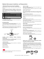
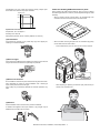
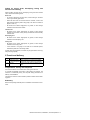
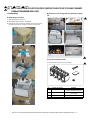
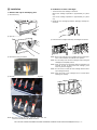
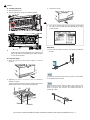
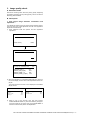
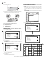
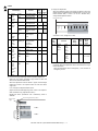
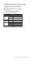
3 ‘14/Jul
INSTALLATION MANUAL
CODE: 00ZMXC250/I3E
DIGITAL FULL COLOR
MULTIFUNCTIONAL SYSTEM
MX-C250/C250E
MX-C250F/C250FE
MX-C250FR
MX-C300F/C300W
MX-C300WE/C300A
MX-C300WR
3
MODEL
3
3
CONTENTS
Transit, Installation (using) environment, Note
[ 1 ] CONFIGURATION . . . . . . . . . . . . . . . . . . . . . . . . . . . . . . . . . . . . 1 - 1
[ 2 ] MX-C250/250E/C250F/C250FE/C250FR/C300F/C300W/C300WE
C300A/C300WR(MAIN UNIT) . . . . . . . . . . . . . . . . . . . . . . . . . . . 2 - 1
[ 3 ] MX-CS11 (500 SHEET Paper Feed Unit) . . . . . . . . . . . . . . . . . . 3 - 1
[ 4 ] Setting, Adjustments, Operation check . . . . . . . . . . . . . . . . . . . . . . . . . . . 4 - 1
[ 5 ] Setup and adjustment data recording . . . . . . . . . . . . . . . . . . . . . 5 - 1
[ 6 ] Necessary works before moving the machine . . . . . . . . . . . . . . . 6 - 1
Parts marked with " " are important for maintaining the safety of the set. Be sure to replace these parts with
specified ones for maintaining the safety and performance of the set.
SHARP CORPORATION
This document has been published to be used
for after sales service only.
The contents are subject to change without notice.
Machine Environment, Installation, and Transportation
Service Manual
1.Machine Environment and Installation
(2)Power voltage
Before installing the machine, check that the following conditions are
satisfied.
Measure the voltage during copying to check that the voltage is in the
range of the specified voltage +/- 10%.
If the installing (use) conditions are not satisfied, the machine may not
exhibit full performance, resulting in problems. It may also cause
safety problems. Using the following information, make sure all
aspects of installation, space, power, transportation, leveling, and
safety are met.
If the voltage is outside the specified range, please have a certified
electrician upgrade the outlet.
No.
1
2
3
4
5
Content
Transportation space
Installing space
Power source (Capacity, fluctuation, safety)
Floor strength
Direct rays of the sun, dust, temperature, humidity, gases,
chemicals
(Electrical work is required.)
Use of a step-up transformer is also available. In this case, the capacity must be great enough for the max. power consumption of the
machine.
(3)Power frequency, waveform
The frequency must be within the range of the specified frequency +/2%. If the power waveform is improper, a problem may occur with the
machine.
(4)Safety
A.Transportation space
Be sure to properly ground the machine.
For installation of a large size machine, be sure to check that the door
size is wide enough before bringing in.
Grounding (earth connection) must be performed before inserting the
power plug into the power outlet.
B.Installing space
When disconnecting the earth connection, be sure to disconnect the
power plug from the power outlet in advance.
The following space must be provided around the machine in order to
assure machine performance and proper operations.
(5)Power plug
If any option is installed, provide the additional space for with installation.
Check the shape of the power plug of the machine, and insert it into a
power outlet of the acceptable shape.
Power plug stated in power capacity.
Adequate space must be provide behind the machine for proper ventilation of heat and dust. The machine will not function properly if heat
and dust cannot be properly expelled from the machine.
D.Floor strength and level
11-13/16"
(30cm)
This machine is considerably heavy and becomes heavier with an
option installed.
The floor must be strong enough to safely support the weight of the
machine as well as any installed options.
If the unit is not properly leveled, toner density may become affected
degrading the copy / print quality.
11-13/16"
(30cm)
C.Power source
safety, plug)
17-23/32"
(45cm)
(Capacity,
voltage,
Also, color shift or image distortion may occur.
To assure proper Image quality, make sure the machine is sitting level.
frequency,
If the power specifications are not satisfied, the machine cannot exhibit
full with performance and may cause safety trouble.
E.Direct rays of the sun, dust, temperature, humidity, gasses, chemicals, vibration
Strictly observe the following specifications.
(1)Power capacity
Check that the following power capacity is satisfied. If not, additionally
provide a proper power source.
Current capacity
Japan: 20A or more
EX 100V: 15A or more
(1)Temperature and humidity (Environmental conditions)
This machine is designed to perform properly under the specified temperature and humidity. If the temperature and humidity exceeds the
specified range, the machine may not operate properly and or cause
equipment failure.
Especially when the humidity is too high, paper absorbs humidity to
cause a paper jam or dirty copy.
EX 200V: 10A or more
Do not install the machine near a heater, an air conditioning outlet, or a
humidifier.
Check the shape of the power plug of the machine, and insert it into a
power outlet of the acceptable shape.
Machine Environment, Installation, and Transportation -i
Condensation may form inside the machine causing multiple problems. Make sure machine has proper ventilation.
F.Note for handling PWB and electronic parts
85%
When handling the PWB and the electronic parts, be sure to observe
the following precautions in order to prevent against damage by static
electricity.
60%
-
When in transit or storing, put the parts in an anti-static bag or an
anti-static case and do not touch them with bare hands.
-
When and after removing the parts from an anti-static bag (case),
use an earth band as shown below:
Humidity㧔RH㧕
20%
Operational environment
Temperature: 10 to 35 degree C
Humidity: 20 to 85% RH
Atmospheric pressure: 590 to 1013hPa (altitude: 0 to 2000 m)
(2)Contaminates
If dust enters the machine, it may cause dirty copy and a paper jam,
resulting in a shortened lifetime.
-
Put an earth band to your arm, and connect it to the machine.
-
When repairing or replacing an electronic part, perform the procedure on an anti-static mat.
(3)Direct sunlight
If the machine is installed in direct sunlight, the exterior of the machine
may be discolored and abnormal copies may be produced.
(4)Gases and chemicals
Do not install the machine at a place where there are gases and chemicals. Especially be careful to avoid installation near a diazo-type
copier, which produces ammonium gas.
Copy quality may be adversely affected and machine problems may
arise.
(5)Vibration
Avoid installation near a machine which produces vibrations.
If vibrations are applied to the copier machine, copy images may be
deflected and a trouble may be caused.
Machine Environment, Installation, and Transportation -ii
G.Note for proper drum, developing, fusing and
transfer unit handling
When handling the OPC drum, developing, fusing units and transfer
units, observe the following items.
Drum unit
-
To prevent damage to the OPC drum, avoid working on the drum
unit in high intensity light areas.
-
When the OPC drum is removed from the machine, cover it with
light blocking material. (When using paper, use about 10 sheets of
paper to cover it.)
-
Be careful not to attach fingerprints, oil, grease, or other foreign
material on the OPC drum surface.
Transfer unit
-
Be careful not to "leave” fingerprints, oil, grease, or other foreign
material on the transfer roller, primary transfer belt and secondary
transfer roller.
Developing unit
-
Be careful not to "leave” fingerprints, oil, grease, or other foreign
material on the developing unit.
Fusing unit
-
Be careful not to "leave” fingerprints, oil, grease, or other foreign
material on the fusing roller.
-
If the machine is not going to be used for an extended period,
release the pressure on the fusing rollers.
If these items are neglected, a trouble may be generated in the copy
and print image quality.
2.Transit and delivery
No.
1
2
Content
Implements, facility, and man power
Delivery
Method
Use a forklift. (If no forklift is available,
manpower of two persons is required.)
Transit must be made in packed condition.
A.Implements, facility, and manpower
It is recommended to use a forklift when moving the machine.
If no forklift is available, man-power of two persons is required. The
machine is considerably heavy, and requires safety precautions for
delivery and installation.
Transit of the machine must be made in packed condition to the installing place.
B.Delivery
Remove the packing materials prior to installation in the office environment.
Machine Environment, Installation, and Transportation -iii
3 ‘14/Jul
Service Manual
MX-C250
[1]
CONFIGURATION
1. System configuration
MX-C250
MX-C250E
MX-C250F/C250FE
2
MX-C250FR
MX-C300E
MX-C300F
MX-C300W/C300WE 2
MX-C300A/C300WR
Digital full color multifunctional system
500 sheet paper feed unit
Sharpdesk 1 license kit
Sharpdesk 5 license kit
Sharpdesk 10 license kit
Sharpdesk 50 license kit
Sharpdesk 100 license kit
2. Product list
A.North America
Product Name
cpm*
MX-C250
25cpm
MX-C300W
30cpm
Panel
Mono
CD
Mono
CD
SAPL
Print
PCL
PS
NW
Scan
Fax
iFAX
STD
No
STD
STD
STD
No
No
STD
No
STD
STD
STD
STD
No
SAPL
Print
PCL
PS
NW
Scan
Fax
iFAX
DF
OSA
HDD
NIC
Wireless
LAN
Copy
No
STD
No
No
STD
STD
DF
STD
SPF
STD
RSPF
OSA
No
No
B.Europe
3
3
Product Name
cpm*
Panel
HDD
NIC
Wireless
LAN
Copy
MX-C250E
25cpm
Mono
CD
No
STD
No
STD
No
STD
STD
STD
No
No
STD
SPF
No
MX-C250F /
MX-C250FE /
MX-C250FR
25cpm
Mono
CD
No
STD
No
STD
No
STD
STD
STD
STD
No
STD
SPF
No
MX-C300E
30cpm
Mono
CD
No
STD
No
STD
No
STD
STD
STD
No
No
STD
RSPF
No
MX-C300W /
MX-C300WE/
MX-C300WR
30cpm
Mono
CD
No
STD
STD
STD
No
STD
STD
STD
STD
No
STD
RSPF
No
Product Name
cpm*
Panel
HDD
NIC
Wireless
LAN
Copy
SAPL
Print
PCL
PS
NW
Scan
Fax
iFAX
DF
OSA
MX-C250
25cpm
No
STD
No
STD
No
STD
STD
STD
No
No
MX-C250F
25cpm
No
STD
No
STD
No
STD
STD
STD
STD
No
MX-C300F
30cpm
No
STD
No
STD
No
STD
STD
STD
STD
No
MX-C300W
30cpm
No
STD
STD
STD
No
STD
STD
STD
STD
No
MX-C300A
30cpm
No
STD
STD
STD
No
STD
STD
STD
No
No
C.Other
3
Mono
CD
Mono
CD
Mono
CD
Mono
CD
Mono
CD
*The same speed in both Color/Monochrome. The same speed in both A4/LTR.
MX-C250 CONFIGURATION 1- 1
STD
SPF
STD
SPF
STD
RSPF
STD
RSPF
STD
RSPF
No
No
No
No
No
3 ‘14/Jul
3. Option list
Model
Feeding equipment
Application
Name
Model name
500-SHEET Paper Feed Unit
Sharpdesk 1 License Kit
Sharpdesk 5 License Kit
Sharpdesk 10 License Kit
Sharpdesk 50 License Kit
Sharpdesk 100 License Kit
STD: Standard provision,
OPT: Option,
MX-CS11
MX-USX1
MX-USX5
MX-US10
MX-US50
MX-USA0
MX-C250, MXC250E, MX-C250F, MX-C250FE, MX-C300E,
MX-C300F, MX-C300W, MX-C300W, MX-C300A
OPT
OPT
OPT
OPT
OPT
OPT
- : No setting
MX-C250 CONFIGURATION 1 - 2
MX-C250FR,
MX-C300WR
OPT
-
3
1
‘13/Oct
2
‘13/Dec
3 ‘14/Jul
Service Manual
[2] MX-C250/C250E/C250F/C250FE/C250FR/C300E/C300F/C300W/C300WE/
C300A/C300WR(MAIN UNIT)
MX-C250
3
1.Unpacking
B.Removal of the fixing tape and protection material
A.Unpacking procedure
1
1) Open the top of the carton box.
2) Remove the parts included in the package.
3) Remove the main unit from the package, and remove the polyethylene bag. Place the machine on a solid, sturdy surface.
* With only for north America model, remove the warning sheet.
1
C.Check the packed items
1) Check that all the parts are in the package.
2
No.
1
Packed part names
Toner cartridge
2
AC cord
3
4
Operation Manual
Ferrite core
Quantity
1 piece for each color
(Other than North America)
200V series only: 1 piece
120V (USA)
1 set
1
MX-C250 MX-C250/C250E/C250F/C250FE/C250FR/C300E/C300F/C300W/C300WE/C300A/C300WR(MAIN UNIT) 2 – 1
[2] Installation
2. Installation of toner cartridges
*
1. Remove the cap of developing unit
1) Remove the tray.
The life of each toner cartridge is as follows:
Black toner cartridge: equivalent to approximately 1K (A4/LT
5%)
Color toner cartridge: equivalent to approximately 1K (A4/LT
5%)
1) Shake the toner cartridge (included in package) vertically several times.
2) Open the front cover.
2) Insert the toner cartridge horizontally and straight until it locks.
3) Remove the silica gel material.
NOTE: Be sure to install the color cartridges to their proper positions. Avoid installation to a different color position.
NOTE: Do not forcibly insert the toner cartridge. Keep holding the
cartridge and completely insert it.
NOTE: When the machine is transported with the developing unit
removed, be sure to remove the toner cartridge. (if not
toner may become clogged.)
NOTE: Do not remove or insert the toner cartridge with the developer cartridge removed.
NOTE: Press the center of the cartridge until it is locked when
installing the cartridge.
4) Remove fixing tapes and the caps on the developing units.
Yellow
Magenta Cyan
Black
NOTE: Be sure to keep the caps. Caps are used when the
machine is transferred to the different location.
MX-C250 MX-C250/MX-C250E/MX-C250F/MX-C250FE/MX-C300E/MX-C300F/C300W/C300WE(MAIN UNIT) 2 – 2
1
‘13/Oct
C. Fusing unit lever
3)
Insert the tray slowly.
4)
Turn ON the machine and press the [SPECIAL FUNCTION]
key on the LCD, and press the [UP] or [DOWN] key to select
"Paper Size Set".
1) Open the right door unit..
2) Turn the levers of the Fusing unit to add the pressure.
1
5. Line cable connection (Only for the machine
with FAX)
NOTE: When the machine is left for one month without using, the
Fusing heat roller could be deformed. If the machine is not
going to be used for an extended period, release the pressure on the fusing rollers.
1) Connect the line cable on the line to the modular jack indicated
as “LINE.”
4. Tray size setup
1) Gently pull out the tray until it stops. If paper is in the tray,
remove it.
It is necessary to prepare the line cable by yourself. The line cable
is not installed into the machine.
2) Adjust the guide plates A and B to the vertical size and the horizontal size of paper.
The guide plates A and B are movable. Hold the fixing knob to
slide the guide plates A and B to match the paper size.
(2)
(1)
When connecting the line cable (to LINE or TEL), wind the line
cable two turns or one turn around the included ferrite core as
shown in the figure, and connect to the modular jack which is
marked with “LINE.”
(2)
(2)
0LATE"
0LATE!
MX-C250 MX-C250/MX-C250E/MX-C250F/MX-C250FE/MX-C300E/MX-C300F/C300W/C300WE(MAIN UNIT) 2 – 3
1
1
‘13/Oct
6. Specifications setting
7. Key sheet replacement (Only for north America)
Use SIM26 to set to the specifications according to the customer's
request.
1) Prepare the following Key sheets depending on the installed
models.
Machine with FAX : HPNLC0082QSZZ KEY SHEET
Machine without FAX : HPNLC0082QSZ1 KEY SHEET 3IN1
SIM No
26 6
Content
Destination setting
2) Remove the protector paper for the Key sheet.
To customize one of the following items after destination setting,
change the set value of the item.
SIM No
26 18
53
Content
Toner save mode enable/disable setting
* For the other destinations, this setting is made by
the user program.
Auto color calibration enable/disable setting
3) Peel off the release paper in 5 to 6 mm from the edge on the
rear side of the Key sheet.
4) Put the Key sheet by attaching the peeled part on the rear side
of the Key sheet to the Operation panel.
At this moment, fit the STOP key, FAX key (only for FAX model)
and COPY key with the Key sheet. (For the machine with FAX)
Or, fit the STOP key, SCANNER key and COPY key with the
Key sheet. (For the machine without FAX)
Note : Do not make the buttons overlapped by the Key sheet
when putting the key sheet. The Key sheet could be banked
by the buttons.
MX-C250 MX-C250/MX-C250E/MX-C250F/MX-C250FE/MX-C300E/MX-C300F/C300W/C300WE(MAIN UNIT) 2 – 4
3. Image quality check
A. Execution items
Execute the checking items about the printing quality. Regarding
the specific procedures for the printing quality, refer to the Service
Manual [5] ADJUSTMENT.
B. Description
1. Print engine image distortion confirmation and
adjustment
This adjustment performs the print engine image distortion adjustment, the OPC drum phase adjustment, and the color registration
adjustment simultaneously.
1)
Enter SIM50-22 mode and perform the auto registration
adjustment.
Sim50-22 AUTO REGIST ADJ
Press OK Key
EXEC
Sim50-22 AUTO REGIST ADJ
EXEC
Sim50-22 AUTO REGIST ADJ㻌 㻌 㻌 㻌 (1/6)
REGIST_SUB_C
00.0
REGIST_SUB_C(DIF)
00.0
REGIST_MAIN_C_F
00.0
REGIST_MAIN_C_F(DIF) 00.0
2) When the adjustment is completed, [EXECUTE] key returns to
the normal display, and the value of the adjustment result is displayed.
The current skew level for each color is displayed on the SKEW
display section.
Sim50-22 AUTO REGIST ADJ㻌 㻌 㻌 㻌 (1/7)
Sim50-22 AUTO REGIST ADJ㻌 㻌 㻌 㻌 (7/7)
SKEW_K
SKEW_C
SKEW_C(DIF)
SKEW_M
REGIST_MAIN_Y_R(DIF)
PHASE
PHASE before
3)
00.0
00.0
00.0
00.0
00.0
00.0
00.0
Make a copy of the servicing color test chart (UKOG0326FCZZ/UKOG-0326FC11), and check that they are proper.
If the test results are not proper, refer to [5] ADJUSTMENT of
the Service Manual and perform the adjustments.
MX-C250 MX-C250/MX-C250E/MX-C250F/MX-C250FE/MX-C300E/MX-C300F/C300W/C300WE(MAIN UNIT) 2 – 5
1
‘13/Oct
MX-C250
[3]
MX-CS11 (500 SHEET PAPER FEED Service
UNIT) Manual
1. Unpacking
2.Installation
A. Removal of the 500 sheet paper feed unit
<Precautions for installation>
Before execution of installation, check to confirm that the data lamp
under it are not lighted or blinking.
A
x2
A.Turn off the power of the main unit
B
x2
1) Check to confirm that the operation panel is turned OFF, and
then turn OFF the power switch.
C
x1
2) Disconnect the power plug from the power outlet.
B.Install the main unit to the MX-CS11.
XEBS740P10000
D
NOTE: If the main unit is combined with the MX-CS11, it must
be used as a desktop machine and must not be used on
the floor in order to prevent against falling.
x3
XHBS740P08000
1) Put the main unit on the MX-CS11 so that they fit together.
NOTE: When holding the main unit, use two persons.
NOTE: When lifting / holding the main engine, never lift / hold
the engine by the scanner unit. Lift the engine at the right and
left cover bottoms using the hand grab indentions provided.
B. Removal of the fixing tape and protection
material
1)
Remove the 500 sheet paper feed unit from the polyethylene
bag, and remove the fixing tape and the protection material.
2) Pull out the trays of the main unit and MX-CS11.
C. Packed items check
1
No.
1
2
3
4
2
3
Name
Plate A
Plate B
Fixing screws (M4 x 10 P Tight)
Fixing screws (M4 x 8 S Tight)
3) Attach the main unit and MX-CS11 with the plates (Packed item
Plate A) and the screws (Packed items M4x10 P Tight and
M4x8 S Tight).
4
Quantity
1
1
1
A
C
3
A
D
MX-C250 MX-CS11 (500 SHEET PAPER FEED UNIT) 3 – 1
1
‘13/Oct
B.Copy image position, image loss, and void area
adjustment (Manual adjustment)
4) Remove the Rear cover. .
1) Place a scale on the document table as shown in the figure
below.
Place a scale so that it is in parallel with the scanning direction
and that its lead edge is in contact with the document guide
plate.
Place white paper on the document table so that the scale lead
edge can be seen.
5) Attach the main unit and MX-CS11 with the plates (Packed item
Plate B) and the screws (Packed items M4x10 P Tight).
B
B
D
D
C.Turn on the power of the main unit
2) Enter the SIM 50-1 mode.
Sim50-01 LEAD EDGE ADJ
1) Power to the main unit.
2) Turn ON the power switch.
1䠖 RRCA
2䠖 RRCB-CS1
3䠖 RRCB-DSK
1 / 6 [ 1/ 99]
3. Adjustments
A.Image off-center automatic adjustment (Document table mode)
㻌㻌
50㻌
50
50
50
1) Enter the SIM50-10 mode.
1
Sim50-10 PAPER OFFSET
1䠖 BK-MAG
2䠖 MAIN-MFT
3䠖 MAIN-CS1
1 / 3 [ 60/ 140]
100㻌
50
50
Sim50-01 LEAD EDGE ADJ
㻌EXEC
㻌
100
1䠖 RRCA
2䠖 RRCB-CS1
3䠖 RRCB-DSK
1 / 6 [ 1/ 99]
2) Set A4 (11" x 8.5") paper in each paper feed tray.
3) Press [START] key.
㻌㻌
51
50
50
51
The adjustment pattern is printed out. (Paper is fed from the
paper feed tray.)
1
3) Set RRCA, LEAD, and SIDE to the default values.
Sim50-10 PAPER OFFSET
Item/Display
1䠖 BK-MAG
2䠖 MAIN-MFT
3䠖 MAIN-CS1
1 / 3 [ 60/ 140]
100㻌
50
50
㻌EXEC
㻌
100
1
2
3
Perform the procedures of 2) - 3) for the printed adjustment pattern of each paper feed tray.
4
Lead
edge
adjustment
value
RRCA
RRCBCS1
RRCBDSK
RRCBMFT
4) Press [OK] key.
The adjustment result becomes valid.
5
RRCBADU
MX-C250 MX-CS11 (500 SHEET PAPER FEED UNIT) 3 – 2
Content
Document lead
edge reference
position (OC)
Regis Standard
-traTray
tion
Desk
motor
ON
Manual
timpaper
ing
feed
adjus ADU
tment
Setting
range
0 - 99
Defau
lt
value
50
1 - 99
40
1 - 99
50
1 - 99
50
1 - 99
50
1
1
‘13/Oct
Setting
range
0 - 99
Defau
lt
value
30
0 - 99
20
Lead edge void
area adjustment
Rear edge void
area adjustment
FRONT/REAR
void area adjustment
OC document offcenter adjustment
1 - 99
40
1 - 99
35
1 - 99
35
1 - 99
DENBMFT
DENBCS1
DENBCS2
SCAN sub scanning magnification ratio
adjustment
(CCD)
Manual feed correction value
Tray 1 correction
value
Tray 2 correction
value
DENBADU
ADU correction
value
1
Item/Display
6
Image
loss
area
setting
value
Void
area
adjustment
7
8
9
10
11
12
13
14
15
16
Content
LEAD
Lead edge image
loss area setting
Side image loss
area adjustment
SIDE
DENA
DENB
FRONT/
REAR
Off-center
adjustment
Magnification
ratio
correction
Sub
scanning
direction print
area
correction
value
Sub
scanning
direction print
area
correction
value
OFFSET_
OC
SCAN_
SPEED_O
C
5) Image loss adjustment
When the adjustment item of the image loss below is set to the
default value, it is adjusted to the standard state. If it is not in the
below standard state, or when it is set to a desired value,
change these adjustment items.
Paper lead edge
Copy area
Maginification ratio : 400%
1
2
3
1 - 99
50
Void area: 4.0mm, Image loss: 4.0mm
50
Item/
Display
LEAD
1 - 99
50
1 - 99
50
1 - 99
50
1 - 99
50
SIDE
Content
Image
loss
adjustment
Lead
edge
image
loss
adjustment
Side
image
loss
adjustment
0 - 99
Default
valu
e
40
Standard
adjustment
value
4.0
+/- 1.0mm
0 - 99
20
2.0
+/- 1.0mm
Adjustment
range
When the adjustment value is increased, the image loss is
increased. When the adjustment value is decreased, the image
loss is decreased.
When the adjustment value is changed by 1, the void area is
changed by 0.1mm.
Shift to the copy mode, and make a copy at each of 100% and
200% in the document table mode.
When the adjustment value of RRCA is proper, the lead edge
image from 4.0mm is not copied in either of 100% and 200%
copy scale.
If not, change and adjust the RRCA value.
(Adjust so that the lead edge image from 4.0mm is not copied in
either of different copy magnification ratios.)
Repeat the above procedures until a satisfactory result is
obtained.
Scale image 4.0mm position
Paper lead
edge
100%
200%
5mm
10mm
5mm
4) Perform the image lead edge reference position adjustment.
5mm
4
10mm
MX-C250 MX-CS11 (500 SHEET PAPER FEED UNIT) 3 – 3
Service Manual
[4] Setting, Adjustments, Operation check
MX-C250
1.
Firmware version check and version
up
After installation of all the options to the machine, use SIM49-1 to
check the version of each firmware. If it is not the latest version,
upgrade it to the latest one.
2.
Function and operation check
Check that the following operations are normal.
Check item list
Key-in (operation panel)
Display (operation panel)
Paper feed
Hand feed
operation
Main unit paper
tray
Desk unit paper
feed tray
Paper size detection
Originals size
Original table
detection
mode
RSPF mode
RSPF operation / S-S mode
two sided copy
D-S mode
S-D mode
D-D mode
Paper exit operation
Equipped condition
With the desk unit installed
MX-C250 Setting, Adjustments, Operation check 4 – 1
Service Manual
[5] Setup and adjustment data recording
MX-C250
Print the various setup data and the adjustment data (list) with
SIM22-6 and keep the data.
- In case of a memory trouble, if the data is not kept, all the adjustments must be made again.
- If the data is kept, the setup values and the adjustment values
can be entered without adjustments, shortening the servicing
time.
MX-C250 Setup and adjustment data recording 5 – 1
MX-C250
Manual
[6]
Necessary works before moving theService
machine
1)
If the following options are installed, remove all of them from
the machine.
2)
Remove the following consumable parts from the machine.
- Paper pass unit
- Paper
- Toner cartridges
- Development cartridge
3)
Lock the following sections.
- Scanner (Optical section)
- Paper cassette lift plate
Since the hard disk drive is built in the machine, use care not to
exert vibrations or shocks to the machine when in transit.
MX-C250 Necessary works before moving the machine 6 – 1
LEAD-FREE SOLDER
The PWB’s of this model employs lead-free solder. The “LF” marks indicated on the PWB’s and the Service Manual mean “Lead-Free” solder.
The alphabet following the LF mark shows the kind of lead-free solder.
Example:
<Solder composition code of lead-free solder>
Lead-Free
5mm
Solder composition
code (Refer to the
table at the right.)
a
Solder composition
Solder composition code
Sn-Ag-Cu
a
Sn-Ag-Bi
Sn-Ag-Bi-Cu
b
Sn-Zn-Bi
z
Sn-In-Ag-Bi
i
Sn-Cu-Ni
n
Sn-Ag-Sb
s
Bi-Sn-Ag-P
Bi-Sn-Ag
p
(1) NOTE FOR THE USE OF LEAD-FREE SOLDER THREAD
When repairing a lead-free solder PWB, use lead-free solder thread.
Never use conventional lead solder thread, which may cause a breakdown or an accident.
Since the melting-point of lead-free solder thread is about 40°C higher than that of conventional lead solder thread, the use of the
exclusive-use soldering iron is recommended.
(2) NOTE FOR SOLDERING WORK
©
Since the melting-point of lead-freeCOPYRIGHT
solder is about 220°C, which
is about
40°C higher
than that of conventional lead solder, and its soldering
XXXX
BYSHARP
CORPORATION
capacity is inferior to conventional one, it is apt to keep the soldering iron in contact with the PWB for longer time. This may cause land
separation or may exceed the heat-resistive temperature
components.
Use enough care to separate the soldering iron from the PWB when
ALLofRIGHTS
RESERVED.
completion of soldering is confirmed.
Since lead-free solder includes a greater quantity of tin, the iron tip may corrode easily. Turn ON/OFF the soldering iron power frequently.
If different-kind solder remains on the soldering iron tip, it is melted together with lead-free solder. To avoid this, clean the soldering iron
No part of this publication may be reproduced,
tip after completion of soldering work.
stored in a retrieval system, or transmitted in
If the soldering iron tip is discolored black during soldering work, clean and file the tip with steel wool or a fine filer.
any form or by any means, electronic, mechanical,
photocopying, recording, or otherwise, without
prior written permission of the publisher.
CAUTION FOR BATTERY REPLACEMENT
(Danish)
ADVARSEL !
Lithiumbatteri – Eksplosionsfare ved fejlagtig håndtering.
Udskiftning må kun ske med batteri
af samme fabrikat og type.
Levér det brugte batteri tilbage til leverandoren.
(English)
Caution !
Danger of explosion if battery is incorrectly replaced.
Replace only with the same or equivalent type
recommended by the manufacturer.
Dispose of used batteries according to manufacturer’s instructions.
(Finnish)
VAROITUS
Paristo voi räjähtää, jos se on virheellisesti asennettu.
Vaihda paristo ainoastaan laitevalmistajan suosittelemaan
tyyppiin. Hävitä käytetty paristo valmistajan ohjeiden
mukaisesti.
(French)
ATTENTION
Il y a danger d’explosion s’ il y a remplacement incorrect
de la batterie. Remplacer uniquement avec une batterie du
même type ou d’un type équivalent recommandé par
le constructeur.
Mettre au rebut les batteries usagées conformément aux
instructions du fabricant.
(Swedish)
VARNING
Explosionsfara vid felaktigt batteribyte.
Använd samma batterityp eller en ekvivalent
typ som rekommenderas av apparattillverkaren.
Kassera använt batteri enligt fabrikantens
instruktion.
(German)
Achtung
Explosionsgefahr bei Verwendung inkorrekter Batterien.
Als Ersatzbatterien dürfen nur Batterien vom gleichen Typ oder
vom Hersteller empfohlene Batterien verwendet werden.
Entsorgung der gebrauchten Batterien nur nach den vom
Hersteller angegebenen Anweisungen.
CAUTION FOR BATTERY DISPOSAL
(For USA, CANADA)
“BATTERY DISPOSAL”
THIS PRODUCT CONTAINS A LITHIUM PRIMARY
(MANGANESS DIOXIDE) MEMORY BACK-UP BATTERY
THAT MUST BE DISPOSED OF PROPERLY. REMOVE THE
BATTERY FROM THE PRODUCT AND CONTACT YOUR
LOCAL ENVIRONMENTAL AGENCIES FOR INFORMATION
ON RECYCLING AND DISPOSAL OPTIONS.
“TRAITEMENT DES PILES USAGÉES”
CE PRODUIT CONTIENT UNE PILE DE SAUVEGARDE DE
MÉMOIRE LITHIUM PRIMAIRE (DIOXYDE DE MANGANÈSE)
QUI DOIT ÊTRE TRAITÉE CORRECTEMENT. ENLEVEZ LA
PILE DU PRODUIT ET PRENEZ CONTACT AVEC VOTRE
AGENCE ENVIRONNEMENTALE LOCALE POUR DES
INFORMATIONS SUR LES MÉTHODES DE RECYCLAGE ET
DE TRAITEMENT.
#/092)'(4 © "9 3(!20 #/20/2!4)/.
!LL RIGHTS RESERVED
0RODUCED IN *APAN FOR ELECTRONIC $ISTRIBUTION
.O PART OF THIS PUBLICATION MAY BE REPRODUCED
STORED IN A RETRIEVAL SYSTEM OR TRANSMITTED
IN ANY FORM OR BY ANY MEANS
ELECTRONIC MECHANICAL PHOTOCOPYING RECORDING OR OTHERWISE
WITHOUT PRIOR WRITTEN PERMISSION OF THE PUBLISHER
4RADEMARK ACKNOWLEDGEMENTS
v -ICROSOFT¤ 7INDOWS¤ 7INDOWS¤ 7INDOWS¤ -E 7INDOWS .4¤ 7INDOWS¤ 7INDOWS¤ 80 7INDOWS¤ 6ISTA 7INDOWS¤ 7INDOWS ¤ ¤
7INDOWS¤ 3ERVER 7INDOWS¤ 3ERVER 7INDOWS3ERVER
¤
AND )NTERNET %XPLORERARE
REGISTERED TRADEMARKS OR TRADEMARKS OF
-ICROSOFT #ORPORATION IN THE 53!AND OTHER COUNTRIES
v 0OST3CRIPT IS A REGISTERED TRADEMARK OF !DOBE 3YSTEMS )NCORPORATED
v -ACINTOSH -AC /3 !PPLE4ALK %THER4ALK ,ASER 7RITER AND 3AFARI ARE REGISTERED
TRADEMARKS OR TRADEMARKS OF !PPLE #OMPUTER )NC
v )"- 0#!4 AND 0OWER 0# ARE TRADEMARKS OF )NTERNATIONAL "USINESS -ACHINES
#ORPORATION
v !CROBAT¤ 2EADER #OPYRIGHT¤ !DOBE 3YSTEMS )NCORPORATED !LL RIGHTS
RESERVED !DOBE THE !DOBE LOGO !CROBAT AND THE !CROBAT LOGO ARE TRADEMARKS OF
!DOBE 3YSTEMS )NCORPORATED
v 0#, IS A REGISTERED TRADEMARK OF THE (EWLETT0ACKARD #OMPANY
v 3HARPDESK IS A TRADEMARK OF 3HARP #ORPORATION
v !LL OTHER TRADEMARKS AND COPYRIGHTS ARE THE PROPERTY OF THEIR RESPECTIVE OWNERS
SHARP CORPORATION
Business Solutions CS Promotion Center II
Yamatokoriyama, Nara 639-1186, Japan
First Edition 2013 September
Latest Edition 2014 July