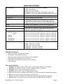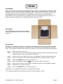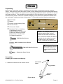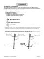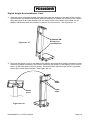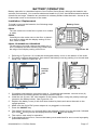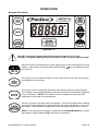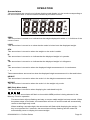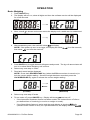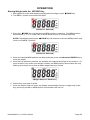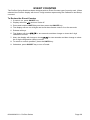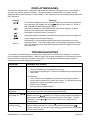
1
ProDoc Series
Digital Physician Scale
PD100
PD200
PD300
PD300DHR
(Digital Height Rod)
and
PD300MHR
(Mechanical Height Rod)
Owner’s Manual
0044-M340-O1 Rev A
05/08
QuickMedical - Authorized Distributor
PO Box 1052 y Snoqualmie, WA 98065
Ph:888-345-4858 y Fax: 421-831-6032
www.quickmedical.com/detecto/
Technical
Support:
0044-M340-O1
y ProDoc
Series Ph: 866-254-8261 y [email protected]
Page 1
0044-M340-O1 y ProDoc Series
Page 2
TABLE OF CONTENTS
SPECIFICATIONS ……………………………………………………………………………….
Standard Features …..…………………………………………………………………….…
Care and Cleaning …..…………………………………………………………………….…
PD100 ……………………………………………………………………………………………..
Unpacking …………………………………………………………………………………….
Assembly ……………………………………………………………………………………...
Quick Start …………………………………………………………………………………….
Placing the Scale …………………………………………………………………………..…
Placing the Display ….……………………………………………………………………..…
Wall Mounting …………………………………………………………………………….
Desk or Table Mounting ………………………………………………………………….
PD200 ……………………………………………………………………………………………..
Unpacking …………………………………………………………………………………….
Assembly ……………………………………………………………………………………...
Quick Start …………………………………………………………………………………….
PD300 ……………………………………………………………………………………………..
Unpacking ....………………………………………………………………………………….
Assembly ..………………………….………….…………………………………………......
Quick Start ………………………………………………………………………………….…
PD300DHR ..……………………………………………………………………………………...
Digital Height Rod Installation ………………………………………………………………
PD300MHR ...……………………………………………………………………………………..
Mechanical Height Rod Installation …………………………………………………………
BATTERY OPERATION ...…………...…………….……………………………………………
Installation/Replacement .………………….……………………………………………..…
Low Battery ……………………………………………………………………………………
Automatic Shutoff ……………………………………………………………………….……
Sleep Mode ……………………………………………………………………………………
OPTIONAL AC POWER ADAPTOR .……….…………………………………………………
OPERATION …………………………………….……………………………………………..…
Keypad Functions ………………………….…………………………………………………
Annunciators ……………………………….…………………………………………………
Basic Weighing .………………………………………………………………………………
Weighing with Height and BMI Measure ……………………………………………………
With Digital Height Rod ………….………………………………………………………
With Mechanical Height Rod or No Height Rod ………………………………………
Storing Weight with the zSTORE Key ……………..………………………………………
Recalling Weight with the yRECALL Key …………………………………………………
SETUP ……………….……………………………………………………………………………
CALIBRATION ..……….…………………………………………………………………………
EVENT COUNTER ………………………………………………………………………………
DISPLAY MESSAGES …..………………………………………………………………………
TROUBLESHOOTING …..………………………………………………………………………
0044-M340-O1 y ProDoc Series
1
1
1
3
3
3
3
4
4
4
6
7
7
7
7
8
8
8
12
13
13
15
15
17
17
18
18
18
18
19
19
21
22
23
23
24
25
26
27
28
30
31
31
Page 3
INTRODUCTION
Thank you for purchasing our Detecto ProDoc Series Digital Physician Scale. Your scale has
been designed for simple and straightforward use and to assure accuracy and dependability for
years to come.
Please read this manual thoroughly before attempting to use your scale and keep it handy for
future reference. It contains important instructions for installation and proper operation of your
scale.
FCC Compliance Statement
WARNING! This equipment generates uses and can radiate radio frequency and if not installed
and used in accordance with the instruction manual, may cause interference to radio
communications. It has been tested and found to comply with the limits for a Class A computing
device pursuant to Subpart J of Part 15 of FCC rules, which are designed to provide reasonable
protection against such interference when operated in a commercial environment. Operation of
this equipment in a residential area may cause interference in which case the user will be
responsible to take whatever measures necessary to correct the interference.
You may find the booklet "How to Identify and Resolve Radio TV Interference Problems"
prepared by the Federal Communications Commission helpful. It is available from the U.S.
Government Printing Office, Washington, D.C. 20402. Request stock No. 001-000-00315-4.
All rights reserved. Reproduction or use, without expressed written permission, of editorial or
pictorial content, in any manner, is prohibited. No patent liability is assumed with respect to the
use of the information contained herein. While every precaution has been taken in the
preparation of this manual, the Seller assumes no responsibility for errors or omissions. Neither
is any liability assumed for damages resulting from use of the information contained herein. All
instructions and diagrams have been checked for accuracy and ease of application; however,
success and safety in working with tools depend to a great extent upon the individual’s accuracy,
skill and caution. For this reason the Seller is not able to guarantee the result of any procedure
contained herein. Nor can they assume responsibility for any damage to property or injury to
persons occasioned from the procedures. Persons engaging the procedures do so entirely at
their own risk.
Serial Number_______________________
PRECAUTIONS
Date of Purchase ____________________
Before using this scale, read this manual
and pay special attention to all "WARNING"
symbols:
Purchased From_____________________
___________________________________
___________________________________
___________________________________
RETAIN THIS INFORMATION FOR FUTURE USE
0044-M340-O1 y ProDoc Series
IMPORTANT
ELECTRICAL
WARNING
Page 4
SPECIFICATIONS
Model Number …………………
PD100 (Floor Scale with Remote Display)
PD200 (Floor Scale
PD300 (Eye-Level Scale)
PD300DHR (Eye-Level Scale with Digital Height Rod)
PD300MHR (Eye-Level Scale with Mechanical Height Rod)
Capacity ...……………………….. 480 lb x 0.2 lb (220 kg x 0.1 kg)
Weight Units ......………………… Pounds or Kilograms (selectable)
Power Requirements …………… Six (6) “AA” size Alkaline batteries (not included) OR an
optional Medical device 9V AC/DC wall plug-in adapter
(Cardinal part number PD-AC, includes USA plug). Also
available UK plug (PD-UKPLUG) or EU plug (PD-EUPLUG).
Display …………………………… Five digit, seven segment, 1.0 inch (25 mm) high LCD
Operation Temperature ………… 50 to 104 ºF (+10 to +40 ºC)
Function Keys …………………… ZERO, UNITS, LOCK/RELEASE, BMI HEIGHT/ENTER,
yRECALL, zSTORE and ON/OFF
Dimensions
PD100 Display ..……..........
Base ……………....
PD200 ……………………….
PD300 ……………………….
PD300MHR …………………
PD300DHR ………...............
5.25” H x 7.75” W x 2.125” D (134 mm x 197 mm x 54 mm)
3.33” H x 12.5” W x 13.0” D (85 mm x 318 mm x 330 mm)
8.75” H x 12.5” W x 16.5” D (222 mm x 318 mm x 419 mm)
48.0” H x 12.5” W x 16.5” D (86 mm x 318 mm x 419 mm)
48.0” H x 14.5” W x 16.5” D (86 mm x 368 mm x 419 mm)
48.0” H x 14.5” W x 16.5” D (86 mm x 368 mm x 419 mm)
Shipping Weight …..……………. PD100 = 21.20 lb (9.60 kg)
PD200 = 24.90 lb (11.30 kg)
PD300 = 35.70 lb (16.20 kg)
PD300DHR = 42.30 lb (19.20 kg)
PD300MHR = 42.30 lb (19.20 kg)
Standard Features:
y
y
y
y
y
y
Metric Conversion (Weight and Height)
Body Mass Index (BMI) Calculator
Memory Function (Store and Recall up to four weights)
Selectable Sleep-Mode (up to 9 minutes)
Selectable Auto Shut-Off Feature (up to 9 minutes)
Level Indicator
Care and Cleaning
1.
2.
3.
4.
5.
6.
7.
8.
DO NOT submerge scale in water, pour or spray water directly on the display.
DO NOT use acetone, thinner or other volatile solvents for cleaning.
DO NOT expose scale to temperature extremes.
DO NOT place scale in front of heating/cooling vents.
DO clean the scale and display with a damp soft cloth and mild non-abrasive detergent.
DO remove power before cleaning with a damp cloth.
DO provide clean AC power and adequate protection against lightning damage.
DO keep the surroundings clear to provide clean and adequate air circulation.
0044-M340-O1 y ProDoc Series
Page 1
This page intentionally left blank.
0044-M340-O1 y ProDoc Series
Page 2
PD100
Unpacking
Remove the scale base, display, hardware pack and other components from the shipping
carton. After removing from the carton, check for any damage that may have taken place during
shipment. Keep and use the original carton and packing material for return shipment if it should
become necessary. The purchaser is responsible for filing all claims for any damages or loss
incurred during transit. Remove all plastic wrapping, foam fillers and cardboard material from
the scale base, display and other components. You should have the following components:
(1) Scale Base
(1) Remote Display
(1) Wall Bracket “A”
(includes four (4) feet for desk or table mounting)
(1) Wall Bracket “B”
(1) Hardware Pack, containing:
(2) M3.0x25 Screws and plastic wall anchors
M3.0x25 Screw
Plastic Wall Anchor
Assembly
The PD100 does not require any assembly. After installing batteries, the scale is ready for
operation.
Quick Start
Although it is recommended that you read this manual before attempting to operate the scale,
this section is included to provide a condensed set of instructions on installing and using the
scale. At a minimum, please make certain you read all of the caution and warning statements.
Step 1.
Place the scale on the floor and then place the display at a convenient distance
from the scale base.
Step 2.
Turn the scale over on the floor and then locate the battery access cover on the
bottom of the scale.
Step 3.
Remove the cover, install six (6) “AA” size batteries1 and then replace the cover.
Step 4.
Turn the scale over to the normal operating position and make sure it is level.
Step 5.
Press the ON/OFF key to turn the scale on.2
Step 6.
When the display is showing 0.0, have to patient step on the scale.
Step 7.
Wait a few seconds for the weight to display and then read the patient’s weight.
Step 8.
Patient may now step off scale.
Step 9.
Press the ON/OFF key to turn the scale off.
1
See page 17 for detailed instructions on installing the batteries.
2
For complete Operation and Setup instructions, refer to pages 19 to 27.
0044-M340-O1 y ProDoc Series
Page 3
PD100
Placing the Scale
The scale should be placed on a flat, level floor or low cut carpet away from any rapidly moving
air source (heating and cooling vents).
Check to make certain the scale is level. The level indicator is
located at the rear of the scale. If the scale is not level (the bubble
will not be centered), loosen the locking ring on all four (4) feet and
adjust them as required to center the bubble and attain a level
scale. Once the scale is level, lock the feet in place by tightening
NOT LEVEL
the adjustment locking rings against the bottom of the scale.
LEVEL
IMPORTANT! Any time a scale is moved or re-located, be sure to check the level
bubble to make sure the scale is level before using.
Placing the Display
The PD100 display has a 87” (220 cm) cable to allow it to be placed at a convenient position
away from the scale base. A bracket is included to mount the display on a wall or the bracket
(and included feet) can used to place it on a desk for easy viewing.
Wall Mounting
1. Choose the location to mount the display on the wall. The location should be free of
temperature extremes and water. It should be where the display can be easily viewed,
not subject to direct sunlight and where the keypad is within easy reach of the operator.
2. Make certain the structure and mounting hardware are of sufficient strength to support the
display. The mounting bracket should be securely fastened to the wall so that it cannot
break loose from the mounting surface.
3. Referring to Figure No. 1 and using Wall Bracket “B” for a template, place the bracket
against the wall (the notch (arrow) pointing up) and mark the holes to use to mount it.
Remove the bracket and drill two (2) 13/64” (5 mm) holes in the wall for the mounting wall
anchors.
4. Insert the wall anchors in the wall until they are flush with the wall.
5. With the notch (arrow) pointing up on Wall Bracket “B”, insert the two (2) M3.0x25 screws
through the bracket and into the wall anchors.
6. Tighten the screws to secure the bracket to the wall.
Figure No. 1
13/64” (5 mm)
Hole in Wall
Plastic Wall Anchor
Wall Bracket “B”
M3.0x25 Screw
0044-M340-O1 y ProDoc Series
Page 4
PD100
Placing the Display
Wall Mounting, Cont.
7. Referring to Figure No. 2, make sure the four (4) feet of Wall Bracket “A” are placed in the
bracket.
Display
Feet
(for Desk or
Table Mounting)
Wall
Bracket
“A”
Figure No. 2
Figure No. 3
8. Next, locate the four (4) slots on the back of the display and align them with the four (4)
tabs on the Wall Bracket “A”. Refer to Figure No. 3.
9. Insert the tabs into the slots and press together until the bracket locks to the back of the
display.
10. Referring to Figure No. 4, align the cutout in Wall Bracket “A” with Wall Bracket “B” and
gently pull down to secure the display to the wall.
Wall
Bracket
“A”
Figure No. 4
Display
0044-M340-O1 y ProDoc Series
Wall
Bracket
“B”
Page 5
PD100
Placing the Display
Desk or Table Mounting
1. The location chosen should be a stable, level surface (either a desk or solid table), free of
temperature extremes and water. The display should be where it can be easily viewed,
not subject to direct sunlight and where the keypad is within easy reach of the operator.
2. Referring to Figure No. 5, remove the four (4) feet from inside Wall Bracket “A” and install
them in each corner of the bracket as shown in Figure No. 6.
Remove Feet from
Wall Bracket “A”
Install Feet in
Wall Bracket “A”
Figure No. 5
Figure No. 6
3. Next, locate the four (4) slots in the back of the display. Refer to Figure No. 7.
Figure No. 7
Figure No. 8
Display
Wall
Bracket “A”
with Feet
Installed
Slot
Tab
4. Referring to Figure No. 8, align and insert the tabs on the bracket with the slots in the
display back and press together until the bracket locks to the back of the display.
0044-M340-O1 y ProDoc Series
Page 6
PD200
Unpacking
Remove the scale from the carton by grasping the column (not the display) and lifting up with
equal force on the column and the scale base. After removing from the carton, check for any
damage that may have taken place during shipment. Keep and use the original carton and
packing material for return shipment if it should become necessary. The purchaser is
responsible for filing all claims for any damages or loss incurred during transit. Remove all
plastic wrapping, foam fillers and cardboard material from the scale.
Assembly
The PD200 does not require any assembly.
After installing batteries, the scale is ready for
operation.
Quick Start
Although it is recommended that you read this manual before attempting to operate the scale,
this section is included to provide a condensed set of instructions on installing and using the
scale. At a minimum, please make certain you read all of the caution and warning statements.
Step 1.
Place the scale on the floor.
Step 2.
Carefully turn the scale over with the display resting on the floor and then locate the
battery access cover on the bottom of the scale.
Step 3.
Remove the cover, install six (6) “AA” size batteries1 and then replace the cover.
Step 4.
Turn the scale over to the normal operating position and make sure it is level.
Step 5.
Press the ON/OFF key to turn the scale on.2
Step 6.
When the display is showing 0.0, have to patient step on the scale.
Step 7.
Wait a few seconds for the weight to display and then read the patient’s weight.
Step 8.
Patient may now step off scale.
Step 9.
Press the ON/OFF key to turn the scale off.
1
See page 17 for detailed instructions on installing the batteries.
2
For complete Operation and Setup instructions, refer to pages 19 to 27.
0044-M340-O1 y ProDoc Series
Page 7
PD300
Unpacking
Remove the scale base, display, hardware pack and other components from the shipping
carton. After removing from the carton, check for any damage that may have taken place during
shipment. Keep and use the original carton and packing material for return shipment if it should
become necessary. The purchaser is responsible for filing all claims for any damages or loss
incurred during transit. Remove all plastic wrapping, foam fillers and cardboard material from
the scale base, display and other components. You should have the following components:
c Scale Base
d Display
e Column (under packing filler)
f Column Cover
g Connection Cable
h Hardware Pack, containing:
c
d
f g
h
½
e
(1) M4 Machine Screw
(1) M2.3 Column Cover Screw
(2) M4.5x25 Machine Screws
(3) Connector Case Screws
(1) Philips Screwdriver
NOTE! The Column (Iteme), is
under a packing filler and not
visible until the filler is removed.
Also, note that if a DHR or MHR is
ordered with the scale, its carton
will be on top of the Column’s
carton, replacing the packing filler.
M4 Machine Screw
M2.3 Column Cover Screw
M4.5x25 Machine Screw
½ If purchased, the
optional Medical device
9V AC/DC wall plug-in
adapter will be packed
here.
Connector Case Screw
Assembly
Installing the Column and Display
1. Insert the column into the column cover.
Connector
Case
Column
Column
Cover
Figure No. 9
0044-M340-O1 y ProDoc Series
Page 8
PD300
Assembly
Installing the Column and Display, Cont.
2. Insert the socket end of the connection
cable into the column connector case.
Feed cable through entire length of column.
Refer to Figure No. 10 to insure correct
connector on each end of column.
Column
Connector
Case
Connection
Cable
Figure No. 10
3. Place the scale on a desk or table
Connection
Cable
4. Connect the socket end of the connection cable to
the preset cable in the scale base.
Preset
Cable
Figure No. 11
5. Align the long slot in the column with the slot in the column holder and then insert the column
into the hole on the column holder.
NOTE! Make sure the preset cable passes through the slots in both the column (the long slot)
and the column holder.
Figure No. 12
Slot in
Column
Preset
Cable
0044-M340-O1 y ProDoc Series
Column
Slot in
Column
Holder
Preset
Cable
Page 9
PD300
Assembly
Installing the Column and Display, Cont.
6. Insert the M4 machine screw through the column
holder into the column and tighten the screw to
attach the column to the column holder.
Column
Holder
Column
M4 Machine Screw
Figure No.13
7. Slide the column cover down the column and into
the column holder.
Column
Cover
7.1. Locate the two (2) tabs on the front of the
column cover and the two (2) slots in the
column holder.
Column
Holder
7.2. Align the tabs with the slots and press
together until the tabs on column cover
snaps into slots of the column holder.
Figure No. 14
Column
Cover
8. Lay the scale down with the column
horizontal to the desk or table.
Column
M2.3
Screw
8.1. Attach back of column cover to the
column holder using the M2.3 screw.
8.2. Insert the two (2) M4.5x25 machine
screws through the holes in the
column holder into the column and
tighten the screws to secure the
column to the column holder.
Figure No. 15
0044-M340-O1 y ProDoc Series
Column
Holder
M4.5x25 Machine Screws
Page 10
PD300
Assembly
Installing the Column and Display, Cont.
Display
9. Remove the scale from the desk
or table and place it upright on
the floor.
Preset
Cable
10. Connect the plug end of the
connection cable to the preset
cable from the display and then
insert the cable into the column.
Tab
Connection
Cable
11. Locate the two (2) tabs (one on each side)
on the connector case and the two (2) slots
in the bottom of the display.
11.1. Align the tabs with the slots and
press together until the tabs on the
connector case snap into the slots in
the bottom of the display.
Figure No. 16
Slots
Tab
Tab
Connector
Case
Display
Bottom
Figure No. 17
12. Secure the display to the connector case with the
supplied three (3) screws.
Connector
Case
Screws
Figure No. 18
0044-M340-O1 y ProDoc Series
Page 11
PD300
Quick Start
Step 1.
Once the scale is assembled, place it on the floor.
Step 2.
Carefully lay the scale over on its side with the edge of the display resting on the
floor and then locate the battery access cover on the bottom of the scale.
Step 3.
Remove the cover, install six (6) “AA” size batteries1 and then replace the cover.
Step 4.
Return the scale to the upright, normal operating position and make sure it is level.
Step 5.
Press the ON/OFF key to turn the scale on.2
Step 6.
When the display is showing 0.0, have to patient step on the scale.
Step 7.
Wait a few seconds for the weight to display and then read the patient’s weight.
Step 8.
Patient may now step off scale.
Step 9.
Press the ON/OFF key to turn the scale off.
1
See page 17 for detailed instructions on installing the batteries.
2
For complete Operation and Setup instructions, refer to pages 19 to 27.
0044-M340-O1 y ProDoc Series
Page 12
PD300DHR
Digital Height Rod Installation
The Digital Height Rod is packed in its own carton inside the main carton. Before starting
installation, please unpack carefully and remove all plastic wrappings, foam fillers and cardboard
material. You should have the following components:
(1) Detecto Digital Height Rod (DHR)
(1) Upper Mounting Bracket (with 2 plastic cable clips)
(1) Lower Mounting Bracket
(1) Hardware Pack, containing:
(8) M4x4.5 PM Screws (bracket to height rod)
(4) M4x8.0 PM Screws (bracket to column)
(4) Lock Washers (bracket to column)
M4x4.5 Machine Screw
M4x8.0 Machine Screw
Lock Washer
1. Referring to Figure No. 19, align the upper bracket with the holes in the height rod (near the
headpiece) and install four (4) M4x4.5 PM screws to secure the bracket to the height rod.
2. Next, align the lower bracket with the lower holes in the height rod and install four (4) M4x4.5
PM screws to secure the bracket to the height rod. See Figure No. 20.
M4x4.5 PM
Screws (4)
Figure No. 19
0044-M340-O1 y ProDoc Series
Upper Bracket
(with Cable Clips)
M4x4.5 PM
Screws (4)
Figure No. 20
Lower Bracket
(no Cable Clips)
Page 13
PD300DHR
Digital Height Rod Installation, Cont.
3. Align the upper mounting bracket with the holes near the display in the back of the column
and install two (2) M4x8.0 PM screws with lock washers to secure the bracket to the column.
Align the holes in the lower bracket with the lower holes in the column and install two (2)
M4x8.0 PM screws with lock washers to secure it to the column. See Figure No. 21.
Figure No. 21
(4) M4x8.0 PM
Screws and
Lock Washers
4. Remove the plastic cover on the back of the display exposing the modular connector socket.
Insert the modular connector of the DHR cable into the socket on the display until it locks in
place. (It will click when locked in place). Route the DHR cable through the two (2) plastic
cable clips on the upper bracket. See Figure No. 22
DHR
Cable
Plastic
Cover
Cable
Clips
Figure No. 22
0044-M340-O1 y ProDoc Series
Page 14
PD300MHR
Mechanical Height Rod Installation
The Mechanical Height Rod is packed in its own carton inside the main carton. Before starting
installation, please unpack carefully and remove all plastic wrappings, foam fillers and cardboard
material. You should have the following components:
(1) Detecto Mechanical Height Rod (MHR)
(2) Mounting Brackets
(1) Hardware Pack, containing:
(4) #8-32x1/2” Pan Head Screws (mounting bar to bracket)
(4) #8-32 Hex Nuts
(4) M4x8.0 PM Screws (bracket to column)
(4) Lock Washers (bracket to column)
(2) #8-32 Hex Head Screw (MHR to mounting bar)
(1) Wrench
#8-32 Pan Head Screw
#8-32 Hex Head Screw
#8-32 Hex Nut
M4x8.0 Machine Screw
Wrench
Lock Washer
1. Referring to Figure No. 23, align a
bracket with the holes near the top
of the mounting bar and install two
(2) #8-32x1/2” Pan Head screws
and #8-32 Hex nuts to secure the
bracket to the mounting bar.
#8-32 Pan
Head Screw
#8-32
Hex Nut
Mounting
Bracket
2. Next, align the other bracket with the
lower holes in the mounting bar and
install two (2) #8-32x1/2” Pan Head
screws and #8-32 Hex nuts to
secure the bracket to the mounting
bar.
3. Install the two (2) #8-32 Hex Head
screws in the threaded holes in the
mounting bar and tighten them with
the included wrench until the hex
heads are 1/8" from the bar
#8-32 Hex
Head Screw
Mounting
Bar
#8-32 Pan
Head Screw
Mounting
Bracket
#8-32
Hex Nut
#8-32 Hex
Head Screw
Figure No. 23
0044-M340-O1 y ProDoc Series
Page 15
PD300MHR
Mechanical Height Rod Installation, Cont.
4. Align the upper mounting bracket with the holes near the display in the back of the column
and install two (2) M4x8.0 PM screws to secure the bracket to the column.
5. Align the holes in the lower bracket with the lower holes in the column and install two (2)
M4x8.0 PM screws with lock washers to secure it to the column. See Figure No. 24.
(4) M4x8.0 PM
Screws and
Lock Washers
Figure No. 24
Figure No. 25
6. Referring to Figure No. 25, place both height rod brackets over the two (2) hex head screws
and pull down, securing brackets. Use included wrench to tighten hex head screws.
Operation
1. Before patient steps on scale, headpiece should be
rotated to horizontal position, and raised well above
patient's head.
2. Patient may now step on scale.
3. Carefully lower height rod while keeping headpiece
E
horizontal, until it rests on top of patient's head. If
patient is shorter than 3' 4" (101.5 cm), push latch to
right while simultaneously pushing down on headpiece,
until headpiece rests on top of patient's head.
4. Read height of patient as follows:
If back of headpiece points to outer height rod, then it
points to correct height.
If back of headpiece points to inner height rod, then
correct height is read at top of outer height rod (see
"Read" arrow on outer height rod).
A
B
C
D
Height Rod in
“rest” Position
A = Latch
B = Headpiece
C = Inner Height Rod
D = Outer Height Rod
E = Measurement
“Read” Line
5. While holding headpiece horizontally, raise it above patient’s head. Patient may now step off scale.
6. Rotate headpiece back to vertical position and adjust height rod to “rest” position (headpiece should
be locked in place within inner height rod and inner rod should be at its lowest position).
0044-M340-O1 y ProDoc Series
Page 16
BATTERY OPERATION
Battery operation is a standard feature of the ProDoc Series Scale, although the batteries are
optional (not included). You must first obtain and install six (6) "AA" size Alkaline batteries before
operations can begin. Batteries are contained in a battery holder inside the scale. Access is via
a removable cover on the bottom of the scale.
Installation / Replacement
To install or remove the batteries, the following steps
should be followed:
Battery Cover
PD100
Turn the scale over on the floor or place it on a desk
or table.
PD200
Carefully turn the scale over on the floor or place it
on a desk or table with the display resting on the
floor, desk or table.
PD300, PD300MHR and PD300DHR
Tilt the scale to the side (without the height rod, if
one is installed) and then carefully lay it down with
the edge of the display resting on the floor.
Figure No. 26
1. Referring to Figure No. 26, locate the rectangular battery cover on the bottom of the scale.
2. To install or replace the batteries, first remove the battery cover by pushing in on the tab and
lifting it up. Refer to Figure No. 27.
–
Push in
and lift
here
+
+
–
+
–
+
–
+
–
+
Figure No. 27
–
Figure No. 28
3. If installing new batteries, proceed to step 4. If replacing the batteries, remove all six (6)
batteries from the battery holder and hen proceed to step 4.
4. Install the six (6) new “AA” size batteries in the battery holder, noting the polarity markings
located in the battery holder. See Figure No. 28.
5. Replace the battery cover (it will click when locked in place) and return the scale to the
upright position.
6. Make sure the 9V AC/DC power adaptor is not plugged in to the scale.
7. Press the ON/OFF key.
8. The display should turn on, show all digits, the software version for a few seconds, followed
by a small o moving across the display and then show 0.0 on the display.
9. The scale is now ready for operation.
10. If the display did not turn on, remove the battery cover and check for one or more improperly
positioned batteries.
0044-M340-O1 y ProDoc Series
Page 17
BATTERY OPERATION
Low Battery
When the batteries are near the point they need to be replaced, the display will show BAt. If the
battery voltage drops too low for accurate weighing, the scale will automatically shut off and you
will be unable to turn it back on. When the BAt message is displayed, the operator should
replace the batteries or remove the batteries and plug-in the 9V AC/DC adapter.
Automatic Shutoff
The Automatic Shutoff feature will turn the scale off after a period of inactivity (no motion or
weight on scale) to prolong battery life. The period of inactivity for the automatic shutoff is
selected during the setup process of the scale and can be set for up to nine (9) minutes. To
turn the scale back on, you simply press the ON/OFF key.
Sleep Mode
The Sleep Mode feature also conserves battery power when the scale remains unused and
will show SLEEP on the display to indicate the sleep mode has activated. The sleep mode
feature requires the scale to remain at the center of zero for a period of time to activate, unlike
the automatic shutoff feature (which requires no motion or weight on scale). The period of
time for the sleep mode is also selected during the setup process of the scale and can be set
for up to nine (9) minutes. When weight is placed on the scale, it will wake up and return to the
weight mode.
OPTIONAL AC POWER ADAPTER
To power the scale using the optional Medical device 9V AC/DC wall plug-in adapter (see Figure
No. 29), connect the plug from the adapter into the power jack on the back of the scale base and
then plug the power adapter into the proper electrical outlet. Refer to Figure No. 30. On models
requiring 220 VAC, it is the customer’s responsibility to obtain the correct power adapter plug.
The scale is now ready for operation.
Figure No. 29
Optional
PD-UKPLUG
(UK Plug)
Optional
PD-EUPLUG
(EU Plug)
Optional PD-AC
(Medical device 9V AC/DC
Adapter, includes USA Plug)
9V DC
Power Jack
(PD100 Shown)
Figure No. 30
0044-M340-O1 y ProDoc Series
Page 18
OPERATION
Keypad Functions
Figure No. 31
DO NOT operate the keypad with pointed objects (pencils, pens, etc).
Damage to keypad resulting from this practice is NOT covered under warranty.
With the scale off, pressing this key will apply power to the scale and turn on the
display. If the scale is on, pressing this key will show oFF on the display and turn
the scale off.
This key is used to reset the display to zero up to the zero limit set during setup
and calibration of the scale.
This key is used to change the weighing units between pounds and kilograms.
For example, with pounds displayed, pressing this key will change the weighting
units to kilograms. NOTE! This feature must be enabled during setup and
calibration of the scale to be operational.
This key is used to lock and unlock the display. If the HOLD feature was enabled
during setup and calibration, pressing this key will cause the display to lock onto
the weight. Pressing the key again will unlock the display and return it to zero.
NOTE! The scale will not respond to pressing the LOCK/RELEASE key unless
the weight is stable and the STA annunciator is turned on.
0044-M340-O1 y ProDoc Series
Page 19
OPERATION
Keypad Functions, Cont.
The BMI HEIGHT/ENTER key is used to perform several functions during normal
operations. Note that the scale will not respond to pressing the key unless the
weight is stable.
y
If the scale has the Digital Height Rod installed, pressing the key once will display the
height data from the height rod. Once the height rod is adjusted to the patient, pressing it
again will display the Body Mass Index (BMI) calculation. Pressing it a third time, will
return the display to the patient’s weight.
y
With a mechanical height rod or no height rod, pressing the key once allows the operator
to enter the height of the patient using the yRECALL or zSTORE keys to increment or
decrement to the correct height. After entering the patient’s height, pressing it again will
display the Body Mass Index (BMI) calculation. Pressing it a third time, will return the
display to the patient’s weight.
y
In the Memory Function operation, pressing the BMI HEIGHT/ENTER key will signal the
software that the desired MEM position has been selected and to store the current weight
in that location.
The yRECALL or zSTORE keys are used when performing the Body Mass
Index (BMI) calculation to increase or decrease the height value.
In the Memory Function operation, pressing the zSTORE key will select the
MEM position (1 through 4) to store the current weight on the scale. Repeatedly
pressing the key, will advance to the next memory location and return to the first.
Pressing the yRECALL key will select the MEM position (1 through 4) and
display the weight stored in that location. Repeatedly pressing the key, will step
through each memory location and return to displaying the current weight.
0044-M340-O1 y ProDoc Series
Page 20
OPERATION
Annunciators
The annunciators are turned on to indicate that the scale display is in the mode corresponding to
the annunciator label or that the status indicated by the label is active.
ZERO
This annunciator is turned on to indicate that the weight displayed is within +/- 1/4 division of the
center of zero.
LOCK
This annunciator is turned on to show that the scale is locked onto the displayed weight.
STA
This annunciator is turned on when the weight on the scale is stable.
lb
This annunciator is turned on to indicate that the displayed weight is in pounds.
kg
This annunciator is turned on to indicate that the displayed weight is in kilograms.
cm
This annunciator is turned on when the displayed height measurement is in centimeters.
' "
These annunciators are turned on when the displayed height measurement is in feet and inches.
HEIGHT
This annunciator is turned on when the scale is in the height measurement mode.
WEIGHT
This annunciator is turned on when the scale is in the weight only mode.
BMI (Body Mass Index)
This annunciator is turned on when displaying the calculated body fat.
1 2 3 4
The 1, 2, 3, or 4 annunciator will flash to show which MEM position is being selected in the
Memory Function operation.
The annunciator will stop flashing and stay on once a stable weight has been stored. When
the patient steps off the scale, the annunciator will turn off and the scale will automatically
return to the weight only mode.
When recalling a stored weight, the annunciator will flash while displaying the weight. If a
key is not pressed for 5 seconds, the annunciator will stop flashing and the scale will
automatically return to display the current weight.
0044-M340-O1 y ProDoc Series
Page 21
OPERATION
Basic Weighing
1. Press ON/OFF key.
2. The display will turn on, show all digits and then the software version will be displayed
for a few seconds.
3. Next, a small o is shown and moves across the display until a stable zero is established.
4. After establishing zero, the scale will show 0.0 on display.
NOTE! If the power up zero is too large, the display will show Err0 for a few seconds,
then show off and turn the scale off.
5. Press UNITS key to toggle between kilograms and pounds. The kg or lb annunciator will
turn on to show which weighing unit is active.
6. Patient may now step on scale.
7. Read and record weight displayed.
NOTE! Press the LOCK/RELEASE key (when the STA annunciator is turned on) to
lock the current weight reading. Once the weight has been recorded, press the
LOCK/RELEASE key again to release the current weight reading.
(Locked)
(Released)
8. Patient may now step off scale.
9. To turn scale off, press ON/OFF key. Display will show oFF and turn off.
y
If the Automatic Shutdown feature has been enable, the scale will turn off after a
pre-defined time of inactivity (no motion or weight on scale).
y
If the Sleep Mode feature is active and the scale display is showing 0.0 kg/lb
(remains at the center of zero) for a pre-defined time, the display will show SLEEP.
0044-M340-O1 y ProDoc Series
Page 22
OPERATION
Weighing with Height and BMI Measure
With Digital Height Rod
1. Press ON/OFF key.
2. The display will turn on, show all digits, the software version for a few seconds and then
a small o is shown and moves across the display until a stable zero is established.
3. Next, after establishing zero, the scale will show 0.0 on display.
NOTE! If the power up zero is too large, the display will show Err0 for a few seconds,
then show off and turn the scale off.
4. Press UNITS key to toggle between kilograms and pounds. The kg or lb annunciator will
turn on to show which weighing unit is active.
NOTE! Changing the units between kilograms and pounds will also change the height
measurement between centimeters (cm) and feet/inches ( ' / " ).
5. Make sure the height rod is in the starting position.
IMPORTANT! The digital height rod must be returned to its “starting
position” before every use (the inner sliding tube must be down
completely inside the outer stationary tube) and the headpiece folded
flat against the stationary tube. Otherwise, ----- will be displayed.
6. Patient may now step on scale.
7. Read and record weight displayed.
NOTE! Press the LOCK/RELEASE key (when the STA annunciator is turned on) to
lock the current weight reading. Once the weight has been recorded, press the
LOCK/RELEASE key again to release the current weight reading.
8. Press BMI HEIGHT/ENTER key.
9. Grasp height rod at hinge pin (see Figure No. 32) and raise
it well above patient’s head and then lift headpiece to
horizontal position.
10. Carefully lower height rod until headpiece rests on top of
patient’s head.
11. Read and record height of patient.
12. Press BMI HEIGHT/ENTER key again and scale displays
BMI (Body Mass Index).
13. Read and record patient’s BMI.
14. Press BMI HEIGHT/ENTER key once more and scale
returns to patient’s weight.
Figure No. 32
NOTE! While the patient is still standing on the scale,
pressing the BMI HEIGHT/ENTER key will toggle between BMI and weight display. Also,
note that once patient steps off scale, display automatically returns to weight only mode.
15. While holding headpiece horizontal, raise height rod well above patient’s head.
16. Patient may now step off scale.
17. Return height rod to starting position.
18. To turn scale off, press ON/OFF key. Display will show oFF and turn off.
y
If the Automatic Shutdown feature has been enable, the scale will turn off after a
pre-defined time of inactivity (no motion on scale).
y
If the Sleep Mode feature is active and the scale display is showing 0.0 kg/lb
(remains at the center of zero) for a pre-defined time, the display will show SLEEP.
0044-M340-O1 y ProDoc Series
Page 23
OPERATION
Weighing with Height and BMI Measure
With Mechanical Height Rod or No Height Rod
1. Press ON/OFF key.
2. The display will turn on, show all digits, the software version for a few seconds and then
a small o is shown and moves across the display until a stable zero is established.
3. Next, after establishing zero, the scale will show 0.0 on display.
NOTE! If the power up zero is too large, the display will show Err0 for a few seconds,
then show off and turn the scale off.
4. Press UNITS key to toggle between kilograms and pounds. The kg or lb annunciator will
turn on to show which weighing unit is active.
NOTE! Changing the units between kilograms and pounds will also change the height
measurement between centimeters (cm) and feet/inches ( ' / " ).
5. Patient may now step on scale.
6. Read and record weight displayed.
NOTE! Press the LOCK/RELEASE key (when the STA annunciator is turned on) to
lock the current weight reading. Once the weight has been recorded, press the
LOCK/RELEASE key again to release the current weight reading.
7. Press BMI HEIGHT/ENTER key.
8. Scale display show 5'06.0" if units is pounds or 168.0cm if units is kilograms.
9. Enter the patient’s height by pressing the yRECALL or zSTORE keys to increment or
decrement to correct height.
NOTE! If units is pounds, height is increased or decreased by 0.5". If units is kilograms,
height is increased or decreased by, 1.0cm.
10. Press BMI HEIGHT/ENTER key again and scale displays BMI (Body Mass Index).
11. Read and record patient’s BMI.
12. Press BMI HEIGHT/ENTER key once more and scale returns to patient’s weight.
NOTE! While the patient is still standing on the scale, pressing the BMI HEIGHT/ENTER
key will toggle between BMI and weight display. Also, note that once patient steps off
scale, display automatically returns to weight only mode.
14. Patient may now step off scale.
15. Return height rod to starting position.
16. To turn scale off, press ON/OFF key. Display will show oFF and turn off.
y
If the Automatic Shutdown feature has been enable, the scale will turn off after a
pre-defined time of inactivity (no motion on scale).
y
If the Sleep Mode feature is active and the scale display is showing 0.0 kg/lb
(remains at the center of zero) for a pre-defined time, the display will show SLEEP.
0044-M340-O1 y ProDoc Series
Page 24
OPERATION
Storing Weight with the zSTORE Key
1. With patient on scale and display showing patient’s weight, press zSTORE key.
2. The MEM 1 position annunciator will flash.
(Position 1 Selected)
3. Press the zSTORE key until the desired MEM position is selected. The MEM position
annunciators (1, 2, 3 or 4) will flash to show which position is currently selected.
NOTE! Repeatedly pressing the zSTORE key will advance to the next MEM position and
return to the MEM 1 position.
(Position 2 Selected)
4. When the desired MEM position has been selected, press the BMI HEIGHT/ENTER key to
store the weight.
5. Once the key has been pressed, the software will capture the weight in this location. As
soon as there is no motion and weight is stable, the MEM position annunciator will stop
flashing and remain on to show a stable weight has been stored.
(Weight Stored in Position 1)
6. Patient may now step off scale.
7. Once the patient steps off scale, the display automatically returns to weight only mode.
Any previously turned on MEM position annunciators will turn off.
0044-M340-O1 y ProDoc Series
Page 25
OPERATION
Recalling Weight with the yRECALL Key
1. With the scale in the weight only mode (0.0 on display), press yRECALL key.
NOTE! If no weight is stored in a MEM location, then the display will show 0.0.
2. The MEM 1 position annunciator will flash and the stored weight will be displayed.
(Position 1 Selected)
3. Press the yRECALL key again. The MEM 2 position annunciator will flash and the stored
weight will be displayed.
(Position 2 Selected)
4. Press the yRECALL key again. The MEM 3 position annunciator will flash and the stored
weight will be displayed.
5. Press the yRECALL key again. The MEM 4 position annunciator will flash and the stored
weight will be displayed.
6. Press the yRECALL key again. The scale will return to displaying the current weight.
NOTE! When recalling memory, if a key is not pressed for 5 seconds, the
scale will automatically return to display the current weight.
7. To store a new weight in the currently selected MEM position, with the patient on scale
and display showing patient’s weight, press the zSTORE key.
8. Once the key has been pressed, the software will capture the weight in this location. As
soon as there is no motion and the weight is stable, the MEM position stops flashing and
remains on to show a stable weight has been stored.
(Weight Stored in Position 1)
8. Patient may now step off scale.
9. Once patient steps off scale, the display automatically returns to weight only mode. Any
previously turned on MEM position annunciators will turn off.
0044-M340-O1 y ProDoc Series
Page 26
SETUP
Your ProDoc Series Scale has been pre-configured at the factory and should not require
changes for use in most applications. However, if the factory settings do not meet the
requirements of your operation, the following describes the setup process for your scale.
To Enter Setup
1. With the scale off, press and hold the ZERO key and then press the ON/OFF key.
2. The display will turn on all digits, show the software version for a few seconds and then
change to show Unit_ (where _ is the current setting).
3. Release all keys.
4. The scale is now ready for setup.
IMPORTANT! When a prompt and value displayed are acceptable, press the
BMI HEIGHT/ENTER key to save the setting and proceed to the next prompt. To
change a setting, press the yRECALL or zSTORE keys to select a new value
and then press the BMI HEIGHT/ENTER key to save the new setting and advance
to the next prompt.
UNIT_ y Unit Setting
If the value displayed is acceptable, press the BMI HEIGHT/ENTER key and proceed to the next
prompt. Otherwise, press the yRECALL or zSTORE keys to select a new value and then
press the BMI HEIGHT/ENTER key to save it and proceed to the next prompt.
1 = Pounds Only
3 = Pounds/Kilograms
2 = Kilograms Only
4 = Kilograms/Pounds
NOTE! If 1 or 2 (Pounds only or Kilograms only) are selected, the UNITS key will be disabled.
ASH__ y Automatic Shutoff
If the value displayed is acceptable, press the BMI HEIGHT/ENTER key and proceed to the
next prompt. Otherwise, press the yRECALL or zSTORE keys to select a new value
(from 00 to 9 minutes in 1 minute increments) and then press the BMI HEIGHT/ENTER key to
save it and proceed to the next prompt.
NOTE! Selecting 00 disables the automatic shutoff feature.
SLP__ y Sleep Mode
If the value displayed is acceptable, press the BMI HEIGHT/ENTER key. Otherwise, press the
yRECALL or zSTORE keys to select a new value (from 00 to 9 minutes in 1 minute
increments) and then press the BMI HEIGHT/ENTER key.
NOTE! Selecting 00 disables the sleep mode feature.
Once the BMI HEIGHT/ENTER key has been pressed at the Sleep Mode prompt, all Setup
Process settings (current or new values) will be saved and the Setup Process will be finished.
The display will show off and then shut the scale off.
NOTE! When you have finished changing Setup, the configuration counter will be
increased by one.
0044-M340-O1 y ProDoc Series
Page 27
CALIBRATION
Your ProDoc Series Scale was calibrated at the factory and should not require adjustment. In
the event that the scale should need re-calibration, the following describes the calibration
procedure. To maintain the instrument’s high degree of accuracy, a qualified technician should
perform this function.
Before beginning calibration, the following equipment is required:
150 kg (330 lbs) of calibrated test weight
To Enter Calibration
1. With the scale off, press and hold the ZERO and the BMI HEIGHT/ENTER keys and then
press the ON/OFF key.
2. The display will turn on all digits, show the software version for a few seconds, show CAL
for a few seconds and then change to show USA_ (where _ is the current setting).
3. Release all keys.
4. The scale is now ready for calibration.
IMPORTANT! When a prompt and its value displayed are acceptable, press the
BMI HEIGHT/ENTER key to retain the current setting and proceed to the next
prompt. To change a setting, press the yRECALL or zSTORE keys to select a
new value and then press the BMI HEIGHT/ENTER key to save the new value and
advance to the next prompt.
USA_ y Set Zero Limit
This prompt selects whether the scale is used in the USA and has a zero limit or outside the
USA with no zero limit.
If the value displayed is acceptable, press the BMI HEIGHT/ENTER key and proceed to the next
prompt. Otherwise, press the yRECALL or zSTORE keys to select a new value and then
press the BMI HEIGHT/ENTER key to save it and proceed to the next prompt.
0 = +/- 2% Limit (with +9d 1 = No Limit (with +4%
max capacity)
max capacity)
HoLd_ y Hold Mode (Lock Feature)
If the value displayed is acceptable, press the BMI HEIGHT/ENTER key and proceed to the next
prompt. Otherwise, press the yRECALL or zSTORE keys to select a new value and then
press the BMI HEIGHT/ENTER key to save it and proceed to the next prompt.
0 = Disabled
1 = Enabled
NOTE! The Hold Mode (lock feature) is for non-commercial applications and
must be disabled for "Legal for Trade" applications.
0044-M340-O1 y ProDoc Series
Page 28
CALIBRATION
IMPORTANT! This scale is equipped with an acceleration of gravity constant
function which allows the scale to be calibrated in one location and then adjusted to
match the acceleration of gravity at the location where it will used.
SEtGC y Set Calibrated Gravity Constant
The display will alternate between showing the setGC prompt and the current calibrated
gravity constant value setting. This setting (e.g. 9.787) is the acceleration of gravity
constant value for the location where the scale was calibrated.
If the value displayed is acceptable, press the BMI HEIGHT/ENTER key and proceed to the next
prompt. Otherwise, press the yRECALL or zSTORE keys to select a new value and then
press the BMI HEIGHT/ENTER key to save it and proceed to the next prompt.
CALGC y Set Operated Gravity Constant
The display will alternate between showing the CALGC prompt and the current operated
gravity constant value setting. This setting (e.g. 9.813) is the acceleration of gravity
constant value for the location where the scale will be operated.
If the value displayed is acceptable, press the BMI HEIGHT/ENTER key and proceed to the next
prompt. Otherwise, press the yRECALL or zSTORE keys to select a new value and then
press the BMI HEIGHT/ENTER key to save it and proceed to the next prompt.
NOTE! By default, the USA gravity constant will be used in non-OIML applications.
CAL Y y Calibrate Scale
The display will change to show CAL Y.
To skip calibration and save the previous settings, press the yRECALL or zSTORE keys to
select n (n = exit calibration) and then press the BMI HEIGHT/ENTER key. The settings will be
saved and calibration will be finished. The display will show off and then shut the scale off.
To begin calibration, press the yRECALL or zSTORE keys to select Y (Y = start calibration)
and then press the BMI HEIGHT/ENTER key.
1. Make certain the scale platform is empty and free of debris. Note that the internal
count will be shown on the display.
2. Press the BMI HEIGHT/ENTER key to save the zero reference point when the reading is
stable. Otherwise, STA will be flashed.
3. Place the calibrated test weights on the scale platform.
4. Press UNITS key to change calibration unit
5. Input the test weight value digits using the yRECALL or zSTORE keys and then press
the BMI HEIGHT/ENTER key.
6. Press the BMI HEIGHT/ENTER key to finish calibration.
7. Weight reading will be stored when reading is stable. Otherwise, STA will be flashed.
8. The display will show off and then shut the scale off.
9. Remove the test weights from the scale platform.
10. All settings and the new calibration have been saved.
11. The scale is now ready for normal operation.
NOTE! When you have finished the Calibration procedure, the calibration counter
will be increased by one.
0044-M340-O1 y ProDoc Series
Page 29
EVENT COUNTER
The ProDoc Series Scale has been designed with an Event Counter type of security seal. When
selected, the ProDoc display will show a 3-digit number representing the Calibration and Setup
counters.
To Review the Event Counter
1. If scale is on, press ON/OFF key.
2. Display will show oFF and turn scale off.
3. Press and hold the UNITS key and then press the ON/OFF key.
4. The display will turn on all digits and show the software version for a few seconds.
5. Release all keys.
6. The display will show CALCH for two seconds and then change to show the 3 digit
calibration counter.
7. Next, the display will change to show SetCH for two seconds and then change to show
the 3 digit configuration (setup) counter.
8. To return to normal operation, press the UNITS key.
9. Otherwise, press ON/OFF key to turn off scale.
0044-M340-O1 y ProDoc Series
Page 30
DISPLAY MESSAGES
The ProDoc Series Scale is equipped with software that tests various portions of the scale's
circuitry and verifies proper operation. Should a problem be detected, a message will be
displayed alerting the operator to that condition. The following lists the messages displayed and
their meaning:
Display
Meaning
Err0
This will be displayed for a few seconds when the scale cannot establish
zero and then the display will show off and turn the scale off. Refer to
the TROUBLESHOOTING section below.
EEP
This will be displayed if the EEPROM IC has some problem. Please
consult your scale service representative.
oFF
Displayed to indicate scale is turning off.
BAt
Displayed when the batteries are near the point they need to be replaced.
OCAP
-----
Scale weight exceeds scale capacity.
Attempting to use the Digital Height Rod without the height rod in the
starting position. The inner sliding tube must be down completely inside
the outer stationary tube and the headpiece folded flat against the outer
stationary tube.
TROUBLESHOOTING
Your scale has been designed to provide you with years of trouble-free operation. In spite of
this, troubles sometimes happen. Before calling for service assistance you should make some
initial checks to verify that a problem does exist. The following describes several types of
symptoms along with suggested remedies.
PROBLEM
POSSIBLE SOLUTIONS
Display does not turn Battery Operation:
on
y Check if batteries are installed and correctly.
y Are batteries discharged? Remove old batteries and replace with
new ones.
AC Operation:
y Is 9V AC/DC power adapter fully inserted into wall receptacle?
y Check wall receptacle for proper AC power. Try another electrical
appliance in same receptacle, does it work?
y Check circuit breaker.
y Has there been power failure?
Incorrect weight
displayed
Ensure that the scale platform isn't touching an adjacent object.
Have proper operation procedures been followed?
Display shows Err0 If the platform is not empty (patient is on scale) when powering up, the
display will show Err0 and turn off. Remove any weight from platform
and shuts off
(have patient step off scale) and power up the scale again. If scale
continues to show Err0 and turn off, consult your scale service
representative.
Display shows a
moving small o
If the display shows a moving small o when powering up, insure the
scale is stable and wait for a moment until the display shows 0.0.
If scale continues to show a moving small o, please consult your scale
service representative.
0044-M340-O1 y ProDoc Series
Page 31
0044-M340-O1 y ProDoc Series
Page 32