1
IMPORTANT:
Read and save
Quick Reference
TabNe of Contents:
Pages
mMPORTANT:
Installer:
Leave Installation
the homeowner.
Unstrucfions with
Homeowner:
Keep UnstaHafion Unstrucfions for
future reference.
Save Installation
inspector's use.
Instructions
[]
Before you start
[]
EUectdcaUrequirements
[]
Product dimensions
[]
Cabinet dimensions
[]
Countertop
]
Vent system requirements
Untedor-mounted vent motor
[_-[]
[_-[_
Part No. 4329225/8284826 Rev.A
dimensions
UnstaHation steps
]
for UocaUeUectdcd
cutout
Vent system requirements
Exterior-mounted
vent motor
Installation
steps
[]
Use and Care Information
[]
Accessories
Your safety and the safety of
others are very important,
We have provided many important
safety messages in this manual
and on your appliance. Always
read and obey all safety
messages.
This is the safety alert
symbol.
This symbol alerts you to
potential hazards that can kill or
hurt you and others.
All safety messages will follow the
safety alert symbol and either the
word "DANGER" or "WARNING".
These words mean:
You can be killed or seriously
injured if you don't immediately
foltow instructions.
You can be killed or seriously
injured if you don't foltow
instructions.
All safety messages will tell you
what the potential hazard is, tell you
how to reduce the chance of injury,
and tell you what can happen if the
instructions are not followed.
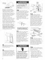
mmportant: Observe aH governing
codes and ordinances,
Proper installation is your
responsibility.
Make sure you have
everything necessary for correct
installation. It is the responsibility
of the installer to comply with the
installation clearances specified on
the model/serial rating plate.The
model/serial rating plate is located
on the front of the downdraft vent
above the wiring box cover.
Mobile home installation
The installation of this range hood
must conform to the Manufactured
Home Construction Safety
Standards, Title 24 CFR, Part 328
(formerly the Federal Standard for
Mobile Home Construction and
Safety, Title 24, HUD, Part 289) or
when such standard is not
applicable, the Standard for
Manufactured
Home Installation
1982 (Manufactured
Home Sites,
Communities and Setups) ANSI
A225.1/NFPA 591A*, or latest
edition, or with local codes.
Check location where downdraft
vent will be installed.The
location
should be away from strong draft
areas, such as windows, doors
and strong heating vents or fans.
Before making countertop cutout,
check that downdraft vent and
cooktop location will clear cabinet
walls, backsplash, and rear wall
studs inside cabinet.
ALL OPENINGS IN THE WALL OR
FLOOR WHERE RETRACTABLE
DOWNDRAFT VENT iS TO BE
INSTALLED MUST BE SEALED.
Electrical ground is required. See
"Electrical requirements;'
page 3.
When installing downdraft vent,
the cabinet drawer will need to be
removed and the drawer front
installed permanently to cabinet.
Note: Downdraft vent is installed
directly behind the cooktop. Install
downdraft vent first.
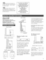
Cabinet construction:
Downdraft
vent is designed for use in a
cabinet with a depth of 24"
(61 cm). Some installations
require a countertop deeper than
25" (63.5 cmL See chart on page 5.
The maximum depth of the
overhead cabinet is 13" (33 cm).
Overhead cabinets installed at
either side of the downdraft vent
must be 18" (45.7 cm) above the
cooking surface.
See cooktop Installation
instructions before making any
cutouts and for the minimum
distance between the front edge
of the countertop and front edge
of cooktop.The minimum
horizontal distance between the
overhead cabinets is the same as
the width of the installed
downdraft vent.
When installing a 36" (91.4 cm)
retractable downdraft vent with
"Create-A-Cooktop"
modules, the
optional support must be installed
on the front of the downdraft vent.
See installation steps for details.
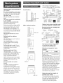
Parts supplied
for installation:
• t
2
•2
2
2
• 1
t
top trim
end cape
lower support legs
overcounter
support brackets
undemounter
mounting brackets
bag of fasteners
meta_ cover
• 1 backdraft damper
• literature package
• optional support and two screws
(36" (91.4 era) models only
Parts needed
for installation:
• 2 U.L.= or C.S.A.4isted 1/2" (12.7 ram)
conduit connectors
(3 are required if
the exterior-mounted
vent motor is
•
•
•
•
used.}
1 wall cap for interior-mounted
motor
vent system
power supply cable
wiring cable for optiona_ remote b_ower
kit.
Tools needed for
installation:
• safety glasses
• g_oves
• jig or keyhole saw
• drill with 118" drill bit
• pencil
• measuring tape
• flat=b_ade screwdriver
• Phillips screwdriver
• 318" (9.5 ram} nut driver
• leve_
• pliers
• metal snips
• wire stripper
caulking
• duct tape
gun
or ratchet
or utility knife
and weatherproof
caumk
important:
Observe aim governing
codes and ordinances.
it is the customer's
• To contact
installer.
• To assure
responsibimity:
a quamified
that
installation
conformance
emectricam
the electrical
is adequate
and in
with National
Electrical
Code, ANSi/NFPA
70
= latest edition%
or CSA
Standards
C22.1-94, Canadian
Electrical
Code, Part 1 and
C22.2 No. 0-M91 - latest
edition**
and all local codes
and ordinances.
if codes permit and a separate
ground
wire is used, it is
recommended
that a qualified
electrician
determine
that the
ground
path
i$ adequate.
Do not
ground
to a gas pipe.
Check with a qualified
electrician
if you are not sure downdraft
vent
is properly
grounded.
Do not
have a fuse
or ground
in the neutral
circuit.
iMPORTANT
Save installation
electrical
instructions
inspector's
for
use.
A 120-volt,
60-Hz, AC-only
electrical
supply is required
on a
separate
15-ampere
circuit, fused
on both sides of the line. A timedelay fuse or circuit
recommended.The
breaker is
fuse must be
sized per local codes in
accordance
with the electrical
rating of the downdraft
vent as
specified
on the model/serial
rating plate located on the front
of the downdraft
vent above the
wiring
box
cover.
THE DOWNDRAFT VENT
MUST BE CONNECTEDWITH
COPPER WIRE ONLY.
Wire sizes and connections
must conform to the
requirements of the National
Electrical Code, ANSI/NFPA 70 -latest edition% or CSA Standards
C22.1@4, Canadian Electrical
Code, Part 1 and C22.2 No. 0-M91
latest edition __ and all local
codes and ordinances.
WARNING -- TO REDUCE THE
RISK OF FIRE, ELECTRIC
SHOCK, OR INJURY TO
PERSONS, OBSERVE THE
FOLLOWING:
Installation work and electrical
wiring must be done by qualified
person(s) in accordance with all
applicabb Codes and Standards,
including fire related construction.
Sufficient air is needed for proper
combustion and exhausting of
gases through the flue (chimney)
of fuel burning equipment to
prevent back drafting. Follow the
heating equipment
manufacturer's guideline and
safety standards such as those
published by the National Fire
Protection Association
(NFPA),and the American Society
of Heating Refrigeration and Air
Conditioning Engineers
(ASHRAE), and the local code
authorities.
When cutting or drilling into wall
or ceiling, do not damage
electrical wiring and other hidden
utilities.
Ducted fans must always be
vented to the outdoors.
WARNING --To reduce the risk
of fire, use only metal ductwork.
This unit must be grounded.
This downdraft vent should
be connected directly to the fused
disconnect (or circuit breaker)
through flexible, armored or nonmetallic sheathed, copper cable.
Allow some slack in the cable so
the downdraft vent can be moved
if servicing is ever necessary.
E,,
A U.L.- or C.S.A.qisted, 1/2"
(12.7 ram) conduit connector
must be provided at each end of
the power supply cable (at the
downdraft vent and at the
junction box).
A wiring diagram is located
on the downdraft vent base
above the wiring box cover.
*
National Fire Protection
Batterymarch
Park
Quincy', Massachusetts
Association
02269
** Canadian Standard Association
178 Rexdale Boulevard
Etobicoke (toronto), Ontario MgW 1R3
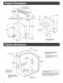
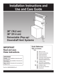
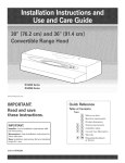
8=1/4"
(21cm)
retractable
vent height
-4
!9,5 mm)
3=1/4"x
10"
18,3 cmx 26.4 cm)
16"
140,6 cm)
I
9" (22.9 cm)
Diameter
5/_
{15.9 ram}
15"
(4&6 cm}
\
BLOWER
MOTOR
(20,8"cm)
4&6 cm
EXTERIOR=MOUNTED
BLOWER MOTOR
9=3/8"
123,8 cm)
(10.5 cm)
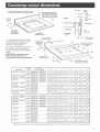
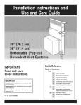
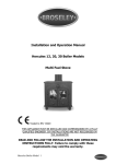
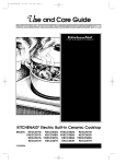
See cooktop
manufacturer's
instructions
for cooktop
cutout
depth
aed width_
Use dimensions
cutout
location
your installation_
for veet system
that applies
to
17=3/16"
(433 cm}
all cutouts are for
3=1/4" x 10"
(8.3 cmx 25.4 cm)
vent system
Locate power supply
junction box at lower
right hand rear corner of
cabinet,
Vent system cutout dimensions
blower models only.
for internal
Exterior mounted blower systems connect
with 10" (25.4 cm) roued vent.The cutout
locations for this vent system will depend
upon your specific iestaHation.
--
1o7/8"
/4.8 cm)
1/4"
1&4 ram)
A=1/2"
(12,7
ram}
rain,
1/2"
(12,7 mm}
rain,
cooktop
X
backsplash
countertop
j
1/4"
(&4 mm}
downdraft
vent
3/4"" (19.1
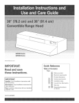
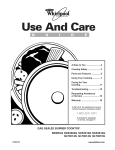
Htisrecommended
thatthecooktop
andventcutoutsbedrawnonthe
countertop
beforemakingany
cutoutstoavoidmistakes.
SeeCooktop
Installation
Hnstrucfions
forcompHete
cutoutdimensions,
Hocafion
dimensions
andinstallation
details.
IMPORTANT:
Countertops
with a
bulhosedfrontedge are not
recommended
for these
backsplash
1/2"" (12.7
minimum
splashguard
rear wall
turn}
_Jf
max
_1
I"_
1/2'_,(1,2'mTumm
m)
depth
ram)
to
Overall
and
or
depth of cooktop
downdraff
vent
system
H
installations.
Coo_op Models
Cooktop
Size
KGCT305G KGCSIO5G
30!'
Installedwith
VentSystemModels
A
B
C
D
E
F
G
H
KIRD801HSS KIRD802HSS
29"
27q/2"
19-5/8"
2q/8"
1-3/4"
31-3/8"
23"
25"
(76.2 ore) KIRDSOlXSS KIRDSO2XSS (73,7 cm) (6&9 em) (49.8 cm) (5.4 em) (4,4 cm) (7&7 cm) (58.4cm) (63,5 em)
KECC501G* KECCSO2G* 80"
KIRDSO1HSS KIRDSO2HSS 29q/2"
27q/2"
20q/2"
2q/8"
2"
31q/2"
23-!/4"
25-7/8"
KECC507G* KECC5OSG*(76.2 cm) KIRD801XSS KIRDSO2XSS (74.9 cm) (69,9 cm) (52,1 cm) (5,4 em) (5,1 cm) (80,0 em) (59,1cm) (65,7 em)
KECSIOOG*
30" ' KIRDSO1HSS KIRDSO2HSS 28-7/8" 27ol/2"
19"
2q/2"
3o3/8"
31q/2"
23"
25-5/8"
(76.2 cm)KIRDSOlXSS KIRDSO2XSS (73.3 cm) (69,9 em) (48,3 cm) (6,4 cm) (8,6 cm) (S&Ocm) (58,4cm) (65,1 em)
30?
GZ7930XGS
SCS3OO4G SCS3014G,
29"
27q/2"
19-5/8"
2q/8"
1-3/4"
31o3/8"
23"
25"
GLT3014G
(76.2 cm) GZ7930XHS
(73.7 cm) (69,9 em) (49,8 cm) (5,4 em) (4,4 cm) (79,7 cm) (58,4cm) (63,5 em)
RCC3024G* GJC3034G*
30'!
GZ7930XGS
29q/2"
27ol/2"
20q/2"
2"
2"
30"
23"
25-3/4"
(76.2 cm) GZ7930XHS
(74.9 cm) (69,9 em) (52,1 cm) (5,1 em) (5,1 cm) (76,2 em) (58,4cm) (65,4 em)
RCS3OO4G* RCS3014G* 301' GZ7930XGS
YRCS3014G*
(76.2 cm) GZ7930XHS
(73.3 cm) (69,9 cm) (48,3 cm) (6,4 em) (7,6 cm) (S&Ocm) (58,4cm) (64,8 em)
KGCT365G KECT366G
KGCS166G
KIRD861HSS KIRD862HSS
(9! .4 cm) KIRD861XSS KIRD862XSS
KECC562G* KECC567G* 36?
KECC568G*
KECS161G*
SCS3614G
GLT3614XG
GJC3634G*
KIRD861HSS KIRD862HSS
(91.4 cm) KIRD861XSS KIRD862XSS
36?
KIRD861HSS KIRD862HSS
35q/4"
27q/2"
2q/2"
19_5/8"
2ol/8"
(89,5cm) (8&9cm) (4&8cm)
(5.4cm)
35q/2"
33-1/2
19"
33q/2"
20q/2"
2q/8"
(90.2cm) (S&gcm) (52,1cm) (5,4em)
35"
33q/2"
19"
2q/2"
3"
1-3/4"
31q/2"
37q/2"
23"
23"
25q/2"
25"
(4,4cm) (9&3cm) (58.4cm) (63Scm)
2"
(SJcm)
3o3/8"
23q/4"
26o7/8"
37-5/8"
23"
25-5/8"
(88.9cm) (S&gem) (48,3cm) (6,4em)
GZ7936XGS
36!i
(9! .4 cm) GZ7936XHS
(89.5 cm) (85,9 cm) (49,8 cm) (5,4 em) (4,4 cm) (95,3 em) (58,4cm) (63,5 em)
GZ7936XGS
36!i
(91.4 cm) GZ7936XHS
(89.5 cm) (85,9 cm) (49,8 cm) (5,4 em) (4,4 cm) (9&Ocm) (58,4cm) (63,5 em)
36!I
GZ7936XGS
36'_
GZ7936XGS
(91.4 cm) GZ7936XHS
35q/4"
35-1/4"
35q/2"
33q/2"
33q/2"
33q/2"
19-5/8"
19-5/8"
20q/2"
2q/8"
2q/8"
2"
(&6cm)
37q/2"
(9&3cm) (59,1cm) (6&3em)
(9! .4 cm) KIRD861XSS KIRD862XSS
(91.4 cm) GZ7936XHS
RCS3614G*
28-7/8"
1-3/4"
1-3/4"
2"
(9&6cm) (58,4cm) (65,1 em)
37q/2"
36-5/8"
36"
23"
23"
23"
25"
25"
25-3/4"
(902 cm) (85,9 cm) (52.1 cm) (5.1 em) (5,1 cm) (91A cm) (58.4cm) (65,4 em)
35"
33q/2"
19"
2q/2"
3"
37-5/8"
23"
25-5/8"
(88.9 cm) (85,9 cm) (48,3 cm) (6,4 em) (7,6 cm) (95,6 cm) (58,4cm) (65,1 em)
* Installationwith vent system requirescountertop and base cabinetdeeper than standard 25" (63.5cm) deepcountertop and 24" (61,0 cm) deep base cabinet,
Vent system installed under a
concrete slab using PVC sewer pipe.
6" (15.2 cm) round
Venting system must terminate
the outside.
to
island location
metal vent
6" (15.2 cm)
transition
Do not terminate the vent system
in an attic or other enclosed area.
Do not use 4" (10.2 cm) laundry=
type wall caps
Do not use plastic or metal foil
vent.
Vent work needed for installation
is not supplied.
Wall cap is Not provided with
interior-mounted motor.
Determine which venting method
to use. Vent system can extend
through either the wall or roof.
6" (15,2 cm)
round 90°
PVC sewer
pipe elbow
Built-in
Tightly pack
gravel or sand
completely
around pipe.
6" (15,2 cm)
round 90 °
PVC sewer
pipe elbow
Optional vent system installed under
a concrete slab into a window well.
cabinet locations
#o not vent a gas cooktop
a window
well.
The length of vent system and
number of elbows should be kept
to a minimum to provide efficient
performance.
The size of the vent shouH be
uniform.
12" (30.5 cm)
6" (15.2 cm) routed
into
transition
Do Not install two elbows
together.
Use duct tape to seaU aH joints in
the vent system.
Use caulking tape to seaU the
exterior wall or floor opening
around cap.
round PVC
coupling
Do Not cut joist or stud. Ufvent
cutout faUUsover a joist or stud, a
supporting frame must be
constructed.
_eaF
vent
Flexible metal vent is Not
recommended.
Ufit is used,
caUcuhte each foot of fiexibUe vent
as two feet of rigid metaU vent.
Fbxible elbows count twice as
much as standard elbow, s.
Sea_ the space between
of wall cap in_et inside
coupling
with cauH{ing
the outside
of PVC
reetat.
Maximum
system
of vent
length
Vent
NOTE: Make sure there is proper
clearance within the wall or floor
before making exhaust vent
cutouts.
Recommended
vent system
length
For either interior-mounted
or
exterior-mounted
blow, er
installations, vent system length
should not exceed the maximum
lengths listed in the "Maximum
length of vent system" chart. (See
this page for Interior-mounted
vent motor; page 9 for exteriormounted vent motor.)
completely
around pipe,
Length
6" (15,2 cm) round
35 feet (8.9 re)
3ol/4" x 10"
(8.3 cre x 25,4 ere)
35 feet (8.9 re)
For best performance, use no more
than three go ° elbow's. If more than
one elbow, is used, make sure that
there is a minimum of 24" (61 cm) of
straight vent between any two
elbows. Do Not install two elbows
together. It is recommended that
you use round vent instead of
rectangular vent, especially if
elbows are required. If rectangular
vent is required, it should be
transitioned to 6" (15.2 cm) round
vent as soon as possible.
left vent
right
vent
Determining
the mength of
system you need:
To calculate the length of system
you need, add the equivalent feet
for each vent piece that will be
needed. See example for 6"
(15.2 cm) round vent system.
6" 115.2 cm) round
vent
over
counter
support
system
arm
J
mark
90 ° elbows
_-6
ft. (1,8 m) --}_1
ft, (9.6
Ma×imum
length
m)
= 35 ft. 1&9 m)
1 - wall cap
8 ft. (2.4 m) straight
2-90 ° elbows
=Off,
=8ft.
=10ft.
(0m)
(2.4 m)
(3m)
Transition
= 4.5 ft,
(1.4 m)
Length of 6""
(15.2 am) system
= 22.5 ft, (6.9 m)
Recommended
fittings
3-1/4" x 10"
(8.3 cmx 25,4 am)
to 6" (15,2 am}
= 4.5 ft. {1,4 m)
2m
Attach the left side and right
side overcounter support brackets
to the downdraft. Use 1 screw
with each bracket.
end
cap
_J
standard
\
3m
Attach the ]eft side and right
side end caps to the downdraft.
Use 1 screw with each end cap.
6" (15.2 am} to
3-1/4" x 10"
{8.3 cmx 25,4 am)
= 1 ft. {0.3 m}
upport
leg
6m
Move support
legs down
against cabinet floor. Place a level
against front of downdraft vent
base and adjust until downdraft
vent is level vertically. Use a
pencil to mark the top of each leg
on downdraft vent.Then mark
location of support leg mounting
holes on cabinet floor. Remove
downdraft vent from cutout. Drill
starter holes at each mounting
screw' location on cabinet floor.
Align top of legs with pencil
marks on face of downdraft vent.
Tighten screws in legs.
7_
Determine
which direction
(down, rear, left, or right) vent
will need to run from blower vent
when installed in cabinet.
Down venting:
3ol/4" x 10"
(8,3 cmx 25.4 am)
to 6" (15.2 am)
90° elbow =
5 ft. {1.5 m)
6" (15.2 am) to
3-1/4" x 10"
(&3 cmx 25.4 am)
90° etbow =
5 ft. (1,5 m)
4m
Attach support legs to side
of downdraft vent with 2 screw's
in each leg. Do not tighten
screws,
Left or right venting:
Excessive
90° elbow =
5 ft. (1.5 m)
Weight Hazard
Use two or more people to move
and install downdraft vent.
45 ° elbow
=
2.3 ft. (0.8m}
6" wall cap =
0ft,(0m)
l m Put on gbves and safety
gUasses. PUace cardboard or
another form of protection on top
of a fiat surface where you can
easily assemMe the downdraft
vent system. Remove parts
packages, downdraft vent and
bUower box from carton. Remove
aH shipping materials, tape and
protective film from downdraft
vent and blower box.
Downdraft vent is shipped with
blower in down venting position
so no modification
is required.
Go to Step 8.
Failure to do so can result in back
or other injury.
a. Remove 4 hex nuts that attach
blower box to downdraft vent
base. Remove blower box.
b, Rotate blower box 90 ° to left or
right so that vent blower is
repositioned
in the direction
needed.
c. Reattach blower box to
downdraft vent base with 4 hex
nuts.
Rear venting:
a. Remove 4 hex nuts that attach
blower box to downdraft vent
base. Remove blower box.
5m
Carefully
insert
downdraff
vent into countertop
cutout.Two
people are recommended
to
support
the weight
of the
downdraft
vent during
lifting.
Check that downdraft
vent is
parallel to side of cutout and that
mounting
brackets overlap
countertop.
b. Note how' wiring cable is
installed under plastic clips inside
vent base.Then carefully remove
wiring cable from plastic clips.
Disconnect blower wiring cable.
c. Remove 6 Phillips-head screws
attaching blower to blower box.
Remove blower.
bracket
rear
green
ground
for
screw
venting
Excessive
Weight Hazard
Use two or more people to move
and install downdraft vent.
Failure to do so can result in back
or other injury.
d, Remove screws attaching
brackets to each side of blower.
Reposkion brackets on blower as
shown.Then
reinstall screws.
e, Reinstall blower in blower box
with mouth of blower pointing out
open side of blower box. Secure
blower to blower box wkh 6
Phillips-head screws.
NOTE: Square metal frame
attached to mouth of blower must
be installed for proper operation.
lore
insert downdraft
vent
into countertop cutout.Two people
are recommended to support the
weight of the downdraft vent
during lifting. Position downdraft
vent so it is centered in cutout and
parallel to edge of cutout. Check
that downdraft vent is level
vertically.Then
fasten lower
support legs to cabinet floor with
screws.
f, Attach metal cover from parts
bag over downwenfing
knockout in
blower box. Remove rear knockout
cover on back of vent base.
g, Reconnect blower wiring cane.
Secure wiring came in 2 black
plastic clips inside vent base.The
wiring cable must be properly
secured in the 2 clips (see step b,}
Reattach blow, er box to downdraft
vent base vvkh 4 hex nuts.
wiring -'/
box
12m
conduit
connector
Remove
required
knockout
and install conduit
connector.
Feed the power supply
cane through
the conduit
connector
and into the wiring
box.
Connect
the white wires together
with a twist-on
wire connector.
Connect
the black wires together
with a twist-on
wire connector.
Attach the green (or green and
yellow)
ground
wire to eyelet with
green ground
screw.Tighten
the
conduit
connector
damp screws.
Reattach the wiring
box cover.
When
attaching
undercounter
bracket
to underside
of countertop,
make
sure that the screw
bngth
wiU not go
through
countertop
when tightened.
microswitches
behind filters.
ON/OFF
button
to
11m
Attach one undercounter
bracket on front upper right
corner of downdraft vent with slot
over vent mounting hob and
flange against countertop. Attach
other bracket to left side of
downdraft vent. Carefully drill
starter hobs through
undercounter
mounting brackets
into underside of countertop.
insert appropriate length screws
into hobs and tighten brackets to
countertop.
Attach backdraft damper
over blower box knockout vvkh 2
Phillips-head screws.
_fHter
or filters
depending
mode_
on
bbwer
eontro_
knob
\
end cap
13m
Turn power supply on.
Push and hold for a few' seconds
the button on the top of the
downdraft vent. Retractable section
of downdraft vent will rise and
blower will start. Position the top
trim over the retractable section
and snap trim into place.
14m
Turn the control knob on
side of vent to check the operation
and speed of blower.
m Remove the 2 Phillips-head
screws attaching the wiring box
cover. Determine which direction
(rear or down) electrical connection
vv,ill need to run from appliance
wiring box. Knock out rear or lower
wiring opening in wiring box.
Ebctrical
Shock Hazard
Disconnect power before
making electrical connections.
Connect ground wire to green
ground screw in terminam box.
Failure to do so can result in
death or ebctricaI shock.
if blower does not operate:
o Check that filter or filters are
pressed in as far as they will go.
o Check that circuit breaker is not
tripped or house fuse blown.
o Disconnect power source and
check that wire connections have
been made correctly.
5 mConnectvent systemto
blower.Ventsystemmustendwith
a wall or roof cap. Useducttape
to sealail joints.
Installcooktopaccording
to manufacturer'sinstructions.
Checkthat rearof cooktopoverlaps
edgeof retractabledowndraftvent
by 3/8"(9.5mm).
To get the most efficient
use from your new
retractable
downdra#
vent,
read the Use and Care
information
section
on
page 12.
Keep InstMlation
instructions
and Use and Care
information
close by for
easy reference.
KIRD and YKIRD
MODELS ONLY
Roof venting
it is recommended that you use
round vent instead of rectangular
vent, especially if elbows are
required, if rectangular vent is
required, it should be transitioned
to 10" (25.4 cm) round vent as
soon as possible.
NOTE: Exterior-mounted
vent
motor installations
require exterior
blower system, Part No,
KPED892K, available from your
dealer or authorized parts supplier.
Determining
you need:
island location
the length
of system
To calculate the length of system
you need, add the equivalent feet
for each duct piece that will be
needed. See example for 10"
(25.4 cm) round vent system.
F_
_J
'".,
10" (25,4 cm)
round
vent
10" (25.4
vent
Built-in
cabinet location
Maximum
system
era} round
svstem
_ength of vent
Vent
Length
10" (25,4 cm) round
40 ft. (12.2 m)
Vent length is given as a general
reference
only. For a longer vent
run, or smaller
vent system,
contact a qualified
and trained
vent installer.
Check with local
codes for makeup air
requirements,
if any.
E
Maximum
mength = 40 ft, (12,2 rn)
2-90elbows
=10
10 ft. (3m) straight=10
Built-in
left vent
cabinet location
right
vent
For best performance,
use no more
than three g0 ° elbows, if more than
one elbow is used, make sure that
there is a minimum of 24 inches
(61 cm) of straight vent between
any two elbows. Do Not install two
elbows together.
Length of 10"
(25.4 cm) system
ft.
(3m)
ft.
(3m)
= 20 ft. (6.1 m)
Note:The exterior-mounted
vent
motor requires a separate wiring
cable that should be installed at
the same time the vent work is
installed.
9
Recommended
fittings
standard
.!support
leg
cabinet floor. AUign top of bgs
with pencil marks on face of
downdraft vent.Tighten
screws in
Uegs.
,, Attach 10" (25.4 cm) round
90° elbow =
5 ft., (1,5 m)
l
45° elbow =
£5 ft_
(&8 m)
4m
Attach support Uegs to side of
downdraft vent with two screw's in
each Ueg. Do Not tighten screws.
Excessive
m Put on gloves and safety
glasses. Place cardboard or another
form of protection on top of a flat
surface where you can easily
assemble the downdraft vent
system. Remove parts packages,
downdraft vent and blower box
from carton. Remove all shipping
materials, tape and protective film
from downdraft vent and blower
box.
Weight Hazard
Use two or more people to move
and install downdraft vent,
Faiture to do so can result in back
or other injury.
vent collar pUate (suppUied wkh
exterior Mower system) to front of
downdraft vent using 4 hex washer
nuts.
Remove the 2 Phillips-head
screws attaching the wiring box
cover and remove cover. Remove
either the back or bottom knockout
and install conduit connector.
Power supply cable needed
between exterior blower assemblv
and blower box is not provided.
9m
Determine the location where
the exterior blower box wiil be
located. Cut opening in roof or wail
for vent system to exterior blower.
install exterior blower according to
instructions supplied with the
blower kit.
Wail installations
5m
2m
Attach the left side and right
side overcounter support brackets
to the downdraft. Use 1 screw
with each bracket.
Carefully
insert
downdraft
vent into countertop
cutout.Two
people are recommended
to
support the weight of the
downdraft
vent during lifting.
Check that downdraft
vent is
parallel to side of cutout and that
mounting
brackets rest gently on
countertop.
o Use caulking compound between
mounting flange and wall.
Roof Installations
o Follow standard
procedures.
roofing
o The flashing sheet should be
entered over the roof opening.
o Lower edge of flashing should lie
on top shingles and upper edge
underneath shingles.
o Seal assembly between roof, fan
and flashing with roofing mastic
to prevent leaks.
\
3m
Attach the left side and right
side end caps to the dow'ndraft.
Use 1 screw with each end cap.
6m
Move
legs down
against cabinet floor. Place a level
against front of downdraft
vent
base and adjust position
of legs
until downdraft
is level vertically.
Use a pencil to mark the top of
each leg on face of downdraft
vent.
Then mark location
of support
leg
mounting
holes on cabinet floor.
Remove downdraft
vent from
cutout. Drill starter holes at each
mounting
10
support
screw'
location
on
microswitehes
IOta
behind filters.
insert retractable
downdraft vent into countertop
cutout.Two people are
recommended to support the
weight of the downdraft vent
during lifting. Position downdraft
vent so it is centered in cutout and
parallel to edge of cutout, Check
that downdraft vent is vertical.Then
attach lower support legs to cabinet
floor wkh screws,
vent box
knockout
...wiring
box
cover
green
ground
screw
green
wire
/
1 m Attach one undercounter
mounting bracket on front upper
right corner of downdraft vent
with slot over vent mounting hole
and flange against countertop.
Attach other bracket to left side of
downdraft vent. Carefully drill
starter hobs through
undercounter
mounting brackets
into underside of countertop.
insert appropriate length screws
into holes and tighten brackets to
countertop.
on
\
end cap
14_
Turn power supply on.
Push and hold for a few seconds
the button on the top of the
dovvndraft vent. Retractable
section of downdraft vent will rise
and blower will start. Position the
top trim over the retractable
section and snap trim into place.
connector
When
attaching
undercounter
bracket
to underside
of countertop,
make
sure that the screw
length
will not go
through
countertop
when
tightened,
depending
mode_
2 m Feed the power supply
cable through the conduit
connector and into wiring box.
Connect the white wires together
with a twist-on wire connector.
Connect the black wires together
with a twist-on wire connector.
Attach the green (or green and
yellow) ground wire to eyelet with
green ground screw and tighten
screw. Replace wiring box cover.
5 m Turn the control knob on
side of vent to check the
operation and speed of blower.
if blower does not operate:
o Check that filter or filters are
pressed in as far as they will go.
o Check that circuit breaker is not
tripped or house fuse blown.
o Disconnect power source and
check that wire connections
have been made correctly.
green
screw
-- green
/
/\
j
ground
/
wire
16m
Connect vent to blower.
Position vent to avoid wall studs
and floor joists. Complete all vent
work. Use duct tape to seal all
joints. Vertical vent for walP
mounted installations should pitch
down slightly toward the vent to
allow moisture to run outside.
exterior-mounted
vent motor wiring
m Remove vent box
Electricam Shock Hazard
Disconnect power before
making electricam connections.
Connect ground wire to green
ground screw in terminaI box.
Failure to do so can result in
death or electrical shock.
knockout and install conduit
connector.
Feed exterior-mounted
vent motor
wiring through conduit connector.
Do not wire the exterior vent
motor black and white wires into
the wiring box.Wires must be
connected as shown. Connect the
white wires together with a twiston wire connector. Connect the
black wires together with a twiston
connector.
Attach ground wire to eyelet with
green ground screw and tighten
screw.
Tighten conduit
screw's.
connector
clamp
17_
Install cooktop
according
to manufacturer's
instructions.
Check that rear of cooktop
overlaps
edge of retractable
downdraft
vent
by 3/8" (9.5 ram).
To get the most efficient
use from your new
retractable
downdraft
vent,
read the Use and Care
information
section on
page 12.
Keep Installation
instructions
and Use and Care
information
ctose by for
easy reference.
11
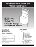
Theretractabbdowndraftventsystemis designed
to removesmoke,cookingvaporsandodorsfromthecooktoparea.
Forthebestresuks,theventshouldbeoperatingbeforecookingisstarted.If youuselargeor tall utensils,placethem
onthelargerearebmentor burnersurface.A higherheatsettingthannormallyusedmaybeneededwhenthe
down@aft
ventis operating.
WARNING--TO REDUCETHE
RiSKOFFIRE,
ELECTRIC
SHOCK,ORINJURYTOPERSONS,
OBSERVETHE
FOLLOWING:
Usethis unit only in the mannerintendedby the
manufacturer,if you havequestions,contactthe
manufacturer.Beforeservicingor cleaningunit,
switchpoweroff at servicepanelandlockthe service
disconnectingmeansto preventpowerfrom being
switchedon accidentally.
Whenthe service
disconnectingmeanscannotbelocked,securely
fastena prominentwarningdevicesuchas a tag to
the servicepanel.
CAUTION:Forgeneralventilatinguseonly.Donot
useto exhaust hazardous or explosive materials and
vapors.
WARNING --TO
GREASE FIRE:
REDUCETHE RiSK OF A RANGETOP
Never leave surface units unattended at high
settings. Boilovers cause smoking and greasy
spillovers that may ignite. Heat oils slowly on low or
medium settings.
Always turn hood ON when cooking
when cooking flaming foods.
at high heat or
Use proper pan size. Always use cookware
appropriate for the size of the surface element.
WARNING --TO REDUCETHE RiSK OF INJURYTO
PERSONS INTHE EVENT OF A RANGETOP GREASE
FIRE, OBSERVETHE FOLLOWING:
SMOTHER FLAMES with a close-fitting lid, cookie
sheet, or metal tray, then turn off the burner. BE
CAREFULTO PREVENT BURNS.
if the flames do not go out immediately, EVACUATE
AND CALLTHE FiRE DEPARTMENT.
NEVER PiCK UP A FLAMING PAN --You
burned.
may be
DO NOT USE WATER, including wet dishcloths or
towels-a violent steam explosion will result. Use
an extinguisher ONLY if:
You know you have a Class ABC extinguisher,
you already know how to operate it.
The fire is small and contained
is started.
The fire department
and
in the area where
it
is being called.
You can fight the fire with your back to an exit.
Clean ventilating fans frequently. Grease should not
be allowed to accumulate on fan or filter.
This fan is suitable for use with
solid-state speed controls.
Operating
downdraft
vent
Push and hold for a few seconds
the button on top of downdraft
vent. This slight delay prevents
raising the vent during cleaning.
Retractable section of downdraft
vent wiil rise and blower wiil
begin to vent.Turn knob on side
of downdraft vent to adjust the
setting to the amount of venting
you need. The knob has infinite
settings. Place cooking utensils
on cooking surface and turn
cooking unit on. When cooking is
complete, turn cooking unit off,
remove utensils from cooking
surface, and push button on top
of retractable downdraft vent.
The blower will turn off and the
retractable section of the vent will
return to the closed position.
12
if a spill occurs on the cooktop
that allows liquids to seep inside
the downdraft, you must turn the
downdraft off immediately,
it is
possible to cause damage to the
downdraft if water is allowed
inside the downdraft while it is
operating.
, Immediately turn OFF the
downdraft at the speed control
located on the right-hand side
of the downdraft.
, Turn OFF the power supply to
the downdraft at the circuit
breaker box or fuse box.
Allow plenty of time for the
downdraft to dry naturally. Do
not open the downdraft to
remove the water.
Cleaning
Surface of downdraff vent: Clean
with soap and water. Do Not use
scouring powder or abrasive
solutions.
Filter or filters (depending on
model): Frequently remove and
clean the filters in the retractable
section of the downdraft vent.
This will improve the operating
efficiency of the downdraft vent
system.
1. Remove the filter(s) and clean
them in the dishwasher or in a
hot detergent solution.
Do Not use the downdraft vent
when the filter(s) is not in place.
2, Reinstall the clean filter(s),
making sure that they are pushed
in as far as they will go.
Note: Downdraft vent will not
operate if filter(s) is not in proper
position, if the handle(s) is not
fully locked, the vent may retract
but not raise back up.
if retractable downdraft vent
does not operate after clean
filters have been reinstalled:
Push the fiker in as far as it w,iH
go. When the filter is removed,
the microswitch
behind the filter
is inactivated.This
safety feature
stops the bUower and raising
mechanism until the filter is
propedy reinstalled.
rnieroswitehes
behind
Note: Instructions
with each kit.
filters
dels with
o filters
filter
\
microswitches
behind
filter
models
with
one filter
are included
For model series
KIRD &YKIRD 801,802
For model series
GZ &YGZ 7930
30" (76.2 cm) one=piece trim:
Part No. 8171304 (white)
Part No. 8171305 (black)
Part No. 8171306 (biscuit)
30 °°(76.2 cm) one-piece trim:
Part No. 8171300 (white)
Part No. 8171301 (black)
Part No. 8171370 (biscuit)
For model series
KIRD &YKIRD 861,862
For model series
GZ &YGZ 7736
36" (91.4 cm} one=piece trim:
Part No. 8171310 (white)
Part No. 8171311 (black)
Part No. 8171312 (biscuit)
36" (91.4 cm} one=piece trim:
Part No. 8171302 (white)
Part No. 8171303 (black)
Part No. 8171371 (biscuit)
LENGTH OF WARRANTY
WARRANTY WILL PAY FOR
ONE-YEAR FULL WARRANTY
From Date of Purchase
Labor and any parts of your vent system (except filters)
which are defective in materials or workmanship.
WARRANTY WILL NOT PAY FOR
A. Any labor costs incidental
B. Consumable
to the replacement
of defective
parts during the warranty
period.
parts such as light bulbs and filters.
C. Service calls to:
1. Correct the installation of the vent system.
2. Instruct you how' to use the vent system.
3. Replace house fuses or correct house wiring.
D. Repairs when vent system is used in other than normal,
E. Pickup and delivery.This
product is designed
E Damage to vent system caused by accident,
byWhidpool.
G. Repairs to parts or systems resulting
H. Replacement
I.
single-family
household
use.
to be repaired in the home.
misuse, fire, flood, act of God or use of products
from unauthorized
modifications
not approved
made to the appliance.
parts or repair labor costs for units outside the United States or Canada.
In Canada, travel or transportation
expenses for customers
who reside in remote areas.
WHIRLPOOL, INGLIS LIMITED, KITCHENAID ®and KITCHENAID CANADA DO NOT ASSUME ANY RESPONSIBILITY
FOR INCIDENTAL OR CONSEQUENTIAL DAMAGES. Some states or provinces do not allow the exclusion or limitation of incidental or consequential damages, so this exclusion or limitation may not apply to you.
This warranty gives you specific legal rights, and you may also have other rights which
state or province to province.
Outside the United States and Canada, a different
authorized dealer.
warranty
may apphi. For details,
may vary from state to
please contact your
13
Identifythe brandof your vent systemand,as
appropriate,callthe KitchenAidCustomer
InteractionCentertoll-freeat 1-800-422-1230
or call
theWhirlpoolCustomerInteractionCentertoll=free
at 1-800-253-1301.
Ourconsultantsareavailableto
assist you.
When calling: Please know the purchase date, and the complete model
and serial number of your appliance
This information w,ill help us better
respond to your request.
Our consultants provide assistance with:
Features and specifications on our full line
of appliances
ff you need replacement
parts
o Installation
Use and maintenance
procedures
® Accessory
and repair parts sales
® Specialized
customer
assistance
(Spanish
speaking,
hearing
impaired,
limited vision,
etc.)
® Referrals to local dealers,
service companies,
and
repair parts distributors
Whirlpool-designated
service technicians are trained to
fulfill the produc:t warranty and provide after-warranty
service, anywhere in the United States.
To locate
service
company
in your
directory
For further assistance
if you need further assistance, you can write to
Whirlpool Corporation or KitchenAid with any
questions
or tell us about
Customer
interaction
c/o Correspondence
2000 North M-63
Benton
To locate factory-authorized
parts in your area, call
our Customer interaction Center telephone numbem
your nearest authorized service center, or Factory
Service at 1-800-442-1111.
When asking for assistance or
service, please provide a detailed
description of the problem, your
appliance's complete model and
serial numbers, and the purchase
date.This information will help us
respond properly to your request.
the designated
area, you can also look in your telephone
Yellow Pages.
if you need to order replacement parts, we
recommend that you only use factory-authorized
parts.These parts will fit right and work right,
because they are made to the same exacting
specifications
used to build every newWhirlpool
or KitchenAid appliance.
Call toll-free,
8:30 a.m. to 6 p.m. (EST) at
1-800-422-1230.
Or contact
your nearest
lnglis
Limited
or Kitchenaid
Canada Appliance
Service
branch or designated
servicing
outlet
(see list at
right} to service your appliance,
information
Harbor,
Please include
correspondence.
Direct serv{ce
BRmSH
your
concerns
at:
Center
Dept.
MI 49022-2692
a daytime
phone
number
in your
branches:
COLUMBIA
1-800-665-6788
ALBERTA
1-800-661-6291
ONTARBO
Ottawa area
1-800-267-3456
(except
Outside the Ottawa area
1-800-807-6777
807 area code}
MANITOBA, SASKATCHEWAN
and 807 area code in ONTARIO
1-800-665-1683
QUEBEC
Montreal (except South Shore)
South Shore Montreal
1-800-361-3032
1-800-361-0950
Quebec City
Sherbrooke
1-800-463-1523
1-800-567-6966
ATLANTIC
PROVINCES
1-800-565-1598
For further assistance
If you need further assistance, you can write to
Inglis Limited or KitchenAid Canada with any questions
or concerns at:
Please include a daytime phone number in your
correspondence.
Consumer Relations Department
1901 Minnesota Court
Mississauga, Ontario L5N 3A7
Part No. 4329225/8284826 Rev. A
© 2002 Whirlpool Corporation
® Registered trademark/TM trademark of KitchenAid, U.S.A. KitchenAid Canada licensee in Canada
Benton Harbor, Michigan 49022