1
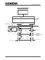
TC12 General Handbook
SIEMENS TRAFFIC CONTROLS,
Sopers Lane,
POOLE, Dorset.
BH17 7ER.
SYSTEM: TC12
TC12 General Handbook
PREPARED:
A Pickering
FUNCTION:
Engineer
This document is electronically held and approved
ISSUE:
1
2
3
4
5
6
7
8
9
REF:
DATE:
TS003024
19/12/92
19/01/93
05/05/93
28/04/94
08/05/97
26/01/99
20/06/00
09/01/02
13/01/2006
© Siemens plc. 2002 All rights reserved.
The information contained herein is the property of Siemens plc. and is supplied without liability for errors
or omissions. No part may be reproduced or used except as authorized by contract or other written
permission. The copyright and the foregoing restriction on reproduction and use extend to all media in
which the information may be embodied.
666/HB/43100/000
Page i
Issue 9
TC12 General Handbook
ISSUE STATE
Note :- Source of documents is shown under Type as below.
1=Paper, 2=VAX, 3=Microfilm, 4=CALTEXT Disc, 5=DECmate Disc,
6=Paper Insert, 7=MAC Disc, 8=LIFESPAN, 9=SUN, 10=Meridian
The document comprises the following components :-
Pages
Current
Issue
Type
Part ID
i to viii
9
10
666/HB/43100/000
1-1
9
10
666/HB/43100/000
2-1 to 2-4
9
10
666/HB/43100/000
3-1
9
10
666/HB/43100/000
4-1 to 4-7
9
10
666/HB/43100/000
5-1 to 5-18
9
10
666/HB/43100/000
6-1
9
10
666/HB/43100/000
Insert the following documents / drawings at the end of this document, use the latest issue available.
DRAWINGS TO BE A3 - DOCUMENTS AT A4.
666/HE/43100/000
AND ALL DRAWINGS/DOCUMENTS ASSOCIATED WITH IT.
666/HB/43100/000
Page ii
Issue 9
TC12 General Handbook
SAFETY WARNING
In the interests of health and safety, when using or servicing this equipment the following instructions
must be noted and adhered to:
i. Only skilled or instructed personnel with relevant technical knowledge and experience, who are also
familiar with the safety procedures required when dealing with modern electrical/electronic equipment
are to be allowed to use and/or work on the equipment. All work shall be performed in accordance
with the Electricity at Work Regulations 1989.
ii. Such personnel must take heed of all relevant notes, cautions and warnings in this handbook, the
General Handbook (666/HB/43100/000) and any other document or handbook associated with the
equipment.
(a) The equipment must be correctly connected to the specified incoming power supply.
(b) The equipment must be disconnected/isolated from the incoming power supply before removing
protective covers or working on any part from which protective covers have been removed.
666/HB/43100/000
Page iii
Issue 9
TC12 General Handbook
TELECOMMUNICATIONS APPROVAL WARNING
The TC12 Modems 667/1/22669/000, 667/1/22668/000 and 667/1/22668/001 and the TC12 OTU/LMU
PCB Assemblies 666/1/02262/001 and 666/1/02262/021 are Approved for connection to British
Telecommunications Private Circuits in a Multipoint or Point to Point configuration as defined in BS6328:
Part 1: 1982, subject to the conditions set out in the instructions for use.
TC12 Modems
Approval Number: NS/1143/2/N/603301
Date: 18/8/92
TC12 OTU/LMU PCB
Approval Number: NS/1143/2/N/603385
Date: 10/11/92
The Modem apparatus is intended for use when supplied with power from a source with the following
characteristics: +5V (700mA), +12V (110mA) and -12V (160mA). Ensure that the power drawn by this
modem together with any other auxiliary apparatus drawing power from the host, lies within the rating of
the host power supply. The OTU/LMU is intended for use when supplied with power from a source with
the following characteristics: +5V (2.2A), +24V (250mA). Ensure that the power drawn by the OTU/LMU
together with any other auxiliary apparatus drawing power from the host, lies within the rating of the host
power supply. Other usage will invalidate any approval given to this apparatus if as a result it ceases to
comply with BS6301: 1989.
This apparatus is NOT suitable for connection to the PSTN or to circuits with British Telecommunications
signalling at a nominal frequency of 2280Hz. It is not intended that there shall be any d.c. interaction
between this apparatus and British Telecommunications private circuits, nor does this apparatus use the
frequency range d.c. to 200Hz.
The approval of this apparatus for connection to British Telecommunication Private Speechband circuits
is INVALIDATED if the apparatus is subject to any modification in any material way not authorized by
BABT or its use with, or connected to :(i) internal software that has not been formally accepted by BABT.
(ii) external control software or external control apparatus which causes the operation of the modem or
associated call set-up equipment to contravene the requirements of the standard set out in
BABT/SITS/82/01/C.
All apparatus connected to this modem and thereby connected directly or indirectly to British
Telecommunication Private Speechband circuits must be approved apparatus defined in Section 16 of
the British Telecommunication Act 1981.
The TC12 Instation 667/1/22600/ETC is covered by the General Approval for indirect connection of
apparatus under Section 22 of the 1984 Telecommunications Act, Approval no. NS/G/1234/J/100003.
The mark of approval for the TC12 modem must NOT be applied to the Instation as a whole.
TheTC12 Freestanding OTU/LMU 667/1/22670/ETC is covered by the General Approval for indirect
connection of apparatus under Section 22 of the 1984 Telecommunications Act, Approval no.
NS/G/1234/J/100003. The mark of approval for the TC12 OTU/LMU PCB Assembly must NOT be applied
to the TC12 Freestanding OTU/LMU mechanics as a whole.
This Handbook must be supplied with the apparatus. Validity of the approval depends on this information
being supplied including the User Guide in the General Handbook 666/HB/43100/000.
666/HB/43100/000
Page iv
Issue 9
TC12 General Handbook
PREFACE
It is intended that this preface should guide the reader as to the use of this handbook, thus assisting the
reader in selecting the best section to read in order to obtain the information required.
Section 1
Introduction:- An introduction to both the handbook and the TC12 system.
Section 2
Specification:- This gives values and ranges for the following items:
Weight, Size, Currents, Voltages, etc.
Section 3
Modem User Guide.
Section 4
System Hardware:- A basic description of the hardware used in TC12.
Section 5
System Facilities:- A complete list of the facilities provided by a TC12 system.
Section 6
Integral OTU.
666/HB/43100/000
Page v
Issue 9
TC12 General Handbook
TABLE OF CONTENTS
1.
INTRODUCTION ............................................................................................................................ 1-1
1.1
1.2
1.3
1.4
2.
Purpose....................................................................................................................................... 1-1
Related documents ..................................................................................................................... 1-1
Definitions ................................................................................................................................... 1-1
Summary of Major Changes ....................................................................................................... 1-1
SPECIFICATION ............................................................................................................................ 2-1
2.1
Mains Voltage Ranges................................................................................................................ 2-1
2.2
Mains frequency range ............................................................................................................... 2-1
2.3
Mains Current ............................................................................................................................. 2-1
2.3.1
Instation ............................................................................................................................... 2-1
2.3.2
Outstation............................................................................................................................. 2-1
2.3.3
Test Sets.............................................................................................................................. 2-1
2.4
Temperature and Humidity Requirements.................................................................................. 2-1
2.5
Size and Weight.......................................................................................................................... 2-2
2.5.1
Instation ............................................................................................................................... 2-2
2.5.2
Outstation............................................................................................................................. 2-2
2.5.3
Instation Test Set................................................................................................................. 2-2
2.5.4
Outstation Test Set .............................................................................................................. 2-2
2.6
Approvals .................................................................................................................................... 2-2
2.6.1
British Telecom .................................................................................................................... 2-2
2.6.2
Department of Transport...................................................................................................... 2-2
2.6.3
Other Approvals................................................................................................................... 2-2
2.7
General Overview ....................................................................................................................... 2-3
3.
MODEM USERS GUIDE ................................................................................................................ 3-1
4.
SYSTEM HARDWARE................................................................................................................... 4-1
4.1
General ....................................................................................................................................... 4-1
4.2
UTC Traffic Control Computer System ....................................................................................... 4-1
4.3
Instation....................................................................................................................................... 4-1
4.4
Test Sets ..................................................................................................................................... 4-2
4.4.1
Instation Test Set................................................................................................................. 4-2
4.4.2
Outstation Test Set .............................................................................................................. 4-2
4.5
Freestanding Outstation.............................................................................................................. 4-2
5.
SYSTEM FACILITIES..................................................................................................................... 5-1
5.1
General System .......................................................................................................................... 5-1
5.1.1
Baud Rate ............................................................................................................................ 5-1
5.1.2
Modem Signal Levels .......................................................................................................... 5-1
5.1.3
Connection to Leased Telephone Line................................................................................ 5-1
5.1.4
Number of OTUs per Line ................................................................................................... 5-2
5.2
Instation Facilities ..................................................................................................................... 5-11
5.2.1
The System Fault Indication Panel.................................................................................... 5-11
5.2.2
Modem fault indication....................................................................................................... 5-11
5.2.3
Fault Actions ...................................................................................................................... 5-11
5.2.4
PSTN Modem .................................................................................................................... 5-11
5.2.5
TC8 Integration .................................................................................................................. 5-11
5.2.6
Digital Output Facilities ...................................................................................................... 5-11
5.3
Free-standing Outstation Facilities ........................................................................................... 5-13
5.3.1
Handset.............................................................................................................................. 5-13
5.3.2
OTU Inputs and Outputs.................................................................................................... 5-13
5.3.3
Indicators ........................................................................................................................... 5-13
5.3.4
Fault Action ........................................................................................................................ 5-13
5.3.5
Remote Controller Handset ............................................................................................... 5-13
5.3.6
Instation Communications Method .................................................................................... 5-14
666/HB/43100/000
Page vi
Issue 9
TC12 General Handbook
5.4
Lamp Monitoring Facilities ........................................................................................................ 5-14
5.4.1
General .............................................................................................................................. 5-14
5.4.2
Red Lamp Monitoring ........................................................................................................ 5-15
5.5
Detector Fault Monitoring (DFM) .............................................................................................. 5-15
5.6
High Occupancy Software (HIOCC) ......................................................................................... 5-16
5.6.1
General .............................................................................................................................. 5-16
5.6.2
Hardware ........................................................................................................................... 5-16
5.6.3
Software............................................................................................................................. 5-16
5.6.4
Configurable options.......................................................................................................... 5-17
5.6.5
Instation Test Set............................................................................................................... 5-17
5.6.6
Monitor Mode ..................................................................................................................... 5-17
5.6.7
Instation Mode ................................................................................................................... 5-17
5.6.8
Outstation Mode ................................................................................................................ 5-18
5.6.9
Data Displayed by the ITS ................................................................................................. 5-18
5.6.10 Idle Condition ..................................................................................................................... 5-18
5.7
Outstation Test Set ................................................................................................................... 5-18
6.
INTEGRAL OUTSTATION TRANSMISSION UNIT (OTU) ............................................................ 6-1
6.1
6.2
6.3
General Overview ....................................................................................................................... 6-1
Indicators..................................................................................................................................... 6-1
Fault Action ................................................................................................................................. 6-1
FIGURES
Figure 1 - OVERVIEW OF TC12 SYSTEM ............................................................................................... 2-4
Figure 2 - INSTATION CABINET .............................................................................................................. 4-3
Figure 3 - ITU RACK ................................................................................................................................. 4-4
Figure 4 - DIGITAL OUTPUT RACK ......................................................................................................... 4-5
Figure 5 - OTU RACK................................................................................................................................ 4-5
Figure 6 - INSTATION TEST SET............................................................................................................. 4-6
Figure 7 - OUTSTATION TEST SET......................................................................................................... 4-7
Figure 8 - MESSAGE FORMAT - FULL AND HALF DUPLEX ................................................................. 5-3
Figure 9 - INSTATION SYSTEM ............................................................................................................. 5-12
TABLES
Table 1 - MODEM CAPACITY .................................................................................................................. 5-4
Table 2 - OTUS PER LINE (1200 BAUD FULL DUPLEX) ........................................................................ 5-5
Table 3 - OTUS PER LINE (1200 BAUD HALF DUPLEX) ....................................................................... 5-6
Table 4 - OTUS PER LINE (600 BAUD FULL DUPLEX) .......................................................................... 5-7
Table 5 - OTUS PER LINE (600 BAUD HALF DUPLEX) ......................................................................... 5-8
Table 6 - OTUS PER LINE (300 BAUD FULL DUPLEX) .......................................................................... 5-9
Table 7 - OTUS PER LINE (300 BAUD HALF DUPLEX) ....................................................................... 5-10
666/HB/43100/000
Page vii
Issue 9
TC12 General Handbook
1. INTRODUCTION
1.1 Purpose
This document describes to the user the TC12 Traffic Control Data Transmission System, which
consists of an Instation, an Outstation, an Instation Test Set and an Outstation Test Set.
1.2 Related documents
666/HE/43100/000
TC12 Installation, Commissioning and Maintenance Handbook.
1.3 Definitions
BABT
BT
DFM
DSP
IMD
I/O
ITU
ITS
OTU
OTS
PC
PSTN
RAM
RLM
SCOOT
TCC
UTC
British Approvals Board for Telecommunications
British Telecom
Detector Fault Monitoring
Digital Signal Processor
Intelligent Modem Driver
Input/Output
Instation Transmission Unit
Instation Test Set
Outstation Transmission Unit
Outstation Test Set
Personal Computer
Public Switched Telephone Network
Random Access Memory
Red Lamp Monitoring
Split Cycle Offset Optimisation Technique
Traffic Control Computer
Urban Traffic Control
1.4 Summary of Major Changes
OTU / Instation RS232 communications added
.
666/HB/43100/000
Page 1-1
Issue 9
TC12 General Handbook
2. SPECIFICATION
2.1 Mains Voltage Ranges
Instation
98 - 132Vrms / 198 - 264Vrms
Outstation
85 - 264Vrms
Instation Test Set
98 - 132Vrms / 198 - 264Vrms
Outstation Test Set
99 - 121Vrms / 216 - 264Vrms
2.2 Mains frequency range
All TC12 equipment will work from 47Hz to 63Hz.
2.3 Mains Current
2.3.1 Instation
Instation Cabinet without racks
1.0A at 240V
ITU Rack (Fully equipped)
200mA at 240V
Digital Output Rack (Fully equipped)
1024 LEDs at 24V 25mA per LED
4.5A at 240V
Digital Output Rack (Fully equipped)
1024 LEDs at 24V 15mA per LED
2.75A at 240V
The figures above are added together for the system used:
An Instation cabinet with two ITU racks
1.0 + 0.2 + 0.2 = 1.4A
An Instation cabinet with two 15mA Digital output racks
1.0 + 2.75 + 2.75 = 6.50A
2.3.2 Outstation
OTU rack including 4 Detector cards
250mA at 240V
2.3.3 Test Sets
Instation Test Set
400mA at 240V
Outstation Test Set
100mA at 240V
2.4 Temperature and Humidity Requirements
Instation will work at 0 to 40 Deg C.
Humidity 20%-80% non-condensing.
OTU will work at -15 to 75 Deg C.
Humidity 96% at 40 Deg C non condensing.
666/HB/43100/000
Page 2-1
Issue 9
TC12 General Handbook
2.5 Size and Weight
2.5.1 Instation
Height
Width
Depth
1601mm
600mm
800mm
Cabinet
ITU Rack
Digital Output Rack
111Kg
8.4Kg
8.3Kg
NOTE : The weight of the cabinet does not include any of the PC equipment, and the weights
specified for the racks are with their full complement of PCBs.
2.5.2 Outstation
Height
Width
Depth
Weight
222.3mm
482.6mm
305.0mm
5.4Kg
NOTE: The weight of the OTU does not include detectors or their backplanes.
2.5.3 Instation Test Set
Height
Width
Depth
Weight
530mm
354mm
215mm
13Kg
2.5.4 Outstation Test Set
Height
Width
Depth
Weight
191mm
330mm
229mm
6Kg
2.6 Approvals
2.6.1 British Telecom
The TC12 Instation and Outstation are covered by BABT approval for connection to British
Telecommunications private circuits.
2.6.2 Department of Transport
The TC12 System is approved to DTp Specification MCE0361.
2.6.3 Other Approvals
As required by the appropriate authorities for the numerous countries where the system may be
installed and shall only be obtained as part of a contract requirement.
666/HB/43100/000
Page 2-2
Issue 9
TC12 General Handbook
2.7 General Overview
TC12 is a telecommunications system designed for Urban Traffic Control (UTC).
It consists of a number of Outstation Transmission Units (OTUs) positioned in traffic controller or
detector cabinets. The OTUs communicate with a Central Office containing one or more Instations.
Communication between the OTU and an Instation is by means of a) telephone (normally leased)
lines, which can be operated at different baud rates and signal levels or b) RS232 serial links which
can be operated at the same baud rates as the telephone lines.
The Instation periodically sends a Control message to the OTU which will cause the OTU to form
the appropriate Reply message which it will send back. These messages are of configurable size
depending on the amount of data transfer needed.
The Instation connects via an ethernet link to a Traffic Control Computer (TCC) system consisting
of one or more computers. This system drives the Instation modems, which communicate with the
OTU via the telephone lines. The modems are not provided where RS232 serial links are required.
The Instation also drives the System Fault Indication Panel (SIP) which indicates, by means of
LEDs and an audible alarm, failures in the TCC. The SIP is housed in the Instation cabinet but
there is also the option of driving a remote SIP. The TC12 Instation can also be used to drive a
TC8 instation.
There is also facility for an Instation Test Set which can be used to measure signal levels and
monitor communications (both data and errors) on the telephone lines. It can also be used to take
the place of either Instation or Outstation for testing.
The Outstation test set is used in place of the controller to both set Reply bits and monitor Control
bits at the OTU.
See Figure 1 for a TC12 system overview.
666/HB/43100/000
Page 2-3
Issue 9
TC12 General Handbook
Figure 1 - OVERVIEW OF TC12 SYSTEM
UTC
TCC
Ethernet
Instation Cabinet
To optional extra
UTC TCCs
PC
To TC8
V.24
SIP
INSTATION
ITU
To Remote SIP
Telephone lines / RS232
OTU
OUTSTATION
I/O (Loops etc)
CONTROLLER
666/HB/43100/000
Page 2-4
Issue 9
TC12 General Handbook
3. MODEM USERS GUIDE
The Modems installed in the Instation cabinet have been installed and commissioned by
professional personnel. The user should not attempt to alter any of the settings on the Modem
PCBs. Any changes not carried out by authorized professional personnel may not only invalidate
the BABT Approval but lead to degradation of performance.
666/HB/43100/000
Page 3-1
Issue 9
TC12 General Handbook
4. SYSTEM HARDWARE
4.1 General
The TC12 system comprises of the following equipment :
UTC Traffic Control Computer (TCC) - see 4.2.
Instation - see 4.3.
Outstation
Instation Test Set
Outstation Test Set.
See Figure 1 for an overview of the TC12 System.
4.2 UTC Traffic Control Computer System
The UTC Traffic Control Computer is either a VAX of Alpha system containing a minimum of one
computer. The TCC communicates with the instation PC(s) via an ethernet link. Individual
computers within the TCC communicate with each other via an ethernet link.
4.3 Instation
4.3.1.1 General
The Instation comprises of a cabinet containing a single communications PC and one or more
racks of equipment. The instation cabinet is 32U high with grey panelling and a smoked glass front
door.
The instation cabinet is fitted with the PC at the top, with space for up to four racks below it.
If the PC does not house an integral RS232 serial fan-out card, the rack immediately below the PC
will be fitted with a 16-way RS232 serial fan-out unit, otherwise this rack will be either an Instation
Transmission Unit (ITU) rack or a Digital Output rack. The racks below the top rack will be either
ITU or Digital Output racks, but the bottom rack can be used for an OTU if required.
There is also a mains distribution system with spare sockets, and facility for mounting a PSTN
modem which would connect to the TCC to allow remote interrogation.
See Figure 2.
4.3.1.2 System Fault Indication Panel
The System Fault Indication Panel (SIP) is positioned in front of the PC and houses LEDs to warn
of various failures. There is also an audible alarm on the SIP which can be cancelled by a switch
next to it or disabled by a switch on the PSU board.
4.3.1.3 ITU Rack
A fully equipped ITU rack contains three types of board consisting of four modem boards, four
transformer boards and a PSU board.
The modem board has four modem chips or a DSP chip on a daugher board which communicate
with the PC via an RS232 link. These modems are connected to the OTU via the telephone lines in
either radial, multidrop or multipoint format - see 5.1.3. There is also a pair of test jacks on the
modem board to allow connection to the instation test set to monitor communications data and
measure signal levels.
To connect the OTU in radial format a Radial Modem assembly is required. This comprises of the
standard Modem PCB plus a Transformer PCB.
666/HB/43100/000
Page 4-1
Issue 9
TC12 General Handbook
The transformer board is used, when the system is in radial configuration, to split each modem to
up to 8 telephone lines. This gives a maximum of 128 telephone lines per rack.
The PSU board supplies power to the ITU rack. It also interfaces between the PC and the SIP and
allows connection to a TC8 ITU rack. This facility would be used should a TC8 system be
expanded with TC12.
See Figure 3.
4.3.1.4 Digital Output Rack
The Digital output rack contains one instation rack Power Supply Card and between one and
sixteen Digital Output boards, each capable of driving 64 LEDs at up to 30V 25mA. There are two
variants of Digital Output board, one sources current and the other sinks current. The system could
be used for any application requiring digital output, not just wallmap driving.
See Figure 5.
4.4 Test Sets
There are two test sets used with the TC12 System, an Instation test set and an Outstation test set.
4.4.1 Instation Test Set
The Instation Test Set (ITS) is housed in an attaché case, and connects to either the Modem pcbs
or the OTU pcbs. Facilities are also provided for use as a handset terminal or for use as a monitor
for the Instation PC (during installation and maintenance).
See Figure 6.
4.4.2 Outstation Test Set
The Outstation test set is a portable unit housed in a small grey metal case. It requires a mains
supply for operation and two cable forms with which to interface with the OTU being tested.
See Figure 7.
4.5 Freestanding Outstation
The freestanding outstation is a rack which can be bolted into any Traffic Controller. It contains a
Power Supply, an OTU PCB and up to four detector PCBs. Two connectors allow the OTU inputs
and outputs to be wired up to the controller and / or detector cards. The OTU is delivered with a
cable for this purpose. There is also a pair of test jacks on the board to allow connection to the
instation test set to monitor communications data and measure signal levels when communications
is via telephone lines.
See Figure 5.
The OTU PCB may be equipped with a daughter board to allow RS232 communications with the
Instation.
666/HB/43100/000
Page 4-2
Issue 9
TC12 General Handbook
Figure 2 - INSTATION CABINET
System Fault Indication Panel
PC Housed behind SIP
ITU or Digital Output Rack
ITU or Digital Output Rack
Blanking Panel
OTU if required
Mains Distribution and Sockets
666/HB/43100/000
Page 4-3
Issue 9
TC12 General Handbook
Figure 3 - ITU RACK
6U Rack
PSU
M
O
D
E
M
1
T
R
A
N
S
R
1
M
O
D
E
M
2
T
R
A
N
S
R
2
M
O
D
E
M
3
T
R
A
N
S
R
3
M
O
D
E
M
4
T
R
A
N
S
R
4
1.5”
666/HB/43100/000
Page 4-4
Issue 9
TC12 General Handbook
Figure 4 - DIGITAL OUTPUT RACK
6U Rack
PSU
Digital Output PCBs
Figure 5 - OTU RACK
5U Rack
Handset Port
Status LEDs
Test Set Jack Sockets
PSU
3U Space for Detectors
Single PCB OTU
Telephone Socket
NOTE : A double OTU is available in 19” rack mounting. This comprises of 2 OTU PCBs sharing
the same power supply. The amount of 3U space for detectors is reduced to allow fitting in a 19”
rack.
666/HB/43100/000
Page 4-5
Issue 9
TC12 General Handbook
Figure 6 - INSTATION TEST SET
Case Lid
OFF
Mains
In
ON
FUSE
Modem Set
Modem
Mode
TC12 Jack
Connections
PC
Carrier Detect Level
Handset
Space for
Cables &
Headphones
Test Set
Attenuator
666/HB/43100/000
Page 4-6
Handset
Issue 9
TC12 General Handbook
Figure 7 - OUTSTATION TEST SET
LEDs
Case Lid
OUTSTATION TEST SET
OFF
CONNECT TO
CONTROLLER
ONLY
ON
CONNECT TO
OTU ONLY
7
6
5
4
3
2
1
Trans
Confirm
0
FUSE
Modem Set
Modem
Mode
15
14
13
12
11
10
9
Connection
Fault
8
WORD 2 ONLY
Carrier Detect Level
Mode
Lamp
Test
OTU
OFF
1 Word
Space for
CONTROLLER
Mains Cable
Handset
2 Word
Test Set FUSE
MAINS
Attenuator
Handset
POCKET FOR CABLES
SWITCHES
666/HB/43100/000
CONNECTION
TO OTU
Page 4-7
Issue 9
TC12 General Handbook
5. SYSTEM FACILITIES
Each Instation can contain up to 4 racks of TC12 equipment. These can be either ITU racks for
communication or Digital Output racks for wallmap driving. An ITU rack can contain up to 4
modem boards, each of which contains 4 modems capable of driving a 2 or 4 wire telephone line.
Each telephone line supports one or more OTUs depending on the line configuration - see 5.1.4. A
transformer board can be included with each modem board, in the ITU rack, to allow the 4 modems
on a board to drive eight 2-wire radial telephone lines.
The Instation can also be set up to communicate with suitably equipped OTUs via direct RS232
serial links instead of telephone lines.
5.1 General System
5.1.1 Baud Rate
TC12 operates at 300, 600 and 1200 bits per second in full or half duplex mode.
Communications over telephone lines is in either two or four wire mode (full duplex may only be
used in 4-wire mode).
5.1.2 Modem Signal Levels
5.1.2.1 Transmit
The modem transmit signals can be set to the following levels at both the instation and outstation:
0dBm
-3dBm
-6dBm
-9dBm
-10dBm
-13dBm
-16dBm
5.1.2.2 Receive
The modem receive line levels are set up by switch settings on both the ITU and OTU. They can
be set so that the minimum signal level registered by the modem is either -33dBm, -39dBm or
-42dBm.
5.1.3 Connection to Leased Telephone Line
5.1.3.1 BT Lines for use with TC12 Systems
(a) For Point to Point circuits:Keyline 3, option 1 - Two wire presentation
Keyline 3, option 2 - Four wire presentation
Or
Analogue Standard ( Data) – Either Two or Four wire presentation
Keyline 3, option 3 - Two wire presentation, better quality
Keyline 3, option 4 - Four wire presentation, better quality
Or
Analogue Premier – Either Two or Four wire presentation
(b) For Multi point circuits:-
666/HB/43100/000
Page 5-1
Issue 9
TC12 General Handbook
EPS41 - Either Two or Four wire presentation
Or
BT Analogue Multi point Standard - Either Two or Four wire presentation
EPS42 - Either Two or Four wire presentation, better quality
Or
BT Analogue Multi point Premier - Either Two or Four wire presentation
The OTUs may be attached to the line in radial, multidrop or multipoint format:Radial:-
One OTU per telephone line. Only 2-wire can be used.
Multi-point:-
One ITU telephone line is split by BT so that there is one telephone
line per OTU. 2 or 4-wire can be used.
Multi-drop:-
Several OTUs per telephone line with all but the terminating OTU
set to high impedance. 2 or 4-wire can be used.
The OTU can terminate the leased line with either 600 Ohms or high impedance. The high
impedance setting is only used in Multi-drop configuration on all OTUs but the furthest on the line.
5.1.4 Number of OTUs per Line
The number of OTUs attached to one line depends on:
a) the baud rate,
b) the amount of control data sent
c) the amount of reply data returned.
Table 2 to Table 7 show the numbers of OTUs it is possible to attach to each line, assuming all
OTUs on one line are configured to receive the same number of control bytes and return the same
number of reply bytes. Table 1 shows the total number of bytes that can be sent down one Modem
line.
666/HB/43100/000
Page 5-2
Issue 9
TC12 General Handbook
Figure 8 - MESSAGE FORMAT - FULL AND HALF DUPLEX
1 SECOND
HALF DUPLEX
CONTROL
Control Message to all OTUs on the line
Reply from OTU 1
Reply from OTU 2
Reply from OTU 3
Inter message Gap
FULL DUPLEX
CONTROL
Control Message to all OTUs on the line
Reply from OTU 1
Reply from OTU 2
Reply from OTU 3
Reply from OTU 4
Assume that our system comprises four OTUs and the data transmission rate is 300 Baud.
Referring to Table 1 it can be seen that for full and half duplex configurations five appears in the
column, this means that in a half duplex configuration the total number of Control and Reply bytes
is five. For a full duplex system the Replies start to come in whilst the Control message is being
transmitted, therefore in addition to the five Reply bytes, three Control bytes can also be supported
in the 1 second cycle time.
666/HB/43100/000
Page 5-3
Issue 9
TC12 General Handbook
Table 1 - MODEM CAPACITY
Baud
No of OTUs
1
2
3
4
5
6
7
8
9
10
11
12
13
14
300
21
16
10
5
0
Half Duplex
600
50
43
37
30
24
18
11
5
1200
104
94
84
74
65
55
45
35
25
15
6
Rate
300
19
14
10
5
1
Full Duplex
600
47
42
37
31
26
20
15
10
4
1200
103
94
85
76
67
58
50
41
32
23
14
5
Notes
The column on the left shows the number of OTUs attached to a single modem. The value in the
table shows the total number of bytes of information that can be distributed amongst the OTUs
attached to that modem. This varies for full and half duplex and for different baud rates.
For Half Duplex the value is the total of all control and reply bytes.
For Full Duplex the value is the sum of reply bytes only. The number of control bytes can be from 0
to 3, but these do not subtract from the total since they are overlapped, by the reply bytes, during
communication.
The maximum number of control bytes is 3 for one OTU (Note that only two control bytes are
available for use on the free-standing OTU).
The maximum number of reply bytes is 14 for one OTU.
666/HB/43100/000
Page 5-4
Issue 9
TC12 General Handbook
Table 2 - OTUS PER LINE (1200 BAUD FULL DUPLEX)
No of Reply Bytes
0
1
2
3
4
5
6
7
8
9
10
11
12
13
14
0
12 *
11
10
9
8
8
7
7
6
6
5
5
5
5
4
No of Control
1
12 *
11
10
9
8
8
7
7
6
6
5
5
5
5
4
Bytes
2
12 *
11
10
9
8
8
7
7
6
6
5
5
5
5
4
3
12 *
11
10
9
8
8
7
7
6
6
5
5
5
5
4
Note :-
This assumes that all OTUs on a modem circuit send and receive exactly the same
number of control and reply bytes. In practice each OTU will be configured separately,
and the number of control and reply bytes is likely to vary from OTU to OTU.
Note :-
Only two control bytes are available for use on the Freestanding OTU.
*
A maximum of 12 terminals can be connected to an EPS41 phone circuit. Therefore a
maximum of 11 OTUs (+1 Instation connection) can be connected.
666/HB/43100/000
Page 5-5
Issue 9
TC12 General Handbook
Table 3 - OTUS PER LINE (1200 BAUD HALF DUPLEX)
No of Reply Bytes
0
1
2
3
4
5
6
7
8
9
10
11
12
13
14
0
11
10
9
8
8
7
7
6
6
6
5
5
5
5
4
No of Control
1
10
9
8
8
7
7
6
6
6
5
5
5
5
4
4
Bytes
2
9
8
8
7
7
6
6
6
5
5
5
5
4
4
4
3
8
8
7
7
6
6
6
5
5
5
5
4
4
4
4
Note :-
This assumes that all OTUs on a modem circuit send and receive exactly the same
number of control and reply bytes. In practice each OTU will be configured separately,
and the number of control and reply bytes is likely to vary from OTU to OTU.
Note :-
Only two control bytes are available for use on the Freestanding OTU.
666/HB/43100/000
Page 5-6
Issue 9
TC12 General Handbook
Table 4 - OTUS PER LINE (600 BAUD FULL DUPLEX)
No of Reply Bytes
0
1
2
3
4
5
6
7
8
9
10
11
12
13
14
0
9
8
7
6
5
5
4
4
3
3
3
3
3
2
2
No of Control
1
9
8
7
6
5
5
4
4
3
3
3
3
3
2
2
Bytes
2
9
8
7
6
5
5
4
4
3
3
3
3
3
2
2
3
9
8
7
6
5
5
4
4
3
3
3
3
3
2
2
Note :-
This assumes that all OTUs on a modem circuit send and receive exactly the same
number of control and reply bytes. In practice each OTU will be configured separately,
and the number of control and reply bytes is likely to vary from OTU to OTU.
Note :-
Only two control bytes are available for use on the Freestanding OTU.
666/HB/43100/000
Page 5-7
Issue 9
TC12 General Handbook
Table 5 - OTUS PER LINE (600 BAUD HALF DUPLEX)
No of Reply Bytes
0
1
2
3
4
5
6
7
8
9
10
11
12
13
14
0
8
7
6
6
5
4
4
4
3
3
3
3
3
2
2
No of Control
1
7
6
6
5
4
4
4
3
3
3
3
3
2
2
2
Bytes
2
6
6
5
4
4
4
3
3
3
3
3
2
2
2
2
3
6
5
4
4
4
3
3
3
3
3
2
2
2
2
2
Note :-
This assumes that all OTUs on a modem circuit send and receive exactly the same
number of control and reply bytes. In practice each OTU will be configured separately,
and the number of control and reply bytes is likely to vary from OTU to OTU.
Note :-
Only two control bytes are available for use on the Freestanding OTU.
666/HB/43100/000
Page 5-8
Issue 9
TC12 General Handbook
Table 6 - OTUS PER LINE (300 BAUD FULL DUPLEX)
No of Reply Bytes
0
1
2
3
4
5
6
7
8
9
10
11
12
13
14
0
5
4
3
3
2
2
2
2
1
1
1
1
1
1
1
No of Control
1
5
4
3
3
2
2
2
2
1
1
1
1
1
1
1
Bytes
2
5
4
3
3
2
2
2
2
1
1
1
1
1
1
1
3
5
4
3
3
2
2
2
2
1
1
1
1
1
1
1
Note :-
This assumes that all OTUs on a modem circuit send and receive exactly the same
number of control and reply bytes. In practice each OTU will be configured separately,
and the number of control and reply bytes is likely to vary from OTU to OTU.
Note :-
Only two control bytes are available for use on the Freestanding OTU.
666/HB/43100/000
Page 5-9
Issue 9
TC12 General Handbook
Table 7 - OTUS PER LINE (300 BAUD HALF DUPLEX)
No of Reply Bytes
0
1
2
3
4
5
6
7
8
9
10
11
12
13
14
0
5
4
3
3
2
2
2
2
2
1
1
1
1
1
1
No of Control
1
4
3
3
2
2
2
2
2
1
1
1
1
1
1
1
Bytes
2
3
3
2
2
2
2
2
1
1
1
1
1
1
1
1
3
3
2
2
2
2
2
1
1
1
1
1
1
1
1
1
Note :-
This assumes that all OTUs on a modem circuit send and receive exactly the same
number of control and reply bytes. In practice each OTU will be configured separately,
and the number of control and reply bytes is likely to vary from OTU to OTU.
Note :-
Only two control bytes are available for use on the Freestanding OTU.
666/HB/43100/000
Page 5-10
Issue 9
TC12 General Handbook
5.2 Instation Facilities
See
Figure 9 for a diagram of the Instation system.
5.2.1 The System Fault Indication Panel
The system indicates a PC failure, a System failure, UTC TCC failure and Operation failure by
lighting the appropriate LED on the SIP. There is an audio alarm on the SIP which can be
configured to sound on any of these failures. The audio can be cancelled by a switch on the SIP or
from a keyboard connected to the UTC TCC, or disabled by a switch on the PSU board. Any of
these fault conditions will disable communications on the modem PCBs. The alarm volume may be
changed by setting a potentiometer on the PSU board.
5.2.2 Modem fault indication
LEDs are mounted on the modem PCBs to indicate power, watchdog failure, transmit data
presence and receive data presence.
5.2.3 Fault Actions
There is a hardware watchdog to ensure that the hardware is reset should the PC software fail.
Should the software fail, the watchdog will reset all modems and set them to continuously transmit
constant carrier.
The ITU will also automatically recover from:
Line Loss
Board Removal and Replacement
OTU Failure
Power Loss
5.2.4 PSTN Modem
There is an option for a PSTN modem to be included in the Instation Cabinet to allow remote
interrogation of the Traffic Control Computer (TCC).
5.2.5 TC8 Integration
There is provision for connecting the TC12 instation to a TC8 instation, in which case the TC12
TCC would drive both the TC12 and TC8 instations. This is to allow an existing TC8 system to be
upgraded by the addition of TC12 equipment.
5.2.6 Digital Output Facilities
A digital output rack can drive up to 1024 lamps on a wallmap, powered either by supplies in the
bottom of the cabinet or local to the wall map. The rack can be of two types, current source or
current sink, depending on whether the common terminal for the wallmap lamps is positive or
negative. Current limiting resistors of any value can be included in the rack although the standard
is 15mA. The rack can supply up to 25mA per lamp at 30V.
666/HB/43100/000
Page 5-11
Issue 9
TC12 General Handbook
Figure 9 - INSTATION SYSTEM
TCC
Ethernet
Computer
System
PC
TC8
Remote SIP
When required
Digital I/O
I.M.D’s
V.24
4
16 per IMD
4
SIP
PSU
Card
VF
Signals
Modem 1 PCB
Test Set I/F
VF
Signals
Modem 4 PCB
Test Set I/F
Txr 1 PCB
VF
Signals
Cable Kit
VF
Signals
Instation
Transmission Unit
(ITU)
Txr 4 PCB
Cable Kit
Telephone Lines
Telephone Lines
MDF
MDF
666/HB/43100/000
Page 5-12
Issue 9
TC12 General Handbook
5.3 Free-standing Outstation Facilities
The Outstation can be configured to provide the facilities of an OTU, LMU or OTU and LMU
together. See Appendix A for Integral OTU details.
5.3.1 Handset
The handset is used to configure the OTU under password protection as well as to read its fault log
and outputs. Configurable items include:
OTU address
Number of OTUs on comms line
Inputs Sampled/Unsampled
Number of Control and Reply Words
For a complete list of the handset facilities see the Installation and Commissioning Handbook. See
sect. 1.3.
5.3.2 OTU Inputs and Outputs
Each OTU controls 16 relay output bits to allow such facilities as setting controller force and
demand bits, setting special facility bits and sending red lamp monitoring and ordinary lamp
monitoring bits to the controller.
There are also 32 digital inputs, used for UTC replies such as green confirm and detector fault bit,
special reply facilities, scoot inputs and count inputs. There are also 24 analogue inputs, 1
dedicated to a voltage monitor transformer and a further 23 for LMU current sensors.
Other facilities provided by the OTU for UTC purposes include flow and occupancy counters, either
N, for single lane counting, or N+1, for 2 or 3 lane counting. There is also a variable weighting
factor on these counts. The OTU can also send back bits to say whether or not the handset is
connected and whether there are any faults in the OTU fault log.
5.3.3 Indicators
There are LEDs on the front of the OTU to indicate:
Watchdog fail
Carrier detect
Transmit confirm
Power present
5.3.4 Fault Action
Should the processor fail for any reason, transmission is stopped and the output relays set to open
circuit. There is also an option, set by fitting a diode on the PCB, to reset the processor under
these circumstances.
5.3.5 Remote Controller Handset
The Freestanding OTU can be fitted with a Remote Handset facility, allowing the operator at the
instation to interrogate the OTU or Controller. This facility is available providing that the OTU
firmware, PB392, is Issue 6 or later.
For this facility an interface cable is required for connection between the OTU (25 way) and the
controller (25way). There are 2 interface cable variants available for use with different types of
controller. These variants are –
667/1/17523/120 – for use with Siemens Controllers (uses Flow Control).
667/1/17523/121 – for use with GEC, Peek and Microsense Controllers (uses Non Flow
Control).
Note – At present connection to the new Microsense Sentinel controllers has not been
investigated by Engineering. If it is required to connect to a Microsense Sentinel
controller please contact Sales at Poole.
666/HB/43100/000
Page 5-13
Issue 9
TC12 General Handbook
5.3.6 Instation Communications Method
The Freestanding OTU can be fitted with a daughter card to allow it to support communications via
telephone lines or RS232 serial links. The communication method is selectable by a combination of
jumper settings on the daughter card and the GRX handset command. The OTU must be fitted with
PB392 PROM V8 or later to use this facility.
OTUs not equipped with the daughter card or running earlier firmware versions can only
communicate via telephone lines.
5.4 Lamp Monitoring Facilities
5.4.1 General
Lamp Monitoring is used to inform the controller of a lamp fault. Two bits of information can be
sent back to the instation:
Any Lamp Fail
Any Red Lamp Fail.
5.4.1.1 States Detected
The TC12 OTU provides lamp monitoring facilities via the 24 analogue measuring inputs. These
are used to detect:
Lamp state (ON/OFF)
Dim/Bright state
Dim/bright changeover failure
Lamp load increase or decrease
5.4.1.2 Bulb types supported
40W filament
60W filament
65/100/150/200W filament (treated as 60W)
50W Halogen
6W Tubes
5.4.1.3 Bulb Supply voltages supported
240Vrms
50-0-50
5.4.1.4 Current Sensors
Phases are monitored with a single current sensor, of which there may be up to 23. One current
sensor is capable of monitoring any of the following sequence types :1,2 or 3 aspect intersection vehicle phase without RLM
3 aspect vehicle phase with RLM
3 aspect pelican vehicle phase
1 or 2 aspect pedestrian phase
40W Wait indicator
60W Wait indicator
Regulatory Sign
Switched Sign (bulb)
Switched Sign (tube)
Intersection ped. (145) including wait indicator
Pelican ped. (125) including wait indicator
Pelican (125) Stream
Pedestrian (145) Stream
666/HB/43100/000
Page 5-14
Issue 9
TC12 General Handbook
5.4.1.5 Handset
The handset is used with the LMU to configure the system, assigning phases to RLM groups,
associating particular outputs with RLM groups, interrogating the status of the controller, both in
terms of the lamp states and history of faults, as well as clearing the faults should the offending
bulb be changed.
5.4.2 Red Lamp Monitoring
NOTE. Red Lamp Monitoring on the Freestanding OTU is not approved by the department of
transport and should not be used at the present time. If Red Lamp Monitoring is required an
integral OTU card is available for the T400.
5.4.2.1 General
Red Lamp monitoring (RLM) is provided for use, with STCL controllers only, in part time signals
and pedestrian controllers with audio or tactile indicators to inhibit the lights when more than one
red lamp, on a vehicle approach, fails. The LMU will signal to the controller to turn off within
400mS.
5.4.2.2 RLM Groups
Each monitored sensor may belong to between up to eight RLM groups. Each RLM group
contains three bits of information concerning the state of all the monitored sensors in the group :1st RLM failure
2nd RLM failure
Any lamp failure
This information for each group may be sent to the instation if the LMU is part of a TC12 system or
directly to the controller. Information is held in groups so that in a complex junction only the signals
directly affected by the lamp failures need be inhibited.
5.4.2.3 Bulb Replacement
There is facility for the 2nd RLM failure to be disabled by a local handset command to check for
bulb replacement. The signal will then remain disabled until either :I. Any RLM phases with a 2nd RLM failure are confirmed as still having at least 2 red failures
outstanding
or
II. Any RLM phases with a 2nd RLM failure are confirmed as having less than 2 red failures
outstanding
or
III. 3 minutes have elapsed since the disable command was entered on the handset.
When any of the above conditions are met, the RLM signals will be generated as appropriate to the
then determined conditions. To minimise the time for which the RLM signal is disabled, the
monitoring of the RLM phases is carried out at the high priority rate, ie one reading every mains
cycle that the red is illuminated until one of the above conditions is confirmed.
5.5 Detector Fault Monitoring (DFM)
This facility is provided by a freestanding outstation. It monitors selected inputs, mainly loops such
as count/queue/occupancy which are used by UTC and not the controllers.
DFM is configurable using the handset to select:- inputs to be monitored, in one of eight available DFM groups,
666/HB/43100/000
Page 5-15
Issue 9
TC12 General Handbook
- stuck active (1 to 255 minutes) and stuck inactive (1 to 255 hours) timing limits for each of the
eight DFM groups.
DFM works by monitoring each input independently, checking for activity and assumes that a
detector is faulty if no activity is detected in a predefined time. A fault flag, updated every two
seconds, is returned to UTC to indicate one or more detectors has failed, and at the OTU, the
handset can be used to discover which detector or detectors caused the fault.
5.6 High Occupancy Software (HIOCC)
5.6.1 General
An automatic incident detection system can be used to monitor traffic flow, e.g. through tunnels.
The software module which will handle this is integrated into the current OTU software, the system
will only be enabled if a loop input has been allocated to be monitored by HIOCC. If no loops are
enabled, the HIOCC facility will not function.
The system will be connected to a UTC system via the OTU. Inputs will be made from loop
detectors placed at strategic sites along the monitored stretch. Each OTU is capable of handling
eight loops at one time.
The purpose of this system is to monitor traffic flow so that incidents may be detected on monitored
stretches of road. An incident detection would result in an alarm to alert the traffic controller.
See the Installation and Commissioning Handbook for Handset commands and configuring.
5.6.2 Hardware
No additional hardware is required to use this facility. Up to eight loops may be monitored which
are connected to the input ports in the normal way.
5.6.3 Software
The software will be based on a motorway HIOCC implementation.
The TC12 HIOCC algorithm will be capable of monitoring eight loops.
The facility does not affect any other TC12 facility and will not interfere with the allocation of
input/output bits for other facilities. HIOCC only requires one output bit per HIOCC unit on the
Reply byte to the UTC control centre.
The current HIOCC algorithm uses a calculated percentage of loop occupancy over one second,
which is passed to the algorithm once every second. Detector inputs are processed by a detector
sampling module which monitors detections and then calculates the percentage of one second that
the loop was occupied. Detectors are scanned once every 100 m/s. The result is then passed to
the HIOCC algorithm.
A HIOCC alarm condition arises when the one second occupancy rises above a configured
threshold for a configured number of seconds.
A HIOCC alarm clearance condition arises when the calculated smoothed occupancy falls back to
a normal level.
The HIOCC facility will set a bit in the UTC reply message to indicate an alarm has been raised. A
separate bit will be allocated for each loop monitored up to the current maximum of eight. The
same applies for a clear alarm condition, which will clear the alarm bit in the UTC reply message.
Smoothed Occupancy calculations will be used to prevent the occurrence of premature alarm
termination and configured thresholds will determine the occupancy level at which the alarm is to
be triggered.
666/HB/43100/000
Page 5-16
Issue 9
TC12 General Handbook
5.6.4 Configurable options
If no loops are configured for HIOCC then the HIOCC facility will not be enabled.
Note:
The default settings below are applied on first time startup or complete OTU reset. Any
alterations made by the handset are maintained across power failures.
Configurable options include thresholds for:a) Occupancy alarm threshold, which is used to determine alarm conditions. Handset command
for entry of this value is GHA.
b) Timed zero occupancy. The handset command used to configure this will be GHZ.
c) Smoothed occupancy high value used on alarm detection. The handset command for setting
this is GHV.
d) HIOCC loop input allocation, assigns an input bit for each HIOCC unit. The handset command
for this is GHL.
e) The number of consecutive occupancy samples used to determine if an alarm condition
exists, range 0 to 10. Handset command GHN.
f) The smoothing factor used in calculating the new smoothed occupancy. The handset
command for this is GHF.
g) The fixed clearance threshold is used to determine an alarm clearance condition in the event
that the smoothed occupancy average is at a abnormal level prior to an alarm. It has a
range of 0-100%. The handset command to configure this is GHC.
h) UTC Reply message bits must be set by using the handset command GRL. There will be a
separate bit allocated for each loop monitored by HIOCC. A maximum of 8 reply bits can be
configured for HIOCC.
5.6.5 Instation Test Set
The Instation test set is used to monitor and test the operation of the TC12 system when using
analogue data transmission. It can be used at all the TC12 baud rates (See section 5.1.1) and at
any signal level between 0dBm and -63dBm. There is a pair of headphones connected to the ITS
which allows the user to listen to both control and reply messages.
Whichever mode the ITS is operating in the physical connection to the unit under test does not
change.
There are three modes of operation for the ITS:
5.6.6 Monitor Mode
When the ITS is operating in this mode the operation of any key (except the mode selection key)
has no effect on the data being transmitted between the instation and the OTU.
Connecting the ITS (in this mode) to the OTU or ITU does not cause an error in the data being
transmitted between the instation and the OTU for more than one second.
5.6.7 Instation Mode
In this mode the ITS replaces the computer and the instation equipment. The ITS transmits at one
second intervals to a selected OTU, a control message in accordance with the display setup.
666/HB/43100/000
Page 5-17
Issue 9
TC12 General Handbook
5.6.8 Outstation Mode
In this mode the ITS replaces selected OTU. The ITS displays any two characters of the control
message being transmitted by the computer. In response to the control message the ITS transmits
a reply message containing the data setup on the display.
5.6.9 Data Displayed by the ITS
The ITS will display up to 3 control data bytes and fourteen reply data bytes as well as the MT bit,
address and CRC information for each.
There are two fields, Tx and Rx, to indicate when data is being received or transmitted. These may
display either ON or OFF, but Tx will also display DISABLED when in Instation or Outstation mode
with transmission disabled.
5.6.10 Idle Condition
Should no data be received for more than two seconds, an idle condition is displayed.
5.7 Outstation Test Set
The Outstation Test Set (OTS) is supplied with two cable forms, the first to set the first and second
reply bytes and the second to set the third and fourth. It is used to read the OTU outputs, which it
displays on LEDs, and set the OTU inputs with switches. There are 16 LEDs which always
display the first two bytes of control data, and 16 switches which set the reply data. The OTS is
inhibited until all mode switches are set and cables connected correctly.
666/HB/43100/000
Page 5-18
Issue 9
TC12 General Handbook
6. INTEGRAL OUTSTATION TRANSMISSION UNIT (OTU)
6.1 General Overview
This section describes the Integral OTU (Integral OTU). This is an additional PCB which can be
used in the TC12 System. It can be fitted to T400 or ST800 traffic controllers and used to
communicate with an Instation. In this respect the description of the relationship between OTUs
and Instation, given in the General Overview of section 2.7, is applicable. However, there are a
number of differences between the Integral OTU described in this section, and the Freestanding
OTU described in the rest of this document. The main difference is that the Integral OTU can only
be fitted in T400 or ST800 Traffic Controllers. The Freestanding OTU, on the other hand, can be
fitted to a variety of traffic controllers.
In more detail the differences between the Integral OTU and the Freestanding OTU are as follows;
the Integral OTU does not contain the 2 input/output connectors (used on the freestanding OTU to
connect to the controller and/or detector cards), instead it contains a connector which is attached
to the Extended System Bus Cable. All Information between the Controller and the Integral OTU is
exchanged over this extended system bus. Each Integral OTU can be configured with up to 3
Control and 14 Reply bytes, depending on the system configuration. The Integral OTU does not
contain a separate handset port but is configured using a handset attached to the Controller. The
Integral OTU can provide an LMU facility on the T400 only, and a connector allows current and
voltage monitoring transformers to be attached for this purpose. 23 analogue inputs for LMU
current sensors and 1 analogue input for a lamp supply voltage monitoring transformer.
There is a pair of test jacks on the board to allow connection to the instation test set to monitor
communications data and measure signal levels.
Further information on the Integral OTU is contained in the TC12 Installation Commissioning and
Maintenance Handbook.
6.2 Indicators
There are LEDs on the front of the Integral OTU to indicate:
Watchdog fail
Carrier detect
Transmit confirm
6.3 Fault Action
Should the processor fail for any reason, transmission is stopped. There is also an option, set by
fitting a diode on the PCB, to reset the processor under these circumstances.
666/HB/43100/000
Page 6-1
Issue 9