1
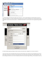
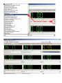
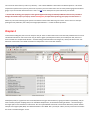
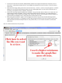
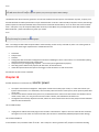
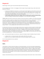
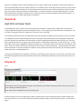
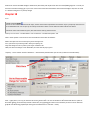
Chapter 1
For the readers - I have a life and I must tend to it, but I can sneak in every so often and contribute here. I hope others with AE
experience can chime in and help out... but this thread is needed as our trucks age and more scan tools are purchased.
***Critical edit: Powering your laptop from the cigarette lighter while using the USB-style OBDII interface has the potential to
damage the interface and/or your laptop. Contact AutoEnginuity for input before powering your laptop from the vehicle.***
I see threads where people have AutoEnginuity and other similar scan tools to look at the readings on their vehicles, but are unsure
of what to look at and what it means when they look at it. There are readings in there that can reveal stuff a tuner would rather not
share... like Fuel Injector Pulse Width, Mass Fuel Desired, and Injector Control Pressure combinations. To protect intellectual
property, I will steer clear of using AE to reverse-engineer tunes. This is for troubleshooting our vehicles: Finding and resolving
economy eviscerators, horsepower hijackers, start stealers, boost burglars, back pressure bloaters/pillagers, and sound spoilers.
Let's start with the most basic function – clearing the codes to make sure we are reading the news, not ancient history. Connection –
Key On Engine Off (KOEO):
1. Open your AE software and have your cable/adaptor connected to the OBDII port and laptop. If you have a security dongle, make
sure it is plugged in to one of the USB ports as well.
2. Click on “Vehicle” and set up your “Communications Configuration” for the software to work with our era of vehicle. There is no
way for me to cover all the versions, so I'll just post an image of how I'm set up for the quickest connection.
3. You need the key on to start a connection. Failure to have the key on will just give an error message when you try to connect, and
some versions of AE require a restart of the software to clear the error.
4. Go to “Vehicle” on the menu and select “Connect”... or just press the “F2” key on your keyboard.
5. A window will pop up, showing the progress of the connection... then the “Vehicle Selection” window will pop up. Enter your
Make, Year, and model... but I don't recommend messing with the VIN. I tried many combinations on my version of AE and it was a
wasted effort. For this exercise, under “System:” - select Enhanced Powertrain. The “OK” button can use a good clickin' right about
now.
6. Another window will pop up, asking if you want to poll all your trouble codes. I suggest “ALL” for the first connection.
You have just done the secret handshake thing and you've accessed the guts of your vehicle. Now you tread lightly until you learn
what needs to be done in here. Not only can you read sensors, but you can control many things and set up test operations. I don't
know if damage can be done, but I've never accidentally started a buzz test with the engine running... and I really don't want to try
it, nor do I suggest anybody else does.
The first screen up is the “Diagnostic Trouble Codes” screen. You will likely have a whole bunch of stuff in there from lack of
resetting – but ignore those just for now. You'll say “But all these codes!” and I say things happen over time and the list in there gets
weird without a good reset once in a while. By all means, write down all the codes (you can get descriptions from codes any other
time) because you'll want to learn your vehicle. After you've recorded your DTC list, press the “Clear” button for all codes. Now we
do an odd thing... we disconnect and repeat from step four... but don't clear the new codes that may pop up. You have just
completed your first full function with AE.
I'm writing the next step – BARO, EBP, and MAP readings with KOEO. I'll post it when completed and time permits.
Chapter 2
matt9923 - I have condensed that post to make it easier to read. Great find!!
AutoEnginuity Software Configuration When you first launch the AutoEnginuity software there are some settings that need to be
modified. The settings below are what we recommend to get the best results when connecting to Powerstroke Diesel vehicles.
Connection to other vehicles may require changes to these settings. All of these settings are located in "Communications
Configuration" on the "Vehicle" menu.
•
•
•
Computer Interface:
o Select "Auto Detect Serial Port" ONLY if you are using a Serial version of the AutoEnginuity tool
o Select "USB or Manually Set Serial Port" for USB versions of the AutoEnginuity tool
o I prefer to turn off "Automatically Connect on Launch" so I can start the software without it trying to connect
Vehicle Interface (these settings are for the BEST connectivity support for FORD POWERSTROKE TRUCKS ONLY):
o "Vehicle Interface Type" should be "J1850PWM" for a 7.3L and "Auto-Detect" for a 6.0L
o "Initialization Type" should be "Non-OBDII" when connecting to a 7.3L
NOTE: The above settings will need to be changed to "Auto-Detect" and "OBDII Compliant" if connecting to a nonPowerstroke vehicle
o "Use Fastmode CAN" and "Use Heartbeat" should not be selected when connecting to a Ford
The above settings are automatically saved. You won't need to adjust these unless you change them to connect to a
different vehicle.
Cylinder Contribution Testing (7.3L) AutoEnginuity can be used to execute Cylinder Contribution Tests (CCT) on 94-03 7.3L
Powerstroke Diesel equipped vehicles (the 6.0L PCM doesn't have this functionalilty built-in). A common cause of failed CCTs is "EOT
out of Range"...which means Engine Oil Temperature is out of range. The following approximate EOT values are required to execute
a CCT:
•
•
•
94-97 Powerstroke Diesel: 170°F+
99-03 Powerstroke Diesel: 135°F+
Also, make sure that ALL accessories are turned off (A/C, etc.)
Note: on 94-97 Powerstroke Trucks, you may be able to audibly hear the test turning cylinders on and off (trucks with newer
calibrations should complete 3 test cycles). The test will be terminated early if a cylinder is found to be very bad. Once that cylinder
is repaired, the CCT will need to be run again to check the rest of the cylinders. You will not hear this on the 99-03 Powerstroke
Trucks as the test is performed differently. There is also a potential problem with the CCT if it detects an issue with either the #6 or
#8 cylinder. Due to the fact that cylinders #6 and #8 fire in sequence and are physically adjacent to each other in the engine, it is not
uncommon for a CCT to mis-report a problem with one cylinder that actually exists in the other.
For 99-03 7.3L, another way to use AutoEnginuity to see if there are problems with a particular cylinder is to monitor the "Cylinder x
Change Rotational Vel" or "Percentage of Crank Deceleration" PID (also commonly called PERDEL). This PID exists for all 8 cylinders
and is a representation of crankshaft velocity change (decrease) at the time the cylinder is firing. Ideally, these should all read 0%.
Any cylinder consistently reading more than 3-5% change in rotational velocity is suspect and should be further examined. Note:
Engine should be fully warmed up before checking PERDEL data.
7.3L Injector "Buzz" Test The Injector "Buzz" Test can be used to look for a faulty fuel injector. It is best to run this test on a totally
cold engine, one that has sat overnight and has not been started. Initiate the "Buzz" test and then listen carefully to the injectors as
the test is completed. First, all 8 injectors will "Buzz" at the same time. Then, the IDM will "Buzz" the injectors in numerical order (1,
2, 3, 4, 5, 6, 7, 8). Remember that cylinders 1-3-5-7 are on the passenger side and 2-4-6-8 are on the drivers side, with cylinders 1 & 2
being at the front of the engine. You should hear a strong "Buzz" bouncing from side to side for all 8 injectors. If one of the injectors
doesn't "Buzz", you've found a problem cylinder. It is important to note that when an injector fails to "Buzz" properly, you will still
hear the other 7 injectors make a faint buzz...this is a designed function to protect the IDM.
Note: Because the IDM will "buzz" the other 7 injectors faintly during individual cylinder tests, it is possible for the "Buzz" test to
report no problems detected. If the "Buzz" test reports no failures, but you don't hear a particular cylinder "Buzz"...more than likely
there is a problem with that injector.
It should also be noted that an injector failing a "Buzz" test can have many causes. The injector can be in a failed state (loose
armature plate screw, bad solenoid, etc.), the UCV (under valve cover) gasket or harness could be damaged or disconnected, the
main engine harness could be damaged or the IDM could be damaged. Further inspection will be necessary to determine the actual
problem...but at least you now have a place to start.
Quick KOEO Sensor Checks: There are a few sensors that can be easily checked with a scantool. Starting with a "Dead Cold" engine
(let it sit overnight, don't start), connect to the truck with the ScanTool. Check the following:
1.
2.
Oil Temp should closely match the current Ambient Temp.
Readings for Exhaust Backpressure, Manifold Absolute Pressure and Barometric Pressure should all be within 1/2 psi of
each other (this should be true with the engine either warm or cold).
(Note: with the engine running, MAP and EBP values are "Pressure + Baro". For example, if Baro is 14.7 and there is 2psi of boost,
MAP will read 16.7. Also, there is a calculated PID called "Manifold Gauge Pressure" that doesn't have the Baro pressure added in).
KOER (Key On Engine Running) On-Demand Test: On the 7.3L, the primary purpose of this test is to check the functionalilty of the
High Pressure Oil System and the Exhaust Back Pressure Solenoid. On the 6.0L this test may return Misfire, VGT, or Glowplug codes.
7.3L Powerstroke Starting Req.:
Vehicle Power: 10.5v
RPM Signal : 100rpm
Inj. Cntrl Press. (ICP): 0.85v (about 500psi)
Fuel Pulse Width: 1 to 6 milliseconds
6.0L Powerstroke Starting Req.:
Vehicle Power : 10.5v
RPM Signal: 100rpm
Inj. Cntrl Press. (ICP): 0.85v (about 500psi)
Fuel Pulse Width : 0.5 to 2 milliseconds FICM SYNC and SYNC Achieved
*Note: the above starting requirements for both 7.3L and 6.0L Powerstroke Diesels assume the following:
•
•
•
•
•
•
Sufficient Oil Level and Pressure
Acceptable Quality Fuel
Sufficient Fuel Pressure
Sufficient Air Supply
Proper Glow Plug Operation
Proper Injection Timing (PCM Controlled)
P1298 - "IDM Failure" (7.3L)[indent]This code can be set by a low battery. Connect a battery charger, clear codes and re-run KOEO
tests. If this code doesn't return, check charging system and batteries and repair as necessary. If the code returns, IDM is suspect.
P1316 - "IDM Codes Detected" (7.3L) IDM Codes are stored in memory in the IDM itself. The P1316 DTC is an indication that there
are stored IDM Codes that need to be retrieved and/or cleared. Executing a "Clear Codes" will clear both PCM and IDM codes...DO
NOT CLEAR CODES until you have retrieved and reviewed the codes stored in the IDM! If you get a P1316 DTC, the following steps
will allow you to view the stored codes in the IDM using AutoEnginuity:
1.
2.
3.
Execute a KOEO (Key On Engine Off) Test.
Execute an Injector "Buzz" Test.
The displayed results from these tests will include any stored IDM Codes.
Please keep in mind that IDM Codes are stored in memory. If you have a code indicating a fault, but there is no drivability problem,
the fault may not currently exist. After taking note of the codes, execute a "Clear Codes". At this time you should be able to re-run
the above tests with no IDM codes generated. If one or more IDM codes are still present after the "Clear Codes" command has been
successfully executed and the above tests performed again, the fault still exists and further examination is necessary.
P1211 - "ICP Higher/Lower Than Desired" (7.3L) We all know that this code is commonly caused by "Hot Chips" that are demanding
more Pressure (ICP) than the High Pressure Oil Pump can deliver. For what it's worth, these are the exact parameters that trigger
this code:
•
•
ICP 410psi Higher Than Desired for 7 Seconds
ICP 280psi Lower Than Desired for 7 Seconds
This code can also be caused by legitimate High Pressure Oil System issues. Below is a list of some of the causes:
•
•
•
•
Failed or Sticking IPR (Injection Pressure Regulator)
Failed or Weak HPOP (High Pressure Oil Pump)
Any Leak in High Pressure Oil System (o-ring, stuck injector, etc.)
Low Fuel Pressure (Rare)
P1280 / P1281 / P1283 - (7.3L)
The above codes are related to ICP also. If the Service Engine Soon (SES) light is on and these codes are present, the ICP reading
through any scantool will not be accurate as the PCM is using a "default" ICP value. These codes are all "electrical" in nature.
Common causes are shorts between the Red and White IPR wires or between the Red wire and ground. These can also sometimes
indicate a PCM problem.
Chapter 3
Staying with the basics:
I want to start with a simple reading that is easy to overlook, but can have a profound effect on your fuel economy and performance
- the Exhaust Back Pressure sensor, Manifold Air Pressure sensor, and BARO (barometer). These three are akin to a GPS indicating
“you are here” for everything that follows, once the truck is started: It does no good to “Turn right here” if the GPS thinks you're
someplace you're not. It also does no good if your engine tuning says “Set fuel delivery to X” if the sensors are lying to the PCM.
Before we go on a clicking rampage, you first want to see the screen. Many of you have larger screens than my netbook, but just as
many are as crowded as I am. To preview if your screen can handle the whole nine bards (not a typo, just taking creative license),
click on the “Live Data Meter” tab. The screen shot below contains some inspiration as to how to make more room on the screen, if
needed:
Now I've done it... I gave away one of the secrets - you can monitor up to 9 sensors at a time. There will be a later discussion on
the practical number of meters up, but I will be keeping as few meters active as possible. This test calls for just three meters...
perfect. Using the screen shot below, you want to select one sensor for each meter, until the meters look like the second screen shot
below that.
You can see the values from my truck in my driveway... I live at about 1000 feet. These values are absolute pressure – this means
compared to a perfect vacuum, the air pressure at my home is just over 14 PSI. That's zero for a back pressure gauge and the boost
gauge, so you can see how relevant this test is. Here is a [LINK] to see what pressure you should see at your altitude.
***Critical edit: Powering your laptop from the cigarette lighter while using the USB-style OBDII interface has the potential to
damage the interface and/or your laptop. Contact AutoEnginuity for input before powering your laptop from the vehicle.***
What's my next session? Setting up the system to record these three values while we go for a drive. There's more to it than just
pushing the shiny red button, but I always encourage experimentation... it makes for better questions.
Chapter 4
I mentioned recording data, but we're not ready for that yet: There's a little-known secret in AE that really should be less of a secret:
The default maximum for each sensor sucks. Say you want to graph your backpressure after you recorded your data, the most a
stock truck will see is maybe 65 PSI absolute – and that's being pushed downhill in second gear by a heavy load. Click on the “Live
Data Grid” tab and look at the default maximum for backpressure in the screen shot of below:
40 PSI (heavy load) on a graph from zero to 344.46 (where do they get these numbers?) is going to look like a speed bump, and you
want a freeway overpass. Graphing aside, if we saw 300 PSI backpressure, we wouldn't be looking at AE data... we'd be looking at
the engine parts on the road that we coasted over. AE is set up with default maximums to fit the most wild factory vehicle. Another
example is the engine speed (RPM): The default maximum in AE is 8000. That's just silly for a diesel, so every meter we want needs a
visit to the “Live Data Configure” screen.
I set my absolute pressure maximums to 50 for this exercise, but a realistic maximum for my modified truck would be 65 on the
backpressure and 55 on the MAP. The question about alarms was asked – that's the trigger in the screen. I'm not covering it yet, but
that's another toy for you to experiment with before I get there. If you get playful, you can set a MAP limit on a stock truck to 30 PSI
absolute... then it will play an audio file that cries out “Cap'n! I don'-a think she'll take much more!” (which you have to acquire on
your own). I digress... here is the screen shot with the maximums set to be reasonable.
We went through all this trouble to select the sensor and set the maximums for good graphing, now we don't want the software to
set everything back to default when we disconnect – so we save the session. Click "Vehicle” on the menu, then “Save Session”. Give
it a name you can remember – like “Tugly's class” (I have a chance here to be immortalized and I don't want to pass it up). The file
name Exh-Boost would probably work better.
The next time you connect to to the vehicle, you can start a new session, or you can load a prepared one like the Exh-Boost you just
made. Here are some saved sessions I have on file:
Well... that's it, now we need to start recording and start an engine. Record first, get 10 seconds of data, then start up and go for a
drive. If you get a chance to get a WOT session, all the better.
Word of warning: I learned the hard way that if you change a parameter while in record, the recording will stop instantly. Once you
are set up and recording, you are committed to that meter set until the next recording session. While recording, you can hit pause at
any time and start back up by hitting the pause button. There is a stop button as well, which will complete that recording file. If you
hit stop and want to record more, you need to start a new file. If you allow the software to auto-name the recording files, it will just
name it for the vehicle, model year, and today's date. If you record twice in one day, it will delete your first recording... unless you
give the second recording a different name than the first one.
Obviously, working with filenames and meter parameters is not to be done while driving... though some have tried.
urge you to leave the computing time to the side of the road, or have an assistant tend to it.
I strongly
What's next, you say? We're going to look at your data... might I suggest you record some? "Oh my gawd! This has
homework!?!"
Chapter 5
More AE basics: Playing back a file you recorded.
I'll do just one sensor, so you get the idea... then you can practice with one or more sensors that you have recorded while tinkering
with AE. I used BARO because it points out a few important things:
•
•
•
•
Not all sensors need the same attention, BARO probably needs the least. Engine Oil Temperature is important, but it's a
slow mover... unlike Injector Control Pressure. I set my BARO to be looked at once every 5 seconds... I'll show you how to
do that later.
With these slow changes, looking at the sensor over the time of say... a minute... you'll see a very boring flat line. I recorded
BARO over a very long time while changing altitude and I got a useable graph where I can see what my elevation was as I
was driving. The importance of this is again for a later lesson.
Some sensors have huge ranges during operation, like RPMs... they go from 600 at idle, to 3200 or so on a stock truck. The
default setting for RPM in AE is 8000... silly for a diesel and the graphing will look a little flat. I set my RPM maximum at
3500. The BARO is a sensor that has tiny changes, so the "scaling" has to be tiny, if you are going to see these changes on a
graph. Default max for BARO is 5 volts - perfect, because sea level is about 4.7 volts.
When playing back my BARO on a graph, I want the biggest rise and fall I can get to make the altitude change obvious
(without going off the graph), so I changed the minimum. Why change the minimum? Zero volts is a perfect vacuum and I
didn't dock withe the International Space Station on this particular drive, so I set a realistic minimum for the altitudes I
experienced.
Here are a few thousand words on the procedure.
This is what happens when you look too closely at a slow-moving sensor. Very boring:
I skipped over a few things that may or may not be obvious to Scan Tool users. In the event the above is a bit confusing, I'm pausing
for questions.
Chapter 6
I will be using akaFrankCastle's data to point a few things out. I have attached the "modified" data that anybody with AE can open
up and follow along. Download the file and right-click on it, then select "Rename". Where the file name says DOC, change that part
to CSV.
Since this has so much data, it will try to "play" the data out in real time upon loading. It will take a long time to load, so you want to
move the "Playback Speed" slider all the way to the right in order to fast-forward. After the whole file has loaded, the graph will
display everything that will fit in the time limit of the AE software. This data recording is just short enough to fit this file on one
screen. Remember, these pressures are "absolute", so that means they are the atmospheric pressure at your altitude PLUS the
pressures built up in the engine at that moment. Here are some notes on the raw data I received:
I cleaned up the error and we have this:
I then made my AE screen bigger to see more detail and zoomed in on the first spike on the graph:
You can see how the backpressure (EPB plus EBP KOEO reading) stretches above the MAP (boost plus the MAP KOEO reading) when
we get on our trucks. We lose efficiency in the stock turbo at higher pressures and this is a normal result. Doing the math:
•
EBP (absolute) peak is 38, but we subtract the EBP KOEO of 12 to get the real ehaust backpressure of 26 PSI.
•
MAP (absolute) peak is 29, but we subtract the MAP KOEO of (roughly) 12 to get the real MAP (boost) of 17 PSI.
This looks to be textbook for a healthy stock truck (Wicked Wheel notwithstanding), until I find data that says otherwise. Of course,
we have no other data like speed or RPM to see how the truck is reacting to this powah... but I wanted to keep this very basic to give
everybody a chance to absorb the information.
Now I'm watching for somebody to raise their hand for a question.
Chapter 7
Why during the closeup of the wot run...are there more spikes than gears?
The RPM data wasn't in the file, but I can estimate.
The thing to note is how the backpressure builds higher as the load increases (wind load, higher gearing, and speed)... this is the
breeding ground of high EGTs.
EBPV sticking? I'll look for another example of EBP/MAP data from a stock truck at WOT. I should have some here.
Chapter 8
Here's an experiment: I have some other data from a truck that isn't faring so well (assuming the data is from a WOT run). I set the
MAP and EBP minimum pressure readings to match the pressure for the altitude. This gives me a graph that only shows boosted
exhaust and intake pressures. This data has RPM so you can see what your engines do:
When I compare this with the data from before, it's easy to spot the "Ham Sammitch" factor and the "Where's the Beef?" syndrome.
Neither set has Bacon/Permagrin, because we're dealing with stock. Note how higher EPB doesn't translate to exactly the same
boost rise on the MAP side... that's stock turbo efficiency.
So... with a stock truck, it's not unusual to see about 1 PSI difference between exhaust and intake at cruise speed, and about 6-9 PSI
difference at WOT. That's about what I saw on Stinky when he had stock hardware with a tuner... but the numbers were taller. I
would get about 36 PSI indicated backpressure and... oh... 28 PSI indicated boost at the MAP (30 on the hot side of the intercooler).
There are a lot of variables, like altitude, temperature (combined makes air density), condition of the truck, air filter, exhaust
configuration, blah-dee-blah-blah....
If you are looking at your truck with a scan tool, expect 1-3 PSI differential between EPB and MAP while driving "sanely". You'll see
between 6 - 9 or even 10 PSI differential at high load... like WOT at high speed, pulling a grade, a headwind, or trying to break
something at a tractor pull. If your EBPV is on because of a decel tune, expect really big pounds for backpressure readings (upwards
of 40 PSI indicated) and bupkis for boost (like 1 or 2 PSI indicated).
If everybody's had enough of the EPB/MAP/BARO already, I'd like to know what you'd like to learn next. No-starts? Anemic
performance? How to gauge MPG improvements with AE... instead of waiting for an empty tank? Tire size (ties in with MPG)?
Chapter 9
Starting
You are now about to learn what I was referring to when I mentioned "data sampling rate" when comparing AE to Infinity. With just
the 5 PIDs I set up, AE recorded each one once per second. That's 200 milliseconds for each PID, for a total of 1000 milliseconds (1
second) to read them all before it came back to the first PID. It took me 1.5 seconds to start the truck (about 40 degrees, not plugged
in). Any guesses how much data I got while it was cranking?
Anyway... I won't repeat all the steps to set up a recording session, but I will show you my playback options... which specifies exactly
what I recorded to monitor the starting condition of the truck. I threw IPR in the list, so you can see the lag between what the PCM
wants and when it gets it... like nooky. One piece not in there directly (like voltage) or indirectly (like glowplugs revealing themselves
with a voltage drop): Fuel Pressure. I have a gauge, so fuel pressure is 62 PSI. I did not play out my pulsewidth over time because I
won't show combined ICP and FIPW trends on the forum from this tuner.
I'm just posting screenshots and my notes with no other explanation. If I missed some detail or you want to know more in depth,
please say/ask something.
Chapter 10
So I was getting ready to show how the Injector Pressure Regulator compensates for the drop in RPMs, in order to keep the Injector
Control Pressure up with a slower-moving High Pressure Oil Pump. Simply put, the pump slows down and and the valve has to be
opened more to keep the oil delivery going at the same flow.
When I zoomed in on the graph, I spotted something I would not otherwise have noticed: I can see the effects of the multiweight oil
warming up. The RPMs are constant and the oil pressure is dropping, which I expect because warm engines have a lower Injector
Control Pressure. What I didn't expect is the regulator (oil pressure valve) is opening more instead of closing more, to keep the oil
pressure (ICP) from falling even faster. The effects of a heavier oil weight is the only changing factor I can think of that would cause
this.
So... show of dazed eyes: How many did I lose on that one?
Anyway, here's the significance of all of this: The Low Pressure Oil Pump (LPOP) sends oil up to the High Pressure Oil Pump (HPOP).
The HPOP is always the main focus because this powers the injector. The injector gets an electrical signal to be sure (Fuel Injector
Pulse Width or FIPW), but that just lets the oil in to squeeze the fuel out of the injector with great force. The higher the ICP, the
better the atomization (finer fuel mist) and the faster the fuel squeezes out of the injector (quicker injection means more power and
lower EGTs).
We don't need a lot of ICP at idle and cruise, that would make the fuel hard to control at such low power demand... and more ICP is
just plain loud. When we first start, the engine is cold, the fuel is cold, the oil is cold... so we need a bump in ICP to get better
atomization when cold. As the engine warms and the fuel burns easier, we back off the ICP by about 200-300 PSI.
Now... 15-40 vs. 5-40. My little discovery demonstrates exactly why lower-weight oil works better when cold: Everything moves
easier with less effort. Most of you already know this, but now we can actually see it in the performance of the engine.
Chapter 11
I slept on it and I now have a better grasp of what needs to be done.... the basics. I got ahead of myself, sorry.
Let's start with the injector, because everything in starting is all about getting fuel into the cylinders. Once we have rotation (the
starter doing its part) and compression (the engine doing its part), we just need some fuel please, thankyouverymuch (at the right
timing). Think of it as a frat party... waiting for beer. As soon as the beer shows up, 8 lunkheads make a racket. If nobody gets beer,
no party. If only some of them get beer, there's a fight, which involves a lot of bucking and kicking. If the tap on the keg just dribbles,
the party stalls.
In order to get those pesky HEUI injectors to cough up some “beer”, we need:
•
•
•
High oil pressure in the top half of the injector (pump up the tap)
Fuel in the bottom half of the injector (beer in tap)
An electrical signal to the solenoid on the very top of the injector. (thumb on the tap lever)
HPOP, ICP, IPR, LPOP, EOT, EOP.... You'd swear this is where Campbell's got the idea for Alphabet Soup... or so it would seem. What's
up with all the acronyms and sensors with the letter O in it? Oil that is. Black gold. Texas tea. My plagiarism of a 60's sitcom
notwithstanding, this is the big time folks. All this focus on oil is not overkill. We need to pare all of this down so we have a
manageable dialog, not a lengthy class on technobabble. Focus on one thing – ICP (Injector Control Pressure). All that other crap...
those are just parts of the puzzle to get ICP. Injector Control Pressure (ICP) – drum that in. That is the high oil pressure we need in
the top half of the injector to make it say “Pssst.”
Believe it or not, fuel pressure is not so critical for firing... but enough fuel flow to refill each injector before it gets fired again is
paramount. The closest we can get to seeing if there's enough flow is to look at the pressure, so the pressure gauge is a proxy for a
flow gauge. Think about it, if a specific pressure value was so critical (on this truck), where's the fuel pressure sensor? Do you think
they just overlooked it... after they went into convulsions on sensors for the oil? You're probably thinking “The fuel part of the truck
must have been engineered in a different department and those guys are idiots.” Well... while this has some merit, the fuel system is
pretty basic: If you hear the pump and you know there's fuel in the tank, there is a good chance fuel is OK... but there are plenty of
banana peels under our feet on this one. Problems that arise here are likelier due to the age of the truck more than anything else.
Hence... the add-on fuel pressure gauge.
The electrical signal to the injector is a two-stage process. The Powertrain Control Module (PCM) is the brains of the operation, but
the Injector Driver Module (IDM) is the a55 (you know... the donkey-looking horse). Ta-daaah. What goes on inside the PCM is ubercomplex, but we have zero need to understand it for the purpose of starting the truck. We just need the appropriate sensors to tell
the PCM it's party time, the PCM then needs to grab the ol' whip and crack the a55, the a55 then needs to get off same... and start
haulin' same.
I mentioned sensors need to tell the PCM that the keg and the lunkheads are are ready before it's party time. What sensors? What
are they supposed to say to the PCM? Before we get into that, we need:
•
•
•
•
•
•
Sufficient oil level and pressure (the low oil pressure on the dash gauge)
Acceptable quality fuel
Sufficient fuel pressure
Sufficient air supply
Proper glow plug operation (on a cold truck)
Proper injector timing (PCM controlled with input from Cam Position Sensor – CPS)
Now... for the AE data that will tell us the 7.3L should start:
1.
2.
3.
4.
Vehicle Power: At least 10.5 volts with glow plugs on (but that low number is marginal... I have at least 11.5 on my truck)
RPM Signal: 100 RPM minimum (from the CPS)
Injector Control Pressure (that ICP you burned into your thinking... like pumping up the keg tap): 500 PSI, or about 0.85
volts on the ICP sensor
Fuel Injector Pulse Width (FIPW): Between 1 and 6 milliseconds (0.001 to 0.006 seconds) on the 7.3L .........Between 0.5 ms
and 2 ms (with FICM SYNC and SYNC achieved) on the 6.0L
I'm going to be mean and introduce something not in the official list: IPR (Injector control Pressure Regulator). On AE, it's called
Injector Control Pressure Duty Cycle. This is a “valve” that controls the ICP, so it's frequently helpful to know that the ICP is
responding to its commands... not just throwing a number at us for the helluvit. IPR will start in about 10% and climb while cranking,
then drop to back down when running. The number the IPR settles on is about 11%-12% on a properly-working stock truck with a
stock tune at full oil temperature (at idle). It should be very stable at idle.
Chapter 12
Three No-Starts
I have some graphs here of trucks cranking but not starting. I put color-coded arrows at the minimums needed for each sensor
reading. They all have different problems... two are easy and one is difficult.
Quote:
Originally Posted by CampSpringsJohn
If the IDM doesn't have the voltage to fire the injectors, will you still get a pulse width reading?
The IDM takes the vehicle 12V and "generates" the 115 volts needed to fire the injectors. If the IDM has no power, I'm pretty sure
the PCM will freak out and flop around like a carp on the beach when it can't B.S. with his buddy. If the power is there, but the highpower outputs are toasted, the IDM will whine and snivel to the PCM and the PCM will say "Fine. You don't have to fire the damn
sticks." and report a very narrow pulse width (under minimum) on the OBDII. This just happened this week. What blew the IDM?
Both UVCHs bad... power had nowhere to go but up in smoke.
Quote:
Originally Posted by Richard Eckerle
is marginal voltage the problem on the last graph?
Naw... low voltage wouldn't allow the pulse width to climb. Basically, the last one says it should run, but it's not running. Now we
need to visit all the other engine requirements to troubleshoot this one.
•
•
•
•
•
•
•
Good fuel?
Fuel pressure?
Good air?
Timing (CPS)? We see the CPS working because we have an RPM signal. There's a DP in there, so I recommended yanking
that long enough to get the truck running again.
Compression? It just had glowplugs replaced... unsure if they were tighteed down properly.
Glow Plug system? GPR recently replaced, GP LED works, all GPS ohmed out.
UVCH? All injectors ohmed out. Open circuits trigger a code and there is no code on the truck.
No resolution yet, but we have a checklist.
Chapter 13
A fellow member has an issue with very
•
•
•
anemic power.
The Injector control Pressure Regulator - IPR (Injector Control Pressure Duty Cycle on AE) is a "valve" that controls your
Injector Control Pressure - ICP. Remember, the ICP is what pushes the fuel out of the injector, like air pressure pushes beer
out of a keg.
The ICP sensor tells the PCM what the pressure is, the PCM takes all the other sensor data and the tune decides if the ICP
needs to raise, lower, or or stay pat. Once the tune makes a decision, the PCM tells the IPR what to do.
The High Pressure Oil Pump responds to the IPR, and the ICP sensor measures the ICP from the pump to tell the PCM what
effect the IPR command had.
This is a feedback loop.
•
Unplug the ICP cable and the stock program sets the IPR to a level where it "expects" the ICP to reach 700 PSI. This allows
the engine to run in the event of an ICP sensor failure, but the sauce is substantially subdued (low power when driving).
This is without feedback.
In this member's case, his IPR was under 5% at idle... this is really low. I don't it get below 10%, except on tuned trucks with big
nozzles... but I've never seen it this low and this is a stock truck. Why would the IPR be so low? I asked him to unplug, then plug in
the ICP sensor and I attached the resulting graph so you could take a look at what's going on:
Quote:
Originally Posted by Christof13T
Ipr perhaps getting sticky... ?
Or a failing oring that catches pressure again after it has its little fit?
I strongly suspect the ICP is lying. Remember - low power. If the IPR was sticking, the truck would be loud as hell and the throttle
would be so touchy that the truck would freak out just showing a photo of a foot at the throttle. If the IPR is working properly and
the ICP sensor kicks in with that - bad ICP... or another alternative: Something could be up with a ground connection somewhere,
making the ICP a liar again. More tests are needed before the Buck$Zooka gets dusted off.
Quote:
Originally Posted by BWST
Rich, you said you had him unplug the ICP and then plug in. Is the "what happened" circle where he plugged in again? but the throttle
starts coming up, then he plugs it in - that's probably not right. Where's the plug back in part on the graph?
The flat part of the ICP line (700 PSI) is what you would see with an unplugged ICP sensor. I'm lost as to why the real ICP signal chose
that moment to pop onto the graph... maybe one person was operating the throttle and the other plugging in the sensor. This was
all done in neutral in the driveway, we were focusing on the TPS because it did something weird on the road.
Chapter 14
While listening to crickets, I got it into my head I didn't explain that all the way through.
First, we're pulling a sensor connector... then plugging it in with the engine running. We might be seeing a "delay" before the ICP
signal pops on the graph.
1.
2.
The PCM had no feedback from the ICP sensor, so it set the Injector Pressure Regulator to about 14% at idle. Under normal
circumstances on a stock truck, this will put the idle ICP at 700 PSI. (startup is about 2400 ICP, so don't freak when it does
this) To explain what's happening, let's say you're reaching for a bottle of water by the night stand... but the lights are out.
You know where the bottle should be, so that's where you're grabbing.
The PCM is happy to blindly keep that IPR at 14%, until the ICP sensor is plugged in. Plug in ICP sensor, PCM sees the ICP,
and the PCM adjusts the IPR to fine-tune the ICP. Plugging in the sensor with the engine running is like turning on the lights
while you're reaching for the bottle of water on the night stand... you can now fine-tune your targeting.
However! When the ICP sensor came online in this instance, the ICP sensor said the ICP is 1000 PSI, not the 700 the PCM expected.
One could say "Oh look, my pressure is too high" and that's exactly what the PCM said to itself as it lowered the IPR to compensate.
The driver is complaining of weak throttle response and too much ICP won't cause that... but turning the pressure
down below normal WILL. This suggests the PCM was guessing correctlywhile the ICP was unplugged, but the PCM is going the
wrong way now... based on the feedback from the ICP (which appears to be lying). The ICP did the equivalent of putting a series of
mirrors in front of your bottle of water before turning on the light. You now see the bottle in a different location than where you
though it should be... so you're grabbing wildly and your efforts will never satisfy your thirst.
For those with a scan tool, do you want to know right now today if you have a good ICP? A cold stock engine runs ICP about 700 PSI
at idle, and it slowly drops until it reaches about 480 PSI at idle when warm. Unplug the ICP connector with a warm truck running
while you watch ICP and IPR (ICP Duty Cycle). On a stock truck - if plugging in the ICP shows about 700 PSI and the IPR starts to
gently change that number to about 480 PSI and an IPR about 11.3%... all good. If plugging in the ICP shows a radically different
number than 700 PSI (I'll get a solid number later) and the IPR makes a dramatic change to correct the pressure, don't load a money
clip into the Buck$Zooka just yet... this warrants more investigation.
Man... I just read the post above again and I realize this is a tough one to simplify, yet explain it completely. Paring it to the bone:
1.
2.
Unplug ICP sensor on a running warm engine and AE says IPR is about 14%, with ICP 700 PSI.
Plug ICP sensor back in and IPR should drop to about 11% and ICP about 480 PSI at idle on a stock truck.
If you see anything different than that, ask questions.
Chapter 15
MPG
I mentioned this in an obscure thread and I thought it was worth mentioning here. I have seen a few members with OBDII devices
that monitor the truck as they drive and I noticed they focus on things like transmission temp, ICP, and FIPW. If you have the ability
to monitor just two items on a scan gauge, transmission temp is a good one, to be sure... but there is a "biggy" in there that gets
overlooked: Mass Fuel Desired (MFD). This is the PCMs interpretation of exactly how much fuel you need to get the job done (even
with cruise control active) at any given moment. By itself, the number is pretty fickle... but couple it with your speed, gear, and
situation and you have an MPG meter. If you are cruising at a set speed in OD on the flat with no wind, you can memorize that
number for future reference.
Example: I drive at 65 MPH every day on the same stretch of road, and I have plenty of flat stretches of road. I'm custom-tuned with
big sticks, so my MFD isn't likely to match everybody else's, but I know my MFD number at 65 MPH on the flat with no wind. Say I
have a hypothetical MFD of 22. If the number climbs to 24 in a headwind, I know I've lost about 10% fuel economy on that stretch of
road. If I tow, that number will climb and I can see what kind of hit I'll take at the pump... before the gauge has a chance to move!
Say you do a mod or repair after you know your MFD number... you'll know the effect on your MPG right freaking now - not 300,
400, or 500 miles later. Remember: The gear you're in, speed, wind, hills, and other loads change the meaning of the number - so
you need to compare the number under identical circumstances.
Chapter 16
High EGTs and lower boost.
As everybody knows, there are many causes of this and the first assumption is usually a boost or exhaust leak. AE can be used
to help troubleshoot this problem, but like everything else with AE... it's not going to just tell you "Well there's your problem!". You
now need to investigate the why of a reading. Here's a scenario I just went through:
I was climbing a mountain pass, like I have done many times before. My EGTs were higher than they usually are on the same grade,
so I immediately went into troubleshooting mode. My AE was showing a lower Exhaust Back Pressure reading than I expected by
about 10%. My boost was down about the same amount. One person might grab the boost leak detector and have at it, after they
went crawling under and over the engine on sound and soot safari. I started with the simple stuff... the filter minder. Yup... it's time.
Some might say "But Tugly, a clogged filter should raise backpressure.". Nope. Block a shop vac hose with your hand and listen to the
motor... it spins up! There is more vacuum, meaning the air in the turbine is a much lower density... reducing the load on the motor.
Put that same theory on our beast and there is less density on the compressor side of the turbo (vacuum), so the exhaust pushes the
turbine more easily... reducing backpressure.
It's easy to get intimidated by the complexity of our beasts, I've been guilty of that many times. As I learn more, many woes on the
forum keep coming back to the first thing I learned in a diesel class I attended at the dealership: Plenty of clean fuel, clean oil, and
clean air.
Chapter 17
Quote:
Originally Posted by BWST
I see the EBP sensor is still reading almost 2psi high. I had cleaned the sensor and tube, both full of carbon. Guess the sensor did not
recover. Should I go ahead and replace it?
Is there a way to have the BARO show up in psi instead of volts?
It needs replacement only if that reading above is KOEO. That differential is equal to the driving pressure of about 45 MPH on the
flat at your altitude. It's not a rush, but I would replace it before towing or hauling. That 2 PSI isn't the scary part... the fact that it's
lying is.
AE does not convert the BARO voltage to absolute PSI, but Infinity and maybe a few other scan tools/OBDII gauges do. I can tell you
that's the same Baro reading I got in your area. I had a chart around here somewhere that converted voltage to PSI, but I can't find
it. I did find a little gem in my search, though.
Chapter 18
Quote:
Originally Posted by BWST
Question: Is there a KOEO test that checks relays, sensors and such and reports back? All I've done so far is just pull up nine meters on
the Live Data Meter tab. I've set up a Cyl rot velocity session and a "basic" session with nine meters like the ones above.
What do the colors mean? Most are green, but some meters come up yellow and red.
Look up. You are on the "Live Data Meter" tab. You want the "Test Onboard System" tab.
Colors: Great question. From the Scan Tool User Guide that came with the software:
Meters will report the current status of the sensor through color
cues. If the sensor is functioning at 80 - 90% of its capacity, the
meter will change its color to yellow. If the sensor is between 90 100%, the meter will change to red. Below 80%, the meter will dis-play in green.
"Capacity" - This is another word for "Maximum"... determined by the Max Value you set here (in relation to the Min Value):
Now... to play with it, let's say you want the IPR to turn yellow at 30%. You can set the Max to 38% and the IPR will turn yellow at
about 30% (getting on the throttle) and red at about 34 %, but graphing gets a little more involved if you want to see an IPR value
graphed over 38% during playback (the value gets recorded even if it's over Max... I think).