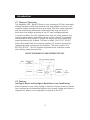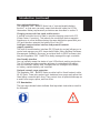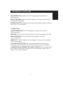
1
UK
En
UPS
Uninterruptible Power Supply
FOR MODELS:
F6C700-EUR/F6C1000-EUR/F6C1400-EUR
User Manual
P73335
Language Table of Contents
UK
En
English . . . . . . . . . . . . . . . . . . . . . . . . . . . . . . . . . . . . . . . . . . . . 1
Table of Contents
Section
Page
1.
Safety Instructions ..........................................................................1
2.
Introduction ....................................................................................3
3.
Installation ......................................................................................9
4.
Operation......................................................................................11
5.
Maintenance..................................................................................16
6.
Replacing Battery..........................................................................16
7.
Troubleshooting ............................................................................19
8.
Communication Interface..............................................................21
9.
Specifications ................................................................................24
10. Appendix A: Typical Run Time......................................................26
1. Important Safety Instructions
En
1-2 TUV Safety Instruction
• Please observe the following precautions to ensure personnel safety and
reliable equipment observation:
• The sound pressure level at the operator’s position according to IEC
704-1:1982 is equal or less than 70dB(A).
For installation:
• The unit should be installed by service personnel only.
• Upon installation, it should be ensured that the sum of leakage current
of the UPS and the connected consumer does not exceed 3.5mA.
• The socket outlet should be located near the equipment and
easy to access.
Other safety instructions:
• The UPS contains voltages which are potentially hazardous. All repairs
should be performed by qualified service personal. The UPS has its own
internal energy source (battery). The output receptacles may be alive even
when the UPS is not connected to the mains.
• When replacing batteries, always use the same type and quantity as the
previous one. Batteries of GP1270-F2(CSB 12V/7AH*2) for 450VA and
700VA; GP12110-F2(CSB 12V/11AH*2) for 1000VA, and GP12170-B1
(CSB 12V/17AH*2) for 1400VA models.
• Do not dispose the battery or batteries in fire as this may explode.
• Do not open or mutilate the battery or batteries as released electrolyte
is toxic and harmful to skin and eyes.
• A battery can present a risk of electric shock and high short circuit current.
The following precaution should be observed when working on batteries.
• Remove watches, rings, or other metal objects.
• Use tools with insulated handles.
• The equipment is to be operated by fully trained personnel.
1
Safety Instructions (continued)
EC Conformity Declaration
The devices comply with the regulations of the following guidelines:
• 73/23/EEC guideline of the Council for approximation of the legal
regulations of the EC countries concerning the electrical apparatus within
certain voltage tolerances, modified by the guide-line RL 93/68/EEC of
the Council.
• 89/336/EEC guideline of the Council for approximation of the legal
regulations of the EC countries concerning the electromagnetic
compatibility, modified by the guide-lines RL 91/236/EEC and 93/68/EEC
of the Council.
The compliance with the following standards provides the conformity:
EN 50091-1-1
EN 55022, class B
2
2. Introduction
En
1-3 SYMBOLS
PROTECTIVE GROUNDING TERMINAL: A terminal that must be
connected to earth ground prior to making any other connection
to the equipment.
A terminal to which or from which an alternating (sine wave)
current or voltage may be applied or supplied.
A terminal to which or from which a direct current or voltage may
be applied or supplied.
This symbol indicates the word "phase".
This symbol indicates the principal on/off switch is in the
ON position.
This symbol indicates the principal on/off switch is in the
OFF position.
May be used in lieu of the wording "Caution Risk of Electric
Shock" for any cautionary marking.
3
Introduction
2-1 Theory of Operation
The Regulator PRO™ NetUPS Series is a line-interactive UPS with Automatic
Voltage Regulation (AVR) that provides clean and reliable AC power to the
computer system through the input and output EMI filter, surge suppressor
and line-conditioning transformer (autotransformer) that can boost or
buck-down line voltage according to the AC input voltage amplitude.
In normal condition, the UPS supplies power from the utility power to the
load (computer system, workstation, server or other device). The bilateral
converter works as a charger to charge the battery and at the same time
keeps the battery fully charged. This term is called "ON UTILITY MODE".
When utility power fails, the converter supplies AC power to the load by
transferring power coming from the batteries. This term is called "ON
BATTERY MODE". The UPS supplies regulated power, shutdown results
when battery power becomes low.
BLOCK DIAGRAM OF LINE INTERACTIVE UPS
AVR: Auto Voltage Regulator
Utility
EMI filter &
Surge
Suppressor
BATTERY
EMI filter &
Surge
Suppressor
Bi-lateral
converter
AC
OUTPUT
2-2 Features
Intelligent Boost and Intelligent Buck-Down Line-Conditioning
When brownout or over utility voltage is detected, the boost and buck-down
line-conditioning will automatically adjust the incoming voltage and deliver a
regulated AC power to the equipment connected to the UPS.
4
Introduction (continued)
User replaceable battery
The Regulator PRO™ NetUPS Series has a "user-replaceable battery
function" so that users can easily swap the batteries inside the UPS by
themselves. Battery replacement procedures are described in section 6.
Charging current with low ripple and harmonics
A special controlled circuit is used to provide charging current with PFC
(Power Factor Correction). This reduces the conducted electro-magnetic
interference to other facilities sharing the same distribution panel with your
UPS and therefore extends the battery life of the UPS.
Intelligent communication interface and powerful network
support capability
The built-in communication interface (RS-232 and dry contact) allows you to
control and manage your UPS via powerful Belkin Sentry Bulldog Shutdown
Management Software. Moreover, an optional built-in SNMP accessory slot
lets your Regulator PRO™ NetUPS be easily managed through a network.
User-friendly interface
You can instantly assess the status of your UPS without pushing any button.
The LED display provides complete and easy to understand information,
such as load level, battery level, intelligent boost, intelligent buck-down,
on battery, replace battery, and overload.
Optional network surge protection
The Regulator PRO™ NetUPS Series provides built-in Novell network cable
(RJ-45) jacks. These jacks protect your hardware from surges and spikes that
travel along communication lines. They protect from all potential damage as
a result from surges, spikes, and line-noise.
2-3 Annotation
The two signs shown below indicate that important instructions need to
be followed:
5
En
Introduction (continued)
2-4 Front Panel
ON-TEST
OFF
ON BATTERY
BUCK
NORMAL
BOOST
OVERLOAD
REPLACE BATTERY
LOAD LEVEL
BATTERY LEVEL
ON/TEST: Pressing the button activates two functions. One is ON,
the other is TEST.
*ON: Pressing the button on the UPS and power the load.
*TEST: To activate UPS self-test. It can verify both the operation of the UPS
and the condition of the battery.
OFF: To turn off the UPS.
BUCK-DOWN LED: Indicates the UPS is correcting high utility voltage and
offering a normal voltage to the load.
NORMAL LED: Indicates the UPS is supplying utility power to the load
without affecting the utility power condition.
BOOST LED: Indicates the UPS is correcting low utility voltage and offering a
normal voltage to the load.
OVERLOAD LED: Indicates the UPS exceeds the acceptable rated capacity of
the UPS.
LOAD LEVEL LED: Displays the percentage of the loads (20%, 40%, 60%,
and 80%) connected to the UPS.
6
Introduction (continued)
ON BATTERY LED: Indicates the UPS is supplying the load from the
battery power.
REPLACE BATTERY: Indicates the UPS battery is no longer useful and must
be replaced immediately.
BATTERY LEVEL LED: Displays the remaining percentage of battery capacity
(25%, 50%, 75%, and 100%).
2-5 Rear Panel
OUTPUT RECEPTACLES: The UPS supplies AC power to the load via
these receptacles.
BREAKER: This is used to prevent high-input current from reaching the UPS.
INPUT RECEPTACLE: AC input utility power supplies to the UPS
via the receptacle.
SNMP SLOT: A SNMP adapter can be plugged into this port for managing
UPS on the network.
TVSS SURGE PROTECTOR: This connector is used for protecting the
transmission line of the Ethernet card from surges, line-noise, and spikes.
COMMUNICATION INTERFACE (RS-232/DRY CONTACT): The communication
port is used to allow the PC and the UPS to communicate. Please refer to
section 8 for more information.
7
En
Introduction (continued)
Rear panel of F6C700-EUR
Rear panel of F6C1000-EUR/F6C1400-EUR
8
En
3. Installation
3-1 Unpacking
• Please read this user manual before installing the UPS.
• This UPS contains batteries that are potentially hazardous to the user,
even when the UPS is not connected to the utility power.
• All repairs should be performed by qualified service personnel.
• Before unpacking the UPS, check the packing box. If there is any visible
damage, contact your dealer at once.
3-2 Before Installation
• Avoid exposing the UPS to direct sunlight or other heat source.
The UPS should be facing away from direct sunlight glare.
• Choose a well-ventilated area to position your UPS to allow adequate
dissipation of heat.
• Ensure that the UPS surrounding area is clean and free from moisture.
• Do not put heavy objects on the cable or power cord.
3-3 Installation
1. Connecting to utility power
Belkin Sentry Bulldog Shutdown Management Software and RS232
cables can be used with this UPS. To use, connect the interface cable
to the computer interface port on the back panel of the UPS and
then connect the cable to the serial port on your PC.
F6C700-EUR
F6C1000-EUR/F6C1400-EUR
9
Installation (continued)
2. Charging the battery
The battery charger of the UPS automatically charges the battery
whenever the power cord of the UPS is connected to a normal
utility power.
When the UPS is running for the first time, charge the UPS for
at least six hours to ensure batteries inside are fully charged
before operation.
You may immediately use the UPS without having to wait for the
batteries to be fully charged. However, it is advisable not to do this
as the UPS will have a shorter back-up time than expected if such
action is taken.
3. Connecting the load
Calculate the power consumption of your loads to ensure that an
overload condition will not happen.
Plug the equipment into the output receptacles on the rear
panel of the UPS.
Turn on the equipment connected to the UPS.
Caution: Do not connect a laser printer to the UPS.
4. Connecting the RS-232/DRY CONTACT
Connect the interface signal cable between the RS-232/DRY Contact
port on the rear panel of UPS and COM1 or COM2 of the computer
if necessary.
The DB-9 connector can work as a dry contact or RS-232
communication port depending on the type of cable and software
used. Refer to section 8 of the communication interface for
more information.
10
En
4. Operation
En
4-1 Cold Start when utility is not present
Even with the absence of utility power, the UPS can be turned "On".
Just push the ON/TEST button and wait for about two seconds for the
UPS to be turned "On". The INVERTER LED will light followed by a
beep and the UPS is "On".
4-2 Turning 'ON' the UPS
Under normal utility power, push the ON/TEST button for the UPS to be
turned "On". Once the UPS is "On", it will emit a beep and then supply
power to the loads.
4-3 Turning 'OFF' the UPS
Pressing the "Off" button will immediately stop the UPS from supplying
power to loads.
Note: It is possible that the utility power is still present even though
the OFF button has been pressed. To fully turn OFF the UPS, it is
advisable to unplug the power cord.
4-4 UPS Self-Test
Pressing the ON/TEST button when the UPS is in "ON UTILITY MODE"
will make the UPS shift to "ON BATTERY MODE" and automatically
perform a self-test for about 10 seconds. After the self-test, the UPS will
return to "ON UTILITY MODE".
4-5 Silence Function
The buzzer can be turned "On" or "Off" by toggling the ON/TEST
button when the UPS is in "ON BATTERY MODE".
11
Operation (continued)
4-6 Load Level Display
The 4-LED load percentage display shows the power level (20%, 40%,
60%, 80%) drawn by the loads from the UPS. If the UPS is overloaded,
the OVERLOAD LED will light.
4-7 Battery Level Display
This display shows the battery capacity left in the battery. The level is
represented by percentages of 25, 50, 75, and 100. These LED will
extinguish gradually when using battery power. When battery capacity
reaches the minimal level of 25%, the lowest LED (25%) blinks and there
is an immediate need to charge the battery. Under this condition, the
battery can only supply less than five minutes of run time for the load.
4-8 If certain abnormal conditions occur, the UPS will send the
following messages:
ON BATTERY MODE: When the UPS is in ON BATTERY MODE, the ON
BATTERY LED will light, preceded by a beep every two seconds, and
then the UPS will start supplying power to the load through the battery.
12
Operation (continued)
OVERLOAD:
If an overload occurs, the OVERLOAD LED will light and a continuous
beep will be heard. Under this condition, check the load connected to
the UPS.
BUCK/BOOST:
If the UPS encounters a high utility voltage, the function of the
buck is to automatically curtail this voltage to a normal level. In the case
that the UPS should come upon a low utility voltage, the boost will raise
the voltage to a normal level. These two functions are represented by
their respective LED on the front panel.
BATTERY REPLACE:
This function is to alert users of the need to replace the batteries. When
the microprocessor in the UPS detects battery fault, the UPS alarm will
give out three beeps. Each beep lasts for 0.5 seconds and interrupted
by an interval of 0.5 seconds. After the initial three beeps, the alarm will
continue to sound every one hour.
13
En
Operation (continued)
BATTERY LOW:
This function is to inform users of the remaining power capacity of the
batteries. When batteries reach a low-level condition, the UPS alarm will
beep once every second and the LED on the 25% level will flash.
SHORT CIRCUIT:
When a short occurs in an ON UTILITY MODE, the UPS will shift to
ON BATTERY MODE. If the short persists, the UPS will stop providing
power to loads, alarms will sound continuously and the OVERLOAD LED
will light.
14
Operation (continued)
OVER TEMPERATURE
When temperature inside the UPS is too high, the LED of
Buck-Down, Boost, Normal, and On Battery will light, the alarm will
sound continuously and, after a minute, the UPS will stop supplying
power to the load.
UPS FAULT
When there is a breakdown on the UPS, all LEDs will light and the
buzzer will sound continuously. If this happens, unplug the power cord
from the wall outlet and contact service personnel.
15
En
5. Maintenance
• The normal life of a battery is 3-5 years. But extreme operating
conditions and environmental conditions may shorten its life-span.
• To replace batteries, contact qualified personnel.
• When the UPS has been unused for some time, the batteries inside will
discharge slightly. It is recommended to charge the UPS once every
three months.
• Use a vacuum cleaner to get rid of any dust that may rest on the opening
of the fan.
• Unplug the UPS when it is not used for a long time.
• When cleaning the plastic case or front panel, only use a soft, dry cloth. If
the case or front panel is dirty, use a neutral, non-abrasive detergent. Do
not use alcohol- or ammonia-based solutions.
• When moving your UPS, always handle it with care.
• Avoid spilling liquid on the UPS.
6. Replacing Battery
EcoBattery Replacement Program
In the event that the UPS needs a battery replacement, Belkin offers its
EcoBattery Replacement Program. It ensures that the battery in the UPS is
discarded properly in an effort to keep our environment clean. All
participants in the program will receive a two-year extended
product warranty.
Please call Belkin Components for detailed information regarding the cost of
the program and shipping procedures. +44 (0) 1604 67 8300
16
Replacing Battery (continued)
The Regulator PRO™ NetUPS Series provides a convenient and easy way to
replace batteries. If batteries are in poor condition, follow the proper
procedure for battery replacement.
6-1 Notice
• When replacing batteries, always use the same type as the
previous one.
• Do not dispose the battery or batteries in a fire as they may explode.
• Do not open or mutilate the battery or batteries as released electrolyte
is toxic and harmful to skin and eyes.
• A battery may present a risk of electric shock and high short circuit
current. The following precaution should be observed when
replacing batteries:
• Remove watches, rings, or other metal objects.
• Use tools with insulated handles.
6-2 Battery Replacement Procedures
1. Hold the top of the front panel, tilt it out and pull it carefully away
from the chassis.
Step 1
Grasp and tilt out
and down
2. Loosen the bottom of the front panel from the chassis and place it on
the top of the UPS. Be cautious so as not to pull the ribbon cable and
touch the LED printed circuit board.
3. Use a Phillips screwdriver to remove and open the battery door.
4. Carefully and smoothly pull the battery out of the UPS.
Step 2
Place the front
panel above
Step 4
Pull battery out
Step 3
Use a Phillips screwdriver
to release the battery door
17
En
Replacing Battery
5. Disconnect the battery:
• For F6C700-EUR (700VA) and F6C1000-EUR (1000VA) models,
disconnect the batteries and UPS by loosening the connectors.
• For F6C1400-EUR (1400VA) model, disconnect the batteries
and UPS by pulling apart the two white couplers that are
connected together.
6. Connect the new battery:
• For 700VA and 1000VA models, connect positive (+) connectors
(RED-RED) and negative (-) connectors (BLACK-BLACK) together.
• For 1400VA model, connect the two white connected couplers on
battery and UPS together.
Black (-)
Red (+)
Black (-)
700VA
1000VA
Red (+)
Push back to UPS
Push back to UPS
Black (-)
Red (+)
1400VA
Push back to UPS
7. Re-assemble the UPS as shown above.
8. For environmental protection, do not dispose old batteries anywhere.
Contact your battery supplier for proper recycling of old batteries.
18
En
7. Troubleshooting
PROBLEM
POSSIBLE CAUSE
ON/TEST button is not
UPS is not turned on.
(No alarm, no LED lights.) pushed.
The rear panel circuit
breaker is tripped. (Button
is out.)
SOLUTION
Press the ON/TEST
button to turn on the
UPS. (Refer to section 4
to turn on the UPS.)
1. Reduce some loads
connected to the UPS
2. Reset the circuit
breaker. (Push
button in.)
UPS does not provide
expected back-up time.
UPS fault
Call for qualified service
personnel if above
actions do not solve the
problem.
Batteries inside the UPS
are not fully charged.
Recharge the batteries
for at least four hours.
UPS is overloaded.
Remove some
unnecessary loads.
Batteries are weak.
Batteries wear faster
when used often or
operating at higher
temperature.
If the battery is near
the end of its life,
replace the battery
even if the REPLACE
BATTERY LED does not
light. (Refer to section 6
for replacing batteries.)
Batteries are weak.
19
Call for service.
Troubleshooting
PROBLEM
All LEDs light.
POSSIBLE CAUSE
Internal UPS fault.
SOLUTION
1. Turn off UPS.
2. Call for service.
'REPLACE BATTERY'
LED lights.
Weak batteries.
1. Recharge the batteries
for at least 4 hours.
2. If problem remains,
replace the batteries.
PC-UPS communication
does not work
properly.
Incorrect transmission
speed.
Incorrect RS-232
connection.
UPS operates on
battery even though
good line voltage may
be present.
UPS over temperature.
( BUCK, BOOST,
NORMAL, ON
BATTERY LEDs light)
Re-test after using
another different
transmission speed.
Re-connect the UPS with
COM1 / COM2 on PC
again.
The rear panel circuit
breaker is tripped. (Button
is out)
1. Reduce some loads
connected to the UPS.
Very high, low, or
distorted utility voltage.
Have qualified electrician
check the input voltage.
Wiring error such as
reversed hot/neutral.
Get wiring checked by
electrician.
The environment
temperature exceeds
40°C (104°F).
Position your UPS in
cooler area.
20
2. Reset the circuit
breaker. (Push button in)
En
8. Communication Interface
The Regulator PRO™ NetUPS Series has a 9-pin D-type connector that
concurrently provides protocols for RS-232 and Dry contact. Using the
optional software, the UPS and computer can transmit signals to each
other. These two communication ports are used to control the UPS and
its connector pin are defined as follows:
8-1 RS-232
NC ------------------
1
6 ------------
NC
TX ------------------
2
7 ------------
NC
RX ------------------
3
8 ------------
NC
NC ------------------
4
9 ------------
NC
Signal Ground -----
5
Pin 2
:
PC receives line RS-232 data from UPS.
Pin 3
:
PC transmits line RS-232 data to UPS.
Pin 5
:
Signal ground.
Other pins:
Not used.
The RS-232 communication port provides the following functions:
1) Monitoring charger status
2) Monitoring battery status and condition
3) Monitoring inverter status
4) Monitoring UPS status
5) Monitoring the utility status
6) Providing the power switch function for the computer to turn on/off the
utility schedule for power saving
21
Communication Interface (continued)
The UPS data is provided at 2400 bps baud rate and made up of 8-bit,
1 stop-bit, and no parity bit. All information is encoded in ASCII format.
HARDWARE:
BAUD RATE ------------------------2400 bps
DATA LENGTH --------------------8 bits
STOP BIT ---------------------------1-bit
PARITY ------------------------------NONE
CABLING:
COMPUTER
UPS
RX
(pin2)
TX
(pin2)
TX
(pin3)
RX
(pin3)
GND
(pin5)
GND
(pin5)
22
Communication Interface (continued)
En
8-2 Dry Contact
NC -----------------
1
6--------------
Low Battery
NC -----------------
2
7--------------
NC
Shut Down--------
3
8--------------
NC
AC Fail ------------
4
9--------------
NC
Signal Ground ----
5
Pin 4:
Output signal transfers from HIGH to LOW when utility fails.
The pin is normally at high level.
Pin 6:
Output signal transfers from HIGH to LOW upon low battery.
The pin is normally at a high level.
Pin 3:
The UPS will shut down when a high level sustained for at least
3.8 seconds is applied.
Pin 5:
Signal ground.
Other: Not used.
The communication port at the back of the UPS may be connected to a
computer. This port allows the computer to monitor the UPS and control the
operation of the UPS in some cases. Its major functions normally include
the following:
• To broadcast a warning when power fails.
• To close the files before the battery is exhausted.
• To turn off the UPS and computers.
Some computers may have a special connector to link this communication
port, or require a special plug-in card, or need a special UPS monitoring
software. Contact your dealer for details of different interface kits.
23
9. Specifications
Voltage
ELECTRICAL INPUT
191V~250V for 220V Model
Line Conditioning
Boost: +17%; Buck-Down: -13%
220V Model: 191V~205V (Boost);
232V~250V (Buck-Down)
Frequency
50Hz
Maximum Load
Voltage
(On Battery Mode)
ELECTRICAL OUTPUT
F6C700-EUR: 700VA/450W
F6C1000-EUR: 1000VA/670W
F6C1400-EUR: 1400VA/950W
Nominal Voltage (100V/110V/120V/
220V/230V/240V) ± 5%
-10% after low battery warning,
Synchronized to utility line
Output
Wave Form
Pure Sine Wave
Frequency
50Hz
Transfer Time
4 ms Typically, Including Detection Time
BATTERY
Back-up Time
Please refer to Appendix A for more details.
Battery Type
Sealed Lead-Acid Maintenance-Free Battery
24
Specifications (continued)
Battery Number
and Capacity
F6C700-EUR
F6C1000-EUR
F6C1400-EUR
Typical Recharge Time
< 8 hours recharge to 90% capacity
12V/7Ah
12V/12Ah
12V/17Ah
*2
*2
*2
INTERFACE
Communication
One female DB9 connector for RS-232 and
Dry Contact
Single LED Indicator
Inverter, Replace Battery, Buck-Down
Normal, Boost
Sequenced LED Indicator
Battery Level, Load Level
MECHANICAL
Dimension
and Weight
F6C700-EUR W=5.45"; H=6.15'; D=15.75"; 30.8 lbs
F6C1000-EUR W=6.7"; H=8.66"; D=16.5"; 44 lbs
F6C1400-EUR W=6.7"; H=8.66"; D=16.5"; 44 lbs
PHYSICAL
Operating Temperature
0˚C ~ 40˚C (32˚F ~ 104˚F)
Relative Humidity
0 TO 95%, Non-condensing
Audible Noise
< 41dBA at 1m (3ft) in front of UPS panel
APPROVAL
Safety
CE, TÜV GS, TÜV EMC
EMI/RFI
EC
25
En
APPENDIX A: Typical Run Time
F6C700-EUR (700VA/450W)
Load
20% (90W)
40% (180W)
60% (270W)
80% (360W)
100% (450W)
Typical Run Time
55 minutes
22 minutes
13 minutes
8 minutes
5 minutes
F6C1000-EUR (1000 VA/670W)
Load
20% (134W)
40% (268W)
60% (402W)
80% (536W)
100% (670W)
Typical Run Time
60 minutes
24 minutes
13 minutes
9 minutes
6 minutes
F6C1400-EUR (1400 VA/950W)
Load
20% (190W)
40% (380W)
60% (570W)
80% (760W)
100% (950W)
Typical Run Time
65 minutes
25 minutes
14 minutes
10 minutes
7 minutes
26
Information
En
FCC Statement
DECLARATION OF CONFORMITY WITH FCC RULES FOR
ELECTROMAGNETIC COMPATIBILITY
We, Belkin Components, of 501 West Walnut Street, Compton CA 90220, declare
under our sole responsibility that the product:
F6C700-EUR
to which this declaration relates:
Complies with Part 15 of the FCC Rules. Operation is subject to the following two
conditions: (1) this device may not cause harmful interference, and (2) this device
must accept any interference received, including interference that may cause
undesired operation.
CE Declaration of Conformity
We, Belkin Components, declare under our sole responsibility that the F6C700-EUR, to
which this declaration relates, is in conformity with Generic Emissions Standard EN50081-1
and with Generic Immunity Standard EN50082-1 1992.
Belkin Components Limited Lifetime Product Warranty
Belkin Components warrants this product against defects in materials and workmanship for
its lifetime. If a defect is discovered, Belkin will, at its option, repair or replace the product at
no charge provided it is returned during the warranty period, with transportation charges
prepaid, to the authorized Belkin dealer from whom you purchased the product. Proof of
purchase may be required.
This warranty does not apply if the product has been damaged by accident, abuse, misuse,
or misapplication; if the product has been modified without the written permission of Belkin;
or if any Belkin serial number has been removed or defaced.
THE WARRANTY AND REMEDIES SET FORTH ABOVE ARE EXCLUSIVE IN LIEU OF ALL OTHERS,
WHETHER ORAL OR WRITTEN, EXPRESSED OR IMPLIED. BELKIN SPECIFICALLY DISCLAIMS
ANY AND ALL IMPLIED WARRANTIES, INCLUDING, WITHOUT LIMITATION, WARRANTIES OF
MERCHANTABILITY AND FITNESS FOR A PARTICULAR PURPOSE.
No Belkin dealer, agent, or employee is authorized to make any modification, extension, or
addition to this warranty.
BELKIN IS NOT RESPONSIBLE FOR SPECIAL, INCIDENTAL, OR CONSEQUENTIAL
DAMAGES RESULTING FROM ANY BREACH OF WARRANTY, OR UNDER ANY OTHER
LEGAL THEORY, INCLUDING BUT NOT LIMITED TO LOST PROFITS, DOWNTIME,
GOODWILL, DAMAGE TO OR REPROGRAMMING, OR REPRODUCING ANY PROGRAM
OR DATA STORED IN OR USED WITH BELKIN PRODUCTS.
27
Belkin Components
501 West Walnut Street
Compton • CA • 90220 • USA
Tel: 310.898.1100
Fax: 310.898.1111
Belkin Components, Ltd.
Express Business Park • Shipton Way • Ô Ô
Rushdenëë • NN 10 6GL • United Kingdom
Tel: +44 (0) 1933 35 2000
Fax: +44 (0) 1933 31 2000
Belkin Components B.V.
Diamantlaan 8 • 2132 WV
Hoofddorp • The Netherlands
Tel: +31 (0) 235698765
Fax: +31 (0) 235612694
Belkin Components, Ltd.
7 Bowen Cresent • West Gosford
NSW 2250 • Australia
Tel: +61 (2) 43254666
© 2001 Belkin Components. All rights reserved. All trade names are registered trademarks of respective manufacturers listed. P32923
28