1
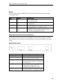
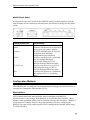
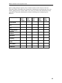
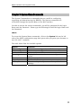
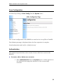
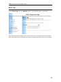
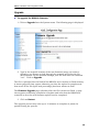
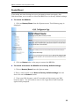
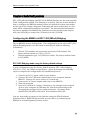
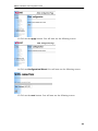
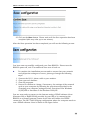
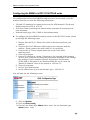
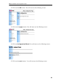
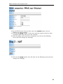
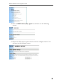
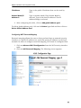
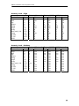
Gnet BB005x ADSL modem/router
*Configuration and Installation Guide*
BB005x Installation and Configuration Guide
TABLE OF CONTENTS
Chapter 1: Introduction ......................................................................................3
General .............................................................................................................3
Features Overview ............................................................................................3
About this manual..............................................................................................3
Chapter 2: General Connectivity .......................................................................5
Package Contents .............................................................................................5
Physical Configuration.......................................................................................5
Front Panel Indicators....................................................................................5
Back Panel Connector Ports and Switches ...................................................6
Configuration Methods ......................................................................................7
Web Interface ................................................................................................7
Command Line Interface (CLI).......................................................................8
Changing the settings of your computer............................................................9
Systems running Windows 95/98/Me.............................................................9
Systems running Windows 2000/XP............................................................10
Connection Parameters...................................................................................11
Chapter 3: System Menu Commands..............................................................13
Save Configuration..........................................................................................14
Authentication..................................................................................................14
Error Log .........................................................................................................17
Remote Access ...............................................................................................18
Upgrade ..........................................................................................................19
Restart/Reset ..................................................................................................20
Chapter 4: Basic Configurations .....................................................................21
Configuring the BB005x in RFC 1483 (MPoA) Bridging ..................................21
RFC 1483 Bridging mode using the factory default settings ........................21
RFC 1483 Bridged mode using non-default settings ...................................22
Configuring the BB005x in RFC 2516 PPPoE mode .......................................28
Other Configurations .......................................................................................37
Chapter 5: Advanced Features ........................................................................39
ADSL mode .....................................................................................................39
DHCP Server/Relay Agent ..............................................................................39
DNS Client ......................................................................................................40
DNS Relay ......................................................................................................40
IP Routes ........................................................................................................41
LAN Connections: ...........................................................................................42
Security ...........................................................................................................42
Security Interfaces .......................................................................................43
Adding a Security Interface..........................................................................43
Configuring NAT ..........................................................................................44
Firewall ........................................................................................................48
Universal Plug and Play (UPnP)......................................................................54
UPnP in BB005x ..........................................................................................54
2
BB005x Installation and Configuration Guide
Chapter 1: Introduction
General
Welcome to the Gnet BB005x series of high performance external Ethernet
ADSL Modem/Routers. The BB005x series includes two models: the BB0050
single port model and the BB0055 four port model. Both use GlobesapanVirata
chip-set technology and have a common set of features. Both models are ideal
for home or office installation, delivering high-speed connectivity,
comprehensive ADSL standards support and powerful network security
features.
Features Overview
The BB005x modem/routers are able to operate at speeds of up to 8Mbps
downstream and 1 Mbps upstream while supporting the T1.413, G992.1
(G.dmt) and G992.2 (G.lite) standards. Their advanced functionality includes:
•
•
•
•
•
•
Support for all major ATM based ADSL network protocols including RFC
1483 (MPoA) Bridging, RFC 1483 (MPoA) Routing, RFC 1577 (IPoA)
Routing, RFC 2516 (PPPoE) Routing and RFC 2364 (PPPoA) Routing
Software support for DHCP server/relay/client, NAT and PPPoE internal
client
Firewall capability with support for flexible security policies and intrusion
detection
Built in Application Layer Gateways (ALGs) and firewall triggers that
enable popular applications such as NetMeeting, FTP, VPN, etc. to
operate across NAT based network configurations
Easy configuration and administration through the Web interface or the
CLI interface using telnet or serial port access
Support for UPnP (Universal Plug and Play) standards when connected to
hosts running UPnP enabled operating systems
About this manual
Because of the commonality in features between BB0050 and BB0055, the
features and configuration procedures described in this manual apply to both
models. As such, except when explicitly stated otherwise, this document
describes the two units as one model: the BB005x.
3
BB005x Installation and Configuration Guide
Chapter 2, General Connectivity, provides information about the physical
characteristics of the BB005x, the necessary steps required to set up its
environment and details on how to access the configuration capabilities of the
unit.
Chapter 3, System Menu Commands, details the use of utility commands that
are useful in configuring, administering and maintaining the BB005x.
Chapter 4, Basic Configurations, includes step-by-step instructions on how to
configure the BB005x in some of the most popular ADSL configuration modes
including RFC 1483 (MPoA) Bridging and RFC 2516 (PPPoE)Routing.
Chapter 5, Advanced Features, describes some of the more complex features of
the BB005x. It includes information about Network Address Translation (NAT),
Security Interfaces, Firewall Configuration, UPnP compatibility, etc. For even
more detailed technical information please refer to the CLI Reference Manual on
the CD-ROM.
4
BB005x Installation and Configuration Guide
Chapter 2: General Connectivity
Package Contents
Before attempting to install and configure the BB005x Modem/Router please
verify that the package contains:
One BB005x Modem/Router
One 9VDC Power Supply Adapter
One RJ-11 Telephone Cable
One 10BaseT Ethernet straight through cable
One RS-232 Console Cable
Web Browser Configuration Instructions
Physical Configuration
Before installation, please examine the front and rear panels of the BB005x and
correctly identify the existing connectors, switches and indicators
Front Panel Indicators
BB0050
The table below lists the BB0050 Front Panel LED Indicators and describes
their significance.
LED
Pwr
ADSL
PC
RX/TX
Status
On
Off
On
Off
On
Off
Blinking
Off
Significance
Unit is powered on
Unit is powered off
ASDL link established and active
No ADSL link
PC link established and active
No PC link established or active
Transmitting or receiving data
No transmission or reception of data
5
BB005x Installation and Configuration Guide
BB0055
The table below lists the BB0055 Front Panel LED Indicators and describes
their significance.
LED
Power
Status
On
Off
DSL Link
On
Off
DSL/ACT
Blinking
Off
L1,L2, L3,L4 Red
Green
Off
Significance
Unit is powered on
Unit is powered off
ASDL link established and active
No ADSL link
Transmitting or receiving data
No transmission or reception of data
10MBPS PC link established and active
100MBPS PC link established and active
No PC link established or active
Back Panel Connector Ports and Switches
A diagram for the back panel of the BB0050 router/modem together with the
functionality of the connectors and switches are shown in the figure and table
below.
BB0050 Back Panel
Connector/Switch
ON/OFF
Power
Console
10/100 Base-T
ADSL
Functionality
Switches the unit on and off
Connects the device to an electrical
outlet using the power adapter
RS-232C interface that is used for
Command Line Interface configuration
(not required)
Connects the device to your PC’s
Ethernet port using an RJ-45
straight-through Ethernet cable
Connects the device to a telephone
jack using an RJ-11 telephone cable
6
BB005x Installation and Configuration Guide
BB0055 Back Panel
A diagram for the back panel of the BB0050 router/modem together with the
functionality of the connectors and switches are shown in the figure and table
below.
Switch/Connector
ON/OFF
Power
Console
Uplink
L1,L2,L3,L4
DSL
Functionality
Switches the unit on and off
Connects the device to an electrical
outlet using the power adapter
RS-232C interface that is used for
Command Line Interface
configuration (not required)
Connects the device to a standard
port on another Ethernet
hub/switch using an RJ-45
straight-through Ethernet cable
Connects the device to your PC’s
Ethernet port using an RJ-45
straight-through Ethernet cable
Connects the device to a telephone
jack using an RJ-11 telephone
cable
Configuration Methods
The BB005x can be configured and administered through the Web interface or
through the Command Line Interface (CLI).
Web Interface
The recommended and most efficient way to configure the BB005x
modem/router is by using a Web Browser to access the Web interface. Most
features and operation modes can be enabled through this interface. Chapter 3
of the manual contains step-by-step instructions on how to configure the
BB005x for some of the most popular ADSL configurations modes while using
the Web interface
7
BB005x Installation and Configuration Guide
Command Line Interface (CLI)
The BB005x can also be configured through the Command Line Interface (CLI),
accessible via Telnet or locally through the RS-232C serial port. This method is
only recommended when more complex features and settings are required. The
following paragraphs briefly describe how to initiate access to the CLI interface
of the BB005x. For detailed information regarding the available CLI commands
and their syntax, please contact your Internet Service Provider or please refer to
the CLI Reference Manual on the CD-ROM. .
IMPORTANT NOTE: Please use the CLI only when the intended operation
cannot be performed via the BB005x Web interface.
CLI access via Telnet
You can access the CLI interface via Telnet from a computer connected to the
local LAN by going through the following procedure:
You must set up the TCP/IP properties for your LAN card to be on the same
subnet as the BB005x (192.168.7.2 and 255.255.255.0).
Turn on the modem. From the MS-DOS prompt, telnet into the Ethernet port of
the BB005x by typing the word telnet followed by the IP address of the Ethernet
interface. Example: “telnet 198.168.7.1”
You will be prompted for the Login Name and the Password. Please type the
following for both the Login Name and the Password:
admin
The “Login Successful” message will appear followed by the BB005x prompt:
-->
You can begin to enter the CLI commands.
CLI Access via serial console port
You can also access the CLI interface from a computer or a terminal connected
to the serial console port of the BB005x through an RS-232C serial cable.
Turn on the modem. Open HyperTerminal (available with Windows systems) or
an equivalent terminal emulation application program. Select the appropriate
COM port and ensure that the COM port settings are: 9600 bps, 8 data bits, 1
stop bit, No Parity, No Flow Control
8
BB005x Installation and Configuration Guide
Turn on the modem. In the HyperTerminal window, press the Enter key a
couple of times until you are prompted to enter the Login Name and the
Password. Please type the following for both the Login Name and the Password:
admin
The “Login Successful” message will appear followed by the BB005x prompt:
-->
You can begin to enter the CLI commands.
Changing the settings of your computer.
In order to configure the BB005x or to access the Internet through the modem
after the configuration is complete, the network card in the user’s computer
must be configured with the appropriate settings. Those settings are mainly
related to whether the IP address of the network card will be set to a
predetermined value or if it is going to be obtained automatically every time the
computer connects to the network. The steps that need to be taken also depend
upon the operating system running on the computer.
Systems running Windows 95/98/Me
Procedure A - Assigning a predetermined IP address value (to be referred below
as “known IP address”) to the network card in your computer.
1. In the Windows task bar, click on the Start button, highlight Settings
and click on Control Panel.
2. Double click the Network icon
3. Click on the network component TCP/IP for your Network Interface Card
(for example: Realtek RTL8139 PCI Fast Ethernet NIC) and then click on
the Properties button. If you have multiple TCP/IP listings, please make
sure that you select the listing associated with your NIC.
4. In the TCP/IP Properties dialog box, click on the IP Address tab and then
click on the option “Specify an IP Address” (make sure that the black
dot is beside this option).
5. Set the IP Address to the value indicated by “known IP address” and set
the Subnet Mask to 255.255.255.0
6. Click on the Gateway tab and then remove any installed Gateway.
7. Click on the DNS Configuration tab and then click on the option
“Disable DNS” (make sure that the black dot is beside this option). Do
not change any other settings.
8. Click on the OK button twice to confirm and save your changes.
9. Click on the Yes button to restart your computer.
9
BB005x Installation and Configuration Guide
Procedure B – Setting the Network Card in your computer to automatically
obtain an IP address.
1. In the Windows task bar, click on the Start button, highlight Settings
and click on Control Panel.
2. Double click the Network icon
3. Click on the network component TCP/IP for your Network Interface Card
(for example: Realtek RTL8139 PCI Fast Ethernet NIC) and then Click on
the Properties button. If you have multiple TCP/IP listings, please make
sure that you select the listing associated with your NIC.
4. In the TCP/IP Properties dialog box, click on the IP Address tab and then
click on the option “Obtain an IP Address automatically”.
5. Click on the Gateway tab and then remove any installed Gateway.
6. Click on the DNS Configuration tab and then click on the option
“Disable DNS” (make sure that the black dot is beside this option). Do
not change any other settings.
7. Click on the OK button twice to confirm and save your changes.
8. Click on the Yes button to restart the computer.
Systems running Windows 2000/XP
Procedure C - Assigning a predetermined IP address value (to be referred below
as “known IP address”) to the network card in your computer.
1. In the Windows task bar click on the Start button, highlight Settings and
click on Control Panel.
2. Double click the Network and Dial Up Connections icon
3. In the Network and Dial Up Connections window, right click once on the
Local Area Connections icon and then click on Properties.
4. In the Local Area Connections Properties dialog box, click on Internet
Protocol (TCP/IP) and then click on Properties.
5. In the Internet Protocol (TCP/IP) Properties dialog box, click on the
option “Specify an IP Address” (make sure that the black dot is beside
this option).
6. Set the IP Address to the value indicated by “known IP address” and set
the Subnet Mask to 255.255.255.0
7. Click on the option “Obtain DNS server address automatically” (make
sure that the black dot is beside this option). Do not change any other
settings.
8. Click on the OK button twice to confirm and save your changes and then
close the Control Panel.
10
BB005x Installation and Configuration Guide
Procedure D - Setting the Network Card in your computer to automatically
obtain an IP address.
1. In the Windows task bar, click on the Start button, highlight Settings
and click on Control Panel.
2. Double click the Network and Dial Up Connections icon
3. In the Network and Dial Up Connections window, right click once on the
Local Area Connections icon and then click on Properties.
4. In the Local Area Connections Properties dialog box, click on Internet
Protocol (TCP/IP) and then click on Properties.
5. In the Internet Protocol (TCP/IP) Properties dialog box, click on the
option “Obtain an IP address automatically” (make sure that the black
dot is beside this option).
6. Click on the option “Obtain DNS server address automatically” (make
sure that the black dot is beside this option). Do not change any other
settings.
7. Click on the OK button twice to confirm and save your changes and
then, close the Control Panel.
Connection Parameters
The BB005x, like all ADSL access devices, is only one component of the
complex network infrastructure that makes its operation possible. Its
configuration depends on many parameters that are external to the BB005x. In
order to properly configure the BB005x, it is necessary to obtain all of the
required connection parameters and configuration data from the Internet
Service Provider and/or the Network Administrator. The following list contains
various types of information that might be required in configuring the BB005x
-
VPI and VCI values
User Name
Password
Default WAN Gateway
DNS Relay (Enable/Disable)
DNS Server (Primary)
DNS Server (Secondary)
LAN IP address
LAN Subnet Mask
Remote Gateway
NAT enabled or disabled
The PPP Authorization type
The Framing Mode
WAN IP
WAN Subnet Mask
11
BB005x Installation and Configuration Guide
Most configurations require only a limited subset of the items on the list.
The table below illustrates the parameters information requirements for a few
ADSL configurations. Please make sure that you obtain the information from
your ISP or Network Administrator before installing and configuring the
BB005x.
RFC
1483
Bridged
RFC
1483
Routed
RFC
1577
IPoA
RFC
2364
PPPoA
RFC
2516
PPPoE
Description
VPI
VCI
Encapsulation
method
Static WAN IP
address
Netmask
Gateway
Authentication
mode
User Name
Password
12
BB005x Installation and Configuration Guide
Chapter 3: System Menu Commands
The System Commands are commands that are useful in configuring,
upgrading and administering the BB005x. The System commands are
accessible through the System Menu of the Web interface.
In order to access the various commands, you will be prompted for the Login
Name and the Password. Please type the following for both the Login Name and
the Password:
admin
To access the System Menu commands, click on the System link on the left
side of the ADSL configuration page that opens after you point your browser to
the 192.168.7.1 address.
The table below lists the available options.
Option
Save config
Clear config
Authentication
Error log
Remote access
Upgrade
Restart/Reset
Function
Saves current configuration to flash memory
Clears current configuration
Creates, edits and deletes user accounts
Displays information about recent configuration
errors
Allows remote administration
Updates the firmware
Restarts and optionally restores factory default
settings
13
BB005x Installation and Configuration Guide
Save Configuration
Activated by clicking on Save Config from the System menu
The current configuration of the BB005x is saved in the im.conf file to FlashFS .
The following message is displayed when the Save operation is complete.
Saved information model to file //flashfs/im.conf
Authentication
This option helps administer the accounts of users who have access to the
BB005x.
► To create, edit or delete user accounts:
1. Select Authentication from the System menu. A table appears on
the Authentication page that shows all of the current login
accounts
14
BB005x Installation and Configuration Guide
For each user, the table on the screen lists their name, whether they are
authorized to log in and also offers a space for entering comments.
► To create a new account:
1. Click on Create a New User.
2. Type in the new user’s name, password and comment (optional) in the
text boxes provided.
3. At May login? select either true or false.
Selecting true enables the user to access the Web interface.
Selecting false will prevent the user from accessing the Web interface.
4. Click on Create.
The Authentication page displays again, but the user information you have
just typed in is now displayed inside the table. You will also notice that the
Authentication page table contains an Edit user hyperlink for each user
account entry.
15
BB005x Installation and Configuration Guide
► To edit any account information:
1. Click on one of the corresponding Edit user links.
2. Edit the information in the text boxes and then click on Apply.
► To delete an account:
1. Click on Delete user to delete a user account.
After editing or deleting a user account, the Authentication page displays the
user information including the changes that were just made.
16
BB005x Installation and Configuration Guide
Error Log
Select Error Log from the System menu. The following page is displayed:
The table shows all configuration errors, the time (in seconds since the system
was restarted) of the error and the process during which the error has occurred.
17
BB005x Installation and Configuration Guide
Remote Access
Remote access allows temporary remote access to the system using Network
Address Translation (NAT).
Click on Remote Access from the System menu. NAT must be configured first
before enabling remote access so, if it is not configured already, click on the
NAT hyperlink on the page below or click on Advanced
Configuration/Security from the left-hand window.
After completing the NAT configuration, click on Remote Access and type in
the amount of time desired for remote access
The Remote Access page will appear and display the number of seconds
remaining for remote access. Click on Disable to stop remote access before the
time has elapsed.
18
BB005x Installation and Configuration Guide
Upgrade
► To upgrade the BB005x firmware:
1. Click on Upgrade from the System menu. The following page is displayed:
2. Type in the network location of the new firmware image you want to
upload or use Browse to look through the network and select the file.
New firmware can be obtained through your ISP and uses the extension
“.tar”. Click on Upgrade.
The file is uploaded into the RAM of the BB005x and is written to flash memory.
A status page will then appear informing you that the upload is complete and
how much of the file (bytes and percentage) has been written to flash.
The Firmware Upgrade page refreshes after the file is written to flash. A page
then appears confirming completion of update and asks that the BB005x be
restarted so that the new firmware upload can be completed.
3. Click on Restart.
The upgrade process may take up to 10 minutes to complete so please be
patient during the process.
19
BB005x Installation and Configuration Guide
Restart/Reset
If you make an error during set-up or just want to start over again, this
function allows you to restart or reset the BB005x to its factory default settings.
► To restart the BB005x:
1. Click on Restart/Reset from the System menu. The following page is
displayed:
2. Click on Restart title in the page to restart the BB005x.
► To restart and restore the BB005x to is factory default settings:
1. Click on Restart/Reset from the System menu.
2. Place a check mark in the Reset to factory default settings box and
then click on the Restart button.
3. Close your Web browser, wait 45 seconds and then open your Web
browser again. You will need to enter in the Login Name and Password
again when prompted.
20
BB005x Installation and Configuration Guide
Chapter 4: Basic Configurations
RFC 1483 (MPoA) Bridging and RFC 2516 (PPPoE) Routing are the most popular
ADSL configuration modes. The following is a step-by-step set of instructions of
how to configure the BB005x modem/router for operation in these two modes.
At the end of the chapter, diagrams illustrating the basic architecture of a few
other ADSL configuration modes are provided. For more detailed information
on how to configure the BB005x for operation on those modes please inquire
with your ISP and/or consult the CLI manual on the CD-ROM.
Configuring the BB005x in RFC 1483 (MPoA) Bridging
This is BB005x factory default mode. For configuration of the unit in RFC 1483
(MPoA) Bridging mode, your ISP needs to provide you with the following
information:
•
•
VPI and VCI numbers for connection across the ATM network. The
factory default values are VPI=0, VCI=35
ATM encapsulation type: LLC/SNAP or VcMux. The factory default value
is LLC/SNAP.
RFC 1483 Bridging mode using the factory default settings
If your configuration uses the factory default settings: RFC 1483 Bridging,
VPI/VCI = 0/35, LLC/SNAP encapsulation - please go through the following
steps to complete the configuration and installation process.
1. Connect the RJ-11 phone cable to your modem.
2. Connect the RJ-45 Ethernet cable between your computer and the
BB005x. Remove the serial cable if it is connected.
3. Connect the AC Power adapter and turn on the BB005x.
4. Close all programs.
5. Proceed to confirm or change, if necessary, the settings of the network
card on your computer by following the procedures described in the
Changing the settings of your computer section: Procedure B for
Windows 95/98/ME or Procedure D for Windows 2000/XP.
You are now ready to connect to the Internet using the PPPoE software
(Enternet 300 or RASP PPPoE) provided by your ISP or by connecting the
BB005x to a firewall/gateway/router device.
21
BB005x Installation and Configuration Guide
RFC 1483 Bridged mode using non-default settings
If your configuration does not use the factory default settings, please go
through the following steps in order to configure the Gnet BB005x
modem/router.
1. Ensure that the RJ-11 Phone Line cable is disconnected from your
modem.
2. Connect the RJ-45 Ethernet cable between your computer and the
modem. Please remove the serial cable if it is connected.
3. Connect the AC Power adapter and turn on the Gnet ADSL
modem/router.
4. Close all programs.
5. Proceed to confirm or change, if necessary, the settings of the network
card on your computer by using the procedures described in the
Changing your computer settings section: Procedure A for Windows
95/98/ME or Procedure C for Windows 2000/XP. In all cases the
“known IP address” value to be entered is 192.168.7.2
6. Close all programs.
7. Launch your web browser.
8. In the address bar of your web browser type: 192.168.7.1
You will now see the following screen:
9. Click on System.
10. Click on Clear config.
11. For the User Name type admin (lower case). For the Password type
admin (lower case)
12. Click on the OK button. You will now see the following screen:
22
BB005x Installation and Configuration Guide
13. Click on the Apply button. You will now see the following screen:
14. Click on Configuration Wizard. You will now see the following screen:
15. Click on the next button. You will now see the following screen:
23
BB005x Installation and Configuration Guide
16. Click on the Apply button. You will now see the following screen:
17. In the Description field you must enter a name (Example: RFC 1483
Bridging)
18. In the VPI and VCI fields, enter the values provided to you by your ISP.
19. In the Encapsulation method field, enter either LLC/SNAP or VcMux
(null) based on the information provided to you by your ISP.
20. Click on the Apply button. You will now see the following screen (Do not
make any changes):
24
BB005x Installation and Configuration Guide
21. Click on the Apply button. You will now see the following screen:
22. Click on Save config. You will see the following screen:
25
BB005x Installation and Configuration Guide
23. Click on the Save button. Please wait until the Save operation has been
completed (this may take up to one minute).
After the Save operation has been completed you will see the following screen:
You have now successfully configured your Gnet BB005x. Please turn the
BB005x power off, wait 5 seconds and then turn it back on.
►
To complete the installation process and to ensure that your network
card properties settings are correct, please go through the following
steps.
1.
2.
3.
4.
Connect the RJ-11 phone cable to your modem.
Close your web browser.
Close all programs.
Proceed to confirm or change, if necessary, the settings of the network
card on your computer by following the procedures described in the
Changing your computer settings section: Procedure B for Windows
95/98/ME or Procedure D for Windows 2000/XP.
You are now ready to connect to the Internet using a PPPoE software client
(Enternet 300 or RASP PPPoE) provided by your ISP or by connecting the
BB005x to a firewall/gateway/router device that will initiate the PPPoE
connection. The RFC 1483 bridging configuration where the computer needs to
run a PPPoE software client is shown in the figure below.
26
BB005x Installation and Configuration Guide
PC1 IP Address:
Obtained by
PPPoE software
WAN IP Address:
WAN Gateway
IP Address:
203.18.6.1(example)
Gnet BB005x
LAN IP Address:
LAN
WAN
The RFC 1483 (MPoA) Bridging configuration can also be used without PPPoE
software when the computer(s) are bridged through the BB005x to the ISP’s
LAN. This type of configuration, called transparent bridging, is shown in the
figure below where 2 computers are connected on the Ethernet Interface of
BB0055. The 2 computers have public IP addresses on the same subnet with
the WAN Gateway. Those addresses are entered either manually or are assigned
by a DHCP server at the ISP site. Because the BB0055 acts as a transparent
bridge, there is no IP address on the WAN or LAN side of the modem/router.
PC1 IP Address:
203.18.6.2
WAN IP Address:
WAN Gateway
IP Address:
203.18.6.1
Gnet BB0055
PC2 IP Address:
203.18.6.3
LAN IP Address:
LAN
WAN
27
BB005x Installation and Configuration Guide
Configuring the BB005x in RFC 2516 PPPoE mode
For configuration of the Gnet BB005x modem/router in this mode, your ISP
needs to provide you with the following information:
•
•
•
VPI and VCI numbers for connection across the ATM network. The factory
default values are VPI=0, VCI=35
Your User Name (including the domain name extension if necessary) and
your Password
Authentication type: PAP, CHAP or No Authentication
► To configure the Gnet BB005x modem/router in the RFC 2516 mode, please
go through the following steps:
1. Ensure that the RJ-11 Phone Line cable is disconnected from your
modem.
2. Connect the RJ-45 Ethernet cable between the computer and the
modem. Please remove the serial cable if it is connected.
3. Connect the AC Power adapter and turn on the Gnet ADSL
modem/router.
4. Close all programs.
5. Proceed to confirm or change, if necessary, the settings of the network
card on your computer by using the procedures described in the Change
the settings of your computer section: Procedure A for Windows
95/98/ME or Procedure C for Windows 2000/XP. In all cases the
“known IP address” value to be entered is 192.168.7.2
6. Close all programs.
7. Launch your web browser.
8. In the address bar of your web browser type: 192.168.7.1
You will now see the following screen:
9. Click on System.
10. Click on Clear config.
11. For the User Name type admin (lower case). For the Password type
admin (lower case).
28
BB005x Installation and Configuration Guide
12. Click on the OK button. You will now see the following screen:
13. Click on the Apply button. You will now see the following screen:
14. Click on Configuration Wizard. You will now see the following screen:
15. Click on the next button. You will now see the following screen:
29
BB005x Installation and Configuration Guide
16. Select the RFC 2516 (PPPoE) routed mode and click on the Apply button.
You will now see the following screen:
17. In the Description field, please enter a name (Example: RFC 2516
Routing)
18. In the VPI and VCI fields, enter the values provided by your ISP.
19. Select the authentication mode (PAP, CHAP or No Authentication) based
on the information provided by your ISP.
20. In User name field, enter your user name (example : jsmith) or the user
name plus the domain information (example: [email protected]) provided by
your ISP. This information is case sensitive.
21. In the Password field, enter the Password provided to you by your ISP.
This information is case sensitive.
22. Place a check mark beside the Advanced Configuration option.
23. Click on the Apply button.
You will see the following screen:
30
BB005x Installation and Configuration Guide
24. In the PPPoE Auto Connect field, select the enabled option. Do not
change any other settings.
25. Click on the Apply button. Please wait until the Apply action has been
completed (this may take up to one minute).
26. After the Apply action has been completed, you will see the following
screen (Do not change any settings):
27. Click on the Apply button. You will now see the following screen (Do not
change any settings):
31
BB005x Installation and Configuration Guide
28. Click on the Apply button. You will now see the following screen:
29. Click on Advanced Configuration. You will now see the following screen:
32
BB005x Installation and Configuration Guide
30. Click on DHCP server/relay agent. You will now see the following
screen:
31. Select the DHCP server option and click on the Configure button. You
will now see the following screen:
33
BB005x Installation and Configuration Guide
32. In the Starting IP Address field, enter 192.168.7.150 (if it is already
entered, you do not need to enter the address again).
33. In the Ending IP Address field , enter 192.168.7.200 (if it is already
entered, you do not need to enter the number again).
34. In the Default Lease Time field, enter 43200 (if it is already entered, you
do not need to enter the number again).
35. In the Maximum Lease Time field, enter 86400 (if it is already entered,
you do not need to enter the number again).
36. Place a check mark beside Use the Router as the DNS Server (if it is
already checked, DO NOT remove the check mark).
37. Place a check mark beside Use the Router as the Default Gateway (if it is
already checked, DO NOT remove the check mark).
38. Click on the Apply button. You will now see the following screen
39. Click on System. You will now see the following screen:
34
BB005x Installation and Configuration Guide
40. Click on Save config. You will now see the following screen:
41. Click on the Save button. Please wait until the Save operation has been
completed (this may take up to one minute).
After the Save operation has been completed you will see the following screen:
35
BB005x Installation and Configuration Guide
You have now successfully configured your Gnet BB005x modem/router.
Please turn off the BB005x power, wait 5 seconds and then turn it back on.
► To complete the installation process and to ensure that your network
card properties settings are correct, please go through the following
steps:
1. Connect the RJ-11 phone cable to your modem.
2. Close your web browser.
3. Proceed to confirm or change, if necessary, the settings of the network
card on your computer using the procedures described the Change the
settings of your computer: Procedure B for Windows 95/98/ME or
Procedure D for Windows 2000/XP
If you have configured your Gnet BB005x for RFC 2516 Routed (PPPoE) mode,
please continue with the following steps:
Windows 95/98/ME:
1. Close all programs.
2. Click on the Start button.
3. Click on Run and in the Open field enter: winipcfg
4. Under Ethernet Adapter Information, use the drop down menu to select your
network card (Example: Realtek 8139-series PCI NIC).
5. Click on the Release button and wait for about 5 seconds.
6. Click on the Renew button.
7. Close the Winipcfg program.
You have completed the configuration and installation process for the RFC 2516
Routed (PPPoE) mode and you can start accessing the Internet by launching
your browser.
Windows 2000/XP:
1. Close all programs.
2. Click on the Start button.
3. Click on Run and in the Open field enter: cmd
4. From the prompt, type in ipconfig/release and then press the Enter/Return
key.
5. From the prompt, type in ipconfig/renew and then press the Enter/Return
key.
6. From the prompt, type in exit and then press the Enter/Return key.
You have completed the configuration and installation process for the RFC 2516
Routed (PPPoE) mode and you can start accessing the Internet by launching
your browser.
The figure below shows a typical RFC 2516 routing configuration with 2
computers on the Ethernet interface of the BB0055 forming a Local Area
Network with private IP addresses assigned by the DHCP server inside the
36
BB005x Installation and Configuration Guide
BB0055. The BB0055 PPPoE built-in client will obtain the IP address on the
WAN side during the PPP session with the server at the ISP site. The NAT
(Network Address Translation) feature maps requests from one or more
computers on the private network behind the BB0055 onto the single public
WAN side IP address.
PC1 IP Address:
192.168.7.2
WAN IP Address: To be
obtained by BB0055
PPPoE client
WAN Gateway
IP Address:
203.18.6.1
Gnet BB0055
PC2 IP Address:
192.168.7.3
LAN IP Address:
192.168.7.1
LAN
WAN
Other Configurations
As mentioned at the beginning of Chapter 3, there are several other
configuration modes for ADSL modem/routers beside RFC 1483 (MPoA)
Bridging and RFC 2516 (PPPoE) Routing. The diagrams below illustrate the
basic architectures of such configurations.
RFC 1483 Routing with NAT enabled
PC1 IP Address:
192.168.7.2
WAN IP Address:
203.18.6.15
WAN Gateway
IP Address:
203.18.6.1
Gnet BB0055
PC2 IP Address:
192.168.7.3
LAN IP Address:
192.168.7.1
LAN
WAN
37
BB005x Installation and Configuration Guide
In the configuration above, the 2 computers behind BB0055 have private IP
addresses assigned by the DHCP server inside BBB0055. The WAN IP address
is a public address entered manually or automatically assigned by the DHCP
server at the ISP site. The NAT feature inside BB0055 translates request
between the private IP addresses of the computers and the public IP address of
the BB0055 Wan interface.
RFC 1483 routed with NAT disabled
PC1 IP Address:
202.24.8.2
WAN IP Address:
203.16.6.15
WAN Gateway
IP Address:
203.18.6.1
Gnet BB0055
PC2 IP Address:
202.24.8.3
LAN IP Address:
202.24.8.1
LAN
WAN
In the configuration above, the 2 computers behind BB0055 have public
address on the same segment defined on the LAN side of the BB0055. Those
addresses could be manually entered or could be automatically assigned by the
DHCP server inside the BB0055 or by the DHCP server at the ISP side using the
DHCP relay function in BB0055. The public WAN IP address could be manually
entered or assigned by the DHCP server at the ISP site at the request of the
DHCP client in the BB0055.
38
BB005x Installation and Configuration Guide
Chapter 5: Advanced Features
ADSL mode
The BB005x allows users to configure the modem for the appropriate ADSL
standard used in their network: Multimode, T.413 ANSI, G.992.2 dmt or
G.992.2 Lite.
► To configure the ADSL mode:
1. Click on Advanced Configuration
2. Click on ADSL mode from the Advanced Configuration menu
3. Select from one of four ADSL modes on this page: multi, ansi, glite and
gdmt. If no special setting is required, select the mode provided by your
ISP.
DHCP Server/Relay Agent
The BB005x can be configured to act as a DHCP client, server or agent.
As a DHCP client the BB005x obtains its IP address from the DHCP server that
is normally located at the ISP site.
As a DHCP server, the BB005x, assigns IP addresses to computer hosts located
behind the modem router in a NAT arrangement
As a DHCP relay, the BB005x passes through messages to and from the
computer hosts behind the router that are obtaining IP addresses from the
DHCP server at the ISP location
► To configure the DHCP server:
1. Click on Advanced Configuration
2. Click on DHCP Server/Relay Agent from the Advanced Configuration
menu
3. The DHCP Server page appears. The values displayed are the default
settings for the DHCP server.
4. Click on Configure to change the DHCP server configuration. Parameters
that can be reconfigured on this page:
-
DHCP address range
Global default and maximum lease times
Primary and secondary DNS server addresses
39
BB005x Installation and Configuration Guide
-
Gateway address
5. Click on Apply to confirm the new configuration.
If any other parameter changes need to be made to the DHCP server, click on
Advanced Options at the bottom of the DHCP Configuration page.
DNS Client
This option allows the creation of a domain search list. The DNS client in
BB005x uses this list when a user asks for the IP address list for an incomplete
domain name.
► To configure the DNS client:
Click on DNS client from the Advanced Configuration menu
► To add a server reference to the DNS client:
1. Type the IP address of the server into the DNS Servers text box.
2. Click on Add. The IP address appears in the DNS servers table. Up to
three server IP addresses can be added. To delete an IP address entry
from the list, click on its Delete button.
► To configure DNS search:
1. Type search string in Domain search order text box
2. Click on Add
The search string appears in the Domain search order table. Up to six search
strings can be added. To remove a string from the list, click on the Delete
button.
DNS Relay
This option allows enabling, disabling and configuring of the DNS relay.
► To configure the DNS relay:
Click on DNS relay
► To enable and configure the DNS relay:
1. Click on Enabled
2. Click on Configure
40
BB005x Installation and Configuration Guide
The page that opens page allows you to add the IP address of a DNS server to
the DNS relay’s list of server IP addresses.
3. Type the IP address in the DNS server IP address text box
4. Click on Apply
A page appears with the following message:
The DNS relay is enabled. Relaying to:
192.168.100.10
IP Routes
This option allows you to create static IP routes to destination addresses via an
IP interface name or a Gateway address
Click on IP routes from the Configuration menu
The page that opens displays:
-
Destination IP address
Gateway address
Netmask address
► To edit the destination, gateway and netmask address of a route:
Click the relevant textbox, update the information and click on Apply
► To edit the cost and interface setting of the route:
Click on Advanced Options for the specific route and update the relevant
information. Click on OK.
► To create a new route:
1. Click on Create new IP V4 route
2. Complete the Create IP V4 Route form to configure the route.
3. Click OK.
The Edit Routes page appears and displays the details of the route you have
just configured.
41
BB005x Installation and Configuration Guide
LAN Connections:
The option allows you to configure the IP address and subnet of the default LAN
connection and create/delete LAN services.
► To configure a LAN Connection:
1. Click on Advanced Configuration
2. Click on LAN connections
The following parameters can be configured:
Name
Name of the LAN port used by the service
Description
Description of the service
Creator
The methods used for creating the service: CLI,
Web Interface or Factory Default.
► To create a new LAN service:
1. Click on Create a new service command. Service options are displayed.
Select the service that you want to create.
2. Click on Configure to display the service configuration page. Enter the
relevant information to the service that you are creating.
3. Click on Apply.
The LAN connection page appears and displays the details of the service that
you have just created.
► To delete a LAN service:
1. Click on LAN service description link.
2. Check the details of the LAN service of the service you want to delete.
3. Click on Delete this connection.
Security
Security is an important consideration for any network, even for networks that
include only one host computer. Security measures normally involve protecting
the network against attacks or unwarranted access from the external network
and setting policies that control both the inbound and outbound flow of data
packets. Ensuring that all required applications are able to function properly in
the context of those policies is also an essential part of implementing an
effective network security environment.
The BB005x features a powerful set of advanced security features including a
configurable firewall, NAT, DMZ, Intrusion Detection, Triggers and Application
42
BB005x Installation and Configuration Guide
Layer Gateways (ALGs). These features ensure secure and effective access for
many popular Internet applications. The BB005x can also function as an IGD
(Internet Gateway Device) in accordance with the Universal Plug and Play
(UPnP) standards. This capability further enhances the flexibility of the unit to
support secure access for a large number of applications.
Security Interfaces
One important concept that relates to NAT and the security capabilities of
BB005x is the concept of security interface.
The configuration process requires that security is enabled and security
interfaces be added before NAT or firewall features can be configured. The
BB005x supports 3 types of security interfaces: external, DMZ (demilitarized
zone) and internal. Each interface can be adjusted to allow or block certain
protocols or types of access.
In order for NAT or firewall triggers to be configured, at least one of the
following pair of interfaces needs to be defined.
•
•
•
External – Internal
External – DMZ
DMZ - Internal
The DMZ is normally a network area that is protected from unauthorized access
coming from the external network so that certain computer hosts (for example,
a Web Server) can be placed on the DMZ where they can be accessed by
requests from the outside world and still be protected against many security
threats.
Any of the 3 pairs of interfaces above can be configured for NAT operation. The
figure below illustrates security interfaces of the BB005x. Please note that
BB005x has no distinct physical Ethernet port for the DMZ and the distinction
between computer hosts belonging to the internal network and those on the
DMZ in entirely implemented in firmware.
DMZ
BB005x
Adding a Security Interface
► To add a Security Interface:
Internal
Security
Interface
1. Click on Advanced Configuration and
screen will appear:
DMZ
External
theSecurity
n on Security.
Interface
The following
Security
Interface
Internal Network
43
BB005x Installation and Configuration Guide
2. Make sure that security is enabled. If not, please check the button beside
Enabled.
3. Click on Add Interface from the Security Interfaces section to display
the Add Interface page.
4. Click on the Name drop down list and select the LAN service that you
want to base the security interface on.
5. Click on the Interface Type drop down list to specify the type of
interface added: external, internal or DMZ.
6. Click on Apply. The Security page appears. This page has a table that
includes information about each security interface that you created.
► To delete the security interface:
1. Click on Delete Interface to display Security: Delete Interface page.
2. Check details and click on Delete.
Configuring NAT
NAT (Network Address Translation) is essentially a mechanism that will
multiplex a multitude of private IP addresses onto a single public IP address.
This allows a number of computer hosts to share a public IP address on the
Internet.
44
BB005x Installation and Configuration Guide
The type of NAT supported by BB005x is often called NAPT (Network Address
Port Translation) because it maps public addresses to address/port
combinations on the private network. NAT also brings inherent firewall
capabilities to the router since it will not allow any inbound packets that were
not the result of initial requests from hosts on the private network. When
certain types of access or protocols need to be allowed to pass through a NAT
interface, certain techniques and features such as port triggers, ALGs or UPnP
are often used to allow this access. In the BB005x, NAT is always associated
with a pair of security interfaces.
► Configuring NAT:
Enable security and add the two different security interfaces between which you
wish to enable NAT (see previous section)
When you have created more than one security interface, the NAT column
informs you that you can enable NAT between the two interfaces. For example,
if you create an external interface and internal interface, the table will look as
follows:
The NAT column informs you that you can enable NAT to the internal
interfaces.
To enable NAT between the external interface and the internal interface, click
on Enable NAT to enable NAT to the internal interfaces. The Security page is
refreshed and NAT is enabled.
► To disable NAT:
Click on Disable NAT to internal interfaces.
45
BB005x Installation and Configuration Guide
Enabling NAT between interfaces allows configuration of global addresses or
configuration of reserved mapping.
Configuring NAT Global Addresses
Configuring a global address pool enables the user to define a pool of public
network addresses that NAT can use when translating requests originating from
private addresses behind NAT. To configure global addresses, NAT must be
configured first.
1. Click on NAT Advanced Configuration from the NAT security interface
table.
2. Click on Add Global Address Pool. The following screen will appear:
This page allows you to create a pool of public IP addresses that can be used by
NAT.
3. Fill in the required fields as follows:
Interface type
The internal interface that you want to map your
external IP addresses to. Select from a drop down
list.
Use subnet
configuration
Determines how IP addresses are specified.
Select either Use Subnet Mask or Use IP Address
Range (first and last IP address) from a drop down
list.
46
BB005x Installation and Configuration Guide
IP address
Type in the public IP address that can be used by
NAT.
Subnet Mask/IP
Address 2
Type in subnet mask if Use Subnet Mask is
selected. Type in the last IP address if Use IP
Address Range is selected.
4. After configuring the table, click on Add global address pool.
To delete global address pool, click on the Delete hyperlink and then click on
Delete Global Address Pool.
Configuring NAT Reserved Mapping
Reserved mapping allows the user to direct packets from an external security
interface or a public IP address to a particular private IP address on the local
network. In order to configure reserved mapping, NAT must be configured first.
1. Click on Advanced NAT Configuration from the NAT security interface
table.
2. Click on Add Reserved Mapping. The following screen appears:
47
BB005x Installation and Configuration Guide
3. Fill in the required fields as follows:
Global IP Address
If mapping from a public IP address, type the
address here. If mapping from a security interface,
type 0.0.0.0
Internal IP Address
The private IP address of the host on your
network.
Transport Type
Specify the transport protocol used by the data
packets coming from outside the local network
(e.g. TCP or UDP).
Port Number
Select the port number used by the transport
protocol.
4. After configuring the table, click on Add reserved mapping.
To delete a reserved mapping setup, click on Delete hyperlink and then click on
Delete Reserved Mapping.
Firewall
A firewall is a security system that acts as a protective boundary between a
network and the outside world. The BB005x firewall features provide effective
protection from unauthorized access and threats from the outside network
while allowing for flexible security policies that can control both the outbound
and inbound data traffic. Using the BB005x configuration procedures, security
policies can be adjusted in every detail in order to fit the specific requirements
of any network.
Setting Security Levels
For situations when detailed customization of the security policy is not
necessary, BB005x offers 3 pre-set levels of security: low, medium and high.
► To select one of the levels of security:
1. Click on Advanced Configuration and then on Security Level
2. Click on the desired level: high, medium, low
3. Click on Change Level
The following tables show the protocols allowed to cross the firewall for each
security level, in both directions for each type of security interface.
X – access blocked
Yes – access allowed
48
BB005x Installation and Configuration Guide
Security Level = High
External/Internal
In
Out
X
Yes
X
Yes
X
X
X
X
X
Yes
X
Yes
X
X
X
X
X
Yes
X
X
X
X
X
X
External/DMZ
In
Out
Yes Yes
X
Yes
X
Yes
X
X
Yes Yes
Yes Yes
X
X
X
X
X
Yes
X
X
X
X
X
X
DMZ/Internal
In
Out
Yes
Yes
X
Yes
X
Yes
X
X
Yes
Yes
Yes
Yes
X
X
X
X
X
Yes
X
X
X
X
X
X
Security Level = Medium
External/Internal
Protocol
Port
In
Out
http
80
X
Yes
dns
53
X
Yes
ftp
21
X
Yes
telnet
23
X
Yes
smtp
25
X
Yes
pop3
110
X
Yes
nntp
119
X
Yes
Real aud./vid. 7070
Yes
X
Icmp
N/A
X
Yes
H.323
1720
X
Yes
T.120
1503
X
Yes
SSH
22
X
Yes
External/DMZ
In
Out
Yes
Yes
Yes
Yes
Yes
Yes
X
Yes
Yes
Yes
Yes
Yes
Yes
Yes
X
Yes
X
Yes
X
Yes
X
Yes
X
Yes
DMZ/Internal
In
Out
Yes
Yes
Yes
Yes
Yes
Yes
X
Yes
Yes
Yes
Yes
Yes
Yes
Yes
X
Yes
X
Yes
X
Yes
X
Yes
X
Yes
Protocol
http
dns
ftp
telnet
smtp
pop3
nntp
Real aud./vid.
Icmp
H.323
T.120
SSH
Port
80
53
21
23
25
110
119
7070
N/A
1720
1503
22
49
BB005x Installation and Configuration Guide
Security Level = Low
Protocol
http
dns
ftp
telnet
smtp
pop3
nntp
Real aud./vid.
Icmp
H.323
T.120
SSH
Port
80
53
21
23
25
110
119
7070
N/A
1720
1503
22
External/Internal
In
Out
X
Yes
Yes
Yes
X
Yes
X
Yes
X
Yes
X
Yes
X
Yes
Yes
X
Yes
Yes
Yes
Yes
Yes
Yes
Yes
Yes
External/DMZ
In
Out
Yes
Yes
Yes
Yes
Yes
Yes
Yes
Yes
Yes
Yes
Yes
Yes
Yes
Yes
Yes
Yes
Yes
Yes
Yes
Yes
Yes
Yes
Yes
Yes
DMZ/Internal
In
Out
Yes
Yes
Yes
Yes
Yes
Yes
Yes
Yes
Yes
Yes
Yes
Yes
Yes
Yes
Yes
Yes
Yes
Yes
Yes
Yes
Yes
Yes
Yes
Yes
Configuring Firewall Policy
When none of the preset levels of security fit a particular network, the BB005x
allows setting customized security policies where users can add and configure
their own packet filters.
► To configure a specific security policy:
1. Click on Advanced Configuration and then click on Security.
2. Make sure that the Firewall option is enabled and click on Change State
3. Click on Firewall Policy Configuration under the Policies, Triggers and
Intrusion Detection section at the bottom of the screen.
4. Click on New Policy. The Firewall Add Policy Screen will appear
5. Select interfaces of type internal or external
6. Decide whether validators will block or allow traffic
Selecting “allow” will allow traffic from all hosts that have validators and block
traffic from all other hosts
Selecting “block” will block traffic from all hosts that have validators and allow
traffic from all other hosts.
7. Click on Apply and the new policy will then be added to the Firewall
configuration.
All that is needed now is to configure the port filters and the validators
associated with the new security policy. Port filters are specific rules that
determine what kind of traffic can pass between the two interfaces. Validators
allow/block traffic based on the source/destination IP address and netmask.
50
BB005x Installation and Configuration Guide
► To configure a port filter:
Click on the Port Filters link for the policies that you want to configure from
the Current Firewall Policies table.
Three Add Filter hyperlinks appear allowing three different kinds of port filters,
depending on the transport protocol that needs to be filtered: TCP, UDP or Raw
IP (any IP packet).
► To add a TCP port filter:
1. Click on Add TCP filter
2. Type in the start and end of the port range for the TCP protocol that you
want to filter, then select from the drop down list whether you want to
allow/block inbound and outbound traffic.
3. Click on Apply
The same procedure can be followed for UDP and non-TCP/UDP filters.
► To configure Validators:
1. Click on Host Validators under Policy Configuration
2. Click on the Add Host Validator link.
3. Type the IP address that you want to block access from in the Host IP
Address text box.
4. Type the IP mask address in the Host Subnet Mask box
5. Select the direction of traffic that you want to filter from the Direction
drop down box.
6. Click Apply.
You should now save the configuration and restart the BB005x.
To delete a validator, click on the Delete Host Validator hyperlink on the
Configure Validator page. Then click on Delete Host Validator on the
Confirmation page.
Triggers and Application Layer Gateways:
Many network applications can encounter difficulties while trying to operate
across a NAT firewall system. Certain applications require, at times, the
temporary opening of a secondary connection in order to function properly. This
can be done manually before the application is launched but then the
connection will stay open until it is closed manually, which will create a serious
security risk. Another obstacle is the fact that some applications often embed
the IP address of the host in the payload of the IP packet. Since NAT normally
51
BB005x Installation and Configuration Guide
translates the IP header but not the payload, IP packets may appear to contain
errors and can be discarded at their arrival at destination.
Firewall triggers are one possible solution. A trigger allows an application to
automatically open or close a secondary port when required and, at the same
time, it can search packets for the embedded IP address so NAT can translate
that properly.
► To configure a trigger:
1. Click on Advanced Configuration and then on Security.
2. Make sure that the Firewall option is ticked as Enabled and click on
Change State
3. Go to Policies, Triggers and Intrusion section and Click on Firewall
Trigger Configuration. The Firewall Trigger Configuration page
appears.
4. Click on New Trigger link.
5. Configure the following items:
Transport type
Select TCP or UDP from the drop down list.
Port number start
Start point of the trigger port range.
Port number end
End point of the trigger port range.
Allow multiple hosts
Select allow to permit initiation to/from different
remote hosts or select block to permit only
initiation from same remote hosts.
Max activity interval
Type max interval time for the secondary port
sessions.
Enable session
chaining
Select allow or block depending on whether you
want to allow multi-level TCP session chaining.
Enable UDP session
chaining
Select allow or block depending on whether you
want multi-level UDP and TCP session chaining.
Binary address
replacement
Select allow or block depending on whether you
want to use Binary address replacement.
Address translation
type
Select address replacement on a particular trigger.
52
BB005x Installation and Configuration Guide
6. After configuring the above items, click on Apply. The Firewall Trigger
Configuration page will then show the details of the trigger that you
have just configured.
Example: To configure NetMeeting using H.323 protocols for outgoing calls you
need to configure a firewall trigger with the following parameters:
Transport Type
Port Number Start
Port Number End
Allow Multiple Hosts
Max Activity Interval
Enable Session Chaining
Enable UDP Session Chaining
Binary Address Replacement
Address translation type
tcp
1720
1720
allow
30000
allow
block
allow
tcp
Another way of resolving the problem of NAT and firewall compatibility with a
certain application is having a special program called an Application Layer
Gateway (ALG) running inside the BB005x. The ALG examines all of the packets
related to the application and handles all of the necessary connections and
translations. Most applications can be run successfully across NAT by just
configuring Firewall Triggers. The BB005x features both ALGs and the
capability of enabling flexible triggers for a wide variety of applications.
Intrusion Detection
Intrusion Detection is a method of defending a network against outside threats
by constantly monitoring access to the network and looking for patterns of
activity that may indicate that an attack is about to be launched or is already in
progress. Intrusion Detection systems can effectively detect and block such
attacks as Ping of Death, Port Scanning, Address Spoofing and others. The
BB005x features comprehensive Intrusion Detection capability as part of its
firewall functionality.
► To Configure Intrusion Detection:
1. Click on Advanced Configuration and then on Security.
2. Make sure that the Intrusion Detection Enabled option is selected and
click on Change State
3. Go to Policies, Triggers and Intrusion and click on Configure
Intrusion Detection. The Firewall Configure Intrusion Detection page
is displayed.
53
BB005x Installation and Configuration Guide
Use Blacklist
Use Victim
Protection
DOS Attack Block
Duration
Scan Attack Block
duration
Victim Protection
Block Duration
Maximum TCP Open
Handshaking
Maximum Ping
Count
Maximum ICMP
Count
Select Yes or No depending on whether you want
external hosts to be blacklisted if the firewall
detects an intrusion.
Select Yes or No depending on whether you want
to protect a host from becoming a victim of a web
spoofing attack.
Type in the length of time (in seconds) that a
Firewall blocks a suspicious host once it detects a
DOS attack.
Type in the length of time (in seconds) that a
Firewall blocks a suspicious hosts after it detects
scan activity.
Type in the length of time (in seconds) that a
Firewall blocks packets destined for a host that is
victim of a spoofing attack.
Type in the maximum number of unfinished TCP
handshaking sessions (per second) allowed by a
Firewall before a SYN flood is detected.
Type in a maximum number of pings (per second)
that are allowed before the Firewall detects an
Echo Storm attack.
Type in a maximum amount of IMCP packets (per
second) allowed by a Firewall before an ICMP Flood
DOS is detected
Universal Plug and Play (UPnP)
Universal Pug and Play (UPnP) is an established networking standard that
enables automatic installation and configuration of devices attached to a small
network. UPnP capable devices can be added to the network without the need
for the complex configuration procedures that are often performed by network
administrators or knowledgeable users. Removal of the same devices is also
easy and transparent to the regular user.
UPnP in BB005x
The BB005x supports the UPnP Internet Gateway standard. In order to use the
BB005x with UPnP and Windows XP, please ensure that the port used by the
BB005x is higher than 1024. The default port for UPnP on BB005x is 280 but
Windows XP will only work on ports greater than 1024.
To set the port to a value higher than 1024, say 1500, please go through the
following steps:
54
BB005x Installation and Configuration Guide
1. Go into CLI mode by using either telnet or console (see the CLI section in
Chapter 2)
2. At the ‘ ’ prompt enter the command: ‘Webserver set upnpport 1500’
3. Save the configuration and reset the router.
If Windows XP is properly configured a ‘Virata IGD’ icon will appear on My
Network Places window. Right clicking the icon and choosing Properties will
display general information like model name, manufacturer, etc.
In addition, an “Internet Gateway” icon will appear in the Network Connections
window. When disconnected, double-clicking this icon will set a connection to
the Internet through the Internet Gateway, in this case the BB005x.
Disconnecting can be done by choosing “Disconnect” from the right-click menu.
When connected, double-clicking the Internet Gateway icon will display an
Internet Gateway Status window showing the status of the device: whether it is
connected and, if so, the total number of bytes sent/received.
► To add services that use NAT Transversal:
1. Click on Properties from the Internet Connection Status window. An
Internet Connection Properties window will open
2. Click on Settings. An Advanced Settings window will open. The services
already configured will be shown.
3. Clicking on Add keep adding services (applications) that can use NAT
transversal. Clicking on each application added, it can be observed how
the applications have automatically learned and mapped NAT external IP
address to the right port and host on the private network.
55