1
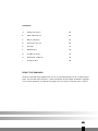
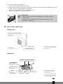
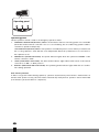
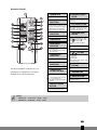
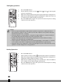
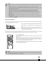
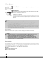
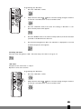
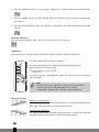
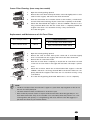
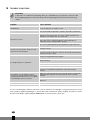
SP2035 - SP2041
6
BRUGSANVISNING
2
3
MANUEL D'UTILISATION
22
FIN
KÄYTTÖOHJE
42
4
OPERATING MANUAL
62
>
ISTRUZIONI D’USO
82
Dear Sir, Madam,
Congratulations on the purchase of your Zibro airconditioner. You have acquired a high
quality product that, if used responsibly, will give you many years of pleasure. Please read
these instructions for use first in order to ensure the maximum life span of your
airconditioner.
On behalf of the manufacturer, we provide a 24-month guarantee on all material and
production defects. Please enjoy your airconditioner.
Yours sincerely,
PVG International b.v.
Customer service department
1. READ THE DIRECTIONS FOR USE FIRST.
2. IN CASE OF ANY DOUBT, CONTACT YOUR DEALER.
4
62
CONTENTS
A
Safety instructions
64
B
Parts and functions
65
C
Before operation
68
D
Instructions for use
69
E
Air filter
75
F
Maintenance
76
G
Trouble shooting
78
H
Guarantee conditions
79
I
Technical data
80
READ THIS MANUAL
Inside you will find many helpful hints on how to use and maintain your air conditioner properly. You will find many answers to common problems in the chapter Troubleshooting Tips.
If you review chapter K “Troubleshooting Tips” first, you may not need to call for service.
4
63
A
SAFETY INSTRUCTIONS
Install the device only when it complies with local regulations, by-laws and standards. The unit is only sui-
G
table for use in dry locations, indoors. Check the mains voltage and frequency. This unit is only suitable for
earthed sockets, connection voltage 220 - 240 V. / 50 Hz.
IMPORTANT
• The device MUST always have an earthed connection. If the power supply is not earthed, you
may not connect the unit. The plug must always be easily accessible when the unit is connected.
Read these instructions carefully and follow the instructions.
• The airconditioner contains a refrigerant and can be classified as pressurized equipment.
Therefore always contact an authorized installation specialist for installation and maintenance
of the airconditioner. It is to be advised that the airconditioner is inspected and serviced on an
annual base by an authorized airconditioning engineer.
Before connecting the unit, check the following:
•
The voltage supply must correspond with the mains voltage stated on the rating label.
•
The socket and power supply must be suitable for the current stated on the rating label.
•
The plug on the cable of the device must fit into the wall socket.
•
The device must be placed and mounted on a stable surface.
The electricity supply to the device must be checked by a recognised professional if you have any doubts
regarding the compatibility.
•
•
•
•
•
•
•
•
•
•
•
•
•
•
•
•
•
•
•
•
•
This device is manufactured according to CE safety standards. Nevertheless, you must take care, as with
any other electrical device.
Do not cover the air inlet and outlet grill.
Never allow the device to come into contact with chemicals.
Never spray the unit with or submerge in water
Do not insert hands, fingers or objects into the openings of the unit.
Never use an extension cable to connect the device to the electric power supply. If there is no suitable,
earthed wall socket available, have one installed by a recognised electrician.
For safety reasons take care when children are in the surrounding of the device, as with any other electrical device.
Have any repairs and/or maintenance only carried out by a recognised service engineer or your recognised
Zibro supplier. Follow the instructions for use and maintenance as indicated in the user manual of this device.
Always remove the plug of the unit from the wall socket when it is not in use.
A damaged power cord or plug must always be replaced by a recognised electrician or your supplier.
Do not operate or stop the airconditioner by inserting or pulling out the power plug. Only use the dedicated buttons on the airconditioner or on the remote control.
Do not open the airconditioner when it is in operation. Always pull out the electrical plug when opening the device.
Always pull out the electrical plug when cleaning or servicing the airconditioner.
Do not place gas burners, ovens and/or stoves in the airstream.
Do not operate the buttons or touch the airconditioner with wet hands.
Note that the outdoor unit produces sound when in use, this could interfere with local legislation, it is the
responsibility of the user to check and to make sure the equipment is in full compliance with local legislation.
It is advised to stay out of the direct airstream.
Never drink the drain water from the airconditioner.
Do not use for the purpose of storage of food, art work or precise equipment or breeding cultivation.
When abnormality such as burnt-smell found, immediately stop the operation button and contact sales shop.
Check proper installation of the drainage securely.
4
64
Do not install in the following places:
•
Heat or steam is generated in the vicinity.
•
Under influence by the atmosphere containing in excess salt (in coastal area), sulphide gas (in spa),
ammonia, steam of high temperature and vapor.
•
Air flow from outlet is blocked, for example by snow.
•
Where oil is dispersed or oil fumes hang over.
G
B
ATTENTION!
• Never use the device with a damaged power cord, plug, cabinet or
control panel.
• Failing to follow the instructions may lead to nullification of the
guarantee on this device.
PARTS AND FUNCTIONS
Outdoor unit
Pipe and connecting cable **
Air inlet
Drain hose
Air outlet *
Earthing terminal
*
Warm air comes out when cooling,
cool air comes out when heating.
** Not included
Indoor unit
Air Inlet grill
Mold-proof Air Filters
* two on each side
Photo-Catalytic
Anti-Odor Filters
* two on each side
Static, Catechin Filters
* two on each side
Remote
Signal
Receiver
Horizontal
louver***
Vertical
louver***
Air outlet
*** The air flow direction can be
adjusted with the vertical and
horizontal louvers.
-
Beeping sound assures successfull
signal transmission between wireless remote and the indoor unit.
4
65
Operating panel
/ POWER
Operating panel
The test operation switch is used as an emergency operation switch.
1.
EMERGENCY OPERATION (MANUAL) SWITCH. If the wireless remote controlling system is not available
(when the wireless remote controller is lost or is out of battery), the air conditioning system is able to
continue its operation temporarily.
TEST OPERATION (MANUAL)SWITCH. Test operation is needed in special occasion when you need to test
the “cooling operation” even with the room temperature below 16°C, therefore it is not for the normal operation at all.
2.
POWER/ELECT (POWER INDICATOR). The power indicator lights when the operational ON/OFF of the
remote controller is “ON”.
3.
TIMER (TIMER MODE INDICATOR). The timer mode indicator lights when timer switch of the remote
controller is in “ON” or “OFF” position.
4.
OPERATE (OPERATING MODE INDICATOR). The operating mode indicator lights when the air conditioner is being operated.
Auto recovery function
lf there is any power failure during operation, operation status before power failure is memorized. 3~4
minutes after power recovery, the unit restarts automatically with previous operation status memorized
(3~4 minutes is protective time for compressor).
4
66
Remote Control
1 TRANSMITTER
Sends signals to the receiver of the indoor
unit.
*
2 FAN SPEED
INDICATION
Indicates the fan speed selected by the fan
speed button. When set at “AUTO”, the fan
speed changes automatically according to
the difference between the designated
temperature and the room temperature.
3 OPERATION MODE
INDICATION
Indicates the current operating mode.
4 TIME DISPLAY
Indicates the present time or the timer.
5 TIMER MODE
INDICATOR
ON: The air conditioner starts operation at
the designated time.
OFF: The air conditioner stops operation at
the designated time.
6 TEMPERATURE
INDICATION
Indicates the temperature set by the temperature setting buttons.
7 TRANSMITTING
INDICATION
Lights up when a signal is sent.
The above example of indications is for
the purpose of explanation only and is
different from actual indications.
8 TEMPERATURE
SETTING BUTTONS
The setting temperature increases
by 1°C (1.8°F) per press.
The setting temperature decreases
by 1°C (1.8°F) per press.
Holding a button changes the temperature
setting quickly.
j HORIZONTAL LOUVER
BUTTON
Air flow direction can be changed horizontally with swing movement (right and left)
by each press.
k FAN SPEED BUTTON
Use to adjust the fan speed. The indication
of the fa speed varies among “L” (Low),
“M” (Medium), “H” (High), and “AUTO”
each time the button is pressed.
l OPERATION MODE
BUTTON
Use to change the operating mode. The
indication of the operating mode varies
(Automatic), (Cooling),
among
(Dry), (Circulating) and
(Heating) each time the button is
pressed.*
m TIME ADJ BUTTON
Press the “TIME ADJ” button to adjust the
present time or the timer.
n
,
BUTTONS
Press these buttons to adjust the present
time or the timer.
Forward time
Backward time
Holding a button changes the time setting
in 10-minute intervals.
o TIMER FIXING
BUTTONS
Press these buttons to turn the timer ON or
OFF.
p SLEEP BUTTON
Press this button for the Sleep setting.
q ON/OFF BUTTON
Starts operation with a press: stops operation with the next press.
9 VERTICAL LOUVER
BUTTON
G
Air flow direction can be changed vertically
(upward and downward) by each press.
NOTE
• 00:00 A.M. – 12:00 A.M. = 00:00 – 12:00
• 00:00 P.M. – 12:00 P.M. = 12:00 – 24:00
4
67
C
BEFORE OPERATION
1. Operating the Remote Controller
Install / Replace Batteries
Use two dry alkaline batteries (AAA/LR03).
Do not use rechargeable batteries.
1.
Remove the battery cover on the back of the Remote Control by pulling it
according to the arrow direction shown on the cover.
2.
G
Insert new batteries making sure that the (+) and (-) of battery are installed
correctly.
3.
Reattach the cover by sliding it back into position.
NOTE!
• When replacing batteries, do not use old batteries or a different type battery. This may cause
the remote controller to malfunction.
• If you do not use the remote controller for several weeks remove the batteries. Otherwise
battery leakage may damage the remote controller.
• The average battery life under normal use is about 6 months.
• Replace the batteries when there is no answering beep from the indoor unit or if the
Transmission Indicator light fails to appear.
• Never mix new and old batteries. Never use different battery types (e.g. alkaline and
manganese dioxide) simultaneously.
Storage of the remote control and tips for use
The remote control can be placed in the wall-mounted holder. The wall-mounted holder is delivered together with the unit.
Using the remote control
Point the remote control at the receiver on the indoor unit of the air conditioner. The air conditioner can
be operated in this manner up to a distance of approximately 7 meters.
G
2. Attaching filters
4
68
COMMENT
• Never use the airconditioner without the air filter.
• Only use suitable Zibro filters. This will prevent damage to your airconditioner.
• Suitable filter packages are available at your dealer.
How to attach the air clean filters
a. Open the front panel by pulling upward
b. Remove the outer air filters. Push up the center tab of each filter slightly until
it is released from the stopper, and remove the filter downward.
Air filters
G
c.
Attach the air clean filters. Attach both “Static, catechin filters” and“Photo-
Catalytic Anti-Odor filters” on both sides.
Static,
Catechin
filters
Photo-Catalytic
Anti-Odor filters
CAUTION
Do not touch the metalic parts to avoid injury, when attaching filters.
d. Attach the air filters. Attach the air filters behind the stopper so that the
“FRONT” indication is showing outward. Make sure that the filters are completely behind the stoppers. If the filters are not attached correctly, it may
cause defects.
Air filters
e. Close the front panel by pushing downward.
D
INSTRUCTIONS FOR USE
Present time setting
Example: Set to 3:50 p.m.
1.
Press the “TIME ADJ” button once.
2.
Adjust the time with “+”, “-“ buttons. Holding a button changes time setting in 10-minute intervals.
3.
Press the “TIME ADJ” button 3 times. The present time appears on the display. The setting is complete.
G
NOTE
Even if the actual time is not programmed, you can use all operations
except “Timer operation”.
4
69
Cooling/dry operation
1.
Press the ON/OFF button
2.
Set the operation mode to Cooling
, Heating
or Dry
, by pressing the
operation mode button
3.
Adjust the setting temperature by pressing the temperature setting buttons.
4.
Adjust the fan speed by pressing the fan speed button. When the mode is set
at “AUTO” the fan speed changes automatically.
5.
Press the ON/OFF button again. The system will retain the previous setting
conditions until next operation.
G
NOTE!
• Even if you press the ON button right after the operation stop, the air conditioner will not
start operation for approx. 3 min. in order to protect the compressor. The operation will start
automatically after 3 min. of waiting.
• If the unit operates cooling and dry for a long time in high humidity (i.e., windows and doors
are opened), dew and water droplets may form on the indoor unit.
• Use dry mode when both indoor and outdoor temperatures are 16°C and above. The dry
operation may stop under the low temperature.
• In dry mode the set temperature may not be attained depending on the number of occupants,
room condition, and outdoor temperature, because dehumidification is given priority.
• Temporary vapor from condensation on the heat exchanger may form a mist at the start of dry
operation or at the change from cooling operation.
Heating Operation
1.
Press the ON/OFF button
2.
Set the operation mode to Heating
3.
Adjust the setting temperature by pressing the temperature setting buttons.
, by pressing the operation mode button.
Temperature setting range:16~30°C by 1°C step.
4.
Adjust the fan speed by pressing the fan speed button. When the MODE is
set at “AUTO”, the fan speed changes automatically.
5.
Press the ON/OFF button again.The system will retain the previous setting
conditions until next operation.
4
70
G
NOTE!
• The air will not flow out unless the heat exchanger gets warm enough in order to prevent cold
air.
• The air conditioner will not start operation for approx. 3 min. in order to protect the
compressor even if you press the ON button right after the operation stops. The operation will
start automatically in 3 min.
• The outdoor unit may frost and heating capacity may deteriorate during the heating
operation. In such case, the unit automatically stops heating operation and conducts
defrosting operation. The fans of the indoor and outdoor units stop during the defrosting
operation.
• We recommend you change the fan speed mode to “Auto” from “High” if you don’t feel
warm enough.
• We suggest you use additional heating equipment if it is difficult to warm the room because of
low outdoor temperature.
Automatic operation
In automatic operation the air conditioner selects the operation mode (cooling, dry, heating) according to
the room temperature when it starts.
• The air conditioner will restart in the previous mode if auto-
Room temperature
matic operation is resumed within 3 hours from the switchHeating
Operation
Cooling Operation
off.
Dry
Operation
• Mode review. The computer checks and compares the room
Outdoor Temperature
temperature regularly after the compressor shuts off, and
will adapt the operating mode.
The operation mode, automatically selected when the unit starts, will be reselected after the room temperature reaches the setting temperature and the outdoor unit stops for 15 minutes or longer.
1.
Press the ON/OFF button
2.
Set the operation mode to Automatic “AUTO“, by pressing the operation
mode button
3.
Adjust the setting temperature by pressing the temperature setting buttons.
4.
Adjust the fan speed by pressing the fan speed button. When the mode is set
at “AUTO” the fan speed changes automatically.
5.
Press the ON/OFF button again.The system will retain the previous setting
conditions until next operation.
G
NOTE
If the selected mode by Automatic operation does not suit you, set the operation mode (cooling,
dry, heating) with the operation mode button.
4
71
Air flow adjustment
Standard Position
Approx. 10 degrees
(Cooling/Dry)
Approx. 70 degrees
(Heating)
The vertical louver will move automatically to the suitable position when ON/OFF
Level
Swing of Air Flow
Level
Approx. 10
degrees
Cooling
Dry
Heating
Approx. 40
degrees
Approx. 45
degrees
Approx. 70
degrees
G
NOTE!
G
NOTE!
Vertical adjustment
button is pressed.
Swing of air flow
The vertical louver will keep moving within the range illustrated on the right, if
the vertical louver button is pressed once.
Fixing the air flow Direction
The vertical louver will come to a halt if the vertical louver button is pressed once
again. The vertical louver will be set at previous position automatically for the next
operation.
• The vertical louver closes the outlet automatically when the unit is switched off.
• Do not keep the vertical louver downward for a long time during cooling or dry operation.
Otherwise dew drops may appear at the outlet.
• The angle of vertical and horizontal louvers may automatically change to prevent
condensation during cooling operation.
• Use the wireless remote control unit to change the angle of the vertical louver. Do not force to
move it by hands as it may make the louver not work correctly. Stop the operation once and
turn on again if the louver doesn’t work correctly.
Swing of Air Flow
The horizontal airflow can be adjusted by manually changing the horizontal louver blades.
• Dew drops may appear at the outlet under high humidity (e.g.during rainy season) if the
system is operated with the horizontal louver faced to the extreme right or left.
• Use the wireless remote control unit to change the angle of the horizontal louver. The
horizontal louver may move out of the normal range if forced by hands. Unplug in order to
initialize the setting if you encounter problems.
Timer operation
Before setting the timer, confirm that the present time is set accurately. Once you set the timer, the remote
controller memorizes the setting. From the next time, you can operate the same timer mode just by pressing the ON/OFF button and the Timer fixing (“ON/OFF Timer”) button.
You can use the combined function of the “ON Timer” and “OFF Timer”.
“ON Timer”
Example: set the “ON Timer” to 7 a.m.
Operation starts at the set time.
4
72
Programming the “ON Time”
1.
Press the “TIME ADJ” 2 times.
2.
Adjust the time with the
button. The time setting changes in 10-minu-
te intervals. Hold the button to fast forward the time.
3.
Press the “TIME ADJ” button two times. The setting of “ON Time” is complete and the present time appears.
4.
Press the “ON/OFF” button. Proceed from Step 5 (below) if the unit has been
operated or the OFF Timer has been set.
5.
Press the timer fixing button “ON”. The “ON Time” is displayed for 2 seconds
and then the present time appears.
Cancelling “ON Timer”
Press the Timer fixing button “ON”. The timer lamp of the indoor unit goes off.
“OFF Timer”
Example: Set the “Off Timer” to 10 p.m.
Operation starts at the set time.
Programming the “OFF Time”
1.
2.
Press the “TIME ADJ” 3 times.
Adjust the time with the
button. The time setting changes in 10-minu-
te intervals. Hold the button to fast forward the time.
4
73
3.
Press the “TIME ADJ” button once. The setting of “OFF Time” is complete and the present time appears.
4.
Press the “ON/OFF” button. Proceed from Step 5 (below) if the unit has been operated or the ON Timer
has been set.
5.
Press the timer fixing button “ON”. The “ON Time” is displayed for 2 seconds and then the present time
appears.
Cancelling “OFF Timer”
Press the timer fixing button “OFF”. The timer lamp of the indoor unit goes off.
“SLEEP Timer”
Pressing this button starts the timer mode that will stop the operation after the setting time.
Press the “SLEEP” button during the operation.
The setting time repeats the following mode by pressing the button:
G
Continuous operation (Sleep Operation: OFF). The operation stops after passing
the setting time.
NOTE
• When you select both “OFF Timer” operation and “Sleep Timer”
operation, the latest setting precedes the first setting.
• “Sleep Timer” operation has no need to set the present time.
Sleep Timer features
During Cooling Operation
The setting temperature rises 0.6°C after 30 minutes of Sleep Timer ON, and rises
0.6°C again after 30 minutes of the first temperature rise.
During Heating Operation
The setting temperature drops 0.6°C after 30 minutes of Sleep Timer ON, and
drops 0.6°C again after 30 minutes of the first temperature drop.
4
74
Emergency and test operation
Emergency Operation
•
The emergency operation is needed only when the remote control can not be used.
•
When you press the Emergency Operation Switch, you will hear a beep and the emergency operation
starts.
•
Emergency operation is preset for the following two modes, only based on the temperature of the
room at the time of operation.
Temperature
Operation
mode
Designated
temperature
Timer mode
Air flow
Above 23°C
Cooling
26°C
Continuous
Automatic
Heating
23°C
Continuous
Automatic
G
Below 23°C
NOTE
Emergency operation at the temperature between above 23°C and below 26°C just switch the
machine in operation in “cooling mode” without actually “cooling”. It is not possible to operate
in “Dry” mode.
Test operation
•
Same switch as used in Emergency operation.
•
Test operation is needed in special occasion when you need to test the “cooling operation” even with
the room temperature below 16°C, therefore it is not for the normal operation at all.
•
Press the Emergency operation switch and hear the beep once, then keep on pressing the switch for
more than 5 seconds but no more than 10 seconds. After the first 5 seconds you will hear two beeps
then release the switch and you will have the Test Operation Mode.
•
The Test Operation Mode will run the air conditioner at “cooling” with air flow speed at “Hi” for 30
minutes and stops automatically.
Termination of emergency or test operation
•
You can terminate the operation when you hear a beep by either pressing the switch once more, or by
operating through remote control.
•
When you operate through remote control, is automatically get back to just normal operation mode by
remote control.
E
AIR FILTER
This air conditioner is equipped with 3 filter types to clean the circulated room air.
a.
Mold-Proof screen filter; the screen filter removes dust particles from the air. The surface of the screen
filter is mold proof which prevents mold from growing, and thus delivers clean, fresh air from the airconditioner.
b.
Photocatalytic Anti-odor Filter; to remove odours.
c.
Static Catechin Filter; Inhibiting proliferation of viruses and germs.
4
75
The filter frame on the backside of the unit can be opened. The Mold-Proof screen filter, the Photo-catalytic Anti-odor Filter and the Static Catechin Filter can be installed or removed.
a.
The Mold-Proof screen filter has to be cleaned regularly with a vacuum cleaner to avoid blocking of the
air flow. Alternatively take out the filter and wash it with water. After washing, dry the filter completely in the shade.
b.
The Photocatalytic Anti-odor Filter can be recharged by placing it into direct sunlight for 6 hours per
half year. The presence of smoke, etc can shorten the lifetime. Expected lifetime under normal circumstances 2~3 years
G
c.
The Static Catechin Filter; can be cleaned with a vacuum cleaner when dusty but has to be changed at
the expected lifetime under normal circumstances after approximately 1 year.
G
F
G
NOTE
• The old filters can be disposed in the ‘Non-biological garbage container’.
• Replacement filter packages are available at your dealer.
• To run the unit without Mold-Proof filter, Photocatalytic Anti-odor Filter or Static Catechin
filter does not bring any harm to the airconditioner. In that case odours and airborne micro
organisms are not removed from the circulated air.
NOTE
The Photocatalytic Anti-odor Filter and the Static Catechin filter are delivered in a separate plastic
packaging. Remove plastic bags and install filters (refer chapter B).
MAINTENANCE
WARNING!
Before maintenance, be sure to turn off the system and the circuit breaker.
Remote controller
Do not use water, wipe the controller with a dry cloth. Do not use glass cleaner or chemical cloth.
Indoor body
Wipe the air conditioner by using a soft and dry cloth. For serious stains, use a neutral detergent diluted
with water. Wring the water out of the cloth before wiping, then wipe off the detergent completely.
Do not use the following for cleaning.
Gasoline, benzine, thinner or cleanser may damage the coating of the unit. Hot water over 40°C (104°F) may
cause discoloring or deformation.
4
76
Screen Filter Cleaning. (once every two weeks)
1.
Open the inlet by pulling upward.
2.
Remove the screen filter. Push up the filter’s center tab slightly until it is released from the stopper, and remove the filter downward.
3.
Clean the screen filter. Use a vacuum cleaner to remove dusts, or wash the filter with water. After washing, dry the screen filter completely in the shade.
4.
Attach the filter behind the stopper so that the “FRONT” indication is showing outward. Make sure that the screen filter is completely behind the
stopper. If the filter is not attached correctly, it may cause defects.
Close the inlet grille.
Replacement and Maintenance of Air Clean Filters
Photo-Catalytic Filters
2 Pieces
Replacement Filters
Photo-Catalytic Filters Model CAC-5
Static,Catechin Filters
2 Pieces
Static, Catechin Filters Model CAC-6
1.
Open the inlet by pulling upward.
2.
Remove the outer air filters. Push up the center tab of each filter slightly
until it is released from the stopper, and remove the filter downward.
Air filters
3.
Remove the air clean filters inside.
4.
Clean the air clean filters completely or attach new air clean filters. Set each
of the new air clean filters in the right and left frame. The shape is symmetrical.
Static, Catechin
filters
Photo-Catalytic
Anti-Odor filters
5.
Attach the air filters. Attach the air filters behind the stopper so that the
“FRONT” indication is showing outward. Make sure that the filters are completely behind the stoppers.If the filters are not attached correctly, it may
cause defects.
6.
Air filters
G
Close the inlet by pushing downward. Make sure to close it completely.
NOTE
• The Photo-Catalytic filters are effective for approx. 3 years when exposing them to the sun for
6 hours once every half-year.
• The Static-Catechin filters are effective for around one year.
• Remove dust by vacuum cleaner or replace with the new filters when they get dirty. Do not
wash them with water. They are not reusable once soiled. Dirty filters may result in loss of air
cleaning effect and capacity of cooling/heating, and cause offensive odor. We suggest you
purchase new filters at your nearest dealers.
4
77
G
G
TROUBLE SHOOTING
CAUTION!
In the event of a malfunction (burning smell, etc.) immediately stop operation, disconnect the
Power Supply plug and consult sales shop. Before requesting service, perform the following
checks:
Problem
Cause / Solution
The system does not start re-operation
immediately.
This is for protection of the system. After a stop, the sys-tem does
not start operation for approx. 3 min
Smells are generated.
This is because the system circulates smells from the interior air
such as the smell of cigarettes, cosmetics, the walls or furniture.
When cooling is started or heating is stopped, a swishing or a
gurling noise may be heard. This noise is generated while the
refrigerant is flowing in the air conditioner.
Occurring of noise.
When starting or stopping operation, a cracking noise may be
heard. This noise is generated by the casing expanding or
shrinking because of temperature changes.
A whooshing noise may be heard during operation of the system.
This noise is generated when the refrigerant changes direction.
Air does not flow (Indoor Unit). Air flow
speed can not be changed.
During the dry mode operation, air may not flow out, to prevent
excessive cooling.
During the heating operation, air does not flow out until the air
is heated enough to prevent cold air flow. During the thawing in
heating, air may not flow.
The cooling/heating function may not work effectively when the
air filter is clogged with dust and dirt.
Make sure the room temperature has not yet reached the
designated level.
Cooling/heating is not sufficient.
Make sure the air flow speed is not set at ”LO“.
Make sure the inlet or outlet of the outdoor unit is not blocked.
When the room temperature has not reached the required level
because of low ambient temperature, add other heating
facilities.
The indicator on the wireless remote
controller is dim.The indicator dims when
sending signals.Indication does not appear
on the wireless remote controller.
Make sure if the dry batteries have enough charge. Use dry R-03
(AAA) batteries. Replace worn dry batteries with a new pair
batteries.
Make sure the dry batteries are set in the right polarity
directions.
Misting (Indoor Unit)
It is caused by chilled air in cooling operation.
Steaming (Outdoor Unit)
It is caused by defrosting of outdoor unit in heating operation.
In case of an emergency while in operation, such as malfunction, stoppage or unoperative remote control
unit caused by lightning damage or automobile radio transmitter, please unplug and wait for three
minutes. Then plug in again and push ON/OFF button on the remote control unit.
4
78
H
GUARANTEE CONDITIONS
The air conditioner is supplied with a 24-month guarantee, commencing on the date of purchase. All material and manufacturing defects will be repaired or replaced free of charge within this period. The following
rules apply:
1.
We expressly refuse all further damage claims, including claims for collateral damage.
2.
Repairs to or replacement of components within the guarantee period will not result in an extension
of the guarantee.
3.
The guarantee is invalidated if any modifications have been made, non genuine parts are fitted or
repairs are carried out by third parties.
4.
Components subject to normal wear, such as the filter, are not covered by the guarantee.
5.
The guarantee is valid only when you present the original, dated purchase invoice and if no modifications have been made.
6.
The guarantee is invalid for damage caused by neglect or by actions that deviate from those in this
instruction booklet.
7.
Transportation costs and the risks involved during the transportation of the air conditioner or air conditioner components shall always be for the account of the purchaser.
8.
Damage caused by not using suitable Zibro filters is not covered by the guarantee.
9.
Refrigerant loss and/or leakage because of incompetent (dis)connecting the units is not covered by the
guarantee conditions applicable to this product.
To prevent unnecessary expense, we recommend that you always first carefully consult the instructions for
use. Take the air conditioner to your dealer for repairs if these instructions do not provide a solution.
4
79
I
TECHNICAL DATA
Model
SP 2035
SP 2041
DC inverter Wall mounted split
Type air-conditioner
850-3500 (2930)
800-4100 (3660)
Cooling capacity, min-max (nom)*
W
Cooling capacity, min-max (nom)*
BTU/h
2700-12000 (10000)
2700-14100 (12500)
W/W
4,44
4,14
EE Class*
EER*
A
700-5300 (3870)
A
700-6100 (5010)
Heating capacity, min-max (nom)*
W
Heating capacity, min-max (nom)*
BTU/h
2400-18000 (13200)
2400-20700 (17100)
W/W
5,05
4,43
Heating performance
COP*
Dehumidifying capacity ***
L / 24h
Power consumption cooling, min-max (nom)
kW
Power consumption heating, min-max (nom)
kW
Power supply
V / Hz / Ph
Current (nom.) cooling / heating
A
Max. Current
A
Air flow cooling/heating**
For rooms up to**
3
m /h
m3
Compressor type
Thermostatic range
ºC
Operating range
ºC
Controls manual / mechanic / electronic
Remote control Yes / No
r / gr
mm
Pressure suction / discharge
bar
Dimensions indoor unit (w x h x d)
mm
Dimensions outdoor unit (w x h x d)
mm
Net weight indoor unit
kg
Net weight outdoor unit
kg
Gross weight indoor unit
kg
Gross weight outdoor unit
kg
Sound pressure level indoor unit
dB(A)
Sound pressure level outdoor unit
dB(A)
Unit protection indoor
IP
Unit protection outdoor
IP
Fuse rating
*
Conform EN 14511-2004
**
To be used as indication
***
Moisture removal at 27°C, 60% RH
0,16-0,93 (0,66)
A
38
0,16-0,93 (0,89)
0,16-1,26 (0,77)
0,16-1,26 (1,13)
2,9/3,4
3,9/5,0
230 / 50 / 1
7,7
540/660
230 / 50 / 1
7,7
570/750
85-110
100-120
Rotary
Rotary
16 - 30
3
16 - 30
-15 / 43
-15 / 43
Electronic remote
Electronic remote
Y
Y
Screen dust, Photocatelytic anti odor, Static Catechin
Air filter type(s)
Refrigerant pipe diameter Liquid - Gas
38
3
Fan speeds
Refrigerant type / charge
A
R410a / 1100
6,35 / 9,52
11/41
R410a / 1100
6,35 / 9,52
11/41
799x295x210
799x295x210
9,5
9,5
780x550x278
35
13
38
780x550x278
35
13
38
25-43
25-43
IPX0
IPX0
T3,15A / 250V
T3,15A / 250V
42
IPX4
42
IPX4
Waste electrical products should not be disposed with household waste. Please recycle where facilities exist. Check with your local authority or retailer for recycling advice.
Environmental information: This equipment contains fluorinated greenhouse gases covered by the Kyoto
Protocol. It should only be serviced or dismantled by professional trained personnel.
This equipment contains R410a refrigerant in the amount as stated in the table above. Do not vent R410a
into atmosphere: R410a, is a fluorinated greenhouse gas with a Global Warming Potential (GWP) = 1975
4
80
4
81
e BELGIË
PVG Belgium NV/SA
Industrielaan 55
2900 SCHOTEN
tel:
+32 3 326 39 39
fax:
+32 3 326 26 39
email: [email protected]
> ITALIA
PVG Italy SRL
Via Niccolò Copernico 5
50051 CASTELFIORENTINO (FI)
+39 571 628 500
tel:
fax:
+39 571 628 504
email: [email protected]
q SCHWEIZ
PVG Schweiz AG
Salinenstrasse 63
4133 PRATTELN
tel:
+41 61 337 26 51
fax:
+41 61 337 26 78
email: [email protected]
u NORGE
Appliance Norge AS
Vogellunden 31
1394 NESBRU
tel:
+47 667 76 200
fax:
+47 667 76 201
email: [email protected]
2 DEUTSCHLAND
PVG Deutschland GmbH
Siemensstrasse 31
47533 KLEVE
tel:
0800 - 9427646
fax:
+31 (0)412 648 385
email: [email protected]
1 NEDERLAND
PVG International B.V.
P.O. Box 96
5340 AB OSS
tel:
+31 412 694 694
fax:
+31 412 622 893
email: [email protected]
6 DANMARK
Appliance A/S
Blovstroed Teglvaerksvej 3
DK-3450 ALLEROED
tel:
+45 70 205 701
fax:
+45 70 208 701
email: [email protected]
9 PORTUGAL
Gardena, Lda
Recta da Granja do Marquês
ALGUEIRÃO
2725-596 MEM MARTINS
tel:
+ 35 21 92 28 530
fax:
+ 35 21 92 28 536
email: [email protected]
5 ESPAÑA
PVG España S.A.
Pol. Ind. San José de Valderas II
Comunidad ”La Alameda”
C/ Aurora Boreal, 19
28918 LEGANÉS (Madrid)
tel:
+34 91 611 31 13
fax:
+34 91 612 73 04
email: [email protected]
: POLSKA
PVG Polska Sp. z. o. o.
ul. Kościelna 110
26-800 Białobrzegi
tel:
+48 48 613 00 70
+48 48 613 00 70
fax:
email: [email protected]
3 FRANCE
PVG France SARL
4, Rue Jean Sibélius
B.P. 185
76410 SOTTEVILLE SOUS LE VAL
+33 2 32 96 07 47
tel:
fax:
+33 0 820 34 64 84
email: [email protected]
F I N SUOMI
Appliance Finland Oy
Piispantilankuja 6C
02240 ESPOO
+358 9 4390 030
tel:
fax:
+358 9 4390 0320
email: [email protected]
= SVERIGE
Appliance Sweden AB
Sjögatan 6
25225 HELSINGBORG
tel:
+46 42 287 830
+46 42 145 890
fax:
email: [email protected]
y SLOVENIJA
Monteko d.o.o.
Neubergerjeva 4
1000 Ljubljana
+386 (0)1 437 1273
tel:
fax:
+386 (0)1 437 1273
email: [email protected]
T R TURKEY
PVG Is›tma Klima So¤utma Ltd.fiti.
Tepekule is merkezi
Anadolu Cad. No: 40 K:3 D:306
35010 BAYRAKLI/IZMIR
tel:
+ 90 232 461 51 01
+ 90 232 461 51 85
fax:
email: [email protected]
avg©080321
4 UNITED KINGDOM
Scott Brothers Ltd.
The Old Barn, Holly House Estate
Cranage, Middlewich, CW10 9LT UK
tel.:
+44 1606 837787
fax:
+44 1606 837757
email: [email protected]
PVG Traffic
i ÖSTERREICH
PVG Austria VertriebsgmbH
Salaberg 49
3350 HAAG
tel:
+43 7434 44867
fax:
+43 7434 44868
email:
[email protected]
man_SP2035 - SP2041
DISTRIBUTED IN EUROPE BY PVG INTERNATIONAL B.V.