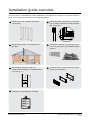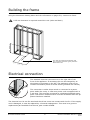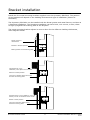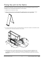
1
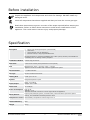
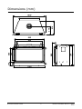
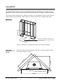
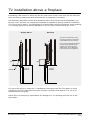
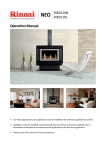
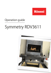
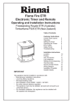
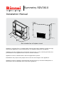
Symmetry RDV3610
Installation Manual
Not intended as a fireplace insert
Appliance (including flue) is installed after framing and before cladding. Rinnai strongly
recommend appliance is fully tested before any cladding materials are applied.
Cladding must be installed up to the flange and not over it. Any overhang will alter the
performance of the appliance and cause an unsafe situation.
Appliance must be installed with a Rinnai supplied flue system.
Installation may require two people due to the size and weight of the appliance.
Appliance must be installed, commissioned and serviced by a licensed tradesperson in
accordance will all applicable local rules and regulations.
Contents
Before installation
3
Specification
3
Dimensions
4
Location
5
Clearances
6
Mantels, surrounds, and hearths
7
TV installation above a fireplace
8
Installation guide overview
9
Building the frame
10
Electrical connection
10
Bracket installation
11
Fixing the unit to the frame
12
Flue installation - Rinnai flue kits
13
Flue installation - Rinnai flue components
15
Flue installation - 45 degree offsets
16
Flue installation - general guidelines
17
Flue installation - vertical termination
19
Flue installation - horizontal termination
21
Gas connection
22
Flue restrictor installation
23
Log set installation
24
Test pressures
26
Flame pattern
27
Cladding
28
Fitting the frames and dress guard
29
Commissioning
30
Wiring diagram
31
WARNING
Improper installation, adjustment, alteration, service or maintenance
can cause property damage, personal injury or loss of life.
For assistance or additional information contact Rinnai on
0800 RINNAI (0800 746 624).
Before installation
Unpack the appliance and components and check for damage. DO NOT install any
damaged items.
Check all components have been supplied and that you have the correct gas type.
Read these instructions to get an overview of the steps required before starting the
installation. Failure to follow these instructions could cause a malfunction of the
appliance. This could result in serious injury and property damage.
Specification
Description
•
•
•
•
Direct vent inbuilt gas fireplace (natural draft)
Glass front
Convection fan (top air discharge)
Remote control, 7-day programmable timer
Recommended for a new build installation into a false (mock) chimney. Not suitable for
retrofitting into an existing masonry fireplace.
Combustion Method
Ceramic top pan burner
Data Plate
Centre front of base panel (behind the service panels)
Flue
Balanced flue: inner = 100 mm, outer = 170 mm
Appliance must be installed with a Rinnai supplied flue system
Gas Connection
½ “ BSP male flare
Gas Type
NG and General Product LPG
Heating Area
Heats up to 100 m2
Ignition
Integrated sparker to pilot
Input/Output
Input: 19-33 MJ/h
Output: 4.2-7.5 kW
Noise Level
37-45 dB(A)
Power Consumption
High 50 W
Standby <1 W
Standard electrical connection is to the right side of the appliance
Safety Devices
Light to pilot, delayed ignition, overheat switch, electronic flame supervision (flame
failure), and combustion chamber pressure relief.
Temperature Control
Thermostatic, temperature control range 7-32 °C
Thermal Efficiency
80%
Weight
60 kg
Rinnai New Zealand Limited
3
RDV3610 Installation Manual: 11658-E
05-10
Dimensions (mm)
510
310
1090
715
149
Rinnai New Zealand Limited
750
775
845
500
400
995
890
1060
4
RDV3610 Installation Manual: 11658-E
05-10
Location
The main points governing location are flueing and warm air distribution. The heater must not
be installed where curtains or other combustible materials could come into contact with the
appliance. In some cases curtains may need restraining. Refer next page for clearance details.
The heater must be positioned on a flat level surface. For installations further up the wall, the
heater needs to be supported, either construct a base using board or support with joists.
850 mm min.
Enclosure
dimensions
.
in
m
1100
The 540 mm minimum dimension will
give a 25 mm clearance (plus) from the
back of the unit.
m
0
54
- 11
25
m
mm
A 25 mm clearance is required around the unit (sides and back).
Enclosure
dimensions in a
corner
These are the minimum dimensions required if using the width, height
and depth dimensions above.
m
m
915 mm
5
29
1
1830 mm
Rinnai New Zealand Limited
5
RDV3610 Installation Manual: 11658-E
05-10
Clearances
The appliance must not be installed where curtains or other combustible materials could come
into contact with the heater. In some cases curtains may need restraining.
The clearances listed below are minimum clearances unless otherwise stated. There are further
details on mantel and surround clearances on the next page.
Non-combu
stible
cladding
400
1000
To ceiling
Non-combu
stible
cladding
400
400
0
1
0
0
Up-wall installations
If the Symmetry is being installed up the wall and close to the ceiling, the recommended
minimum clearance is 1000 mm.
Non-combustible cladding
Non-combustible cladding such as 9 mm Eterpan MD1 (extending at least the full width of
the appliance and 400 mm in height) to be installed directly above the fire as shown. This is
required to minimise the risk of scorching or fire in the event of a power failure (fan will stop
running and hot air will rise directly above the unit).
1
9mm Eterpan MD (medium density) is supplied by PBS Ltd (www.pbs.co.nz). Other materials may also be
suitable, please seek advice from a cladding supplier as to the correct application and specification of the material.
Rinnai New Zealand Limited
6
RDV3610 Installation Manual: 11658-E
05-10
Mantels, surrounds, and hearths
B - Mantel depth
Min
Vertical
Clearance
400mm
AMinimum
- Mantel height
from
top of fireplace
D - Surround
projection
C - Surround from side of fireplace
A mantel and surround are allowed providing they are outside the minimum clearances shown
below.
A
Mantel height from top of fireplace
400 mm minimum
B
Mantel depth at 400 mm (vertical clearance)
300 mm maximum
For every 50 mm of added mantel depth, there must be an additional 100 mm of vertical clearance. For
example; a mantel depth (B) of 350 mm will require 500 mm (A) of vertical clearance.
C
Surround from side of fireplace
300 mm minimum
D
Surround projection at 300 mm (side clearance)
50 mm maximum
For every 50 mm of added surround projection, there must be an additional 50 mm of side clearance. For
example; a surround projection (D) of 100 mm will require 350 mm (C) of side clearance.
Hearths
A hearth is not necessary but can be used for decorative purposes or protection of sensitive
flooring if required. It must not obscure the front of the fire.
Rinnai New Zealand Limited
7
RDV3610 Installation Manual: 11658-E
05-10
TV installation above a fireplace
If installing a flat screen TV above the fire the main issue is heat. Heat from the fire and heat
from the flueing components that sit behind the TV, especially if recessed.
The Symmetry RDV3610 has fan that distributes warm air from the top of the appliance out
into the room. As warm air is dispersed outwards as opposed to directly upwards, installation
of a TV may be an option. The following are recommended minimum clearances when installing
a TV directly above the Symmetry RDV3610 or into a recess. All dimensions are in mm.
Directly Above
Recessed
75
The 400 mm dimension is the
minimum clearance required to
combustibles and to a mantel.
20
Flue
TV
TV
Flue
For a TV mounted directly above
the Symmetry RDV3610, the
mantel must be at least the
depth of the TV to deflect the
heat away from the appliance.
400
400
220
Mantel
Rinnai
DV3610
Rinnai
DV3610
It is up to the owner to check the TV installation instructions with the TV supplier to verify
clearances. Some TV manufacturers have warranty conditions that state a TV is not to be
installed above a fireplace.
Rinnai does not accept any responsibility for damage to a TV resulting from the use of this
information.
Rinnai New Zealand Limited
8
RDV3610 Installation Manual: 11658-E
05-10
Installation guide overview
This overview is intended to provide installation information at a high level. Further detail on
each of the steps are provided in the following pages.
Build frame and complete electrical
connection.
Install brackets, Symmetry unit and fix
unit to frame. Install flue and complete
gas connection.
Install ducting kit (if purchased) and
gas pipe.
Install flue restrictor (if required), log
set, test pressures and establish flame
pattern.
Fit cladding, ensuring that noncombustible cladding is installed above
the unit (p. 7).
Fit inner frame, outer frame and mesh
guard (if purchased)
Complete commissioning checklist.
Rinnai New Zealand Limited
9
RDV3610 Installation Manual: 11658-E
05-10
Building the frame
Using the dimension drawing below and the information on pages 5-8, construct a frame.
A 25 mm clearance is required around the unit (sides and back).
850 mm min.
IMPORTANT
.
in
m
1100
40
m
m
The 540 mm minimum dimension will
give a 25 mm clearance (plus) from the
back of the unit.
5
- 11
25 m
m
Electrical connection
25
0m
m
The standard electrical connection is to the right side of the
front of the appliance. If necessary this can be changed by an
electrician to terminate on the left. The appliance must not be
located immediately below a socket outlet (potential fire hazard).
The connection is either direct wired or connected to a power
point within the cavity. A 1500 mm power cord is supplied with a
3-pin plug. This must be connected to a dedicated earthed power
point. The electric isolation switch must be accessible after the appliance has been installed.
The electrical cord is not fire rated and should not come into contact with the fire. If the supply
cord is damaged, it must be replaced by a licensed tradesperson. This must be a genuine
replacement part available from Rinnai, part number 6765B.
Rinnai New Zealand Limited
10
RDV3610 Installation Manual: 11658-E
05-10
Bracket installation
Install the four metal mounting brackets supplied onto the Symmetry RDV3610. The position
of the brackets will depend on the cladding thickness and type of installation (framed or
frameless).
The Symmetry RDV3610 can be installed with the Rinnai granite and metal frames, and also as
a frameless installation. The frameless installation can have brick, rock veneer, or tiles, these
sit tight up against the framing plate of the fireplace.
The metal mounting bracket adjusts 20 mm to allow for the different cladding thicknesses,
refer diagrams below.
Rinnai granite or
metal frame
Bracket in forward position
Backing board around framing plate
Frameless brick or tile
installation, note depth of brick recess
Bracket in middle position
Front face of backing board level with
back face of framing plate
Frameless brick or tile installation, note
cutaway in brick for shallower brick recess
Bracket in back position
Front face of backing board sitting
behind the framing plate
Rinnai New Zealand Limited
11
RDV3610 Installation Manual: 11658-E
05-10
Fixing the unit to the frame
The Symmetry RDV3610 comes pre-assembled with the burner already in position. For all
installations the unit MUST BE positioned on a level surface.
1. Position the unit inside the cavity.
2. Bend and secure the two metal stand-offs supplied with the unit into position. These
provide the required 150 mm minimum vertical clearance to the upper lintel.
3. Fix unit to frame with the four mounting brackets. These act as seismic constraints as well
as providing the horizontal clearance to the frame.
4. Install glass front, this will help protect the unit while the remaining installation work
is completed. The carton in which the Symmetry is packaged has a cardboard cut-out
that is the same size as the glass frame. This can also be used to protect the unit during
installation.
Rinnai New Zealand Limited
12
RDV3610 Installation Manual: 11658-E
05-10
Flue installation - Rinnai flue kits
Rinnai Symmetry RDV3610 flue kits have been based on the flue configurations shown. If you
have a combined vertical and horizontal flue configuration you can order separate components
to suit.
Vertical Flue
Horizontal Flue
Roof cowl (high wind)
Flue pipe short (1 x 300 mm) or
Flue pipe long (2 x 230 mm)
Wall terminal (square)
90 ° elbow
Flashing collar
Flashing box
Horizontal flashing kit
Flue pipe 600 mm
Wall strap
Flue pipe 1.2 m
RDV3610 Flue Kit Horizontal
A (short, R3660)
Contains:
•
•
•
•
•
•
Flue pipe 600 mm
Elbow 90 °
Flue pipe 300 mm
Wall thimble
Flashing
Wall terminal
x
x
x
x
x
x
1
1
1
1
1
1
Flue Kit Vertical 3.6 m
(R3665)
RDV3610 Flue Kit Horizontal
B (long, R3661)
Contains:
Contains:
•
•
•
•
•
•
Flue pipe 600 mm
Elbow 90 °
Flue pipe 230 mm
Wall thimble
Flashing kit
Wall terminal
Rinnai New Zealand Limited
x
x
x
x
x
x
•
•
•
1
1
2
1
1
1
13
Flue pipe 1.2 m
x3
Wall strap
x2
Roof cowl (high wind)x 1
RDV3610 Installation Manual: 11658-E
05-10
Flue installation - Rinnai flue kits
Symmetry RDV3610 horizontal flue kits and dimensions
The following diagram explains the components, dimensions (mm) and appropriate flue kits
available for differing horizontal flue installations. Refer to the 'Distance from Appliance to the
Cowl' table to calculate what flue pipe length and/or kit you may need.
RDV3610 Long Horizontal Flue Kit B (R3661)
RDV3610 Short Horizontal Flue Kit A (R3660)
D
D
325-440
310
310
435-550
90� Elbow
230 mm Pipe x 2
740
Cowl
1475
Flashing Kit
300 mm Pipe
Interior wall
600 mm Pipe
Base
25
540
Distance from the appliance to the cowl
Horizontal Flue
D
Kit A
300 mm Pipe
635
750
Kit B
230 mm Pipe x 2
745
860
300 mm + 230 mm Pipe
825
940
300 mm Pipe x 2
895
1010
Rinnai New Zealand Limited
•
Adjust the distance by sliding the cowl on the pipe
•
At its maximum position, the cowl should still keep a 45
mm overlap
14
RDV3610 Installation Manual: 11658-E
05-10
Flue installation - Rinnai flue components
RDV3610 Flue Elbow 90°
Bend (R3643)
RDV3610 Flue Elbow 45°
Bend (R3642)
Bends - effective length
Once joined effective length
reduces 35 mm:
108
•
•
90°= 130 mm
45°= 73 mm
108
165
165
Used to facilitate vertical
and horizontal flueing. Elbow
swivels 360 ° at base. Angle not
adjustable.
Offsets obstructions as needed.
Elbow swivels 360 ° at base.
Angle not adjustable. Comes
packaged as a set of two.
Wall Terminal
(R3650)
Flue terminal required for
all horizontal installations
(aluminium).
RDV3610 Flue Pipes
Roof Cowl
(R3651)
Flue terminal required for all
vertical installations (aluminium).
Flue Pipes - effective length
Horizontal Flashing Kit
(R3646)
Flashing components used to
join internal flue to outside flue
terminal (to provide a weathertight seal) in horizontal flue
installations.
RDV3610 Flue Extension
Once joined nominal length
reduces 35 mm:
150
230
300
450
mm
mm
mm
mm
(R3630)
(R3631)
(R3632)
(R3633)
600 mm (R3634)
900 mm (R3635)
1.2 m (R3636)
•
•
•
•
•
•
•
Nominal
150 mm
230 mm
300 mm
450 mm
600 mm
900 mm
1200 mm
=
=
=
=
=
=
=
Effective
117 mm
194 mm
270 mm
422 mm
575 mm
879 mm
1184 mm
Pipe used to construct horizontal
and vertical flueing (cannot be cut
to size).
Effective lengths are variable
(from 35 mm) due to rounding of
the flue pipe dimensions.
Wall Strap
(adjustable, R3647)
Flue Elbow Strap
(R3644)
Used in interior/exterior
installations to add lateral
support to the flue. Provides
a 50-200 mm clearance to
combustible walls.
Rinnai New Zealand Limited
Used to prevent excessive
weight on the flue elbow.
15
75-175 mm (R3638)
75-360 mm (R3639)
Used for extending straight
lengths of flue. Available in two
lengths (extending to 175 or
360 mm)
Flue Restrictor
(supplied, 11516)
For vertical installations
greater than 2.3 m. Maintains
efficiency by restricting air
flow through the unit as flue
length (flue pull) increases.
RDV3610 Installation Manual: 11658-E
05-10
Flue installation - 45 degree offsets
Flue pipe (length and code)
Offset (mm)
Rise (mm)
None (bend to bend)
N/A
124
340
150 mm
R3630
203
419
230 mm
R3631
257
473
300 mm
R3632
311
527
450 mm
R3633
417
633
600 mm
R3684
524
740
1.2 m
R3686
949
1165
Rinnai New Zealand Limited
16
RDV3610 Installation Manual: 11658-E
05-10
Flue installation - general guidelines
Every gas fireplace requires a flue system that will draw effectively and clear flue products
safely under all potential wind and climatic conditions.
It is the responsibility of the installer to ensure that the appliance is provided with an effective
flue. Some guidelines to assist with flue design are listed below. These should be viewed in
conjunction with the installation instructions provided by the flue manufacturer (included with
all Rinnai Symmetry flue cowls) and with the Horizontal Flue Flashing Kit instruction sheet.
These must be read and modified as necessary with reference to the particular installation
The Rinnai Symmetry RDV3610 must be installed with an approved Rinnai flue system.
Approved flue components for this appliance are detailed in this manual.
Clearance to combustibles
Inner flue 100 mm
Flue
Outer flue 170 mm
Minimum clearance from inner flue to combustible
material must be greater than 50 mm (equates to 15
mm from outer flue).
Combustible Material
(must be greater than 50 mm from inner flue)
Flashings
A wall thimble and flashing kit is supplied with the Horizontal Through The Wall Kit. For all
other flueing configurations flashings must be specified.
Flue cowl clearance
To ensure products of combustion are cleared, adequate clearance for the building is required
and the below guideline is recommended.
Flue cowl should have a 500
mm clearance from any part of
the building. This also applies to
steeped and pitched roofs which
should be clear of the ridge line as
shown below. Lesser clearances
may provide perfectly adequate
flue systems depending on the
installation. Minimum clearances are
shown in NZS 5261.
Rinnai New Zealand Limited
17
RDV3610 Installation Manual: 11658-E
05-10
Flue installation - general guidelines
Flue terminal locations
Must be compliant with ‘Clearances Required for Flue Terminals’ from NZS 5261 2003. Flue is
not to terminate under floors or in a roof space.
Minimum and maximum horizontal flue length
Each flueing configuration is subject to flueing restrictions, refer to following pages for further
detail. General points governing flue configurations are:
•
•
•
•
minimum vertical flue before any offsets maximum horizontal length
for vertical installations greater than 2.3 m
bends
600 mm
3.5 m
flue restrictor is required to be fitted
maximum of two
Self-supporting flue
The weight of the flue system should not be supported by the appliance—it should be selfsupporting. Supporting the flue is usually completed during the framing stage with flue
supports or straps within the cavity. Wall straps have been included in the Rinnai Vertical Flue
Kit to assist with this. Elbow straps are also available as a separate component to prevent
excess weight on the flue elbow.
Shared flues
Gas appliances must not be connected to a chimney or flue serving a separate fuel burning
appliance.
Rinnai New Zealand Limited
18
RDV3610 Installation Manual: 11658-E
05-10
Flue installation - vertical termination
For vertical flue terminations with or without 45 ° bends (maximum of two). The shaded
sections determine the position of the flue restrictor.
Max. 5.4 m
Restrictor position # 2
4.2 m
Restrictor position # 3
3.0 m
Restrictor position # 4
1.8 m
No restrictor
Min. 0.6 m
If bend is less than 45 O,
the installation is deemed a
vertical termination with 90 O
bends (refer next page)
Max. 1.8 m
Rinnai New Zealand Limited
19
RDV3610 Installation Manual: 11658-E
05-10
Flue installation - vertical termination
For vertical flue terminations with two 90 ° bends (maximum of two). The shaded sections
determine the position of the flue restrictor.
Horizontal runs of flue pipe must be supported to prevent any downward sags. Horizontal pipe
sections should be supported at least every 1.2 m. Wall straps can be used for this purpose.
The horizontal run of flue pipe must have a 20 mm rise for every 1 m of run towards the
termination. Never allow the flue pipe to run downward. A downward slope can trap heat and
become a fire hazard.
Max. 5.4m
Restrictor position # 2
4.2 m
Restrictor position # 3
3.0 m
Restrictor position # 4
1.8 m
No restrictor
Min. 0.6 m
after bend
Min. 0.6 m
Max. 3.5 m
Rinnai New Zealand Limited
20
RDV3610 Installation Manual: 11658-E
05-10
Flue installation - horizontal termination
For horizontal flue terminations with a 90 ° bend. The shaded sections determine the position
of the flue restrictor.
Horizontal runs of flue pipe must be supported to prevent any downward sags. Horizontal pipe
sections should be supported at least every 1.2 m. Wall straps can be used for this purpose.
The horizontal run of flue pipe must have a 20 mm rise for every 1 m of run towards the
termination. Never allow the flue pipe to run downward. A downward slope can trap heat and
become a fire hazard.
Max. 1.2 m
Example
Max. 5.4 m
Vertical flue:
Max. horizontal flue:
Max
. Ho
rizo
nta
l =(6
Restrictor position # 3
.03-
Ver
tica
5.0 m (6.03-5.0) ÷ 0.52
2.0 m
l)/0
.52
4.2 m
Restrictor position # 4
2.4 m
No restrictor
l=
ta
zon
ori
H
ax.
M
Ve
2
69
/0.
al
rtic
Example
Vertical flue:
Max. horizontal flue:
2.0 m (2 ÷ 0.692)
2.9 m
Min. 0.6 m
Min. 0.3 m
Rinnai New Zealand Limited
Max. 3.5 m
Max. 0.9 m
21
RDV3610 Installation Manual: 11658-E
05-10
Gas connection
The gas connection from the control valve is a ½ " BSP male flare fitting. This connects straight
into the gas control on the lower left hand side of the appliance.
Gas pipe sizing must consider the gas input to this appliance as well as all other gas appliances
in the premises.
60
CL
440
190
Flared Union
Connection Access
To access the gas connection remove the upper and
lower bracket (also called the service access panels).
The brackets can be removed by undoing the screws
shown below at each end.
Gas Control
Rinnai New Zealand Limited
22
RDV3610 Installation Manual: 11658-E
05-10
Flue restrictor installation
The flue restrictor is required to be fitted in installations where the flue length exceeds 2.3 m.
It works by limiting the amount of air required for combustion. The higher the flue the more
the air is circulated, this can affect the performance of the fire.
Different flue configurations require a different positioning of the flue restrictor, please refer to
the Flue installation pages to determine what setting is required. The different hole positions
are shown below and also stamped on the restrictor.
4
3
2
1
4
3
2
1
Before you can install the flue restrictor you need to remove the pilot shield and carefully lift
the burner bed out of the unit. Attach the flue restrictor as shown by securing with the screws
provided.
3
Rinnai New Zealand Limited
3 2
23
2
RDV3610 Installation Manual: 11658-E
05-10
Log set installation
The log set (burn media) is packaged separately and consists of five log pieces and three
moulded rocks. Handle the log set with care to avoid chipping.
It is important you position the pieces in order as shown below as incorrect placement can
create carbon build up and affect performance. For video instruction on Rinnai Symmetry log
positioning, refer to the following YouTube video:
http://www.youtube.com/watch?v=xdxoKomYj9k
Malfunctioning due to improper log/rock placement is not covered under warranty. The unit
must never be used with broken logs and should not be mixed with other burn media (except
Rinnai Rockwool).
Final Log Set Layout
Top Log
Front Middle Left
Log
Front Middle Left Log
Front Base Left Log
(with moulded rock)
Front Base Right Log
Front Right Rocks
Front Left Rock
Fit Front Base Right Log into position on
the far right of the burner base.
Carefully remove log set from
packaging and fit Front Base Left Log in
created gap. It should only fit one way.
Rinnai New Zealand Limited
24
RDV3610 Installation Manual: 11658-E
05-10
Log set installation
Fit Front Middle Left Log into back flat
section of the burner and slot on top of
Front Base Left Log.
Place Front Middle Right Log into the
U-shaped groove.
Place the Top Log onto the recessed
sections of the Left and Right Middle
Logs. Ensure the middle elbow section
rests on the top of the Bottom Log.
Position two of the rocks over the screw
holes on the burner bed and place the
remaining kidney shaped rock on top as
shown.
Rinnai New Zealand Limited
25
RDV3610 Installation Manual: 11658-E
05-10
Test pressures
1. Turn on the gas and power supply to the unit.
2. Refer to the data plate for applicable test point pressures.
3. The test point is on the gas control valve. Using a suitable screw driver loosen the
captivated test point screw and attach a manometer.
4. Using the manual control switch (on the appliance), turn the unit on and switch to the
HIGH setting and adjust the pressure as necessary.
5. Disconnect the solenoid (yellow wire). This will ensure the unit is on the lowest setting
and set the appliance to the LOW setting. Adjust the pressure as necessary. Reconnect the
solenoid.
Outlet test point
Inlet test point
Adjust test point pressures as necessary
using a screwdriver and spanner as shown
below
Cap
Gas outlet
High pressure
adjusting screw
Low pressure
adjusting screw
6. After checking pressures, turn the unit off, remove manometer and replace test point
screw.
7. Turn the heater on and off a few times to check ignition.
8. When you are satisfied that the heater is working correctly, reassemble and start the
appliance to check the flame pattern (refer next page).
Rinnai New Zealand Limited
26
RDV3610 Installation Manual: 11658-E
05-10
Flame pattern
It may take approximately two hours of operation for the logs to achieve their full flame
pattern and glow. During the initial burning in period, some smoke and smell may be
experienced. The appliance should be run on the high setting in a well ventilated room until
these dissipate. It is important to check the flame pattern during this time.
Abnormal flame pattern
Abnormal flame performance and/or pattern can indicate a problem with the fire, such as
blocked gas injectors or artificial logs/burn media have shifted during installation. There are
some warning signs that could indicate a problem.
• Unusual smell from the appliance
• Continued difficulty or delay in establishing a flame
• Flame appears either very short or very long
Normal
Abnormal
• Flame only burns part way across the burner
• Severe soot building up on the inside of the glass door
It is the responsibility of the installer to check that under normal conditions of the
appliance, all flue gases are exhausted to the outside atmosphere and that there are no
spillage of combustion gases into the room.
If the appliance cannot be made to perform correctly please contact Rinnai.
Rinnai New Zealand Limited
27
RDV3610 Installation Manual: 11658-E
05-10
Cladding
Non-combustible cladding must be installed directly above the fire as shown on page 6. When
installing cladding ensure it is installed up to the flange and not over it, any overhang will
affect the performance of the appliance and cause an unsafe situation.
Cladding should be installed hard up against
the flange and not over it.
Rinnai New Zealand Limited
28
RDV3610 Installation Manual: 11658-E
05-10
Fitting the frames and dress guard
WARNING
Before fitting the frames and/or dress guard ensure the glass front is secured in place.
It is critical when fitting the glass front that you double check that it is not scratched or
damaged in any way and that you have checked the gasket.
Outer Frame
Inner Frame
Dress Guard
Inner frame
Hook over the glass and secure in place on the two large lower magnets on the front assembly.
Outer frame
Screw into position with the fours screws provided. If you have a granite outer frame, refer to
separate installation instructions.
Mesh dress guard
No fixings required, this inserts flush into the inner frame by hooking onto the top and then
pushing in.
Rinnai New Zealand Limited
29
RDV3610 Installation Manual: 11658-E
05-10
Commissioning
Complete the installation and commissioning checklist in the customer operation manual and
make sure you leave the manual with the customer. Explain to the customer about the use and
care of the unit and they understand the instructions and operation of the appliance.
If operating without a dress guard advise the customer of the safety instructions to prevent the
risk of injury.
Rinnai New Zealand Limited
30
RDV3610 Installation Manual: 11658-E
05-10
Wiring diagram (11652-A)
AC 230V -240V
50 Hz
ACTIVE
NEUTRAL
OH SWITCH
(BROWN)
(GREEN)
IGNITION PACK 579 DBC SIT
Sparker Earth
Modulating Coil
(Gas Control)
(BROWN)
FLAME ROD
TEST CONNECTION
(BROWNN)
1
2
Flame Rod
Sparker
(YELLOW)
(GREY)
(YELLOW)
(GREY)
(BLACK)
(BLUE)
High Speed
Medium Speed
CONTROL PANEL RECEIVER
CABLE CAT 5
FAN MOTOR
(WHITE)
(GRN/YLW)
(BLACK)
FUSE 3A 250V
(BROWN)
CONTROL UNIT
(BROWN)
1
(BLUE)
(BROWN)
(BLUE)
(RED)
2
(BLACK)
12 11 10 9 8 7 6 5 4 3 2 1
(GRN/YLW)
1
2
(RED)
RDV3610 Installation Manual: 11658-E
05-10
31
Rinnai New Zealand Limited
(BROWN)
(YELLOW)
(RED)
Consumers:
Installers:
0800 RINNAI (746 624)
0800 TO RINNAI (86 746 624)
Address:
105 Pavilion Drive, Mangere, Auckland
PO Box 53177, Auckland Airport, Manukau 2150
Phone:
Fax:
(09) 257 3800
(09) 257 3899
Email:
Website:
[email protected]
www.rinnai.co.nz
All Rinnai appliances meet or exceed the safety standards required by New Zealand
gas and electrical regulations.
Rinnai is constantly improving its products and as such information and
specifications are subject to change or variation without notice.