1
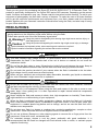
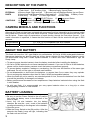
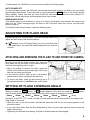
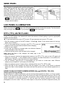
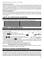
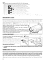
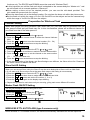
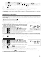
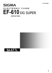
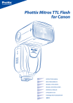
F18E10081
ELECTRONIC
FLASH
EF-610 DG SUPER
INSTRUCTIONS
EO-ETTL II
1
3
5
6
2
7
4
8
9
10
11
13
14
15
18
19
20
17
16
12
21
ENGLISH
The CE Mark is a Directive conformity mark of the European Community (EC).
DEUTSCH
Die CE-Kennzeichnung ist eine Konformitätserklärung des Herstellers, die dokumentiert, daß das betreffende
Produkt die Anforderungen von EG-Richtlinien einhält.
FRANÇAIS
Le label CE garantit la conformité aux normes établies par la Communauté Européenne.
NEDERLANDS
Het CE teken is een aanduiding voor de Europese Gemeenschap (EC).
ESPAÑOL
El logotipo CE es una directiva de conformidad con la Comunidad Europea (CE).
ITALIANO
Questo è il marchio di conformità alle direttive della comunità Europea (CE).
SVENSKA
CE-märket betyder att varan blivit godkänd av EU:s gemensamma kvalitetsnorm.
DANSK
CE-mærket er i overensstemmelse med de gældende regler i EU.
PORTUGUÊS
A marca CE garante a conformidade com as normas estabelecidas pela Comunidade Europeia.
SIGMA (Deutschland) GmbH
Carl-Zeiss-Str. 10/2, D-63322 Rödermark, F.R.GERMANY
Verkauf: 01805-90 90 85-0 Service: 01805-90 90 85-85 Fax: 01805-90 90 85-35
1
ENGLISH
Thank you very much for purchasing the Sigma EF-610 DG SUPER EO-TTL II Electronic Flash. This
product is specifically developed for the Canon EOS series SLR cameras. Depending on the camera
model, functions and operation may vary. Please read this instruction booklet carefully. To add to your
enjoyment of photography, the flash has a variety of features. To make the most of all these features
and to get the maximum performance and enjoyment from your flash, please read this instruction
booklet together with your camera’s instruction manual before using the flash, and also keep it handy
for your future reference.
PRECAUTIONS
In order to avoid causing any damage or injury, please read this instruction manual very carefully,
paying attention to the cautionary signs below, before using the flash.
Please take special note of the two cautionary signs below.
Using the product disregarding this warning sign might cause serious injury or
Warning !! other dangerous results.
Caution !!
Using the product disregarding this caution sign might cause injury or damage.
Symbol denotes the important points, where warning and caution are required.
Symbol contains information regarding the actions that must be avoided.
Warning !!
This flash contains high voltage circuits. To avoid electric shock or burns, do not attempt to
disassemble the flash. If the outside shell of the unit is broken or cracked, do not touch the
mechanism inside.
Do not fire the flash close to eyes. Otherwise the bright light could damage the eyes. Keep at
least 1m/3feet distance between face and the flash unit when taking a picture with flash.
Do not touch the synchro terminal of your camera when the flash is attached to the hot shoe.
High voltage circuitry could cause an electric shock.
Never use your camera in an environment where flammable, burnable, gas, liquids or chemicals,
etc, exist. Otherwise it might cause fire or explosion.
Caution !!
Do not use this flash unit on any camera other than the Canon EOS series cameras, otherwise
the flash may damage the circuitry of these cameras.
This flash unit is not waterproof. When using the flash and camera in the rain or snow or near
water, keep it from getting wet. It is often impractical to repair internal electrical components
damaged by water.
Never subject the flash and camera to shock, dust, high temperature or humidity. These factors
might cause fire or malfunctioning of your equipment.
When the flash is subjected to sudden temperature change, as when the flash unit is brought
from a cold exterior to warm interior, condensation might form inside. In such a case, place your
equipment in a sealed plastic bag before such a change, and do not use the flash unit until it
reaches room temperature.
Do not store your flash in a drawer or cupboard etc. containing naphthalene, camphor or other
insecticides. These chemicals will have a negative effects on the flash unit.
Do not use a thinner, Benzene or other cleaning agents to remove dirt or finger prints from the
component. Clean with a soft, moistened cloth.
For extended storage, choose a cool dry place, preferably with good ventilation. It is
recommended that the flash be charged and fired several times a month, to maintain proper
capacitor functioning.
2
DESCRIPTION OF THE PARTS
EXTERNAL
PARTS
1.Flash Head 2.AF Auxiliary Light 3.Bounce Angle; Up and Down
4.Bounce Angle; Right and Left 5.Bounce Lock and Release Button; Up and Down
6.Swivel Lock and Release Button; Right and Left 7.LCD Panel 8.Battery Cover
9.Shoe Ring
10.Shoe 11.Catch Light Panel
12.Wide Panel
CONTROLS
13.MODE Button 14.SEL SELECT Button 15. + Increment Button
16. - Decrement Button 17.ZOOM Button
18.TEST Button
19.LIGHT Button 20.Ready Light
21.Power Switch
CAMERA MODELS AND FUNCTIONS
Although this Flash unit has been equipped with numerous functions, depending on the camera model
being used some functions may have some limitations. Please confirm the type camera you have from
the list below. Please refer to explanations of each function through the instruction manual; If no
model information is specified, it means that this function of flash can be used with all type of EOS
cameras.
A type camera
B type camera
E-TTL(E-TTL II) Compatible EOS SLR cameras
All other EOS cameras except those listed above
ABOUT THE BATTERY
This flash unit uses four “AA” type Alkaline dry cell batteries, Ni-Cad or Ni-MH rechargeable batteries.
Manganese batteries can also be used but as they have a shorter life than Alkaline batteries, we do
not recommend using them. Please replace batteries if it takes more than 30seconds to light the
Ready Lamp.
◆ To assure proper electrical contact, clean the battery terminals before installing the batteries.
◆ Ni-Cad or Ni-MH batteries do not have standardized contacts. If you use Ni-Cad or Ni-MH batteries,
please confirm that the battery contacts touch the battery compartment properly.
◆ To prevent battery explosion, leakage or overheating, use four new AA batteries of the same type
and brand. Do not mix the type or new and used batteries.
◆ Do not disassemble or short-circuit the batteries, or expose them fire or water; they may explode.
Do not recharge the batteries other than Ni-Cad or Ni-MH rechargeable batteries.
◆ When the flash will not be used for an extended period of time, remove the batteries from the flash
to avoid the possibility of damage from leakage.
◆ Battery performance decreases at low temperatures. Keep batteries insulated when using the flash
in cold weather.
◆ As with any flash, it is recommended you carry spare batteries when on a long trip or when
photographing outdoors in cold weather.
BATTERY LOADING
1. Be sure to set the Power Switch to the off position
then slide the battery cover in the direction of the
arrow to open.
2. Insert four AA size batteries into the battery
chamber. Be sure the + and – ends of the batteries
are aligned according to the diagram in the chamber.
3. Close the cover.
4. Slide the Power Switch to the ON position. After few
seconds the Ready Lamp will light, indicating that
the flash unit can be fired.
3
5. Please press the “Test Button” to be sure that the flash is working properly.
AUTO POWER OFF
To conserve battery power, the flash unit automatically turns itself off when the flash is not used within
approximately 90 seconds. To turn the flash on again, depress the TEST button or the camera shutter
button halfway. Please note that the “Auto Power Off” mechanism does not work with wireless TTL
flash mode, normal slave flash, and designated slave flash modes.
ERROR INDICATION
If the battery power is not sufficient or there is an electric information error between the camera and
flash unit, the “Flash Coverage Angle” will blink on the LCD panel. When this occurs, turn the power
switch off and on.
If it still blinks after this procedure, check the battery power.
ADJUSTING THE FLASH HEAD
Depress the Bounce “Up and Down” Lock and Release Button and
adjust the flash head to the desired position.
◆ If
appears on the LCD panel when you turn on the flash, and
if this mark blinks, then the flash head is adjusted to an incorrect
position.
ATTACHING AND REMOVING THE FLASH TO AND FROM THE CAMERA
Be sure to turn off the Power Switch, then insert the
Shoe Base into the hot shoe on the camera and turn
the Shoe Locking Ring until it is tight.
◆ When you attach or remove the flash, grasp the
bottom of the flash to prevent damage to the shoe
foot and the camera’s hot shoe.
◆ If the camera’s built-in flash is set in up position,
please close it before you attach the flash unit.
◆ To remove the flash, rotate the shoe-locking ring in
the opposite direction of ◄LOCK mark, until it stops.
SETTING OF FLASH COVERAGE ANGLE
When you press the ZOOM button, the
symbol appears. Each time you press the ZOOM button,
the LCD panel display will change and indicate the zoom position in sequence as follows.
24mm → 28mm → 35mm → 50mm → 70mm → 85mm → 105mm → (Auto)
Generally, in the ETTL (TTL) mode, the flash will automatically set the zoom position according to the
focal length of your lens.
◆ When you turn on the main switch, the flash will memorize and set the zoom head position to the
last setting used.
◆ If you use a lens wider than the flash head setting, there may be under exposed areas around the
edge of the picture.
◆ Depending on the flash head setting, the flash’s Guide Number will be changed.
4
WIDE PANEL
This flashgun is equipped with a built-in wide panel,
which can provide an ultra wide 17mm angle of
coverage. Slide out the wide panel and catch light
panel and flip it down to cover the flash’s head. (Be
careful to slide the panels out smoothly.) Then put the
catch light panel back in its place. The coverage angle
setting of the flash will be set to 17mm automatically.
◆ If the built-in wide panel comes off accidentally, the
ZOOM button will not function. In this case please
contact the store where the flash was purchased or
a Sigma service station.
LCD PANEL ILLUMINATION
When you press the LIGHT button, the LCD panel will illuminate for about 8 seconds. The illumination
stays on longer than 8 seconds if you press the LIGHT button once again.
ETTL (TTL) AUTO FLASH
In the TTL AUTO Mode, the camera will control the amount of flash lighting to get the appropriate
exposure for the subject.
◆ “A” type cameras can be set in ETTL mode. “B” type cameras can be set in TTL mode.
1. Set the camera’s mode to Full-AUTO Mode. ( Usually □ Mode. If the camera does not have □
Mode, set to P Mode.)
2. Turn on the power switch of the flash, the ETTL (TTL) mark will
appear on the LCD panel and the flash will start charging.
3. Focus on your subject.
4. Check that the subject is located within the effective distance
range indicated on the LCD panel.
5. Press the shutter button, after the flash is fully charged.
Note: When the flash is fully charged, the ready light in the
viewfinder appears.
◆ When the camera receives the appropriate exposure, the ETTL (TTL) mark on the LCD panel will
appear for 5 seconds. If this indication does not appear, the flash illumination is not sufficent for
that situation. Please re-take the picture at a closer distance.
◆ The AF Auxiliary Light will turn on automatically as you focus on a dark area. Note: Effective
distance is up to about 0.7 to 9 meters (2.3-29.5 feet).
◆ When the camera is set to ‘Creative Zone’, the flash will be set to TTL / ETTL mode.
◆ When the flash is fully charged, the flash mark will appear in the finder. If the shutter is released
before the flash is fully charged, the camera will take the picture at a slow shutter speed with no
flash.
USING FLASH IN OTHER CAMERA MODES (Except EOS700, 750, 850)
Shutter Speed Priority Setting
By selecting the Tv mode of the camera, you can set the shutter speed from 30sec. to 1/X sync speed.
When you set the desired shutter speed, the camera will select the appropriate aperture value for the
scene. If the subject is too light or too dark, the aperture value indicator will blink and show the limit
values (maximum or minimum aperture). In such as case, the camera proceeds to take a flash
photograph at the limit value. Thus, the main subject in the picture should be exposed correctly, but
5
the background may become under or over exposed.
Aperture Priority Setting
By selecting the Av mode of your camera, the camera will select the appropriate shutter speed for the
scene. If the subject is too bright or too dark, the shutter speed indicator will blink and show the limit
(highest or slowest shutter speed) value. The highest shutter speed will be limited to the camera’s
normal flash synchronization speed. In such a case, the camera proceeds to take a flash photograph
at the limit value. Thus, the main subject in a picture should be exposed correctly, but the background
may become under or overexposed.
When used with M Mode
You can set the desired aperture value and shutter speed from 30 seconds to the camera’s flash sync
speed. If the camera’s exposure requires more light to achieve correct exposure for the inputted
values, the flashgun will provide sufficient light to give the correct exposure, within the working range
of the flashgun.
LIMITS OF CONTINUOUS SHOOTING
To prevent overheating of the flashgun’s circuitry, do not use your flash unit for at least 10 minutes
after continuously firing the flash for the number of exposures shown in the table below.
Mode
Number of Flash Exposures
TTL, M(1/1,1/2)
20 Continuous Flash Shots
M(1/4, 1/8)
25 Continuous Flash Shots
M(1/16-1/32)
40 Continuous Flash Shots
Multi
10 Cycle
MANUAL FLASH OPERATION
Manual flash is provided for shooting subjects when the correct exposure is difficult to obtain in the
TTL mode. In the manual flash mode, you can set the flash power level from 1/1 (full) to 1/128 power
in one step increments.
1. Set the camera’s exposure mode to M.
2. Press the MODE button on the flash unit to select M.
3. The flash power output value blinks when you press the SEL
button.
4. Press + or - button to set the desired flash power output.
5. The manual flash output display will stop blinking and remain
displayed after you press the SEL button again.
6. Adjust the focusing by pressing the shutter button, note the subject distance on the focus ring on the
lens. Then adjust the lens’ aperture value or flash power level until the distance indicated on the LCD
panel of the flashgun is equal to the subject distance.
7. When the Ready Light of the flash is illuminated, the unit is ready for use.
◆ You can calculate the correct exposure by using the following formula:
Guide Number “GN” / Flash to Subject Distance = F-stop
This flash unit will automatically calculate and indicate the appropriate subject distance according to
the above formula.(Please refer to table1 on the last page)
SECOND CURTAIN SYNCHRONIZATION
When you photograph a moving subject with slow synchronization, usually the furrow of the subject
will be exposed in front of the subject. The ordinary flash light will fire when the first shutter curtain is
fully opened, thus the subject will be exposed from the time flash is fired to the time the shutter is
closed (First curtain synchronization). When you use second curtain synchronization, the flash will fire
just before the second curtain begins to close and the subject will be exposed by ambient light from
the time the shutter opens until the flash fires. As a result the furrow of the subject will be recorded
6
behind the subject. This is a more natural effect.
◆ This mode cannot be used with EOS 700, 750, 850 cameras.
1. Set the desired picture-taking mode of the camera.
2. Press + or - button
mark will be displayed on the LCD
panel.
3. Adjust the focus and take the picture after confirming the ready
light.
◆ First curtain synchronization will be set if
mark is not displayed.
◆ If the camera is set to Full Auto Mode this function cannot be used.
◆ To cancel second curtain synchronization, turn off the
mark on the LCD panel by using + or buttons.
HIGH SPEED SYNC (FP) FLASH, A TYPE CAMERAS ONLY
When you take a picture with an ordinary flash, you cannot use a shutter speed faster than the
camera’s synchronized speed because the flash must fire when the shutter curtain is fully open. When
using the High Speed Sync mode, the flash keeps firing while the shutter curtain is running, thus you
can use a shutter speed faster than the shutter’s normal synchronization speed.
1. Select the camera’s exposure mode. (“Tv” or “M” modes can be used)
2. Select a shutter speed faster than the camera’s normal synchronization speed.
3. Slide the Power Switch of the flash to the ON position.
4. Choose the Flash Mode by using MODE button (“ETTL” or “M”
modes can be used).
mark is displayed on the
5. Press + or - button until the
LCD panel.
6. Focus on the subject
7. Check that the subject is located within the effective distance,
indicated on the LCD panel.
8. Confirm the
mark is in the viewfinder of the camera and then you can take the picture.
◆ With high-speed sync, the Guide Number changes depending on the shutter speed. The flash range
will be shorter (ie Guide Number will be smaller) when the shutter speed is faster. (Refer to table 2
on the last page).
◆ Selecting shutter speeds slower than the camera’s normal synchronization speed cancels Hi-speed
sync. Then the flash will automatically set to normal ETTL operation. To activate FP flash again,
follow the procedure above from point 1.
◆ It is possible to use the exposure compensation function with high speed synchronization operation.
To do so, please refer to your camera’s instruction manual regarding “exposure correction”.
◆
will disappear when Hi-speed sync (FP Flash) is cancelled.
FE LOCK
“FE” lock mode allows you to choose and lock the exposure before taking the picture.
1. Set the camera’s exposure mode (“P”, “Tv”, “Av”, “M” or “DEP”).
2. Set the flash’s mode to the E-TTL or the High Speed Sync.
3. Focus on the subject
4. Focus on the subject in the center AF frame of the viewfinder, and depress FE lock button.
◆ The flash unit will make a pre-flash, then calculate and memorize the amount of light necessary for
the correct exposure.
◆ The camera’s viewfinder will display “FEL” for 0.5 sec and the correct exposure will be set.
◆ If the viewfinder shows
mark, it means that power is not sufficient for correct exposure. Please
get closer to the subject and repeat from step 3.
7
5. After composing the picture, press the shutter button.
◆ This function may vary depending on camera model. For more details please refer to “FE lock”
instructions of your camera manual.
MODELING FLASH
If useing the Modeling flash, you can check the lighting and shadow effects before taking the picture.
(This function is limited to cameras which are compatible with modeling flash. For more details, please
refer to the instruction manual of your camera)
When the camera is set to modeling flash, the Flash panel will display the
symbol automatically.
EXPOSURE COMPENSATION
You can use flash exposure compensation in combination with normal exposure compensation to
control the background exposure level. Flash exposure compensation can be set to ±3 stops in 1/3
stop increments (or in 1/2 stop increments with some cameras).
◆ This mode cannot be used with EOS 620, 650, 700, 850 and 1000 cameras.
1. Press the SEL button and select
.
2. Press the + or - button to set the desired flash exposure
compensation amount.
3. Press the SEL button until the display stops blinking.
4. Focus on the subject.
5. Check that the subject is within the flash range as displayed on
the EF 610 DG Super’s LCD panel.
6. You can take the picture after confirming that the Ready Light of the flash is illuminated.
◆ To cancel exposure compensation, please start from step 1 and choose + 0 on display.
FB (Flash Exposure Bracketing)
With FB, you can get bracketed flash shots of the subject while the ambient exposure level remains
constant. The bracketed flash shots can be taken in the sequence of correct exposure, under
exposure and over exposure, up to ± 3 stops in 1/3EV increments
(or 1/2EV increments with some cameras).
1. Press the SEL button until
blinks.
2. Press the + or - button to set the flash exposure bracketing
amount.
3.
will be displayed after pressing the SEL button again.
4. Adjust the focusing.
5. Please check that the subject is within the flash range displayed on the EF- 610 DG Super’s LCD
panel.
6. Check the
mark is displayed in the virefinder and take the picture.
7. If it is necessary, repeat steps 4 to 6.
◆ This function will be cancelled automatically after making the third exposure.
MULTI FLASH MODE
While the shutter is open, the flash will fire repeatedly. By doing so a series of images of the subject
will be exposed in one frame. A bright subject with a dark background shows more effectively in this
mode. It is possible to set the firing frequency between 1Hz and
199Hz. Up to 100 flashes can be fired continuously. The maximum
number of flashes varies, depending on the flash’s power output
and firing frequency settings. (Please refer to table 3 on the last
8
page).
◆ This function cannot be used with EOS 700, 750, 850 cameras.
1. Set the camera’s exposure mode to M mode and set the F number.
2. Press the MODE button until the Multi-flash mode appears.
3. Press the SEL button until the flash firing frequency starts to blink.
4. Press the + or - button to set the desired flash frequency value.
5. After pressing the SEL button again, the flash power level will blink.
6. Press the + or - button to set the desired power level.
7. Press the SEL button again, the number of flashes will blink.
8. Press the + or - button to set the desired number of flashes.
9. Press the SEL button again, the display will stop blinking.
10. When the ready light of the flash is illuminated, the unit is ready to use.
Note: Please set the shutter speed longer than; Number of Flashes you want ÷ Firing Frequency
BOUNCE FLASH
When you take a photo with flash in a room, sometimes a strong shadow will appear behind the subject,
if you point the flash head upwards or sideways to reflect the light off the ceiling, wall etc. the subject
will be illuminated softly. Press the lock button and adjust the flash head to set the bounce angle.
UP: 0°, 60°, 75°, 90°
DOWN: 0°,7°
RIGHT: 0°, 60°, 75°, 90° LEFT: 0°, 60°, 75°,90°, 120°, 150°, 180°
When the bounce flash mode is activated, a bounce indicator
will appear on the LCD panel.
Choose a white surface for bouncing the flash, otherwise the
image’s colour may be incorrect.
Depending on the reflecting surface, the subject distance and other
factors, the effective distance range for the TTL AUTO may change.
Please check for correct exposure confirmation (ETTL or TTL mark
on the LCD panel) after releasing the shutter.
CLOSE-UP EXPOSURES
Bounce flash can be tilted 7° downward for close-ups. The Flash will be effective only for the subjects
will blink.
0.5 meter to 2 meters. When the flash head is tilted 7°,
CATCH LIGHT PANEL
This flash is equipped with a built-in catch
light panel, which can create a catch light in
the eyes of the subject when the bounce
flash mode is activated. Slide out the wide
panel and catch light panel, and then put
wide panel back in its place. (Be careful to
slide the panels out smoothly.)
◆
To create a catch light effectively, tilt the flash head upward 90 degrees and take pictures at a close
distance.
WIRELESS FLASH
When using the “Wireless Flash” mode, you can take pictures with a more three-dimensional feeling,
or make natural images by using shadowing depending on the flash position. This can be done without
any extension cord connecting the camera body and flash. In case of the EF-610 DG SUPER,
communication between the camera body and the flash will be achieved by the light produced by the
flash. In the “Wireless Flash” mode, the camera will calculate the correct exposure automatically.
◆The type A camera models can be used with “Wireless Manual Flash” and “Wireless Multi Flash”
9
functions only. The EOS750 and EOS850 cannot be used with “Wireless Flash”.
◆In this instruction we call the flash unit which is attached to the camera body the “Master unit ” and
we call a flash unit at a remote position a “Slave unit”.
◆When setting a slave unit at the desired position, you can use the mini-stand provided. This
mini-stand has a screw hole for a tripod.
◆Place the slave flash unit at the desired location. Do not place the slave unit within the picture area.
◆Set the flash unit within the range of 0.5m/1.5ft~5m/16ft from the subject and set the camera body
within the range of 1m/3ft~5m/16ft from the subject.
Preparation for Wireless Flash
Channel Setting
When other people are using Wireless Flash mode near you, your flash may be connected with the
other person’s flash and your flash may fire. In this circumstance, please set a different channel for
your flash from that of the other person’s.
Channel setting for Master unit
1. Press the MODE button to Select the
mark.
2. Press the SEL button several times to make the channel indicator
blink.
3. Press the + or - button to set the channel number. (C1~C4)
4. Press the SEL button several times to stop the blinking.
Channel setting for Slave unit
1. Press the MODE button to Select the ETTL/
/
mark.
2. Press the SEL button several times to make the channel indicator blink.
3. Press the + or - button to set the channel to the same number.
(C1 ~ C4) as the master unit.
4. Press the SEL button several times to stop the blinking.
◆ If the channel number of the Master and Slave flashguns are different, the Slave will not fire. Please set
the same number for Master and Slave.
Slave Unit ID Setting
When you use several Slave units, the Slave ID can be set to distinguish a Slave unit from Main flash.
◆ If you want to all Slave units to fire at the same flash output, this setting is not necessary.
1. Press the MODE button to Select the ETTL/
/
mark.
2. Press the SEL button three times to make the Slave ID indicator blink.
3. Press the + or - button and set the ID number. (1, 2 or 3)
4. Press the SEL button again so the display stops blinking.
◆ Repeat this process for each slave unit you are using, giving each one a different ID number.
Master Flash ON/OFF Setting
You can set the Master flash unit firing ON or OFF.
Master Flash unit firing ON
1. Press the MODE button to Select the
mark.
2. Press the + or - button to indicate the
mark.
Master Flash unit firing OFF
1. Press the MODE button to Select the
mark.
2. Press the + or - button to indicate the
mark.
WIRELESS ETTL AUTOFLASH (type A cameras only)
In this Wireless ETTL Autoflash function, the camera automatically calculates the correct exposure.
10
Wireless ETTL Autoflash with Flash Ratio OFF
If you require an equal power ratio for each flash unit, the slave ID setting is not necessary. You can set 1, 2
or 3 for each Slave Unit in use.
All the Slave flash units will fire at the same flash output and the ETTL autoflash system controls the total
flash amount automatically, to obtain a correct flash exposure.
The instructions below show how to reset the flashgun so no flash ratio is used and therefore equal power
is emmited from each flashgun.
◆ Please set the Master Flash unit as follows:
1. Press the MODE button to select the ETTL/
mark.
2. Press the + or - button to display the
mark (Master Flash will fire) or the shows
(Master Flash
will not fire) in the LCD display.
3. Press the SEL button several times and confirm that the flash ratio is 1:1.
◆ If the flash ratio is indicated as
or
, press the + or - button until 1:1 is displayed.
4. Place the Slave Unit at the desired position.
5. Make sure that the Master Unit and Slave Unit have both been charged.
◆ Master Unit’s Ready Light is lit and Slave Unit’s AF Auxiliary Light is blinking.
6. Focus on the subject and take the picture.
Slave ID, Wireless ETTL Autoflash With Flash Ratio (Two Slave Units)
The Wireless ETTL autoflash system, described as an example, consists of a master unit on the camera,
which will not fire, and two slave units. When you set the flash ratio, the ETTL autoflash system then
controls the total flash amount according to the flash ratio, to obtain a correct exposure.
◆ Only EOS-1V, EOS-3 cameras can use this function.
◆ The flash ratio can be set between 8 : 1 ~ 1 : 1 ~ 1 : 8.
◆ Please set the Slave ID to 1 and 2 for each Slave unit.
Set the Master unit as follow.
1. Please set the Master Flash unit firing mode to OFF (see Mater Flash ON / OFF setting).
mark.
2. Press the MODE button to Select the ETTL/
3. Press the SEL button several times to make the flash ratio indicator blink.
4. Press the + or - button and select . (Blinking)
5. Press the SEL button to make flash ratio value blink.
6. Press the + or - button to set the flash ratio.
7. Press the SEL button to make the Flash Ratio indicator stop blinking.
8. Place the Slave Unit at the desired position.
9. Confirm that both the master and slave units are charged.
10. Focus on the subject and take the picture.
◆ If you want to change the settings, you can start from step 3.
◆ If you want to cancel the setting, please set the flash ratio 1:1. (refer to step 4)
Slave ID, Wireless ETTL Autoflash With Flash Ratio (Three Slave Units)
The following wireless ETTL autoflash procedure is for a master unit with three (3) slave units. This procedure
sets the flash ratio for two Slave Units and the flash exposure compensation amount for other slave unit.
◆ Only EOS-1V and EOS-3 camera can use this function.
◆ Please set the Slave ID 1, 2 and 3 for each Slave unit (See Slave ID Setting).
Set the Master unit as follow.
1. Please set the Master Flash unit firing mode to OFF (See Master Flash ON / OFF Settings).
2. Press the MODE button to Select the ETTL/
mark.
3. Press the SEL button several times to make the flash ratio indicator display blink.
4. Press the + or - button to select the 1 2 3. (Blinking)
5. Press the SEL button to make the flash ratio value blink.
6. Press the + or - button to set the flash ratio.
7. Press the SEL button to make the flash exposure compensation display blink.
8. Press the + or - button and set the flash exposure compensation amount.
9. Press the SEL button to make the indicator stop blinking.
10. Place the Slave Units at the desired position.
11
11. Confirm that both the master and slave units are charged.
12. Focus on the subject and take the picture.
◆ If you want to change the settings or cancel the flash ratio settings, you can start from step 3.
Wireless High-Speed Sync (FP Flash)
1. Please set the master flash to Wireless Flash mode. (Refer to Page 21)
(Master Flash unit firing ON) or
/
(Master Flash
2. Press the + or - button to set to /
unit firing OFF).
3. The remainder of the procedure for setting wireless high-speed sync, is the same as for normal high-speed sync.
◆ It is not necessary to make any additional settings on the Slave units.
Wireless Flash Exposure Compensation
1. Please set master flash unit to the Wireless Flash Mode.
mark blink.
2. Press the SEL button to make
3. Press the + or - button to set the flash exposure compensation amount.
4. Press the SEL button several times to make exposure compensation indicator appear.
◆ It is not necessary to make any additional setting on the Slave units.
◆ You can also set the flash exposure compensation individually for each slave unit. (If using more than
one slave, you will need to apply steps 2-4 to each slave unit.)
Wireless FE Lock
1. First please set the flashgun to Wireless Flash mode.
2. Focus on the subject and press the FEL button on the camera.
3. The procedure for setting wireless EF lock is the same as for normal FE lock.
◆ It is not necessary to make any change to the settings on the Slave units.
Wireless Flash Exposure Bracketing (FB)
1. First set the flash to the Wireless Flash Mode.
mark blink.
2. On the Master Unit, press the SEL button several times to make the
3. Press the + or - button and set the flash exposure compensation amount.
4. Press the SEL button several times to make the indicator stop blinking.
5. The remainder of procedure for setting wireless FB is the same as for normal FB.
◆ It is not necessary to change any settings on the Slave units.
CHANGING THE WIRELESS MODE
Please set the flash as follows.
mark.
1. Press the MODE button to select the ETTL /
2. Press and hold the SEL button more than 2 seconds to make the mode indicator blink.
3. Press the MODE button and select the ETTL, M, or MULTI mode.
4. Press the SEL button to make the mode of indicator stop blinking.
WIRELESS MANUAL FLASH
You can manually set the slave unit’s flash output, with the master unit. The flash output among the slave
units can be uniform or varied. To determine the proper flash exposure, use a hand-held flash meter.
Wireless Manual Flash With Uniform Flash Output
Please set the Master flash unit as described below.
1. Please follow the procedure of Changing the Wireless Mode and set to the M/
mark.
2. Press the SEL button several times to make the flash output amount indicator blink.
3. Press the + button or – button to set the flash output amount.
4. Press the SEL button several times until the display stops blinking.
◆ If the master flash unit ON function is set, the master unit will also fire, at the same flash output.
Wireless Manual Flash With Varied Flash Output
12
You can set a different flash output for each slave unit(s) (the following explains the procedure for using
three slave flash units). Set the slave units to normal Wireless Flash mode.
Please set the master flash unit as follows.
1. Please follow the procedure for Changing the Wireless Mode and set to the M/
mark.
mark blink.
2. Press the SEL button several times to make the
3. Press the + or - button to select
indicator. (blinking)
4. Press the SEL button, making the flash output display and blink.
5. Press the + or - button to set the flash output amount for ID 1.
6. Press the SEL button make the flash output display and
blink.
7. Press the + or - button to set the flash output amount for ID 2.
8. Press the SEL button make the flash output display and
blink.
9. Press the + or - button to set the flash output amount for ID 3.
10. Press the SEL button to make the indicator stop blinking.
◆ If there are only two slave units, please select the
indicator at step 3 ( step 9 and step 10 should be
omitted).
WIRELESS MULTI FLASH
Set the master flash unit as follows.
1. Follow the procedure for Changing the Wireless Mode, and set to the MULTI/
2. Press the
3. Press the
4. Press the
5. Press the
6. Press the
7. Press the
8. Press the
mark.
SEL button to make the firing frequency display blink.
+ or - button to set the firing frequency.
SEL button to make the flash output amount display blink.
+ or - button to set the flash output amount.
SEL button to make the flash count display blink.
+ or - button to set the flash count.
SEL button to make the display stop blinking.
◆ The firing frequency and flash count will be the same for all slave units.
SLAVE FLASH
◆ When selecting this mode with the MODE button, make sure that the flash indicator mode (ETTL, M,
MULTI) is not displayed.
NORMAL SLAVE FLASH
Even if the EF-610 DG SUPER is not attached to the camera body, you can fire the flash by using another
flash unit.
◆ Built-in flash (E-TTL, E-TTL II) cannot be used.
◆ Please set your Master Flash unit to TTL autoflash (E-TTL, E-TTL II autoflash cannot be used) or Manual
flash mode.
1. Attach the flash unit to the camera’s hot shoe.
2. Set the camera’s exposure mode to the desired mode. If you use A or M mode, also set the desired aperture value.
3. Turn on the flash unit and press the shutter button half way.
◆ Now, the aperture value and film speed are automatically
transmitted to the flash unit.
4. Remove the flash unit from the camera.
5. Press the MODE button and select the
/
(Slave) mode.
6. Press the SEL button several times to make the flash output value
indicator blink.
7. Press the + or – button to set the flash output amount.
◆ Determine the appropriate flash output by setting the distance indicator on the LCD panel to coincide as
closely as possible with the actual distance from the slave flash to the subject. If the actual distance is
out of range, you will need to change the aperture value or film speed.
a. To change the aperture value: When the flash unit is set to the Slave mode, press the SEL button
until the aperture value blinks, then press the + or – button to set the desired aperture value. Then
13
press the SEL button to stop the display blinking.
b. To change the film speed: Press MODE to select the ISO, then press the SEL button to make the
indicator for the aperture value blink. Press the + or – button and set the desired film speed, then
press the SEL button once again. You will need to press the MODE button several times to return to
the slave mode.
8. Press the SEL button several times to make the display stop blinking.
9. Place the slave unit in the desired location. Do not place the slave unit within the picture area.
10. After confirming that all flash units are fully charged, press the shutter button to take the picture.
◆ When the EF-610 DG SUPER is fully charged, the AF Auxiliary Light will blink.
◆ The flash will not fire if the EF-610 DG SUPER is attached to the camera body while it is in the Slave
Mode setting.
DESIGNATED SLAVE FLASH
If using two or more EF-610 DG Super flash units, you can designate which flash will fire together by using
the channel settings. In this mode, one flash unit will be used as the Slave Controller and the others for
firing as Slaves.
Setting the Slave Flash unit(s) for firing
1. Attach the slave unit to the camera body.
2. Set the camera’s exposure mode to S or M.
3. Set the shutter speed to 1/30 or slower. (The slave controller unit (Master Flash) will transmit the
designated signal before the others fire. Thus if you use a shutter speed faster than 1/30, the firing flash
units will not be synchronized.)
4. Switch “ON” the flash unit and press the camera’s shutter button
halfway. (The aperture value and film speed are now automatically
transmitted to the slave flash unit.)
5. Remove the slave flash unit from the camera.
/
. (Slave Mode)
6. Press the MODE button and select the
7. Press the SEL button to make the channel display indicator blink.
8. Press the + or – button to set the channel number. (C1 or C2)
9. Press the SEL button to make the output amount display indicator of the flash blink.
10. Press the + or – button to set the flash output amount.
◆ Set the flash power by setting the distance indicator on the LCD panel to coincide as closely as possible
with the actual distance from the slave flash to the subject. If the actual distance is out of range, you
need to change the aperture value.
11. Press the SEL button several times to make the display stop blinking.
12. Place the slave unit in the desired location. Do not place the slave unit within the picture area.
Setting for Slave Controller unit
13. Attach the Slave Controller flash unit to the camera body.
14. Press the MODE button and select the
/
(Slave Mode).
15. Press the SEL button to make the channel display indicator blink.
16. Press the + or – button to set the same channel number as that set
on the firing flash unit.
17. Press the SEL button to make the flash output amount display
indicator blink.
18. Press the + button so the
mark is displayed and blinking.
19. Press the SEL button twice to make the display stop blinking.
20. After confirming that all flash units are fully charged, press the shutter button to take the picture.
◆ When the firing flash unit of EF-610 DG Super is fully charged, the AF Auxiliary Light will blink.
◆ As the slave control using is in
mode, the aperture on the slave control unit can not be changed.
◆ The Slave Controller unit functions only to control the slave unit.
14
SPECIFICATIONS
TYPE : Clip-on type serial-controlled TTL auto zoom electric flash
GUIDE NUMBER : 61 (ISO 100/m, 105mm head position)
POWER SOURCE : Four AA type alkaline batteries or Four AA type Ni-Cd batteries or,
: Four AA type Ni-MH Nickel-Metal Hydride batteries
RECYCLING TIME : about 7.0 sec. (Alkaline batteries)
: about 5.0 sec. (Ni-Cd, Ni-MH Nickel-Metal Hydride)
NUMBER OF FLASHES : about 120 flashes (Alkaline batteries)
: about 160 flashes (Ni-Cd, Ni-MH Nickel-Metal Hydride)
FLASH DURATION : about 1 / 700 sec. (full power firing)
FLASH ILLUMINATE ANGLE : 24~105mm motor powered control (17mm with Built-in Wide Panel)
AUTO POWER OFF : Available
WEIGHT : 330g / 11.6oz.
DIMENSIONS : 77mm (W) / 3.0in. x 139mm (H) / 5.5in. x 117mm (L) / 4.6in.
Disposal of Electric and Electronic Equipment in Private Households
ENGLISH
Disposal of used Electrical & Electronic Equipment (Applicable in the European Union and other European countries
with separate collection systems)
This symbol on the product, in the manual/warranty, and/or on the packaging indicates that this product must not be
treated as household waste. Instead it should be handed over to the appropriate collection point for the recycling of
electrical and electronic equipment. If your equipment contains easy removable batteries, please dispose of these
separately according to your local legislation. It is your responsibility to ensure that this product is recycled correctly. In doing so
you will help conserve natural resources, protect the environment and human health. For more detailed information about recycling
this product, please contact your local city office, your household waste disposal service or the shop where you purchased the product.
15
[Table1] GN (ISO100・m)
1/1
1/2
1/4
1/8
1/16
1/32
1/64
1/128
17mm
23.0
16.3
11.5
8.1
5.8
4.1
2.9
2.1
24mm
34.0
24.0
17.0
12.0
8.5
6.0
4.3
3.0
[Table 2] GN (ISO100・m)
1/125
1/160
1/180
1/250
1/320
1/350
1/400
1/500
1/640
1/750
1/800
1/1000
1/1250
1/1500
1/1600
1/2000
1/2500
1/3000
1/3200
1/4000
1/5000
1/6000
1/6400
1/8000
17mm
16.3
14.4
13.6
11.5
10.2
9.1
9.7
8.1
7.2
6.6
6.4
5.8
5.1
4.7
4.5
4.1
3.6
3.3
3.2
2.9
2.6
2.3
2.3
2.0
24mm
24.0
21.3
20.0
17.0
15.0
13.4
14.4
12.0
10.6
9.8
9.5
8.5
7.6
6.9
6.7
6.0
5.4
4.9
4.8
4.3
3.8
3.5
3.4
3.0
28mm
35.0
24.7
17.5
12.4
8.8
6.2
4.4
3.1
35mm
36.0
25.5
18.0
12.7
9.0
6.4
4.5
3.2
50mm
46.0
32.5
23.0
16.3
11.5
8.1
5.8
4.1
70mm
52.0
36.8
26.0
18.4
13.0
9.2
6.5
4.7
85mm
56.0
39.6
28.0
19.8
14.0
9.9
7.0
5.0
105mm
61.0
43.1
30.5
21.6
15.3
10.8
7.6
5.5
28mm
24.7
21.9
20.6
17.5
15.5
13.8
14.8
12.4
10.9
10.1
9.8
8.8
7.8
7.1
6.9
6.2
5.5
5.1
4.9
4.4
3.9
3.6
3.5
3.1
35mm
25.5
22.5
21.2
18.0
15.9
14.2
15.2
12.7
11.3
10.4
10.1
9.0
8.0
7.3
7.1
6.4
5.7
5.2
5.0
4.5
4.0
3.7
3.6
3.2
50mm
32.5
28.8
27.1
23.0
20.3
18.2
19.4
16.3
14.4
13.3
12.9
11.5
10.3
9.4
9.1
8.1
7.3
6.6
6.4
5.8
5.1
4.7
4.5
4.1
70mm
36.8
32.5
30.6
26.0
23.0
20.6
22.0
18.4
16.3
15.0
14.5
13.0
11.6
10.6
10.3
9.2
8.2
7.5
7.3
6.5
5.8
5.3
5.1
4.6
85mm
39.6
35.0
33.0
28.0
24.7
22.1
23.7
19.8
17.5
16.2
15.7
14.0
12.5
11.4
11.1
9.9
8.9
8.1
7.8
7.0
6.3
5.7
5.5
4.9
105mm
43.1
38.1
35.9
30.5
27.0
24.1
25.8
21.6
19.1
17.6
17.1
15.3
13.6
12.5
12.1
10.8
9.6
8.8
8.5
7.6
6.8
6.2
6.0
5.4
[Table 3] MULTI FLASH MODE
1/128
1/64
1~5Hz
1~100
1~3 Hz
1~60
1 Hz
1~14
6~7 Hz
1~90
4~5 Hz
1~50
2 Hz
1~7
8~9 Hz
1~80
6 Hz
1~30
3 Hz
1~6
10~11 Hz
1~70
7~9 Hz
1~20
4~7 Hz
1~5
12~14 Hz
1~60
10~19 Hz
1~15
8~9 Hz
1~4
15~19 Hz
1~50
20~199 Hz
1~12
10~199 Hz
1~3
20~199 Hz
1~40
1 Hz
1~30
1 Hz
1~4
1~3 Hz
1~90
2 Hz
1~20
2 Hz
1~3
4~5 Hz
1~80
3 Hz
1~10
3~119 Hz
1~2
6~7 Hz
1~70
4~199 Hz
1~6
8~9 Hz
1~50
10 Hz
1~45
11~14 Hz
1~35
15~19 Hz
1~30
20~50 Hz
1~25
60~199 Hz
1~20
1/32
1/16
1/8
1/4
16