1
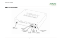
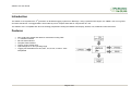
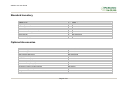
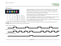
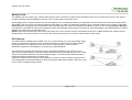
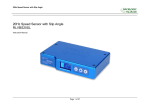
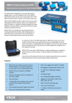
VBOX II Lite User Guide
VBOX II Lite 5Hz GPS Data Logger
User Guide
Page 1 of 21
VBOX II Lite User Guide
VBOX II LITE OVERVIEW .................................................................................................................................................................. 4
INTRODUCTION................................................................................................................................................................................. 5
FEATURES ......................................................................................................................................................................................... 5
STANDARD INVENTORY .................................................................................................................................................................. 6
OPTIONAL ACCESSORIES............................................................................................................................................................... 6
OPERATION ....................................................................................................................................................................................... 7
GETTING STARTED ........................................................................................................................................................................ 12
VBOX II LITE ‘.VBO’ FILE FORMAT................................................................................................................................................ 14
VBOX.EXE SOFTWARE .................................................................................................................................................................. 15
FIRMWARE UPGRADES ................................................................................................................................................................. 16
SPECIFICATION............................................................................................................................................................................... 17
CONNECTION DATA ....................................................................................................................................................................... 18
CAN BUS DATA FORMAT............................................................................................................................................................... 20
CONTACT INFORMATION .............................................................................................................................................................. 21
Page 2 of 21
VBOX II Lite User Guide
EC Declaration of Conformity
We declare that this product has been tested to and meet the requirements of:
EC Directive 2004/104/EC
“Adapting to Technical Progress Council directive 72/245/EEC relating to the radio interference (Electromagnetic Compatibility) of vehicles and
amending directive 70/156/EEC on the approximation of the laws of the member states relating to the type-approval of motor vehicles and their
trailers.”
And has also been assessed, via Technical Construction File, by an independent DTI Competent Body and found to be in conformance with the
essential requirements of:
EC Directive 89/336/EEC (and amending directives)
“Council Directive of 03 May 1989 on the approximation of the laws of the member states relating to electromagnetic compatibility.”
DTI Competent Body responsible for issuing certificate of compliance:
3C Test Ltd,
Silverstone Technology Park,
Silverstone,
Northants
NN12 8GX
Page 3 of 21
VBOX II Lite User Guide
VBOX II Lite Overview
Page 4 of 21
VBOX II Lite User Guide
Introduction
nd
The VBOX II Lite represents the 2 generation of GPS data logging system from Racelogic. Using a powerful GPS engine, the VBOX II Lite can log GPS
and other data at 5Hz. The logged data is stored directly onto a compact flash card for easy transfer to a PC.
The VBOX II Lite is compatible with all of the existing peripherals including the Multifunction display, ADC03, TC8, FIM03 and Yaw rate sensor.
Features
•
•
•
•
•
•
•
Non-contact 5Hz speed and distance measurement using GPS
1 x CAN Bus interface
RS-232 serial interface
Compact Flash Interface
Trigger / Event marker input
Input Voltage 6V to 18V operating range
Logging rate selectable from 5Hz, 2Hz, 1Hz, 0.5Hz, or 20Hz / 10Hz
interpolated
Page 5 of 21
VBOX II Lite User Guide
Standard Inventory
Description
VBOX II Lite
Cigar Lighter adaptor
GPS Magnetic Aerial
32Mb Compact Flash Card
PCMCIA Compact Flash Adaptor
CD ROM containing VBOX software
Serial PC Cable
User Manual
Padded Carrying Case
Qty
1
1
1
1
1
1
1
1
1
Racelogic Part #
VB2L
RLVBCAB10
RLVBACS015
RLVBACS005
RLVBACS028
RLVBACS030
RLVBCAB01
RLVBACS031
RLVBACS016
Optional Accessories
Description
4.5Ah battery pack
Mains Charger
Brake Pedal Trigger
Hand-held brake trigger
Logging Start/Stop Switch
Multifunction Display
8 Channel (16bit) Analogue Interface
8 Channel (10bit) Analogue Interface
4 Channel Frequency Input Module
8 Channel Vehicle CAN Interface
8 Channel Thermocouple Interface
Can to Analogue Output Module
Single Yaw Rate Sensor + 2 axis G Sensor
Inertial Measurement Unit. 3 Yaw Rate Sensors & 3 accelerometers
Page 6 of 21
Racelogic Part #
RLVBACS012
RLVBACS020
RLVBACS004
RLVBACS009
RLVBACS010
RLVBDSP03
RLVBADC03
RLVBADC02
RLVBFIM03
RLVBCAN01
RLVBTC8
RLVBDAC01
RLVBYAW02
RLVBIMU01
VBOX II Lite User Guide
Operation
Power
The VBOX Lite can be powered from a wide range of voltage sources including the supplied Vehicle Cigar adapter, or other source provided by the user. The
maximum operating voltage input must not exceed 18V DC. Failure to observe this could result in damage to the VBOX.
As an optional extra a battery pack is available from Racelogic RLVBACS012.
The battery pack is a 6v 3.8amp hour Nickel Metal Hydride unit, with a built in charging and monitoring circuit.
The battery is plugged into the two pin power socket on the front of the VBOX to provide power for up to 6
hours (4 hours with the display attached).
The battery pack can be charged via two methods, either by plugging the VBOX cigar lighter adapter into the
pack, or by using the mains charger. The battery pack can be either discharged fully and then re-charged, or
partially discharged and then re-charged, there is no memory effect on NiMh batteries.
To protect the battery cells from damage, the battery will only charge when the temperature range is between 0
& 46°C. If whilst charging the internal temperature of the battery reaches 46°C, the charge will be turned off
until the internal temperature reduces to 43°C and the charge status led (25% 50% , 75% or 100% ) will flash.
The charge will then automatically restart.
Whilst charging, the 25%, 50%, 75% and 100% will illuminate in succession to give an indication of the total charge time. When the battery is fully charged,
the 100% led will remain illuminated, and the charging led will turn off. Occasionally the battery will turn the charging back on to keep the battery at full
capacity. To check the state of the battery charge; press and hold in the white button on the side of the box. There are four LED's which will light up indicating
how much charge is left in the battery. 100% LED indicating 100% charge, 75% led indicating up to 99% charge, 50% led indicating up to 74% and 25% led
indicating up to 49% charge. When the battery is at a level not suitable for powering the VBOX, the 25% led will flash.
The battery can be connected to a charger, and also the VBOX at the same time. This allows the battery to be charged whilst the external source is powering
the VBOX. In such a situation, you can power the VBOX from the cigar lighter, with the battery acting as a back up if the ignition is turned off which
sometimes stops the power to the cigar lighter.
When the battery is close to fully discharged, the VBOX will give an audible warning by a slow series of beeps from the internal buzzer. You should have
around 5 minutes of time left when these beeps begin.
Page 7 of 21
VBOX II Lite User Guide
LED Indicators
The green LED (ST) is used to indicate the number of satellites currently in lock. If the yellow
LED (SC) is flashing whilst the green (ST) LED is off, then the VBOX has no satellite lock.
If this is the case then check that you have the GPS antenna connector correctly fitted to the
VBOX. Also check that the antenna has a clear view of the sky.
The VBOX will normally lock onto satellites within 30 seconds of power up. However on its first
use it can take up to 20 minutes to acquire satellite lock.
The yellow LED (SC) flashes to indicate start of count. When satellite lock occurs the number of
green LED flashes between yellow flashes indicates the number of satellites in lock.
When a Compact Flash memory device is inserted into VBOX II Lite the blue LED (CF) will flash
to indicate that the VBOX is writing to the device.
The amber LED is used to indicate either CAN activity (CN) or if the unit is a DGPS version (DG), then this LED will come on when DGPS lock has been
successful.
The following diagram shows an example of SAT LED pulse sequence.
Sequence showing 1 Satellite
1
1
1
1
Sequence showing 4 Satellites
Delay
1
2
3
4
Delay
1
2
Sequence showing 0 Satellites
Delay (Approximately 1 second )
Delay (Approximately 1 second )
Page 8 of 21
3
4
VBOX II Lite User Guide
Memory Cards
The VBOX II Lite can accept Type-I compact flash memory cards. The memory cards must be formatted using FAT or FAT16 but not FAT32. This option is
normally selectable when formatting the memory card in a card reader connected to a PC.
When logging data to compact flash the blue CF LED will flash or be constantly illuminated. It is important not to remove the flash card while the blue LED is
illuminated. If the card is removed while the VBOX is writing data to it, there is a risk that the data file may be corrupted resulting in loss of data. If ‘Log only
when moving’ is the logging mode selected then wait a short time after the vehicle has stopped for the Blue CF LED to go out. If ‘Log only when moving’ is
not selected i.e. the VBOX is continuously logging then press the Start/stop logging switch if connected or enter VBOX setup in the VBOX software to stop the
VBOX logging data to the compact flash card.
NOTE If you cannot do either of the above then just remove the card. If however the file is reported as corrupt by the VBOX software then load the file into
Notepad and go to the end of the file. It is usual in this case that the last entry is corrupt, so delete it and re-save the file.
GPS Antenna
The GPS Antenna supplied with the VBOX II Lite is a 5v active antenna. For the best possible signal
quality, it is important to maintain a clean connection between the antenna and the VBOX. Before
fixing the antenna to the VBOX, ensure that there are no dust particles in either connector.
Replacement antennas are available by contacting your VBOX distributor.
The antenna is a magnetic mounting type for quick and simple mounting to the vehicle roof. For
optimum GPS signal reception, make sure that the antenna is fitted to the highest point of the vehicle
away from any obstructions that may block satellite reception. The GPS antenna works best with a
metal ground plane underneath (eg. Vehicle roof).
Please also note that when using any GPS equipment, a clear sky view is important. Objects in the
surrounding area such and tall buildings or trees can block the GPS signal causing a reduction or loss
in the number of satellites being tracked.
Page 9 of 21
VBOX II Lite User Guide
Digital Inputs
The DIGITAL INPUT (Socket 4) contains the two digital inputs for the VBOX II Lite. Digital input 1 is also referred to as the trigger / event marker input.
A hand-held trigger is available to allow the user to record marker events in the VBOX II Lite data file.
A remote logging on/off switch is also available.
If you wish to use both digital inputs at the same time, you will require a 3way digital splitter (RLVBACS027).
Page 10 of 21
VBOX II Lite User Guide
CAN / RS232 Ports
The VBOX II Lite is equipped with a CAN Bus interface and a RS232 serial port. The RS232 port is used for all communication between the VBOX and laptop
PC. The RS232 port is in Socket 5 on the VBOX II Lite. The RS232 port is able to transmit live data from the VBOX to the PC for viewing and performing realtime tests.
The CAN Bus port is in Socket 2 of the VBOX II Lite. The function of this port is configurable by the user for use by either Racelogic modules (Internal mode)
or the users own CAN Bus equipment (External mode). See the section ‘Setup’ in the VBOX software manual.
The CAN Bus port also contains a secondary RS232 port for direct connections to the GPS engine for Local DGPS correction connection.
Page 11 of 21
VBOX II Lite User Guide
Getting Started
Required equipment (All supplied as standard unless specified)
VBOX II Lite
Fully charged battery pack or Cigar lighter 12v adapter lead
GPS Antenna
Blank Compact Flash Card
RS232 Cable
VBOX Software CD
Laptop PC(not supplied)
1.Install Software
2.Place VBOX in vehicle
3.Fit antenna connector to VBOX
4. Mount GPS antenna on vehicle roof
5.Connect serial cable (CAB01) to laptop
6. Connect other end of serial cable to VBOX
Page 12 of 21
VBOX II Lite User Guide
7. Connect the power cable/ battery pack to the
VBOX
8. If using 12v power cable, connect to vehicle
9. With the power applied, the red PWR led should illuminate. The VBOX II Lite will start
searching for satellites. The ST led will indicate the number of satellites currently in lock.
For best results ensure the VBOX has acquired a lock on 5 or more satellites, essential for
quality signal reception. When using the VBOX for the first time or when using the VBOX
after a long period of time, allow the VBOX to sit for between 5 and 10 minutes to recollect data needed to track satellites.
As the vehicle begins moving, the blue CF led should begin to flash as data is recorded to
compact flash, if inserted. When the vehicle comes to a stop, the blue CF led should
extinguish. The card can now be removed and the data transferred onto the PC for
analysis. If no compact flash card is fitted then data will be recorded to the internal RAM.
NOTE before using the Internal RAM, the RAM should be cleared. See section ‘Setup’ of
the VBOX Software manual.
Page 13 of 21
VBOX II Lite User Guide
VBOX II Lite ‘.VBO’ File Format
The VBOX II Lite data files are saved in standard space de-limited text
format. This allows the data to easily be imported into third party applications
such as word processors or spreadsheets. The files each contain a header
section before the main data that describes the channel content and
information about the VBOXII such as serial number and firmware version.
The [Column names] parameter specifies the data in each column of the data
section.
An example of a VBOX VBO file is shown on the right.
File created on 15/04/2004 @ 08:21
[header]
satellites
time
latitude
longitude
velocity knots
heading
height
Vertical velocity m/s
[channel units]
[comments]
(c)2003 Racelogic
VBoxII Version4.2d
Serial Number: 004866
Log Rate (Hz) : 20.00
Software Version :-8.1.4 (build45)
[column names]
sats time lat long velocity heading height vert-vel
[data]
004 072148.26 +3119.408424 +00062.635139 015.13 356.06 +00155.27 -00000.22
004 072148.27 +3119.408592 +00062.635104 015.17 356.02 +00147.93 -00000.37
004 072148.28 +3119.408629 +00062.635108 015.09 355.92 +00147.92 -00000.40
004 072148.29 +3119.408669 +00062.635115 014.98 355.64 +00147.92 -00000.35
004 072148.30 +3119.408711 +00062.635119 015.00 355.87 +00147.91 -00000.47
004 072148.31 +3119.408753 +00062.635122 015.03 356.11 +00147.90 -00000.61
004 072148.32 +3119.408797 +00062.635125 015.16 356.48 +00147.88 -00000.84
004 072148.33 +3119.408837 +00062.635130 015.06 356.32 +00147.88 -00000.67
004 072148.34 +3119.408874 +00062.635138 014.84 355.81 +00147.91 -00000.14
004 072148.35 +3119.408919 +00062.635144 015.03 355.84 +00147.90 -00000.28
004 072148.36 +3119.408968 +00062.635147 015.42 356.17 +00147.87 -00000.66
004 072148.37 +3119.409013 +00062.635148 015.56 356.72 +00147.87 -00000.69
Page 14 of 21
VBOX II Lite User Guide
VBOX.EXE Software
The VBOX.EXE software is used for configuration of the VBOX II
Lite and also for analysis of the VBO data files.
For further information on the VBOX.EXE software refer to the
VBOX Software manual supplied with VBOX II Lite.
Page 15 of 21
VBOX II Lite User Guide
Firmware Upgrades
Firmware refers to the operating software inside the VBOX II Lite. The firmware is responsible for all of the functions within the VBOX and from time to time,
firmware updates will be released by Racelogic to improve or enhance the way that the VBOX works. The latest firmware will always be available on the
Racelogic web site in the downloads directory:http://www.racelogic.co.uk/2003/vbox/downloads.htm
It is recommended to check the web site periodically for updates. The VBOX II Lite upgrade files have a “.ruf” file extension. To upgrade the VBOX II Lite
firmware, download the latest firmware file from the Racelogic web site and copy this file onto your PC. If you have done a full VBOX CD installation then you
will have the upgrade programme automatically installed in the Utilities folder of VBOX folder. If not then this can also downloaded from the website.
Connect you pc to the VBOX via the VBOX serial lead and apply power to the VBOX.
Either ‘double click’ on the .ruf upgrade file, which auto runs the upgrader software, or run the upgrader software and load in the .ruf firmware upgrade file.
Then follow the onscreen instructions and the VBOX firmware will be upgraded. At the end of the process power down the VBOX when prompted, before
further use
During the upgrade process an upgrade log file will have been created. This log file can be emailed to the support address below should any problems arise.
If you have any questions regarding upgrade of VBOX, please do not hesitate to contact [email protected]
Page 16 of 21
VBOX II Lite User Guide
Specification
GPS
Velocity
Accuracy
Distance
Accuracy
0.05% (<50cm per Km)
Units
Update rate
Resolution
Height accuracy
Metres / Feet
5 Hz
1cm
10 Metres 95% CEP**
Time
Resolution
Accuracy
0.01 s
0.05 s
Units
Update rate
Maximum velocity
Minimum velocity
Resolution
0.2 Km/h (averaged over 4
samples)
Km/h or Mph
5 Hz
1000 Mph
0.1 Km/h
0.01 Km/h
Absolute Positioning
Accuracy
Accuracy with DGPS
Update rate
Resolution
3m 95% CEP**
< 1.8m 95% CEP**
5 Hz
1 cm
Heading
Resolution
Accuracy
0.01°
0.2°
Power
Input Voltage range
Current
6v-18v DC
Typically 560mA
Acceleration
Accuracy
Maximum
Resolution
Update rate
1%
20 G
0.01 G
5 Hz
Environmental and Physical
Weight
Size
Operating temperature
Storage temperature
Approx 0.5Kg
119mm x 128mm x 30mm
-30°C to +60°C
-40°C to +80°C
Memory
Compact Flash
Recording time
Type I
Dependent on flash card
capacity*
* Approximately 4.3Mb per hour used when logging GPS
data at 20Hz
Definitions
** CEP = Circle of Error Probable
95% CEP (Circle Error Probable) means 95% of the time the position readings will fall
within a circle of the stated diameter
Inputs
CAN Bus
Racelogic modules
Up to 32 channels from any combination of ADC02, ADC03, FIM03, TC8, Yaw sensor or CAN01
Digital
Trigger/Event
On/Off Logging control
Digital input can be used as test start, end and line conditions or to externally mark events in the logged data.
Remote log control from hand-held switch
Page 17 of 21
VBOX II Lite User Guide
Connection Data
3 pin LEMO socket
2 pin LEMO socket
Connector
PIN
1
2
Chassis
1 POWER
In/Out
Description
I
Power +
I
Ground
Ground
Type
Lemo 2 pin
Range
6V to 18V
0V
Page 18 of 21
5 pin LEMO socket
VBOX II Lite User Guide
Connector
PIN
1
2
3
4
5
Chassis
2 CAN BUS
Type
Lemo 5 pin
In/Out
Description
O
RS232 Tx (PORT B Local DGPS)
I
RS232 Rx (PORT B Local DGPS)
I/O
CAN Bus
I/O
CAN Bus
O
+V Power
Ground
Connector
PIN
1
2
3
4
5
Chassis
3 RS232
In/Out
O
I
O
Connector
PIN
1
2
3
Chassis
4 DIGITAL INPUT
Type
Lemo 3 pin
In/Out
Description
O
Ground
I
Digital Input 2. Start/Stop Logging
I
Digital Input 1. Brake Trigger
Ground
Type
Range
±12v
±12v
Lemo 5 pin
Description
RS232 Tx Serial Data Transmit
RS232 Rx Serial Data Receive
+V Power
Ground
Range
±12v
±12v
Range
0V to 5V
0V to 5V
Antenna connector
Connector
PIN
Center
Chassis
ANT
In/Out
-
Type
SMA
Description
RF Signal / Power for active antenna
Ground
Range
Page 19 of 21
VBOX II Lite User Guide
CAN Bus data format
Format
ID**
Motorola
Data Bytes
1
2
3
4
5
6
7
8
0x301
(1) Sats in
(2) Time since midnight UTC
(3) Position – Latitude DDMM.MMMMM
view
0x302
50ms
(4) Position – Longitude DDMMM.MMMMM
(5) Velocity. (Knots)
(6) Heading. (Degrees)
0x303
50ms
(7) Altitude. WGS 84. (Metres)
(8) Vertical velocity. (M/S)
Unused
(9) Status
(10) Status
0x304
50ms
Unused
(11) Longitudinal Accel. (G)
(12) Lateral Accel. (G)
0x305
50ms
(13) Distance. (Meters)
**Default Identifiers. The identifier values can be changed using the configuration software.
Update
rate
50ms
(1) If Satellites in view < 3 then only Identifier 0x301 transmitted and bytes 2 to 8 are set to 0x00.
(2) Time since midnight. This is a count of 10mS intervals since midnight UTC. (5383690 = 53836.90 seconds since midnight or 14 hours, 57
minutes and 16.90 seconds)
(3) Position, Latitude * 100,000 (515924579 = 51 Degrees, 59.24579 Minutes North). Latitude highest bit indicates north/south hemisphere.
0=north, 1=south, Bit 7 in Status is also set.
(4) Position, Longitude * 100,000 (5882246 = 0 Degrees, 58.82246 Minutes West). Longitude highest bit indicates east/west of Greenwich
meridian. 0=west,1=east. Bit 6 in Status is also set.
(5) Velocity, 0.01 knots per bit.
(6) Heading, 0.01° per bit.
(7) Altitude, 0.01 meters per bit, signed.
(8) Vertical Velocity, 0.01 m/s per bit, signed.
(9) Status. 8 bit unsigned char. Bit 0=VBOX Lite, Bit 1=Open or Closed CAN Bus (1=open), 2=VBOX3
(10)Status is an 8 bit unsigned char. Bit 0 is always set, Bit 3=brake test started, Bit 4 = Brake trigger active, Bit 5 = DGPS active
(11) Longitudinal Acceleration, 0.01G per bit, signed.
(11)Lateral Acceleration, 0.01G per bit, signed.
(13) Distance, 0.000078125 meters per bit, unsigned.
The VBOX CAN database is available in Vector Database (DBC File) format on request from Racelogic
Page 20 of 21
VBOX II Lite User Guide
Contact Information
Racelogic Ltd
Unit 10 Swan Business Centre
Osier Way
Buckingham
MK18 1TB
UK
Tel: +44 (0) 1280 823803
Fax: +44 (0) 1280 823595
Email: [email protected]
Web: www.racelogic.co.uk
Revision
1
2
3
4
5
6
Date
21/10/2005
18/09/2006
05/06/2007
07/11/2007
03/12/2007
30/04/2008
Description
First Draft
Addition of text describing Digital inputs
Inclusion of Declaration of Conformity Statement
Correction to CAN format table
Addition of Format: Motorola to CAN Bus Data Format table
Updated Racelogic contact information
Page 21 of 21
Author
JDH
KB
CAS
KB
NT
JH