1
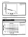
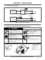
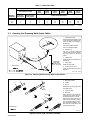
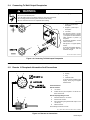
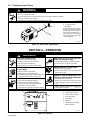
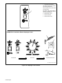
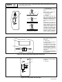
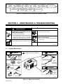
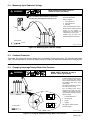
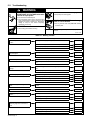
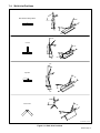
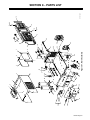
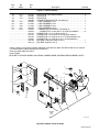
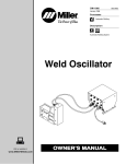
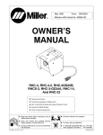
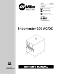
March 1993 Form: OM-207 Effective With Serial No. KD400224 OWNER’S MANUAL Maxstar 91 CC/DC Welding Power Source For GTAW Welding 90 Amperes, 14 Volts DC At 20% Duty Cycle Uses Single-Phase Input Power Thermostat Protection Against Overheating Touch Start For GTAW Welding 14-Pin Remote Control Receptacle Read and follow these instructions and all safety blocks carefully. cover 8/92 − ST-157 356 Give this manual to the operator. Have only trained and qualified persons install, operate, or service this unit. For help, call your distributor Call your distributor if you do not understand the directions. or: MILLER ELECTRIC Mfg. Co., P.O. Box 1079, Appleton, WI 54912 414-734-9821 PRINTED IN USA 1 TABLE OF CONTENTS SECTION 1 − SAFETY INFORMATION . . . . . . . . . . . . . . . . . . . . . . . . . . . . . . . . . . . . . . . . . . . . . . . . . . . . 1 SECTION 2 − SPECIFICATIONS 2-1. 2-2. Volt-Ampere Curves . . . . . . . . . . . . . . . . . . . . . . . . . . . . . . . . . . . . . . . . . . . . . . . . . . . . . . . . . . . . Duty Cycle . . . . . . . . . . . . . . . . . . . . . . . . . . . . . . . . . . . . . . . . . . . . . . . . . . . . . . . . . . . . . . . . . . . . 2 2 SECTION 3 − INSTALLATION 3-1. 3-2. 3-3. 3-4. 3-5. 3-6. Typical Process Connections . . . . . . . . . . . . . . . . . . . . . . . . . . . . . . . . . . . . . . . . . . . . . . . . . . . . Selecting A Location And Moving Welding Power Source . . . . . . . . . . . . . . . . . . . . . . . . . . . . Selecting And Preparing Weld Output Cables . . . . . . . . . . . . . . . . . . . . . . . . . . . . . . . . . . . . . . Connecting To Weld Output Receptacles . . . . . . . . . . . . . . . . . . . . . . . . . . . . . . . . . . . . . . . . . . Remote 14 Receptacle Information And Connections . . . . . . . . . . . . . . . . . . . . . . . . . . . . . . . Connecting Input Power . . . . . . . . . . . . . . . . . . . . . . . . . . . . . . . . . . . . . . . . . . . . . . . . . . . . . . . . 3 3 4 5 5 6 SECTION 4 − OPERATION . . . . . . . . . . . . . . . . . . . . . . . . . . . . . . . . . . . . . . . . . . . . . . . . . . . . . . . . . . . . . . . 6 SECTION 5-1. 5-2. 5-3. 5-4. 5-5. 5 − MAINTENANCE & TROUBLESHOOTING Routine Maintenance . . . . . . . . . . . . . . . . . . . . . . . . . . . . . . . . . . . . . . . . . . . . . . . . . . . . . . . . . . . Measuring Input Capacitor Voltage . . . . . . . . . . . . . . . . . . . . . . . . . . . . . . . . . . . . . . . . . . . . . . . Overload Protection . . . . . . . . . . . . . . . . . . . . . . . . . . . . . . . . . . . . . . . . . . . . . . . . . . . . . . . . . . . . Changing Amperage/Voltage Meter Hold Function . . . . . . . . . . . . . . . . . . . . . . . . . . . . . . . . . . Troubleshooting . . . . . . . . . . . . . . . . . . . . . . . . . . . . . . . . . . . . . . . . . . . . . . . . . . . . . . . . . . . . . . . 10 11 11 11 12 SECTION 6 − ELECTRICAL DIAGRAMS . . . . . . . . . . . . . . . . . . . . . . . . . . . . . . . . . . . . . . . . . . . . . . . . . . . 13 SECTION 7 − TUNGSTEN ELECTRODE 7-1. 7-2. Selecting Tungsten Electrode . . . . . . . . . . . . . . . . . . . . . . . . . . . . . . . . . . . . . . . . . . . . . . . . . . . . Preparing Tungsten . . . . . . . . . . . . . . . . . . . . . . . . . . . . . . . . . . . . . . . . . . . . . . . . . . . . . . . . . . . . 16 17 SECTION 8 − PARTS LIST Figure 8-1. Main Assembly . . . . . . . . . . . . . . . . . . . . . . . . . . . . . . . . . . . . . . . . . . . . . . . . . . . . . . . . . . . . Figure 8-2. Module, Power & Diode . . . . . . . . . . . . . . . . . . . . . . . . . . . . . . . . . . . . . . . . . . . . . . . . . . . . . 18 20 OM-207 − 3/93 1 SECTION 1 − SAFETY INFORMATION mod1.1 2/93 Read all safety messages throughout this manual. Obey all safety messages to avoid injury. Learn the meaning of WARNING and CAUTION. 1 2 2 WARNING • Do not touch live electrical parts. • Disconnect input power before MOVING PARTS can injure. • Keep away from moving parts. • Keep all panels and covers closed 4 installing or servicing. when operating. 5 READ SAFETY BLOCKS at start of Section 3-1 before proceeding. WARNING 6 Safety Alert Symbol 2 Signal Word WARNING means possible death or serious injury can happen. CAUTION 3 ELECTRIC SHOCK can kill. 1 CAUTION means possible minor injury or equipment damage can happen. 3 Statement Of Hazard And Result 4 Safety Instructions To Avoid Hazard 5 Hazard Symbol (If Available) 6 Safety Banner Read safety blocks for each symbol shown. 7 7 NOTE NOTE Special instructions for best operation − not related to safety. Turn Off switch when using high frequency. Figure 1-1. Safety Information SECTION 2 − SPECIFICATIONS Table 2-1. Welding Power Source Specification Description Type Of Output Constant Current (CC), Direct Current (DC) Rated Weld Output 90 Amperes, 14 Volts DC at 20% Duty Cycle (See Section 2-2) Type Of Input Power 115 Volts AC; 50/60 Hz; Single-Phase Input Amperes At Rated Output 19.5 Amperes KVA/KW Used At Rated Output 2.2 kVA/1.5 kW Amperage Range Min. - 90 A Max. Open-Circuit Voltage 95 Volts DC Welding Processes Gas Tungsten Arc Welding (GTAW) Input Power Cord 7 ft (2.1 m) Overall Dimensions Length: 16-1/2 in (419 mm); Width: 9-1/2 in (241 mm); Height: 8 in (203 mm) Weight Net: 31 lb (14 kg); Ship: 35 lb (16 kg) Options See Rear Cover OM-207 Page 1 2-1. Volt-Ampere Curves The volt-ampere curves show the minimum and maximum voltage and amperage output capabilities of the welding power source. Curves of other settings fall between the curves shown. ssb1.1 10/91 − SA-156 101 Figure 2-1. Volt-Ampere Curves 2-2. Duty Cycle CAUTION EXCEEDING DUTY CYCLE RATINGS will damage unit. • Do not exceed indicated duty cycles. warn7.1 2/92 Duty cycle is how long the unit can operate within a ten minute period without causing overheating or damage. This unit is rated at 20% duty cycle allowing welding 2 minutes out of every 10 minutes at rated load. If the welding amperes decrease, the duty cycle increases. sb1.2 2/92 − SB-162 795 Figure 2-2. Duty Cycle Chart OM-207 Page 2 SECTION 3 − INSTALLATION 3-1. Typical Process Connections Remote Control GTAW 14 Pin Welding Power Source HF Unit 14 Pin Work GTAW Pulse Control Scratch Start Pulsed GTAW Or GTAW Welding Power Source Work Figure 3-1. Typical Process Connections 3-2. Selecting A Location And Moving Welding Power Source WARNING ELECTRIC SHOCK can kill. • • Do not touch live electrical parts. Disconnect input power conductors from deenergized supply line BEFORE moving welding power source. FIRE OR EXPLOSION can result from p l aci n g un i t on , over, or near combustible surfaces. • • Do not locate unit on, over, or near combustible surfaces. Do not install unit near flammables. BL O CKE D AI RF L O W cau ses overheating and possible damage to unit. FUMES can be hazardous; LACK OF F RESH AI R AND PRO PER VENTILATION can be harmful. • • Do not breathe welding fumes. Place unit only where there is a good fresh air supply and proper ventilation. FAL L I NG EQ UI PM ENT can cau se serious personal injury and equipment damage. • • • Use handle to lift unit. Have person of adequate physical strength lift unit. Move unit with hand cart or similar device. • Do not block or filter airflow. Warranty is void if any type of filter is used. swarn11.1* 2/92 1 10 in (254 mm) Open Space On Right Side And Rear Of Unit For Good Airflow 2 Lifting Handle 1 Rear 2 Use handle to move unit. 3 Right Rating Label Locate unit near correct input power supply. 3 ST-157 356 Figure 3-2. Location And Movement Of Welding Power Source OM-207 Page 3 Table 3-1. Weld Cable Size* Total Cable (Copper) Length In Weld Circuit Not Exceeding 100 ft (30 m) Or Less Welding Amperes 10 To 60% Duty Cycle 60 Thru 100% Duty Cycle 100 150 200 4 3 3 4 3 2 150 ft (45 m) 200 ft (60 m) 250 ft (70 m) 300 ft (90 m) 350 ft (105 m) 400 ft (120 m) 1/0 3/0 4/0 1/0 3/0 4/0 10 Thru 100% Duty Cycle 4 2 1 3 1 1/0 2 1/0 2/0 1 2/0 3/0 *Weld cable size (AWG) is based on either a 4 volts or less drop or a current density of not more than 300 circular mils per ampere. S-0007-C 3-3. Selecting And Preparing Weld Output Cables 1 Weld Output Cable Determine total cable length in weld circuit and maximum welding amperes. Use Table 3-1 to select proper cable size. 3 Use shortest cables possible. Do not use damaged cables. 2 2 1 3 10 ft (3 m) 5 4 Tools Needed: Terminal Lug Use lugs of proper amperage capacity and hole size for connecting to work clamp or electrode holder. For Example, Total Cable Length In Weld Circuit = 20 ft (6 m) GTAW Torch Install according to manufacturer’s instructions. 4 Work Clamp Install onto work cable. 5 Dinse-Type Connector Install onto weld cable as shown in Figure 3-4. 10 ft (3 m) sb6.2* 11/92 − S-0656 Figure 3-3. Selecting And Preparing Weld Output Cables 1 3 2 1 in (26 mm) 5 4 3 Tools Needed: 1 Weld Output Cable 2 Handle 3 Sleeve Slide handle onto cable; strip cable and install sleeve. 4 Connector Body 5 Setscrew Insert cable with sleeve fully into connector body, tighten setscrew, and slide handle over connector. If job requires cable larger than 3/0 AWG, use 2 ft (610 mm) or shorter piece of 3/0 AWG cable for DinseType connector installation. Connect other end of short cable to the 4/0 or larger weld cable. ST-156 496 Figure 3-4. Dinse-Type Connector Assembly OM-207 Page 4 3-4. Connecting To Weld Output Receptacles WARNING ELECTRIC SHOCK can kill; ARCING can burn skin or damage electrical equipment. • • • • Do not touch live electrical parts. Turn Off welding power source before making any weld output connections. Do not change position of welding cable connectors while welding. Be sure connectors are secure in receptacles before welding. swarn12.2 2/93 1 1 Positive (+) Weld Output Receptacle 2 Negative (−) Weld Output Receptacle 3 Connector For Electrode Positive, connect work cable connector to negative (−) receptacle and electrode holder cable connector to positive (+) receptacle. For Electrode Negative, reverse cable connections. See Figure 3-1 for typical polarity choices. 3 To connect to receptacle, align keyway, insert connector, and turn clockwise until tight. 2 Ref. ST-130 215-B / ST-157 359-A Figure 3-5. Connecting To Weld Output Receptacles 3-5. Remote 14 Receptacle Information And Connections 1 2 A B K J Rear Panel Remote 14 Receptacle RC7 2 Keyway 3 Plug 4 Threaded Collar To connect to this receptacle, align keyway, insert plug, and tighten threaded collar. I H C L N D M G E F 1 Socket Information: Remote Contactor A +15 volts dc B Contact closure to pin A completes +15 volts dc contactor control circuit. Remote Amperage/Voltage Control 4 3 C Command reference; +10 volts dc. D Control circuit common. E Input command signal (potentiometer wiper or 0 to +10 volts dc). K Chassis common. The remaining sockets are not used. sb7.1* 8/92 − Ref. ST-130 215-B / Ref. S-0004-A / S-0628-A Figure 3-6. Remote 14 Connections OM-207 Page 5 3-6. Connecting Input Power WARNING ELECTRIC SHOCK can kill. • • • • Do not touch live electrical parts. Turn Off welding power source, and disconnect input power before inspecting or installing. Have only qualified persons install unit. Installation must meet National Electrical Code and all other codes. 1 2 swarn3.1 2/93 1 115 VAC Cord/Plug 2 115 VAC Grounded Receptacle An individual branch circuit capable of carrying 25 amperes, and protected by fuses or circuit breaker is required. Recommended fuse or circuit breaker size is 40 amperes. Connect input power plug to proper 115 VAC receptacle. ST-157 357 Figure 3-7. Input Power Connections SECTION 4 − OPERATION WARNING ELECTRIC SHOCK can kill. • • • • ARC RAYS can burn eyes and skin; NOISE can damage hearing. Always wear dry insulating gloves. Insulate yourself from work and ground. Do not touch live electrical parts. Keep all panels and covers securely in place. • • MOVING PARTS can cause injury. FUMES AND GASES can be hazardous to your health. • • • • • Keep your head out of the fumes. Ventilate area, or use breathing device. Read Material Safety Data Sheets (MSDSs) and manufacturer’s instructions for material used. • • Do not weld near flammable material. Watch for fire; keep extinguisher nearby. Do not locate unit over combustible surfaces. Do not weld on closed containers. Allow work and equipment to cool before handling. 3 4 Pacemaker wearers keep away. Wearers should consult their doctor before going near arc welding, gouging, or spot welding operations. See Safety Precautions at beginning of manual for basic welding safety information. swarn6.1 10/91 5 2 1 Keep away from moving parts. Keep all doors, panels, covers, and guards closed and securely in place. MAGNETIC FIELDS FROM HIGH CURRENTS can affect pacemaker operation. WELDING can cause fire or explosion. • • • • • Wear welding helmet with correct shade of filter. Wear correct eye, ear, and body protection. 6 7 1 Amperage Adjustment Control 2 Amperage Control Switch 3 Output (Contactor) Switch 4 Touch Start Switch 5 Power Switch 6 Pilot Light 7 Optional Amperage/Voltage Meter And Switch ST-157 358 Figure 4-1. Controls OM-207 Page 6 1 2 3 1 Insulating Gloves 2 Safety Glasses With Side Shields 3 Welding Helmet Wear dry insulating gloves, safety glasses with side shields, and a welding helmet with a correct shade of filter (see ANSI Z49.1). sb3.1 10/91 Figure 4-2. Safety Equipment 1 1 Tools Needed: Work Clamp Connect work clamp to a clean, paint-free location on workpiece, as close to weld area as possible. Use wire brush or sandpaper to clean metal at weld joint area. Use chipping hammer to remove slag after welding. sb4.1 2/93 Figure 4-3. Work Clamp 1 1 Amperage Control Use control to select weld amperage. Amperage may be adjusted while welding. Ref. ST-156 105-A Figure 4-4. Amperage Control WARNING ELECTRIC SHOCK can kill. • • • Do not touch live electrical parts. Do not touch weld output receptacles when contactor is energized. Do not touch electrode and work clamp at the same time. swarn7.1* 10/91 1 Output (Contactor) Switch Use switch to select way of controlling output. Weld output receptacles are energized when switch is On and Power is On. 1 For weld output, place switch in On position. For remote output control, place switch in Remote 14 position (see Section 3-5). Figure 4-5. Output (Contactor) Switch OM-207 Page 7 1 Amperage Control Switch Use switch to select way of controlling amperage adjustment. For front panel control, place switch in Panel position. 1 For remote control, place switch in Remote 14 position (see Section 3-5). See Example below. 2 Remote Foot Control 3 Remote Hand Dial 4 Remote Hand Control EXAMPLE Of Combination Remote Amperage Control 3 4 Unit Mimimum 2 Control Setting (50 A) Set Switches Set Control Adjust Remote Control ST-159 059 / S-0769 / S-0774 Figure 4-6. Amperage Control Switch OM-207 Page 8 NOTE Touch Start switch must be in Off position when using a High-Frequency unit with this welding power source. 1 Touch Start Switch Use switch to select touch start On or Off. 1 2 3 1−2 Seconds “Touch” Do NOT Strike Like A Match! With touch start On, start an arc in GTAW welding as follows: 2 GTAW Electrode 3 Workpiece Touch tungsten electrode to workpiece at weld start point, hold electrode to workpiece for 1-2 seconds, and slowly lift electrode. An arc will form when electrode is lifted. Normal open-circuit voltage is not present before tungsten electrode touches workpiece; only a low sensing voltage is present between electrode and workpiece. The solid-state output contactor does not energize until after tungsten electrode is touching workpiece. This allows electrode to touch workpiece without overheating, sticking, or getting contaminated. Ref. S-156 279 Figure 4-7. Touch Start Switch 1 Amperage/Voltage Meter Meter displays amperage or voltage output. 1 2 Meter Switch Use switch to select amperage (A) or voltage (V) display. In Volts position, the meter displays the voltage at the weld output receptacles. In Amperage position, the meter displays the welding current during welding, and the preset amperage when welding is not taking place. The meter displays the actual value for 15 seconds after welding stops (see Section 5-4). 2 Figure 4-8. Optional Amperage/Voltage Meter And Switch 1 Power Switch 2 Use switch to turn unit and pilot light On and Off. 1 2 Pilot Light Figure 4-9. Power Switch And Pilot Light OM-207 Page 9 Install & Connect Equipment Install HighFrequency Unit If Applicable Turn On Shielding Gas Select Tungsten (See Section 7) Turn On HighFrequency Unit If Applicable Insert Tungsten Into Torch Turn On Welding Power Source Put On Personal Safety Equipment Set Controls Begin Welding ssb8.1* 12/92 Figure 4-10. Sequence Of Gas Tungsten Arc Welding (GTAW) SECTION 5 − MAINTENANCE & TROUBLESHOOTING WARNING E L E CT RI C SHO CK can ki l l ; SIGNIFICANT DC VOLTAGE exists after removal of input power. • • Do not touch live electrical parts. Turn Off welding power source, disconnect input power, wait 60 seconds, measure voltage on input capacitors according to Section 5-2, and wait for voltage to drop to zero before touching any parts. HOT PARTS can cause severe burns. • MOVING PARTS can cause injury. • Keep away from moving parts. STATIC ELECTRICITY can damage parts on circuit boards. • Put on grounded wrist strap BEFORE handling boards or parts. Allow cooling period before maintaining or servicing. Maintenance to be performed only by qualified persons. swarn8.1* 2/93 5-1. Routine Maintenance 3 Months 3 Months Turn Off all power before maintaining. Tape Or Replace Cracked Cables 8 −− Clean And Tighten Weld Connections Replace Unreadable Labels 3-4 6 Months Replace Cracked Parts Gas Hose 14-Pin Cord OR Torch Cable ST-157 356 Figure 5-1. Maintenance Schedule OM-207 Page 10 Blow Out Or Vacuum Inside 5-2. Measuring Input Capacitor Voltage READ SAFETY BLOCKS at start of Section 5 before proceeding. WARNING Significant DC voltage can remain on capacitors after unit is Off. Always check capacitors as shown to be sure they have discharged before working on unit. Turn Off welding power source and disconnect input power. Remove wrapper. 1 3 Input Capacitor C1 2 Input Capacitor C2 3 Voltmeter Check input capacitors as shown. Measure the dc voltage across the positive (+) and negative (−) terminals every 30 seconds until voltage drops to 0 (zero) volts. 2 Proceed with job inside unit. Reinstall wrapper when finished. 1 Tools Needed: 5/16 in Ref. ST-157 355-A Figure 5-2. Measuring Input Capacitor Voltage 5-3. Overload Protection Thermostat TP1 protects the unit from damage due to overheating. If the unit gets too hot, TP1 opens and weld output stops. The pilot light stays on, and the fan keeps running to cool the unit. Wait several minutes before trying to weld. 5-4. Changing Amperage/Voltage Meter Hold Function READ SAFETY BLOCKS at start of Section 5 before proceeding. WARNING The Amperage/Voltage meter is able to hold the displayed weld output value for 15 seconds after welding stops. If the hold function is not used, the displayed value leaves when welding stops. This procedure allows the hold function to be turned On or Off. Turn Off welding power source, disconnect input power, and check voltage on input capacitors according to Section 5-2 before proceeding. 1 2 1 ON Remove wrapper. 2 Left Side OFF 1 A/V Meter Board PC3 2 DIP Switch S2 3 Toggle 1 4 Toggle 2 Hold Not Used OFF 1 3 ON 2 Tools Needed: 4 Hold Used Set toggles in desired position. Reinstall wrapper. Ref. ST-157 355-A Figure 5-3. Changing Amperage/Voltage Meter Hold Function OM-207 Page 11 5-5. Troubleshooting WARNING E L E CT RI C SHO CK can ki l l ; SIGNIFICANT DC VOLTAGE exists after removal of input power. • • MOVING PARTS can cause injury. • Do not touch live electrical parts. Turn Off welding power source, disconnect input power, wait 60 seconds, measure voltage on input capacitors according to Section 5-2, and wait for voltage to drop to zero before inspecting, maintaining, or servicing. STATIC ELECTRICITY can damage parts on circuit boards. • HOT PARTS can cause severe burns. • Keep away from moving parts. Allow cooling period before servicing. Put on grounded wrist strap BEFORE handling boards or parts. Troubleshooting to be performed only by qualified persons. swarn9.1* 2/93 Table 5-1. Welding Trouble Trouble No weld output; unit completely inoperative. No weld output; fan motor FM running and pilot light on. Low weld output with no control. Limited output and low open-circuit voltage. Remedy Secure power cord plug in receptacle. 3-6 Replace line fuse(s) or reset circuit breaker if open. 3-6 Check for proper input power connections. 3-6 Check Power switch S1 and replace if needed. −− Check position of Output (Contactor) switch S3. Figure 4-5 Unit overheated. Allow unit to cool with fan On. 5-3 Check position of Amperage Control switch S4. Figure 4-6 Have Factory Authorized Service station check control board PC1. −− Check incoming power for correct voltage. Replace line fuse if open. 3-6 Check for proper input and output connections. Erratic or improper weld output. Section Tighten all welding cable connections. Check for proper size and type of cable. Check for proper input and output connections. 3-3, 3-4, 3-6 3-3, 3-4 3-3 3-3, 3-4, 3-6 Replace electrode. −− Arc not forming when using Touch Start. Check electrode and workpiece, clean as needed to allow good contact. −− Fan motor does not run. Check fan motor FM and replace if needed. −− Wandering arc; poor control of arc direction. Reduce gas flow rate. −− Tungsten electrode oxidizing and not remaining bright after conclusion of weld. Select proper size tungsten. NO TAG Properly prepare tungsten. NO TAG Shield weld zone from drafts. −− Increase postflow time. −− Check and tighten all gas fittings. −− Properly prepare tungsten. OM-207 Page 12 NO TAG Figure 6-1. Circuit Diagram For Welding Power Source SC-155 804-A SECTION 6 − ELECTRICAL DIAGRAMS OM-207 Page 13 Figure 6-2. Wiring Diagram For Welding Power Source OM-207 Page 14 SD-156 723-A OM-207 Page 15 SECTION 7 − GTAW METHODS mod9.1 3/93 NOTE For additional information, see your distributor for a handbook on the Gas Tungsten Arc Welding (GTAW) process. Wear clean gloves to prevent contamination of tungsten electrode. 7-1. Selecting Tungsten Electrode Table 7-1. Tungsten Size Amperage Range - Gas Type♦ - Polarity Electrode Diameter DC − Argon − Electrode Negative/Straight Polarity DC − Argon − Electrode Positive/Reverse Polarity AC − Argon − Using High Frequency AC − Argon − Balanced Wave Using High Freq. Up to 15 5-20 15-80 70-150 125-225 225-360 360-450 450-720 720-950 * * * 10-20 15-30 25-40 40-55 55-80 80-125 Up to 15 5-20 10-60 50-100 100-160 150-210 200-275 250-350 325-450 Up to 10 10-20 20-30 30-80 60-130 100-180 160-240 190-300 250-400 Up to 25 15-40 25-85 50-160 135-235 250-400 400-500 500-750 750-1000 * * * 10-20 15-30 25-40 40-55 55-80 80-125 Up to 20 15-35 20-80 50-150 130-250 225-360 300-450 400-500 600-800 Up to 15 5-20 20-60 60-120 100-180 160-250 200-320 290-390 340-525 * * * * * * * * * * * * * * * * * * Up to 20 15-35 20-80 50-150 130-250 225-360 300-450 400-550 600-800 Up to 15 5-20 20-60 60-120 100-180 160-250 200-320 290-390 340-525 Pure Tungsten (Green Band) .010” .020” .040” 1/16” 3/32” 1/8” 5/32” 3/16” 1/4” 2% Thorium Alloyed Tungsten (Red Band) .010” .020” .040” 1/16” 3/32” 1/8” 5/32” 3/16” 1/4” Zirconium Alloyed Tungsten (Brown Band) .010” .020” .040” 1/16” 3/32” 1/8” 5/32” 3/16” 1/4” ♦Typical argon shielding gas flow rates are 15 to 35 cfh (cubic feet per hour). *Not Recommended. The figures listed are intended as a guide and are a composite of recommendations from American Welding Society (AWS) and electrode manufacturers. S-0009 OM-207 Page 16 7-2. Preparing Tungsten 1 1-1/2 Times Electrode Diameter 1 Tungsten Electrode 2 Balled End Ball end of tungsten before welding by applying either an ac amperage slightly higher than what is recommended for a given electrode diameter (see Table 7-1), or a dc electrode positive amperage. 2 Ref. S-0161 Figure 7-1. Preparing Tungsten For AC Or DC Electrode Positive (DCEP) Welding CAUTION FLYING SPARKS AND HOT METAL can cause injury and start fires. • • Shape tungsten electrode only on grinder with proper guards in a safe location wearing proper face, hand, and body protection. Keep flammables away. warn2.1 9/91 1 2 1 Tungsten Electrode 2 Tapered End Grind end of tungsten on fine grit, hard abrasive wheel before welding. Do not use wheel for other jobs or tungsten can become contaminated causing lower weld quality. 2-1/2 Times Electrode Diameter Ref. S-0161 1 2 3 1 Stable Arc 2 Flat Diameter of this flat determines amperage capacity. 3 Grinding Wheel 4 Straight Ground 4 Ref. S-0162 Ideal Tungsten Preparation − Stable Arc 1 2 1 Arc Wander 2 Point 3 Grinding Wheel 4 Radial Ground 3 4 Wrong Tungsten Preparation − Wandering Arc Ref. S-0162 Figure 7-2. Preparing Tungsten For DC Electrode Negative (DCEN) Welding OM-207 Page 17 7-3. Gas Tungsten Arc Welding (GTAW) Techniques 1 3 Workpiece Make sure workpiece is clean before welding. 2 2 Work Clamp Place as close to the weld as possible. 4 90° 3 Torch 4 Filler Rod (If Applicable) 5 Tungsten Electrode Select and prepare tungsten according to Sections 7-1 and 7-2. 1 Tungsten extension is the distance the tungsten extends out gas cup of torch. Arc length is the distance from the tungsten to the workpiece. As a general guide, start with an extension and arc length equal to diameter of tungsten. 10−15° 4 5 10−25° ST-161 892 Figure 7-3. Gas Tungsten Arc Welding (GTAW) Positions Tungsten Without Filler Rod 75° Welding direction Form pool Tilt torch Move torch to front of pool. Repeat process. Tungsten With Filler Rod 75° Welding direction Form pool 15° Tilt torch Remove rod Add filler metal Move torch to front of pool. Repeat process. ST-162 002-B Figure 7-4. Movement During Welding OM-207 Page 18 7-4. Weld Joint Positions 90° Butt Weld And Stringer Bead 70° 20° 20° “T” Joint 70° 10° 20° 40° Lap Joint 70° 20° 30° 90° Corner Joint 70° 20° ST-162 003 / S-0792 Figure 7-5. Weld Joint Positions OM-207 Page 19 NOTES OM-207 Page 20 37 38 39 41 Includes Item 41 40 42 43 1 36 35 2 44 34 46 45 3 33 47 48 4 18 31 30 29 28 27 26 6 Figure 8-1. Main Assembly 32 50 51 49 5 8 7 23 22 21 19 18 9 11 25 24 10 20 12 17 Fig 8-2 16 15 13 Fig 8-2 ST-157 446 14 SECTION 8 − PARTS LIST OM-207 Page 21 Item No. Dia. Mkgs. Part No. Description Quantity Figure 8-1. Main Assembly . . . 1 . . . . . . . . . . . . . . . . 126 416 . . HANDLE . . . . . . . . . . . . . . . . . . . . . . . . . . . . . . . . . . . . . . . . . . . . . . . . . 1 . . . 2 . . . . . . . . . . . . . . . . 126 415 . . CLAMP, saddle . . . . . . . . . . . . . . . . . . . . . . . . . . . . . . . . . . . . . . . . . . . . 1 . . . 3 . . . . . . . . . . . . . . . . 134 327 . . LABEL, warning general precautionary . . . . . . . . . . . . . . . . . . . . . . . 1 . . . 4 . . . . . . . . . . . . . . . +151 755 . . WRAPPER . . . . . . . . . . . . . . . . . . . . . . . . . . . . . . . . . . . . . . . . . . . . . . . 1 . . . 5 . . . . . . PC1 . . . . . 154 569 . . CIRCUIT CARD, control . . . . . . . . . . . . . . . . . . . . . . . . . . . . . . . . . . . . 1 . . . . . . . . . . . PLG1 . . . . 131 052 . . CONNECTOR & SOCKETS, (consisting of) . . . . . . . . . . . . . . . . . . . 2 . . . . . . . . . . . . . . . . . . . . . . 113 746 . . . . CONNECTOR, rect skt 24-18ga Molex 39-00-0038 . . . . . . . . . . 16 . . . . . . . . . . . PLG2 . . . . 131 056 . . CONNECTOR & SOCKETS, (consisting of) . . . . . . . . . . . . . . . . . . . 1 . . . . . . . . . . . . . . . . . . . . . . 113 746 . . . . CONNECTOR, rect skt 24-18ga Molex 39-00-0038 . . . . . . . . . . 14 . . . . . . . . . . . PLG4 . . ++115 093 . . CONNECTOR & SOCKETS, (consisting of) . . . . . . . . . . . . . . . . . . . 1 . . . . . . . . . . . . . . . . . . . . . . 113 746 . . . . CONNECTOR, rect skt 24-18ga Molex 39-00-0038 . . . . . . . . . . . 6 . . . . . . . . . . . PLG8 . . . ♦115 092 . . CONNECTOR & SOCKETS, (consisting of) . . . . . . . . . . . . . . . . . . . 1 . . . . . . . . . . . . . . . . . . . . . . 113 746 . . . . CONNECTOR, rect skt 24-18ga Molex 39-00-0038 . . . . . . . . . . . 8 . . . 6 . . . . . . . . . . . . . . . . 141 690 . . GROMMET, scr No. 8/10 panel hole .281sq .197 high . . . . . . . . . . 4 . . . 7 . . . . . . . . . . . . . . . . 156 103 . . INSULATION, PC card . . . . . . . . . . . . . . . . . . . . . . . . . . . . . . . . . . . . . 1 . . . 8 . . . . . . . . . . . . . . . . 156 102 . . BRACKET, mtg PC card . . . . . . . . . . . . . . . . . . . . . . . . . . . . . . . . . . . . 1 . . . 9 . . . . . . . . . . . . . . . . 155 836 . . BAFFLE, air . . . . . . . . . . . . . . . . . . . . . . . . . . . . . . . . . . . . . . . . . . . . . . 1 . . . 10 . . . . . . . . . . . . . . . . 128 803 . . BAR, support heat sink top . . . . . . . . . . . . . . . . . . . . . . . . . . . . . . . . . 1 . . . 11 . . . . . . CT1 . . . . . 155 939 . . TRANSFORMER, current (consisting of) . . . . . . . . . . . . . . . . . . . . . 1 . . . 12 . . . . . PLG3 . . . . 131 054 . . . . CONNECTOR & SOCKETS, (consisting of) . . . . . . . . . . . . . . . . . 1 . . . . . . . . . . . . . . . . . . . . . . 113 746 . . . . . . CONNECTOR, rect skt 24-18ga Molex 39-00-0038 . . . . . . . . . 2 . . . 13 . . . . . . . . . . . . . . . . . Fig 8-2 . . MODULE, diode . . . . . . . . . . . . . . . . . . . . . . . . . . . . . . . . . . . . . . . . . . . 1 . . . 14 . . . . . . . . . . . . . . . . 119 943 . . STRIP, polyest gl lam .187 x .500 x 6.500 . . . . . . . . . . . . . . . . . . . . . 1 . . . 15 . . . . . . . . . . . . . . . . 155 837 . . SPACER, heat sink . . . . . . . . . . . . . . . . . . . . . . . . . . . . . . . . . . . . . . . . 1 . . . 16 . . . . . . . . . . . . . . . . . Fig 8-2 . . MODULE, power . . . . . . . . . . . . . . . . . . . . . . . . . . . . . . . . . . . . . . . . . . 1 . . . 17 . . . . . . . . . . . . . . . . 119 757 . . BAR, support heat sink bottom . . . . . . . . . . . . . . . . . . . . . . . . . . . . . . 1 . . . 18 . . . . Neg, Pos . . . 129 525 . . RECEPTACLE, twlk insul fem (Dinse Type) 50/70 series . . . . . . . . 2 . . . . . . . . . . . . . . . . . . . . . . 145 088 . . CONNECTOR KIT, Dinse male 50 series . . . . . . . . . . . . . . . . . . . . . 2 . . . 19 . . . . . . . . . . . . . . . . 130 215 . . PLATE, output panel rear . . . . . . . . . . . . . . . . . . . . . . . . . . . . . . . . . . . 1 . . . 20 . . . . . . . . . . . . . . . . 131 273 . . CORD SET, 125V 5-15P 14ga 3/c 7ft . . . . . . . . . . . . . . . . . . . . . . . . 1 . . . 21 . . . . . . . . . . . . . . . . . 111 443 . . BUSHING, strain relief .240/.510 ID x .875mtg hole . . . . . . . . . . . . 1 . . . 22 . . . . . . . . . . . . . . . . 156 480 . . CASE SECTION, bottom/rear . . . . . . . . . . . . . . . . . . . . . . . . . . . . . . . 1 . . . 23 . . . . . . . . . . . . . . . . 019 663 . . MOUNT, nprn 15/16 OD . . . . . . . . . . . . . . . . . . . . . . . . . . . . . . . . . . . . 4 . . . 24 . . . . . . . Z1 . . . . . . 155 801 . . STABILIZER . . . . . . . . . . . . . . . . . . . . . . . . . . . . . . . . . . . . . . . . . . . . . . 1 . . . 25 . . . . . . . T1 . . . . . . . 156 111 . . TRANSFORMER, pwr main 325V . . . . . . . . . . . . . . . . . . . . . . . . . . . 1 . . . 26 . . . . . . . . . . . . . . . . 141 422 . . INSULATOR, flat pack . . . . . . . . . . . . . . . . . . . . . . . . . . . . . . . . . . . . . 1 . . . 27 . . . . . . R1 . . . . . 136 076 . . RESISTOR, WW fxd 30W 200 ohm . . . . . . . . . . . . . . . . . . . . . . . . . . 1 . . . 28 . . . . . . . . . . . . . . . . 047 838 . . BLANK, snap-in nyl 1.000mtg hole . . . . . . . . . . . . . . . . . . . . . . . . . . . 1 . . . 29 . . . . . PLG11 . . . . 115 094 . . CONNECTOR & SOCKETS, (consisting of) . . . . . . . . . . . . . . . . . . . 1 . . . . . . . . . . . . . . . . . . . . . . 113 746 . . . . CONNECTOR, rect skt 24-18ga Molex 39-00-0038 . . . . . . . . . . . 4 . . . 30 . . . . . RC11 . . . . 115 090 . . CONNECTOR & PINS, (consisting of) . . . . . . . . . . . . . . . . . . . . . . . . 1 . . . . . . . . . . . . . . . . . . . . . . 114 656 . . . . CONNECTOR, rect pin 24-18ga Molex 39-00-0040 . . . . . . . . . . . 4 . . . 31 . . . . . . . S1 . . . . . 090 328 . . SWITCH, tgl DPST 40A 600VAC . . . . . . . . . . . . . . . . . . . . . . . . . . . . 1 . . . 32 . . . . . . . . . . . . . . . . 148 297 . . NUT, speed U type 10-32 . . . . . . . . . . . . . . . . . . . . . . . . . . . . . . . . . . . 2 . . . 33 . . . . . . CR1 . . . . . 106 462 . . RELAY, encl 24VDC DPDT . . . . . . . . . . . . . . . . . . . . . . . . . . . . . . . . . 1 . . . 34 . . . . . . . . . . . . . . . . 156 479 . . PANEL, front . . . . . . . . . . . . . . . . . . . . . . . . . . . . . . . . . . . . . . . . . . . . . . 1 . . . 35 . . . . . . PL1 . . . . . 135 199 . . LIGHT, ind red lens 28V . . . . . . . . . . . . . . . . . . . . . . . . . . . . . . . . . . . . 1 . . . 36 . . . . . . . . . . . . . . . . . . . . . . . . . . . NAMEPLATE, (order by model and serial number) . . . . . . . . . . . . . 1 . . . 37 . . . . . . S3-5 . . . . . 120 376 . . SWITCH, rocker SPDT 4A 250VAC . . . . . . . . . . . . . . . . . . . . . . . . . . 3 . . . 38 . . . . . . . . . . . . . . . . 097 922 . . KNOB, pointer . . . . . . . . . . . . . . . . . . . . . . . . . . . . . . . . . . . . . . . . . . . . 1 . . . 39 . . . . . . . . . . . . . ♦♦042 881 . . METER KIT A & V DC, (consisting of) . . . . . . . . . . . . . . . . . . . . . . . . 1 . . . 40 . . . . . . PC3 . . . . . 157 587 . . . . CIRCUIT CARD, meter . . . . . . . . . . . . . . . . . . . . . . . . . . . . . . . . . . . 1 . . . . . . . . . . . PLG9 . . . . 089 222 . . . . CONNECTOR, rect 11skt plug 22ga Amp 1-640440-1 . . . . . . . . 1 . . . 41 . . . . . . . . . . . . . . . . 133 644 . . . . FRAME, snap-in switch rocker panel mtg . . . . . . . . . . . . . . . . . . . 1 . . . . . . . . . . . . . . . . . . . . . . 136 339 . . COVER, opening meter . . . . . . . . . . . . . . . . . . . . . . . . . . . . . . . . . . . . 1 . . . 42 . . . . . . . . . . . . . . . . 136 190 . . NUT, speed U type 10-32 . . . . . . . . . . . . . . . . . . . . . . . . . . . . . . . . . . . 4 . . . 43 . . . . . . . . . . . . . . . . 133 405 . . NUT, speed 10-24 flat rectangular . . . . . . . . . . . . . . . . . . . . . . . . . . . 2 . . . 44 . . . . . . R4 . . . . . 073 562 . . POTENTIOMETER, C std slot 1/T 2W 10K ohm . . . . . . . . . . . . . . . 1 . . . 45 . . . . . . . . . . . . . . . . 006 426 . . CLAMP, capacitor 2.000dia . . . . . . . . . . . . . . . . . . . . . . . . . . . . . . . . . 2 OM-207 Page 22 Item No. Dia. Mkgs. Part No. Description Quantity Figure 8-1. Main Assembly . . . 46 . . . . . . C1,2 . . . . . . . . 47 . . . . . . C12 . . . . . . . . 48 . . . . . . C13 . . . . . . . . 49 . . . . . . . . . . . . . . . . . . . 50 . . . . . . C14 . . . . . . . . 50 . . . . . . C15 . . . . . . . . 50 . . . . . . C16 . . . . . . . . 50 . . . . . . C17 . . . . . . . . 51 . . . . . . RC7 . . . . . ...................... ...................... ...................... ...................... ...................... ...................... ...................... 151 281 135 286 135 289 156 358 156 095 141 525 141 522 156 094 143 976 079 534 134 734 134 731 079 739 143 922 155 748 156 110 . . CAPACITOR, elctlt 1600uf 400VDC . . . . . . . . . . . . . . . . . . . . . . . . . . 2 . . CAPACITOR . . . . . . . . . . . . . . . . . . . . . . . . . . . . . . . . . . . . . . . . . . . . . . 1 . . CAPACITOR . . . . . . . . . . . . . . . . . . . . . . . . . . . . . . . . . . . . . . . . . . . . . . 1 . . CONNECTOR/CAPACITOR, (consisting of) . . . . . . . . . . . . . . . . . . . 1 . . . . LEAD ASSEMBLY, elect . . . . . . . . . . . . . . . . . . . . . . . . . . . . . . . . . . 1 . . . . LEAD ASSEMBLY, elect . . . . . . . . . . . . . . . . . . . . . . . . . . . . . . . . . . 1 . . . . LEAD ASSEMBLY, elect . . . . . . . . . . . . . . . . . . . . . . . . . . . . . . . . . . 1 . . . . LEAD ASSEMBLY, elect . . . . . . . . . . . . . . . . . . . . . . . . . . . . . . . . . . 1 . . . . CONNECTOR w/SOCKETS, (consisting of) . . . . . . . . . . . . . . . . . 1 . . . . . . CONNECTOR, circ skt push-in 18-14ga Amp 66358-6 . . . . . 14 . . CONNECTOR, circ 14 pin Amp 213571-2 . . CONNECTOR, circ pin push-in 18-14ga Amp 213603-1 . . CONNECTOR, circ clamp str rlf sz 17-20 Amp 206322-2 (or) . . CONNECTOR, circ clamp str rlf sz 17-20 Amp 206070-3 . . BUS BAR, LEM (used w/HD1 on PC1) . . . . . . . . . . . . . . . . . . . . . . . 1 . . BUS BAR, capacitors (C1,2) . . . . . . . . . . . . . . . . . . . . . . . . . . . . . . . . 1 +When ordering a component originally displaying a precautionary label, the label should also be ordered. ++Included with the Interconnecting Circuit Card PC2. ♦Part of 042 881 Meter Kit Option. ♦♦OPTIONAL BE SURE TO PROVIDE MODEL AND SERIAL NUMBER WHEN ORDERING REPLACEMENT PARTS. 6 7 14 5 2 17 15 1 16 4 3 2 9 18 10 11 12 Includes Items 14-17 13 8 ST-157 535 Figure 8-2. Module, Power & Diode OM-207 Page 23 Item No. Dia. Mkgs. Part No. Description Quantity Figure 8-2. Module, Power & Diode (Fig 8-1 Items 13 & 16) . . . 1 . . . . . . DM1 . . . . . 155 803 . . MODULE, diode (consisting of) . . . . . . . . . . . . . . . . . . . . . . . . . . . . . . . . . 2 . . . . . C9,10 . . . . 098 325 . . . . CAPACITOR, polyp film .027uf 630V . . . . . . . . . . . . . . . . . . . . . . . . . . 3 . . . . . . D1,2 . . . . . 151 431 . . . . KIT, diode ultra fast recovery . . . . . . . . . . . . . . . . . . . . . . . . . . . . . . . . . 4 . . . . . . R9 . . . . . 098 324 . . . . RESISTOR, WW fxd 25W 5 ohm . . . . . . . . . . . . . . . . . . . . . . . . . . . . . 5 . . . . . . . . . . . . . . . . 155 802 . . . . HEAT SINK, diode output . . . . . . . . . . . . . . . . . . . . . . . . . . . . . . . . . . . . 6 . . . . . . TP1 . . . . . 006 334 . . . . THERMOSTAT, NC . . . . . . . . . . . . . . . . . . . . . . . . . . . . . . . . . . . . . . . . . 7 . . . . . PLG10 . . . . 115 092 . . CONNECTOR & SOCKETS, (consisting of) . . . . . . . . . . . . . . . . . . . . . . . . . . . . . . . . . . . . . . . . . 113 746 . . . . CONNECTOR, rect skt 24-18ga Molex 39-00-0038 . . . . . . . . . . . . . . 8 . . . . . . PM1 . . . . . 156 220 . . MODULE, power (consisting of) . . . . . . . . . . . . . . . . . . . . . . . . . . . . . . . . 9 . . . . . . . . . . . . . . . . 156 247 . . . . BLADE, fan 6 in 4wg 30deg .252 bore CCW . . . . . . . . . . . . . . . . . . . . 10 . . . . . . FM . . . . . 156 246 . . . . MOTOR, fan 120/230V 2600RPM w/36V sec . . . . . . . . . . . . . . . . . . . 11 . . . . . . . . . . . . . . . +156 227 . . . . HEAT SINK, module power . . . . . . . . . . . . . . . . . . . . . . . . . . . . . . . . . . 12 . . . . . . Q1,2 . . . . . 149 207 . . . . KIT, transistor mosfet . . . . . . . . . . . . . . . . . . . . . . . . . . . . . . . . . . . . . . . . 13 . . . . . . PC2 . . . . . 155 863 . . . . CIRCUIT CARD, interconnecting . . . . . . . . . . . . . . . . . . . . . . . . . . . . . . 14 . . . . . . SR1 . . . . . 156 367 . . . . KIT, diode . . . . . . . . . . . . . . . . . . . . . . . . . . . . . . . . . . . . . . . . . . . . . . . . . . 15 . . . . . . . . . . . . . . . . 153 178 . . . . LABEL, warning exploding parts . . . . . . . . . . . . . . . . . . . . . . . . . . . . . . 16 . . . . . . . . . . . . . . . . 146 238 . . . . BRACKET, mtg fan motor . . . . . . . . . . . . . . . . . . . . . . . . . . . . . . . . . . . . 17 . . . . . RC10 . . . . . . . . . . . . . . . . . Included with fan motor . . . . . . . . . . . . . . . . . . . . . . . . . . . . . . . . . . . . . . . . . . . . . . . . . . . . . . . . . 010 913 . . WASHER, flat brs .218 ID x .460 OD x .031thk . . . . . . . . . . . . . . . . . . . . . . . . . . . . . . . . . . . . . . 601 835 . . NUT, brs hex 10-32reg . . . . . . . . . . . . . . . . . . . . . . . . . . . . . . . . . . . . . . . . 18 . . . . . . C11 . . . . . 093 085 . . CAPACITOR, polye met film .0047uf 1000V . . . . . . . . . . . . . . . . . . . 1 2 1 1 1 1 1 8 1 1 1 1 1 1 1 1 1 1 4 4 1 +When ordering a component originally displaying a precautionary label, the label should also be ordered. BE SURE TO PROVIDE MODEL AND SERIAL NUMBER WHEN ORDERING REPLACEMENT PARTS. OM-207 Page 24 OPTIONS AND ACCESSORIES BACKLIT LCD METER KIT (#042 881 Factory) (#042 614 Field) A presettable, lighted digital display meter. Meter displays preset amperage, weld amperage, or weld voltage. AMTV REMOTE CONTACTOR AND CURRENT CONTROL (#152 608) Fastens to TIG torch handle using velcro strips. UNIVERSAL LARGE CYLINDER CART (#042 934) Maxstar can mount on this cart along with argon cylinder. Will accommodate 6 to 9 in. (152 to 228 mm) diameter, and 24 to 56 in. (610 to 1422 mm) high. PC−300 PULSED GTAW (DC TIG) CONTROL (#042 297) The PC−300 provides two internally switchable scales. UNIVERSAL RUNNING GEAR/CYLINDER RACK (#042 454) Height: 17−1/4 in. (438 mm) Length: 29−1/2 in. (749 mm) Width: 14−1/4 in. (362 mm) Accepts “R” size gas cylinders. Shipped disassembled. CARRYING CART (#056 301) Height: 34 in. (864 mm) Width: 30 in. (762 mm) Depth: 17 in. (432 mm) Maxstar and Intellitig units fit nicely on this cart. EXTENSION CORDS For 14−Pin Remote Controls (#122 972) 10 ft. (3 m) (#122 973) 25 ft. (7.6 m) (#122 974) 50 ft. (15.2 m) (#122 975) 75 ft. (22.9 m) RFC−14 FOOT CONTROL (#129 339) Heavy−duty foot current and contactor control. 20 ft. (6 m) cord and 14−pin plug. RFC−E FOOT CONTROL (#042 856) Lightweight, compact foot control. 15 ft. (4.6 m) cord and 14−pin plug. RCC−14 REMOTE CONTACTOR AND CURRENT CONTROL (#151 086) Fastens to TIG torch handle. Includes 28 ft. (8.5 m) cord and plug. An inverter power source can utilize the 0.5 to 20 pulses−per−second scale or the 10 to 300 pulses−per−second scale. The PC−300 can be used with welding power sources with or without built−in high−frequency, or with external high−frequency units. Front panel controls provide: • Peak Amperage Adjustment • Background Amperage Adjustment • Pulses−Per−Second Adjustment • Percent On−Time Adjustment • Amperage Remote/Panel • Output Contactor On/Off • Pulser On/Off • Power On/Off A remote control receptacle is also included for use with a remote hand or foot control. An 8 ft. (2.4 m) interconnecting cord and 115 VAC power cord are provided (115 VAC power is required). INTERNATIONAL−STYLE CONNECTORS Will accept Dinse or other International connectors. Maxstar power sources are equipped with International−style connectors for secondary connections. (Power source is shipped with two 50 mm male International−style plugs for use with #1 or #2 AWG size cable.) INTERNATIONAL−STYLE CONNECTOR KIT (#042 418) 50 mm Required if male plugs shipped with power source must be replaced or if additional plugs are needed. Kit includes one International−style male plug, which attaches to the work and/or weld cables and plugs into the International−style receptacles on the power source. Accepts #1 or #2 AWG size cable. EXTENSION KIT FOR INTERNATIONAL−STYLE CABLE CONNECTORS (#042 419) 50 mm Used to adapt or extend weld and/or work cables. Kit includes one male International−style plug and one in−line female International−style receptacle. Accepts #1 or #2 AWG size cable. INTERNATIONAL/TWECO ADAPTER (#042 465) A one−piece adapter which has an International−style male plug (to power source) on one end and a female Tweco receptacle (for weld cable connection) on the other end. INTERNATIONAL/CAM−LOK ADAPTER (#042 466) A one−piece adapter which has an International−style male plug (to power source) on one end and a female Cam−Lok receptacle (for weld cable connection) on the other end. INTERNATIONAL TIG TORCH CONNECTOR KIT (#135 492) 80 Amp Torch (#135 493) 150 Amp Torch (#135 494) 200 Amp Torch* (#135 495) 250/350 Amp Water−Cooled Torch For direct connection of one−piece torches to power sources with International−style connectors. Note: Two−piece torches do not require this connector kit. They can use one of the two International−style connectors supplied with the power source. *May not be compatible with competitive brand torches. 3/93 OPTIONS AND ACCESSORIES For Total TIG system, select one each of the following items: • Welding power source • TIG torch (recommended torches listed below) • TIG kit (see kits listed below) • Remote control (optional) • Snap Start (optional) TIG TORCHES AND CONNECTING KITS For hand−held, manual applications. For complete information on all Miller TIG torches and accessories, see Literature Index No. TG/1.0. Explanation of Model Description MT = Miller torch XX = Model number of torch V = Gas valve in torch handle* 12 = 12−1/2 ft. (3.8 m) cable 25 = 25 ft. (7.6 m) cable 1 = One−piece, high−flex cable 80 AMP AIR−COOLED MODELS (#116 091) MT−24−12−1 (#116 092) MT−24−25−1 Note: International Connector Kit (#135 492) must be used with the 80 Amp TIG torches listed. KIT FOR MT−24 SERIES AIR−COOLED MODELS (#142 413) 12−1/2 ft. (3.8 m) length (#142 414) 25 ft. (7.6 m) length Kit includes: • Hose and hardware hook−up kit (THK−2) • Consumable accessory kit (TAK−4) - three sizes (.040 in., 1/16 in., 3/32 in.) of collets, collet bodies, cups, and 2% thoriated tungsten • Regulator/flowmeter (HRF−2425) • Work cable with clamp (clamp rated for 350 Amps), 12−1/2 ft. (3.8 m) or 25 ft. (7.6 m) lengths to match TIG torch length 150 AMP AIR−COOLED MODELS (#116 107) MT−17−12−1 (#116 108) MT−17−25−1 (#116 111) MT−17V−12−1* (#116 112) MT−17V−25−1* Note: International Connector Kit (#135 493) must be used with the 150 Amp TIG torches listed. KIT FOR MT−17 SERIES AIR−COOLED TIG TORCH (#129 590) 12−1/2 ft. (3.8 m) length (#129 589) 25 ft. (7.6 m) length Kit includes: • Hose and hardware hook−up kit (THK−2) • Consumable accessory kit (TAK−1) - one backcap and three sizes (.040 in., 1/16 in., 3/32 in.) of collets, collet bodies, cups, and 2% thoriated tungsten • Regulator/flowmeter (HRF−2425) • Work cable with clamp (clamp rated for 350 Amps), 12−1/2 ft. (3.8 m) or 25 ft. (7.6 m) lengths match TIG torch length 200 AMP AIR−COOLED MODELS (#116 123) MT−26−12−1 (#116 124) MT−26−25−1 (#116 127) MT−26V−12−1* (#116 128) MT−26V−25−1* Note: International Connector Kit (#135 494) must be used with the 200 Amp TIG torches listed. KIT FOR MT−26 SERIES AIR−COOLED TIG TORCH (#129 588) 12−1/2 ft. (3.8 m) length (#129 587) 25 ft. (7.6 m) length Kit includes: • Hose and hardware hook−up kit (THK−2) • Consumable accessory kit (TAK−3) - one backcap and three sizes (1/16 in., 3/32 in., 1/8 in.) of collets, collet bodies, cups, and 2% thoriated tungsten • Regulator/flowmeter (HRF−2425) • Work cable with clamp (clamp rated for 350 Amps), 12−1/2 ft. (3.8 m)or 25 ft. (7.6 m) lengths to match TIG torch length *Torches with manual gas valves are recommended for use with “Touch Start”. When the Maxstar is used with an optional Snap Start or Intellitig, torches with gas valves are not recommended. 3/93